f51007 20dx manual - h-p webbuilder manual.pdf · w and quick release pedal telescoping wand the...
TRANSCRIPT
CT-20DXQDCT-20DXQDCT-20DXQD
CT-20DXQD & CT-20DXQS Electr ic Brush Manual
CT-20DXQD

H-P Products, Inc.512 W. Gorgas Street
Louisville, Ohio 44641-0912
®

Please read all instructions before using this Electric Powerhead.
Electric shock could occur if used out doors or on wet surfaces.
1) Unplug and disconnect power before servicing.
2) Always turn off this appliance beforeconnecting or disconnecting eitherhose or motorized nozzle.
3) Do not pick up anything that is burn-ing or smoking, such as cigarettes,matches, or hot ashes.
4) Use only as described in this manual.Use only manufacturers recomm-ended attachments.
5) Do not unplug by pulling on cord.To unplug, grasp plug, not the cord.
6) Do not handle system or applianceswith wet hands.
7) Turn off all controls before unplugging.
8) Do not use with damaged cord orplug. If appliance is not working as itshould, has been dropped, damaged,left outdoors, or dropped into water,return it to distributor.
9) Do not allow to be used as a toy.Close attention is necessary whenused by or near small children.
10) The hose contains electrical wires.Do not use if damaged, cut or punc-tured. Avoid picking up sharp objects.
11) Do not put any object into openings.
12) Do not use with any opening blocked;keep free of dust, lint, hair, and anything that may reduce air flow.
13) Keep hair, loose clothing, fingers, andall parts of the body away from open-ings and moving parts.
14) Do not leave vacuum or brush whenplugged in. Unplug from outlet whennot in use and before servicing.
15) Do not pick up flammable or com-bustible liquids such as gasoline or useit in areas where they may be present.
16) Use extra care when cleaning on stairs.
SAFETY INSTRUCTIONS
Save These Instructions.INTENDED FOR HOUSEHOLD USE ONLY.
2
W andQuickReleasePedal
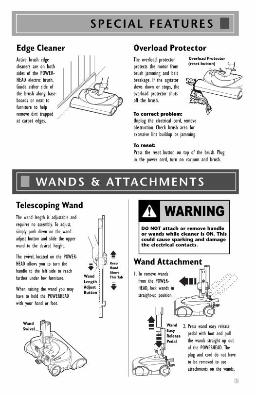
Telescoping WandThe wand length is adjustable andrequires no assembly. To adjust,simply push down on the wand adjust button and slide the upperwand to the desired height.
The swivel, located on the POWER-HEAD allows you to turn the handle to the left side to reach farther under low furniture.
When raising the wand you may have to hold the POWERHEAD with your hand or foot.
Wand Attachment1. To remove wands
from the POWER-HEAD, lock wands instraight-up position.
WANDS & ATTACHMENTS
SPECIAL FEATURES
Edge CleanerActive brush edgecleaners are on bothsides of the POWER-HEAD electric brush.Guide either side ofthe brush along base-boards or next tofurniture to helpremove dirt trappedat carpet edges.
Overload ProtectorThe overload protector protects the motor frombrush jamming and beltbreakage. If the agitatorslows down or stops, theoverload protector shuts off the brush.
To correct problem:Unplug the electrical cord, remove obstruction. Check brush area for excessive lint buildup or jamming.
To reset: Press the reset button on top of the brush. Plug in the power cord, turn on vacuum and brush.
OverloadProtectorReset Button
Overload Protector(reset button)
3
DO NOT attach or remove handleor wands while cleaner is ON. Thiscould cause sparking and damagethe electrical contacts.
2. Press wand easy releasepedal with foot and pull the wands straight up outof the POWERHEAD. Theplug and cord do not haveto be removed to useattachments on the wands.
WandSwivel
WandLengthAdjustButton
WandEasyReleasePedal
KeepHandAboveThis Tab
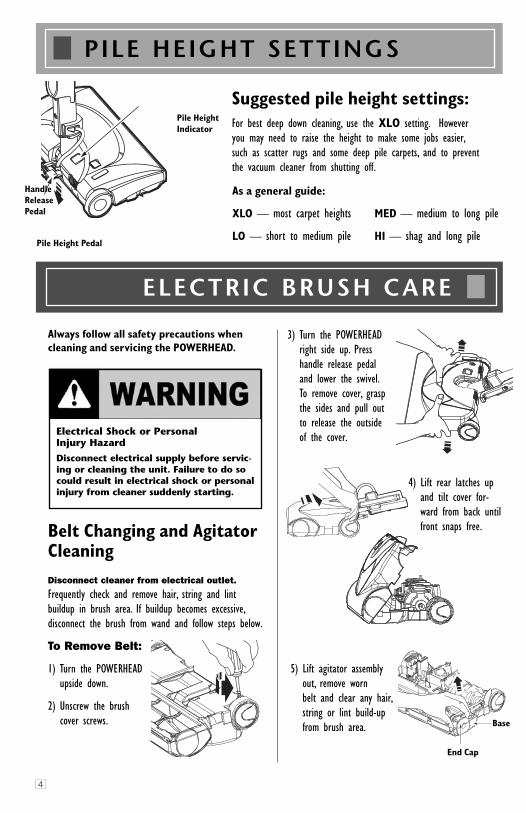
3) Turn the POWERHEADright side up. Presshandle release pedaland lower the swivel.To remove cover, graspthe sides and pull outto release the outsideof the cover.
4) Lift rear latches upand tilt cover for-ward from back untilfront snaps free.
5) Lift agitator assemblyout, remove worn belt and clear any hair,string or lint build-upfrom brush area.
Belt Changing and AgitatorCleaningDisconnect cleaner from electrical outlet.
Frequently check and remove hair, string and lint buildup in brush area. If buildup becomes excessive,disconnect the brush from wand and follow steps below.
To Remove Belt:
1) Turn the POWERHEAD upside down.
2) Unscrew the brush cover screws.
As a general guide:
XLO — most carpet heights
LO — short to medium pile
MED — medium to long pile
HI — shag and long pile
Suggested pile height settings: For best deep down cleaning, use the XLO setting. Howeveryou may need to raise the height to make some jobs easier,such as scatter rugs and some deep pile carpets, and to preventthe vacuum cleaner from shutting off.
4
PILE HEIGHT SETTINGS
Pile HeightIndicator
Pile Height Pedal
ELECTRIC BRUSH CARE
Electrical Shock or Personal Injury Hazard
Disconnect electrical supply before servic-ing or cleaning the unit. Failure to do socould result in electrical shock or personalinjury from cleaner suddenly starting.
Always follow all safety precautions whencleaning and servicing the POWERHEAD.
Base
End Cap
Base
HandleReleasePedal
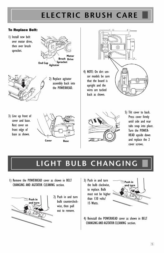
To Replace Belt:
1) Install new belt over motor drive,then over brushsprocket.
2) Replace agitator assembly back into the POWERHEAD.
3) Line up front ofcover and base.Rest cover onfront edge ofbase as shown.
4) NOTE: On dirt sen-sor models be surethat the board isupright and thewires are tuckedback as shown.
5) Tilt cover to back.Press cover firmlyuntil side and reartabs snap into place.Turn the POWER-HEAD upside downand replace the 2cover screws.
LIGHT BULB CHANGING
ELECTRIC BRUSH CARE
5
End CapAgitator
BrushSprocket
MotorDrive
Cover Base
1) Remove the POWERHEAD cover as shown in BELTCHANGING AND AGITATOR CLEANING section.
2) Push in and turnbulb counterclock-wise, then pullout to remove.
3) Push in and turnthe bulb clockwise,to replace. Bulbmust not be higherthan 130 volts/15 Watts.
4) Reinstall the POWERHEAD cover as shown in BELTCHANGING AND AGITATOR CLEANING section.
Push InAnd Turn
Push InAnd Turn
Push inand turn
Push inand turn
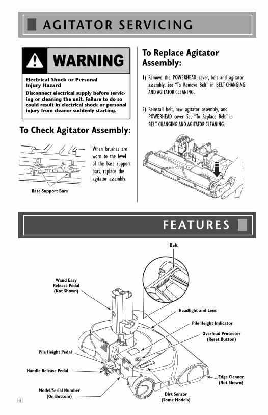
AGITATOR SERVICING
To Check Agitator Assembly:
When brushes areworn to the level of the base supportbars, replace the agitator assembly.
To Replace AgitatorAssembly: 1) Remove the POWERHEAD cover, belt and agitator
assembly. See “To Remove Belt” in BELT CHANGINGAND AGITATOR CLEANING.
2) Reinstall belt, new agitator assembly, and POWERHEAD cover. See “To Replace Belt” in BELT CHANGING AND AGITATOR CLEANING.
Electrical Shock or Personal Injury Hazard
Disconnect electrical supply before servic-ing or cleaning the unit. Failure to do socould result in electrical shock or personalinjury from cleaner suddenly starting.
Base Support Bars
Belt
Wand EasyRelease Pedal(Not Shown)
Pile Height Pedal
Handle Release Pedal
Model/Serial Number(On Bottom) Dirt Sensor
(Some Models)
Edge Cleaner(Not Shown)
Overload Protector(Reset Button)
Pile Height Indicator
Headlight and Lens
6
FEATURES
DIRT SENSOR
7
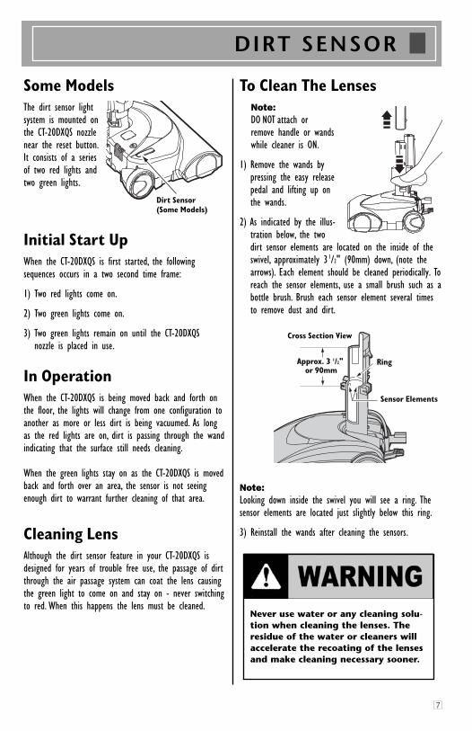
Some ModelsThe dirt sensor light system is mounted onthe CT-20DXQS nozzle near the reset button.It consists of a series of two red lights andtwo green lights.
Initial Start UpWhen the CT-20DXQS is first started, the followingsequences occurs in a two second time frame:
1) Two red lights come on.
2) Two green lights come on.
3) Two green lights remain on until the CT-20DXQS nozzle is placed in use.
In OperationWhen the CT-20DXQS is being moved back and forth onthe floor, the lights will change from one configuration toanother as more or less dirt is being vacuumed. As longas the red lights are on, dirt is passing through the wandindicating that the surface still needs cleaning.
When the green lights stay on as the CT-20DXQS is movedback and forth over an area, the sensor is not seeingenough dirt to warrant further cleaning of that area.
Cleaning LensAlthough the dirt sensor feature in your CT-20DXQS isdesigned for years of trouble free use, the passage of dirtthrough the air passage system can coat the lens causingthe green light to come on and stay on - never switchingto red. When this happens the lens must be cleaned.
To Clean The LensesNote:DO NOT attach or remove handle or wands while cleaner is ON.
1) Remove the wands by pressing the easy releasepedal and lifting up on the wands.
2) As indicated by the illus-tration below, the twodirt sensor elements are located on the inside of theswivel, approximately 31/2" (90mm) down, (note thearrows). Each element should be cleaned periodically. Toreach the sensor elements, use a small brush such as abottle brush. Brush each sensor element several timesto remove dust and dirt.
Note:Looking down inside the swivel you will see a ring. Thesensor elements are located just slightly below this ring.
3) Reinstall the wands after cleaning the sensors.
DirtSensor(Som e M odels)Dirt Sensor (Some Models)
Cross Section View
Ring
Sensor Elements
Approx. 3 1/2"or 90mm
Never use water or any cleaning solu-tion when cleaning the lenses. Theresidue of the water or cleaners willaccelerate the recoating of the lensesand make cleaning necessary sooner.
5242
10 14
40
49
43
35
31 19
22
24 48
55
38
37
541
27
30 30
34
4628
29 33
32
35
31 19
24
8 16
17 39
38
25
24
535150
5242
36
45
139
10 1443 22
44
37
5441
2612
5555
23 231118
471521
24
5
55
Cen-Tec CT-20DXQD Electric Brush Parts Explosion
32
Cen-Tec CT-20DXQD Electric Brush Parts Explosion
25
Cen-Tec CT-20DXQD Electric Brush Parts Explosion
21
19
31
Cen-Tec CT-20DXQD Electric Brush Parts Explosion
8
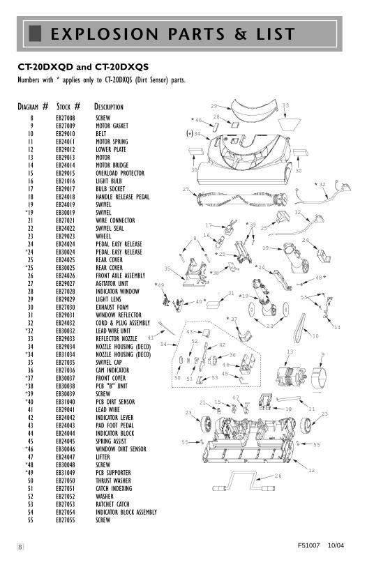
EXPLOSION PARTS & LIST
CT-20DXQD and CT-20DXQSNumbers with * applies only to CT-20DXQS (Dirt Sensor) parts.
DIAGRAM # STOCK # DESCRIPTION8 EB27008 SCREW9 EB27009 MOTOR GASKET
10 EB29010 BELT11 EB24011 MOTOR SPRING12 EB29012 LOWER PLATE13 EB29013 MOTOR14 EB24014 MOTOR BRIDGE15 EB29015 OVERLOAD PROTECTOR16 EB21016 LIGHT BULB17 EB29017 BULB SOCKET18 EB24018 HANDLE RELEASE PEDAL19 EB24019 SWIVEL
*19 EB30019 SWIVEL21 EB27021 WIRE CONNECTOR22 EB24022 SWIVEL SEAL23 EB29023 WHEEL24 EB24024 PEDAL EASY RELEASE
*24 EB30024 PEDAL EASY RELEASE 25 EB24025 REAR COVER
*25 EB30025 REAR COVER26 EB24026 FRONT AXLE ASSEMBLY27 EB29027 AGITATOR UNIT28 EB27028 INDICATOR WINDOW29 EB29029 LIGHT LENS30 EB27030 EXHAUST FOAM31 EB29031 WINDOW REFLECTOR32 EB24032 CORD & PLUG ASSEMBLY
*32 EB30032 LEAD WIRE UNIT33 EB29033 REFLECTOR NOZZLE34 EB29034 NOZZLE HOUSING (DECO)
*34 EB31034 NOZZLE HOUSING (DECO)35 EB27035 SWIVEL CAP36 EB27036 CAM INDICATOR
*37 EB30037 FRONT COVER*38 EB30038 PCB "B" UNIT*39 EB30039 SCREW*40 EB31040 PCB DIRT SENSOR41 EB29041 LEAD WIRE42 EB24042 INDICATOR LEVER43 EB24043 PAD FOOT PEDAL44 EB24044 INDICATOR BLOCK45 EB24045 SPRING ASSIST
*46 EB30046 WINDOW DIRT SENSOR47 EB24047 LIFTER
*48 EB30048 SCREW*49 EB31049 PCB SUPPORTER50 EB27050 THRUST WASHER 51 EB27051 CATCH INDEXING52 EB27052 WASHER53 EB27053 RATCHET CATCH54 EB27054 INDICATOR BLOCK ASSEMBLY55 EB27055 SCREW
*
*
*
*
*
*
*
*
*
(*)
**
F51007 10/04

H-P Products, Inc.512 W. Gorgas Street
Louisville, Ohio 44641-0912
®
CT20DX
LIMITED WARRANTYH-P PRODUCTS, INC. warrants that the CT20DX Powerhead,when used for household purposes, pursuant to Seller’s instructions, willbe free from defects in materials and workmanship for a period of one yearfrom the date of the initial consumer purchase. H-P PRODUCTS, INC.warrants that the CT20DX Powerhead, when used in a commercialapplication, pursuant to Seller’s instructions, will be free from defectsin materials and workmanship for a period of ninety (90) days from the dateof the initial sale by H-P PRODUCTS, INC. This warranty is limitedto the replacement of defective parts and any costs of shippingshall be incurred by the purchaser. THIS WARRANTY IS EXCLUSIVEAND IS IN LIEU OF ALL OTHER WARRANTIES, EXPRESS, IMPLIED,OR STATUTORY, AND H-P PRODUCTS, INC. SPECIFICALLY DIS-CLAIMS RESPONSIBILITY FOR CONSEQUENTIAL AND INCIDEN-TAL DAMAGES, AND LIMITS THE IMPLIED WARRANTY OF MER-CHANTABILITY TO THE PERIOD OF EFFECTIVENESS OF THISEXPRESS WARRANTY.
WARNING:ELECTRIC SHOCK
COULD OCCUR IF USEDON WET SURFACES

H-P Products, Inc.512 W. Gorgas Street
Louisville, Ohio 44641-0912
®