fa 3000k fully automatic sawbrobo.com.au/wp-content/uploads/2016/08/fa_3000k_users_manual-min2.pdf50...
TRANSCRIPT
Precision Drilling Machines Tapping Machines Multi Head Drills Tool Grinders
Tool Post Grinders Machine Vices Special Production Equipment
Accessories Riveting Machines Pedestal Grinders Metal Cutting Saws Linishers
YOUR BROBO WALDOWN DISTRIBUTOR IS:
PRODUCT AND MAINTENANCE MANUALFA 3000K FULLY AUTOMATIC SAW
MODEL: S350D FERROUS SAW
!
BROBO WALDOWN (AUST) PTY. LTD.
A.C.N. 098 264 316A.B.N. 42 098 264 316
65-67 Williams Rd, Dandenong, 3175PO BOX 4274 Dandenong Sth, 3164Victoria, AUSTRALIA.Tel: 61 3 9794 8751 Email: [email protected] Fax: 61 3 9794 8792 Website: www.brobo.com.au
Cer
tifi
ed S
yste
m
Quality ISO 9001

FA 3000K PRODUCT OPERATION AND MAINTENANCE MANUAL
Table of Contents
egaP noitceS
1 noitacificepS lacinhceT .1
3 enihcaM eht fo noitallatsnI .2 3 enihcaM eht gnildnaH dna gnikcapnU 1.2 4 stnemeriuqeR muminiM 2.2 5 noitarepO dna snoitcnuF niaM .3 6 puteS lareneG K0003 AF 1.3 9 puteS edalB 2.3 01 puteS noitautcA waS 3.3 21 edoM gnittuC citamotuA-imeS 4.3 21 erutaeF reppotS htgneL 1.4.3 41 edoM gnittuC citamotuA-ylluF 5.3
3.6 Saving and Retrieving a Cutting Job in Memory 17 02 sneercS pleH smralA 7.3
12 selbamusnoC dna ecnanetniaM tinU .4 12 rotarepO eht fo eloR 1.4
4.2 General Maintenance of Functioning Components 21 32 stnemeriuqeR ecnanetniaM 3.4
42 straP erapS dna ylbmessA ,stuoyaL .5
24 noitneverP tnediccA dna ytefaS .6 24 enihcaM eht fo noitarepO 1.6 34 setoN ytefaS 2.6 54 rotarepO eht rof ecivdA 3.6 74 sdradnatS ecnerefeR 4.6
84 ediuG gnitoohselbuorT .7 84 gnitoohselbuorT lareneG 1.7
94 tnemssessA drazaH / ksiR A xidneppA 5 B xidneppA 0Warranty

31 January 2009 Technical Specifications 1
1. TECHNICAL SPECIFICATIONS Cutting Unit Specifications Cutting Unit Brobo S350D Ferrous Unit Main Motor Power 2.2 KW (415 V, 3-phase) Main Motor Torque 7.5 Nm Main Motor RPM 2800 RPM (at 50 Hz) Main Drive Ratio 1:33 (Reduction) Blade RPM (Speed) 30 to 80 RPM (33 to 88 m/min) Sound Level < 85 dB(A) Blade Specification Standard Blade HSS AISI M-Z High Speed Steel (62-64 HRC, Hollow Ground) Size ∅350 mm, 180 teeth, 2.5 mm thickness Mount ∅40 mm bore, 2 × ∅8 mm holes, ∅55 mm PCD (Brobo mount)
Blade Selection Chart (HSS Ø350 mm Blade Only)
Material
Outer Diamater (mm)
Wall Thickness
(mm)
Recommended Number of Teeth
1 350 2 280 20 3 220 1 260 2 250 3 180 40
4 160 1 350 2 280 3 200 4 180
50
5 160 1 320 2 220 3 200 4 180
80
5 160 1 300 2 200 3 180 4 140
100
5 120 1 300 2 200 3 180 4 160
HOLLOW SECTIONS
120
5 120 10 280 20 200 30 160 40 140 50 100
SOLID SECTIONS
60
-
80
Table 1.1 – Blade Selection Chart (Ø350 mm HSS Blade)
NOTE – This chart is issued as a GUIDE ONLY and appropriate blade selection is wholly the responsibility of the Operator. Brobo Waldown Pty Ltd does not accept any responsibility for unsatisfactory cutting performance and/or machine or blade breakage as a result of blade selection.

31 January 2009 Technical Specifications 2
Vice Clamps Type Manual adjusting pneumatic clamp Air Requirements Dry, filtered, lubricated air supply Working Air Pressure 600 KPa (6 bar, 87 PSI) Maximum Air Pressure 1000 KPa (10 bar, 145 PSI) Clamping Range 0 to 135 mm (145 mm without wear plates) Clamping Force 1620 N/bar (9720 N at 6 bar working pressure) Cutting Range
Profile Angle Max Cutting Capacity (mm)
45° 115 RHS Bar 90° 110
45° 100 × 100 RHS Square 90° 85 × 85
45° 85 × 135 RHS Rectangular 90° 75 × 95
Solid Sections 90° 60
Table 1.2 – Saw Cutting Range
NOTE: Values based on a full sized new blade. Capacity is reduced with a worn or resharpened blade. Saw Feed Specifications Feed Rate (max) 32 mm/s Feed Stroke (max) 125 mm Material Feed Specifications Feed Rate (max) 500 mm/s Feed Stroke (max) 2850 mm Overall Dimensions Dimensions 3,880 × 1,800 × 560 mm Weight 315 kg Table Working Height 968mm

31 January 2009 Installation of the Machine 3
2. INSTALLATION OF THE MACHINE 2.1 Unpacking and Handling the Machine
FA 3000K is a versatile automatic cold saw which can significantly increase your cutting productivity for small and large jobs. It consists of the following major components (Figure 2.1):
� Brobo S350D cold saw with automatic actuation � F3000 automatic material feeder � Electrical control box with 6 inch HMI touch screen
Figure 2.1 – FA 3000K Major Components
FA 3000K will arrive at your workshop in two packages:
� FA Cold saw unit with electrical box � Material Feeder Unit
Cold saw unit is the heaviest of the components, hence needs to be placed in position first with the rest of the machine to be built around it. When selecting suitable space keep in mind the space requirements of the feeder unit which is 3+ m long. When happy with unit position, unpack the material feeder and proceed first to attach the feeder legs to the main body (using four M8 bolts), and then to attach the material feeder itself to the cold saw unit (two M10 bolts). Refer to Section 5 for machine assembly drawings. Place the electrical box as illustrated in Figure 2.1, leaving the Operator in optimum position, accessible to controls and the main cutting area, but out of the way of the machine cutting and feeding zone. When determining location for the machine, ensure that floor is as level as possible and that the requirements from Section 2 (below) and safety precautions in Section 6 are adequately met. Additionally for best performance ensure that the feeder working table is leveled, adjusting the two standing feet if necessary. When sourcing the power supply cable, check that they are within the acceptable standards (Section 6). Install the power cable as per electrical schematics in Figures 5.5 and 5.6 (Section 5). The installation of the Earthing system must comply with the IEC Standards Part 195: Earthing and Protection Against Electric Shocks 1998.
Material Feeder
Unit Electrical
Box
FA Cold Saw
Unit

31 January 2009 Installation of the Machine 4
Insufficient lighting during the unit operation would constitute a safety hazard according to the ISO 8995 – 2002 ‘Lighting of Indoor Workplaces’. For this reason, the user must provide adequate lighting in the working area (500 LUX), while also preventing dazzling illumination sources.
2.2 Minimum Requirements For the machine to operate correctly, the place where the saw is to be positioned must be in the vicinity of and satisfy the following conditions:
1) 415 V (3 phase) with neutral wire and ground
2) Lighting more than 500 LUX Note that neutral wire MUST be connected to the system. Without neutral wire, sensitive electronic equipment can be damaged.
31 January 2009 Main Functions and Operation 5
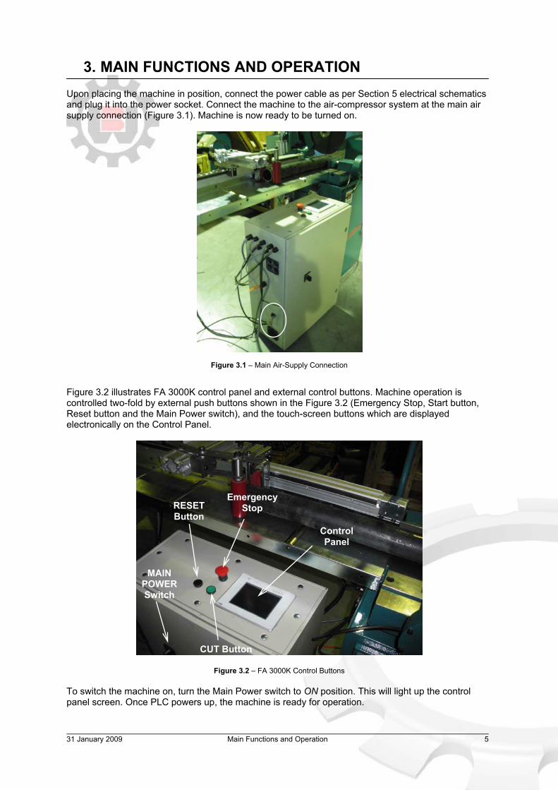
3. MAIN FUNCTIONS AND OPERATION Upon placing the machine in position, connect the power cable as per Section 5 electrical schematics and plug it into the power socket. Connect the machine to the air-compressor system at the main air supply connection (Figure 3.1). Machine is now ready to be turned on.
Figure 3.1 – Main Air-Supply Connection
Figure 3.2 illustrates FA 3000K control panel and external control buttons. Machine operation is controlled two-fold by external push buttons shown in the Figure 3.2 (Emergency Stop, Start button, Reset button and the Main Power switch), and the touch-screen buttons which are displayed electronically on the Control Panel.
Figure 3.2 – FA 3000K Control Buttons To switch the machine on, turn the Main Power switch to ON position. This will light up the control panel screen. Once PLC powers up, the machine is ready for operation.
Emergency Stop
CUT Button
RESET Button
MAIN POWER Switch
Control Panel

31 January 2009 Main Functions and Operation 6
3.1 FA 3000K General Setup Upon powering up, the first screen displayed is the error screen showing current error messages as shown in Figure 3.3:
� Emergency Stop depressed � Feeder position not homed (material feeder) � Feeder axis not homed (saw actuator)
Figure 3.3 – Error Screen
To clear the Emergency Stop message, ensure red mushroom button is not depressed, and press the black Reset button (Figure 3.2). After every startup or reset, machine requires both its feed axes (material feeder and saw actuator) homed to a known sensor position. To home the axes, press Home button which will take you to Home screen, then press Reference button. Both machine axes will seek out sensor positions, which are shown in Figure 3.4.
Figure 3.4 – Material Feeder (Right) and Saw Actuator (Left) Home Sensors
Once both axes are homed, machine is ready for cutting.
WARNING – Before homing the actuator and feeder ALWAYS CHECK that there are no loose objects left in their path. Loose objects can cause actuator and feeder to jam, risking damage to the machine and danger to the Operator
HOME BUTTON – Back to Home Screen
31 January 2009 Main Functions and Operation 7
FA 3000K is a versatile automated saw with modes to cover jobs from cutting a bar to length to a 1,000 piece cutting job. All machine cutting is covered across three modes of operation:
� Manual mode � Semi-automatic mode
o With / Without Length Stopper � Fully-automatic mode
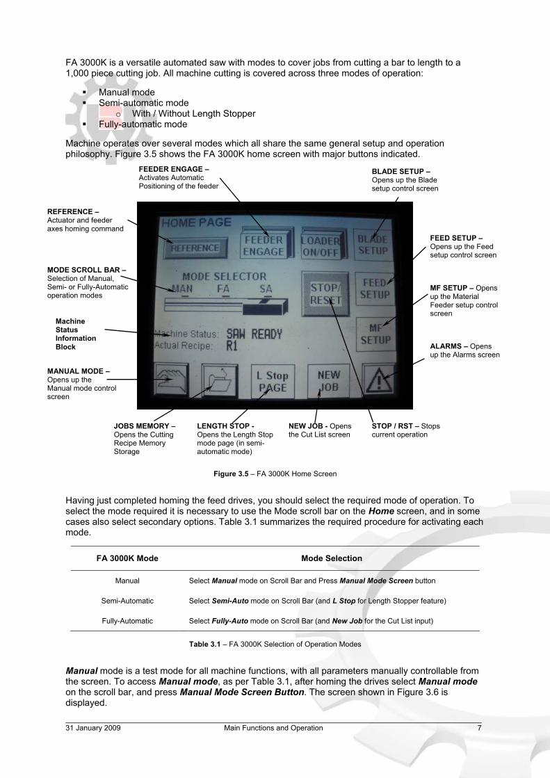
Machine operates over several modes which all share the same general setup and operation philosophy. Figure 3.5 shows the FA 3000K home screen with major buttons indicated.
Figure 3.5 – FA 3000K Home Screen Having just completed homing the feed drives, you should select the required mode of operation. To select the mode required it is necessary to use the Mode scroll bar on the Home screen, and in some cases also select secondary options. Table 3.1 summarizes the required procedure for activating each mode.
FA 3000K Mode Mode Selection
Manual Select Manual mode on Scroll Bar and Press Manual Mode Screen button
Semi-Automatic Select Semi-Auto mode on Scroll Bar (and L Stop for Length Stopper feature)
Fully-Automatic Select Fully-Auto mode on Scroll Bar (and New Job for the Cut List input)
Table 3.1 – FA 3000K Selection of Operation Modes
Manual mode is a test mode for all machine functions, with all parameters manually controllable from the screen. To access Manual mode, as per Table 3.1, after homing the drives select Manual mode on the scroll bar, and press Manual Mode Screen Button. The screen shown in Figure 3.6 is displayed.
REFERENCE – Actuator and feeder axes homing command
MODE SCROLL BAR – Selection of Manual, Semi- or Fully-Automatic operation modes
FEEDER ENGAGE – Activates Automatic Positioning of the feeder
BLADE SETUP –Opens up the Blade setup control screen
FEED SETUP –Opens up the Feed setup control screen
MF SETUP – Opens up the Material Feeder setup control screen
MANUAL MODE – Opens up the Manual mode control screen
Machine Status Information Block
JOBS MEMORY – Opens the Cutting Recipe Memory Storage
LENGTH STOP - Opens the Length Stop mode page (in semi-automatic mode)
NEW JOB - Opens the Cut List screen
ALARMS – Opens up the Alarms screen
STOP / RST – Stops current operation
31 January 2009 Main Functions and Operation 8
`
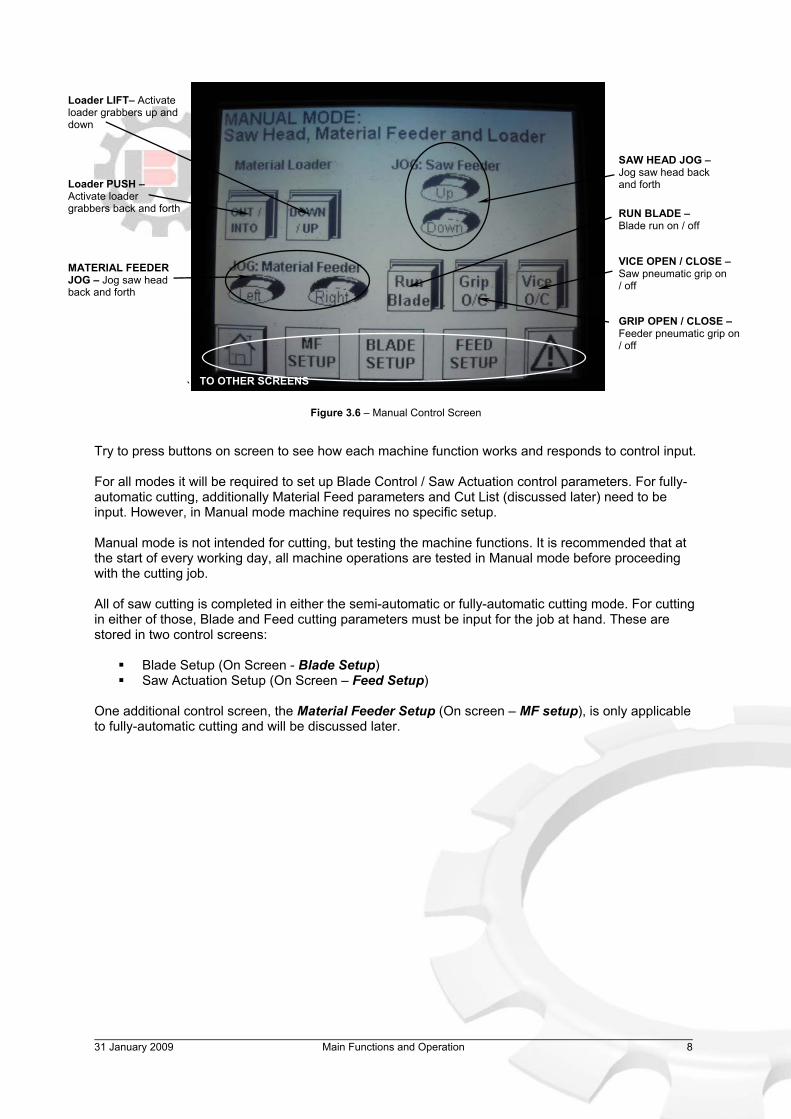
Figure 3.6 – Manual Control Screen
Try to press buttons on screen to see how each machine function works and responds to control input. For all modes it will be required to set up Blade Control / Saw Actuation control parameters. For fully-automatic cutting, additionally Material Feed parameters and Cut List (discussed later) need to be input. However, in Manual mode machine requires no specific setup. Manual mode is not intended for cutting, but testing the machine functions. It is recommended that at the start of every working day, all machine operations are tested in Manual mode before proceeding with the cutting job. All of saw cutting is completed in either the semi-automatic or fully-automatic cutting mode. For cutting in either of those, Blade and Feed cutting parameters must be input for the job at hand. These are stored in two control screens:
� Blade Setup (On Screen - Blade Setup) � Saw Actuation Setup (On Screen – Feed Setup)
One additional control screen, the Material Feeder Setup (On screen – MF setup), is only applicable to fully-automatic cutting and will be discussed later.
SAW HEAD JOG – Jog saw head back and forth
MATERIAL FEEDER JOG – Jog saw head back and forth
Loader LIFT– Activate loader grabbers up and down
Loader PUSH – Activate loader grabbers back and forth
GRIP OPEN / CLOSE – Feeder pneumatic grip on / off
VICE OPEN / CLOSE – Saw pneumatic grip on / off
RUN BLADE – Blade run on / off
TO OTHER SCREENS

31 January 2009 Main Functions and Operation 9
3.2 Blade Setup Go back to Home screen (Figure 3.5) and press Blade Setup Button. Figure 3.7 illustrates the Blade setup control screen. Blade setup covers all blade rotation (main motor) parameters most important of which are Blade RPM and Overload (Ramp) Control. This parameters screen is required to be setup for all cutting on the machine.
Figure 3.7 – Blade Setup Screen
FA 3000K was designed for cutting small and medium steel profiles, for which low cutting speed (RPM) is most suitable for achieving optimum blade life. Blade speed control on the machine has a factory set limit of between 30 to 90 RPM, which will cover all steel cutting needs. To set the blade RPM, press on the touch screen Speed (RPM) value displayed and input the required RPM values. FA 3000K comes with an in-built system which monitors the load on the main motor and, in case of an overload, momentarily reverses the feed until main motor load falls. In practice, there is no “reversal” visible, and when the system intervenes it has the appearance of slowing down and speeding up the feed until it safely completes the cut. To set ramp feedback point or blade RPM, press on the value on display and enter the desired percentage. Recommended ramp control overload value varies according to the type of cutting, but between 60 to 70 per cent is appropriate for most general cutting. For heavy duty steel cutting it may be necessary to increase feed to above 70 per cent. However, in such cases the Operator needs to take special consideration setting up ALL cutting parameters (feed rate, blade RPM, overload). Ramp Control value should NEVER be set below 50 per cent. This, in addition to unnecessarily slowing down the cutting, risks abnormal operation.
Speed (RPM) – Blade RPM Setting (30 to 90 RPM)
Actual Speed (RPM) – Real-time blade RPM measurement
Feed Ramp Control On / Off – Main motor overload monitoring
Overload trigger (%) – Ramp control activation point
Actual Load (%) – Real-time main motor load measure
Blade C Run – Command to leave blade turning continuously between cuts
Vice Open / Close – Cutting vice manual On / Off
Run Blade – Manual blade run On / Off
TO OTHER SCREENS

31 January 2009 Main Functions and Operation 10
3.3 Saw Actuation Setup Return to Home screen (Figure 3.5) and press Feed Setup Button. Feed screen (Figure 3.8) controls the feed rate of the saw during a cut, with a cut cycle divided into five control segments, each with feed and position defined. This control screen is required to be setup for all cutting on the machine.
Figure 3.8 – Saw Actuation Setup Screen
FA 3000K saw is fed by an electric actuator with up to 250 mm of stroke. On FA 3000K the usable stroke, in terms of blade movement, is set at 125 mm. Actuator homes to 0 position and all references to FA 3000K saw head position are to the blade movement relative to this home position. In practice, the 0 position is defined as the head position where the bottom blade edge is 125 mm above the cutting table (Figure 3.9).
Figure 3.9 – Definition of Saw Head Home Position (0)
125 mm
Cutting Feed Speed (mm/s)
Approach and Slow Entry Speed (%) – Set as percentage of the Cutting Speed
Slow Exit and Retract Speed (%) – Set as percentage of the Cutting Speed
Saw Actuator Jog – Up and Down and speed control (mm/s)
Position, Load, Speed (mm, %, mm/s) – Real-time position speed and
Loading, Entry Cut, Middle Cutting, Exit Cutting, Retract Points (mm)
Set Actual As – Inputs current feed position as a point
Overload monitoring System (On/Off)
31 January 2009 Main Functions and Operation 11
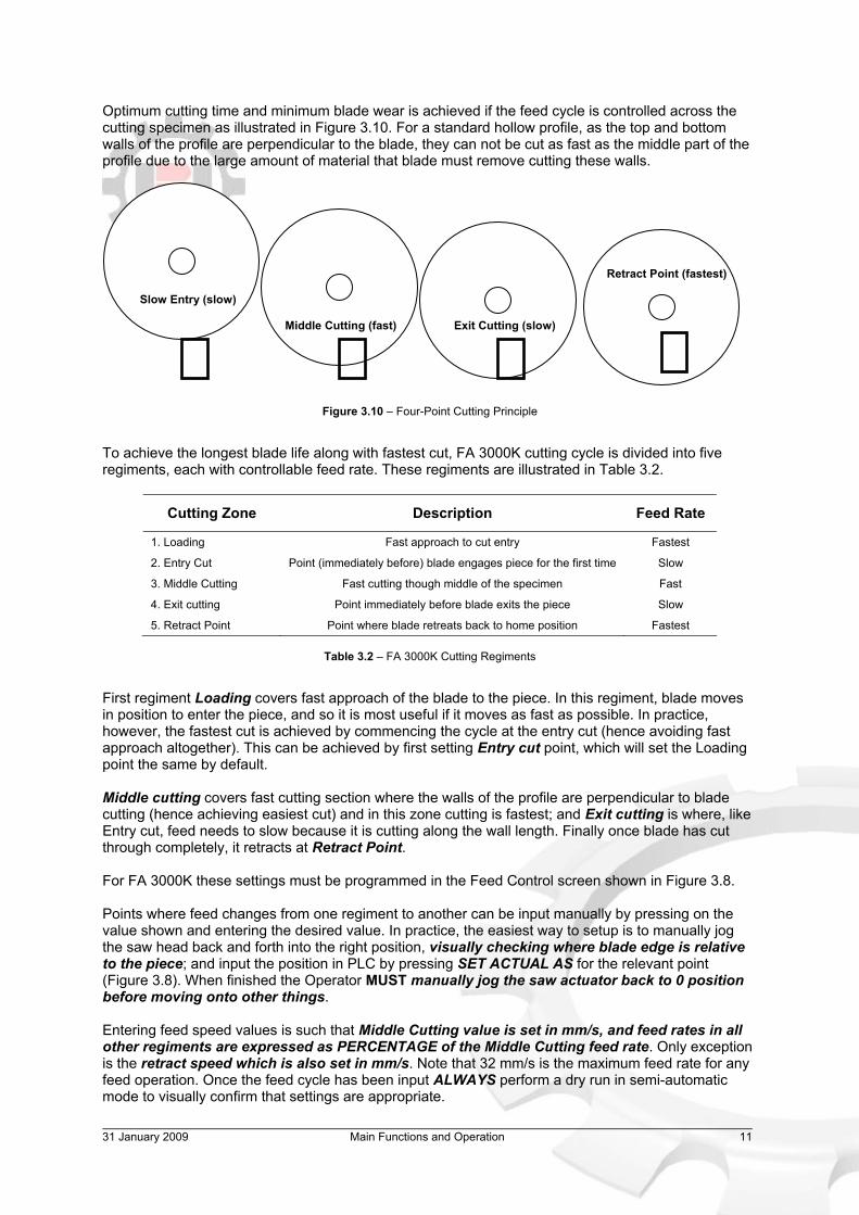
Optimum cutting time and minimum blade wear is achieved if the feed cycle is controlled across the cutting specimen as illustrated in Figure 3.10. For a standard hollow profile, as the top and bottom walls of the profile are perpendicular to the blade, they can not be cut as fast as the middle part of the profile due to the large amount of material that blade must remove cutting these walls.
Figure 3.10 – Four-Point Cutting Principle
To achieve the longest blade life along with fastest cut, FA 3000K cutting cycle is divided into five regiments, each with controllable feed rate. These regiments are illustrated in Table 3.2.
Cutting Zone Description Feed Rate
1. Loading Fast approach to cut entry Fastest
2. Entry Cut Point (immediately before) blade engages piece for the first time Slow
3. Middle Cutting Fast cutting though middle of the specimen Fast
4. Exit cutting Point immediately before blade exits the piece Slow
5. Retract Point Point where blade retreats back to home position Fastest
Table 3.2 – FA 3000K Cutting Regiments
First regiment Loading covers fast approach of the blade to the piece. In this regiment, blade moves in position to enter the piece, and so it is most useful if it moves as fast as possible. In practice, however, the fastest cut is achieved by commencing the cycle at the entry cut (hence avoiding fast approach altogether). This can be achieved by first setting Entry cut point, which will set the Loading point the same by default. Middle cutting covers fast cutting section where the walls of the profile are perpendicular to blade cutting (hence achieving easiest cut) and in this zone cutting is fastest; and Exit cutting is where, like Entry cut, feed needs to slow because it is cutting along the wall length. Finally once blade has cut through completely, it retracts at Retract Point. For FA 3000K these settings must be programmed in the Feed Control screen shown in Figure 3.8. Points where feed changes from one regiment to another can be input manually by pressing on the value shown and entering the desired value. In practice, the easiest way to setup is to manually jog the saw head back and forth into the right position, visually checking where blade edge is relative to the piece; and input the position in PLC by pressing SET ACTUAL AS for the relevant point (Figure 3.8). When finished the Operator MUST manually jog the saw actuator back to 0 position before moving onto other things. Entering feed speed values is such that Middle Cutting value is set in mm/s, and feed rates in all other regiments are expressed as PERCENTAGE of the Middle Cutting feed rate. Only exception is the retract speed which is also set in mm/s. Note that 32 mm/s is the maximum feed rate for any feed operation. Once the feed cycle has been input ALWAYS perform a dry run in semi-automatic mode to visually confirm that settings are appropriate.
Retract Point (fastest)
Exit Cutting (slow) Middle Cutting (fast)
Slow Entry (slow)

31 January 2009 Main Functions and Operation 12
3.4 Semi-Automatic Cutting Mode Cutting in semi-automatic mode requires the following:
� Set up the Blade Setup parameters for piece to be cut as described in Section 3.2 � Set up the Feed Setup parameters (Saw Actuation) for the piece, as described in Section 3.3 � Set up the piece in the cutting zone at the point where it needs to be cut � Adjust the cutting vice manually to 5 to 10 mm off the piece (so that when it is activated piece
is gripped adequately)
Following instructions up to now, the material and saw actuation axes were homed in Section 3.1, appropriate Blade RPM parameters setup in Section 3.2, and feed rate points input in Section 3.3. Switch the machine to Semi-Automatic mode on the Home screen mode scroll bar (Figure 3.5). With all the cut parameters setup, all that is left is to set the piece up for required length cut and adjust the cutting vice. Make sure the cutting vice is within 5 to 10 mm of the piece (with no air pressure) for adequate grip. If necessary test the grip using the manual Vice On/Off button in the Blade Setup screen (Figure 3.7). When everything is ready, press the green CUT button to activate the cutting cycle. Vice will automatically clamp the piece, and saw move through the pre-programmed cycle, cutting the piece and returning to starting position once complete. During the cut Operator can switch screens with real-time cutting information available in Blade and Feed Setup screens. Information like saw head position, speed and the load on the main motor and actuator are displayed. You can adjust any cutting parameters previously set in Blade and Feed Setup, while the machine is running and the changes will take effect within the same cycle. As soon as the piece is cut blade will stop and retract. For cutting large pieces option Blade C Run in Blade Setup parameters (Figure 3.7) will leave the blade running while it’s retracting, allowing for easier removal of the blade from the piece.
3.4.1 Length Stopper Feature A special feature of the semi-automatic mode is the Length Stopper mode which allows setup of the feeder to function as a manual stop. Length stopper mode requires the following:
� Set up the Blade Setup parameters for piece to be cut as described in Section 3.2 � Set up the Feed Setup parameters (Saw Actuation) for the piece, as described in Section 3.3 � Adjust the cutting vice manually to 5 to 10 mm off the piece (so that when it is activated piece
is gripped adequately) � Clamp a piece to be used as the stop in the feeder clamp using a manual clamp command on
the L Stop page � Calibrate the stop piece to the position of the blade � Input the required length of cut and press the GO button for the stop to take position
Cutting in length stopper mode is identical to cutting in semi-automatic mode with additional step of setting up the stopper. Following instructions up to now, it is assumed that material and saw actuation axes were homed (Section 3.1), appropriate Blade RPM parameters setup (Section 3.2), and feed rate points input (Section 3.3). Go to machine Home screen and switch the machine to the Semi-Automatic mode on the scroll bar, and press L Stop. Length Stop control screen appears shown in Figure 3.11.
31 January 2009 Main Functions and Operation 13
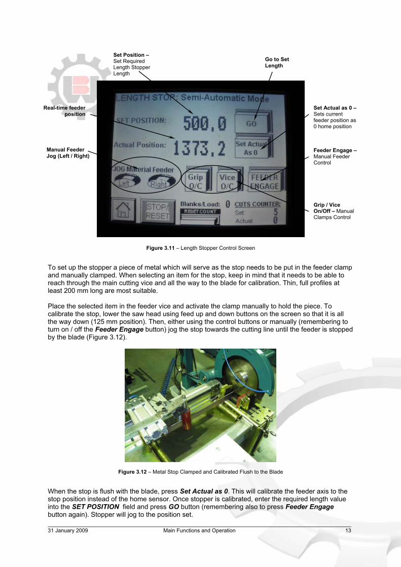
Figure 3.11 – Length Stopper Control Screen
To set up the stopper a piece of metal which will serve as the stop needs to be put in the feeder clamp and manually clamped. When selecting an item for the stop, keep in mind that it needs to be able to reach through the main cutting vice and all the way to the blade for calibration. Thin, full profiles at least 200 mm long are most suitable. Place the selected item in the feeder vice and activate the clamp manually to hold the piece. To calibrate the stop, lower the saw head using feed up and down buttons on the screen so that it is all the way down (125 mm position). Then, either using the control buttons or manually (remembering to turn on / off the Feeder Engage button) jog the stop towards the cutting line until the feeder is stopped by the blade (Figure 3.12).
Figure 3.12 – Metal Stop Clamped and Calibrated Flush to the Blade
When the stop is flush with the blade, press Set Actual as 0. This will calibrate the feeder axis to the stop position instead of the home sensor. Once stopper is calibrated, enter the required length value into the SET POSITION field and press GO button (remembering also to press Feeder Engage button again). Stopper will jog to the position set.
Real-time feeder position
Set Actual as 0 – Sets current feeder position as 0 home position
Set Position – Set Required Length Stopper Length
Go to Set Length
Feeder Engage – Manual Feeder Control
Grip / Vice On/Off – Manual Clamps Control
Manual Feeder Jog (Left / Right)

31 January 2009 Main Functions and Operation 14
The machine can now cut as per normal semi-automatic mode operation with the length stopper set in place. Before cutting ALWAYS remember to jog the saw head back into 0 position as the machine won’t commence a cycle when the saw head is down. When cutting using the length stopper, the feeder is actively positioning itself and hence any impact hits with the piece result in slight movement of the stopper, which it actively corrects. Therefore, before commencing the cut, for best accuracy make sure the stopper has corrected its position for any slight displacements (by observing the values on the screen) before proceeding with the cut. When cutting in Length Stopper mode the material feeder is calibrated to the position of the metal piece it is holding and not its Home sensor. Once Length Stopper cutting is finished, the machine material feeder MUST be homed back to the home sensor by pressing Reference button in the Home screen. 3.5 Fully-Automatic Cutting Mode Cutting in fully-automatic mode requires the following:
� Set up the Blade Setup parameters for piece to be cut as described in Section 3.2 � Set up the Feed Setup parameters (Saw Actuation) for the piece, as described in Section 3.3 � Set up the Material Feeder parameters in MF Setup for the bar to be cut (described in Section
following) � Set up the piece on the working table through the cutting and feeder clamps � Adjust both feeder and the cutting manually to 5 to 10 mm off the piece (so that the piece is
gripped adequately at both ends) � Input the cut lengths and quantities required to be cut in the New Job screen
Cutting in fully-automatic mode requires the same Blade and Feed setup as semi-automatic, with additional setup of the feeder parameters and input of the required cutting lengths and quantities. Following instructions up to now, it is assumed that material and saw actuation axes were homed (Section 3.1), appropriate Blade RPM parameters setup (Section 3.2), and feed rate points input (Section 3.3). Switch the machine to Fully-Automatic mode on the Home screen (Figure 3.5) mode scroll bar and then press MF Setup button. This will open up the material feeder setup screen show in Figure 3.13.
Figure 3.13 – Material Feeder Setup Screen
Start Position Set
Off-cut Position Set
Feeder Engage – Manual Feeder Control On / OFF
Drop Position Set
Manual JOG – Manual Left / Right Jog
Feed Speed Controls

31 January 2009 Main Functions and Operation 15
For Fully-Automatic cutting, in MF Setup screen it is required to input:
� Feeder Start Position – position from which feeder commences the cycle � Feeder Off-Cut Position – position which is the closest feeder can approach the cutting line � Feeder Drop Position – position where feeder drops the off-cut into the off-cut chute
Starting Position is where feeder commences fully-automatic cycle, hence for maximum productivity, it is best to place it just right of the home sensor so that feeder has maximum flat length before it has to retract. Off-cut Position is after which the feeder will retract to grab more of the flat to feed or drop off the off-cut. This point should be set as close as possible to the vice to minimize material and time wastage. Drop Position, the last position required for material feeder setup, is the position from which the feeder will release what remains of the fully cut flat into the off-cut chute. Most convenient way to set the required feeder positions is to move the carriage by hand and press the appropriate Set Position button (Figure 3.13), which will input the current position of the feeder in PLC. To be able to move the feeder by hand feeder must be disengaged from PLC, by deactivating Feeder Engage button (if it is depressed). Feeder can also be jogged in position by Left and Right jog buttons on the screen. Once feeder parameters have been set up, place the bar(s) in position on the working table as shown in Figure 3.14.
Figure 3.14 – Bar Setup for Fully-Automatic Cutting
Bars must go through the feeder clamps and cutting vice with both clamps set up 5 to 10 off the piece to achieve good pneumatic grip. The machine commences cutting cycle by performing an initial cut for the off-cut. Hence, the manual placement of the bars by the Operator in the cutting vice (Figure 3.14) determines the length of the initial off-cut length.
WARNING – Some small-sized profiles require special consideration cutting in fully-automatic mode due to the risk of small pieces jamming in the block openings, risking damage to the machine and danger for the Operator. It is recommended that profiles likely to be able to fall through the block be cut in lengths no shorter than 100 mm.
Piece Setup for Fully-Automatic Cutting

31 January 2009 Main Functions and Operation 16
When bars are set up on the working table, ready to be cut, go back to Home screen and press New Job button. Control screen shown in Figure 3.15 appears.
Figure 3.15 – NEW JOB Screen, Required Inputs
To cut bars automatically it is required to input bar length, number of bundle-cut bars, and the length and number of pieces for each length per bar length. FA 3000K cut list is set up for three cutting lengths per bar termed A, B and C. Cut list MUST be input in this order. I.e. if you only need two bar lengths cut, you must use A and B slots (not A and C, for example). If all the parameters are input, machine will calculate the bar remaining after the cut (End rest). If the cut-list can’t be fit on one bar length, an error screen will display “Bar Too Short”. If the cut list is ok, End rest will be a positive value. Once this is achieved the machine is ready to cut. Before pressing the green CUT button, make sure that the Feeder Engage button is depressed (back in Home screen, Figure 3.5). This button allows PLC feeder control to be switched on / off, without which the feeder won’t move and cutting can’t commence. Press the green CUT button.
WARNING – Operator and personnel MUST NEVER stand in the end feed zone area while the feeder is operating due to high risk of unforeseen injury by a feeding profile (Figure 3.16).
Figure 3.16 – Exit Feed Danger Zone
No personnel allowed in the end-feed zone when the machine is operating.
Input - Bar Length
Input – Number of bars to be bundle-cut simultaneously
Input – Blade Thickness
Input – Cut lengths and pieces per one bar

31 January 2009 Main Functions and Operation 17
Machine will first clamp the piece(s) and perform the initial cut removing the end off-cut. Once the initial cut is complete, clamp will open and feeder will move the bar(s) distance of the length A, clamp the bars again and cut. The machine will complete all the cuts in the order:
� All A cuts first � All B cuts second � All C cuts last
Once it has performed the required number of cuts and completed the set job as per the cut list, the saw will stop and feeder will go back to Start Position. In terms of the PLC, the machine stops cutting when the actual counter is equal to pieces cut per one bar. Hence, if bundle cutting, machine will stop when actual counter is equal to pieces per one bar multiplied by Blanks/Load value. When preparing to do a job in a fully-automatic mode, it helps to remember that cutting is set up per bar length. Hence, the Operator needs to work out the best combination of cuts per bar length and the resulting number of bars needed for the job. 3.6 Saving and Retrieving a Cutting Job in Memory FA 3000K has memory capacity to store 50+ cut jobs which are available for quick job setup. Machine memory operation is designed so that the current setup of the machine can be directly saved into memory with no repeating of data input. Following previous instructions, a cutting job (semi or fully-automatic) has been completed successfully, leaving in the machine PLC all cutting setup parameters, including:
� Blade setup parameters � Feed setup parameters � Material Feeder setup parameters � Cut list data
Go to machine Home screen, and press the Jobs Memory button (Figure 3.5). Jobs Memory screen opens up (Figure 3.17).
Figure 3.17 – Memory Recipe Selection Screen
Scroll up and down to find an unused memory slot. Unused memory slots are named with a generic NAME17 title. When an unused slot is found, press Enter, which will load any existing slot data for viewing.
Go to first parameters screen
Load Job data for viewing

31 January 2009 Main Functions and Operation 18
Press on the slot generic name and enter a name this job will be known as. After the name has been entered, press Right button, which will take you to the first of the data screens (Figure 3.18).
Figure 3.18 – Cutting Parameters Storage, First Screen
All job parameters are stored in three data screens, which display the job parameters in PANEL (which acts as memory storage) and PLC (which holds the current machine settings). Press Right to move onto the second data screen (Figure 3.19), then press Right again to move onto the third data screen (Figure 3.20) noting the types and the values of the parameters shown in the storage, including current data for:
� Material Feeder setup (Screen 1) � Cut List (Screen 2) � Saw Feed setup (Screen 3)
Figure 3.19 – Cutting Parameters Storage, Second Screen
Cutting Parameters in PLC
Cutting Parameters in Memory (Panel)
SAVE RIGHT - Copy Parameters to PLC (Load Job from Memory)
SAVE LEFT - Copy Parameters to Panel (Save Job to Memory)
To Next Screen
SAVE RIGHT - Copy Parameters to PLC (Load Job from Memory)
SAVE LEFT - Copy Parameters to Panel (Save Job to Memory)
Cutting Parameters in Memory (Panel)
Cutting Parameters in PLC
To Third Screen

31 January 2009 Main Functions and Operation 19
Figure 3.20 – Cutting Parameters Storage, Third Screen To save a cutting job, Operator must copy data from PLC to PANEL. To retrieve a cutting job, Operator must copy data from PANEL to PLC. Hence to save a cutting job, in any of the three screens, press SAVE LEFT (Figures 3.18, 3.19, 3.20) which will copy all the parameters, in all three screens, from PLC to Panel memory. Scroll through the three screens to visually confirm all parameters have been copied. When copying data from PLC to Screen, make sure that the name of the job has also been copied into the memory. If it wasn’t press SAVE LEFT again or enter the name manually. Note that pressing the save button in ANY of the three data screens will save data across ALL of the screens. Retrieving data from memory is exactly the same procedure reversed, where instead of copying data from PLC to PANEL, parameters are copied from PANEL to PLC. This is illustrated in Figures 3.18 to 3.20. To retrieve the data, follow the same procedure described earlier, except use the SAVE RIGHT button to copy from Panel to PLC. The easiest way to remember the correct way to copy is to visually note on the screen from which to what side data is being copied and use save buttons accordingly.
SAVE RIGHT - Copy Parameters to PLC (Load Job from Memory) SAVE LEFT - Copy
Parameters to Panel (Save Job to Memory)
Cutting Parameters in Memory (Panel)
Cutting Parameters in PLC

31 January 2009 Main Functions and Operation 20
3.7 Alarms Help Screens
Alarm Notes
Actual Count Equal to Preset Value
PLC count of the pieces cut is equal to pieces set to be cut. Go to New Job and either press reset count or change the set number of pieces to be cut.
Drive Not Healthy Drive not ready for operation. Press Reset Alarm, or reset machine at ON/OFF switch. If persisting, check error code at the inverter and contact Brobo Waldown.
Drive Fault Operation problem with the drive. Check if there is a mechanical problem causing and overload or a jam. Press Reset alarm to continue.
Feed Position Not Homed
Saw head feed actuator not homed. Go to Home screen and press Reference button. Check there are no items in the way before homing.
Low Air Pressure Check if air hose is connected. Press Reset Alarm to continue. If problem occurs regularly, increase base pressure in the air compressor system.
Emergency Stop Emergency stop depressed. Twist release the red mushroom button and press BLACK reset button to clear the alarm.
Feed Position Not Homed
Material feeder not homed. Go to Home screen and press Reference button. Check there are no items in the way before homing.
Saw Blade Motor Overload
Main motor experienced protracted overload. Check if Overload Control setting is too low. Press Reset Alarm to continue. If problem persists check if anything is physically causing excessive load on main motor.
Bar Too Short for Set Lengths
The cut list entered in the New Job screen can not fit on a bar length. Rearrange the cut list to fit the bar or use bar of longer length.
Loading Sequence Failed
Material loader failed to load bars. If bars loaded, check that the bars adequately activate loader and feeder proximity sensors. Check that start position of the material feeder is not set outside of reach of bars. Press Reset Alarm to continue.
Job Completed Cutting completed as per cut list set in New Job screen. Press Reset alarm to continue.
Table 3.3 – PLC Alarms Help Screens
31 January 2009 Unit Maintenance and Consumables 21
4. UNIT MAINTENANCE AND CONSUMABLES 4.1 Role of the Operator Responsibility must be taken by the Operator on the general maintenance and up-keeping of the unit as specified in this chapter. The person operating and maintaining the FA 3000K saw must familiarise themselves with these instructions to ensure twofold; a long economic life of the machine, and a safe working environment around it. On everyday, operational basis, the Operator must:
1) Ensure that all Operators of the machine are aware of and comply with the relevant safety instructions and standards as specified in Section 6 - Safety and Accident Prevention.
2) Check that the safety devices are operational and in place and that personal safety
requirements are complied with. 3) Regularly check that the working cycle is efficient and guarantees maximum productivity, with
respect to:
� Function of the main components of the machine � The machine operational parameters measured or perceived (e.g. the measured
cutting feed and rotation rates, rate of effort, etc.) 4.2 General Maintenance of Functioning Components General maintenance operations that should be carried out regularly are as follows:
1) Keep the main cutting area and the overall machine free of any excess swarf using compressed air or thread-free cloth. Keep the machine clean and all unpainted surfaces lightly oiled to protect from corrosion.
2) Regularly check blade sharpness. Watch for warning signs such as, difficulty cutting, machine
laboring during the cut, or rough edges.
3) Always ensure the encoder grub screws on the saw actuator and material feeder are firmly tightened with no possibility of slippage. Regularly check their tension and tighten as appropriate.
4) Regularly check the condition of the saw actuator unit. Ensure that the drive belt is tensioned
adequately, and if necessary replace if worn out (Figure 4.1). Observe for side-to-side play or response delay in actuator which indicate worn internals. If observed, contact Reconeng for a rebuild kit.

31 January 2009 Unit Maintenance and Consumables 22
Figure 4.1 – Saw Actuator Drive Belt and Thrust Bearing
5) Regularly check condition of the material feeder belt and ensure it is appropriately tightened at the tensioner located underneath the feeder carriage (Figure 4.2) by tightening two horizontal M8 bolts. If it is loose or not able to hold tension, contact Reconeng for belt replacement.
Figure 4.2 – Material Feeder Drive Belt Tensioner
6) Regularly check the condition of the actuator thrust and feeder radial bearing (Figure 4.1 and 4.3). The bearings are fully-sealed non-adjustable units. If there is any play replace bearings.
Figure 4.2 – Material Feeder Radial Bearing
Thrust Bearing
Drive Belt
Drive Belt Tensioner
Feed Belt Tensioner Bolts (M8)

31 January 2009 Unit Maintenance and Consumables 23
7) Clean and lubricate all moving joints or sliding surfaces with good quality oil / grease, including
the actuator pivot points. 8) During any cutting, generously lubricate the blade with coolant using the saw unit pump.
4.3 Maintenance Requirements
1) All maintenance must be carried out with the power switched off and the machine in
emergency stop condition. 2) All spare parts must be original Reconeng to guarantee perfect operation.
3) On completion of maintenance works, ensure that the replaced parts or any tools used have
been removed from the machines before starting it up.
4) Any use not in accordance with the design instructions for the machine specified in this manual may create hazards and/or safety risks for the operator.
WARNING – UNAUTHORISED MODIFICATIONS/REPLACEMENTS/USE
The manufacturer declines any responsibility whatsoever, either civil or criminal, in the case of unauthorised interference or replacement of one or more parts or assemblies on the machine, or if accessories, tools and consumable materials are used that are different from those recommended by the manufacturer, or if the machine is inserted in a plant system and its proper function is altered.
!

31 January 2009 Layouts Assemblies and Spare Parts 24
5. LAYOUTS ASSEMBLIES AND SPARE PARTS
Figure 5.1 – FA 3000K Saw, General View
FA Cold Saw Unit
Electrical Box Enclosure
Material Feeder
LCD Control Panel
Saw Actuator Carriage
Unit
31 January 2009 Layouts Assemblies and Spare Parts 25
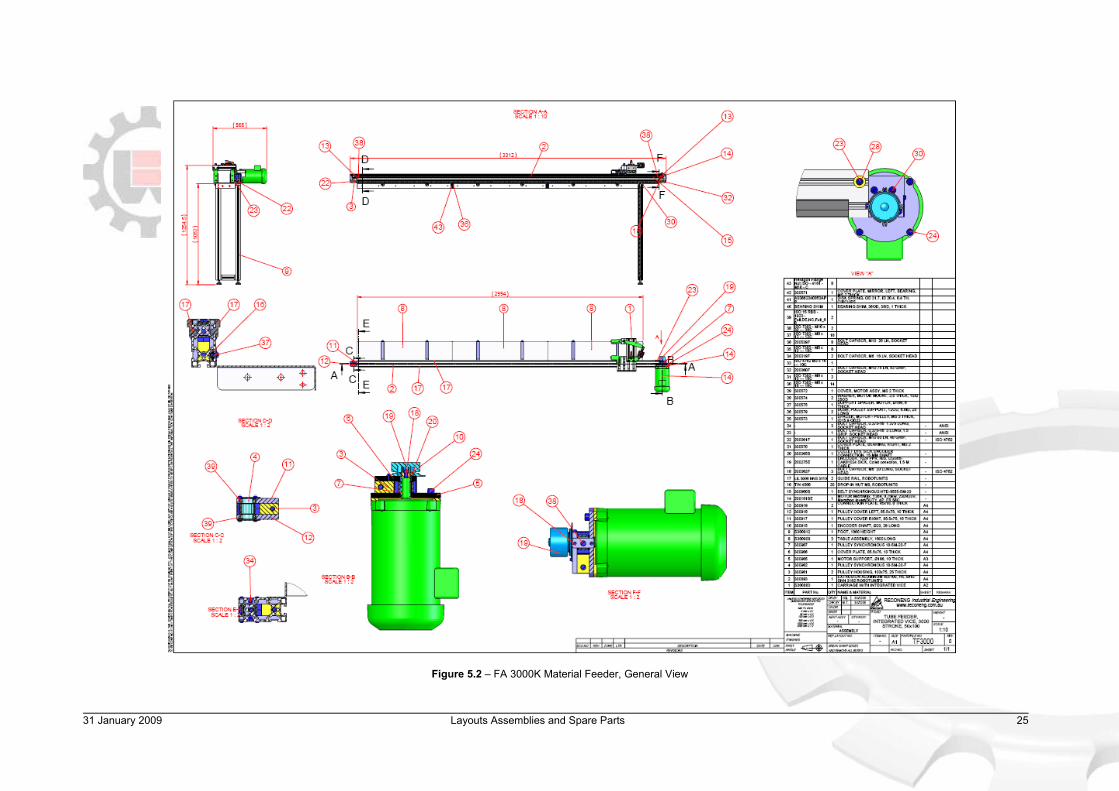
Figure 5.2 – FA 3000K Material Feeder, General View

31 January 2009 Layouts Assemblies and Spare Parts 26
Figure 5.3 – FA 3000K Material Feeder, Carriage Unit
31 January 2009 Layouts Assemblies and Spare Parts 27
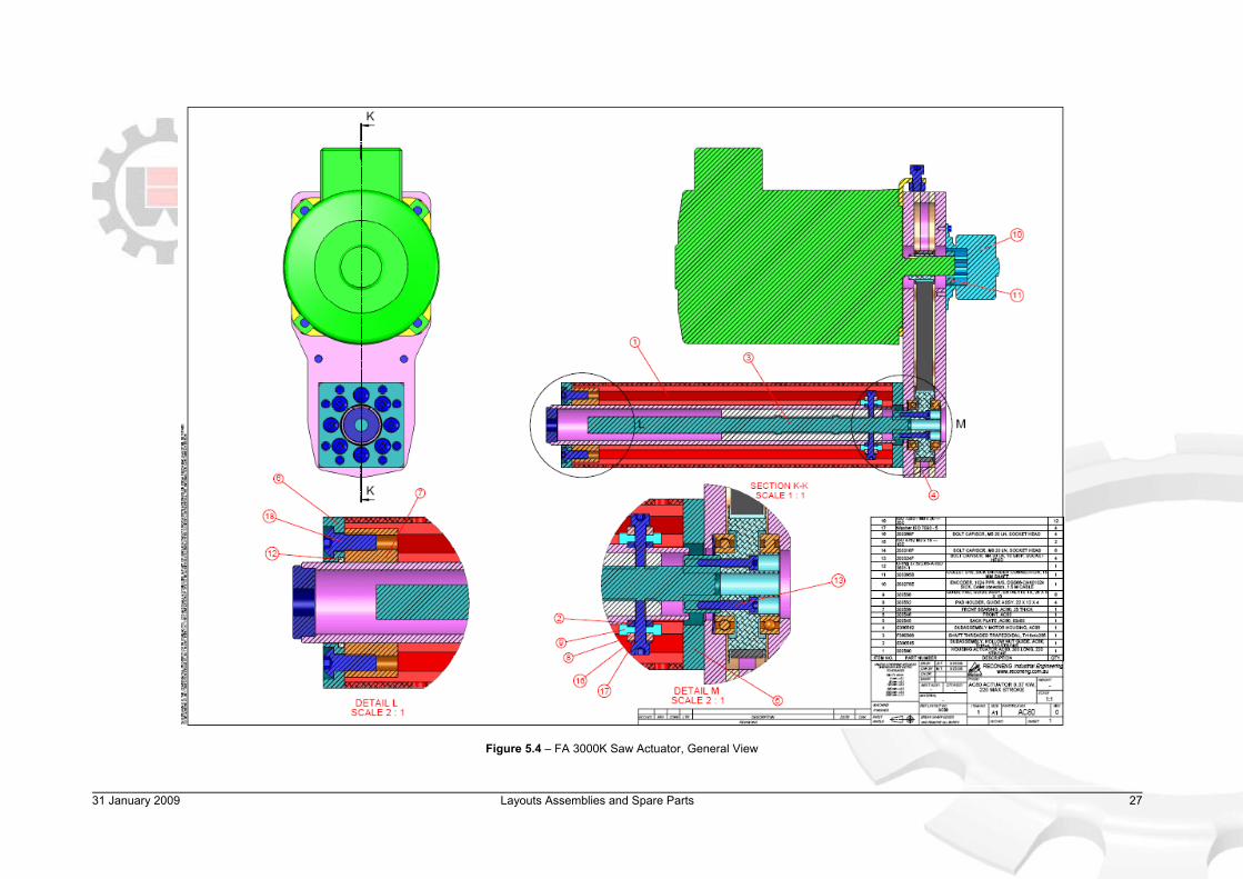
Figure 5.4 – FA 3000K Saw Actuator, General View

31 January 2009 Layouts Assemblies and Spare Parts 28
Figure 5.5 – Electrical Schematic, Power Distribution

31 January 2009 Layouts Assemblies and Spare Parts 29
Figure 5.6 – Electrical Schematic, Power Distribution

31 January 2009 Layouts Assemblies and Spare Parts 30
Figure 5.7 – Electrical Schematic, Emergency Stop Circuit

31 January 2009 Layouts Assemblies and Spare Parts 31
Figure 5.8 – Electrical Schematic, AC Main Drive

31 January 2009 Layouts Assemblies and Spare Parts 32
Figure 5.9 – Electrical Schematic, AC Actuation Drive

31 January 2009 Layouts Assemblies and Spare Parts 33
Figure 5.10 – Electrical Schematic, AC Feed Drive
31 January 2009 Layouts Assemblies and Spare Parts 34
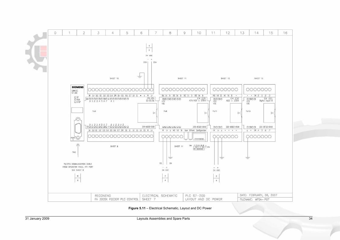
Figure 5.11 – Electrical Schematic, Layout and DC Power

31 January 2009 Layouts Assemblies and Spare Parts 35
Figure 5.12 – Electrical Schematic, Operator Panel

31 January 2009 Layouts Assemblies and Spare Parts 36
Figure 5.13 – Electrical Schematic, PLC Digital Inputs

31 January 2009 Layouts Assemblies and Spare Parts 37
Figure 5.14 – Electrical Schematic, PLC Digital Outputs

31 January 2009 Layouts Assemblies and Spare Parts 38
Figure 5.15 – Electrical Schematic, PLC Analogue Inputs
31 January 2009 Layouts Assemblies and Spare Parts 39
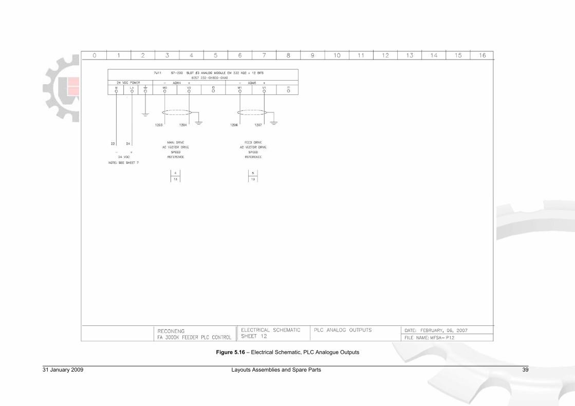
Figure 5.16 – Electrical Schematic, PLC Analogue Outputs

31 January 2009 Layouts Assemblies and Spare Parts 40
Figure 5.17 – Electrical Schematic, PLC Digital Inputs

31 January 2009 Layouts Assemblies and Spare Parts 41
Figure 5.18 – Electrical Schematic, Electrical Cabinet Gland Hole Positions

31 January 2009 Safety and Accident Prevention 42
6. SAFETY AND ACCIDENT PREVENTION
FA 3000K saw has been designed and manufactured in adherence to the applicable Australian Standards. The instructions and warnings contained in this chapter MUST be carefully followed for safe and efficient use of the machine. 6.1 Operation of the Machine
FA 3000K is designed to cut through steel components and the FA saw unit and the blade specifically selected to this end. Saw can cut through hollow and solid profiles alike, however feed rate and blade RPM appropriate to the material, size and type of the profile to cut must always be selected before cutting. The machine additionally comes equipped with an automatically retractable blade safety guard (not shown in pictures). This guard SHOULD NEVER be removed from the saw, unless changing a blade, which should be done with the machine switched off at the mains power. FA 3000K is equipped with an overload monitoring system which oversees the main motor load and, if required, actively adjusts the feed rate to reduce the load. This system significantly reduces the likelihood of damage or danger to the Operator in any case of machine malfunction or unintentional misuse. Recommended overload setting for mild steel cutting is 60 to 70 per cent although cutting large stainless steel profiles may necessitate bigger overload percentage. Cutting small-profile bars in lengths shorter than 100 mm carries risk of cuts falling in the block openings and subsequently jamming the material feeder with danger to the Operator. To cut such bars in lengths shorter than 100 mm Operator must make special considerations to ensure clearance of the cut pieces from the cutting area (Figure 6.1).
Figure 6.1 – FA 3000K Block Openings
Steel profiles to be cut often contain many dimensional imperfections and long flat profiles can often be distorted across length significantly, which increase the possibility of a mechanical jam at loader or feeder. Operator must be aware that in case of a jam, the MACHINE IS CONSTANTLY PUSHING THE PROFILE EVEN THOUGH THIS IS NOT MOVING. Hence, if the Operator attempts to release the jam without stopping the cycle, feeder will IMMEDIATELY SPRING INTO MOVEMENT, without any warning possibly putting Operator in DANGER.
Vice Openings Must be Blocked for Small-
Profile Cuts

31 January 2009 Safety and Accident Prevention 43
It is recommended that any profiles which are significantly distorted be cut manually. If a jam does occur, it is recommended only the manual clamp adjustment be attempted as an immediate remedy (as often loosening the grip will release the jam). Otherwise it is recommended the cycle is stopped immediately by pressing EMERGENCY STOP, and the profile manually unjamed through vice release and manual feeder jog back. To the right of the cutting area is the cuts collection chute, the zone in which piece to be cut is relased when completed. As the feeder moves the bar to appropriate length the bar will progressively and silently move to the right of the machine posing significant risk to anyone standing in the area unaware of this. Depending on the cut, this can be a significant length in otherwise empty space as shown in Figure 6.2. The Operator or any other personnel MUST NEVER stand in the feed exit zone while the machine is operating.
Figure 6.2 – Exit Feed Danger Zone
6.2 Safety Notes
FA 3000K is a high-powered saw unit performing high-speed cutting of steel brackets. Extreme caution is required when operating the device. The machine operator must be perfectly aware of the position and functions of all the machine’s controls outlined in this manual. The Employer is responsible for adequately instructing the Operator on any accident risks, safety devices and noise emissions, in addition to being aware of, and implementing, the accident prevention regulations provided for by the National and International laws governing the use of the machine. Under normal usage, machine will require minimum maintenance, provide long blade life and cause minimum residual noise. If in doubt about any functional or modification issues, consult Brobo Waldown Engineering Department. All those concerned must strictly adhere to all instructions, warnings and accident prevention standards in this manual.
No personnel allowed in the end-feed zone when machine is in operation.
31 January 2009 Safety and Accident Prevention 44
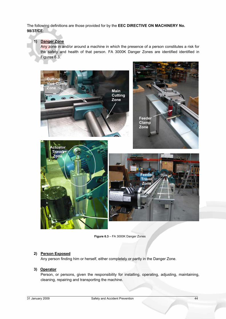
The following definitions are those provided for by the EEC DIRECTIVE ON MACHINERY No. 98/37/CE:
1) Danger Zone Any zone in and/or around a machine in which the presence of a person constitutes a risk for the safety and health of that person. FA 3000K Danger Zones are identified identified in Figures 6.3.
Figure 6.3 – FA 3000K Danger Zones
2) Person Exposed Any person finding him or herself, either completely or partly in the Danger Zone.
3) Operator
Person, or persons, given the responsibility for installing, operating, adjusting, maintaining, cleaning, repairing and transporting the machine.
Main Cutting Zone
Cutting Vice Clamp Zone
Feeder Clamp Zone
Feeder Travel Zone
Actuator Travel Zone

31 January 2009 Safety and Accident Prevention 45
6.2.1 Noise Level
The noise level of an idling unit has been measured below 85 dBA. This complies with the Australian Occupational Health and Safety (Noise) Regulations 1992.
Please note, saw noise levels when cutting are higher than idling. The noise level will vary according to the sharpness of the blade. Management should make available to the Operator(s) appropriate hearing protection as prescribed under the State Act, if necessary. 6.2.2 Power Supply
The machine uses high-voltage 415 V (3 phase) or 240 V (1 phase) power supply and any unauthorised interference and / or inadequate maintenance could put the Operator or Person Exposed at risk. A qualified electrical engineer should be assigned to maintain and repair the system. Check that the power supply cables comply with, and are operating within the acceptable range of the saw capabilities. Faulty, damaged or worn components must be replaced immediately. Installation of the earthing system must comply with the requirements stated in the IEC Standards Part 195: Earthing and Protection Against Electric Shocks 1998. 6.2.3 Lighting Insufficient lighting during cutting would constitute a safety hazard for the Operator and Person Exposed. For this reason, the user of the machine must have access to adequate lighting in the working area, while also preventing dazzling illumination sources (Reference standard ISO 8995 - 2002 ‘Lighting of Indoor Workplaces’). 6.3 Advice for the Operator
Protective eyewear or goggles must be worn at all times while attending and operating the saw.
Do not attempt to operate the machine unless all safety guards are in operation. The guard must fully cover the blade when the head is in the uppermost position.
Ensure that hands and arms are kept well clear of the cutting zone when the machine is operating.
Do not wear oversize clothing with long sleeves, oversize gloves, bracelets, necklaces or any other loose object that may become entangled in the machine’s blade during cutting. Long hair must be tied back or placed in a hair net.
31 January 2009 Safety and Accident Prevention 46
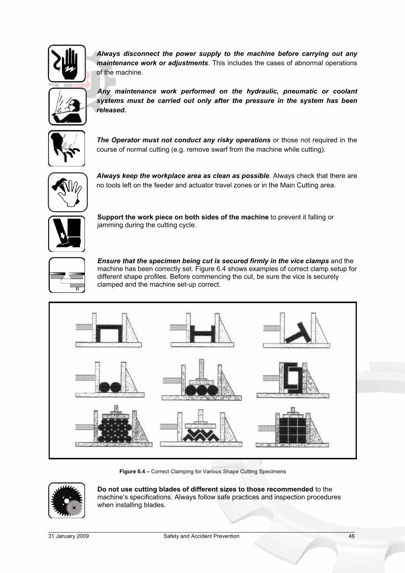
Always disconnect the power supply to the machine before carrying out any
maintenance work or adjustments. This includes the cases of abnormal operations of the machine.
Any maintenance work performed on the hydraulic, pneumatic or coolant systems must be carried out only after the pressure in the system has been released.
The Operator must not conduct any risky operations or those not required in the course of normal cutting (e.g. remove swarf from the machine while cutting).
Always keep the workplace area as clean as possible. Always check that there are no tools left on the feeder and actuator travel zones or in the Main Cutting area.
Support the work piece on both sides of the machine to prevent it falling or jamming during the cutting cycle.
Ensure that the specimen being cut is secured firmly in the vice clamps and the machine has been correctly set. Figure 6.4 shows examples of correct clamp setup for different shape profiles. Before commencing the cut, be sure the vice is securely clamped and the machine set-up correct.
Figure 6.4 – Correct Clamping for Various Shape Cutting Specimens Do not use cutting blades of different sizes to those recommended to the machine’s specifications. Always follow safe practices and inspection procedures when installing blades.

31 January 2009 Safety and Accident Prevention 47
When cutting very small specimens, ensure that the workpiece is not dragged behind the back fence support, where it could get lodged behind the blade. If the blade becomes jammed, stop the saw immediately. Use manual jog backward to release the specimen.
Always turn off the machine before carrying out any repair work. Consult the Brobo Waldown Engineering Department for any assistance.
6.4 Reference Standards The following general standards, applicable to the FA 3000K saw, are those specified by the EEC Committee that governs the safety of machinery, health and safety at work, personal protection and safeguarding of the work environment. In addition, the FA 3000K also complies with the Australian Standards regarding safeguarding and general requirements for electrical equipment:
1) EEC Directive No. 98/37/CE - Machines Directive 2) EEC Directive No. 91/368 - 94/68 - Amends sections of EEC Directive No. 98/37/CE relating
to machine safety
3) EEC Directive No. 73/23 - Low Voltage Directive
4) AS4024.1 - 1996 - Safeguarding of Machinery The following applicable standards relate to Health and Safety at work:
1) AS3100 - 2002 - General Requirements for Electrical Equipment 2) Operational Health and Safety (OHS) 1995.81/1995 - Compliance References
3) EEC Directive No. 80/1107; 83/477; 86/188; 88/188; 88/642 - Protection of Workers against
risks caused by exposure to physical, chemical and biological agents in workplace
4) EEC Directive No. 73/23 and Special EEC Directives No. 89/654; 89/655 - Improvements in health and safety at work

31 January 2009 Troubleshooting Guide 48
7. TROUBLESHOOTING GUIDE 7.1 General Troubleshooting Table 7.1 illustrates a list of some of the most common problems associated with FA 3000K saw and the recommended troubleshooting procedures. If the solutions provided do not resolve the problems, or the problem identified differs from those listed, contact Brobo Waldown Engineering Department. Always disconnect the machine at the Main Power switch before attempting any fix.
PROBLEM IDENTIFIED DIAGNOSIS SOLUTIONS
Electrical Power Supply not Connected. Ensure that the main power cable is plugged in and switched on.
No Power
Main Switch not on. Check the phases, cables, plugs and sockets for loose connection.
Emergency Stop pressed Process won’t start after
powering up Electrical Fuse Blown
Check that there is no emergency stop buttons activated or replace any blown fuses.
Feeder won’t move when Homing or otherwise under
command
Feeder not activated by Feeder Engage button.
Check and press Feeder Engage button.
Error screen “Actual Count Equal to Set” comes up.
The machine has either completed a cutting job or cutting has reached the
previous count set in memory.
Go to New Jobs screen and either reset the counter or set it to a higher number.
Machine suddenly starts after a mode is switched on the
Home scroll screen
Machine was previously switched modes without the previous mode process being
stopped or a manual control of some function was left on.
Always reset the machine at the Home screen Stop/RST button and ensure any manually switched on processes are turned off before changing modes.
Excessive heat, sparks or smoke during cutting Blade RPM or feed rate set too high Set saw rotational speed appropriate
for the cut, between 30 to 90 RPM.
Overload monitoring actively controlling the feed. Normal Operation
Main Motor torque limit exceeded
If Overload monitoring system not active, check that saw motor is not experiencing any extraordinary load, or decrease feed speed.
Mechanical Jam Check that there is no mechanical jam and the movement of saw head is free.
Main motor struggles or stops (feed or blade)
Dull Blades Re-sharpen or replace blades on the unit.
Table 7.1 – General Troubleshooting Guide
94 secidneppA 9002 yraunaJ 13
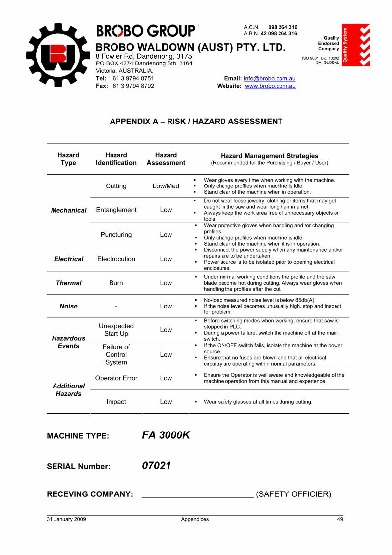
APPENDIX A – RISK / HAZARD ASSESSMENT
Hazard Type
Hazard Identification
Hazard Assessment
Hazard Management Strategies (Recommended for the Purchasing / Buyer / User)
Cutting Low/Med Wear gloves every time when working with the machine. Only change profiles when machine is idle. Stand clear of the machine when in operation.
Entanglement Low Do not wear loose jewelry, clothing or items that may get
caught in the saw and wear long hair in a net. Always keep the work area free of unnecessary objects or
tools.Mechanical
Puncturing Low Wear protective gloves when handling and /or changing
profiles. Only change profiles when machine is idle. Stand clear of the machine when it is in operation.
Electrical Electrocution Low Disconnect the power supply when any maintenance and/or
repairs are to be undertaken. Power source is to be isolated prior to opening electrical
enclosures.
Thermal Burn Low Under normal working conditions the profile and the saw
blade become hot during cutting. Always wear gloves when handling the profiles after the cut.
Noise - Low No-load measured noise level is below 85db(A). If the noise level becomes unusually high, stop and inspect
for problem.
Unexpected Start Up Low
Before switching modes when working, ensure that saw is stopped in PLC.
During a power failure, switch the machine off at the main switch. Hazardous
Events Failure of ControlSystem
Low If the ON/OFF switch fails, isolate the machine at the power
source. Ensure that no fuses are blown and that all electrical
circuitry are operating within normal parameters.
Operator Error Low Ensure the Operator is well aware and knowledgeable of the machine operation from this manual and experience.
Additional Hazards
Impact Low Wear safety glasses at all times during cutting.
MACHINE TYPE: FA 3000K
SERIAL Number: 07021
RECEVING COMPANY: (SAFETY OFFICIER)
BROBO WALDOWN (AUST) PTY. LTD.
A.C.N. 098 264 316 A.B.N. 42 098 264 316
65-67 Williams Rd, Dandenong, 3175 PO BOX 4274 Dandenong Sth, 3164 Victoria, AUSTRALIA. Tel: 61 3 9794 8751 Email: [email protected] Fax: 61 3 9794 8792 Website: www.brobo.com.au
Quality Endorsed Company
ISO 9001 Lic. 10292
SAI GLOBAL Qu
alit
y S
yste
m
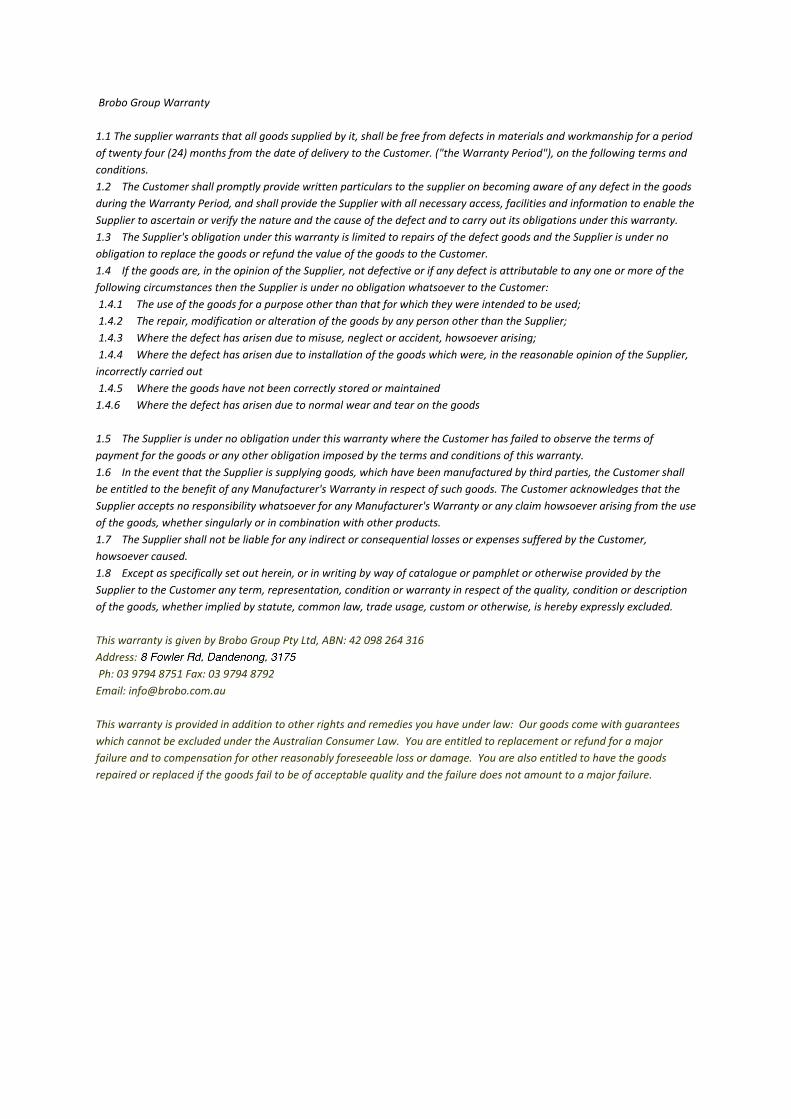
Brobo Group Warranty 1.1 The supplier warrants that all goods supplied by it, shall be free from defects in materials and workmanship for a period of twenty four (24) months from the date of delivery to the Customer. ("the Warranty Period"), on the following terms and conditions. 1.2 The Customer shall promptly provide written particulars to the supplier on becoming aware of any defect in the goods during the Warranty Period, and shall provide the Supplier with all necessary access, facilities and information to enable the Supplier to ascertain or verify the nature and the cause of the defect and to carry out its obligations under this warranty. 1.3 The Supplier's obligation under this warranty is limited to repairs of the defect goods and the Supplier is under no obligation to replace the goods or refund the value of the goods to the Customer. 1.4 If the goods are, in the opinion of the Supplier, not defective or if any defect is attributable to any one or more of the following circumstances then the Supplier is under no obligation whatsoever to the Customer: 1.4.1 The use of the goods for a purpose other than that for which they were intended to be used; 1.4.2 The repair, modification or alteration of the goods by any person other than the Supplier; 1.4.3 Where the defect has arisen due to misuse, neglect or accident, howsoever arising; 1.4.4 Where the defect has arisen due to installation of the goods which were, in the reasonable opinion of the Supplier, incorrectly carried out 1.4.5 Where the goods have not been correctly stored or maintained 1.4.6 Where the defect has arisen due to normal wear and tear on the goods 1.5 The Supplier is under no obligation under this warranty where the Customer has failed to observe the terms of payment for the goods or any other obligation imposed by the terms and conditions of this warranty. 1.6 In the event that the Supplier is supplying goods, which have been manufactured by third parties, the Customer shall be entitled to the benefit of any Manufacturer's Warranty in respect of such goods. The Customer acknowledges that the Supplier accepts no responsibility whatsoever for any Manufacturer's Warranty or any claim howsoever arising from the use of the goods, whether singularly or in combination with other products. 1.7 The Supplier shall not be liable for any indirect or consequential losses or expenses suffered by the Customer, howsoever caused. 1.8 Except as specifically set out herein, or in writing by way of catalogue or pamphlet or otherwise provided by the Supplier to the Customer any term, representation, condition or warranty in respect of the quality, condition or description of the goods, whether implied by statute, common law, trade usage, custom or otherwise, is hereby expressly excluded. This warranty is given by Brobo Group Pty Ltd, ABN: 42 098 264 316 Address: 65‐67 Williams Rd, Dandenong, VIC 3175 Ph: 03 9794 8751 Fax: 03 9794 8792 Email: [email protected] This warranty is provided in addition to other rights and remedies you have under law: Our goods come with guarantees which cannot be excluded under the Australian Consumer Law. You are entitled to replacement or refund for a major failure and to compensation for other reasonably foreseeable loss or damage. You are also entitled to have the goods repaired or replaced if the goods fail to be of acceptable quality and the failure does not amount to a major failure.