faa order 6740.6 - u.s. national aviation standard for the ... · order 1 6740.6 u.s. national...
TRANSCRIPT

ORDER 1 67406
US NATIONAL AVIATION STANDARD FOR THE NDBADF SYSTEM
12 fJ87
DEPARTMENT OF TRANSPORTATION FEDERAL AVIATION ADMINISTRATION
Distribution A-W( FSWSPOIAEUESPMTOTR)-3 A-W(VN )-2 Initiated By AES-31 0 A-X(AF)-3 A-Z-3 A-FAF-0
123087 67406
FOREWORD
During the early 1960s many thought that NDBs would disappear with the wide implementation of VORDMETACAN However while the NDB has evolved from a primary to a secondary navigation aid it has hardly disappeared Quite to the contrary it now outnumbers VOR stations by a factor of more than 2 to 1 No end of service is foreseen between now and the year 2000 because of the wide and increasing acceptance by aviation users and the lack of an acceptable replacement system
The NDBADF System like most aeronautical systems will continue to evolve in response to user needs The number of FAA NDBs will remain stable and future growth primarily will be non-Federal in nature As the system evolves proper operation and compatibility among elements of the system must be maintained This order is intended to provide guidance in this endeavor
Under the Federal Aviation Act of 1958 as amended 49 USC Section 1301 et seq the FAA is charged with providing for the regulation and promotion of civil aviation in order to best foster its development and safety and to provide for the safe and efficient use of the airspace by both civil and military aircraft Explicitly the Administrator shall develop modify test and evaluate systems procedures facilities and devices defining their performance characteristics as needed This effort is directed toward meeting the need for safe and efficient navigation and traffic control of all civil and military aircraft operating in a common civilmilitary National Airspace System
-middot -
~~ Administrator
Page i (and iil
123087 6 7 40 6
TABLE OF CONTENTS
Page No
CHAPTER 1 GENERAL 1
1 Purpose 1 2 Distribution 1 3 Definitions 1 4 Authority to Change This Order 1 5 Applicability 1 6 The NDBADF System Characteristics 1 7-19 Reserved 2
CHAPTER 2 NDB ADF SYSTEM 5
20 NDBADF System Description 5 21 Rated Coverage Volume 5 22 Effective Coverage Volume 5 23 Operational Service Volume 5 24 Standard Service Volumes 5
Figure 2-1 NDB Service Volume Ranges 5 25 Service Limitations Due to Ionospheric
Reflections 6 26 Radiofrequency (RF) Allocations 6 27 Frequency Congestion 7 28 Station Passage 7 29 Station Identification Code Characteristics 7 30 Identification Code 8 31 Station Voice Transmissions 8 32 Airborne Components 8 33 NDBADF-Bearing Accuracy 8 34 Use of Other Than NDB Ground Stations 9 35 En Route Use of NDBs 9 36 Use of an NDB as a Compass Locator (COMLO) 9 37 Nonprecision Approach NDB Location 9 38 Flags and Warnings 9 39 Pilot Monitoring During Use 10 40-59 Reserved 10
Page iii
67406 123087
Page No
CH~PTER 3 OPE~TION~L CH~~~CTERISTICS OF NOB GROUND 17 ST~TIONS
60 Introduction 17 61 Emission Characteristics 17 62 Frequency Tolerance 17 63 Field Strength 17 64 Power Limitations 18 65 Single Carrier NOBs 18 66 Dual Carrier NDB 1 s 18 67 Identification Code Modulations 18 68 Monitoring 18 69 Grounding 18 70-89 Reserved 18
CH~PTER 4 OPER~TION~L CH~R~CTERISTICS FOR ~DF COMPONENTS 23
90 Introduction 23 91 Receiver Sensitivity 23 92 Receiver Selectivity 23
Figure 4-l Current ADF Receiver Selectivity 23 Figure 4-2 Future AOF Receiver SeLectivity 24
93 Station Identification 24 94 Bearing Information 24 95 Bearing ~ccuracy 24 96 Radiation 24 97 DeVelopment of Flag and tJarning Functions 24
~PPENDIX l DEFINITIONS ~ND ~CRONYMS (2 Pages) 1
~PPENDIX 2 SYSTEM BE~RING ~CCU~CY (3 Pages) l Figure l Combined Error Determination 2
~PPENDIX 3 NOB FREQUENCIES 1
Page iv
l~~087 67406
CHAPTER 1 GENERAL
1 PURPOSE This order establishes the Nondirectional Beacon (NDB) Automatic Direction Finder (ADF) US National Aviation Standard defining the performance required of the system and its components This standard defines the application and performance characteristics as well as some operational limitations and restrictions for NDB and ADF equipment in the United States For ground and airborne components this material identifies signal functional and performance characteristics required to meet operational requirements and to provide compatibility between components of the system
2 DISTRIBUTION This order is distributed to branch level in the Offices of Flight Standards Airworthiness Aviation Policy and Plans International Aviation Europe Africa and Middle East Office Systems Engineering Service Program Engineering and Maintenance Service Air Traffic Operations Service and Air Traffic Plans and Requirements Service division level in the Aviation Standards National Field Office branch level in the regional Airway Facilities Divisions and the FAA Technical Center and to the Airway Facilities Field and Sector Offices
3 DEFINITIONS Appendix 1 Definitions and Acronyms contains the definitions and acronyms used in this order
4 AUTHORITY TO CHANGE THIS ORDER The Director Systems Engineering Service may issue changes to this order The Administrator reserves the authority to approve changes which establish policy delegate authority or assign responsibility
5 APPLICABILITY The National standard applies to all NDB ground equipment and ADF airborne equipment used in the National Airspace System (NAS)
6 THE NDBADF SYSTEM CHARACTERISTICS
a The ADF component characteristics apply in entirety to those components used in aircraft operations performed under Instrument Flight Rules (IFR) However for other aircraft operations the applicability is limited to requirements identified in chapter 4 as essential to prevent impairment of services to other NAS users
b In all cases where a parameter and associated tolerance is identified herein ground stations shall be maintained within these limits by quality assurance methods including monitoring periodic ground or flight inspections or a combination of these methods
c Operators of airborne systems designed installed and operated in accordance with this order can expect to achieve the system performance which the order js designed to provide
Chap 1 Par l Page l
67406 123087
d It is recognized that certain existing NDB equipment characteristics may not comply with all requirements of this order Specific NDB equipment characteristics that are identified which deviate from the requirements of this order will be corrected or replaced as practical but not later than l year from the date of this order unless a waiver is authorized by the cognizant regional office
7-19 RESERVED
Chap Page 2 (thru 4) Par 6
l
123087 67406
CHAPTER 2 NDB ADF SYSTEM
20 NDBADF SYSTEM DESCRIPTION Tne NDBADF System is a snort distance air navigation system The ground component provides properly equipped aircraft with bearing and identification referenced to the selected ground component The system provides navigation signals to all civil and military aviation for the safe and efficient conduct of aircraft operations exercise of air traffic control and use of airspace The NOB is an International Civil Aviation Organization standard navigation aid The NOBADF System nas been allocated radio spectrum in the aeronautical radionavigation service The primary purpose of the NDBADF System is for navigation While other services may be provided by the system they are less important than the navigation inforshymation The identification signal is an integral part of the navigation signal since without the identification the navigation information cannot be validated
21 RATED COVERAGE VOLUME Rated coverage is the volume of airspace around an NOB within whicn the strength of the vertical field of the groundwave meets or exceeds the minimum field strength as specified in paragraph 63a
22 EFFECTIVE COVERAGE VOLUME Effective coverage is tne volume of airspace around an NOB within which bearings can be obtained with a total system accuracy of 10 degrees to the right or left of course In general a facilitys effective coverage volume is smaller than the rated coverage volume
23 OPERATrONAL SERVrCE VOLUME Operational coverage is tne volume of airspace around an NDB which is advertised by the FAA as available for airborne use The operational coverage shall not exceed the rated coverage or the effective coverage on any azimutn or at any elevation NOBs are available for use within their operational service volumes Outside this airspace reliable service may not be available
24 STANDARD SERVICE VOLUMES NOBs are classified according to their intended use The ranges of NDB service volumes are sho~n in figure 2-1 The distances (radius) are tne same at all altitudes
FIGURE 2-l NOB SERVICE VOLUME RANGES
CLASS orsTANCE (RADIUS)
COMLO 15 nmi MH 25 nmi H 50 nmi HH 75 nmi
NOTE Service volume ranges of individual facilities may be less than that indicated Restrictions to service volumes are first publisned in the Notice to Airmen (NOTAM) and tnen with tne alphabetical listing of tne navigation aid (NAVAID) in tne AirportFacility Directory
Cnap 2 Par 20 Page 5
6 7 40 6 123087
25 SERVICE LIMITATIONS DUE TO IONOSPHERIC REFLECTIONS ow fre0ency (LF) radiation propagates both as a groundwave and as a skywave The groundwave is used for navigation The skywave is generally un~e1ia~le fo~ navigational use due to bearing inaccuracies A given NOB 1 s g-oundwave is so2~tines
simultaneously receivable with a skywave which can cause interference and degrade or make unusable the navigation signal This inte~erence can occur in two ways called night effect and skywave interference
a Skywave interference is a situation in which any skywave is large enough to interfere with a given NDBs groundwave At night the reflective properties of the ionosphere increase and the skywave can be substantially larger than during the day When a skywave is large enough to interfere with a groundwave this situation is aptly called skywave interference When the skywave of a facility interferes with its own groundwave this type of skywave interference is called night effect bullbull Skywave interference is subject to diurnal seasonal and irregular changing properties of the ionosphere It is not possible to predict precisely when and where skywave interference will occur or the severity of its effect on the NDBADF System operations Skywave interference manifests itself in one or more of the following ways erroneous bearings hunting of the ADF needle garbling of the identification signal andor the presence of atore than one identification signal Skywave interference is most likely to occur from shortly before sundown until shortly after sunrise
b Night effect is a situation in which the groundwave and skywave of a given NDB are simultaneously receivable at large distances from the NDB Tflhen this occurs it is unlikely that reliable bearings can be obtained if the groundwave does not exceed the skywave by at least 10 decibels (dB) In most cases this is not an operational concern because NDBs are generally used at short ranges as terminal or transition facilities At short range night effect is not a problem At very long ranges however night effect can present bearing accuracy problems Therefore the maximum operational service volume shall not extend beyond the range where the groundwave will exceed the skywave by 10 dB The maximum allowable range is dependent on the NDB frequency and on ground conductivity However it is independent of NDB power since increasing the transmitter power increases both the groundwave and the skywave
26 RADIOFREQUENCY (RF) ALLOCATIONS The NDBADF System is allocated radio spectrum in the aeronautical radionavigation service Specific frequencies allocated for NDBADF use are listed in Appendix 3 NDB Frequencies
Chap 2 Page 6 Par 25
12jiJ87 67406
27 FREQUENCY CONGESTION
a Background During the 1975-1985 time period there was a dramatic growth in the number of NDBs Of the more than 2000 NOBs in this country over two-thirds are non-Federal ground stations Growth in the number of non-Federal systems has been many times larger than growth in the number of Federal systems This trend is expected to continue Eventually the NDBADF System will be replaced however at this time the replacement system has not been identified No end of service can be foreseen in this century because of the wide and increasing user acceptance and the lack of an acceptable proven replacement system
b Congestion NDB frequency congestion has been a longstanding problem both in this country and in Europe In the United States congestion is most severe in California along the East Coast and along the Gulf of Mexico In these and other areas frequency congestion makes it difficult or impossible to make frequency assignments for new NDBs In an effort to alleviate this problem the FAA requested that the Radio Technical Commission for Aeronautics (RTCA) form a special committee to develop and recommend improved ADF standards This effort was completed and the resulting standards were published in 1982 In the long term the tighter selectivity of such avionics will provide some relief to the congestion problem In the near term however frequency congestion will continue to constrain the number of new NDB assignments which can be made
28 STATION PASSAGE The sharp reduction in signal strength directly over the station known as the cone of confusion or cone of silence shall not exceed a total of 40 degrees (ie ~20 degrees as measured from the vertical above the NDB)
29 STATION IDENTIFICATION CODE CHARACTERISTICS Each NDB shall transmit an identification signal in International Morse Code at least three times each 30 seconds equally spaced within that interval Voice identification shall not be permitted The characteristics of the identification code shall be as follows
a The dots shall be a time duration of 01 second to 0125 second and the dashes shall be three times the duration of a dot
b The time between dots and dashes of a code letter shall be the length of a dot
c The time between consecutive letters of the identification code group shall be the length of three (3) dots
Chap 2 Par 27 Page 7
67406 123087
30 IDENTIFICATION CODE The NDB identification code shall be as follows
a Standard Identification Code With the exception of the two cases outlined in subparagraphs band c all NDBs shall transmit a three-letter identification code This code shall be transmitted at intervals equal to sixty-four (64) dot lengths
b Compass Locator (COMLO) COMLOs shall transmit a two-letter identification code derived from the identification code of the instrument landing system (ILS) with which it is associated The identification code shall be transmitted at intervals equal to forty-eight (48) dot lengths
c IDBs That Are Not Part of the NAS With NDBs that are not a part of the NAS it is permissible to add one digit to the standard three-letter identific3tion code This four-character code (three letters one number) shall be transmitted at intervals equal to eighty 80) dot lengths
d Code Suppression The NDB identification code shall not be suppressed during voice transmissions
e Absence of Identification The absence of an identification code shall serve as an indication that the NDB is unusable or out of service
31 STATION VOICE TRANSMISSIONS The NDB can be used as an outlet for automated weather observing system and other weather system broadcasts until an alternate method of disseminating this information becomes available However the primary purpose of NDB 1 s is to provide middotnavigational aid and therefore NDBs should not be retained solely to satisfy voice broadcast requirements The quality of voice transmission from an NDB can be a problem because of antenna bandwidth limitations and susceptibility to noise from manmade and natural sources When installed NDB voice coverage will be usable to at least two-thirds of the rated service volume
32 AIRBORNE CO~PONENTS Airborne components of the system consist of ADF equipment which conforms to the requirements of chapter 4 of this order
33 NDBADF-BEARING ACCURACY The basic purpose of an NDB is to allow an AUF-equipped aircraft to fly from point A to point B and to stay within a defined airspace in the process For terminal and transition NDB 1 s this airspace is the obstacle clearance zone This zone is based on NDB- and ADFshybearing accuracy The total system accuracy is approximately +10 degrees See appendix 2)
Chap 2 PqeB Par 30
123087 67406
34 USE OF OTHER THAN NDB GROUND STATIONS In addition to NDBs ADF receivers can also receive and process signals from amplitude modulation (AM) broadcast stations maritime radio beacons and several other types of stations Pilots have used such stations as aids during a visual flight rules (VFR) flight for a long time However these stations are neither flight inspected nor a part of the NAS A VFR flight using such ground stations as a sole means of navigation is uncertified pilots fly at their own risk An IFR flight using such ground stations shall not be permitted
35 EN ROUTE USE OF NDBS Except as noted in subparagraphs a b and c NDBs will not be used as en route navigation aids
a NOBs may be used as en route aids in Alaska when other NAVAID 1 s are unavailable Airspace protection shall be increased to compensate for the accuracy limitations in such cases
b NDBs may be used on a temporary basis as substitute NAVAID 1 s to support an air route when a Very High Frequency Omnidirectional Radio Range is out of service
c NDBs may be used together with Distance Measuring Equipments for the air route structure system This may include terminal approaches in Alaska
36 USE OF AN NDB AS A COMLO When an NDB is colocated with a marker beacon and used in conjunction with an ILS it is commonly referred to as a COMLO Where a COMLO is used as a supplement to an ILS it should be located at the outer marker beacon site Due to the frequency congestion in the LF and medium frequency bands use of a COMLO at the middle marker in addition to one at the outer marker is not recommended
37 NONPRECISION APPROACH NDB LOCATION Where an NDB serves as a final approach fix in the absence of an ILS the NDB should be located at a site equivalent to an outer marker site Site selection shall take into account the appropriate obstacle clearance requirements
38 FLAGS AND WARNINGS Unlike most navigation aids the NDBADF System generally does not provide a warning or a flag if the received signal is deficient in level or quality The pilot must determine whether the received signal is reliable by listening to the identification and observing the needle movements The reception of two different identification signals simultashyneously or the lack of any identification means that the ADF bearing is unreliable Similarly unusual needle variations are also an indication of unreliable bearing Since the NDBADF System provides no other warning or flag the pilot must monitor both station identification and ADF needle variation while making use of the NDBADF System
1
Chap 2 Par 34 Page 9
67406 12 JJ87
39 PILOT MONITORING DURING USE ADF navigation requires that the pilot monitor the audio output of the ADF receiver (ie the NDB identification and all other received signals including background noise) and the needle action of the bearing indicator Whenever there is a question as to the reliability of the NDB signal the pilot should switch to another form of navigation There are some potential problems of which the pilot should be aware such as RF interference from other NOBs skywave interference (paragraph 25) and adverse ~7eather and precipitation static (p-static) Adverse 11eather and p-static can affect the reception of NDB signals This is caused primarily by thundershystorms frictional charging from neutral snow ice dust or particles in the atmosphere and engine charging The duration of these effects can be momentary or they can last for the duration of the flight
40-59 RESERVED
Chap 2 Page 10 ( thru 16) Par 39
123087 67406
CHAPTER 3 OPERATIONAL CHARACTERISTICS OF NDB GROUND STATIONS
60 INTRODUCTION This chapter identifies signal characteristics and tolerances of the NDB ground station This chapter represents performance that shall be provided throughout the operational service volume
61 EMISSION CHARACTERISTICS The mean power of any unwanted emissions supplied to the antenna transmission line as compared with the mean power of the fundamental shall be in accordance with the following
a On any frequency removed from the assigned frequency by more than 100 percent up to and including 150 percent of the authorized bandwidth at least 25 dB attenuation
b On any frequency removed from the assigned frequency by more than 150 percent and up to and including 300 percent of the authorized bandwidth at least 35 dB attenuation
c On any frequency removed from the assigned frequency by more than 300 percent of the authorized bandwidth~ for transmitters with mean power of 5 kilowatts or greater at least 80 dB attenuation and for transmitters with mean power less than 5 kilowatts at least 43 plus 10 log10 (mean power of the fundamental in watts) dB attenuation ie 50 microwatts absolute level
62 FREQUENCY TOLERANCE The frequency tolerance of the NDB carrier shall comply with the following
a The RF carrier of all stations shall be within 001 percent of the assigned frequency
b With dual carrier NOBs the requirements of this paragraph refer to the continuous carrier as opposed to the keyed carrier that provides the station identification
63 FIELD STRENGTH
a Minimum Field Strength Throughout the operational coverage volume the minimum field strength shall not be less than 50 microvolts per meter (uvm) which is the minimum value allowed at the alarm point This is equivalent to 70 uvm at peak power (50 uvm = 34 dBuvm 70 uvm = 37 dBuvm) dBuvm are dBs with respect to one microvolt
b Flight Inspection Guidance Minimum field strength settings will be based on flight inspection guidance Correlation of flight inspection results will be made with the measurements of antenna current and impedance made by the maintenance technician during routine checks of the facility Also the selection of airborne locations and times that the field strength is measured is important in order to avoid abnormal results for the locality concerned locations on air routes in the area around the beacon are operationally most significant
Chap 3 Par 60 Page 17
57406 123087
64 POWER LIMITATIONS NDB radiated power shall not exceed by more than 2 dB that power which is necessary to provide a field strength of 70 uvm at peak power throughout the operational service volume (see paragraph 63a)
65 SINGLE CARRIER NDBS A single carrier NDB is a double sideband sys tern It r ad ia tes a continuous wave ( CV) carrier on the assigned frequency The identification signal is provided by keyed AM of the carrier frequency The emission designator is 2K04A2A for a single carrier NDB with 1020 Hz modulation The emission designator is 800HA2A for a single carrier NDB with 400 Hz modulation
56 DUAL CARRIER NDBS A dual carrier NDB is a single sideband system (full carrier) It radiates a CW carrier on the assigned frequency The identification signal is provided by onoff keying of a second carrier This second carrier is transmitted at a frequency equal to the carrier frequency plus the frequency of the modulation tone For example at a carrjer frequency of 200kHz the second carrier would be approximately 2004 kHz (400Hz identification) or 20102 kHz (1020Hz identification) The emission designator is 1Kl2XXA for a dual carrier NOB with 1020 Hz modulation The emission designator is SOOHXXA for a dual carrier NDB with ~00 Hz modulation
67 IDENTIFICATION CODE MODULATIONS The characteristics of the identification code shall conform to the following
a Modulation Frequency The modulation frequency shall be either 400 +25Hz or 1020 +50 Hz
b Depth of Modulation The depth of modulation of the carrier of an NDB should be as great as pqssible Ninety-five percent modulation as measured at the transmitter should be a goal This goal is dependent upon the antenna systems frequency bandwidth frequency of the modulation signal and the condition of the antenna ~ith these constraints conSidered the modulation level should be as great as practical without distorting the navigation or identification signal
68 MONITORING The radiated signal shall be monitored and removed from service upon recognition of unsafe operations
69 GROUMDING Frequency planning is done on the assumption that the field strength and the equivalent isotropic radiated power (bullEIRP) will be maintained within the proper tolerances If the grounding resistance is high (due to insufficient grounding) the radiation efficiency will be lower and the EIRP will have an increased sensitivity to changes in climatic conditions and other factors Consequently in all cases the grounding system should be the best possible taking into account local circumstances
70-89 RESERVED
Chap 3 Page 18 (thru 22) Par 64
123087 67406
CHAPTER 4 OPERATIONAL CHARACTERISTICS FOR ADF COMPONENTS
90 INTRODUCTION This chapter specifies the functional capability and performance characteristics required of the ADF component The term component describes the complete aircraft installation This includes the antenna and its transmission line the receiver electrical power source(s) identification signal reproduction devices and the bearing indicator~ Airborne components used in IFR operations must meet all Federal Aviation Regulation requirements For non-IFR operations the requirements are limited to those of paragraphs 91 through 96 Components should be capable of performing as specified throughout the operational service volume The applicable performance requirements should be met when the ground stations are operating in accordance with this order
91 RECEIVER SENSITIVITY Based on the field strength specified in parashygraph 63 the airborne component shall provide the sensitivity necessary to display the bearing information with the accuracy specified Clear and distinct reproduction of the identification signal shall be provided in the mode used for navigation Greater sensitivity is not recommended Excessive sensitivity makes the receiver unnecessarily susceptible to electromagnetic interference It also encourages use of the NDBs beyond their operational service volume where the airspace is not flight inspected and where frequency protection is not guaranteed
92 RECEIVER SELECTIVITY The selectivity of the airborne component shall be sufficient to assure adequate rejection of undesired signals Currently the frequency assignment process provides protection to airborne components that meet or exceed the selectivity of figure 4-1 Future airborne components shall be designed to meet the improved selectivity of figure 4-2
FIGURE 4-1 CURRENT ADF RECEIVER SELECTIVITY
Frequency One-Signal Two-Signal Difference Se lee t i vi ty Selectivity
0 kHz 0 dB +12 dB +1 kHz 0 dB +11 dB +2 kHz 3 dB + 7 dB +3 kHz -15 dB - 5 dB +4 kHz -29 dB -19 dB +5 kHz -42 dB -32 dB +6 kHz Less than -48 dB Less than -38 dB
NOTE Two-signal selectivity defines the minimum desired to undesired signal ratio (DU ratio) for which an ADF shall be able to provide satisfactory navigation information
Chap 4shyPar 90 Page 23
6 7 40 6 123087
FIGURE 4-2 FUTURE AUF RECEIVER SELECTIVITY
Frequency One-Signal Two-Signal Difference Selectivity Selectivity
0 kHz 0 dB +12 dB +1 kHz 0 dB +10 dB +15 kHz -6 dB + 4 dB +2 kHz -12 dB - 2 dB +3 kHz -27 dB -17 dB -H kHz -42 dB -32 dB +s kHz -57 dB -47 dB +6 kHz -72 dB -62 dB +7 kHz Less Than -80 dB Less Than -70 dB
93 STATION IDENTIFICATION In the navigation mode the airborne component shall provide the pilot with positive identification of the ground component
94 BEARING INFORMATION The airborne component shall display gtnan una~biguous manner the direction of arrival of the radio signal to which the receiver is tuned
95 BEARING ACCURACY The indicated bearing shall not differ from the direction of arrival of the radio signal to which the airborne component is tuned by more than 3 degrees This shall apply at all bearing pos~t~ons for tuned frequencies in the 190-535 kHz range (Also see appendix 2)
96 RADIATION Radiation from airborne components shall not resul_t ~n
degradation of operational use to other sys tern users
37 DEVELOPMENT OF FLAG AND WARNING FUNCTIONS With todays technology flag and warning functions can be added easily to the ADF receiver Several receiver types have been marketed with this capability
Chap 4 Page 24 Par 92
123087
ADF
AGL
AM
AWOS
COMLO
cw
dB
dBuvm
DME
DU Ratio
EIRP
FAA
FM
ft
Hz
ICAO
IFR
ILS
kHz
km
LF
WM
LMM
67406 Appendix 1
PPENDIX 1 DEFINITIONS AND ACRONYMS
utomatic Direction Finder
bove Ground Level
mplitude Modulation
utomated Weather Observing System
ompass Locator
ontinuous Wave
ecibels
ecibels with respect to one microvolt
istance Measuring Equipment
esired to Undesired Signal Ratio
quivalent Isotropic Radiated Power
A
A
A
A
A
C
C
D
D
D
D
E
Federal Aviation Administration
Frequency Modulation
Feet
Hertz
International Civil Aviation Organization
Instrument Flight Rules
Instrument Landing System
Kilohertz
Kilometer
Low Frequency
Locator Outer Marker
Locator Middle Marker
Page 1
67406 Appendix
m
MF
MSL
NAS
NAVAID
NDB
nmi
NOTAM
p-static
RF
RSS
(S+NN)
TACAN
TIS
uvm
VFR
VOR
123087
Meter
Medium Frequency
Mean Sea Level
National Airspace System
Navigation Aid
Nondirectional Beacon
Nautical Mile
Notice to Airmen
Precipitation Static
Radiofrequency
Root-Sum-Square
Signal Plus Noise-to-Noise Ratio
Tactical Air Navigation
Travelers Information Service
Microvolt Per Meter
Visual Flight Rules
Very High Freq_uency Omnidirectional Radio Range
Page 2
123087 67406 Appendix 2
APPENDIX 2 SYSTEM BEARING ACCURACY
l SYSTEM ACCURACY The accuracies described and quantified in paragraph 2 represent the normal error budget for an NDBADF System that includes basic avionics with analog indicators a typical NDB ground station and an environment that does not include excessive environmental errors Margin for pilot-induced flight technical error is also included
2 COMBINED ERROR COMPONENT DEFINITION The error terms are defined as follows
a Environmental Error (Ee) Environmental error is the error attributable to such factors as irregular terrain (mountain ridges sharp dis~ontinuities in ~rounci conductivity etc) and atmospheric noise
b ADF Receiver Error (Ea) ADF receiver error is that error attributable to the inability of the airborne equipment to determine correctly the direction of signal arrival relative to the aircraft heading This element embraces all factors in the ADF receiver which intr0duce errors in the information presented to the pilot
c Instrumentation Error (Ei) Instrumentation error is that error attributable to the inability of the airborne equipment to display correctly the bearing as determined by the ADF receiver
d Quadrantal Error (Eq) Quadrantal error is the angular error of a measured bea~ing caused by disturbances due to the characteristics of the aircraft
e Tilt Error (Et) Tilt error is the error which occurs as a function of the angle that an middotaircraft is banked during flight
f Flight Technical Error (Ef) Flight technical error refers to the accuracy with which the pilot controls the aircraft It is measured by users success in causing the indicated aircraft position to match the indicated command for desired position~ It does not include procedural blunders
g Combined Error (Es) Combined error is the total system error It takes into account not only the environmental error but also all of the various types of errors attributable to the airborne equipment the flight technical error and the quadrantal error
3 AIRBORNE BEARING ERROR DEFINITION The term airborne bearing error will be considered to include airborne component error instrumentation error and quadrantal error
Page 1
67406 123087 Append ix 2
~ ERROR COMBINATION Based on the assumptions that the variable errors from tne larious sources are normally distributed and independent they may oe ~omoined in Root-Sum-Squares (RSS) fashion Thus the static error standard ieviations obtained Erom tne various contributing sources may be combined middot~JL~trically rather than arithmetically by taking the square root of the sum cmiddot ~1eir squares
a Environmental Error (Ee) This component of error is basically uucontrollable The FA~s only recourse is to flight check the faciiitie~ and to ~estrict them by NOTAM in any airspace where the combined error is un~cceptable tf tne combined error is unacceptable over an appreciable pociion of the service volume it may be appropriate not to commission the
middot) ADF Receiver Error (Ea) This component is estimated to be +3 degrees
c Instrumentation Error (Ei) itis component is estimated to be +2 rl-csrees
d~ Quadrantal Error (Eq) ~fter compensation this component is estir1~ated to be 5 ciegrees~
~ Tilt Error (Et) Tilt error is a function of the banKing angle of the aircraft Tilt error is not operationally significant
f~ Flignt Technical Error (Ef) This component is estimated to be +3 dmiddot-rees Although this error may not be completely independent of other errcmiddoto independence is assumed in this analysis
~middot Combined Error Determination Figure 1 presents the RSS method for com ing-the preViously mentioned errors Based on this determination the var able Environmental Error is fixed to a limit of +728 degrees by tne use oE Ltc other error values as fixed maximum limits
FIGURE 1 COMBINED ERROR DETERMINATION
~- -middotironnental Error ( Ee) Variable 11Jl Receiver Error ( Ea) +3 Degrees Strumentation Error ( E i) +2 Degrees
odrantal Ercor (Eq) +5 Degrees _ bull ight rechnica 1 Error ( E f) +3 Degrees
middotgtmtgtined Error (Ee2 + Ea2 + Ei2 + Eq2 + Ef2)12 = (Ee2 + 9 + 4 + 25 + 9)12
(Ee2 + 47)12 Combined error shall be within _ 10 degrees
123087 67406 Appendix 2
5 LIMITATIONS The accuracies described in this appendix are applicable to the 190-535 kHz frequency range The frequencies 435 kHz to 510 kHz are not available for NDB assignment
Page 3
123087 67406 Appendix 3
APPENDIX 3 NOB FREQUENCIES
1~ AERONAUTICAL RADIONAVIGATION~ In the United States NOBs operate in a band of the RF spectrum allocated in parts to the aeronautical radioshynavigation service The FAA in accordance with National and International agreements allocates frequencies for NOB use from this band These r~strictions as listed under Remarks~ and the frequency band they apply to are presented as follows
Frequency (kHz) Remarks 190 200 No voice transmissions permitted
200-275 Voice transmissions may be permitted
275-285 Maritime radionavigation is allowed on a secondary basis only Voice transmissions may be permitted
285-325 Aeronautical radionavigation allowed on a secondary basis only~ No voice transmissions permitted
325-335 Maritime radionavigation allowed on a secondary basis Voice transmissions may be permitted
335-415 Voice transmissions may be permitted
415-435 Shared with the Maritime Mobile Service No voice transmissions permitted
435-495 Not available for NOB use
495-505 Not available for NDB use International Distress Frequency band
505-510 Not available for NDB use
510-525 Shared with Maritime Mobile Service No voice transmissions permitted
525-535 Shared with the Travelers Information Service 530 kHz No voice transmissions permitted
NOTE All voice transmissions~are on a secondary basis ie navigation takes precedence
Page l

123087 67406
FOREWORD
During the early 1960s many thought that NDBs would disappear with the wide implementation of VORDMETACAN However while the NDB has evolved from a primary to a secondary navigation aid it has hardly disappeared Quite to the contrary it now outnumbers VOR stations by a factor of more than 2 to 1 No end of service is foreseen between now and the year 2000 because of the wide and increasing acceptance by aviation users and the lack of an acceptable replacement system
The NDBADF System like most aeronautical systems will continue to evolve in response to user needs The number of FAA NDBs will remain stable and future growth primarily will be non-Federal in nature As the system evolves proper operation and compatibility among elements of the system must be maintained This order is intended to provide guidance in this endeavor
Under the Federal Aviation Act of 1958 as amended 49 USC Section 1301 et seq the FAA is charged with providing for the regulation and promotion of civil aviation in order to best foster its development and safety and to provide for the safe and efficient use of the airspace by both civil and military aircraft Explicitly the Administrator shall develop modify test and evaluate systems procedures facilities and devices defining their performance characteristics as needed This effort is directed toward meeting the need for safe and efficient navigation and traffic control of all civil and military aircraft operating in a common civilmilitary National Airspace System
-middot -
~~ Administrator
Page i (and iil
123087 6 7 40 6
TABLE OF CONTENTS
Page No
CHAPTER 1 GENERAL 1
1 Purpose 1 2 Distribution 1 3 Definitions 1 4 Authority to Change This Order 1 5 Applicability 1 6 The NDBADF System Characteristics 1 7-19 Reserved 2
CHAPTER 2 NDB ADF SYSTEM 5
20 NDBADF System Description 5 21 Rated Coverage Volume 5 22 Effective Coverage Volume 5 23 Operational Service Volume 5 24 Standard Service Volumes 5
Figure 2-1 NDB Service Volume Ranges 5 25 Service Limitations Due to Ionospheric
Reflections 6 26 Radiofrequency (RF) Allocations 6 27 Frequency Congestion 7 28 Station Passage 7 29 Station Identification Code Characteristics 7 30 Identification Code 8 31 Station Voice Transmissions 8 32 Airborne Components 8 33 NDBADF-Bearing Accuracy 8 34 Use of Other Than NDB Ground Stations 9 35 En Route Use of NDBs 9 36 Use of an NDB as a Compass Locator (COMLO) 9 37 Nonprecision Approach NDB Location 9 38 Flags and Warnings 9 39 Pilot Monitoring During Use 10 40-59 Reserved 10
Page iii
67406 123087
Page No
CH~PTER 3 OPE~TION~L CH~~~CTERISTICS OF NOB GROUND 17 ST~TIONS
60 Introduction 17 61 Emission Characteristics 17 62 Frequency Tolerance 17 63 Field Strength 17 64 Power Limitations 18 65 Single Carrier NOBs 18 66 Dual Carrier NDB 1 s 18 67 Identification Code Modulations 18 68 Monitoring 18 69 Grounding 18 70-89 Reserved 18
CH~PTER 4 OPER~TION~L CH~R~CTERISTICS FOR ~DF COMPONENTS 23
90 Introduction 23 91 Receiver Sensitivity 23 92 Receiver Selectivity 23
Figure 4-l Current ADF Receiver Selectivity 23 Figure 4-2 Future AOF Receiver SeLectivity 24
93 Station Identification 24 94 Bearing Information 24 95 Bearing ~ccuracy 24 96 Radiation 24 97 DeVelopment of Flag and tJarning Functions 24
~PPENDIX l DEFINITIONS ~ND ~CRONYMS (2 Pages) 1
~PPENDIX 2 SYSTEM BE~RING ~CCU~CY (3 Pages) l Figure l Combined Error Determination 2
~PPENDIX 3 NOB FREQUENCIES 1
Page iv
l~~087 67406
CHAPTER 1 GENERAL
1 PURPOSE This order establishes the Nondirectional Beacon (NDB) Automatic Direction Finder (ADF) US National Aviation Standard defining the performance required of the system and its components This standard defines the application and performance characteristics as well as some operational limitations and restrictions for NDB and ADF equipment in the United States For ground and airborne components this material identifies signal functional and performance characteristics required to meet operational requirements and to provide compatibility between components of the system
2 DISTRIBUTION This order is distributed to branch level in the Offices of Flight Standards Airworthiness Aviation Policy and Plans International Aviation Europe Africa and Middle East Office Systems Engineering Service Program Engineering and Maintenance Service Air Traffic Operations Service and Air Traffic Plans and Requirements Service division level in the Aviation Standards National Field Office branch level in the regional Airway Facilities Divisions and the FAA Technical Center and to the Airway Facilities Field and Sector Offices
3 DEFINITIONS Appendix 1 Definitions and Acronyms contains the definitions and acronyms used in this order
4 AUTHORITY TO CHANGE THIS ORDER The Director Systems Engineering Service may issue changes to this order The Administrator reserves the authority to approve changes which establish policy delegate authority or assign responsibility
5 APPLICABILITY The National standard applies to all NDB ground equipment and ADF airborne equipment used in the National Airspace System (NAS)
6 THE NDBADF SYSTEM CHARACTERISTICS
a The ADF component characteristics apply in entirety to those components used in aircraft operations performed under Instrument Flight Rules (IFR) However for other aircraft operations the applicability is limited to requirements identified in chapter 4 as essential to prevent impairment of services to other NAS users
b In all cases where a parameter and associated tolerance is identified herein ground stations shall be maintained within these limits by quality assurance methods including monitoring periodic ground or flight inspections or a combination of these methods
c Operators of airborne systems designed installed and operated in accordance with this order can expect to achieve the system performance which the order js designed to provide
Chap 1 Par l Page l
67406 123087
d It is recognized that certain existing NDB equipment characteristics may not comply with all requirements of this order Specific NDB equipment characteristics that are identified which deviate from the requirements of this order will be corrected or replaced as practical but not later than l year from the date of this order unless a waiver is authorized by the cognizant regional office
7-19 RESERVED
Chap Page 2 (thru 4) Par 6
l
123087 67406
CHAPTER 2 NDB ADF SYSTEM
20 NDBADF SYSTEM DESCRIPTION Tne NDBADF System is a snort distance air navigation system The ground component provides properly equipped aircraft with bearing and identification referenced to the selected ground component The system provides navigation signals to all civil and military aviation for the safe and efficient conduct of aircraft operations exercise of air traffic control and use of airspace The NOB is an International Civil Aviation Organization standard navigation aid The NOBADF System nas been allocated radio spectrum in the aeronautical radionavigation service The primary purpose of the NDBADF System is for navigation While other services may be provided by the system they are less important than the navigation inforshymation The identification signal is an integral part of the navigation signal since without the identification the navigation information cannot be validated
21 RATED COVERAGE VOLUME Rated coverage is the volume of airspace around an NOB within whicn the strength of the vertical field of the groundwave meets or exceeds the minimum field strength as specified in paragraph 63a
22 EFFECTIVE COVERAGE VOLUME Effective coverage is tne volume of airspace around an NOB within which bearings can be obtained with a total system accuracy of 10 degrees to the right or left of course In general a facilitys effective coverage volume is smaller than the rated coverage volume
23 OPERATrONAL SERVrCE VOLUME Operational coverage is tne volume of airspace around an NDB which is advertised by the FAA as available for airborne use The operational coverage shall not exceed the rated coverage or the effective coverage on any azimutn or at any elevation NOBs are available for use within their operational service volumes Outside this airspace reliable service may not be available
24 STANDARD SERVICE VOLUMES NOBs are classified according to their intended use The ranges of NDB service volumes are sho~n in figure 2-1 The distances (radius) are tne same at all altitudes
FIGURE 2-l NOB SERVICE VOLUME RANGES
CLASS orsTANCE (RADIUS)
COMLO 15 nmi MH 25 nmi H 50 nmi HH 75 nmi
NOTE Service volume ranges of individual facilities may be less than that indicated Restrictions to service volumes are first publisned in the Notice to Airmen (NOTAM) and tnen with tne alphabetical listing of tne navigation aid (NAVAID) in tne AirportFacility Directory
Cnap 2 Par 20 Page 5
6 7 40 6 123087
25 SERVICE LIMITATIONS DUE TO IONOSPHERIC REFLECTIONS ow fre0ency (LF) radiation propagates both as a groundwave and as a skywave The groundwave is used for navigation The skywave is generally un~e1ia~le fo~ navigational use due to bearing inaccuracies A given NOB 1 s g-oundwave is so2~tines
simultaneously receivable with a skywave which can cause interference and degrade or make unusable the navigation signal This inte~erence can occur in two ways called night effect and skywave interference
a Skywave interference is a situation in which any skywave is large enough to interfere with a given NDBs groundwave At night the reflective properties of the ionosphere increase and the skywave can be substantially larger than during the day When a skywave is large enough to interfere with a groundwave this situation is aptly called skywave interference When the skywave of a facility interferes with its own groundwave this type of skywave interference is called night effect bullbull Skywave interference is subject to diurnal seasonal and irregular changing properties of the ionosphere It is not possible to predict precisely when and where skywave interference will occur or the severity of its effect on the NDBADF System operations Skywave interference manifests itself in one or more of the following ways erroneous bearings hunting of the ADF needle garbling of the identification signal andor the presence of atore than one identification signal Skywave interference is most likely to occur from shortly before sundown until shortly after sunrise
b Night effect is a situation in which the groundwave and skywave of a given NDB are simultaneously receivable at large distances from the NDB Tflhen this occurs it is unlikely that reliable bearings can be obtained if the groundwave does not exceed the skywave by at least 10 decibels (dB) In most cases this is not an operational concern because NDBs are generally used at short ranges as terminal or transition facilities At short range night effect is not a problem At very long ranges however night effect can present bearing accuracy problems Therefore the maximum operational service volume shall not extend beyond the range where the groundwave will exceed the skywave by 10 dB The maximum allowable range is dependent on the NDB frequency and on ground conductivity However it is independent of NDB power since increasing the transmitter power increases both the groundwave and the skywave
26 RADIOFREQUENCY (RF) ALLOCATIONS The NDBADF System is allocated radio spectrum in the aeronautical radionavigation service Specific frequencies allocated for NDBADF use are listed in Appendix 3 NDB Frequencies
Chap 2 Page 6 Par 25
12jiJ87 67406
27 FREQUENCY CONGESTION
a Background During the 1975-1985 time period there was a dramatic growth in the number of NDBs Of the more than 2000 NOBs in this country over two-thirds are non-Federal ground stations Growth in the number of non-Federal systems has been many times larger than growth in the number of Federal systems This trend is expected to continue Eventually the NDBADF System will be replaced however at this time the replacement system has not been identified No end of service can be foreseen in this century because of the wide and increasing user acceptance and the lack of an acceptable proven replacement system
b Congestion NDB frequency congestion has been a longstanding problem both in this country and in Europe In the United States congestion is most severe in California along the East Coast and along the Gulf of Mexico In these and other areas frequency congestion makes it difficult or impossible to make frequency assignments for new NDBs In an effort to alleviate this problem the FAA requested that the Radio Technical Commission for Aeronautics (RTCA) form a special committee to develop and recommend improved ADF standards This effort was completed and the resulting standards were published in 1982 In the long term the tighter selectivity of such avionics will provide some relief to the congestion problem In the near term however frequency congestion will continue to constrain the number of new NDB assignments which can be made
28 STATION PASSAGE The sharp reduction in signal strength directly over the station known as the cone of confusion or cone of silence shall not exceed a total of 40 degrees (ie ~20 degrees as measured from the vertical above the NDB)
29 STATION IDENTIFICATION CODE CHARACTERISTICS Each NDB shall transmit an identification signal in International Morse Code at least three times each 30 seconds equally spaced within that interval Voice identification shall not be permitted The characteristics of the identification code shall be as follows
a The dots shall be a time duration of 01 second to 0125 second and the dashes shall be three times the duration of a dot
b The time between dots and dashes of a code letter shall be the length of a dot
c The time between consecutive letters of the identification code group shall be the length of three (3) dots
Chap 2 Par 27 Page 7
67406 123087
30 IDENTIFICATION CODE The NDB identification code shall be as follows
a Standard Identification Code With the exception of the two cases outlined in subparagraphs band c all NDBs shall transmit a three-letter identification code This code shall be transmitted at intervals equal to sixty-four (64) dot lengths
b Compass Locator (COMLO) COMLOs shall transmit a two-letter identification code derived from the identification code of the instrument landing system (ILS) with which it is associated The identification code shall be transmitted at intervals equal to forty-eight (48) dot lengths
c IDBs That Are Not Part of the NAS With NDBs that are not a part of the NAS it is permissible to add one digit to the standard three-letter identific3tion code This four-character code (three letters one number) shall be transmitted at intervals equal to eighty 80) dot lengths
d Code Suppression The NDB identification code shall not be suppressed during voice transmissions
e Absence of Identification The absence of an identification code shall serve as an indication that the NDB is unusable or out of service
31 STATION VOICE TRANSMISSIONS The NDB can be used as an outlet for automated weather observing system and other weather system broadcasts until an alternate method of disseminating this information becomes available However the primary purpose of NDB 1 s is to provide middotnavigational aid and therefore NDBs should not be retained solely to satisfy voice broadcast requirements The quality of voice transmission from an NDB can be a problem because of antenna bandwidth limitations and susceptibility to noise from manmade and natural sources When installed NDB voice coverage will be usable to at least two-thirds of the rated service volume
32 AIRBORNE CO~PONENTS Airborne components of the system consist of ADF equipment which conforms to the requirements of chapter 4 of this order
33 NDBADF-BEARING ACCURACY The basic purpose of an NDB is to allow an AUF-equipped aircraft to fly from point A to point B and to stay within a defined airspace in the process For terminal and transition NDB 1 s this airspace is the obstacle clearance zone This zone is based on NDB- and ADFshybearing accuracy The total system accuracy is approximately +10 degrees See appendix 2)
Chap 2 PqeB Par 30
123087 67406
34 USE OF OTHER THAN NDB GROUND STATIONS In addition to NDBs ADF receivers can also receive and process signals from amplitude modulation (AM) broadcast stations maritime radio beacons and several other types of stations Pilots have used such stations as aids during a visual flight rules (VFR) flight for a long time However these stations are neither flight inspected nor a part of the NAS A VFR flight using such ground stations as a sole means of navigation is uncertified pilots fly at their own risk An IFR flight using such ground stations shall not be permitted
35 EN ROUTE USE OF NDBS Except as noted in subparagraphs a b and c NDBs will not be used as en route navigation aids
a NOBs may be used as en route aids in Alaska when other NAVAID 1 s are unavailable Airspace protection shall be increased to compensate for the accuracy limitations in such cases
b NDBs may be used on a temporary basis as substitute NAVAID 1 s to support an air route when a Very High Frequency Omnidirectional Radio Range is out of service
c NDBs may be used together with Distance Measuring Equipments for the air route structure system This may include terminal approaches in Alaska
36 USE OF AN NDB AS A COMLO When an NDB is colocated with a marker beacon and used in conjunction with an ILS it is commonly referred to as a COMLO Where a COMLO is used as a supplement to an ILS it should be located at the outer marker beacon site Due to the frequency congestion in the LF and medium frequency bands use of a COMLO at the middle marker in addition to one at the outer marker is not recommended
37 NONPRECISION APPROACH NDB LOCATION Where an NDB serves as a final approach fix in the absence of an ILS the NDB should be located at a site equivalent to an outer marker site Site selection shall take into account the appropriate obstacle clearance requirements
38 FLAGS AND WARNINGS Unlike most navigation aids the NDBADF System generally does not provide a warning or a flag if the received signal is deficient in level or quality The pilot must determine whether the received signal is reliable by listening to the identification and observing the needle movements The reception of two different identification signals simultashyneously or the lack of any identification means that the ADF bearing is unreliable Similarly unusual needle variations are also an indication of unreliable bearing Since the NDBADF System provides no other warning or flag the pilot must monitor both station identification and ADF needle variation while making use of the NDBADF System
1
Chap 2 Par 34 Page 9
67406 12 JJ87
39 PILOT MONITORING DURING USE ADF navigation requires that the pilot monitor the audio output of the ADF receiver (ie the NDB identification and all other received signals including background noise) and the needle action of the bearing indicator Whenever there is a question as to the reliability of the NDB signal the pilot should switch to another form of navigation There are some potential problems of which the pilot should be aware such as RF interference from other NOBs skywave interference (paragraph 25) and adverse ~7eather and precipitation static (p-static) Adverse 11eather and p-static can affect the reception of NDB signals This is caused primarily by thundershystorms frictional charging from neutral snow ice dust or particles in the atmosphere and engine charging The duration of these effects can be momentary or they can last for the duration of the flight
40-59 RESERVED
Chap 2 Page 10 ( thru 16) Par 39
123087 67406
CHAPTER 3 OPERATIONAL CHARACTERISTICS OF NDB GROUND STATIONS
60 INTRODUCTION This chapter identifies signal characteristics and tolerances of the NDB ground station This chapter represents performance that shall be provided throughout the operational service volume
61 EMISSION CHARACTERISTICS The mean power of any unwanted emissions supplied to the antenna transmission line as compared with the mean power of the fundamental shall be in accordance with the following
a On any frequency removed from the assigned frequency by more than 100 percent up to and including 150 percent of the authorized bandwidth at least 25 dB attenuation
b On any frequency removed from the assigned frequency by more than 150 percent and up to and including 300 percent of the authorized bandwidth at least 35 dB attenuation
c On any frequency removed from the assigned frequency by more than 300 percent of the authorized bandwidth~ for transmitters with mean power of 5 kilowatts or greater at least 80 dB attenuation and for transmitters with mean power less than 5 kilowatts at least 43 plus 10 log10 (mean power of the fundamental in watts) dB attenuation ie 50 microwatts absolute level
62 FREQUENCY TOLERANCE The frequency tolerance of the NDB carrier shall comply with the following
a The RF carrier of all stations shall be within 001 percent of the assigned frequency
b With dual carrier NOBs the requirements of this paragraph refer to the continuous carrier as opposed to the keyed carrier that provides the station identification
63 FIELD STRENGTH
a Minimum Field Strength Throughout the operational coverage volume the minimum field strength shall not be less than 50 microvolts per meter (uvm) which is the minimum value allowed at the alarm point This is equivalent to 70 uvm at peak power (50 uvm = 34 dBuvm 70 uvm = 37 dBuvm) dBuvm are dBs with respect to one microvolt
b Flight Inspection Guidance Minimum field strength settings will be based on flight inspection guidance Correlation of flight inspection results will be made with the measurements of antenna current and impedance made by the maintenance technician during routine checks of the facility Also the selection of airborne locations and times that the field strength is measured is important in order to avoid abnormal results for the locality concerned locations on air routes in the area around the beacon are operationally most significant
Chap 3 Par 60 Page 17
57406 123087
64 POWER LIMITATIONS NDB radiated power shall not exceed by more than 2 dB that power which is necessary to provide a field strength of 70 uvm at peak power throughout the operational service volume (see paragraph 63a)
65 SINGLE CARRIER NDBS A single carrier NDB is a double sideband sys tern It r ad ia tes a continuous wave ( CV) carrier on the assigned frequency The identification signal is provided by keyed AM of the carrier frequency The emission designator is 2K04A2A for a single carrier NDB with 1020 Hz modulation The emission designator is 800HA2A for a single carrier NDB with 400 Hz modulation
56 DUAL CARRIER NDBS A dual carrier NDB is a single sideband system (full carrier) It radiates a CW carrier on the assigned frequency The identification signal is provided by onoff keying of a second carrier This second carrier is transmitted at a frequency equal to the carrier frequency plus the frequency of the modulation tone For example at a carrjer frequency of 200kHz the second carrier would be approximately 2004 kHz (400Hz identification) or 20102 kHz (1020Hz identification) The emission designator is 1Kl2XXA for a dual carrier NOB with 1020 Hz modulation The emission designator is SOOHXXA for a dual carrier NDB with ~00 Hz modulation
67 IDENTIFICATION CODE MODULATIONS The characteristics of the identification code shall conform to the following
a Modulation Frequency The modulation frequency shall be either 400 +25Hz or 1020 +50 Hz
b Depth of Modulation The depth of modulation of the carrier of an NDB should be as great as pqssible Ninety-five percent modulation as measured at the transmitter should be a goal This goal is dependent upon the antenna systems frequency bandwidth frequency of the modulation signal and the condition of the antenna ~ith these constraints conSidered the modulation level should be as great as practical without distorting the navigation or identification signal
68 MONITORING The radiated signal shall be monitored and removed from service upon recognition of unsafe operations
69 GROUMDING Frequency planning is done on the assumption that the field strength and the equivalent isotropic radiated power (bullEIRP) will be maintained within the proper tolerances If the grounding resistance is high (due to insufficient grounding) the radiation efficiency will be lower and the EIRP will have an increased sensitivity to changes in climatic conditions and other factors Consequently in all cases the grounding system should be the best possible taking into account local circumstances
70-89 RESERVED
Chap 3 Page 18 (thru 22) Par 64
123087 67406
CHAPTER 4 OPERATIONAL CHARACTERISTICS FOR ADF COMPONENTS
90 INTRODUCTION This chapter specifies the functional capability and performance characteristics required of the ADF component The term component describes the complete aircraft installation This includes the antenna and its transmission line the receiver electrical power source(s) identification signal reproduction devices and the bearing indicator~ Airborne components used in IFR operations must meet all Federal Aviation Regulation requirements For non-IFR operations the requirements are limited to those of paragraphs 91 through 96 Components should be capable of performing as specified throughout the operational service volume The applicable performance requirements should be met when the ground stations are operating in accordance with this order
91 RECEIVER SENSITIVITY Based on the field strength specified in parashygraph 63 the airborne component shall provide the sensitivity necessary to display the bearing information with the accuracy specified Clear and distinct reproduction of the identification signal shall be provided in the mode used for navigation Greater sensitivity is not recommended Excessive sensitivity makes the receiver unnecessarily susceptible to electromagnetic interference It also encourages use of the NDBs beyond their operational service volume where the airspace is not flight inspected and where frequency protection is not guaranteed
92 RECEIVER SELECTIVITY The selectivity of the airborne component shall be sufficient to assure adequate rejection of undesired signals Currently the frequency assignment process provides protection to airborne components that meet or exceed the selectivity of figure 4-1 Future airborne components shall be designed to meet the improved selectivity of figure 4-2
FIGURE 4-1 CURRENT ADF RECEIVER SELECTIVITY
Frequency One-Signal Two-Signal Difference Se lee t i vi ty Selectivity
0 kHz 0 dB +12 dB +1 kHz 0 dB +11 dB +2 kHz 3 dB + 7 dB +3 kHz -15 dB - 5 dB +4 kHz -29 dB -19 dB +5 kHz -42 dB -32 dB +6 kHz Less than -48 dB Less than -38 dB
NOTE Two-signal selectivity defines the minimum desired to undesired signal ratio (DU ratio) for which an ADF shall be able to provide satisfactory navigation information
Chap 4shyPar 90 Page 23
6 7 40 6 123087
FIGURE 4-2 FUTURE AUF RECEIVER SELECTIVITY
Frequency One-Signal Two-Signal Difference Selectivity Selectivity
0 kHz 0 dB +12 dB +1 kHz 0 dB +10 dB +15 kHz -6 dB + 4 dB +2 kHz -12 dB - 2 dB +3 kHz -27 dB -17 dB -H kHz -42 dB -32 dB +s kHz -57 dB -47 dB +6 kHz -72 dB -62 dB +7 kHz Less Than -80 dB Less Than -70 dB
93 STATION IDENTIFICATION In the navigation mode the airborne component shall provide the pilot with positive identification of the ground component
94 BEARING INFORMATION The airborne component shall display gtnan una~biguous manner the direction of arrival of the radio signal to which the receiver is tuned
95 BEARING ACCURACY The indicated bearing shall not differ from the direction of arrival of the radio signal to which the airborne component is tuned by more than 3 degrees This shall apply at all bearing pos~t~ons for tuned frequencies in the 190-535 kHz range (Also see appendix 2)
96 RADIATION Radiation from airborne components shall not resul_t ~n
degradation of operational use to other sys tern users
37 DEVELOPMENT OF FLAG AND WARNING FUNCTIONS With todays technology flag and warning functions can be added easily to the ADF receiver Several receiver types have been marketed with this capability
Chap 4 Page 24 Par 92
123087
ADF
AGL
AM
AWOS
COMLO
cw
dB
dBuvm
DME
DU Ratio
EIRP
FAA
FM
ft
Hz
ICAO
IFR
ILS
kHz
km
LF
WM
LMM
67406 Appendix 1
PPENDIX 1 DEFINITIONS AND ACRONYMS
utomatic Direction Finder
bove Ground Level
mplitude Modulation
utomated Weather Observing System
ompass Locator
ontinuous Wave
ecibels
ecibels with respect to one microvolt
istance Measuring Equipment
esired to Undesired Signal Ratio
quivalent Isotropic Radiated Power
A
A
A
A
A
C
C
D
D
D
D
E
Federal Aviation Administration
Frequency Modulation
Feet
Hertz
International Civil Aviation Organization
Instrument Flight Rules
Instrument Landing System
Kilohertz
Kilometer
Low Frequency
Locator Outer Marker
Locator Middle Marker
Page 1
67406 Appendix
m
MF
MSL
NAS
NAVAID
NDB
nmi
NOTAM
p-static
RF
RSS
(S+NN)
TACAN
TIS
uvm
VFR
VOR
123087
Meter
Medium Frequency
Mean Sea Level
National Airspace System
Navigation Aid
Nondirectional Beacon
Nautical Mile
Notice to Airmen
Precipitation Static
Radiofrequency
Root-Sum-Square
Signal Plus Noise-to-Noise Ratio
Tactical Air Navigation
Travelers Information Service
Microvolt Per Meter
Visual Flight Rules
Very High Freq_uency Omnidirectional Radio Range
Page 2
123087 67406 Appendix 2
APPENDIX 2 SYSTEM BEARING ACCURACY
l SYSTEM ACCURACY The accuracies described and quantified in paragraph 2 represent the normal error budget for an NDBADF System that includes basic avionics with analog indicators a typical NDB ground station and an environment that does not include excessive environmental errors Margin for pilot-induced flight technical error is also included
2 COMBINED ERROR COMPONENT DEFINITION The error terms are defined as follows
a Environmental Error (Ee) Environmental error is the error attributable to such factors as irregular terrain (mountain ridges sharp dis~ontinuities in ~rounci conductivity etc) and atmospheric noise
b ADF Receiver Error (Ea) ADF receiver error is that error attributable to the inability of the airborne equipment to determine correctly the direction of signal arrival relative to the aircraft heading This element embraces all factors in the ADF receiver which intr0duce errors in the information presented to the pilot
c Instrumentation Error (Ei) Instrumentation error is that error attributable to the inability of the airborne equipment to display correctly the bearing as determined by the ADF receiver
d Quadrantal Error (Eq) Quadrantal error is the angular error of a measured bea~ing caused by disturbances due to the characteristics of the aircraft
e Tilt Error (Et) Tilt error is the error which occurs as a function of the angle that an middotaircraft is banked during flight
f Flight Technical Error (Ef) Flight technical error refers to the accuracy with which the pilot controls the aircraft It is measured by users success in causing the indicated aircraft position to match the indicated command for desired position~ It does not include procedural blunders
g Combined Error (Es) Combined error is the total system error It takes into account not only the environmental error but also all of the various types of errors attributable to the airborne equipment the flight technical error and the quadrantal error
3 AIRBORNE BEARING ERROR DEFINITION The term airborne bearing error will be considered to include airborne component error instrumentation error and quadrantal error
Page 1
67406 123087 Append ix 2
~ ERROR COMBINATION Based on the assumptions that the variable errors from tne larious sources are normally distributed and independent they may oe ~omoined in Root-Sum-Squares (RSS) fashion Thus the static error standard ieviations obtained Erom tne various contributing sources may be combined middot~JL~trically rather than arithmetically by taking the square root of the sum cmiddot ~1eir squares
a Environmental Error (Ee) This component of error is basically uucontrollable The FA~s only recourse is to flight check the faciiitie~ and to ~estrict them by NOTAM in any airspace where the combined error is un~cceptable tf tne combined error is unacceptable over an appreciable pociion of the service volume it may be appropriate not to commission the
middot) ADF Receiver Error (Ea) This component is estimated to be +3 degrees
c Instrumentation Error (Ei) itis component is estimated to be +2 rl-csrees
d~ Quadrantal Error (Eq) ~fter compensation this component is estir1~ated to be 5 ciegrees~
~ Tilt Error (Et) Tilt error is a function of the banKing angle of the aircraft Tilt error is not operationally significant
f~ Flignt Technical Error (Ef) This component is estimated to be +3 dmiddot-rees Although this error may not be completely independent of other errcmiddoto independence is assumed in this analysis
~middot Combined Error Determination Figure 1 presents the RSS method for com ing-the preViously mentioned errors Based on this determination the var able Environmental Error is fixed to a limit of +728 degrees by tne use oE Ltc other error values as fixed maximum limits
FIGURE 1 COMBINED ERROR DETERMINATION
~- -middotironnental Error ( Ee) Variable 11Jl Receiver Error ( Ea) +3 Degrees Strumentation Error ( E i) +2 Degrees
odrantal Ercor (Eq) +5 Degrees _ bull ight rechnica 1 Error ( E f) +3 Degrees
middotgtmtgtined Error (Ee2 + Ea2 + Ei2 + Eq2 + Ef2)12 = (Ee2 + 9 + 4 + 25 + 9)12
(Ee2 + 47)12 Combined error shall be within _ 10 degrees
123087 67406 Appendix 2
5 LIMITATIONS The accuracies described in this appendix are applicable to the 190-535 kHz frequency range The frequencies 435 kHz to 510 kHz are not available for NDB assignment
Page 3
123087 67406 Appendix 3
APPENDIX 3 NOB FREQUENCIES
1~ AERONAUTICAL RADIONAVIGATION~ In the United States NOBs operate in a band of the RF spectrum allocated in parts to the aeronautical radioshynavigation service The FAA in accordance with National and International agreements allocates frequencies for NOB use from this band These r~strictions as listed under Remarks~ and the frequency band they apply to are presented as follows
Frequency (kHz) Remarks 190 200 No voice transmissions permitted
200-275 Voice transmissions may be permitted
275-285 Maritime radionavigation is allowed on a secondary basis only Voice transmissions may be permitted
285-325 Aeronautical radionavigation allowed on a secondary basis only~ No voice transmissions permitted
325-335 Maritime radionavigation allowed on a secondary basis Voice transmissions may be permitted
335-415 Voice transmissions may be permitted
415-435 Shared with the Maritime Mobile Service No voice transmissions permitted
435-495 Not available for NOB use
495-505 Not available for NDB use International Distress Frequency band
505-510 Not available for NDB use
510-525 Shared with Maritime Mobile Service No voice transmissions permitted
525-535 Shared with the Travelers Information Service 530 kHz No voice transmissions permitted
NOTE All voice transmissions~are on a secondary basis ie navigation takes precedence
Page l

67406 123087
Page No
CH~PTER 3 OPE~TION~L CH~~~CTERISTICS OF NOB GROUND 17 ST~TIONS
60 Introduction 17 61 Emission Characteristics 17 62 Frequency Tolerance 17 63 Field Strength 17 64 Power Limitations 18 65 Single Carrier NOBs 18 66 Dual Carrier NDB 1 s 18 67 Identification Code Modulations 18 68 Monitoring 18 69 Grounding 18 70-89 Reserved 18
CH~PTER 4 OPER~TION~L CH~R~CTERISTICS FOR ~DF COMPONENTS 23
90 Introduction 23 91 Receiver Sensitivity 23 92 Receiver Selectivity 23
Figure 4-l Current ADF Receiver Selectivity 23 Figure 4-2 Future AOF Receiver SeLectivity 24
93 Station Identification 24 94 Bearing Information 24 95 Bearing ~ccuracy 24 96 Radiation 24 97 DeVelopment of Flag and tJarning Functions 24
~PPENDIX l DEFINITIONS ~ND ~CRONYMS (2 Pages) 1
~PPENDIX 2 SYSTEM BE~RING ~CCU~CY (3 Pages) l Figure l Combined Error Determination 2
~PPENDIX 3 NOB FREQUENCIES 1
Page iv
l~~087 67406
CHAPTER 1 GENERAL
1 PURPOSE This order establishes the Nondirectional Beacon (NDB) Automatic Direction Finder (ADF) US National Aviation Standard defining the performance required of the system and its components This standard defines the application and performance characteristics as well as some operational limitations and restrictions for NDB and ADF equipment in the United States For ground and airborne components this material identifies signal functional and performance characteristics required to meet operational requirements and to provide compatibility between components of the system
2 DISTRIBUTION This order is distributed to branch level in the Offices of Flight Standards Airworthiness Aviation Policy and Plans International Aviation Europe Africa and Middle East Office Systems Engineering Service Program Engineering and Maintenance Service Air Traffic Operations Service and Air Traffic Plans and Requirements Service division level in the Aviation Standards National Field Office branch level in the regional Airway Facilities Divisions and the FAA Technical Center and to the Airway Facilities Field and Sector Offices
3 DEFINITIONS Appendix 1 Definitions and Acronyms contains the definitions and acronyms used in this order
4 AUTHORITY TO CHANGE THIS ORDER The Director Systems Engineering Service may issue changes to this order The Administrator reserves the authority to approve changes which establish policy delegate authority or assign responsibility
5 APPLICABILITY The National standard applies to all NDB ground equipment and ADF airborne equipment used in the National Airspace System (NAS)
6 THE NDBADF SYSTEM CHARACTERISTICS
a The ADF component characteristics apply in entirety to those components used in aircraft operations performed under Instrument Flight Rules (IFR) However for other aircraft operations the applicability is limited to requirements identified in chapter 4 as essential to prevent impairment of services to other NAS users
b In all cases where a parameter and associated tolerance is identified herein ground stations shall be maintained within these limits by quality assurance methods including monitoring periodic ground or flight inspections or a combination of these methods
c Operators of airborne systems designed installed and operated in accordance with this order can expect to achieve the system performance which the order js designed to provide
Chap 1 Par l Page l
67406 123087
d It is recognized that certain existing NDB equipment characteristics may not comply with all requirements of this order Specific NDB equipment characteristics that are identified which deviate from the requirements of this order will be corrected or replaced as practical but not later than l year from the date of this order unless a waiver is authorized by the cognizant regional office
7-19 RESERVED
Chap Page 2 (thru 4) Par 6
l
123087 67406
CHAPTER 2 NDB ADF SYSTEM
20 NDBADF SYSTEM DESCRIPTION Tne NDBADF System is a snort distance air navigation system The ground component provides properly equipped aircraft with bearing and identification referenced to the selected ground component The system provides navigation signals to all civil and military aviation for the safe and efficient conduct of aircraft operations exercise of air traffic control and use of airspace The NOB is an International Civil Aviation Organization standard navigation aid The NOBADF System nas been allocated radio spectrum in the aeronautical radionavigation service The primary purpose of the NDBADF System is for navigation While other services may be provided by the system they are less important than the navigation inforshymation The identification signal is an integral part of the navigation signal since without the identification the navigation information cannot be validated
21 RATED COVERAGE VOLUME Rated coverage is the volume of airspace around an NOB within whicn the strength of the vertical field of the groundwave meets or exceeds the minimum field strength as specified in paragraph 63a
22 EFFECTIVE COVERAGE VOLUME Effective coverage is tne volume of airspace around an NOB within which bearings can be obtained with a total system accuracy of 10 degrees to the right or left of course In general a facilitys effective coverage volume is smaller than the rated coverage volume
23 OPERATrONAL SERVrCE VOLUME Operational coverage is tne volume of airspace around an NDB which is advertised by the FAA as available for airborne use The operational coverage shall not exceed the rated coverage or the effective coverage on any azimutn or at any elevation NOBs are available for use within their operational service volumes Outside this airspace reliable service may not be available
24 STANDARD SERVICE VOLUMES NOBs are classified according to their intended use The ranges of NDB service volumes are sho~n in figure 2-1 The distances (radius) are tne same at all altitudes
FIGURE 2-l NOB SERVICE VOLUME RANGES
CLASS orsTANCE (RADIUS)
COMLO 15 nmi MH 25 nmi H 50 nmi HH 75 nmi
NOTE Service volume ranges of individual facilities may be less than that indicated Restrictions to service volumes are first publisned in the Notice to Airmen (NOTAM) and tnen with tne alphabetical listing of tne navigation aid (NAVAID) in tne AirportFacility Directory
Cnap 2 Par 20 Page 5
6 7 40 6 123087
25 SERVICE LIMITATIONS DUE TO IONOSPHERIC REFLECTIONS ow fre0ency (LF) radiation propagates both as a groundwave and as a skywave The groundwave is used for navigation The skywave is generally un~e1ia~le fo~ navigational use due to bearing inaccuracies A given NOB 1 s g-oundwave is so2~tines
simultaneously receivable with a skywave which can cause interference and degrade or make unusable the navigation signal This inte~erence can occur in two ways called night effect and skywave interference
a Skywave interference is a situation in which any skywave is large enough to interfere with a given NDBs groundwave At night the reflective properties of the ionosphere increase and the skywave can be substantially larger than during the day When a skywave is large enough to interfere with a groundwave this situation is aptly called skywave interference When the skywave of a facility interferes with its own groundwave this type of skywave interference is called night effect bullbull Skywave interference is subject to diurnal seasonal and irregular changing properties of the ionosphere It is not possible to predict precisely when and where skywave interference will occur or the severity of its effect on the NDBADF System operations Skywave interference manifests itself in one or more of the following ways erroneous bearings hunting of the ADF needle garbling of the identification signal andor the presence of atore than one identification signal Skywave interference is most likely to occur from shortly before sundown until shortly after sunrise
b Night effect is a situation in which the groundwave and skywave of a given NDB are simultaneously receivable at large distances from the NDB Tflhen this occurs it is unlikely that reliable bearings can be obtained if the groundwave does not exceed the skywave by at least 10 decibels (dB) In most cases this is not an operational concern because NDBs are generally used at short ranges as terminal or transition facilities At short range night effect is not a problem At very long ranges however night effect can present bearing accuracy problems Therefore the maximum operational service volume shall not extend beyond the range where the groundwave will exceed the skywave by 10 dB The maximum allowable range is dependent on the NDB frequency and on ground conductivity However it is independent of NDB power since increasing the transmitter power increases both the groundwave and the skywave
26 RADIOFREQUENCY (RF) ALLOCATIONS The NDBADF System is allocated radio spectrum in the aeronautical radionavigation service Specific frequencies allocated for NDBADF use are listed in Appendix 3 NDB Frequencies
Chap 2 Page 6 Par 25
12jiJ87 67406
27 FREQUENCY CONGESTION
a Background During the 1975-1985 time period there was a dramatic growth in the number of NDBs Of the more than 2000 NOBs in this country over two-thirds are non-Federal ground stations Growth in the number of non-Federal systems has been many times larger than growth in the number of Federal systems This trend is expected to continue Eventually the NDBADF System will be replaced however at this time the replacement system has not been identified No end of service can be foreseen in this century because of the wide and increasing user acceptance and the lack of an acceptable proven replacement system
b Congestion NDB frequency congestion has been a longstanding problem both in this country and in Europe In the United States congestion is most severe in California along the East Coast and along the Gulf of Mexico In these and other areas frequency congestion makes it difficult or impossible to make frequency assignments for new NDBs In an effort to alleviate this problem the FAA requested that the Radio Technical Commission for Aeronautics (RTCA) form a special committee to develop and recommend improved ADF standards This effort was completed and the resulting standards were published in 1982 In the long term the tighter selectivity of such avionics will provide some relief to the congestion problem In the near term however frequency congestion will continue to constrain the number of new NDB assignments which can be made
28 STATION PASSAGE The sharp reduction in signal strength directly over the station known as the cone of confusion or cone of silence shall not exceed a total of 40 degrees (ie ~20 degrees as measured from the vertical above the NDB)
29 STATION IDENTIFICATION CODE CHARACTERISTICS Each NDB shall transmit an identification signal in International Morse Code at least three times each 30 seconds equally spaced within that interval Voice identification shall not be permitted The characteristics of the identification code shall be as follows
a The dots shall be a time duration of 01 second to 0125 second and the dashes shall be three times the duration of a dot
b The time between dots and dashes of a code letter shall be the length of a dot
c The time between consecutive letters of the identification code group shall be the length of three (3) dots
Chap 2 Par 27 Page 7
67406 123087
30 IDENTIFICATION CODE The NDB identification code shall be as follows
a Standard Identification Code With the exception of the two cases outlined in subparagraphs band c all NDBs shall transmit a three-letter identification code This code shall be transmitted at intervals equal to sixty-four (64) dot lengths
b Compass Locator (COMLO) COMLOs shall transmit a two-letter identification code derived from the identification code of the instrument landing system (ILS) with which it is associated The identification code shall be transmitted at intervals equal to forty-eight (48) dot lengths
c IDBs That Are Not Part of the NAS With NDBs that are not a part of the NAS it is permissible to add one digit to the standard three-letter identific3tion code This four-character code (three letters one number) shall be transmitted at intervals equal to eighty 80) dot lengths
d Code Suppression The NDB identification code shall not be suppressed during voice transmissions
e Absence of Identification The absence of an identification code shall serve as an indication that the NDB is unusable or out of service
31 STATION VOICE TRANSMISSIONS The NDB can be used as an outlet for automated weather observing system and other weather system broadcasts until an alternate method of disseminating this information becomes available However the primary purpose of NDB 1 s is to provide middotnavigational aid and therefore NDBs should not be retained solely to satisfy voice broadcast requirements The quality of voice transmission from an NDB can be a problem because of antenna bandwidth limitations and susceptibility to noise from manmade and natural sources When installed NDB voice coverage will be usable to at least two-thirds of the rated service volume
32 AIRBORNE CO~PONENTS Airborne components of the system consist of ADF equipment which conforms to the requirements of chapter 4 of this order
33 NDBADF-BEARING ACCURACY The basic purpose of an NDB is to allow an AUF-equipped aircraft to fly from point A to point B and to stay within a defined airspace in the process For terminal and transition NDB 1 s this airspace is the obstacle clearance zone This zone is based on NDB- and ADFshybearing accuracy The total system accuracy is approximately +10 degrees See appendix 2)
Chap 2 PqeB Par 30
123087 67406
34 USE OF OTHER THAN NDB GROUND STATIONS In addition to NDBs ADF receivers can also receive and process signals from amplitude modulation (AM) broadcast stations maritime radio beacons and several other types of stations Pilots have used such stations as aids during a visual flight rules (VFR) flight for a long time However these stations are neither flight inspected nor a part of the NAS A VFR flight using such ground stations as a sole means of navigation is uncertified pilots fly at their own risk An IFR flight using such ground stations shall not be permitted
35 EN ROUTE USE OF NDBS Except as noted in subparagraphs a b and c NDBs will not be used as en route navigation aids
a NOBs may be used as en route aids in Alaska when other NAVAID 1 s are unavailable Airspace protection shall be increased to compensate for the accuracy limitations in such cases
b NDBs may be used on a temporary basis as substitute NAVAID 1 s to support an air route when a Very High Frequency Omnidirectional Radio Range is out of service
c NDBs may be used together with Distance Measuring Equipments for the air route structure system This may include terminal approaches in Alaska
36 USE OF AN NDB AS A COMLO When an NDB is colocated with a marker beacon and used in conjunction with an ILS it is commonly referred to as a COMLO Where a COMLO is used as a supplement to an ILS it should be located at the outer marker beacon site Due to the frequency congestion in the LF and medium frequency bands use of a COMLO at the middle marker in addition to one at the outer marker is not recommended
37 NONPRECISION APPROACH NDB LOCATION Where an NDB serves as a final approach fix in the absence of an ILS the NDB should be located at a site equivalent to an outer marker site Site selection shall take into account the appropriate obstacle clearance requirements
38 FLAGS AND WARNINGS Unlike most navigation aids the NDBADF System generally does not provide a warning or a flag if the received signal is deficient in level or quality The pilot must determine whether the received signal is reliable by listening to the identification and observing the needle movements The reception of two different identification signals simultashyneously or the lack of any identification means that the ADF bearing is unreliable Similarly unusual needle variations are also an indication of unreliable bearing Since the NDBADF System provides no other warning or flag the pilot must monitor both station identification and ADF needle variation while making use of the NDBADF System
1
Chap 2 Par 34 Page 9
67406 12 JJ87
39 PILOT MONITORING DURING USE ADF navigation requires that the pilot monitor the audio output of the ADF receiver (ie the NDB identification and all other received signals including background noise) and the needle action of the bearing indicator Whenever there is a question as to the reliability of the NDB signal the pilot should switch to another form of navigation There are some potential problems of which the pilot should be aware such as RF interference from other NOBs skywave interference (paragraph 25) and adverse ~7eather and precipitation static (p-static) Adverse 11eather and p-static can affect the reception of NDB signals This is caused primarily by thundershystorms frictional charging from neutral snow ice dust or particles in the atmosphere and engine charging The duration of these effects can be momentary or they can last for the duration of the flight
40-59 RESERVED
Chap 2 Page 10 ( thru 16) Par 39
123087 67406
CHAPTER 3 OPERATIONAL CHARACTERISTICS OF NDB GROUND STATIONS
60 INTRODUCTION This chapter identifies signal characteristics and tolerances of the NDB ground station This chapter represents performance that shall be provided throughout the operational service volume
61 EMISSION CHARACTERISTICS The mean power of any unwanted emissions supplied to the antenna transmission line as compared with the mean power of the fundamental shall be in accordance with the following
a On any frequency removed from the assigned frequency by more than 100 percent up to and including 150 percent of the authorized bandwidth at least 25 dB attenuation
b On any frequency removed from the assigned frequency by more than 150 percent and up to and including 300 percent of the authorized bandwidth at least 35 dB attenuation
c On any frequency removed from the assigned frequency by more than 300 percent of the authorized bandwidth~ for transmitters with mean power of 5 kilowatts or greater at least 80 dB attenuation and for transmitters with mean power less than 5 kilowatts at least 43 plus 10 log10 (mean power of the fundamental in watts) dB attenuation ie 50 microwatts absolute level
62 FREQUENCY TOLERANCE The frequency tolerance of the NDB carrier shall comply with the following
a The RF carrier of all stations shall be within 001 percent of the assigned frequency
b With dual carrier NOBs the requirements of this paragraph refer to the continuous carrier as opposed to the keyed carrier that provides the station identification
63 FIELD STRENGTH
a Minimum Field Strength Throughout the operational coverage volume the minimum field strength shall not be less than 50 microvolts per meter (uvm) which is the minimum value allowed at the alarm point This is equivalent to 70 uvm at peak power (50 uvm = 34 dBuvm 70 uvm = 37 dBuvm) dBuvm are dBs with respect to one microvolt
b Flight Inspection Guidance Minimum field strength settings will be based on flight inspection guidance Correlation of flight inspection results will be made with the measurements of antenna current and impedance made by the maintenance technician during routine checks of the facility Also the selection of airborne locations and times that the field strength is measured is important in order to avoid abnormal results for the locality concerned locations on air routes in the area around the beacon are operationally most significant
Chap 3 Par 60 Page 17
57406 123087
64 POWER LIMITATIONS NDB radiated power shall not exceed by more than 2 dB that power which is necessary to provide a field strength of 70 uvm at peak power throughout the operational service volume (see paragraph 63a)
65 SINGLE CARRIER NDBS A single carrier NDB is a double sideband sys tern It r ad ia tes a continuous wave ( CV) carrier on the assigned frequency The identification signal is provided by keyed AM of the carrier frequency The emission designator is 2K04A2A for a single carrier NDB with 1020 Hz modulation The emission designator is 800HA2A for a single carrier NDB with 400 Hz modulation
56 DUAL CARRIER NDBS A dual carrier NDB is a single sideband system (full carrier) It radiates a CW carrier on the assigned frequency The identification signal is provided by onoff keying of a second carrier This second carrier is transmitted at a frequency equal to the carrier frequency plus the frequency of the modulation tone For example at a carrjer frequency of 200kHz the second carrier would be approximately 2004 kHz (400Hz identification) or 20102 kHz (1020Hz identification) The emission designator is 1Kl2XXA for a dual carrier NOB with 1020 Hz modulation The emission designator is SOOHXXA for a dual carrier NDB with ~00 Hz modulation
67 IDENTIFICATION CODE MODULATIONS The characteristics of the identification code shall conform to the following
a Modulation Frequency The modulation frequency shall be either 400 +25Hz or 1020 +50 Hz
b Depth of Modulation The depth of modulation of the carrier of an NDB should be as great as pqssible Ninety-five percent modulation as measured at the transmitter should be a goal This goal is dependent upon the antenna systems frequency bandwidth frequency of the modulation signal and the condition of the antenna ~ith these constraints conSidered the modulation level should be as great as practical without distorting the navigation or identification signal
68 MONITORING The radiated signal shall be monitored and removed from service upon recognition of unsafe operations
69 GROUMDING Frequency planning is done on the assumption that the field strength and the equivalent isotropic radiated power (bullEIRP) will be maintained within the proper tolerances If the grounding resistance is high (due to insufficient grounding) the radiation efficiency will be lower and the EIRP will have an increased sensitivity to changes in climatic conditions and other factors Consequently in all cases the grounding system should be the best possible taking into account local circumstances
70-89 RESERVED
Chap 3 Page 18 (thru 22) Par 64
123087 67406
CHAPTER 4 OPERATIONAL CHARACTERISTICS FOR ADF COMPONENTS
90 INTRODUCTION This chapter specifies the functional capability and performance characteristics required of the ADF component The term component describes the complete aircraft installation This includes the antenna and its transmission line the receiver electrical power source(s) identification signal reproduction devices and the bearing indicator~ Airborne components used in IFR operations must meet all Federal Aviation Regulation requirements For non-IFR operations the requirements are limited to those of paragraphs 91 through 96 Components should be capable of performing as specified throughout the operational service volume The applicable performance requirements should be met when the ground stations are operating in accordance with this order
91 RECEIVER SENSITIVITY Based on the field strength specified in parashygraph 63 the airborne component shall provide the sensitivity necessary to display the bearing information with the accuracy specified Clear and distinct reproduction of the identification signal shall be provided in the mode used for navigation Greater sensitivity is not recommended Excessive sensitivity makes the receiver unnecessarily susceptible to electromagnetic interference It also encourages use of the NDBs beyond their operational service volume where the airspace is not flight inspected and where frequency protection is not guaranteed
92 RECEIVER SELECTIVITY The selectivity of the airborne component shall be sufficient to assure adequate rejection of undesired signals Currently the frequency assignment process provides protection to airborne components that meet or exceed the selectivity of figure 4-1 Future airborne components shall be designed to meet the improved selectivity of figure 4-2
FIGURE 4-1 CURRENT ADF RECEIVER SELECTIVITY
Frequency One-Signal Two-Signal Difference Se lee t i vi ty Selectivity
0 kHz 0 dB +12 dB +1 kHz 0 dB +11 dB +2 kHz 3 dB + 7 dB +3 kHz -15 dB - 5 dB +4 kHz -29 dB -19 dB +5 kHz -42 dB -32 dB +6 kHz Less than -48 dB Less than -38 dB
NOTE Two-signal selectivity defines the minimum desired to undesired signal ratio (DU ratio) for which an ADF shall be able to provide satisfactory navigation information
Chap 4shyPar 90 Page 23
6 7 40 6 123087
FIGURE 4-2 FUTURE AUF RECEIVER SELECTIVITY
Frequency One-Signal Two-Signal Difference Selectivity Selectivity
0 kHz 0 dB +12 dB +1 kHz 0 dB +10 dB +15 kHz -6 dB + 4 dB +2 kHz -12 dB - 2 dB +3 kHz -27 dB -17 dB -H kHz -42 dB -32 dB +s kHz -57 dB -47 dB +6 kHz -72 dB -62 dB +7 kHz Less Than -80 dB Less Than -70 dB
93 STATION IDENTIFICATION In the navigation mode the airborne component shall provide the pilot with positive identification of the ground component
94 BEARING INFORMATION The airborne component shall display gtnan una~biguous manner the direction of arrival of the radio signal to which the receiver is tuned
95 BEARING ACCURACY The indicated bearing shall not differ from the direction of arrival of the radio signal to which the airborne component is tuned by more than 3 degrees This shall apply at all bearing pos~t~ons for tuned frequencies in the 190-535 kHz range (Also see appendix 2)
96 RADIATION Radiation from airborne components shall not resul_t ~n
degradation of operational use to other sys tern users
37 DEVELOPMENT OF FLAG AND WARNING FUNCTIONS With todays technology flag and warning functions can be added easily to the ADF receiver Several receiver types have been marketed with this capability
Chap 4 Page 24 Par 92
123087
ADF
AGL
AM
AWOS
COMLO
cw
dB
dBuvm
DME
DU Ratio
EIRP
FAA
FM
ft
Hz
ICAO
IFR
ILS
kHz
km
LF
WM
LMM
67406 Appendix 1
PPENDIX 1 DEFINITIONS AND ACRONYMS
utomatic Direction Finder
bove Ground Level
mplitude Modulation
utomated Weather Observing System
ompass Locator
ontinuous Wave
ecibels
ecibels with respect to one microvolt
istance Measuring Equipment
esired to Undesired Signal Ratio
quivalent Isotropic Radiated Power
A
A
A
A
A
C
C
D
D
D
D
E
Federal Aviation Administration
Frequency Modulation
Feet
Hertz
International Civil Aviation Organization
Instrument Flight Rules
Instrument Landing System
Kilohertz
Kilometer
Low Frequency
Locator Outer Marker
Locator Middle Marker
Page 1
67406 Appendix
m
MF
MSL
NAS
NAVAID
NDB
nmi
NOTAM
p-static
RF
RSS
(S+NN)
TACAN
TIS
uvm
VFR
VOR
123087
Meter
Medium Frequency
Mean Sea Level
National Airspace System
Navigation Aid
Nondirectional Beacon
Nautical Mile
Notice to Airmen
Precipitation Static
Radiofrequency
Root-Sum-Square
Signal Plus Noise-to-Noise Ratio
Tactical Air Navigation
Travelers Information Service
Microvolt Per Meter
Visual Flight Rules
Very High Freq_uency Omnidirectional Radio Range
Page 2
123087 67406 Appendix 2
APPENDIX 2 SYSTEM BEARING ACCURACY
l SYSTEM ACCURACY The accuracies described and quantified in paragraph 2 represent the normal error budget for an NDBADF System that includes basic avionics with analog indicators a typical NDB ground station and an environment that does not include excessive environmental errors Margin for pilot-induced flight technical error is also included
2 COMBINED ERROR COMPONENT DEFINITION The error terms are defined as follows
a Environmental Error (Ee) Environmental error is the error attributable to such factors as irregular terrain (mountain ridges sharp dis~ontinuities in ~rounci conductivity etc) and atmospheric noise
b ADF Receiver Error (Ea) ADF receiver error is that error attributable to the inability of the airborne equipment to determine correctly the direction of signal arrival relative to the aircraft heading This element embraces all factors in the ADF receiver which intr0duce errors in the information presented to the pilot
c Instrumentation Error (Ei) Instrumentation error is that error attributable to the inability of the airborne equipment to display correctly the bearing as determined by the ADF receiver
d Quadrantal Error (Eq) Quadrantal error is the angular error of a measured bea~ing caused by disturbances due to the characteristics of the aircraft
e Tilt Error (Et) Tilt error is the error which occurs as a function of the angle that an middotaircraft is banked during flight
f Flight Technical Error (Ef) Flight technical error refers to the accuracy with which the pilot controls the aircraft It is measured by users success in causing the indicated aircraft position to match the indicated command for desired position~ It does not include procedural blunders
g Combined Error (Es) Combined error is the total system error It takes into account not only the environmental error but also all of the various types of errors attributable to the airborne equipment the flight technical error and the quadrantal error
3 AIRBORNE BEARING ERROR DEFINITION The term airborne bearing error will be considered to include airborne component error instrumentation error and quadrantal error
Page 1
67406 123087 Append ix 2
~ ERROR COMBINATION Based on the assumptions that the variable errors from tne larious sources are normally distributed and independent they may oe ~omoined in Root-Sum-Squares (RSS) fashion Thus the static error standard ieviations obtained Erom tne various contributing sources may be combined middot~JL~trically rather than arithmetically by taking the square root of the sum cmiddot ~1eir squares
a Environmental Error (Ee) This component of error is basically uucontrollable The FA~s only recourse is to flight check the faciiitie~ and to ~estrict them by NOTAM in any airspace where the combined error is un~cceptable tf tne combined error is unacceptable over an appreciable pociion of the service volume it may be appropriate not to commission the
middot) ADF Receiver Error (Ea) This component is estimated to be +3 degrees
c Instrumentation Error (Ei) itis component is estimated to be +2 rl-csrees
d~ Quadrantal Error (Eq) ~fter compensation this component is estir1~ated to be 5 ciegrees~
~ Tilt Error (Et) Tilt error is a function of the banKing angle of the aircraft Tilt error is not operationally significant
f~ Flignt Technical Error (Ef) This component is estimated to be +3 dmiddot-rees Although this error may not be completely independent of other errcmiddoto independence is assumed in this analysis
~middot Combined Error Determination Figure 1 presents the RSS method for com ing-the preViously mentioned errors Based on this determination the var able Environmental Error is fixed to a limit of +728 degrees by tne use oE Ltc other error values as fixed maximum limits
FIGURE 1 COMBINED ERROR DETERMINATION
~- -middotironnental Error ( Ee) Variable 11Jl Receiver Error ( Ea) +3 Degrees Strumentation Error ( E i) +2 Degrees
odrantal Ercor (Eq) +5 Degrees _ bull ight rechnica 1 Error ( E f) +3 Degrees
middotgtmtgtined Error (Ee2 + Ea2 + Ei2 + Eq2 + Ef2)12 = (Ee2 + 9 + 4 + 25 + 9)12
(Ee2 + 47)12 Combined error shall be within _ 10 degrees
123087 67406 Appendix 2
5 LIMITATIONS The accuracies described in this appendix are applicable to the 190-535 kHz frequency range The frequencies 435 kHz to 510 kHz are not available for NDB assignment
Page 3
123087 67406 Appendix 3
APPENDIX 3 NOB FREQUENCIES
1~ AERONAUTICAL RADIONAVIGATION~ In the United States NOBs operate in a band of the RF spectrum allocated in parts to the aeronautical radioshynavigation service The FAA in accordance with National and International agreements allocates frequencies for NOB use from this band These r~strictions as listed under Remarks~ and the frequency band they apply to are presented as follows
Frequency (kHz) Remarks 190 200 No voice transmissions permitted
200-275 Voice transmissions may be permitted
275-285 Maritime radionavigation is allowed on a secondary basis only Voice transmissions may be permitted
285-325 Aeronautical radionavigation allowed on a secondary basis only~ No voice transmissions permitted
325-335 Maritime radionavigation allowed on a secondary basis Voice transmissions may be permitted
335-415 Voice transmissions may be permitted
415-435 Shared with the Maritime Mobile Service No voice transmissions permitted
435-495 Not available for NOB use
495-505 Not available for NDB use International Distress Frequency band
505-510 Not available for NDB use
510-525 Shared with Maritime Mobile Service No voice transmissions permitted
525-535 Shared with the Travelers Information Service 530 kHz No voice transmissions permitted
NOTE All voice transmissions~are on a secondary basis ie navigation takes precedence
Page l

67406 123087
d It is recognized that certain existing NDB equipment characteristics may not comply with all requirements of this order Specific NDB equipment characteristics that are identified which deviate from the requirements of this order will be corrected or replaced as practical but not later than l year from the date of this order unless a waiver is authorized by the cognizant regional office
7-19 RESERVED
Chap Page 2 (thru 4) Par 6
l
123087 67406
CHAPTER 2 NDB ADF SYSTEM
20 NDBADF SYSTEM DESCRIPTION Tne NDBADF System is a snort distance air navigation system The ground component provides properly equipped aircraft with bearing and identification referenced to the selected ground component The system provides navigation signals to all civil and military aviation for the safe and efficient conduct of aircraft operations exercise of air traffic control and use of airspace The NOB is an International Civil Aviation Organization standard navigation aid The NOBADF System nas been allocated radio spectrum in the aeronautical radionavigation service The primary purpose of the NDBADF System is for navigation While other services may be provided by the system they are less important than the navigation inforshymation The identification signal is an integral part of the navigation signal since without the identification the navigation information cannot be validated
21 RATED COVERAGE VOLUME Rated coverage is the volume of airspace around an NOB within whicn the strength of the vertical field of the groundwave meets or exceeds the minimum field strength as specified in paragraph 63a
22 EFFECTIVE COVERAGE VOLUME Effective coverage is tne volume of airspace around an NOB within which bearings can be obtained with a total system accuracy of 10 degrees to the right or left of course In general a facilitys effective coverage volume is smaller than the rated coverage volume
23 OPERATrONAL SERVrCE VOLUME Operational coverage is tne volume of airspace around an NDB which is advertised by the FAA as available for airborne use The operational coverage shall not exceed the rated coverage or the effective coverage on any azimutn or at any elevation NOBs are available for use within their operational service volumes Outside this airspace reliable service may not be available
24 STANDARD SERVICE VOLUMES NOBs are classified according to their intended use The ranges of NDB service volumes are sho~n in figure 2-1 The distances (radius) are tne same at all altitudes
FIGURE 2-l NOB SERVICE VOLUME RANGES
CLASS orsTANCE (RADIUS)
COMLO 15 nmi MH 25 nmi H 50 nmi HH 75 nmi
NOTE Service volume ranges of individual facilities may be less than that indicated Restrictions to service volumes are first publisned in the Notice to Airmen (NOTAM) and tnen with tne alphabetical listing of tne navigation aid (NAVAID) in tne AirportFacility Directory
Cnap 2 Par 20 Page 5
6 7 40 6 123087
25 SERVICE LIMITATIONS DUE TO IONOSPHERIC REFLECTIONS ow fre0ency (LF) radiation propagates both as a groundwave and as a skywave The groundwave is used for navigation The skywave is generally un~e1ia~le fo~ navigational use due to bearing inaccuracies A given NOB 1 s g-oundwave is so2~tines
simultaneously receivable with a skywave which can cause interference and degrade or make unusable the navigation signal This inte~erence can occur in two ways called night effect and skywave interference
a Skywave interference is a situation in which any skywave is large enough to interfere with a given NDBs groundwave At night the reflective properties of the ionosphere increase and the skywave can be substantially larger than during the day When a skywave is large enough to interfere with a groundwave this situation is aptly called skywave interference When the skywave of a facility interferes with its own groundwave this type of skywave interference is called night effect bullbull Skywave interference is subject to diurnal seasonal and irregular changing properties of the ionosphere It is not possible to predict precisely when and where skywave interference will occur or the severity of its effect on the NDBADF System operations Skywave interference manifests itself in one or more of the following ways erroneous bearings hunting of the ADF needle garbling of the identification signal andor the presence of atore than one identification signal Skywave interference is most likely to occur from shortly before sundown until shortly after sunrise
b Night effect is a situation in which the groundwave and skywave of a given NDB are simultaneously receivable at large distances from the NDB Tflhen this occurs it is unlikely that reliable bearings can be obtained if the groundwave does not exceed the skywave by at least 10 decibels (dB) In most cases this is not an operational concern because NDBs are generally used at short ranges as terminal or transition facilities At short range night effect is not a problem At very long ranges however night effect can present bearing accuracy problems Therefore the maximum operational service volume shall not extend beyond the range where the groundwave will exceed the skywave by 10 dB The maximum allowable range is dependent on the NDB frequency and on ground conductivity However it is independent of NDB power since increasing the transmitter power increases both the groundwave and the skywave
26 RADIOFREQUENCY (RF) ALLOCATIONS The NDBADF System is allocated radio spectrum in the aeronautical radionavigation service Specific frequencies allocated for NDBADF use are listed in Appendix 3 NDB Frequencies
Chap 2 Page 6 Par 25
12jiJ87 67406
27 FREQUENCY CONGESTION
a Background During the 1975-1985 time period there was a dramatic growth in the number of NDBs Of the more than 2000 NOBs in this country over two-thirds are non-Federal ground stations Growth in the number of non-Federal systems has been many times larger than growth in the number of Federal systems This trend is expected to continue Eventually the NDBADF System will be replaced however at this time the replacement system has not been identified No end of service can be foreseen in this century because of the wide and increasing user acceptance and the lack of an acceptable proven replacement system
b Congestion NDB frequency congestion has been a longstanding problem both in this country and in Europe In the United States congestion is most severe in California along the East Coast and along the Gulf of Mexico In these and other areas frequency congestion makes it difficult or impossible to make frequency assignments for new NDBs In an effort to alleviate this problem the FAA requested that the Radio Technical Commission for Aeronautics (RTCA) form a special committee to develop and recommend improved ADF standards This effort was completed and the resulting standards were published in 1982 In the long term the tighter selectivity of such avionics will provide some relief to the congestion problem In the near term however frequency congestion will continue to constrain the number of new NDB assignments which can be made
28 STATION PASSAGE The sharp reduction in signal strength directly over the station known as the cone of confusion or cone of silence shall not exceed a total of 40 degrees (ie ~20 degrees as measured from the vertical above the NDB)
29 STATION IDENTIFICATION CODE CHARACTERISTICS Each NDB shall transmit an identification signal in International Morse Code at least three times each 30 seconds equally spaced within that interval Voice identification shall not be permitted The characteristics of the identification code shall be as follows
a The dots shall be a time duration of 01 second to 0125 second and the dashes shall be three times the duration of a dot
b The time between dots and dashes of a code letter shall be the length of a dot
c The time between consecutive letters of the identification code group shall be the length of three (3) dots
Chap 2 Par 27 Page 7
67406 123087
30 IDENTIFICATION CODE The NDB identification code shall be as follows
a Standard Identification Code With the exception of the two cases outlined in subparagraphs band c all NDBs shall transmit a three-letter identification code This code shall be transmitted at intervals equal to sixty-four (64) dot lengths
b Compass Locator (COMLO) COMLOs shall transmit a two-letter identification code derived from the identification code of the instrument landing system (ILS) with which it is associated The identification code shall be transmitted at intervals equal to forty-eight (48) dot lengths
c IDBs That Are Not Part of the NAS With NDBs that are not a part of the NAS it is permissible to add one digit to the standard three-letter identific3tion code This four-character code (three letters one number) shall be transmitted at intervals equal to eighty 80) dot lengths
d Code Suppression The NDB identification code shall not be suppressed during voice transmissions
e Absence of Identification The absence of an identification code shall serve as an indication that the NDB is unusable or out of service
31 STATION VOICE TRANSMISSIONS The NDB can be used as an outlet for automated weather observing system and other weather system broadcasts until an alternate method of disseminating this information becomes available However the primary purpose of NDB 1 s is to provide middotnavigational aid and therefore NDBs should not be retained solely to satisfy voice broadcast requirements The quality of voice transmission from an NDB can be a problem because of antenna bandwidth limitations and susceptibility to noise from manmade and natural sources When installed NDB voice coverage will be usable to at least two-thirds of the rated service volume
32 AIRBORNE CO~PONENTS Airborne components of the system consist of ADF equipment which conforms to the requirements of chapter 4 of this order
33 NDBADF-BEARING ACCURACY The basic purpose of an NDB is to allow an AUF-equipped aircraft to fly from point A to point B and to stay within a defined airspace in the process For terminal and transition NDB 1 s this airspace is the obstacle clearance zone This zone is based on NDB- and ADFshybearing accuracy The total system accuracy is approximately +10 degrees See appendix 2)
Chap 2 PqeB Par 30
123087 67406
34 USE OF OTHER THAN NDB GROUND STATIONS In addition to NDBs ADF receivers can also receive and process signals from amplitude modulation (AM) broadcast stations maritime radio beacons and several other types of stations Pilots have used such stations as aids during a visual flight rules (VFR) flight for a long time However these stations are neither flight inspected nor a part of the NAS A VFR flight using such ground stations as a sole means of navigation is uncertified pilots fly at their own risk An IFR flight using such ground stations shall not be permitted
35 EN ROUTE USE OF NDBS Except as noted in subparagraphs a b and c NDBs will not be used as en route navigation aids
a NOBs may be used as en route aids in Alaska when other NAVAID 1 s are unavailable Airspace protection shall be increased to compensate for the accuracy limitations in such cases
b NDBs may be used on a temporary basis as substitute NAVAID 1 s to support an air route when a Very High Frequency Omnidirectional Radio Range is out of service
c NDBs may be used together with Distance Measuring Equipments for the air route structure system This may include terminal approaches in Alaska
36 USE OF AN NDB AS A COMLO When an NDB is colocated with a marker beacon and used in conjunction with an ILS it is commonly referred to as a COMLO Where a COMLO is used as a supplement to an ILS it should be located at the outer marker beacon site Due to the frequency congestion in the LF and medium frequency bands use of a COMLO at the middle marker in addition to one at the outer marker is not recommended
37 NONPRECISION APPROACH NDB LOCATION Where an NDB serves as a final approach fix in the absence of an ILS the NDB should be located at a site equivalent to an outer marker site Site selection shall take into account the appropriate obstacle clearance requirements
38 FLAGS AND WARNINGS Unlike most navigation aids the NDBADF System generally does not provide a warning or a flag if the received signal is deficient in level or quality The pilot must determine whether the received signal is reliable by listening to the identification and observing the needle movements The reception of two different identification signals simultashyneously or the lack of any identification means that the ADF bearing is unreliable Similarly unusual needle variations are also an indication of unreliable bearing Since the NDBADF System provides no other warning or flag the pilot must monitor both station identification and ADF needle variation while making use of the NDBADF System
1
Chap 2 Par 34 Page 9
67406 12 JJ87
39 PILOT MONITORING DURING USE ADF navigation requires that the pilot monitor the audio output of the ADF receiver (ie the NDB identification and all other received signals including background noise) and the needle action of the bearing indicator Whenever there is a question as to the reliability of the NDB signal the pilot should switch to another form of navigation There are some potential problems of which the pilot should be aware such as RF interference from other NOBs skywave interference (paragraph 25) and adverse ~7eather and precipitation static (p-static) Adverse 11eather and p-static can affect the reception of NDB signals This is caused primarily by thundershystorms frictional charging from neutral snow ice dust or particles in the atmosphere and engine charging The duration of these effects can be momentary or they can last for the duration of the flight
40-59 RESERVED
Chap 2 Page 10 ( thru 16) Par 39
123087 67406
CHAPTER 3 OPERATIONAL CHARACTERISTICS OF NDB GROUND STATIONS
60 INTRODUCTION This chapter identifies signal characteristics and tolerances of the NDB ground station This chapter represents performance that shall be provided throughout the operational service volume
61 EMISSION CHARACTERISTICS The mean power of any unwanted emissions supplied to the antenna transmission line as compared with the mean power of the fundamental shall be in accordance with the following
a On any frequency removed from the assigned frequency by more than 100 percent up to and including 150 percent of the authorized bandwidth at least 25 dB attenuation
b On any frequency removed from the assigned frequency by more than 150 percent and up to and including 300 percent of the authorized bandwidth at least 35 dB attenuation
c On any frequency removed from the assigned frequency by more than 300 percent of the authorized bandwidth~ for transmitters with mean power of 5 kilowatts or greater at least 80 dB attenuation and for transmitters with mean power less than 5 kilowatts at least 43 plus 10 log10 (mean power of the fundamental in watts) dB attenuation ie 50 microwatts absolute level
62 FREQUENCY TOLERANCE The frequency tolerance of the NDB carrier shall comply with the following
a The RF carrier of all stations shall be within 001 percent of the assigned frequency
b With dual carrier NOBs the requirements of this paragraph refer to the continuous carrier as opposed to the keyed carrier that provides the station identification
63 FIELD STRENGTH
a Minimum Field Strength Throughout the operational coverage volume the minimum field strength shall not be less than 50 microvolts per meter (uvm) which is the minimum value allowed at the alarm point This is equivalent to 70 uvm at peak power (50 uvm = 34 dBuvm 70 uvm = 37 dBuvm) dBuvm are dBs with respect to one microvolt
b Flight Inspection Guidance Minimum field strength settings will be based on flight inspection guidance Correlation of flight inspection results will be made with the measurements of antenna current and impedance made by the maintenance technician during routine checks of the facility Also the selection of airborne locations and times that the field strength is measured is important in order to avoid abnormal results for the locality concerned locations on air routes in the area around the beacon are operationally most significant
Chap 3 Par 60 Page 17
57406 123087
64 POWER LIMITATIONS NDB radiated power shall not exceed by more than 2 dB that power which is necessary to provide a field strength of 70 uvm at peak power throughout the operational service volume (see paragraph 63a)
65 SINGLE CARRIER NDBS A single carrier NDB is a double sideband sys tern It r ad ia tes a continuous wave ( CV) carrier on the assigned frequency The identification signal is provided by keyed AM of the carrier frequency The emission designator is 2K04A2A for a single carrier NDB with 1020 Hz modulation The emission designator is 800HA2A for a single carrier NDB with 400 Hz modulation
56 DUAL CARRIER NDBS A dual carrier NDB is a single sideband system (full carrier) It radiates a CW carrier on the assigned frequency The identification signal is provided by onoff keying of a second carrier This second carrier is transmitted at a frequency equal to the carrier frequency plus the frequency of the modulation tone For example at a carrjer frequency of 200kHz the second carrier would be approximately 2004 kHz (400Hz identification) or 20102 kHz (1020Hz identification) The emission designator is 1Kl2XXA for a dual carrier NOB with 1020 Hz modulation The emission designator is SOOHXXA for a dual carrier NDB with ~00 Hz modulation
67 IDENTIFICATION CODE MODULATIONS The characteristics of the identification code shall conform to the following
a Modulation Frequency The modulation frequency shall be either 400 +25Hz or 1020 +50 Hz
b Depth of Modulation The depth of modulation of the carrier of an NDB should be as great as pqssible Ninety-five percent modulation as measured at the transmitter should be a goal This goal is dependent upon the antenna systems frequency bandwidth frequency of the modulation signal and the condition of the antenna ~ith these constraints conSidered the modulation level should be as great as practical without distorting the navigation or identification signal
68 MONITORING The radiated signal shall be monitored and removed from service upon recognition of unsafe operations
69 GROUMDING Frequency planning is done on the assumption that the field strength and the equivalent isotropic radiated power (bullEIRP) will be maintained within the proper tolerances If the grounding resistance is high (due to insufficient grounding) the radiation efficiency will be lower and the EIRP will have an increased sensitivity to changes in climatic conditions and other factors Consequently in all cases the grounding system should be the best possible taking into account local circumstances
70-89 RESERVED
Chap 3 Page 18 (thru 22) Par 64
123087 67406
CHAPTER 4 OPERATIONAL CHARACTERISTICS FOR ADF COMPONENTS
90 INTRODUCTION This chapter specifies the functional capability and performance characteristics required of the ADF component The term component describes the complete aircraft installation This includes the antenna and its transmission line the receiver electrical power source(s) identification signal reproduction devices and the bearing indicator~ Airborne components used in IFR operations must meet all Federal Aviation Regulation requirements For non-IFR operations the requirements are limited to those of paragraphs 91 through 96 Components should be capable of performing as specified throughout the operational service volume The applicable performance requirements should be met when the ground stations are operating in accordance with this order
91 RECEIVER SENSITIVITY Based on the field strength specified in parashygraph 63 the airborne component shall provide the sensitivity necessary to display the bearing information with the accuracy specified Clear and distinct reproduction of the identification signal shall be provided in the mode used for navigation Greater sensitivity is not recommended Excessive sensitivity makes the receiver unnecessarily susceptible to electromagnetic interference It also encourages use of the NDBs beyond their operational service volume where the airspace is not flight inspected and where frequency protection is not guaranteed
92 RECEIVER SELECTIVITY The selectivity of the airborne component shall be sufficient to assure adequate rejection of undesired signals Currently the frequency assignment process provides protection to airborne components that meet or exceed the selectivity of figure 4-1 Future airborne components shall be designed to meet the improved selectivity of figure 4-2
FIGURE 4-1 CURRENT ADF RECEIVER SELECTIVITY
Frequency One-Signal Two-Signal Difference Se lee t i vi ty Selectivity
0 kHz 0 dB +12 dB +1 kHz 0 dB +11 dB +2 kHz 3 dB + 7 dB +3 kHz -15 dB - 5 dB +4 kHz -29 dB -19 dB +5 kHz -42 dB -32 dB +6 kHz Less than -48 dB Less than -38 dB
NOTE Two-signal selectivity defines the minimum desired to undesired signal ratio (DU ratio) for which an ADF shall be able to provide satisfactory navigation information
Chap 4shyPar 90 Page 23
6 7 40 6 123087
FIGURE 4-2 FUTURE AUF RECEIVER SELECTIVITY
Frequency One-Signal Two-Signal Difference Selectivity Selectivity
0 kHz 0 dB +12 dB +1 kHz 0 dB +10 dB +15 kHz -6 dB + 4 dB +2 kHz -12 dB - 2 dB +3 kHz -27 dB -17 dB -H kHz -42 dB -32 dB +s kHz -57 dB -47 dB +6 kHz -72 dB -62 dB +7 kHz Less Than -80 dB Less Than -70 dB
93 STATION IDENTIFICATION In the navigation mode the airborne component shall provide the pilot with positive identification of the ground component
94 BEARING INFORMATION The airborne component shall display gtnan una~biguous manner the direction of arrival of the radio signal to which the receiver is tuned
95 BEARING ACCURACY The indicated bearing shall not differ from the direction of arrival of the radio signal to which the airborne component is tuned by more than 3 degrees This shall apply at all bearing pos~t~ons for tuned frequencies in the 190-535 kHz range (Also see appendix 2)
96 RADIATION Radiation from airborne components shall not resul_t ~n
degradation of operational use to other sys tern users
37 DEVELOPMENT OF FLAG AND WARNING FUNCTIONS With todays technology flag and warning functions can be added easily to the ADF receiver Several receiver types have been marketed with this capability
Chap 4 Page 24 Par 92
123087
ADF
AGL
AM
AWOS
COMLO
cw
dB
dBuvm
DME
DU Ratio
EIRP
FAA
FM
ft
Hz
ICAO
IFR
ILS
kHz
km
LF
WM
LMM
67406 Appendix 1
PPENDIX 1 DEFINITIONS AND ACRONYMS
utomatic Direction Finder
bove Ground Level
mplitude Modulation
utomated Weather Observing System
ompass Locator
ontinuous Wave
ecibels
ecibels with respect to one microvolt
istance Measuring Equipment
esired to Undesired Signal Ratio
quivalent Isotropic Radiated Power
A
A
A
A
A
C
C
D
D
D
D
E
Federal Aviation Administration
Frequency Modulation
Feet
Hertz
International Civil Aviation Organization
Instrument Flight Rules
Instrument Landing System
Kilohertz
Kilometer
Low Frequency
Locator Outer Marker
Locator Middle Marker
Page 1
67406 Appendix
m
MF
MSL
NAS
NAVAID
NDB
nmi
NOTAM
p-static
RF
RSS
(S+NN)
TACAN
TIS
uvm
VFR
VOR
123087
Meter
Medium Frequency
Mean Sea Level
National Airspace System
Navigation Aid
Nondirectional Beacon
Nautical Mile
Notice to Airmen
Precipitation Static
Radiofrequency
Root-Sum-Square
Signal Plus Noise-to-Noise Ratio
Tactical Air Navigation
Travelers Information Service
Microvolt Per Meter
Visual Flight Rules
Very High Freq_uency Omnidirectional Radio Range
Page 2
123087 67406 Appendix 2
APPENDIX 2 SYSTEM BEARING ACCURACY
l SYSTEM ACCURACY The accuracies described and quantified in paragraph 2 represent the normal error budget for an NDBADF System that includes basic avionics with analog indicators a typical NDB ground station and an environment that does not include excessive environmental errors Margin for pilot-induced flight technical error is also included
2 COMBINED ERROR COMPONENT DEFINITION The error terms are defined as follows
a Environmental Error (Ee) Environmental error is the error attributable to such factors as irregular terrain (mountain ridges sharp dis~ontinuities in ~rounci conductivity etc) and atmospheric noise
b ADF Receiver Error (Ea) ADF receiver error is that error attributable to the inability of the airborne equipment to determine correctly the direction of signal arrival relative to the aircraft heading This element embraces all factors in the ADF receiver which intr0duce errors in the information presented to the pilot
c Instrumentation Error (Ei) Instrumentation error is that error attributable to the inability of the airborne equipment to display correctly the bearing as determined by the ADF receiver
d Quadrantal Error (Eq) Quadrantal error is the angular error of a measured bea~ing caused by disturbances due to the characteristics of the aircraft
e Tilt Error (Et) Tilt error is the error which occurs as a function of the angle that an middotaircraft is banked during flight
f Flight Technical Error (Ef) Flight technical error refers to the accuracy with which the pilot controls the aircraft It is measured by users success in causing the indicated aircraft position to match the indicated command for desired position~ It does not include procedural blunders
g Combined Error (Es) Combined error is the total system error It takes into account not only the environmental error but also all of the various types of errors attributable to the airborne equipment the flight technical error and the quadrantal error
3 AIRBORNE BEARING ERROR DEFINITION The term airborne bearing error will be considered to include airborne component error instrumentation error and quadrantal error
Page 1
67406 123087 Append ix 2
~ ERROR COMBINATION Based on the assumptions that the variable errors from tne larious sources are normally distributed and independent they may oe ~omoined in Root-Sum-Squares (RSS) fashion Thus the static error standard ieviations obtained Erom tne various contributing sources may be combined middot~JL~trically rather than arithmetically by taking the square root of the sum cmiddot ~1eir squares
a Environmental Error (Ee) This component of error is basically uucontrollable The FA~s only recourse is to flight check the faciiitie~ and to ~estrict them by NOTAM in any airspace where the combined error is un~cceptable tf tne combined error is unacceptable over an appreciable pociion of the service volume it may be appropriate not to commission the
middot) ADF Receiver Error (Ea) This component is estimated to be +3 degrees
c Instrumentation Error (Ei) itis component is estimated to be +2 rl-csrees
d~ Quadrantal Error (Eq) ~fter compensation this component is estir1~ated to be 5 ciegrees~
~ Tilt Error (Et) Tilt error is a function of the banKing angle of the aircraft Tilt error is not operationally significant
f~ Flignt Technical Error (Ef) This component is estimated to be +3 dmiddot-rees Although this error may not be completely independent of other errcmiddoto independence is assumed in this analysis
~middot Combined Error Determination Figure 1 presents the RSS method for com ing-the preViously mentioned errors Based on this determination the var able Environmental Error is fixed to a limit of +728 degrees by tne use oE Ltc other error values as fixed maximum limits
FIGURE 1 COMBINED ERROR DETERMINATION
~- -middotironnental Error ( Ee) Variable 11Jl Receiver Error ( Ea) +3 Degrees Strumentation Error ( E i) +2 Degrees
odrantal Ercor (Eq) +5 Degrees _ bull ight rechnica 1 Error ( E f) +3 Degrees
middotgtmtgtined Error (Ee2 + Ea2 + Ei2 + Eq2 + Ef2)12 = (Ee2 + 9 + 4 + 25 + 9)12
(Ee2 + 47)12 Combined error shall be within _ 10 degrees
123087 67406 Appendix 2
5 LIMITATIONS The accuracies described in this appendix are applicable to the 190-535 kHz frequency range The frequencies 435 kHz to 510 kHz are not available for NDB assignment
Page 3
123087 67406 Appendix 3
APPENDIX 3 NOB FREQUENCIES
1~ AERONAUTICAL RADIONAVIGATION~ In the United States NOBs operate in a band of the RF spectrum allocated in parts to the aeronautical radioshynavigation service The FAA in accordance with National and International agreements allocates frequencies for NOB use from this band These r~strictions as listed under Remarks~ and the frequency band they apply to are presented as follows
Frequency (kHz) Remarks 190 200 No voice transmissions permitted
200-275 Voice transmissions may be permitted
275-285 Maritime radionavigation is allowed on a secondary basis only Voice transmissions may be permitted
285-325 Aeronautical radionavigation allowed on a secondary basis only~ No voice transmissions permitted
325-335 Maritime radionavigation allowed on a secondary basis Voice transmissions may be permitted
335-415 Voice transmissions may be permitted
415-435 Shared with the Maritime Mobile Service No voice transmissions permitted
435-495 Not available for NOB use
495-505 Not available for NDB use International Distress Frequency band
505-510 Not available for NDB use
510-525 Shared with Maritime Mobile Service No voice transmissions permitted
525-535 Shared with the Travelers Information Service 530 kHz No voice transmissions permitted
NOTE All voice transmissions~are on a secondary basis ie navigation takes precedence
Page l

123087 67406
CHAPTER 2 NDB ADF SYSTEM
20 NDBADF SYSTEM DESCRIPTION Tne NDBADF System is a snort distance air navigation system The ground component provides properly equipped aircraft with bearing and identification referenced to the selected ground component The system provides navigation signals to all civil and military aviation for the safe and efficient conduct of aircraft operations exercise of air traffic control and use of airspace The NOB is an International Civil Aviation Organization standard navigation aid The NOBADF System nas been allocated radio spectrum in the aeronautical radionavigation service The primary purpose of the NDBADF System is for navigation While other services may be provided by the system they are less important than the navigation inforshymation The identification signal is an integral part of the navigation signal since without the identification the navigation information cannot be validated
21 RATED COVERAGE VOLUME Rated coverage is the volume of airspace around an NOB within whicn the strength of the vertical field of the groundwave meets or exceeds the minimum field strength as specified in paragraph 63a
22 EFFECTIVE COVERAGE VOLUME Effective coverage is tne volume of airspace around an NOB within which bearings can be obtained with a total system accuracy of 10 degrees to the right or left of course In general a facilitys effective coverage volume is smaller than the rated coverage volume
23 OPERATrONAL SERVrCE VOLUME Operational coverage is tne volume of airspace around an NDB which is advertised by the FAA as available for airborne use The operational coverage shall not exceed the rated coverage or the effective coverage on any azimutn or at any elevation NOBs are available for use within their operational service volumes Outside this airspace reliable service may not be available
24 STANDARD SERVICE VOLUMES NOBs are classified according to their intended use The ranges of NDB service volumes are sho~n in figure 2-1 The distances (radius) are tne same at all altitudes
FIGURE 2-l NOB SERVICE VOLUME RANGES
CLASS orsTANCE (RADIUS)
COMLO 15 nmi MH 25 nmi H 50 nmi HH 75 nmi
NOTE Service volume ranges of individual facilities may be less than that indicated Restrictions to service volumes are first publisned in the Notice to Airmen (NOTAM) and tnen with tne alphabetical listing of tne navigation aid (NAVAID) in tne AirportFacility Directory
Cnap 2 Par 20 Page 5
6 7 40 6 123087
25 SERVICE LIMITATIONS DUE TO IONOSPHERIC REFLECTIONS ow fre0ency (LF) radiation propagates both as a groundwave and as a skywave The groundwave is used for navigation The skywave is generally un~e1ia~le fo~ navigational use due to bearing inaccuracies A given NOB 1 s g-oundwave is so2~tines
simultaneously receivable with a skywave which can cause interference and degrade or make unusable the navigation signal This inte~erence can occur in two ways called night effect and skywave interference
a Skywave interference is a situation in which any skywave is large enough to interfere with a given NDBs groundwave At night the reflective properties of the ionosphere increase and the skywave can be substantially larger than during the day When a skywave is large enough to interfere with a groundwave this situation is aptly called skywave interference When the skywave of a facility interferes with its own groundwave this type of skywave interference is called night effect bullbull Skywave interference is subject to diurnal seasonal and irregular changing properties of the ionosphere It is not possible to predict precisely when and where skywave interference will occur or the severity of its effect on the NDBADF System operations Skywave interference manifests itself in one or more of the following ways erroneous bearings hunting of the ADF needle garbling of the identification signal andor the presence of atore than one identification signal Skywave interference is most likely to occur from shortly before sundown until shortly after sunrise
b Night effect is a situation in which the groundwave and skywave of a given NDB are simultaneously receivable at large distances from the NDB Tflhen this occurs it is unlikely that reliable bearings can be obtained if the groundwave does not exceed the skywave by at least 10 decibels (dB) In most cases this is not an operational concern because NDBs are generally used at short ranges as terminal or transition facilities At short range night effect is not a problem At very long ranges however night effect can present bearing accuracy problems Therefore the maximum operational service volume shall not extend beyond the range where the groundwave will exceed the skywave by 10 dB The maximum allowable range is dependent on the NDB frequency and on ground conductivity However it is independent of NDB power since increasing the transmitter power increases both the groundwave and the skywave
26 RADIOFREQUENCY (RF) ALLOCATIONS The NDBADF System is allocated radio spectrum in the aeronautical radionavigation service Specific frequencies allocated for NDBADF use are listed in Appendix 3 NDB Frequencies
Chap 2 Page 6 Par 25
12jiJ87 67406
27 FREQUENCY CONGESTION
a Background During the 1975-1985 time period there was a dramatic growth in the number of NDBs Of the more than 2000 NOBs in this country over two-thirds are non-Federal ground stations Growth in the number of non-Federal systems has been many times larger than growth in the number of Federal systems This trend is expected to continue Eventually the NDBADF System will be replaced however at this time the replacement system has not been identified No end of service can be foreseen in this century because of the wide and increasing user acceptance and the lack of an acceptable proven replacement system
b Congestion NDB frequency congestion has been a longstanding problem both in this country and in Europe In the United States congestion is most severe in California along the East Coast and along the Gulf of Mexico In these and other areas frequency congestion makes it difficult or impossible to make frequency assignments for new NDBs In an effort to alleviate this problem the FAA requested that the Radio Technical Commission for Aeronautics (RTCA) form a special committee to develop and recommend improved ADF standards This effort was completed and the resulting standards were published in 1982 In the long term the tighter selectivity of such avionics will provide some relief to the congestion problem In the near term however frequency congestion will continue to constrain the number of new NDB assignments which can be made
28 STATION PASSAGE The sharp reduction in signal strength directly over the station known as the cone of confusion or cone of silence shall not exceed a total of 40 degrees (ie ~20 degrees as measured from the vertical above the NDB)
29 STATION IDENTIFICATION CODE CHARACTERISTICS Each NDB shall transmit an identification signal in International Morse Code at least three times each 30 seconds equally spaced within that interval Voice identification shall not be permitted The characteristics of the identification code shall be as follows
a The dots shall be a time duration of 01 second to 0125 second and the dashes shall be three times the duration of a dot
b The time between dots and dashes of a code letter shall be the length of a dot
c The time between consecutive letters of the identification code group shall be the length of three (3) dots
Chap 2 Par 27 Page 7
67406 123087
30 IDENTIFICATION CODE The NDB identification code shall be as follows
a Standard Identification Code With the exception of the two cases outlined in subparagraphs band c all NDBs shall transmit a three-letter identification code This code shall be transmitted at intervals equal to sixty-four (64) dot lengths
b Compass Locator (COMLO) COMLOs shall transmit a two-letter identification code derived from the identification code of the instrument landing system (ILS) with which it is associated The identification code shall be transmitted at intervals equal to forty-eight (48) dot lengths
c IDBs That Are Not Part of the NAS With NDBs that are not a part of the NAS it is permissible to add one digit to the standard three-letter identific3tion code This four-character code (three letters one number) shall be transmitted at intervals equal to eighty 80) dot lengths
d Code Suppression The NDB identification code shall not be suppressed during voice transmissions
e Absence of Identification The absence of an identification code shall serve as an indication that the NDB is unusable or out of service
31 STATION VOICE TRANSMISSIONS The NDB can be used as an outlet for automated weather observing system and other weather system broadcasts until an alternate method of disseminating this information becomes available However the primary purpose of NDB 1 s is to provide middotnavigational aid and therefore NDBs should not be retained solely to satisfy voice broadcast requirements The quality of voice transmission from an NDB can be a problem because of antenna bandwidth limitations and susceptibility to noise from manmade and natural sources When installed NDB voice coverage will be usable to at least two-thirds of the rated service volume
32 AIRBORNE CO~PONENTS Airborne components of the system consist of ADF equipment which conforms to the requirements of chapter 4 of this order
33 NDBADF-BEARING ACCURACY The basic purpose of an NDB is to allow an AUF-equipped aircraft to fly from point A to point B and to stay within a defined airspace in the process For terminal and transition NDB 1 s this airspace is the obstacle clearance zone This zone is based on NDB- and ADFshybearing accuracy The total system accuracy is approximately +10 degrees See appendix 2)
Chap 2 PqeB Par 30
123087 67406
34 USE OF OTHER THAN NDB GROUND STATIONS In addition to NDBs ADF receivers can also receive and process signals from amplitude modulation (AM) broadcast stations maritime radio beacons and several other types of stations Pilots have used such stations as aids during a visual flight rules (VFR) flight for a long time However these stations are neither flight inspected nor a part of the NAS A VFR flight using such ground stations as a sole means of navigation is uncertified pilots fly at their own risk An IFR flight using such ground stations shall not be permitted
35 EN ROUTE USE OF NDBS Except as noted in subparagraphs a b and c NDBs will not be used as en route navigation aids
a NOBs may be used as en route aids in Alaska when other NAVAID 1 s are unavailable Airspace protection shall be increased to compensate for the accuracy limitations in such cases
b NDBs may be used on a temporary basis as substitute NAVAID 1 s to support an air route when a Very High Frequency Omnidirectional Radio Range is out of service
c NDBs may be used together with Distance Measuring Equipments for the air route structure system This may include terminal approaches in Alaska
36 USE OF AN NDB AS A COMLO When an NDB is colocated with a marker beacon and used in conjunction with an ILS it is commonly referred to as a COMLO Where a COMLO is used as a supplement to an ILS it should be located at the outer marker beacon site Due to the frequency congestion in the LF and medium frequency bands use of a COMLO at the middle marker in addition to one at the outer marker is not recommended
37 NONPRECISION APPROACH NDB LOCATION Where an NDB serves as a final approach fix in the absence of an ILS the NDB should be located at a site equivalent to an outer marker site Site selection shall take into account the appropriate obstacle clearance requirements
38 FLAGS AND WARNINGS Unlike most navigation aids the NDBADF System generally does not provide a warning or a flag if the received signal is deficient in level or quality The pilot must determine whether the received signal is reliable by listening to the identification and observing the needle movements The reception of two different identification signals simultashyneously or the lack of any identification means that the ADF bearing is unreliable Similarly unusual needle variations are also an indication of unreliable bearing Since the NDBADF System provides no other warning or flag the pilot must monitor both station identification and ADF needle variation while making use of the NDBADF System
1
Chap 2 Par 34 Page 9
67406 12 JJ87
39 PILOT MONITORING DURING USE ADF navigation requires that the pilot monitor the audio output of the ADF receiver (ie the NDB identification and all other received signals including background noise) and the needle action of the bearing indicator Whenever there is a question as to the reliability of the NDB signal the pilot should switch to another form of navigation There are some potential problems of which the pilot should be aware such as RF interference from other NOBs skywave interference (paragraph 25) and adverse ~7eather and precipitation static (p-static) Adverse 11eather and p-static can affect the reception of NDB signals This is caused primarily by thundershystorms frictional charging from neutral snow ice dust or particles in the atmosphere and engine charging The duration of these effects can be momentary or they can last for the duration of the flight
40-59 RESERVED
Chap 2 Page 10 ( thru 16) Par 39
123087 67406
CHAPTER 3 OPERATIONAL CHARACTERISTICS OF NDB GROUND STATIONS
60 INTRODUCTION This chapter identifies signal characteristics and tolerances of the NDB ground station This chapter represents performance that shall be provided throughout the operational service volume
61 EMISSION CHARACTERISTICS The mean power of any unwanted emissions supplied to the antenna transmission line as compared with the mean power of the fundamental shall be in accordance with the following
a On any frequency removed from the assigned frequency by more than 100 percent up to and including 150 percent of the authorized bandwidth at least 25 dB attenuation
b On any frequency removed from the assigned frequency by more than 150 percent and up to and including 300 percent of the authorized bandwidth at least 35 dB attenuation
c On any frequency removed from the assigned frequency by more than 300 percent of the authorized bandwidth~ for transmitters with mean power of 5 kilowatts or greater at least 80 dB attenuation and for transmitters with mean power less than 5 kilowatts at least 43 plus 10 log10 (mean power of the fundamental in watts) dB attenuation ie 50 microwatts absolute level
62 FREQUENCY TOLERANCE The frequency tolerance of the NDB carrier shall comply with the following
a The RF carrier of all stations shall be within 001 percent of the assigned frequency
b With dual carrier NOBs the requirements of this paragraph refer to the continuous carrier as opposed to the keyed carrier that provides the station identification
63 FIELD STRENGTH
a Minimum Field Strength Throughout the operational coverage volume the minimum field strength shall not be less than 50 microvolts per meter (uvm) which is the minimum value allowed at the alarm point This is equivalent to 70 uvm at peak power (50 uvm = 34 dBuvm 70 uvm = 37 dBuvm) dBuvm are dBs with respect to one microvolt
b Flight Inspection Guidance Minimum field strength settings will be based on flight inspection guidance Correlation of flight inspection results will be made with the measurements of antenna current and impedance made by the maintenance technician during routine checks of the facility Also the selection of airborne locations and times that the field strength is measured is important in order to avoid abnormal results for the locality concerned locations on air routes in the area around the beacon are operationally most significant
Chap 3 Par 60 Page 17
57406 123087
64 POWER LIMITATIONS NDB radiated power shall not exceed by more than 2 dB that power which is necessary to provide a field strength of 70 uvm at peak power throughout the operational service volume (see paragraph 63a)
65 SINGLE CARRIER NDBS A single carrier NDB is a double sideband sys tern It r ad ia tes a continuous wave ( CV) carrier on the assigned frequency The identification signal is provided by keyed AM of the carrier frequency The emission designator is 2K04A2A for a single carrier NDB with 1020 Hz modulation The emission designator is 800HA2A for a single carrier NDB with 400 Hz modulation
56 DUAL CARRIER NDBS A dual carrier NDB is a single sideband system (full carrier) It radiates a CW carrier on the assigned frequency The identification signal is provided by onoff keying of a second carrier This second carrier is transmitted at a frequency equal to the carrier frequency plus the frequency of the modulation tone For example at a carrjer frequency of 200kHz the second carrier would be approximately 2004 kHz (400Hz identification) or 20102 kHz (1020Hz identification) The emission designator is 1Kl2XXA for a dual carrier NOB with 1020 Hz modulation The emission designator is SOOHXXA for a dual carrier NDB with ~00 Hz modulation
67 IDENTIFICATION CODE MODULATIONS The characteristics of the identification code shall conform to the following
a Modulation Frequency The modulation frequency shall be either 400 +25Hz or 1020 +50 Hz
b Depth of Modulation The depth of modulation of the carrier of an NDB should be as great as pqssible Ninety-five percent modulation as measured at the transmitter should be a goal This goal is dependent upon the antenna systems frequency bandwidth frequency of the modulation signal and the condition of the antenna ~ith these constraints conSidered the modulation level should be as great as practical without distorting the navigation or identification signal
68 MONITORING The radiated signal shall be monitored and removed from service upon recognition of unsafe operations
69 GROUMDING Frequency planning is done on the assumption that the field strength and the equivalent isotropic radiated power (bullEIRP) will be maintained within the proper tolerances If the grounding resistance is high (due to insufficient grounding) the radiation efficiency will be lower and the EIRP will have an increased sensitivity to changes in climatic conditions and other factors Consequently in all cases the grounding system should be the best possible taking into account local circumstances
70-89 RESERVED
Chap 3 Page 18 (thru 22) Par 64
123087 67406
CHAPTER 4 OPERATIONAL CHARACTERISTICS FOR ADF COMPONENTS
90 INTRODUCTION This chapter specifies the functional capability and performance characteristics required of the ADF component The term component describes the complete aircraft installation This includes the antenna and its transmission line the receiver electrical power source(s) identification signal reproduction devices and the bearing indicator~ Airborne components used in IFR operations must meet all Federal Aviation Regulation requirements For non-IFR operations the requirements are limited to those of paragraphs 91 through 96 Components should be capable of performing as specified throughout the operational service volume The applicable performance requirements should be met when the ground stations are operating in accordance with this order
91 RECEIVER SENSITIVITY Based on the field strength specified in parashygraph 63 the airborne component shall provide the sensitivity necessary to display the bearing information with the accuracy specified Clear and distinct reproduction of the identification signal shall be provided in the mode used for navigation Greater sensitivity is not recommended Excessive sensitivity makes the receiver unnecessarily susceptible to electromagnetic interference It also encourages use of the NDBs beyond their operational service volume where the airspace is not flight inspected and where frequency protection is not guaranteed
92 RECEIVER SELECTIVITY The selectivity of the airborne component shall be sufficient to assure adequate rejection of undesired signals Currently the frequency assignment process provides protection to airborne components that meet or exceed the selectivity of figure 4-1 Future airborne components shall be designed to meet the improved selectivity of figure 4-2
FIGURE 4-1 CURRENT ADF RECEIVER SELECTIVITY
Frequency One-Signal Two-Signal Difference Se lee t i vi ty Selectivity
0 kHz 0 dB +12 dB +1 kHz 0 dB +11 dB +2 kHz 3 dB + 7 dB +3 kHz -15 dB - 5 dB +4 kHz -29 dB -19 dB +5 kHz -42 dB -32 dB +6 kHz Less than -48 dB Less than -38 dB
NOTE Two-signal selectivity defines the minimum desired to undesired signal ratio (DU ratio) for which an ADF shall be able to provide satisfactory navigation information
Chap 4shyPar 90 Page 23
6 7 40 6 123087
FIGURE 4-2 FUTURE AUF RECEIVER SELECTIVITY
Frequency One-Signal Two-Signal Difference Selectivity Selectivity
0 kHz 0 dB +12 dB +1 kHz 0 dB +10 dB +15 kHz -6 dB + 4 dB +2 kHz -12 dB - 2 dB +3 kHz -27 dB -17 dB -H kHz -42 dB -32 dB +s kHz -57 dB -47 dB +6 kHz -72 dB -62 dB +7 kHz Less Than -80 dB Less Than -70 dB
93 STATION IDENTIFICATION In the navigation mode the airborne component shall provide the pilot with positive identification of the ground component
94 BEARING INFORMATION The airborne component shall display gtnan una~biguous manner the direction of arrival of the radio signal to which the receiver is tuned
95 BEARING ACCURACY The indicated bearing shall not differ from the direction of arrival of the radio signal to which the airborne component is tuned by more than 3 degrees This shall apply at all bearing pos~t~ons for tuned frequencies in the 190-535 kHz range (Also see appendix 2)
96 RADIATION Radiation from airborne components shall not resul_t ~n
degradation of operational use to other sys tern users
37 DEVELOPMENT OF FLAG AND WARNING FUNCTIONS With todays technology flag and warning functions can be added easily to the ADF receiver Several receiver types have been marketed with this capability
Chap 4 Page 24 Par 92
123087
ADF
AGL
AM
AWOS
COMLO
cw
dB
dBuvm
DME
DU Ratio
EIRP
FAA
FM
ft
Hz
ICAO
IFR
ILS
kHz
km
LF
WM
LMM
67406 Appendix 1
PPENDIX 1 DEFINITIONS AND ACRONYMS
utomatic Direction Finder
bove Ground Level
mplitude Modulation
utomated Weather Observing System
ompass Locator
ontinuous Wave
ecibels
ecibels with respect to one microvolt
istance Measuring Equipment
esired to Undesired Signal Ratio
quivalent Isotropic Radiated Power
A
A
A
A
A
C
C
D
D
D
D
E
Federal Aviation Administration
Frequency Modulation
Feet
Hertz
International Civil Aviation Organization
Instrument Flight Rules
Instrument Landing System
Kilohertz
Kilometer
Low Frequency
Locator Outer Marker
Locator Middle Marker
Page 1
67406 Appendix
m
MF
MSL
NAS
NAVAID
NDB
nmi
NOTAM
p-static
RF
RSS
(S+NN)
TACAN
TIS
uvm
VFR
VOR
123087
Meter
Medium Frequency
Mean Sea Level
National Airspace System
Navigation Aid
Nondirectional Beacon
Nautical Mile
Notice to Airmen
Precipitation Static
Radiofrequency
Root-Sum-Square
Signal Plus Noise-to-Noise Ratio
Tactical Air Navigation
Travelers Information Service
Microvolt Per Meter
Visual Flight Rules
Very High Freq_uency Omnidirectional Radio Range
Page 2
123087 67406 Appendix 2
APPENDIX 2 SYSTEM BEARING ACCURACY
l SYSTEM ACCURACY The accuracies described and quantified in paragraph 2 represent the normal error budget for an NDBADF System that includes basic avionics with analog indicators a typical NDB ground station and an environment that does not include excessive environmental errors Margin for pilot-induced flight technical error is also included
2 COMBINED ERROR COMPONENT DEFINITION The error terms are defined as follows
a Environmental Error (Ee) Environmental error is the error attributable to such factors as irregular terrain (mountain ridges sharp dis~ontinuities in ~rounci conductivity etc) and atmospheric noise
b ADF Receiver Error (Ea) ADF receiver error is that error attributable to the inability of the airborne equipment to determine correctly the direction of signal arrival relative to the aircraft heading This element embraces all factors in the ADF receiver which intr0duce errors in the information presented to the pilot
c Instrumentation Error (Ei) Instrumentation error is that error attributable to the inability of the airborne equipment to display correctly the bearing as determined by the ADF receiver
d Quadrantal Error (Eq) Quadrantal error is the angular error of a measured bea~ing caused by disturbances due to the characteristics of the aircraft
e Tilt Error (Et) Tilt error is the error which occurs as a function of the angle that an middotaircraft is banked during flight
f Flight Technical Error (Ef) Flight technical error refers to the accuracy with which the pilot controls the aircraft It is measured by users success in causing the indicated aircraft position to match the indicated command for desired position~ It does not include procedural blunders
g Combined Error (Es) Combined error is the total system error It takes into account not only the environmental error but also all of the various types of errors attributable to the airborne equipment the flight technical error and the quadrantal error
3 AIRBORNE BEARING ERROR DEFINITION The term airborne bearing error will be considered to include airborne component error instrumentation error and quadrantal error
Page 1
67406 123087 Append ix 2
~ ERROR COMBINATION Based on the assumptions that the variable errors from tne larious sources are normally distributed and independent they may oe ~omoined in Root-Sum-Squares (RSS) fashion Thus the static error standard ieviations obtained Erom tne various contributing sources may be combined middot~JL~trically rather than arithmetically by taking the square root of the sum cmiddot ~1eir squares
a Environmental Error (Ee) This component of error is basically uucontrollable The FA~s only recourse is to flight check the faciiitie~ and to ~estrict them by NOTAM in any airspace where the combined error is un~cceptable tf tne combined error is unacceptable over an appreciable pociion of the service volume it may be appropriate not to commission the
middot) ADF Receiver Error (Ea) This component is estimated to be +3 degrees
c Instrumentation Error (Ei) itis component is estimated to be +2 rl-csrees
d~ Quadrantal Error (Eq) ~fter compensation this component is estir1~ated to be 5 ciegrees~
~ Tilt Error (Et) Tilt error is a function of the banKing angle of the aircraft Tilt error is not operationally significant
f~ Flignt Technical Error (Ef) This component is estimated to be +3 dmiddot-rees Although this error may not be completely independent of other errcmiddoto independence is assumed in this analysis
~middot Combined Error Determination Figure 1 presents the RSS method for com ing-the preViously mentioned errors Based on this determination the var able Environmental Error is fixed to a limit of +728 degrees by tne use oE Ltc other error values as fixed maximum limits
FIGURE 1 COMBINED ERROR DETERMINATION
~- -middotironnental Error ( Ee) Variable 11Jl Receiver Error ( Ea) +3 Degrees Strumentation Error ( E i) +2 Degrees
odrantal Ercor (Eq) +5 Degrees _ bull ight rechnica 1 Error ( E f) +3 Degrees
middotgtmtgtined Error (Ee2 + Ea2 + Ei2 + Eq2 + Ef2)12 = (Ee2 + 9 + 4 + 25 + 9)12
(Ee2 + 47)12 Combined error shall be within _ 10 degrees
123087 67406 Appendix 2
5 LIMITATIONS The accuracies described in this appendix are applicable to the 190-535 kHz frequency range The frequencies 435 kHz to 510 kHz are not available for NDB assignment
Page 3
123087 67406 Appendix 3
APPENDIX 3 NOB FREQUENCIES
1~ AERONAUTICAL RADIONAVIGATION~ In the United States NOBs operate in a band of the RF spectrum allocated in parts to the aeronautical radioshynavigation service The FAA in accordance with National and International agreements allocates frequencies for NOB use from this band These r~strictions as listed under Remarks~ and the frequency band they apply to are presented as follows
Frequency (kHz) Remarks 190 200 No voice transmissions permitted
200-275 Voice transmissions may be permitted
275-285 Maritime radionavigation is allowed on a secondary basis only Voice transmissions may be permitted
285-325 Aeronautical radionavigation allowed on a secondary basis only~ No voice transmissions permitted
325-335 Maritime radionavigation allowed on a secondary basis Voice transmissions may be permitted
335-415 Voice transmissions may be permitted
415-435 Shared with the Maritime Mobile Service No voice transmissions permitted
435-495 Not available for NOB use
495-505 Not available for NDB use International Distress Frequency band
505-510 Not available for NDB use
510-525 Shared with Maritime Mobile Service No voice transmissions permitted
525-535 Shared with the Travelers Information Service 530 kHz No voice transmissions permitted
NOTE All voice transmissions~are on a secondary basis ie navigation takes precedence
Page l

6 7 40 6 123087
25 SERVICE LIMITATIONS DUE TO IONOSPHERIC REFLECTIONS ow fre0ency (LF) radiation propagates both as a groundwave and as a skywave The groundwave is used for navigation The skywave is generally un~e1ia~le fo~ navigational use due to bearing inaccuracies A given NOB 1 s g-oundwave is so2~tines
simultaneously receivable with a skywave which can cause interference and degrade or make unusable the navigation signal This inte~erence can occur in two ways called night effect and skywave interference
a Skywave interference is a situation in which any skywave is large enough to interfere with a given NDBs groundwave At night the reflective properties of the ionosphere increase and the skywave can be substantially larger than during the day When a skywave is large enough to interfere with a groundwave this situation is aptly called skywave interference When the skywave of a facility interferes with its own groundwave this type of skywave interference is called night effect bullbull Skywave interference is subject to diurnal seasonal and irregular changing properties of the ionosphere It is not possible to predict precisely when and where skywave interference will occur or the severity of its effect on the NDBADF System operations Skywave interference manifests itself in one or more of the following ways erroneous bearings hunting of the ADF needle garbling of the identification signal andor the presence of atore than one identification signal Skywave interference is most likely to occur from shortly before sundown until shortly after sunrise
b Night effect is a situation in which the groundwave and skywave of a given NDB are simultaneously receivable at large distances from the NDB Tflhen this occurs it is unlikely that reliable bearings can be obtained if the groundwave does not exceed the skywave by at least 10 decibels (dB) In most cases this is not an operational concern because NDBs are generally used at short ranges as terminal or transition facilities At short range night effect is not a problem At very long ranges however night effect can present bearing accuracy problems Therefore the maximum operational service volume shall not extend beyond the range where the groundwave will exceed the skywave by 10 dB The maximum allowable range is dependent on the NDB frequency and on ground conductivity However it is independent of NDB power since increasing the transmitter power increases both the groundwave and the skywave
26 RADIOFREQUENCY (RF) ALLOCATIONS The NDBADF System is allocated radio spectrum in the aeronautical radionavigation service Specific frequencies allocated for NDBADF use are listed in Appendix 3 NDB Frequencies
Chap 2 Page 6 Par 25
12jiJ87 67406
27 FREQUENCY CONGESTION
a Background During the 1975-1985 time period there was a dramatic growth in the number of NDBs Of the more than 2000 NOBs in this country over two-thirds are non-Federal ground stations Growth in the number of non-Federal systems has been many times larger than growth in the number of Federal systems This trend is expected to continue Eventually the NDBADF System will be replaced however at this time the replacement system has not been identified No end of service can be foreseen in this century because of the wide and increasing user acceptance and the lack of an acceptable proven replacement system
b Congestion NDB frequency congestion has been a longstanding problem both in this country and in Europe In the United States congestion is most severe in California along the East Coast and along the Gulf of Mexico In these and other areas frequency congestion makes it difficult or impossible to make frequency assignments for new NDBs In an effort to alleviate this problem the FAA requested that the Radio Technical Commission for Aeronautics (RTCA) form a special committee to develop and recommend improved ADF standards This effort was completed and the resulting standards were published in 1982 In the long term the tighter selectivity of such avionics will provide some relief to the congestion problem In the near term however frequency congestion will continue to constrain the number of new NDB assignments which can be made
28 STATION PASSAGE The sharp reduction in signal strength directly over the station known as the cone of confusion or cone of silence shall not exceed a total of 40 degrees (ie ~20 degrees as measured from the vertical above the NDB)
29 STATION IDENTIFICATION CODE CHARACTERISTICS Each NDB shall transmit an identification signal in International Morse Code at least three times each 30 seconds equally spaced within that interval Voice identification shall not be permitted The characteristics of the identification code shall be as follows
a The dots shall be a time duration of 01 second to 0125 second and the dashes shall be three times the duration of a dot
b The time between dots and dashes of a code letter shall be the length of a dot
c The time between consecutive letters of the identification code group shall be the length of three (3) dots
Chap 2 Par 27 Page 7
67406 123087
30 IDENTIFICATION CODE The NDB identification code shall be as follows
a Standard Identification Code With the exception of the two cases outlined in subparagraphs band c all NDBs shall transmit a three-letter identification code This code shall be transmitted at intervals equal to sixty-four (64) dot lengths
b Compass Locator (COMLO) COMLOs shall transmit a two-letter identification code derived from the identification code of the instrument landing system (ILS) with which it is associated The identification code shall be transmitted at intervals equal to forty-eight (48) dot lengths
c IDBs That Are Not Part of the NAS With NDBs that are not a part of the NAS it is permissible to add one digit to the standard three-letter identific3tion code This four-character code (three letters one number) shall be transmitted at intervals equal to eighty 80) dot lengths
d Code Suppression The NDB identification code shall not be suppressed during voice transmissions
e Absence of Identification The absence of an identification code shall serve as an indication that the NDB is unusable or out of service
31 STATION VOICE TRANSMISSIONS The NDB can be used as an outlet for automated weather observing system and other weather system broadcasts until an alternate method of disseminating this information becomes available However the primary purpose of NDB 1 s is to provide middotnavigational aid and therefore NDBs should not be retained solely to satisfy voice broadcast requirements The quality of voice transmission from an NDB can be a problem because of antenna bandwidth limitations and susceptibility to noise from manmade and natural sources When installed NDB voice coverage will be usable to at least two-thirds of the rated service volume
32 AIRBORNE CO~PONENTS Airborne components of the system consist of ADF equipment which conforms to the requirements of chapter 4 of this order
33 NDBADF-BEARING ACCURACY The basic purpose of an NDB is to allow an AUF-equipped aircraft to fly from point A to point B and to stay within a defined airspace in the process For terminal and transition NDB 1 s this airspace is the obstacle clearance zone This zone is based on NDB- and ADFshybearing accuracy The total system accuracy is approximately +10 degrees See appendix 2)
Chap 2 PqeB Par 30
123087 67406
34 USE OF OTHER THAN NDB GROUND STATIONS In addition to NDBs ADF receivers can also receive and process signals from amplitude modulation (AM) broadcast stations maritime radio beacons and several other types of stations Pilots have used such stations as aids during a visual flight rules (VFR) flight for a long time However these stations are neither flight inspected nor a part of the NAS A VFR flight using such ground stations as a sole means of navigation is uncertified pilots fly at their own risk An IFR flight using such ground stations shall not be permitted
35 EN ROUTE USE OF NDBS Except as noted in subparagraphs a b and c NDBs will not be used as en route navigation aids
a NOBs may be used as en route aids in Alaska when other NAVAID 1 s are unavailable Airspace protection shall be increased to compensate for the accuracy limitations in such cases
b NDBs may be used on a temporary basis as substitute NAVAID 1 s to support an air route when a Very High Frequency Omnidirectional Radio Range is out of service
c NDBs may be used together with Distance Measuring Equipments for the air route structure system This may include terminal approaches in Alaska
36 USE OF AN NDB AS A COMLO When an NDB is colocated with a marker beacon and used in conjunction with an ILS it is commonly referred to as a COMLO Where a COMLO is used as a supplement to an ILS it should be located at the outer marker beacon site Due to the frequency congestion in the LF and medium frequency bands use of a COMLO at the middle marker in addition to one at the outer marker is not recommended
37 NONPRECISION APPROACH NDB LOCATION Where an NDB serves as a final approach fix in the absence of an ILS the NDB should be located at a site equivalent to an outer marker site Site selection shall take into account the appropriate obstacle clearance requirements
38 FLAGS AND WARNINGS Unlike most navigation aids the NDBADF System generally does not provide a warning or a flag if the received signal is deficient in level or quality The pilot must determine whether the received signal is reliable by listening to the identification and observing the needle movements The reception of two different identification signals simultashyneously or the lack of any identification means that the ADF bearing is unreliable Similarly unusual needle variations are also an indication of unreliable bearing Since the NDBADF System provides no other warning or flag the pilot must monitor both station identification and ADF needle variation while making use of the NDBADF System
1
Chap 2 Par 34 Page 9
67406 12 JJ87
39 PILOT MONITORING DURING USE ADF navigation requires that the pilot monitor the audio output of the ADF receiver (ie the NDB identification and all other received signals including background noise) and the needle action of the bearing indicator Whenever there is a question as to the reliability of the NDB signal the pilot should switch to another form of navigation There are some potential problems of which the pilot should be aware such as RF interference from other NOBs skywave interference (paragraph 25) and adverse ~7eather and precipitation static (p-static) Adverse 11eather and p-static can affect the reception of NDB signals This is caused primarily by thundershystorms frictional charging from neutral snow ice dust or particles in the atmosphere and engine charging The duration of these effects can be momentary or they can last for the duration of the flight
40-59 RESERVED
Chap 2 Page 10 ( thru 16) Par 39
123087 67406
CHAPTER 3 OPERATIONAL CHARACTERISTICS OF NDB GROUND STATIONS
60 INTRODUCTION This chapter identifies signal characteristics and tolerances of the NDB ground station This chapter represents performance that shall be provided throughout the operational service volume
61 EMISSION CHARACTERISTICS The mean power of any unwanted emissions supplied to the antenna transmission line as compared with the mean power of the fundamental shall be in accordance with the following
a On any frequency removed from the assigned frequency by more than 100 percent up to and including 150 percent of the authorized bandwidth at least 25 dB attenuation
b On any frequency removed from the assigned frequency by more than 150 percent and up to and including 300 percent of the authorized bandwidth at least 35 dB attenuation
c On any frequency removed from the assigned frequency by more than 300 percent of the authorized bandwidth~ for transmitters with mean power of 5 kilowatts or greater at least 80 dB attenuation and for transmitters with mean power less than 5 kilowatts at least 43 plus 10 log10 (mean power of the fundamental in watts) dB attenuation ie 50 microwatts absolute level
62 FREQUENCY TOLERANCE The frequency tolerance of the NDB carrier shall comply with the following
a The RF carrier of all stations shall be within 001 percent of the assigned frequency
b With dual carrier NOBs the requirements of this paragraph refer to the continuous carrier as opposed to the keyed carrier that provides the station identification
63 FIELD STRENGTH
a Minimum Field Strength Throughout the operational coverage volume the minimum field strength shall not be less than 50 microvolts per meter (uvm) which is the minimum value allowed at the alarm point This is equivalent to 70 uvm at peak power (50 uvm = 34 dBuvm 70 uvm = 37 dBuvm) dBuvm are dBs with respect to one microvolt
b Flight Inspection Guidance Minimum field strength settings will be based on flight inspection guidance Correlation of flight inspection results will be made with the measurements of antenna current and impedance made by the maintenance technician during routine checks of the facility Also the selection of airborne locations and times that the field strength is measured is important in order to avoid abnormal results for the locality concerned locations on air routes in the area around the beacon are operationally most significant
Chap 3 Par 60 Page 17
57406 123087
64 POWER LIMITATIONS NDB radiated power shall not exceed by more than 2 dB that power which is necessary to provide a field strength of 70 uvm at peak power throughout the operational service volume (see paragraph 63a)
65 SINGLE CARRIER NDBS A single carrier NDB is a double sideband sys tern It r ad ia tes a continuous wave ( CV) carrier on the assigned frequency The identification signal is provided by keyed AM of the carrier frequency The emission designator is 2K04A2A for a single carrier NDB with 1020 Hz modulation The emission designator is 800HA2A for a single carrier NDB with 400 Hz modulation
56 DUAL CARRIER NDBS A dual carrier NDB is a single sideband system (full carrier) It radiates a CW carrier on the assigned frequency The identification signal is provided by onoff keying of a second carrier This second carrier is transmitted at a frequency equal to the carrier frequency plus the frequency of the modulation tone For example at a carrjer frequency of 200kHz the second carrier would be approximately 2004 kHz (400Hz identification) or 20102 kHz (1020Hz identification) The emission designator is 1Kl2XXA for a dual carrier NOB with 1020 Hz modulation The emission designator is SOOHXXA for a dual carrier NDB with ~00 Hz modulation
67 IDENTIFICATION CODE MODULATIONS The characteristics of the identification code shall conform to the following
a Modulation Frequency The modulation frequency shall be either 400 +25Hz or 1020 +50 Hz
b Depth of Modulation The depth of modulation of the carrier of an NDB should be as great as pqssible Ninety-five percent modulation as measured at the transmitter should be a goal This goal is dependent upon the antenna systems frequency bandwidth frequency of the modulation signal and the condition of the antenna ~ith these constraints conSidered the modulation level should be as great as practical without distorting the navigation or identification signal
68 MONITORING The radiated signal shall be monitored and removed from service upon recognition of unsafe operations
69 GROUMDING Frequency planning is done on the assumption that the field strength and the equivalent isotropic radiated power (bullEIRP) will be maintained within the proper tolerances If the grounding resistance is high (due to insufficient grounding) the radiation efficiency will be lower and the EIRP will have an increased sensitivity to changes in climatic conditions and other factors Consequently in all cases the grounding system should be the best possible taking into account local circumstances
70-89 RESERVED
Chap 3 Page 18 (thru 22) Par 64
123087 67406
CHAPTER 4 OPERATIONAL CHARACTERISTICS FOR ADF COMPONENTS
90 INTRODUCTION This chapter specifies the functional capability and performance characteristics required of the ADF component The term component describes the complete aircraft installation This includes the antenna and its transmission line the receiver electrical power source(s) identification signal reproduction devices and the bearing indicator~ Airborne components used in IFR operations must meet all Federal Aviation Regulation requirements For non-IFR operations the requirements are limited to those of paragraphs 91 through 96 Components should be capable of performing as specified throughout the operational service volume The applicable performance requirements should be met when the ground stations are operating in accordance with this order
91 RECEIVER SENSITIVITY Based on the field strength specified in parashygraph 63 the airborne component shall provide the sensitivity necessary to display the bearing information with the accuracy specified Clear and distinct reproduction of the identification signal shall be provided in the mode used for navigation Greater sensitivity is not recommended Excessive sensitivity makes the receiver unnecessarily susceptible to electromagnetic interference It also encourages use of the NDBs beyond their operational service volume where the airspace is not flight inspected and where frequency protection is not guaranteed
92 RECEIVER SELECTIVITY The selectivity of the airborne component shall be sufficient to assure adequate rejection of undesired signals Currently the frequency assignment process provides protection to airborne components that meet or exceed the selectivity of figure 4-1 Future airborne components shall be designed to meet the improved selectivity of figure 4-2
FIGURE 4-1 CURRENT ADF RECEIVER SELECTIVITY
Frequency One-Signal Two-Signal Difference Se lee t i vi ty Selectivity
0 kHz 0 dB +12 dB +1 kHz 0 dB +11 dB +2 kHz 3 dB + 7 dB +3 kHz -15 dB - 5 dB +4 kHz -29 dB -19 dB +5 kHz -42 dB -32 dB +6 kHz Less than -48 dB Less than -38 dB
NOTE Two-signal selectivity defines the minimum desired to undesired signal ratio (DU ratio) for which an ADF shall be able to provide satisfactory navigation information
Chap 4shyPar 90 Page 23
6 7 40 6 123087
FIGURE 4-2 FUTURE AUF RECEIVER SELECTIVITY
Frequency One-Signal Two-Signal Difference Selectivity Selectivity
0 kHz 0 dB +12 dB +1 kHz 0 dB +10 dB +15 kHz -6 dB + 4 dB +2 kHz -12 dB - 2 dB +3 kHz -27 dB -17 dB -H kHz -42 dB -32 dB +s kHz -57 dB -47 dB +6 kHz -72 dB -62 dB +7 kHz Less Than -80 dB Less Than -70 dB
93 STATION IDENTIFICATION In the navigation mode the airborne component shall provide the pilot with positive identification of the ground component
94 BEARING INFORMATION The airborne component shall display gtnan una~biguous manner the direction of arrival of the radio signal to which the receiver is tuned
95 BEARING ACCURACY The indicated bearing shall not differ from the direction of arrival of the radio signal to which the airborne component is tuned by more than 3 degrees This shall apply at all bearing pos~t~ons for tuned frequencies in the 190-535 kHz range (Also see appendix 2)
96 RADIATION Radiation from airborne components shall not resul_t ~n
degradation of operational use to other sys tern users
37 DEVELOPMENT OF FLAG AND WARNING FUNCTIONS With todays technology flag and warning functions can be added easily to the ADF receiver Several receiver types have been marketed with this capability
Chap 4 Page 24 Par 92
123087
ADF
AGL
AM
AWOS
COMLO
cw
dB
dBuvm
DME
DU Ratio
EIRP
FAA
FM
ft
Hz
ICAO
IFR
ILS
kHz
km
LF
WM
LMM
67406 Appendix 1
PPENDIX 1 DEFINITIONS AND ACRONYMS
utomatic Direction Finder
bove Ground Level
mplitude Modulation
utomated Weather Observing System
ompass Locator
ontinuous Wave
ecibels
ecibels with respect to one microvolt
istance Measuring Equipment
esired to Undesired Signal Ratio
quivalent Isotropic Radiated Power
A
A
A
A
A
C
C
D
D
D
D
E
Federal Aviation Administration
Frequency Modulation
Feet
Hertz
International Civil Aviation Organization
Instrument Flight Rules
Instrument Landing System
Kilohertz
Kilometer
Low Frequency
Locator Outer Marker
Locator Middle Marker
Page 1
67406 Appendix
m
MF
MSL
NAS
NAVAID
NDB
nmi
NOTAM
p-static
RF
RSS
(S+NN)
TACAN
TIS
uvm
VFR
VOR
123087
Meter
Medium Frequency
Mean Sea Level
National Airspace System
Navigation Aid
Nondirectional Beacon
Nautical Mile
Notice to Airmen
Precipitation Static
Radiofrequency
Root-Sum-Square
Signal Plus Noise-to-Noise Ratio
Tactical Air Navigation
Travelers Information Service
Microvolt Per Meter
Visual Flight Rules
Very High Freq_uency Omnidirectional Radio Range
Page 2
123087 67406 Appendix 2
APPENDIX 2 SYSTEM BEARING ACCURACY
l SYSTEM ACCURACY The accuracies described and quantified in paragraph 2 represent the normal error budget for an NDBADF System that includes basic avionics with analog indicators a typical NDB ground station and an environment that does not include excessive environmental errors Margin for pilot-induced flight technical error is also included
2 COMBINED ERROR COMPONENT DEFINITION The error terms are defined as follows
a Environmental Error (Ee) Environmental error is the error attributable to such factors as irregular terrain (mountain ridges sharp dis~ontinuities in ~rounci conductivity etc) and atmospheric noise
b ADF Receiver Error (Ea) ADF receiver error is that error attributable to the inability of the airborne equipment to determine correctly the direction of signal arrival relative to the aircraft heading This element embraces all factors in the ADF receiver which intr0duce errors in the information presented to the pilot
c Instrumentation Error (Ei) Instrumentation error is that error attributable to the inability of the airborne equipment to display correctly the bearing as determined by the ADF receiver
d Quadrantal Error (Eq) Quadrantal error is the angular error of a measured bea~ing caused by disturbances due to the characteristics of the aircraft
e Tilt Error (Et) Tilt error is the error which occurs as a function of the angle that an middotaircraft is banked during flight
f Flight Technical Error (Ef) Flight technical error refers to the accuracy with which the pilot controls the aircraft It is measured by users success in causing the indicated aircraft position to match the indicated command for desired position~ It does not include procedural blunders
g Combined Error (Es) Combined error is the total system error It takes into account not only the environmental error but also all of the various types of errors attributable to the airborne equipment the flight technical error and the quadrantal error
3 AIRBORNE BEARING ERROR DEFINITION The term airborne bearing error will be considered to include airborne component error instrumentation error and quadrantal error
Page 1
67406 123087 Append ix 2
~ ERROR COMBINATION Based on the assumptions that the variable errors from tne larious sources are normally distributed and independent they may oe ~omoined in Root-Sum-Squares (RSS) fashion Thus the static error standard ieviations obtained Erom tne various contributing sources may be combined middot~JL~trically rather than arithmetically by taking the square root of the sum cmiddot ~1eir squares
a Environmental Error (Ee) This component of error is basically uucontrollable The FA~s only recourse is to flight check the faciiitie~ and to ~estrict them by NOTAM in any airspace where the combined error is un~cceptable tf tne combined error is unacceptable over an appreciable pociion of the service volume it may be appropriate not to commission the
middot) ADF Receiver Error (Ea) This component is estimated to be +3 degrees
c Instrumentation Error (Ei) itis component is estimated to be +2 rl-csrees
d~ Quadrantal Error (Eq) ~fter compensation this component is estir1~ated to be 5 ciegrees~
~ Tilt Error (Et) Tilt error is a function of the banKing angle of the aircraft Tilt error is not operationally significant
f~ Flignt Technical Error (Ef) This component is estimated to be +3 dmiddot-rees Although this error may not be completely independent of other errcmiddoto independence is assumed in this analysis
~middot Combined Error Determination Figure 1 presents the RSS method for com ing-the preViously mentioned errors Based on this determination the var able Environmental Error is fixed to a limit of +728 degrees by tne use oE Ltc other error values as fixed maximum limits
FIGURE 1 COMBINED ERROR DETERMINATION
~- -middotironnental Error ( Ee) Variable 11Jl Receiver Error ( Ea) +3 Degrees Strumentation Error ( E i) +2 Degrees
odrantal Ercor (Eq) +5 Degrees _ bull ight rechnica 1 Error ( E f) +3 Degrees
middotgtmtgtined Error (Ee2 + Ea2 + Ei2 + Eq2 + Ef2)12 = (Ee2 + 9 + 4 + 25 + 9)12
(Ee2 + 47)12 Combined error shall be within _ 10 degrees
123087 67406 Appendix 2
5 LIMITATIONS The accuracies described in this appendix are applicable to the 190-535 kHz frequency range The frequencies 435 kHz to 510 kHz are not available for NDB assignment
Page 3
123087 67406 Appendix 3
APPENDIX 3 NOB FREQUENCIES
1~ AERONAUTICAL RADIONAVIGATION~ In the United States NOBs operate in a band of the RF spectrum allocated in parts to the aeronautical radioshynavigation service The FAA in accordance with National and International agreements allocates frequencies for NOB use from this band These r~strictions as listed under Remarks~ and the frequency band they apply to are presented as follows
Frequency (kHz) Remarks 190 200 No voice transmissions permitted
200-275 Voice transmissions may be permitted
275-285 Maritime radionavigation is allowed on a secondary basis only Voice transmissions may be permitted
285-325 Aeronautical radionavigation allowed on a secondary basis only~ No voice transmissions permitted
325-335 Maritime radionavigation allowed on a secondary basis Voice transmissions may be permitted
335-415 Voice transmissions may be permitted
415-435 Shared with the Maritime Mobile Service No voice transmissions permitted
435-495 Not available for NOB use
495-505 Not available for NDB use International Distress Frequency band
505-510 Not available for NDB use
510-525 Shared with Maritime Mobile Service No voice transmissions permitted
525-535 Shared with the Travelers Information Service 530 kHz No voice transmissions permitted
NOTE All voice transmissions~are on a secondary basis ie navigation takes precedence
Page l

123087 67406
34 USE OF OTHER THAN NDB GROUND STATIONS In addition to NDBs ADF receivers can also receive and process signals from amplitude modulation (AM) broadcast stations maritime radio beacons and several other types of stations Pilots have used such stations as aids during a visual flight rules (VFR) flight for a long time However these stations are neither flight inspected nor a part of the NAS A VFR flight using such ground stations as a sole means of navigation is uncertified pilots fly at their own risk An IFR flight using such ground stations shall not be permitted
35 EN ROUTE USE OF NDBS Except as noted in subparagraphs a b and c NDBs will not be used as en route navigation aids
a NOBs may be used as en route aids in Alaska when other NAVAID 1 s are unavailable Airspace protection shall be increased to compensate for the accuracy limitations in such cases
b NDBs may be used on a temporary basis as substitute NAVAID 1 s to support an air route when a Very High Frequency Omnidirectional Radio Range is out of service
c NDBs may be used together with Distance Measuring Equipments for the air route structure system This may include terminal approaches in Alaska
36 USE OF AN NDB AS A COMLO When an NDB is colocated with a marker beacon and used in conjunction with an ILS it is commonly referred to as a COMLO Where a COMLO is used as a supplement to an ILS it should be located at the outer marker beacon site Due to the frequency congestion in the LF and medium frequency bands use of a COMLO at the middle marker in addition to one at the outer marker is not recommended
37 NONPRECISION APPROACH NDB LOCATION Where an NDB serves as a final approach fix in the absence of an ILS the NDB should be located at a site equivalent to an outer marker site Site selection shall take into account the appropriate obstacle clearance requirements
38 FLAGS AND WARNINGS Unlike most navigation aids the NDBADF System generally does not provide a warning or a flag if the received signal is deficient in level or quality The pilot must determine whether the received signal is reliable by listening to the identification and observing the needle movements The reception of two different identification signals simultashyneously or the lack of any identification means that the ADF bearing is unreliable Similarly unusual needle variations are also an indication of unreliable bearing Since the NDBADF System provides no other warning or flag the pilot must monitor both station identification and ADF needle variation while making use of the NDBADF System
1
Chap 2 Par 34 Page 9
67406 12 JJ87
39 PILOT MONITORING DURING USE ADF navigation requires that the pilot monitor the audio output of the ADF receiver (ie the NDB identification and all other received signals including background noise) and the needle action of the bearing indicator Whenever there is a question as to the reliability of the NDB signal the pilot should switch to another form of navigation There are some potential problems of which the pilot should be aware such as RF interference from other NOBs skywave interference (paragraph 25) and adverse ~7eather and precipitation static (p-static) Adverse 11eather and p-static can affect the reception of NDB signals This is caused primarily by thundershystorms frictional charging from neutral snow ice dust or particles in the atmosphere and engine charging The duration of these effects can be momentary or they can last for the duration of the flight
40-59 RESERVED
Chap 2 Page 10 ( thru 16) Par 39
123087 67406
CHAPTER 3 OPERATIONAL CHARACTERISTICS OF NDB GROUND STATIONS
60 INTRODUCTION This chapter identifies signal characteristics and tolerances of the NDB ground station This chapter represents performance that shall be provided throughout the operational service volume
61 EMISSION CHARACTERISTICS The mean power of any unwanted emissions supplied to the antenna transmission line as compared with the mean power of the fundamental shall be in accordance with the following
a On any frequency removed from the assigned frequency by more than 100 percent up to and including 150 percent of the authorized bandwidth at least 25 dB attenuation
b On any frequency removed from the assigned frequency by more than 150 percent and up to and including 300 percent of the authorized bandwidth at least 35 dB attenuation
c On any frequency removed from the assigned frequency by more than 300 percent of the authorized bandwidth~ for transmitters with mean power of 5 kilowatts or greater at least 80 dB attenuation and for transmitters with mean power less than 5 kilowatts at least 43 plus 10 log10 (mean power of the fundamental in watts) dB attenuation ie 50 microwatts absolute level
62 FREQUENCY TOLERANCE The frequency tolerance of the NDB carrier shall comply with the following
a The RF carrier of all stations shall be within 001 percent of the assigned frequency
b With dual carrier NOBs the requirements of this paragraph refer to the continuous carrier as opposed to the keyed carrier that provides the station identification
63 FIELD STRENGTH
a Minimum Field Strength Throughout the operational coverage volume the minimum field strength shall not be less than 50 microvolts per meter (uvm) which is the minimum value allowed at the alarm point This is equivalent to 70 uvm at peak power (50 uvm = 34 dBuvm 70 uvm = 37 dBuvm) dBuvm are dBs with respect to one microvolt
b Flight Inspection Guidance Minimum field strength settings will be based on flight inspection guidance Correlation of flight inspection results will be made with the measurements of antenna current and impedance made by the maintenance technician during routine checks of the facility Also the selection of airborne locations and times that the field strength is measured is important in order to avoid abnormal results for the locality concerned locations on air routes in the area around the beacon are operationally most significant
Chap 3 Par 60 Page 17
57406 123087
64 POWER LIMITATIONS NDB radiated power shall not exceed by more than 2 dB that power which is necessary to provide a field strength of 70 uvm at peak power throughout the operational service volume (see paragraph 63a)
65 SINGLE CARRIER NDBS A single carrier NDB is a double sideband sys tern It r ad ia tes a continuous wave ( CV) carrier on the assigned frequency The identification signal is provided by keyed AM of the carrier frequency The emission designator is 2K04A2A for a single carrier NDB with 1020 Hz modulation The emission designator is 800HA2A for a single carrier NDB with 400 Hz modulation
56 DUAL CARRIER NDBS A dual carrier NDB is a single sideband system (full carrier) It radiates a CW carrier on the assigned frequency The identification signal is provided by onoff keying of a second carrier This second carrier is transmitted at a frequency equal to the carrier frequency plus the frequency of the modulation tone For example at a carrjer frequency of 200kHz the second carrier would be approximately 2004 kHz (400Hz identification) or 20102 kHz (1020Hz identification) The emission designator is 1Kl2XXA for a dual carrier NOB with 1020 Hz modulation The emission designator is SOOHXXA for a dual carrier NDB with ~00 Hz modulation
67 IDENTIFICATION CODE MODULATIONS The characteristics of the identification code shall conform to the following
a Modulation Frequency The modulation frequency shall be either 400 +25Hz or 1020 +50 Hz
b Depth of Modulation The depth of modulation of the carrier of an NDB should be as great as pqssible Ninety-five percent modulation as measured at the transmitter should be a goal This goal is dependent upon the antenna systems frequency bandwidth frequency of the modulation signal and the condition of the antenna ~ith these constraints conSidered the modulation level should be as great as practical without distorting the navigation or identification signal
68 MONITORING The radiated signal shall be monitored and removed from service upon recognition of unsafe operations
69 GROUMDING Frequency planning is done on the assumption that the field strength and the equivalent isotropic radiated power (bullEIRP) will be maintained within the proper tolerances If the grounding resistance is high (due to insufficient grounding) the radiation efficiency will be lower and the EIRP will have an increased sensitivity to changes in climatic conditions and other factors Consequently in all cases the grounding system should be the best possible taking into account local circumstances
70-89 RESERVED
Chap 3 Page 18 (thru 22) Par 64
123087 67406
CHAPTER 4 OPERATIONAL CHARACTERISTICS FOR ADF COMPONENTS
90 INTRODUCTION This chapter specifies the functional capability and performance characteristics required of the ADF component The term component describes the complete aircraft installation This includes the antenna and its transmission line the receiver electrical power source(s) identification signal reproduction devices and the bearing indicator~ Airborne components used in IFR operations must meet all Federal Aviation Regulation requirements For non-IFR operations the requirements are limited to those of paragraphs 91 through 96 Components should be capable of performing as specified throughout the operational service volume The applicable performance requirements should be met when the ground stations are operating in accordance with this order
91 RECEIVER SENSITIVITY Based on the field strength specified in parashygraph 63 the airborne component shall provide the sensitivity necessary to display the bearing information with the accuracy specified Clear and distinct reproduction of the identification signal shall be provided in the mode used for navigation Greater sensitivity is not recommended Excessive sensitivity makes the receiver unnecessarily susceptible to electromagnetic interference It also encourages use of the NDBs beyond their operational service volume where the airspace is not flight inspected and where frequency protection is not guaranteed
92 RECEIVER SELECTIVITY The selectivity of the airborne component shall be sufficient to assure adequate rejection of undesired signals Currently the frequency assignment process provides protection to airborne components that meet or exceed the selectivity of figure 4-1 Future airborne components shall be designed to meet the improved selectivity of figure 4-2
FIGURE 4-1 CURRENT ADF RECEIVER SELECTIVITY
Frequency One-Signal Two-Signal Difference Se lee t i vi ty Selectivity
0 kHz 0 dB +12 dB +1 kHz 0 dB +11 dB +2 kHz 3 dB + 7 dB +3 kHz -15 dB - 5 dB +4 kHz -29 dB -19 dB +5 kHz -42 dB -32 dB +6 kHz Less than -48 dB Less than -38 dB
NOTE Two-signal selectivity defines the minimum desired to undesired signal ratio (DU ratio) for which an ADF shall be able to provide satisfactory navigation information
Chap 4shyPar 90 Page 23
6 7 40 6 123087
FIGURE 4-2 FUTURE AUF RECEIVER SELECTIVITY
Frequency One-Signal Two-Signal Difference Selectivity Selectivity
0 kHz 0 dB +12 dB +1 kHz 0 dB +10 dB +15 kHz -6 dB + 4 dB +2 kHz -12 dB - 2 dB +3 kHz -27 dB -17 dB -H kHz -42 dB -32 dB +s kHz -57 dB -47 dB +6 kHz -72 dB -62 dB +7 kHz Less Than -80 dB Less Than -70 dB
93 STATION IDENTIFICATION In the navigation mode the airborne component shall provide the pilot with positive identification of the ground component
94 BEARING INFORMATION The airborne component shall display gtnan una~biguous manner the direction of arrival of the radio signal to which the receiver is tuned
95 BEARING ACCURACY The indicated bearing shall not differ from the direction of arrival of the radio signal to which the airborne component is tuned by more than 3 degrees This shall apply at all bearing pos~t~ons for tuned frequencies in the 190-535 kHz range (Also see appendix 2)
96 RADIATION Radiation from airborne components shall not resul_t ~n
degradation of operational use to other sys tern users
37 DEVELOPMENT OF FLAG AND WARNING FUNCTIONS With todays technology flag and warning functions can be added easily to the ADF receiver Several receiver types have been marketed with this capability
Chap 4 Page 24 Par 92
123087
ADF
AGL
AM
AWOS
COMLO
cw
dB
dBuvm
DME
DU Ratio
EIRP
FAA
FM
ft
Hz
ICAO
IFR
ILS
kHz
km
LF
WM
LMM
67406 Appendix 1
PPENDIX 1 DEFINITIONS AND ACRONYMS
utomatic Direction Finder
bove Ground Level
mplitude Modulation
utomated Weather Observing System
ompass Locator
ontinuous Wave
ecibels
ecibels with respect to one microvolt
istance Measuring Equipment
esired to Undesired Signal Ratio
quivalent Isotropic Radiated Power
A
A
A
A
A
C
C
D
D
D
D
E
Federal Aviation Administration
Frequency Modulation
Feet
Hertz
International Civil Aviation Organization
Instrument Flight Rules
Instrument Landing System
Kilohertz
Kilometer
Low Frequency
Locator Outer Marker
Locator Middle Marker
Page 1
67406 Appendix
m
MF
MSL
NAS
NAVAID
NDB
nmi
NOTAM
p-static
RF
RSS
(S+NN)
TACAN
TIS
uvm
VFR
VOR
123087
Meter
Medium Frequency
Mean Sea Level
National Airspace System
Navigation Aid
Nondirectional Beacon
Nautical Mile
Notice to Airmen
Precipitation Static
Radiofrequency
Root-Sum-Square
Signal Plus Noise-to-Noise Ratio
Tactical Air Navigation
Travelers Information Service
Microvolt Per Meter
Visual Flight Rules
Very High Freq_uency Omnidirectional Radio Range
Page 2
123087 67406 Appendix 2
APPENDIX 2 SYSTEM BEARING ACCURACY
l SYSTEM ACCURACY The accuracies described and quantified in paragraph 2 represent the normal error budget for an NDBADF System that includes basic avionics with analog indicators a typical NDB ground station and an environment that does not include excessive environmental errors Margin for pilot-induced flight technical error is also included
2 COMBINED ERROR COMPONENT DEFINITION The error terms are defined as follows
a Environmental Error (Ee) Environmental error is the error attributable to such factors as irregular terrain (mountain ridges sharp dis~ontinuities in ~rounci conductivity etc) and atmospheric noise
b ADF Receiver Error (Ea) ADF receiver error is that error attributable to the inability of the airborne equipment to determine correctly the direction of signal arrival relative to the aircraft heading This element embraces all factors in the ADF receiver which intr0duce errors in the information presented to the pilot
c Instrumentation Error (Ei) Instrumentation error is that error attributable to the inability of the airborne equipment to display correctly the bearing as determined by the ADF receiver
d Quadrantal Error (Eq) Quadrantal error is the angular error of a measured bea~ing caused by disturbances due to the characteristics of the aircraft
e Tilt Error (Et) Tilt error is the error which occurs as a function of the angle that an middotaircraft is banked during flight
f Flight Technical Error (Ef) Flight technical error refers to the accuracy with which the pilot controls the aircraft It is measured by users success in causing the indicated aircraft position to match the indicated command for desired position~ It does not include procedural blunders
g Combined Error (Es) Combined error is the total system error It takes into account not only the environmental error but also all of the various types of errors attributable to the airborne equipment the flight technical error and the quadrantal error
3 AIRBORNE BEARING ERROR DEFINITION The term airborne bearing error will be considered to include airborne component error instrumentation error and quadrantal error
Page 1
67406 123087 Append ix 2
~ ERROR COMBINATION Based on the assumptions that the variable errors from tne larious sources are normally distributed and independent they may oe ~omoined in Root-Sum-Squares (RSS) fashion Thus the static error standard ieviations obtained Erom tne various contributing sources may be combined middot~JL~trically rather than arithmetically by taking the square root of the sum cmiddot ~1eir squares
a Environmental Error (Ee) This component of error is basically uucontrollable The FA~s only recourse is to flight check the faciiitie~ and to ~estrict them by NOTAM in any airspace where the combined error is un~cceptable tf tne combined error is unacceptable over an appreciable pociion of the service volume it may be appropriate not to commission the
middot) ADF Receiver Error (Ea) This component is estimated to be +3 degrees
c Instrumentation Error (Ei) itis component is estimated to be +2 rl-csrees
d~ Quadrantal Error (Eq) ~fter compensation this component is estir1~ated to be 5 ciegrees~
~ Tilt Error (Et) Tilt error is a function of the banKing angle of the aircraft Tilt error is not operationally significant
f~ Flignt Technical Error (Ef) This component is estimated to be +3 dmiddot-rees Although this error may not be completely independent of other errcmiddoto independence is assumed in this analysis
~middot Combined Error Determination Figure 1 presents the RSS method for com ing-the preViously mentioned errors Based on this determination the var able Environmental Error is fixed to a limit of +728 degrees by tne use oE Ltc other error values as fixed maximum limits
FIGURE 1 COMBINED ERROR DETERMINATION
~- -middotironnental Error ( Ee) Variable 11Jl Receiver Error ( Ea) +3 Degrees Strumentation Error ( E i) +2 Degrees
odrantal Ercor (Eq) +5 Degrees _ bull ight rechnica 1 Error ( E f) +3 Degrees
middotgtmtgtined Error (Ee2 + Ea2 + Ei2 + Eq2 + Ef2)12 = (Ee2 + 9 + 4 + 25 + 9)12
(Ee2 + 47)12 Combined error shall be within _ 10 degrees
123087 67406 Appendix 2
5 LIMITATIONS The accuracies described in this appendix are applicable to the 190-535 kHz frequency range The frequencies 435 kHz to 510 kHz are not available for NDB assignment
Page 3
123087 67406 Appendix 3
APPENDIX 3 NOB FREQUENCIES
1~ AERONAUTICAL RADIONAVIGATION~ In the United States NOBs operate in a band of the RF spectrum allocated in parts to the aeronautical radioshynavigation service The FAA in accordance with National and International agreements allocates frequencies for NOB use from this band These r~strictions as listed under Remarks~ and the frequency band they apply to are presented as follows
Frequency (kHz) Remarks 190 200 No voice transmissions permitted
200-275 Voice transmissions may be permitted
275-285 Maritime radionavigation is allowed on a secondary basis only Voice transmissions may be permitted
285-325 Aeronautical radionavigation allowed on a secondary basis only~ No voice transmissions permitted
325-335 Maritime radionavigation allowed on a secondary basis Voice transmissions may be permitted
335-415 Voice transmissions may be permitted
415-435 Shared with the Maritime Mobile Service No voice transmissions permitted
435-495 Not available for NOB use
495-505 Not available for NDB use International Distress Frequency band
505-510 Not available for NDB use
510-525 Shared with Maritime Mobile Service No voice transmissions permitted
525-535 Shared with the Travelers Information Service 530 kHz No voice transmissions permitted
NOTE All voice transmissions~are on a secondary basis ie navigation takes precedence
Page l

123087 67406
CHAPTER 3 OPERATIONAL CHARACTERISTICS OF NDB GROUND STATIONS
60 INTRODUCTION This chapter identifies signal characteristics and tolerances of the NDB ground station This chapter represents performance that shall be provided throughout the operational service volume
61 EMISSION CHARACTERISTICS The mean power of any unwanted emissions supplied to the antenna transmission line as compared with the mean power of the fundamental shall be in accordance with the following
a On any frequency removed from the assigned frequency by more than 100 percent up to and including 150 percent of the authorized bandwidth at least 25 dB attenuation
b On any frequency removed from the assigned frequency by more than 150 percent and up to and including 300 percent of the authorized bandwidth at least 35 dB attenuation
c On any frequency removed from the assigned frequency by more than 300 percent of the authorized bandwidth~ for transmitters with mean power of 5 kilowatts or greater at least 80 dB attenuation and for transmitters with mean power less than 5 kilowatts at least 43 plus 10 log10 (mean power of the fundamental in watts) dB attenuation ie 50 microwatts absolute level
62 FREQUENCY TOLERANCE The frequency tolerance of the NDB carrier shall comply with the following
a The RF carrier of all stations shall be within 001 percent of the assigned frequency
b With dual carrier NOBs the requirements of this paragraph refer to the continuous carrier as opposed to the keyed carrier that provides the station identification
63 FIELD STRENGTH
a Minimum Field Strength Throughout the operational coverage volume the minimum field strength shall not be less than 50 microvolts per meter (uvm) which is the minimum value allowed at the alarm point This is equivalent to 70 uvm at peak power (50 uvm = 34 dBuvm 70 uvm = 37 dBuvm) dBuvm are dBs with respect to one microvolt
b Flight Inspection Guidance Minimum field strength settings will be based on flight inspection guidance Correlation of flight inspection results will be made with the measurements of antenna current and impedance made by the maintenance technician during routine checks of the facility Also the selection of airborne locations and times that the field strength is measured is important in order to avoid abnormal results for the locality concerned locations on air routes in the area around the beacon are operationally most significant
Chap 3 Par 60 Page 17
57406 123087
64 POWER LIMITATIONS NDB radiated power shall not exceed by more than 2 dB that power which is necessary to provide a field strength of 70 uvm at peak power throughout the operational service volume (see paragraph 63a)
65 SINGLE CARRIER NDBS A single carrier NDB is a double sideband sys tern It r ad ia tes a continuous wave ( CV) carrier on the assigned frequency The identification signal is provided by keyed AM of the carrier frequency The emission designator is 2K04A2A for a single carrier NDB with 1020 Hz modulation The emission designator is 800HA2A for a single carrier NDB with 400 Hz modulation
56 DUAL CARRIER NDBS A dual carrier NDB is a single sideband system (full carrier) It radiates a CW carrier on the assigned frequency The identification signal is provided by onoff keying of a second carrier This second carrier is transmitted at a frequency equal to the carrier frequency plus the frequency of the modulation tone For example at a carrjer frequency of 200kHz the second carrier would be approximately 2004 kHz (400Hz identification) or 20102 kHz (1020Hz identification) The emission designator is 1Kl2XXA for a dual carrier NOB with 1020 Hz modulation The emission designator is SOOHXXA for a dual carrier NDB with ~00 Hz modulation
67 IDENTIFICATION CODE MODULATIONS The characteristics of the identification code shall conform to the following
a Modulation Frequency The modulation frequency shall be either 400 +25Hz or 1020 +50 Hz
b Depth of Modulation The depth of modulation of the carrier of an NDB should be as great as pqssible Ninety-five percent modulation as measured at the transmitter should be a goal This goal is dependent upon the antenna systems frequency bandwidth frequency of the modulation signal and the condition of the antenna ~ith these constraints conSidered the modulation level should be as great as practical without distorting the navigation or identification signal
68 MONITORING The radiated signal shall be monitored and removed from service upon recognition of unsafe operations
69 GROUMDING Frequency planning is done on the assumption that the field strength and the equivalent isotropic radiated power (bullEIRP) will be maintained within the proper tolerances If the grounding resistance is high (due to insufficient grounding) the radiation efficiency will be lower and the EIRP will have an increased sensitivity to changes in climatic conditions and other factors Consequently in all cases the grounding system should be the best possible taking into account local circumstances
70-89 RESERVED
Chap 3 Page 18 (thru 22) Par 64
123087 67406
CHAPTER 4 OPERATIONAL CHARACTERISTICS FOR ADF COMPONENTS
90 INTRODUCTION This chapter specifies the functional capability and performance characteristics required of the ADF component The term component describes the complete aircraft installation This includes the antenna and its transmission line the receiver electrical power source(s) identification signal reproduction devices and the bearing indicator~ Airborne components used in IFR operations must meet all Federal Aviation Regulation requirements For non-IFR operations the requirements are limited to those of paragraphs 91 through 96 Components should be capable of performing as specified throughout the operational service volume The applicable performance requirements should be met when the ground stations are operating in accordance with this order
91 RECEIVER SENSITIVITY Based on the field strength specified in parashygraph 63 the airborne component shall provide the sensitivity necessary to display the bearing information with the accuracy specified Clear and distinct reproduction of the identification signal shall be provided in the mode used for navigation Greater sensitivity is not recommended Excessive sensitivity makes the receiver unnecessarily susceptible to electromagnetic interference It also encourages use of the NDBs beyond their operational service volume where the airspace is not flight inspected and where frequency protection is not guaranteed
92 RECEIVER SELECTIVITY The selectivity of the airborne component shall be sufficient to assure adequate rejection of undesired signals Currently the frequency assignment process provides protection to airborne components that meet or exceed the selectivity of figure 4-1 Future airborne components shall be designed to meet the improved selectivity of figure 4-2
FIGURE 4-1 CURRENT ADF RECEIVER SELECTIVITY
Frequency One-Signal Two-Signal Difference Se lee t i vi ty Selectivity
0 kHz 0 dB +12 dB +1 kHz 0 dB +11 dB +2 kHz 3 dB + 7 dB +3 kHz -15 dB - 5 dB +4 kHz -29 dB -19 dB +5 kHz -42 dB -32 dB +6 kHz Less than -48 dB Less than -38 dB
NOTE Two-signal selectivity defines the minimum desired to undesired signal ratio (DU ratio) for which an ADF shall be able to provide satisfactory navigation information
Chap 4shyPar 90 Page 23
6 7 40 6 123087
FIGURE 4-2 FUTURE AUF RECEIVER SELECTIVITY
Frequency One-Signal Two-Signal Difference Selectivity Selectivity
0 kHz 0 dB +12 dB +1 kHz 0 dB +10 dB +15 kHz -6 dB + 4 dB +2 kHz -12 dB - 2 dB +3 kHz -27 dB -17 dB -H kHz -42 dB -32 dB +s kHz -57 dB -47 dB +6 kHz -72 dB -62 dB +7 kHz Less Than -80 dB Less Than -70 dB
93 STATION IDENTIFICATION In the navigation mode the airborne component shall provide the pilot with positive identification of the ground component
94 BEARING INFORMATION The airborne component shall display gtnan una~biguous manner the direction of arrival of the radio signal to which the receiver is tuned
95 BEARING ACCURACY The indicated bearing shall not differ from the direction of arrival of the radio signal to which the airborne component is tuned by more than 3 degrees This shall apply at all bearing pos~t~ons for tuned frequencies in the 190-535 kHz range (Also see appendix 2)
96 RADIATION Radiation from airborne components shall not resul_t ~n
degradation of operational use to other sys tern users
37 DEVELOPMENT OF FLAG AND WARNING FUNCTIONS With todays technology flag and warning functions can be added easily to the ADF receiver Several receiver types have been marketed with this capability
Chap 4 Page 24 Par 92
123087
ADF
AGL
AM
AWOS
COMLO
cw
dB
dBuvm
DME
DU Ratio
EIRP
FAA
FM
ft
Hz
ICAO
IFR
ILS
kHz
km
LF
WM
LMM
67406 Appendix 1
PPENDIX 1 DEFINITIONS AND ACRONYMS
utomatic Direction Finder
bove Ground Level
mplitude Modulation
utomated Weather Observing System
ompass Locator
ontinuous Wave
ecibels
ecibels with respect to one microvolt
istance Measuring Equipment
esired to Undesired Signal Ratio
quivalent Isotropic Radiated Power
A
A
A
A
A
C
C
D
D
D
D
E
Federal Aviation Administration
Frequency Modulation
Feet
Hertz
International Civil Aviation Organization
Instrument Flight Rules
Instrument Landing System
Kilohertz
Kilometer
Low Frequency
Locator Outer Marker
Locator Middle Marker
Page 1
67406 Appendix
m
MF
MSL
NAS
NAVAID
NDB
nmi
NOTAM
p-static
RF
RSS
(S+NN)
TACAN
TIS
uvm
VFR
VOR
123087
Meter
Medium Frequency
Mean Sea Level
National Airspace System
Navigation Aid
Nondirectional Beacon
Nautical Mile
Notice to Airmen
Precipitation Static
Radiofrequency
Root-Sum-Square
Signal Plus Noise-to-Noise Ratio
Tactical Air Navigation
Travelers Information Service
Microvolt Per Meter
Visual Flight Rules
Very High Freq_uency Omnidirectional Radio Range
Page 2
123087 67406 Appendix 2
APPENDIX 2 SYSTEM BEARING ACCURACY
l SYSTEM ACCURACY The accuracies described and quantified in paragraph 2 represent the normal error budget for an NDBADF System that includes basic avionics with analog indicators a typical NDB ground station and an environment that does not include excessive environmental errors Margin for pilot-induced flight technical error is also included
2 COMBINED ERROR COMPONENT DEFINITION The error terms are defined as follows
a Environmental Error (Ee) Environmental error is the error attributable to such factors as irregular terrain (mountain ridges sharp dis~ontinuities in ~rounci conductivity etc) and atmospheric noise
b ADF Receiver Error (Ea) ADF receiver error is that error attributable to the inability of the airborne equipment to determine correctly the direction of signal arrival relative to the aircraft heading This element embraces all factors in the ADF receiver which intr0duce errors in the information presented to the pilot
c Instrumentation Error (Ei) Instrumentation error is that error attributable to the inability of the airborne equipment to display correctly the bearing as determined by the ADF receiver
d Quadrantal Error (Eq) Quadrantal error is the angular error of a measured bea~ing caused by disturbances due to the characteristics of the aircraft
e Tilt Error (Et) Tilt error is the error which occurs as a function of the angle that an middotaircraft is banked during flight
f Flight Technical Error (Ef) Flight technical error refers to the accuracy with which the pilot controls the aircraft It is measured by users success in causing the indicated aircraft position to match the indicated command for desired position~ It does not include procedural blunders
g Combined Error (Es) Combined error is the total system error It takes into account not only the environmental error but also all of the various types of errors attributable to the airborne equipment the flight technical error and the quadrantal error
3 AIRBORNE BEARING ERROR DEFINITION The term airborne bearing error will be considered to include airborne component error instrumentation error and quadrantal error
Page 1
67406 123087 Append ix 2
~ ERROR COMBINATION Based on the assumptions that the variable errors from tne larious sources are normally distributed and independent they may oe ~omoined in Root-Sum-Squares (RSS) fashion Thus the static error standard ieviations obtained Erom tne various contributing sources may be combined middot~JL~trically rather than arithmetically by taking the square root of the sum cmiddot ~1eir squares
a Environmental Error (Ee) This component of error is basically uucontrollable The FA~s only recourse is to flight check the faciiitie~ and to ~estrict them by NOTAM in any airspace where the combined error is un~cceptable tf tne combined error is unacceptable over an appreciable pociion of the service volume it may be appropriate not to commission the
middot) ADF Receiver Error (Ea) This component is estimated to be +3 degrees
c Instrumentation Error (Ei) itis component is estimated to be +2 rl-csrees
d~ Quadrantal Error (Eq) ~fter compensation this component is estir1~ated to be 5 ciegrees~
~ Tilt Error (Et) Tilt error is a function of the banKing angle of the aircraft Tilt error is not operationally significant
f~ Flignt Technical Error (Ef) This component is estimated to be +3 dmiddot-rees Although this error may not be completely independent of other errcmiddoto independence is assumed in this analysis
~middot Combined Error Determination Figure 1 presents the RSS method for com ing-the preViously mentioned errors Based on this determination the var able Environmental Error is fixed to a limit of +728 degrees by tne use oE Ltc other error values as fixed maximum limits
FIGURE 1 COMBINED ERROR DETERMINATION
~- -middotironnental Error ( Ee) Variable 11Jl Receiver Error ( Ea) +3 Degrees Strumentation Error ( E i) +2 Degrees
odrantal Ercor (Eq) +5 Degrees _ bull ight rechnica 1 Error ( E f) +3 Degrees
middotgtmtgtined Error (Ee2 + Ea2 + Ei2 + Eq2 + Ef2)12 = (Ee2 + 9 + 4 + 25 + 9)12
(Ee2 + 47)12 Combined error shall be within _ 10 degrees
123087 67406 Appendix 2
5 LIMITATIONS The accuracies described in this appendix are applicable to the 190-535 kHz frequency range The frequencies 435 kHz to 510 kHz are not available for NDB assignment
Page 3
123087 67406 Appendix 3
APPENDIX 3 NOB FREQUENCIES
1~ AERONAUTICAL RADIONAVIGATION~ In the United States NOBs operate in a band of the RF spectrum allocated in parts to the aeronautical radioshynavigation service The FAA in accordance with National and International agreements allocates frequencies for NOB use from this band These r~strictions as listed under Remarks~ and the frequency band they apply to are presented as follows
Frequency (kHz) Remarks 190 200 No voice transmissions permitted
200-275 Voice transmissions may be permitted
275-285 Maritime radionavigation is allowed on a secondary basis only Voice transmissions may be permitted
285-325 Aeronautical radionavigation allowed on a secondary basis only~ No voice transmissions permitted
325-335 Maritime radionavigation allowed on a secondary basis Voice transmissions may be permitted
335-415 Voice transmissions may be permitted
415-435 Shared with the Maritime Mobile Service No voice transmissions permitted
435-495 Not available for NOB use
495-505 Not available for NDB use International Distress Frequency band
505-510 Not available for NDB use
510-525 Shared with Maritime Mobile Service No voice transmissions permitted
525-535 Shared with the Travelers Information Service 530 kHz No voice transmissions permitted
NOTE All voice transmissions~are on a secondary basis ie navigation takes precedence
Page l

123087
ADF
AGL
AM
AWOS
COMLO
cw
dB
dBuvm
DME
DU Ratio
EIRP
FAA
FM
ft
Hz
ICAO
IFR
ILS
kHz
km
LF
WM
LMM
67406 Appendix 1
PPENDIX 1 DEFINITIONS AND ACRONYMS
utomatic Direction Finder
bove Ground Level
mplitude Modulation
utomated Weather Observing System
ompass Locator
ontinuous Wave
ecibels
ecibels with respect to one microvolt
istance Measuring Equipment
esired to Undesired Signal Ratio
quivalent Isotropic Radiated Power
A
A
A
A
A
C
C
D
D
D
D
E
Federal Aviation Administration
Frequency Modulation
Feet
Hertz
International Civil Aviation Organization
Instrument Flight Rules
Instrument Landing System
Kilohertz
Kilometer
Low Frequency
Locator Outer Marker
Locator Middle Marker
Page 1
67406 Appendix
m
MF
MSL
NAS
NAVAID
NDB
nmi
NOTAM
p-static
RF
RSS
(S+NN)
TACAN
TIS
uvm
VFR
VOR
123087
Meter
Medium Frequency
Mean Sea Level
National Airspace System
Navigation Aid
Nondirectional Beacon
Nautical Mile
Notice to Airmen
Precipitation Static
Radiofrequency
Root-Sum-Square
Signal Plus Noise-to-Noise Ratio
Tactical Air Navigation
Travelers Information Service
Microvolt Per Meter
Visual Flight Rules
Very High Freq_uency Omnidirectional Radio Range
Page 2
123087 67406 Appendix 2
APPENDIX 2 SYSTEM BEARING ACCURACY
l SYSTEM ACCURACY The accuracies described and quantified in paragraph 2 represent the normal error budget for an NDBADF System that includes basic avionics with analog indicators a typical NDB ground station and an environment that does not include excessive environmental errors Margin for pilot-induced flight technical error is also included
2 COMBINED ERROR COMPONENT DEFINITION The error terms are defined as follows
a Environmental Error (Ee) Environmental error is the error attributable to such factors as irregular terrain (mountain ridges sharp dis~ontinuities in ~rounci conductivity etc) and atmospheric noise
b ADF Receiver Error (Ea) ADF receiver error is that error attributable to the inability of the airborne equipment to determine correctly the direction of signal arrival relative to the aircraft heading This element embraces all factors in the ADF receiver which intr0duce errors in the information presented to the pilot
c Instrumentation Error (Ei) Instrumentation error is that error attributable to the inability of the airborne equipment to display correctly the bearing as determined by the ADF receiver
d Quadrantal Error (Eq) Quadrantal error is the angular error of a measured bea~ing caused by disturbances due to the characteristics of the aircraft
e Tilt Error (Et) Tilt error is the error which occurs as a function of the angle that an middotaircraft is banked during flight
f Flight Technical Error (Ef) Flight technical error refers to the accuracy with which the pilot controls the aircraft It is measured by users success in causing the indicated aircraft position to match the indicated command for desired position~ It does not include procedural blunders
g Combined Error (Es) Combined error is the total system error It takes into account not only the environmental error but also all of the various types of errors attributable to the airborne equipment the flight technical error and the quadrantal error
3 AIRBORNE BEARING ERROR DEFINITION The term airborne bearing error will be considered to include airborne component error instrumentation error and quadrantal error
Page 1
67406 123087 Append ix 2
~ ERROR COMBINATION Based on the assumptions that the variable errors from tne larious sources are normally distributed and independent they may oe ~omoined in Root-Sum-Squares (RSS) fashion Thus the static error standard ieviations obtained Erom tne various contributing sources may be combined middot~JL~trically rather than arithmetically by taking the square root of the sum cmiddot ~1eir squares
a Environmental Error (Ee) This component of error is basically uucontrollable The FA~s only recourse is to flight check the faciiitie~ and to ~estrict them by NOTAM in any airspace where the combined error is un~cceptable tf tne combined error is unacceptable over an appreciable pociion of the service volume it may be appropriate not to commission the
middot) ADF Receiver Error (Ea) This component is estimated to be +3 degrees
c Instrumentation Error (Ei) itis component is estimated to be +2 rl-csrees
d~ Quadrantal Error (Eq) ~fter compensation this component is estir1~ated to be 5 ciegrees~
~ Tilt Error (Et) Tilt error is a function of the banKing angle of the aircraft Tilt error is not operationally significant
f~ Flignt Technical Error (Ef) This component is estimated to be +3 dmiddot-rees Although this error may not be completely independent of other errcmiddoto independence is assumed in this analysis
~middot Combined Error Determination Figure 1 presents the RSS method for com ing-the preViously mentioned errors Based on this determination the var able Environmental Error is fixed to a limit of +728 degrees by tne use oE Ltc other error values as fixed maximum limits
FIGURE 1 COMBINED ERROR DETERMINATION
~- -middotironnental Error ( Ee) Variable 11Jl Receiver Error ( Ea) +3 Degrees Strumentation Error ( E i) +2 Degrees
odrantal Ercor (Eq) +5 Degrees _ bull ight rechnica 1 Error ( E f) +3 Degrees
middotgtmtgtined Error (Ee2 + Ea2 + Ei2 + Eq2 + Ef2)12 = (Ee2 + 9 + 4 + 25 + 9)12
(Ee2 + 47)12 Combined error shall be within _ 10 degrees
123087 67406 Appendix 2
5 LIMITATIONS The accuracies described in this appendix are applicable to the 190-535 kHz frequency range The frequencies 435 kHz to 510 kHz are not available for NDB assignment
Page 3
123087 67406 Appendix 3
APPENDIX 3 NOB FREQUENCIES
1~ AERONAUTICAL RADIONAVIGATION~ In the United States NOBs operate in a band of the RF spectrum allocated in parts to the aeronautical radioshynavigation service The FAA in accordance with National and International agreements allocates frequencies for NOB use from this band These r~strictions as listed under Remarks~ and the frequency band they apply to are presented as follows
Frequency (kHz) Remarks 190 200 No voice transmissions permitted
200-275 Voice transmissions may be permitted
275-285 Maritime radionavigation is allowed on a secondary basis only Voice transmissions may be permitted
285-325 Aeronautical radionavigation allowed on a secondary basis only~ No voice transmissions permitted
325-335 Maritime radionavigation allowed on a secondary basis Voice transmissions may be permitted
335-415 Voice transmissions may be permitted
415-435 Shared with the Maritime Mobile Service No voice transmissions permitted
435-495 Not available for NOB use
495-505 Not available for NDB use International Distress Frequency band
505-510 Not available for NDB use
510-525 Shared with Maritime Mobile Service No voice transmissions permitted
525-535 Shared with the Travelers Information Service 530 kHz No voice transmissions permitted
NOTE All voice transmissions~are on a secondary basis ie navigation takes precedence
Page l

123087 67406 Appendix 2
APPENDIX 2 SYSTEM BEARING ACCURACY
l SYSTEM ACCURACY The accuracies described and quantified in paragraph 2 represent the normal error budget for an NDBADF System that includes basic avionics with analog indicators a typical NDB ground station and an environment that does not include excessive environmental errors Margin for pilot-induced flight technical error is also included
2 COMBINED ERROR COMPONENT DEFINITION The error terms are defined as follows
a Environmental Error (Ee) Environmental error is the error attributable to such factors as irregular terrain (mountain ridges sharp dis~ontinuities in ~rounci conductivity etc) and atmospheric noise
b ADF Receiver Error (Ea) ADF receiver error is that error attributable to the inability of the airborne equipment to determine correctly the direction of signal arrival relative to the aircraft heading This element embraces all factors in the ADF receiver which intr0duce errors in the information presented to the pilot
c Instrumentation Error (Ei) Instrumentation error is that error attributable to the inability of the airborne equipment to display correctly the bearing as determined by the ADF receiver
d Quadrantal Error (Eq) Quadrantal error is the angular error of a measured bea~ing caused by disturbances due to the characteristics of the aircraft
e Tilt Error (Et) Tilt error is the error which occurs as a function of the angle that an middotaircraft is banked during flight
f Flight Technical Error (Ef) Flight technical error refers to the accuracy with which the pilot controls the aircraft It is measured by users success in causing the indicated aircraft position to match the indicated command for desired position~ It does not include procedural blunders
g Combined Error (Es) Combined error is the total system error It takes into account not only the environmental error but also all of the various types of errors attributable to the airborne equipment the flight technical error and the quadrantal error
3 AIRBORNE BEARING ERROR DEFINITION The term airborne bearing error will be considered to include airborne component error instrumentation error and quadrantal error
Page 1
67406 123087 Append ix 2
~ ERROR COMBINATION Based on the assumptions that the variable errors from tne larious sources are normally distributed and independent they may oe ~omoined in Root-Sum-Squares (RSS) fashion Thus the static error standard ieviations obtained Erom tne various contributing sources may be combined middot~JL~trically rather than arithmetically by taking the square root of the sum cmiddot ~1eir squares
a Environmental Error (Ee) This component of error is basically uucontrollable The FA~s only recourse is to flight check the faciiitie~ and to ~estrict them by NOTAM in any airspace where the combined error is un~cceptable tf tne combined error is unacceptable over an appreciable pociion of the service volume it may be appropriate not to commission the
middot) ADF Receiver Error (Ea) This component is estimated to be +3 degrees
c Instrumentation Error (Ei) itis component is estimated to be +2 rl-csrees
d~ Quadrantal Error (Eq) ~fter compensation this component is estir1~ated to be 5 ciegrees~
~ Tilt Error (Et) Tilt error is a function of the banKing angle of the aircraft Tilt error is not operationally significant
f~ Flignt Technical Error (Ef) This component is estimated to be +3 dmiddot-rees Although this error may not be completely independent of other errcmiddoto independence is assumed in this analysis
~middot Combined Error Determination Figure 1 presents the RSS method for com ing-the preViously mentioned errors Based on this determination the var able Environmental Error is fixed to a limit of +728 degrees by tne use oE Ltc other error values as fixed maximum limits
FIGURE 1 COMBINED ERROR DETERMINATION
~- -middotironnental Error ( Ee) Variable 11Jl Receiver Error ( Ea) +3 Degrees Strumentation Error ( E i) +2 Degrees
odrantal Ercor (Eq) +5 Degrees _ bull ight rechnica 1 Error ( E f) +3 Degrees
middotgtmtgtined Error (Ee2 + Ea2 + Ei2 + Eq2 + Ef2)12 = (Ee2 + 9 + 4 + 25 + 9)12
(Ee2 + 47)12 Combined error shall be within _ 10 degrees
123087 67406 Appendix 2
5 LIMITATIONS The accuracies described in this appendix are applicable to the 190-535 kHz frequency range The frequencies 435 kHz to 510 kHz are not available for NDB assignment
Page 3
123087 67406 Appendix 3
APPENDIX 3 NOB FREQUENCIES
1~ AERONAUTICAL RADIONAVIGATION~ In the United States NOBs operate in a band of the RF spectrum allocated in parts to the aeronautical radioshynavigation service The FAA in accordance with National and International agreements allocates frequencies for NOB use from this band These r~strictions as listed under Remarks~ and the frequency band they apply to are presented as follows
Frequency (kHz) Remarks 190 200 No voice transmissions permitted
200-275 Voice transmissions may be permitted
275-285 Maritime radionavigation is allowed on a secondary basis only Voice transmissions may be permitted
285-325 Aeronautical radionavigation allowed on a secondary basis only~ No voice transmissions permitted
325-335 Maritime radionavigation allowed on a secondary basis Voice transmissions may be permitted
335-415 Voice transmissions may be permitted
415-435 Shared with the Maritime Mobile Service No voice transmissions permitted
435-495 Not available for NOB use
495-505 Not available for NDB use International Distress Frequency band
505-510 Not available for NDB use
510-525 Shared with Maritime Mobile Service No voice transmissions permitted
525-535 Shared with the Travelers Information Service 530 kHz No voice transmissions permitted
NOTE All voice transmissions~are on a secondary basis ie navigation takes precedence
Page l
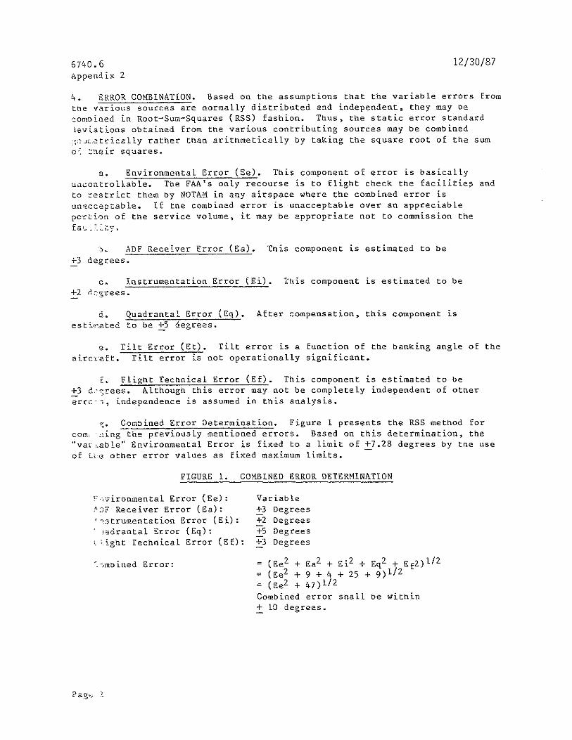