faac model 400 series (english) - faac gate · pdf filefor gate operators that utilize a...
TRANSCRIPT

400Hydraulic Swing Gate Operator
UL325 Compliant
FAAC International Inc.Headquarter & East Coast Operations5151 Sunbeam RoadSuites 9-11Jacksonville, FL 32257Tel. 866 925 3222www.faacusa.com
FAAC International Inc.West Coast Operations
357 South Acacia AvenueUnit 357
Fullerton, CA 92831Tel. 800 221 8278


1
CONTENTS
FAAC 400 Hydraulic Swing Gate Operator
IMPORTANT SAFETY INFORMATION 4
Important Safety Instructions 4Important Installation Instructions 4General Safety Precautions 5UL325 Gate Operator Classifications 6Installing the Warning Signs 6
1. TECHNICAL SPECIFICATIONS 7
Dimensions 7
2. WIRING 7
3. INSTALLING THE MODEL 400 8
3.1. Preliminary Checks 83.2. Installation Dimensions 83.3 General Rules for Determining Installation Dimensions 83.4. Installing the Operator 8
4. START-UP 10
Anti-Crushing System Adjustments 10
5. FINAL OPERATIONS 10
6. SYSTEM TEST 11
7. MANUAL OPERATION 11
8. RESTORING NORMAL OPERATING MODE 11
9. SPECIAL APPLICATIONS FOR SWING LEAF GATES 11
Opening Outward, with Operator Installed Inside 11
10. POSITIVE STOP ACCESSORY 12
11. MAINTENANCE AND REPAIRS 13
12. EXPLODED VIEWS 14
400 CBAC 14Cylinder 15Locking Cap 16Rear Flange 17
13. 455 D CONTROL BOARD 18
13.1 455 D Control Board Warnings 1813.2. Technical Specifications 1813.3 Electric Connections 1813.4. 455 D Layout and Components 1813.5 Programming 2213.6 Start-Up 2413.7 System Test 25
14. OPERATING MODES DETAILED DESCRIPTION 26
15. PREWIRED ENCLOSURE DIAGRAM 28

2FAAC 400 Hydraulic Swing Gate Operator
16. POWER AND ACCESSORIES CONNECTIONS 29
AC Power Wiring Guidelines 29AC Power Connection 29Magnetic Lock Connection 29
17. TROUBLESHOOTING 30
LIMITED WARRANTY 31
Read this instruction manual before you begin installing the product.
= Information regarding personal safety and proper maintanence of the product.
= Information regarding the product’s characteristics or operation.

3FAAC 400 Hydraulic Swing Gate Operator
1. Install the gate operator only when the following condi-tions have been met:
• The operator is appropriate for the type and usage class of the gate.
• All openings of a horizontal slide gate have been guarded or screened from the bottom of the gate to a minimum of 4 feet (1.25 m) above the ground to prevent a 2.25 inch (55 mm) diameter sphere from passing through openings anywhere in the gate or through that portion of the adjacent fence that the gate covers when in the open position.
• All exposed pinch points are eliminated or guarded.
• Guarding is supplied for exposed rollers.
2. The operator is intended for installation on gates used by vehicles only. Pedestrians must be provided with a sepa-rate access opening.
3. To reduce the risk of entrapment when opening and closing, the gate must be installed in a location that allows adequate clearance between the gate and adjacent struc-tures. Swinging gates shall not open outward into public access areas.
4. Before installing the gate operator, ensure that the gate has been properly installed and that it swings freely in both directions. Do not over-tighten the operator clutch or pressure relief valve to compensate for a damaged gate.
5. User controls must be installed at least 6 feet (1.83 m) away from any moving part of the gate and located where the user is prevented from reaching over, under, around or through the gate to operate the controls. Controls located outdoors or those that are easily accessible shall have security features to prevent unauthorized use.
6. The Stop and/or Reset buttons must be located within line-of-sight of the gate. Activation of the reset control shall not cause the operator to start.
7. All warning signs and placards must be installed and easily seen within visible proximity of the gate. A minimum of one warning sign shall be installed on each side of the gate.
8. For gate operators that utilize a non-contact sensor (photo beam or the like):
• See instructions on the placement of non-contact sensors for each type of application.
• Exercise care to reduce the risk of nuisance tripping, such as when a vehicle trips the sensor while the gate is still moving.
• Locate one or more non-contact sensors where the risk of entrapment or obstruction exists, such as at the reachable perimeter of a moving gate or barrier.
• Use only FAAC “Photobeam” photoelectric eyes to comply with UL325.
9. For gate operators that utilize a contact sensor (edge sensor or similar):
Important Installation Instructions
WARNING: TO REDUCE THE RISK OF SEVERE INJURY OR DEATH:
• READ AND FOLLOW ALL INSTRUCTIONS.
• Never let children operate or play with the gate controls. Keep remote controls away from children.
• Always keep people and objects away from the gate. NO ONE SHOULD CROSS THE PATH OF A MOVING GATE.
• Test the gate operator monthly. The gate MUST reverse on contact with a rigid object or when an object activates a non-contact sensor. If necessary, adjust the force or the limit of travel and then retest the gate operator. Failure to properly adjust and retest the gate operator can increase the risk of injury or death.
• Use the manual release mechanism only when the gate is not moving.
• KEEP GATE PROPERLY MAINTAINED. Have a qualified service person make repairs to gate hardware.
• The entrance is for vehicles only. Pedestrians must use a separate entrance.
• SAVE THESE INSTRUCTIONS.
IMPORTANT SAFETY INFORMATION
Important Safety Instructions

4FAAC 400 Hydraulic Swing Gate Operator
Gate Construction
Vehicular gates should be constructed and installed in accordance with ASTM F2200: Standard Specification for Automated Vehicular Gate Construction.
For more information, contact ASTM at: www.astm.org
Installation
• If you have any questions or concerns regarding the safety of the gate operating system, do not install the operator and consult the manufacturer.
• The condition of the gate structure itself directly affects the reliability and safety of the gate operator.
• Only qualified personnel should install this equipment. Failure to meet this requirement could cause severe injury and/or death, for which the manufacturer cannot be held responsible.
• The installer must provide a main power switch that meets all applicable safety regulations.
• It is extremely unsafe to compensate for a damaged gate by increasing hydraulic pressure.
• Install devices such as reversing edges and photo beams to provide better protection for personal property and pedestrians. Install reversing devices that are appropriate to the gate design and application.
• Before applying electrical power, ensure that voltage requirements of the equipment correspond to the supply voltage. Refer to the label on your gate operator system.
Usage
• Use this equipment only in the capacity for which it was designed. Any use other than that stated should be considered improper and therefore dangerous.
• The manufacturer cannot be held responsible for damage caused by improper, erroneous or unreasonable use.
• If a gate system component malfunctions, disconnect the main power before attempting to repair it.
• Do not impede the movement of the gate, you may injure yourself or damage the gate system as a result.
• This equipment may reach high thermal temperatures during normal operation, therefore use caution when touching the external housing of the gate operator.
• Use the manual release mechanism according to the procedures presented in this manual.
• Before performing any cleaning or maintenance operations, disconnect power to the equipment.
• All cleaning, maintenance or repair work must performed by qualified personnel.
General Safety Precautions
• Locate one or more contact sensors where the risk of entrapment or obstruction exists, such as at the leading edge, trailing edge, and post mounted both inside and outside of a vehicular horizontal slide gate
• Locate one or more contact sensors at the bottom edge of a vehicular vertical lift gate.
• Locate one or more contact sensors at the bottom edge of a vertical barrier (arm).
• Locate one or more contact sensors at the pinch point of a vehicular vertical pivot gate.
• Locate hard-wired contact sensors and wiring so that communication between sensor and gate operator is not subjected to mechanical damage.
• Locate wireless contact sensors, such as those that transmit radio frequency (RF) signals, where the transmission of signals are not obstructed or impeded by building structures, natural landscaping or similar hindrances. Wireless contact sensors shall function under their intended end-use conditions.
• Use only FAAC MSE MO, CN60 or M60 edge sensors.
Important Installation Instructions (continued)

5FAAC 400 Hydraulic Swing Gate Operator
RESIDENTIAL VEHICULAR GATE OPERATOR CLASS I
A vehicular gate operator system intended for use in a single family dwelling, garage or associated parking area.
UL325 Gate Operator Classifications
COMMERCIAL / GENERAL ACCESS VEHICULAR GATE OPERATOR CLASS II
A vehicular gate operator system intended for use in commercial locations or buildings such as multi-family housing units (five or more single family units), hotels, parking garages, retail stores or other buildings that service the general public.
INDUSTRIAL / LIMITED ACCESS VEHICULAR GATE OPERATOR CLASS III
A vehicular gate operator system intended for use in industrial locations or buildings such as factories, loading docks or other locations not intended to service the general public.
RESTRICTED ACCESS VEHICULAR GATE OPERATOR CLASS IV
A vehicular gate operator system intended for use in guarded industrial locations or buildings such as airport security areas or other restricted access locations that do not service the general public, and in which unauthorized access is prevented via supervision by security personnel.
This FAAC swing gate operator is supplied with two warning signs to alert people that a possible hazard exists and that appropriate actions should be taken to avoid the hazard or to reduce exposure to it.
Permanently install one warning sign on each side of the gate so they are fully visible to traffic and pedestrians.
Use appropriate hardware such as metal screws (not supplied) to permanently install each warning sign.
Installing the Warning Signs

6
15 AWG
20 AWG
15 AWG
15 A
WG
20 A
WG
20 A
WG
15 AWG
20 AWG
FAAC 400 Hydraulic Swing Gate Operator
3 11/32”
3 11/32”
4 3/4”
MODEL CBC CBAC SB SBS CBACR CBAC EG SB EG
Max Traction / Thrust Force: (daN) 620 620 620 775 465 465 465
Effective Rod Stroke: (inches) 10 1/4 10 1/4 10 1/4 10 1/4 10 1/4 15 15
Linear Rod Speed: (inches/sec) 0.4 0.4 0.4 0.3 0.6 0.6 0.6
Operator Weight: (lbs) 19 19 19 19 19 22 22Use Frequency: (cycles/hour) 70 70 70 60 80 50 50
Pump Flow-Rate: (liters/min) 1 1 1 0.75 1.5 1.5 1.5
Hydraulic Locking:(1) = Closing (2) = Opening and Closing
(1) (2) / / (2) (2) /
Max Leaf Length: (feet) 16 16 18 20 12 18 20Power Supply 115 VAC ± 10% or 230 VAC +6% -10% 50/60 Hz.Absorbed Power (W) 220Absorbed Current (A) 1 (230V) or 2 (115V)Electric Motor (rpm) 1400 - 4 polesThermal Protection on Winding (°F) 248°
Thrust Capacitor 25uF / 115 V or 8uF / 230 VAmbient Operating Temperature Range (°F) - 4° to 131°
Protection Class IP55
MODEL 400 OPERATORThese instructions apply to the following models:400 CBC, 400 CBAC, 400 SB, 400 SBS, 400 CBACR, 400 CBAC EG, 400 SB EG.The FAAC Model 400 Swing Gate Operator consists of an electric pump and a hydraulic piston which transmits drive to the gate leaf.
Models with hydraulic locking do not require the installation of electric locks, as they provide mechanical locking of the leaf when the motor is not operating.
Models without hydraulic locking require the installation of electric locks to ensure that the leaf is mechanically locked.
FAAC 400 Operators were designed and built to automate swing leaf gates. Do not use for any other purpose.
Dimensions
2. WIRING
Figure 3
1. Operators Mod 400
2. Photocells
3. Electronic control unit
4. Key operated push-button
5. Radio receiver
6. Flashing light
7. Electric lock (if necessary)
Table 1: 400 Operator – Technical Specifications
OPERATOR TYPE
STAN-DARD EG
A OVERALL DIMENSIONS 40 1/2 ” 50 1/2 ”
B DISTANCE BETWEEN ATTACHMENTS 27 1/2 ” 32 1/4 ”
C EFFECTIVE STROKE 10 1/4 ” 15”
1. TECHNICAL SPECIFICATIONS
• When laying electrical cables, use conduits with adequate rigidity and flexibility.
• Always separate low voltage wiring from AC power cables. Use separate sheaths to avoid electrical interference.
Figure 2
Figure 1

7
Lo
Standard = 37 3/4”, EG = 47 1/4”
Z min = 2”
S < 0
S = 0
S > 0
y Standard = 3”y EG= 4”
FAAC 400 Hydraulic Swing Gate Operator
If the dimensions indicated in table A or B cannot be achieved, the following must be considered in order to calculate different measurements:
• To obtain 90° opening of the leaf: a + b = c.• To obtain over 90° opening of the leaf: a + b < c.• Lower a and b dimensions will result in higher speeds. • Limit the difference between a and b to within 1.5 inches.
Higher differences will considerably vary gate opening and closing speed.
• The minimum Z dimension is 2 inches (Fig. 4);• If the pillar dimensions or the position of the hinge
(dimension d) do not make it possible to keep dimension a at the required size, a niche must be made in the pillar as shown in Fig. 5.
• Dimension a must always be larger than dimension E.For installations that open outward, refer to Section 9.1.
Figure 4
3. INSTALLING THE MODEL 400
3.2. Installation Dimensions
To ensure a correctly operating automated system, the struc-ture of the gate must satisfy the following requirements:
• Leaf length should not exceed “Max Leaf Length” dimensions in Table 1.
• Gate should have a strong and rigid leaf structure.• Gate leaves should have a smooth, uniform movement du-
ring the entire length of travel without any irregular friction. • Existing hinges should be in good condition.• Travel limit mechanical stops must be provided.• Perform all metal work before installing the automated gate
operator system.• The condition of the structure directly influences the reliability
and safety of the automated system.
Attention: To avoid compromising operator functionality, use measurements and dimensions indicated.
1.) Fasten the rear attachment to a pillar or column support. Follow the measurements indicated in Tables A / B. If necessary, modify the length of the supplied attachment.
• For iron pillars, weld the rear attachment (Fig. 6, Ref. 2) directly to the pillars.
• For masonry pillars, select one of the following solutions:
A.) Install an appropriate wall plate and then accurately weld the rear attachment.
OR
B.) Use screws and expansion plugs to secure the rear attachment plate (Fig. 6, Ref. a) to the pillar. Then weld the rear attachment to the plate as shown in Figure 6.
Table B: Recommended Dimensions for EG Operators
(*) Rod effective stroke (**) maximum dimension
Opening Angle a b c(*) d(**) s90° 7 7/8 6 1/4 15 5 7/8 3/4
115° 6 3/4 6 1/4 15 4 3/8 3/4
125° 5 1/8 6 3/4 15 3 1/8 3/4
Opening Angle a b c(*) d(**) s90° 5 1/16 5 1/16 10 1/4 3 1/8 3/4
115° 4 4 3/4 10 1/4 2 3/4
125° 3 1/2 4 3/4 10 1/4 1 1/2 0
Table A: Recommended Dimensions for Standard Operators
(*) Rod effective stroke (**) maximum dimension
c = In order to prevent the rod from reaching its stop point internally when opening and closing, the effective rod stroke is shorter than the maximum stroke.
3.1. Preliminary Checks
- in inches
3.3 General Rules for Determining Installation Dimensions
3.4. Installing the Operator
- in inches
Figure 5

8
Figure 6
Figure 7
1/4 Inch
FAAC 400 Hydraulic Swing Gate Operator
Figure 8
Figure 9
Figure 10
2.) Secure the operator to the rear attachment with the supplied screws (Fig. 6).
3.) Screw, halfway down, the front attachment onto the rod (Fig. 8, Ref.1). Tighten with the supplied nut.
4.) Release the operator (see Section 7).
5.) Fully extend the rod out to its stopping point, then push it back approximately 1/4 inch (Fig. 7).
6.) Relock the operator (see Section 8).
7.) Fit the front bracket onto the rod (Fig. 8, Ref. 2)
8.) Close the gate leaf and, while keeping the operator perfectly horizontal, identify and mark the location of the front bracket on the leaf (Fig. 9).
9.) Temporarily fasten the front bracket to the leaf with two weld spots (protect rod from welding slag).
If the gate structure does not permit the bracket to be firmly fastened, modify the structure to create a solid support base.
10.). Release the operator and manually check that the gate can freely and completely open. Ensure that it stops via the travel limit mechanical stops and that leaf movement is good and frictionless.
11.) Temporarily release the operator from the bracket and then permanently weld the bracket to the leaf. Prevent welding slag from damaging the rod. (Fig.10). If welding is not feasible, secure the front and rear attachment plates with screws.
12.) Grease all securing pins of the attachments.
13.) Prepare the protective housing and fit it on the operator as shown in Fig. 11. Fit the electric cable strain relief (Fig. 12, Ref. 3).
14.) Re-lock the operator and make electrical connections to the electronic control unit following the instructions in Chapter 13.
9FAAC 400 Hydraulic Swing Gate Operator
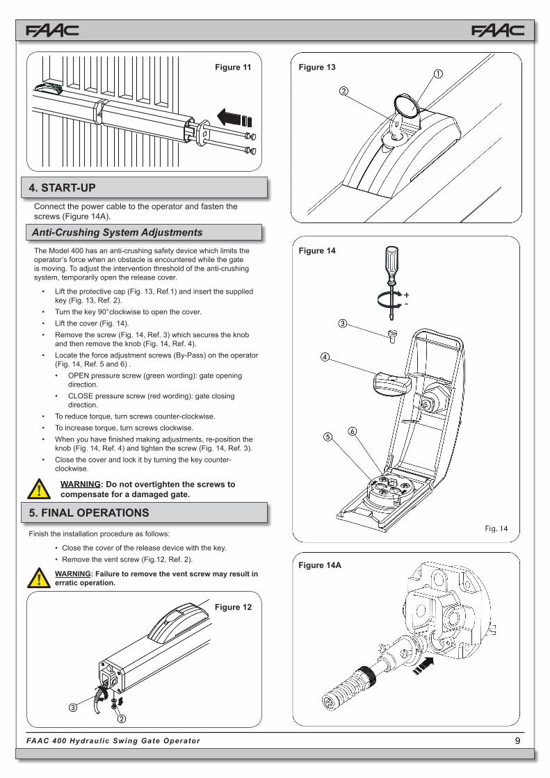
4. START-UP
The Model 400 has an anti-crushing safety device which limits the operator’s force when an obstacle is encountered while the gate is moving. To adjust the intervention threshold of the anti-crushing system, temporarily open the release cover.
• Lift the protective cap (Fig. 13, Ref.1) and insert the supplied key (Fig. 13, Ref. 2).
• Turn the key 90°clockwise to open the cover.• Lift the cover (Fig. 14).• Remove the screw (Fig. 14, Ref. 3) which secures the knob
and then remove the knob (Fig. 14, Ref. 4).• Locate the force adjustment screws (By-Pass) on the operator
(Fig. 14, Ref. 5 and 6) .• OPEN pressure screw (green wording): gate opening
direction.• CLOSE pressure screw (red wording): gate closing
direction.• To reduce torque, turn screws counter-clockwise.• To increase torque, turn screws clockwise.• When you have finished making adjustments, re-position the
knob (Fig. 14, Ref. 4) and tighten the screw (Fig. 14, Ref. 3).• Close the cover and lock it by turning the key counter-
clockwise.
Figure 11 Figure 13
Figure 12
Connect the power cable to the operator and fasten the screws (Figure 14A).
5. FINAL OPERATIONS
Finish the installation procedure as follows:
• Close the cover of the release device with the key.• Remove the vent screw (Fig.12, Ref. 2).
Figure 14
Figure 14A
Anti-Crushing System Adjustments
WARNING: Do not overtighten the screws to compensate for a damaged gate.
WARNING: Failure to remove the vent screw may result in erratic operation.

10FAAC 400 Hydraulic Swing Gate Operator
Opening Angle
a(inches)
b(inches)
s(inches)
d(**)(inches)
c(*)(inches)
90° 4 3 1/2 0 2 7 1/2
90° 4 5/16 4 0 2 3/8 8 1/4
90° 4 3/4 4 5/16 0 2 3/4 990° 5 1/8 4 3/4 0 3 1/8 9 7/8
Refer to Table 1 for this particular application. Select the operator according to leaf length as detailed in Table 1. Installation dimensions are provided in Table C.
To adjust the anti-crushing system for outward opening gates only, perform the following steps (note that these steps differ somewhat from instructions provided in Section 4.1):
• OPEN screw (green wording): gate closing direction.
• CLOSE screw (red wording): gate opening direction.
• To reduce torque, turn screws counter-clockwise.
• To increase torque, turn screws clockwise.
When you have finished installing the unit, run a functional check of the automated system and all ac-cessories connected to it, especially safety devices. Explain to the client the correct operation and use of the operator and indicate potentially dangerous areas of the automated system.
(*) Rod effective stroke (**) maximum dimension
Figure 17
Table C: Standard Operators Recommended Dimensions
If the gate has to be moved manually due to a power failure or a fault in the system, use the release device as described below.
• Lift the protective plug (Fig. 16, Ref. 1) and insert the supplied key (Fig. 16, Ref. 2).
• Turn the key 90°clockwise to open the cover.• Lift the cover (Fig. 16, Ref.3).• Turn the release knob counter-clockwise approxi-
mately two complete turns (Fig. 16, Ref. 4).You can now open or close the leaf manually.
7. MANUAL OPERATION
8. RESTORING NORMAL OPERATING MODE
To prevent an involuntary pulse from activating the operator during manual operation, cut power to the system before re-locking the operator.
• To re-lock the operator, turn the release knob clockwise until it stops (Fig. 16, Ref. 4).
• Close the cover and turn the key 90° counter-clockwise (Fig. 16, Ref. 2).
• Finally, remove the key and close the protective plug (Fig. 16, Ref. 1).
9. SPECIAL APPLICATIONS FOR SWING LEAF GATES
Opening Outward, with Operator Installed Inside
6. SYSTEM TEST
Figure 16

11FAAC 400 Hydraulic Swing Gate Operator
10. POSITIVE STOP ACCESSORY
In case the gate doesn’t allow you to have built in mechanical stops, it is possible to install, directly on the operator, an accessory to limit the rod’s travel in both directions.
(P/N: 490109 STANDARD, 490043 EG)
The accessory is mounted on the front flange of the operator using the supplied bolts.
With the use of the proper square shaped swivel joint (supplied):
It’s possible to limit the rod’s travel and create two solid mechanical stop positions.
For additional details please refer to the instructions included with the positive stop accessory.

12FAAC 400 Hydraulic Swing Gate Operator
Run a functional check of the system at least twice a year. Pay special attention to the efficiency of safety and release devices (Including the thrust force of the operator), and the perfect operation of the gate hinges.
Checking Oil Level:
Periodically check the oil level inside the tank.
• Cut power to the system.
• Position the operator vertically, with the rear flange high up.
• Remove the oil fill plug.
• Insert a screwdriver until it comes in contact with the electric motor as shown in Fig. 18.
• Remove the screwdriver and check oil level as shown in Fig. 18.
• USE ONLY FAAC HP FLUID OIL
Periodically check for correct adjustment of the anti-crushing safety device and the effectiveness of the release system to allow manual operation.
Safety devices installed on the system must be checked every 6 months.
For repairs, contact FAAC’s authorized repair centers.
Figure 1811. MAINTENANCE AND REPAIRS

13FAAC 400 Hydraulic Swing Gate Operator
400 CBAC
POS. P/N DESCRIPTION
01 702202 GALVANIZED NUT (8 MM)
02 7220015 REAR MOUNTING BRACKET
03 7284005 REAR MOUNTING PLATE
04 7182075 SHORT PIN
05 7228015 DIE-CAST REAR FORK
06 702302 SELF-LOCKING NUT
08 70991015 GASKET DIAMETER 80
09 490325 KIT LOCKING CAP
10 701803 M4X10 SELF TAPPING SCREW
11 7119475 VIBRATION DAMPENER
12 701006 4X45 BOLT
13 703101 LOCK WASHER (4 MM)
14 702003 HEX NUT (4 MM)
15* 7700205 MOTOR 220V 4P.
16 7119485 VIBRATION DAMPENER
17 7161825 400 OPERATOR TANK
18 7320065 VENT SCREW LABEL
19 7182175 LONG PIN
20 701829 TORX M5X20 INOX SCREW
21 7110015 OIL PLUG
POS. P/N DESCRIPTION
22 701039 VENT SCREW 4X6
23 7094065 SOFT COPPER WASHER
29 3204425 CAST-IRON PUMP LT.1
30 706152 PIN 4x28 m6
31 7090010015 GASKET OR 4.48X1.78
32 7039025 OPERATOR FRONT WASHER
33 702201 HEX. NUT
34 7073095 SWIVEL JOINT SQUARE
35 7220355 FRONT MOUNTING BRACKET
36 703401 LOCK WASHER 4.3X9
37 7119405 PLUG FOR COVER
38 7019195 TIE ROD FOR COVER
39 4170015 END CAP FOR COVER
40 7272105 PROTECTIVE COVER
41 3900985 SKINPACK 400
42 2167+ SEAL KIT 400
43 714017 FAAC HP OIL LT.1
44** 2707 8 μF CAPACITOR
45 7228015+ SWING GATE OPERATOR ALUMINIUM FORK KIT
12. EXPLODED VIEWS
* P/N for 115V Motor: 77000423
** P/N for 115V Motor Capacitors: 2705

14FAAC 400 Hydraulic Swing Gate Operator
Cylinder
POS. P/N DESCRIPTION
01 7049135 RETAINING RING NUT
02 7090050015 GASKET O-RING 10.82X1.78
03 4404065 INLET VALVE WITH SPRING
04 7049005 RETAINER
05 4404085 LOCK VALVE IN ZAMACK
06 4994655 VALVE BODY
07 7230295 TIE ROD CYLINDER
08 703204 STAR WASHER
09 7090300015 GASKET O-RING 7.66X1.78
10 4180285 SHUTTLE PISTON WITH O-RING
11 7366025 CYLINDER
12 7091015 SEAL (PISTON)
13 4350105 PISTON ASSEMBLY
14 4994625 FRONT FLANGE
POS. P/N DESCRIPTION
15 701829 TORX M5X20 INOX SCREW
16 63000315 FRONT FLANGE BUSHING
17 7090360025 GASKET O-RING 40.95X2.62
18 7090815 D-RING
19 7094505 GUIDE RING
20 7361335 RETRACT TUBE
21 7310315 BY-PASS ASSEMBLY
22 7210025 BY-PASS ASSEMBLY
23 711021 BY-PASS ASSEMBLY
24 7090280015 GASKET O-RING 5.28X1.78
25 7043055 SPACER
26 4180195 MANUAL RELEASE
27 4180415 KIT BY PASS ASSEMBLY
28 4404095 BIDIRECTIONAL INLET VALVE
15FAAC 400 Hydraulic Swing Gate Operator
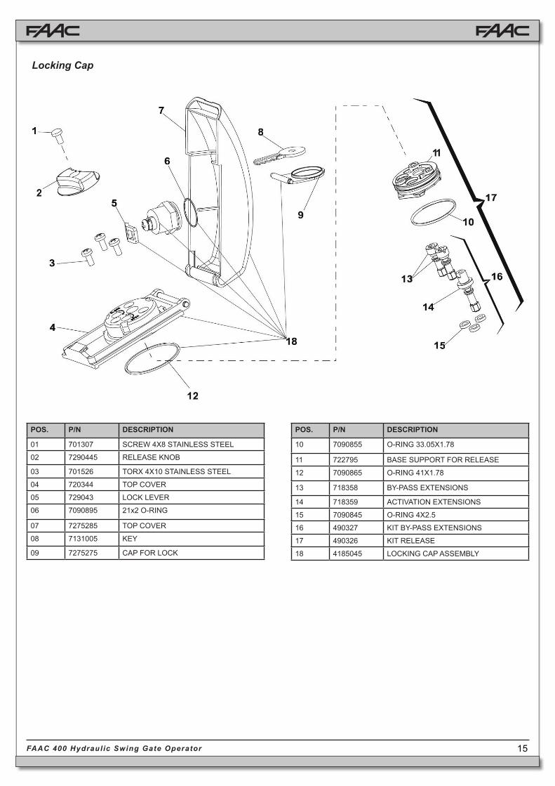
Locking Cap
POS. P/N DESCRIPTION
01 701307 SCREW 4X8 STAINLESS STEEL
02 7290445 RELEASE KNOB
03 701526 TORX 4X10 STAINLESS STEEL
04 720344 TOP COVER
05 729043 LOCK LEVER
06 7090895 21x2 O-RING
07 7275285 TOP COVER
08 7131005 KEY
09 7275275 CAP FOR LOCK
POS. P/N DESCRIPTION
10 7090855 O-RING 33.05X1.78
11 722795 BASE SUPPORT FOR RELEASE
12 7090865 O-RING 41X1.78
13 718358 BY-PASS EXTENSIONS
14 718359 ACTIVATION EXTENSIONS
15 7090845 O-RING 4X2.5
16 490327 KIT BY-PASS EXTENSIONS
17 490326 KIT RELEASE
18 4185045 LOCKING CAP ASSEMBLY
16FAAC 400 Hydraulic Swing Gate Operator
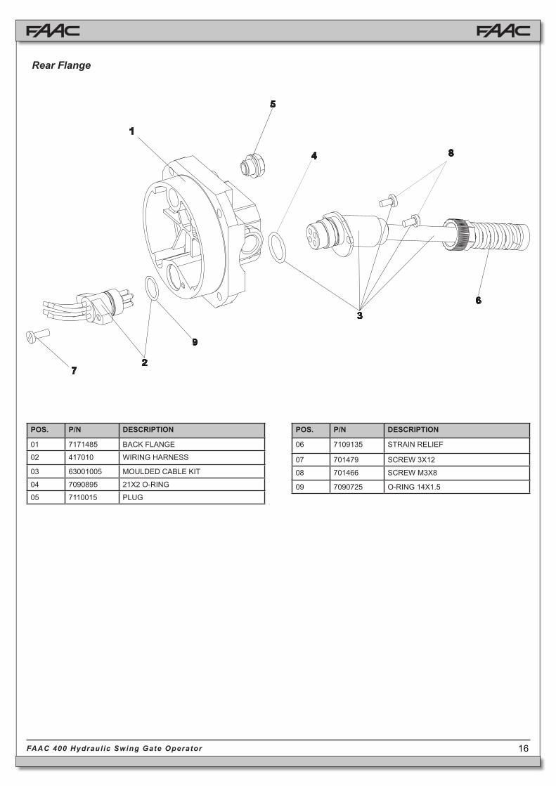
POS. P/N DESCRIPTION
01 7171485 BACK FLANGE
02 417010 WIRING HARNESS
03 63001005 MOULDED CABLE KIT
04 7090895 21X2 O-RING
05 7110015 PLUG
POS. P/N DESCRIPTION
06 7109135 STRAIN RELIEF
07 701479 SCREW 3X12
08 701466 SCREW M3X8
09 7090725 O-RING 14X1.5
Rear Flange

17FAAC 400 Hydraulic Swing Gate Operator
Figure B
13.4. 455 D Layout and Components
NB: Capacitors are supplied with the operator.
Important: Before attempting any work on the control board (connections, maintenance), always turn off power.
13. 455 D CONTROL BOARD
13.3 Electric Connections
J4 J1J3
F1
F2
PE N LMAIN
1 2 4 5 6 7 8COM OP
M1 COM OPM2 CL LAMP
9 10 11 12 13 14 15 16 17 18 19
OPENA B STP CL OP
FSW - - - +24V+ + -TX
FSW
20 21
W.L.LOCK
J5
J2
F
22 23 24 25
FC
A1
FC
C1
FC
A2
FC
C2
–+
STOP
OP_A
OP_B
FSWCL
FSWOP
FCC1
FCC2
FCA1
FCA2
J6
Figure A
F
F1
F2
J1
J2
J3 J4J5
J6
DL
–+
Power Supply 115 V~ ± 10% or 230 V~ +6% -10% 50/60 HzAbsorbed Power 10 WMotor Max. Load 800 WAccessories Max. Load 0,5 AElectric Lock Max. Load 15 VAAmbient Operating Temperature Range -4°F to +131°FProtection Fuses 2 (see Fig. A)Function Logics: Semi-automatic / Automatic / Safety Devices / “Stepped” Semi-automatic / “Stepped” Automatic / “Stepped” Safety Devices / Semi-automatic B / Dead-man COpening/Closing Time Programmable (from 0 to 120 s)Pause Time Programmable (from 0 to 4 min.)Closing Leaf Delay Programmable (from 0 to 4 min.)Opening Leaf Delay 2 s (can be excluded)Thrust Force: Adjustable on 50 levels for each motorTerminal Board Inputs: Open / Open Free Leaf / Stop / Limit-switch Opening Safety Devices / Closing Safety Devices / Power Supply + Earth.Terminal Board Outputs: Flashing Lamp / Motors / 24 VDC Acces-sories Power Supply / 24 VDC Indicator-Light / Fail Safe / 12 VAC Electric Lock Power SupplyProgrammable Functions: Logic / Pause Time / Thrust Force / Torque at Initial Thrust / Opening and Closing Leaf Delay / Reversing Stroke / Over-Pushing Stroke / Indicator-Light / Pre-Flashing / Electric Lock / Fail Safe / Safety Devices Logic / Assistance Request / Detection Time of Obstacle or Contact PointLearning Function: Simple or complete work time learning, with or without Limit-switch and/or Gatecoder.
13.2. Technical Specifications
13.1 455 D Control Board Warnings
Please refer to Chapter 16 for AC power wiring guidelines
DL SIGNALLING AND PROGRAMMING DISPLAY
J1 LOW VOLTAGE TERMINAL BLOCK
J2 CONNECTOR FOR RP RECEIVER
J3 AC POWER SUPPLY TERMINAL BLOCK
J4 MOTORS AND FLASHING LAMP CONNECTION TERMINAL BLOCK
J5 INDICATOR-LIGHT AND ELECTRIC LOCK TERMINAL BLOCK
J6 LIMIT-SWITCH AND GATECODER TERMINAL BLOCK
F1 MOTORS AND TRANSFORMER PRIMARY WINDING FUSE (F 5A - 230V) (F 10A - 115V)
F2 LOW VOLTAGE AND ACCESSORIES FUSE (T 800mA)
F “F” PROGRAMMING PUSH-BUTTON
– “–” PROGRAMMING PUSH-BUTTON
+ “+” PROGRAMMING PUSH-BUTTON
24 V DC3W
12 V AC
FCC
2
LIMIT-SWITCHOR GATECODER
230 VAC50 Hz
or115 VAC
60 Hz
VAC MAX.60W
OPEN A
OPEN B
STOP
BLU
E
BLU
E
For connection of the photo-cells and safety devices, see Section 13.4.1.
18FAAC 400 Hydraulic Swing Gate Operator
1
2
5
4
3
1
2
RX CL TX CL
1
2
5
4
3
1
2
RX OP/CLTX OP/CL
9 10 11 12 13 14 15 16 17 18 19
OPENA B STP CL OP
FSW - - - +24V+ + -TX
FSW
20 21
W.L.LOCK
-+
-+
-+
-+
1
2
5
4
3
1
2
RX OP TX OP
-+
-+
-+
-+
-+
+
+
+
-TX FSW
-TX FSW
-TX FSW
1
2
5
4
3
1
2
RX CL TX CL
1
2
5
4
3
1
2
RX OP/CLTX OP/CL
9 10 11 12 13 14 15 16 17 18 19
OPENA B STP CL OP
FSW - - - +24V+ + -TX
FSW
20 21
W.L.LOCK
-+
-+
-+
-+
-+
+-TX FSW
-+
+-TX FSW
9 10 11 12 13 14 15 16 17 18 19
OPENA B STP CL OP
FSW - - - +24V+ + -TX
FSW
20 21
W.L.LOCK
9 10 11 12 13 14 15 16 17 18 19
OPENA B STP CL OP
FSW - - - +24V+ + -TX
FSW
20 21
W.L.LOCK
Figure C
Figure F
Figure D Figure G
Figure E
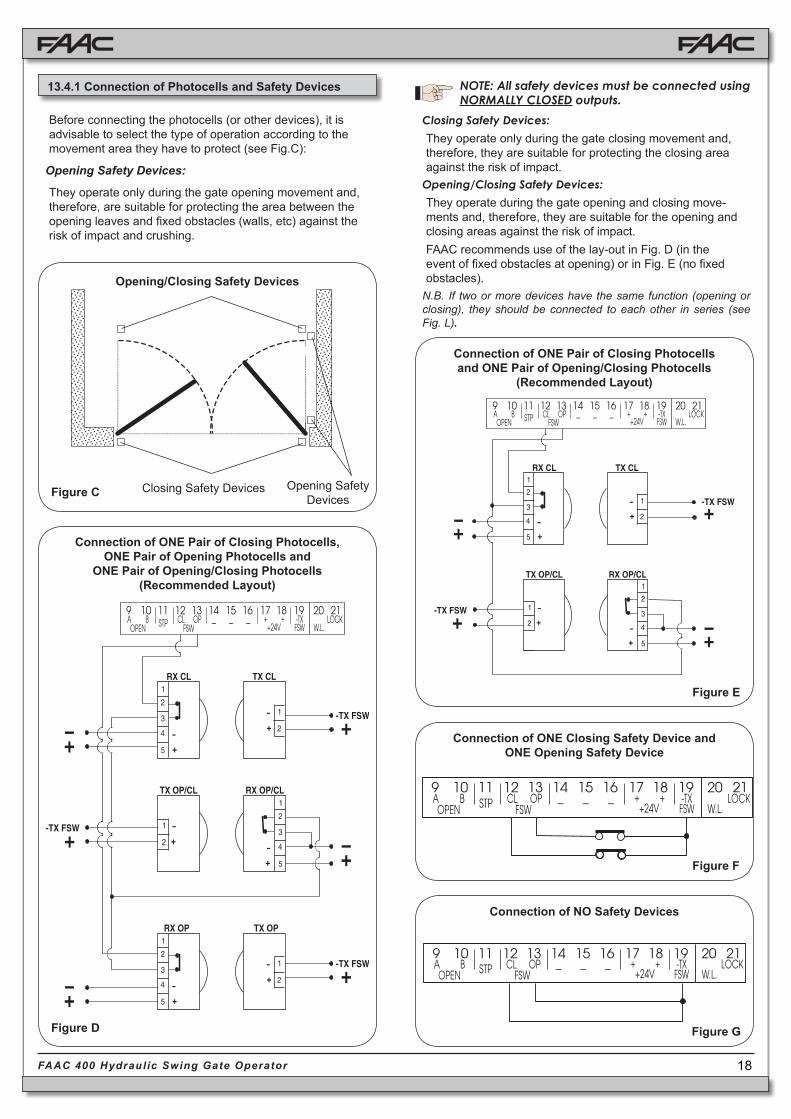
13.4.1 Connection of Photocells and Safety Devices
Before connecting the photocells (or other devices), it is advisable to select the type of operation according to the movement area they have to protect (see Fig.C):
Opening Safety Devices:
They operate only during the gate opening movement and, therefore, are suitable for protecting the area between the opening leaves and fixed obstacles (walls, etc) against the risk of impact and crushing.
Opening/Closing Safety Devices
Closing Safety Devices Opening Safety Devices
Connection of ONE Pair of Closing Photocells and ONE Pair of Opening/Closing Photocells
(Recommended Layout)
Closing Safety Devices: They operate only during the gate closing movement and, therefore, they are suitable for protecting the closing area against the risk of impact.
Opening/Closing Safety Devices: They operate during the gate opening and closing move-ments and, therefore, they are suitable for the opening and closing areas against the risk of impact.FAAC recommends use of the lay-out in Fig. D (in the event of fixed obstacles at opening) or in Fig. E (no fixed obstacles).
N.B. If two or more devices have the same function (opening or closing), they should be connected to each other in series (see Fig. L).
Connection of ONE Closing Safety Device and ONE Opening Safety Device
Connection of ONE Pair of Closing Photocells, ONE Pair of Opening Photocells and
ONE Pair of Opening/Closing Photocells (Recommended Layout)
Connection of NO Safety Devices
NOTE: All safety devices must be connected using NORMALLY CLOSED outputs.

19FAAC 400 Hydraulic Swing Gate Operator
-TX FSW
1
2
5
4
3
1
2
RX CL1 TX CL1
1
2
5
4
3
1
2
RX CL2TX CL2
9 10 11 12 13 14 15 16 17 18 19
OPENA B STP CL OP
FSW - - - +24V+ + -TX
FSW
20 21
W.L.LOCK
-+
-+
-+
-+
-+
+-TX FSW
-+
+
9 10 11 12 13 14 15 16 17 18 19
OPENA B STP CL OP
FSW - - - +24V+ + -TX
FSW
20 21
W.L.LOCK
1
2
5
4
3
1
2-+-
+
+-TX FSW
-+
RX OP TX OP
1
2
5
4
3
1
2
RX OP TX OP
1
2
5
4
3
1
2
RX CLTX CL
9 10 11 12 13 14 15 16 17 18 19
OPENA B STP CL OP
FSW - - - +24V+ + -TX
FSW
20 21
W.L.LOCK
-+
-+
-+
-+
-+
+-TX FSW
-+
+-TX FSW
9 10 11 12 13 14 15 16 17 18 19
OPENA B STP CL OP
FSW - - - +24V+ + -TX
FSW
20 21
W.L.LOCK
1
2
5
4
3
1
2
-+
-+
RX CL TX CL
+-TX FSW
-+
Figure H
Figure I
Figure J
Figure M
Figure L
Figure K
Connection of ONE Pair of Opening Photocells
Connection of ONE Pair of Opening Photocells and ONE Pair of Closing Photocells
Connection of TWO Pairs of Closing Photocells
Connection of ONE Pair of Closing Photocells
Connection of TWO N.C. Contacts in Series (e.g. Photocells, Stop)
Connection of TWO N.O. Contacts in Parallel (e.g. Open A, Open B)
13.4.2 Terminal Block J3 - Power Supply (Fig. B)
PE: Earth Connection / GroundN: AC V~ power supply (Neutral)L: AC V~ power supply (Line)NB: For correct operation, the board must be properly grounded.
13.4.3 Terminal Block J4 - Motors and Flashing Lamp
M1: COM / OP / CL: Connection to Motor 1Can be used in single-leaf configurationM2: COM / OP / CL: Connection to Motor 2Cannot be used in single-leaf configurationsLAMP: Flashing lamp output ( AC V ~)

20FAAC 400 Hydraulic Swing Gate Operator
455 D
RP 1418RP 433 RC
Figure Q
This is used for rapid connection to RP receivers (see Fig. Q). Connect the accessory with the components side facing the inside of the card. Insert and remove with power OFF.
13.4.4 Terminal Block J1 - Accessories (Fig. B)
OPEN A - “Total Opening” Command (N.O.): Any pulse generator (push-button, detector, etc.) which, by closing a contact, commands opening and/or closing of both gate leaves. To install several full opening pulse generators, connect the N.O. contacts in parallel.
OPEN B - “Partial Opening” Command (N.O.) / Closing: Any pulse generator (push-button, detector, etc.) which, by closing a contact, commands opening and/or closing of the leaf driven by motor M1. In the B and C logics, it always commands closing of both leaves. To install several partial opening pulse generators, connect the N.O. contacts in parallel.
STP - STOP Contact (N.C.): Any device (e.g. a push-button) which, by opening a contact, is able to stop gate movement. To install several STOP devices, connect the N.C. contacts in series.
NB: If STOP devices are not connected, jumper connect the STP terminals and -.
CL FSW - Closing Safety Devices Contact (N.C.): The purpose of the closing safety devices is to protect the leaf move-ment area during closing. During closing, in the E-A-S-EP-AP-SP logics, the safety devices reverse the movement of the gate leaves, or stop and reverse the movement when they are released (see Ad-vanced Programming in Section 13.5.2). During the closing cycle in logics B and C, they interrupt movement. They never operate during the opening cycle. If the closing safety devices operate when the gate is open, they prevent the leaf closing movement.
NB: If no closing safety devices are connected, jumper connect terminals CL and -TX FSW (Fig. G).
OP FSW - Opening safety devices contact (N.C.): The purpose of the opening safety devices is to protect the leaf move-ment area during opening. During opening, in the E-A-S-EP-AP-SP logics, the safety devices reverse the movement of the gate leaves. During the opening cycle in logics B and C, they interrupt movement. They never operate during the closing cycle.
If the opening safety devices operate when the gate is closed, they prevent the leaf opening movement.
NB: If no opening safety devices are connected, jumper connect inputs OP and -TX FSW (Fig. G).– - Negative for power supply to accessories
+ - 24 VDC - Positive for power supply to accessories
Important: Accessories max. load is 500 mA. To calculate current draw, refer to the instructions for individual accessories.
-TX FSW - Negative for power supply to photocell transmitters.
If you use this terminal for connecting the negative for supplying power to the photocell transmitters, you may, if necessary, also use the FAIL SAFE function (see Advanced Programming in Section 13.5.2).If this function is enabled, the equipment checks operation of the photocells before each opening or closing cycle.
13.4.5 Terminal Block J5 - Indicator-Light and Electric Lock
W.L. - Power supply to indicator-lightConnect a 24 VDC - 3 W max. indicator-light, if necessary, between this terminal and the +24V supply. To avoid compromising correct operation of the system, do not exceed the indicated power.LOCK - Power supply to electric lockIf necessary, connect a 12 VAC electric strike lock between this terminal and the +24V power supply. Please refer to Chapter 16 for Magnetic Lock connection.
13.4.6 Connector J2 - Rapid Connection to RP Receivers

21FAAC 400 Hydraulic Swing Gate Operator
= Semi-automatic= Automatic= “Safety” Automatic= “Stepped” Semi-automatic= “Stepped” Automatic= “Safety Stepped” Automatic= “B” Semi-automatic= Dead-man
FCC
2
RED
RED
BLACK
BLACK
WHITE
WHITE
LEAF 1 FORCE: Adjusts thrust of Motor 1.
= minimum force = maximum force (hydraulic)
press F
Figure S
The following table displays the sequence of functions accessible in BASIC PROGRAMMING:
BASIC PROGRAMMING
PAUSE TIME:This has effect only when automatic logic is selected.
Adjustable from to secs. in one-second
increments.
Subsequently, display changes to minutes and tenths
of seconds (separated by a decimal point), time
is adjusted in 10-second increments, up to
minutes max. Thus, if the unit displays , Pause
Time is 2 mins. and 50 secs.
Exit from programming and return to inputs status monitoring.
These inputs are designed for connection of opening and closing limit-switches or Gatecoders
The 400 operator cannot use limit switches but only Gatecoders. They are used to detect the leaf’s angular position and to thus obtain deceleration and stop positions more accurately than using the operating timing.
Please refer to Figure S for wiring information. If the Gatecoders are not used the J6 inputs can be left unconnected.
To program the 455D Control Board, you have to access “PRO-GRAMMING” mode. Programming is split into two parts: BASIC and ADVANCED.
LEAF 2 FORCE: Adjusts thrust of Motor 2.
= minimum force = maximum force (hydraulic)
LEAF 1 CLOSING DELAY:Delays closing start of leaf 1 with respect to leaf 2. Adjustable from to minutes (see Pause Time).
TIME LEARNING (see Section F.3.):Enables the selection between “simple” (automatic) learning and “complete” (manual choice of deceleration and stop points) learning.
+ ≈ 1 s. Simple Learning:
> 3 s. Complete Learning:
OPERATING LOGICS (see tab. 3/a - h):
If using hydraulic operators, set force to maximum level.
13.4.7 Terminal Block J6 - Limit-Switch or Gatecoder
13.5.1 Basic ProgrammingTo access BASIC PROGRAMMING, press key F:• Press and hold F, the unit will display the name of the first func-
tion / parameter.• When you release the key, the unit will display the parameter’s
current value.• Value can be modified with keys + and - . • Press and hold F again, the unit will display the name of the next
function / parameter.• When you reach the last function, press F to exit the program,
the display resumes monitoring input status.
Display Function Default
13.5 Programming
+
This is a brief description of the main operating logics of the system. For a complete description please refer to Table 3
• A (automatic): The gate opens on command and auto-matically closes after a pause phase. A second com-mand while opening is ignored; a second command dur-ing the pause phase interrupts the pause time; a second command during closing reopens the gate. A maintained open command will hold the gate open.
• S (security): The security mode is like A logic except that a second command during opening immediately closes the gate. A maintained open command will not hold the gate open.
• E (semi-automatic): This mode requires a second com-mand during opening stops the gate. A second command during closing reopens the gate.
• EP (semi-automatic, step by step): This mode requires a command to open and a command to close. A second command during opening or closing causes the gate to stop. A third command then reverses the previous motion of the gate.
• B (manned, pulsed): This mode is designed for guard station use and requires a three button switch (pulsed) to open, close, and stop the gate.
• C (manned and constant): This mode requires constant pressure switches. One to open and one to close. No pressure on a switch stops the gate.
13.4.8 Operating Logics

22FAAC 400 Hydraulic Swing Gate Operator
F ++
To access ADVANCED PROGRAMMING, press and hold key F and then press key +:• Release key +, the unit displays the name of the first function.• Release key F, modify the value of the function with keys
+ and -.• Press and hold key F, the unit displays the name of the next
function, and if you release it, the value that can be modified with keys + and -.
• When you reach the last function, press F to exit the program, the unit resumes monitoring input status.
The following table shows the sequence of functions accessible in ADVANCED PROGRAMMING:
ADVANCED PROGRAMMING
MAXIMUM TORQUE AT INITIAL THRUST:The motors operate at maximum torque (ignoring the torque setting) at start of movement. Useful for heavy leaves.
= Active = DisabledLAST STROKE AT CLOSING:The motors are activated at full speed for 1 second to facilitate locking of the electric lock.
= Active =Disabled
REVERSING STROKE:Before opening, while the gate is closed, the motors thrust to close for 2 seconds thus facilitating release of the electric lock.
= Active = DisabledLEAF 2 OPENING DELAY (2 s):Enables delayed start (at opening) of leaf 2, avoiding interference between leaves.
= Active = DisabledFAIL SAFE:If this function is activated, it enables a function test of the photocells before any gate movement. If the test fails (photocells not serviceable), the gate does not start the movement.
= Active = Disabled
PRE-FLASHING (5 s):Activates the flashing lamp for 5 seconds before start of movement.
= Active = Disabled
ELECTRIC LOCK ON LEAF 2:For using the electric lock on leaf 2 instead of on leaf 1.
= Active = Disabled
INDICATOR-LIGHT:
If is selected, the output functions as a standard indicator-light (lighted at opening and pause, flashing at closing, and off when gate is closed). Different figures correspond to the extra time compared to normal work time (opening or closing) when the output can be used - via a relay - to power a courtesy light. Time can be adjusted from to sec. in 1 sec. steps, and from
to min. in 10 sec. steps.
= Standard indicator-lightfrom to = Timed output
CLOSING PHOTOCELLS REVERSE AT RELEASE:Enable this function if you want the closing photocells to stop movement and reverse at release. Default setting is immediate reverse.
= Active = Disabled
ASSISTANCE REQUEST (combined with next function):If activated, at the end of countdown (settable with the next function i.e. “Cycle programming”) it affects 8 s of pre-flashing at every Open pulse (job request). Can be useful for setting scheduled maintenance jobs.
= Active = Disabled
CYCLE PROGRAMMING:For setting countdown of system operation cycles. Settable (in thousands) from to thousand cycles. The displayed value is updated as cycles proceed.This function can be used to check use of the board or to exploit the “Assistance request”.
A.D.M.A.P. FUNCTION:When enabled, the safety devices operate in compliance with French standard NFP 25/362.
= Active = Disabled
Exit from programming and return to inputs status monitoring.
NB: Parameter modifications take effect immediately. Exit out of programming to save changes. If the equipment is powered down before returning to normal status monitoring, any unsaved modifications will be lost.
To restore programming defaults, press and hold the three buttons +, -, F simultaneously for 5 seconds.
ANTI-CRUSHING SENSITIVITY:When operating with the gatecoder, it controls anti-crushing sensitivity.
= Low = High.EXTRA WORK TIME:
When operating without a gatecoder and limit-switch, if reversing occurs, and if the leaf does not reach its end contact point, you can activate this function to increase work time.
= Active = Disabled
Display Function Default13.5.2 Advanced Programming
Display Function Default
23FAAC 400 Hydraulic Swing Gate Operator
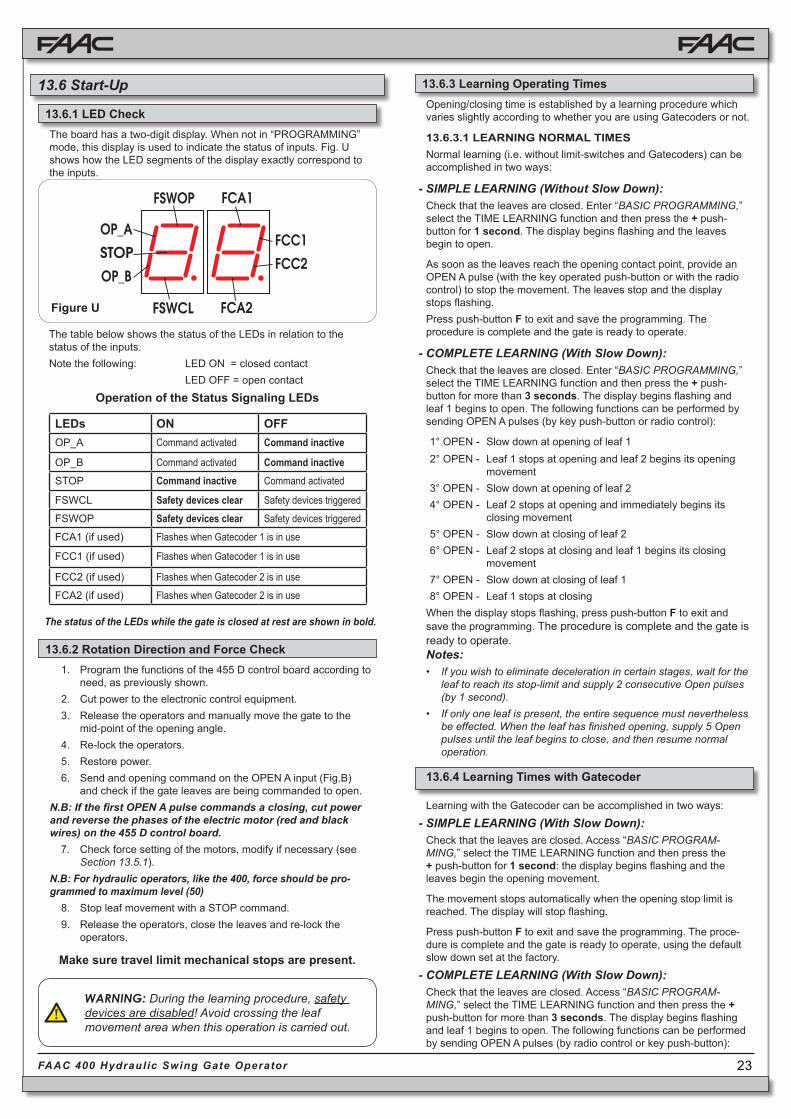
Figure U
The board has a two-digit display. When not in “PROGRAMMING” mode, this display is used to indicate the status of inputs. Fig. U shows how the LED segments of the display exactly correspond to the inputs.
The table below shows the status of the LEDs in relation to the status of the inputs.Note the following: LED ON = closed contact
LED OFF = open contact
Operation of the Status Signaling LEDs
The status of the LEDs while the gate is closed at rest are shown in bold.
1. Program the functions of the 455 D control board according to need, as previously shown.
2. Cut power to the electronic control equipment.3. Release the operators and manually move the gate to the
mid-point of the opening angle.4. Re-lock the operators.5. Restore power.6. Send and opening command on the OPEN A input (Fig.B)
and check if the gate leaves are being commanded to open.N.B: If the first OPEN A pulse commands a closing, cut power and reverse the phases of the electric motor (red and black wires) on the 455 D control board.
7. Check force setting of the motors, modify if necessary (see Section 13.5.1).
N.B: For hydraulic operators, like the 400, force should be pro-grammed to maximum level (50)
8. Stop leaf movement with a STOP command.9. Release the operators, close the leaves and re-lock the
operators.
Opening/closing time is established by a learning procedure which varies slightly according to whether you are using Gatecoders or not.
13.6.3.1 LEARNING NORMAL TIMESNormal learning (i.e. without limit-switches and Gatecoders) can be accomplished in two ways:
- SIMPLE LEARNING (Without Slow Down):Check that the leaves are closed. Enter “BASIC PROGRAMMING,” select the TIME LEARNING function and then press the + push-button for 1 second. The display begins flashing and the leaves begin to open.
As soon as the leaves reach the opening contact point, provide an OPEN A pulse (with the key operated push-button or with the radio control) to stop the movement. The leaves stop and the display stops flashing.Press push-button F to exit and save the programming. The procedure is complete and the gate is ready to operate.
- COMPLETE LEARNING (With Slow Down):Check that the leaves are closed. Enter “BASIC PROGRAMMING,” select the TIME LEARNING function and then press the + push-button for more than 3 seconds. The display begins flashing and leaf 1 begins to open. The following functions can be performed by sending OPEN A pulses (by key push-button or radio control):
1° OPEN - Slow down at opening of leaf 12° OPEN - Leaf 1 stops at opening and leaf 2 begins its opening
movement 3° OPEN - Slow down at opening of leaf 24° OPEN - Leaf 2 stops at opening and immediately begins its
closing movement5° OPEN - Slow down at closing of leaf 26° OPEN - Leaf 2 stops at closing and leaf 1 begins its closing
movement7° OPEN - Slow down at closing of leaf 18° OPEN - Leaf 1 stops at closing
When the display stops flashing, press push-button F to exit and save the programming. The procedure is complete and the gate is ready to operate.Notes: • If you wish to eliminate deceleration in certain stages, wait for the
leaf to reach its stop-limit and supply 2 consecutive Open pulses (by 1 second).
• If only one leaf is present, the entire sequence must nevertheless be effected. When the leaf has finished opening, supply 5 Open pulses until the leaf begins to close, and then resume normal operation.
WARNING: During the learning procedure, safety devices are disabled! Avoid crossing the leaf movement area when this operation is carried out.
Make sure travel limit mechanical stops are present.
13.6 Start-Up
13.6.1 LED Check
13.6.2 Rotation Direction and Force Check
13.6.3 Learning Operating Times
Learning with the Gatecoder can be accomplished in two ways:
- SIMPLE LEARNING (With Slow Down):Check that the leaves are closed. Access “BASIC PROGRAM-MING,” select the TIME LEARNING function and then press the + push-button for 1 second: the display begins flashing and the leaves begin the opening movement.
The movement stops automatically when the opening stop limit is reached. The display will stop flashing.
Press push-button F to exit and save the programming. The proce-dure is complete and the gate is ready to operate, using the default slow down set at the factory.
- COMPLETE LEARNING (With Slow Down):Check that the leaves are closed. Access “BASIC PROGRAM-MING,” select the TIME LEARNING function and then press the + push-button for more than 3 seconds. The display begins flashing and leaf 1 begins to open. The following functions can be performed by sending OPEN A pulses (by radio control or key push-button):
LEDs ON OFFOP_A Command activated Command inactive
OP_B Command activated Command inactiveSTOP Command inactive Command activated
FSWCL Safety devices clear Safety devices triggered
FSWOP Safety devices clear Safety devices triggered
FCA1 (if used) Flashes when Gatecoder 1 is in use
FCC1 (if used) Flashes when Gatecoder 1 is in use
FCC2 (if used) Flashes when Gatecoder 2 is in use
FCA2 (if used) Flashes when Gatecoder 2 is in use
13.6.4 Learning Times with Gatecoder
24FAAC 400 Hydraulic Swing Gate Operator
1° OPEN - Leaf 1 slows down at opening (it stops automatically on reaching the stop limit)
2° OPEN - Leaf 2 opening movement begins
3° OPEN - Leaf 2 slows down at opening (it stops automatically on reaching the stop limit)
4° OPEN - Leaf 2 closing movement begins
5° OPEN - Leaf 2 slows down at closing (it stops automatically on reaching the stop limit)
6° OPEN - Leaf 1 closing movement begins
7° OPEN - Leaf 1 slows down at closing (it stops automatically on reaching the stop limit)
8° OPEN - End of learningWhen the display stops flashing, press push-button F to exit and save the programming. The procedure is complete and the gate is ready to operate.
Notes:• The slow down pulse should be given before the gate reaches
the positive stop to prevent the leaf from hitting it at full speed (it would be mistaken for an obstacle).
• If only one leaf is present, the entire sequence must neverthe-less be effected. When the leaf has finished opening, supply 5 Open pulses until the leaf begins to close, and then resume normal operation.
13.7 System Test
When you are finished programming, test the system. Verify that the entire system operates correctly. Most importantly, check that force is adequately adjusted and that safety devices are operating correctly.

25FAAC 400 Hydraulic Swing Gate Operator
Tab
. 3/a
Tab
. 3/b
Tab
. 3/c
Tab
. 3/d
"A"
cig
oLS
ESL
UP
SUT
ATS
ETA
GA-
NE
PO
B-
NE
PO
POT
SS
ECI
VE
DYT
EF
AS
GNI
NE
PO
SE
CIV
ED
YTE
FA
SG
NIS
OLC
ECI
VE
DYT
EF
AS
LC
/P
O
DE
SOL
Cs
esol
cd
na
fa
ele
hts
ne
pO
)1(
emit
esu
ap
retf
ati
ses
olc
dn
af
ael
elg
niss
ne
pO
)1(
emit
esu
ap
retf
at
ceff
eo
N)
del
basi
dN
EP
O(t
ceff
eo
Nt
ceff
eo
N)
del
basi
dN
EP
O(
ES
UA
Pn
oN
EP
O)
3()1(
emit
esu
ap
sd
aol
eR
sp
otS
noit
are
po
tc
effe
oN
)d
elb
asid
AN
EP
O.
gn
po.tr
ap
no
fi()
3()
1(e
mites
ua
ps
da
ole
R)
1(e
mites
ua
ps
da
ole
R)
del
basi
dN
EP
O(
GNI
SOL
C)
1(yl
etai
de
mmi
fa
ele
hts
ne
po-
eR
tc
effe
oN
)N
EP
Os
ev
as(.
2.5
hp
arg
ara
pe
esot
sesr
ev
er,
esa
eler
no
,d
na
sk
co
Ln
ep
o
GNI
NE
PO
)3(
)1(
tc
effe
oN
esol
cot
sesr
ev
eR
tc
effe
oN
se
unit
no
c,
esa
eler
no
,d
na
sk
co
Lg
nin
ep
o
DE
KC
OL)
3(f
ael
eht
ses
olC
tc
effe
oN
)d
elb
asid
NE
PO(
tc
effe
oN
tc
effe
oN
)d
elb
asid
NE
PO(
"S"
cig
oLS
ESL
UP
SUT
ATS
ETA
GA-
NE
PO
B-
NE
PO
POT
SS
ECI
VE
DYT
EF
AS
GNI
NE
PO
SE
CIV
ED
YTE
FA
SG
NIS
OLC
ECI
VE
DYT
EF
AS
LC
/P
O
DE
SOL
Cs
esol
cd
na
fa
ele
hts
ne
pO
emit
esu
ap
retf
ati
ses
olc
dn
af
ael
elg
niss
ne
pO
emit
esu
ap
retf
at
ceff
eo
N)
del
basi
dN
EP
O(t
ceff
eo
Nt
ceff
eo
N)
del
basi
dN
EP
O(
ES
UA
Pn
oN
EP
O)
3(yl
etai
de
mmi
fa
ele
hts
esol
c-e
R
sp
otS
noit
are
po
tc
effe
oN
)d
elb
asid
AN
EP
O.
gn
po.tr
ap
no
fi(N
EP
O("
5r
etfa
ses
olc
,es
ael
ern
O)
3()
del
basi
d"
5r
etfa
ses
olc
,es
ael
ern
O)
del
basi
dN
EP
O(
GNI
SOL
Cyl
etai
de
mmi
fa
ele
hts
ne
po-
eR
tc
effe
oN
)N
EP
Os
ev
as(.
2.5
hp
arg
ara
pe
esot
sesr
ev
er,
esa
eler
no
,d
na
sk
co
Ln
ep
o
GNI
NE
PO
)3(
ylet
aid
em
mif
ael
eht
ses
olc-
eR
esol
cot
sesr
ev
eR
tc
effe
oN
)N
EP
Os
ev
as(s
eu
nitn
oc
,es
ael
ern
o,
dn
as
kc
oL
gni
ne
po
DE
KC
OL)
3(f
ael
eht
ses
olC
tc
effe
oN
)d
elb
asid
NE
PO(
tc
effe
oN
tc
effe
oN
)d
elb
asid
NE
PO
"E"
cig
oLS
ESL
UP
SUT
ATS
ETA
GA-
NE
PO
B-
NE
PO
POT
SS
ECI
VE
DYT
EF
AS
GNI
NE
PO
SE
CIV
ED
YTE
FA
SG
NIS
OLC
ECI
VE
DYT
EF
AS
LC
/P
O
DE
SOL
Cf
ael
eht
sn
ep
Of
ael
elg
niss
ne
pO
tc
effe
oN
)d
elb
asid
NE
PO(
tc
effe
oN
tc
effe
oN
)d
elb
asid
NE
PO(
NE
PO
)3(
ylet
aid
em
mif
ael
eht
ses
olc-
eR
sp
otS
noit
are
po
tc
effe
oN
)d
elb
asid
AN
EP
O.
gn
po.tr
ap
no
fi()
3(t
ceff
eo
N)
del
basi
dN
EP
O(
tc
effe
oN
)d
elb
asid
NE
PO(
GNI
SOL
Cyl
etai
de
mmi
fa
ele
hts
ne
po-
eR
tc
effe
oN
)N
EP
Os
ev
as(.
2.5
hp
arg
ara
pe
esot
sesr
ev
er,
esa
eler
no
,d
na
sk
co
Ln
ep
o
GNI
NE
PO
)3(
noit
are
po
sp
otS
esol
cot
sesr
ev
eR
tc
effe
oN
se
unit
no
c,
esa
eler
no
,d
na
sk
co
Lg
nin
ep
o
DE
KC
OL,
de
ga
gn
es
eci
ve
dyt
efa
Sg
nisol
Chti
w(f
ael
eht
ses
olC
)3(
)esl
up
dn
2e
htt
as
ne
po
tc
effe
oN
)d
elb
asid
NE
PO(
tc
effe
oN
tc
effe
oN
)d
elb
asid
NE
PO(
PU
LSES
GA
TE S
TATU
SO
PEN
-A
OPEN
-BSTO
PO
PEN
ING
SA
FETY
DEV
ICES
CLO
SIN
G S
AFE
TY D
EV
ICES
OP/C
L SA
FETY
DEV
ICE
CLO
SED
Op
en
s th
e le
af
Op
en
s le
af
for
the
pa
rtia
l
op
en
ing
tim
e
No
eff
ec
t
(OP
EN
dis
ab
led
)N
o e
ffe
ct
No
eff
ec
t (O
PEN
dis
ab
led
)
OPEN
Re
-clo
ses
the
lea
f im
me
dia
tely
(3
)
Sto
ps
op
era
tio
n
No
eff
ec
t (i
f o
n p
art
.op
ng
. O
PEN
A
dis
ab
led
)N
o e
ffe
ct
(OP
EN
dis
ab
led
) (3
)N
o e
ffe
ct
(OP
EN
dis
ab
led
)
CLO
SIN
GSt
op
s o
pe
ratio
nN
o e
ffe
ct
(sa
ve
s O
PEN
)se
e p
ara
gra
ph
5.2
.Lo
cks
an
d,
on
re
lea
se,
rev
ers
es
to
op
en
OP
EN
ING
Sto
ps
op
era
tio
n (
3)
see
pa
rag
rap
h 5
.2.
No
eff
ec
tLo
cks
an
d,
on
re
lea
se,
co
ntin
ue
s
op
en
ing
LO
CK
ED
Re
sta
rts
mo
ve
me
nt
in r
ev
ers
e d
irec
tio
n (
3)
(alw
ays
clo
ses
aft
er
a S
top
)
No
eff
ec
t
(OP
EN
dis
ab
led
)
No
eff
ec
t
(if
it m
ust
op
en
, it d
isa
ble
s O
PEN
)
No
eff
ec
t
(if
it m
ust
clo
se,
it d
isa
ble
s O
PEN
)N
o e
f fe
ct
(OP
EN
dis
ab
led
)
Log
ic
"EP
"
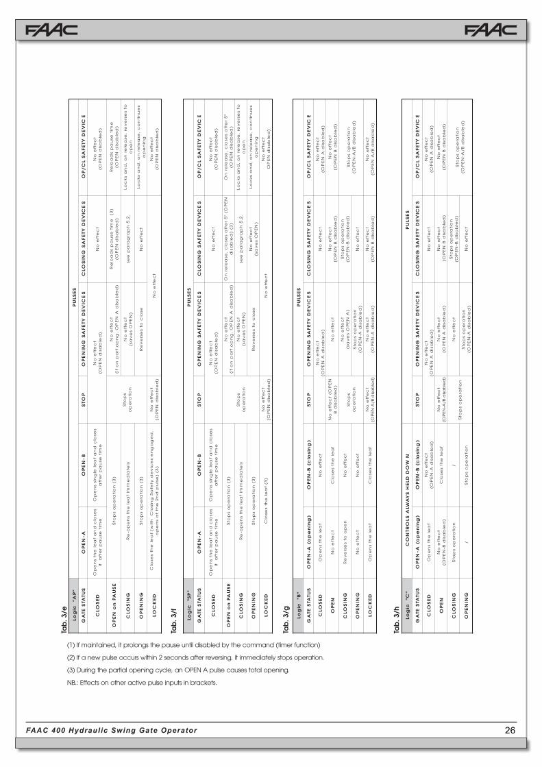
(1) If maintained, it prolongs the pause until disabled by the command (timer function)
(3) During the partial opening cycle, an OPEN A pulse causes total opening.
(2) If a new pulse occurs within 2 seconds after reversing, it immediately stops operation.
NB.: Effects on other active pulse inputs in brackets.
14. OPERATING MODES DETAILED DESCRIPTION
26FAAC 400 Hydraulic Swing Gate Operator
Tab
. 3/e
Tab
. 3/f
Tab
. 3/g
Tab
. 3/h
"C"
cig
oLN
WO
DDL
EH
SY
AWL
ASL
ORT
NO
CS
ESL
UP
SUT
ATS
ETA
G)
gni
ne
po(
A-N
EP
O)
gnis
olc(
B-N
EP
OP
OTS
SE
CIV
ED
YTE
FA
SG
NIN
EP
OS
ECI
VE
DYT
EF
AS
GNI
SOL
CE
CIV
ED
YTE
FA
SL
C/P
O
DE
SOL
Cf
ael
eht
sn
ep
Ot
ceff
eo
N)
del
basi
dA-
NE
PO(
tc
effe
oN
)d
elb
asid
AN
EP
O(t
ceff
eo
Nt
ceff
eo
N)
del
basi
dA
NE
PO(
NE
PO
tc
effe
oN
)d
elb
asid
B-N
EP
O(f
ael
eht
ses
olC
tc
effe
oN
)d
elb
asid
B/A-
NE
PO(
tc
effe
oN
)d
elb
asid
AN
EP
O(t
ceff
eo
N)
del
basi
dB
NE
PO(
tc
effe
oN
)d
elb
asid
BN
EP
O(
GNI
SOL
Cn
oitar
ep
os
pot
S/
noit
are
po
sp
otS
tc
effe
oN
noit
are
po
sp
otS
)d
elb
asid
B-N
EP
O(n
oitar
ep
os
pot
S)
del
basi
dB
/A-
NE
PO(
GNI
NE
PO
/n
oitar
ep
os
pot
Sn
oitar
ep
os
pot
S)
del
basi
dA-
NE
PO(
tc
effe
oN
"B"
cig
oLS
ESL
UP
SUT
ATS
ETA
G)
gni
ne
po(
A-N
EP
O)
gnis
olc(
B-N
EP
OP
OTS
SE
CIV
ED
YTE
FA
SG
NIN
EP
OS
ECI
VE
DYT
EF
AS
GNI
SOL
CE
CIV
ED
YTE
FA
SL
C/P
O
DE
SOL
Cf
ael
eht
sn
ep
Ot
ceff
eo
Nt
ceff
eo
N)
del
basi
dA
NE
PO(
tc
effe
oN
tc
effe
oN
)d
elb
asid
AN
EP
O(
NE
PO
tc
effe
oN
fa
ele
hts
esol
CN
EP
O(t
ceff
eo
N)
del
basi
dB
tc
effe
oN
tc
effe
oN
)d
elb
asid
BN
EP
O(t
ceff
eo
N)
del
basi
dB
NE
PO(
GNI
SOL
Cn
ep
oot
sesr
ev
eR
tc
effe
oN
sp
otS
noit
are
po
tc
effe
oN
)A
NE
PO
se
vas(
noit
are
po
sp
otS
)d
elb
asid
B-N
EP
O(n
oitar
ep
os
pot
S)
del
basi
dB
/A-
NE
PO(
GNI
NE
PO
tc
effe
oN
tc
effe
oN
noit
are
po
sp
otS
)d
elb
asid
A-N
EP
O(t
ceff
eo
N
DE
KC
OLf
ael
eht
sn
ep
Of
ael
eht
ses
olC
tc
effe
oN
)d
elb
asid
B/A
NE
PO(
tc
effe
oN
)d
elb
asid
A-N
EP
O(t
ceff
eo
N)
del
basi
dB
NE
PO(
tc
effe
oN
)d
elb
asid
B/
AN
EP
O(
(1) If maintained, it prolongs the pause until disabled by the command (timer function)
(3) During the partial opening cycle, an OPEN A pulse causes total opening.
(2) If a new pulse occurs within 2 seconds after reversing, it immediately stops operation.
NB.: Effects on other active pulse inputs in brackets.
"P
A"ci
goL
SE
SLU
P
SUT
ATS
ETA
GA-
NE
PO
B-N
EP
OP
OTS
SE
CIV
ED
YTE
FA
SG
NIN
EP
OS
ECI
VE
DYT
EF
AS
GNI
SOL
CE
CIV
ED
YTE
FA
SL
C/P
O
DE
SOL
Cs
esol
cd
na
fa
ele
hts
ne
pO
emit
esu
ap
retf
ati
ses
olc
dn
af
ael
elg
niss
ne
pO
emit
esu
ap
retf
at
ceff
eo
N)
del
basi
dN
EP
O(t
ceff
eo
Nt
ceff
eo
N)
del
basi
dN
EP
O(
ES
UAP
no
NE
PO
)3(
noit
are
po
sp
otS
sp
otS
noit
are
po
tc
effe
oN
)d
elb
asid
AN
EP
O.
gn
po.tr
ap
no
fi()
3(e
mites
ua
ps
da
ole
R)
del
basi
dN
EP
O(e
mites
ua
ps
da
ole
R)
del
basi
dN
EP
O(
GNI
SOL
Cyl
etai
de
mmi
fa
ele
hts
ne
po-
eR
tc
effe
oN
)N
EP
Os
ev
as(.
2.5
hp
arg
ara
pe
esot
sesr
ev
er,
esa
eler
no
,d
na
sk
co
Ln
ep
o
GNI
NE
PO
)3(
noit
are
po
sp
otS
esol
cot
sesr
ev
eR
tc
effe
oN
se
unit
no
c,
esa
eler
no
,d
na
sk
co
Lg
nin
ep
o
DE
KC
OL,
de
ga
gn
es
eci
ve
dyt
efa
Sg
nisol
Chti
w(f
ael
eht
ses
olC
)3(
)esl
up
dn
2e
htt
as
ne
po
tc
effe
oN
)d
elb
asid
NE
PO(
tc
effe
oN
tc
effe
oN
)d
elb
asid
NE
PO(
"P
S"ci
goL
SE
SLU
P
SUT
ATS
ETA
GA-
NE
PO
B-N
EP
OP
OTS
SE
CIV
ED
YTE
FA
SG
NIN
EP
OS
ECI
VE
DYT
EF
AS
GNI
SOL
CE
CIV
ED
YTE
FA
SL
C/P
O
DE
SOL
Cs
esol
cd
na
fa
ele
hts
ne
pO
emit
esu
ap
retf
ati
ses
olc
dn
af
ael
elg
niss
ne
pO
emit
esu
ap
retf
at
ceff
eo
N)
del
basi
dN
EP
O(t
ceff
eo
Nt
ceff
eo
N)
del
basi
dN
EP
O(
ES
UAP
no
NE
PO
)3(
noit
are
po
sp
otS
sp
otS
noit
are
po
tc
effe
oN
)d
elb
asid
AN
EP
O.
gn
po.tr
ap
no
fi(N
EP
O("
5r
etfa
ses
olc
,es
ael
ern
O)
3()
del
basi
d"
5r
etfa
ses
olc
,es
ael
ern
O)
del
basi
dN
EP
O(
GNI
SOL
Cyl
etai
de
mmi
fa
ele
hts
ne
po-
eR
tc
effe
oN
)N
EP
Os
ev
as(.
2.5
hp
arg
ara
pe
esot
sesr
ev
er,
esa
eler
no
,d
na
sk
co
Ln
ep
o
GNI
NE
PO
)3(
noit
are
po
sp
otS
esol
cot
sesr
ev
eR
tc
effe
oN
)N
EP
Os
ev
as(s
eu
nitn
oc
,es
ael
ern
o,
dn
as
kc
oL
gni
ne
po
DE
KC
OL)
3(f
ael
eht
ses
olC
tc
effe
oN
)d
elb
asid
NE
PO(
tc
effe
oN
tc
effe
oN
)d
elb
asid
NE
PO

27FAAC 400 Hydraulic Swing Gate Operator
15. PREWIRED ENCLOSURE DIAGRAM
28FAAC 400 Hydraulic Swing Gate Operator
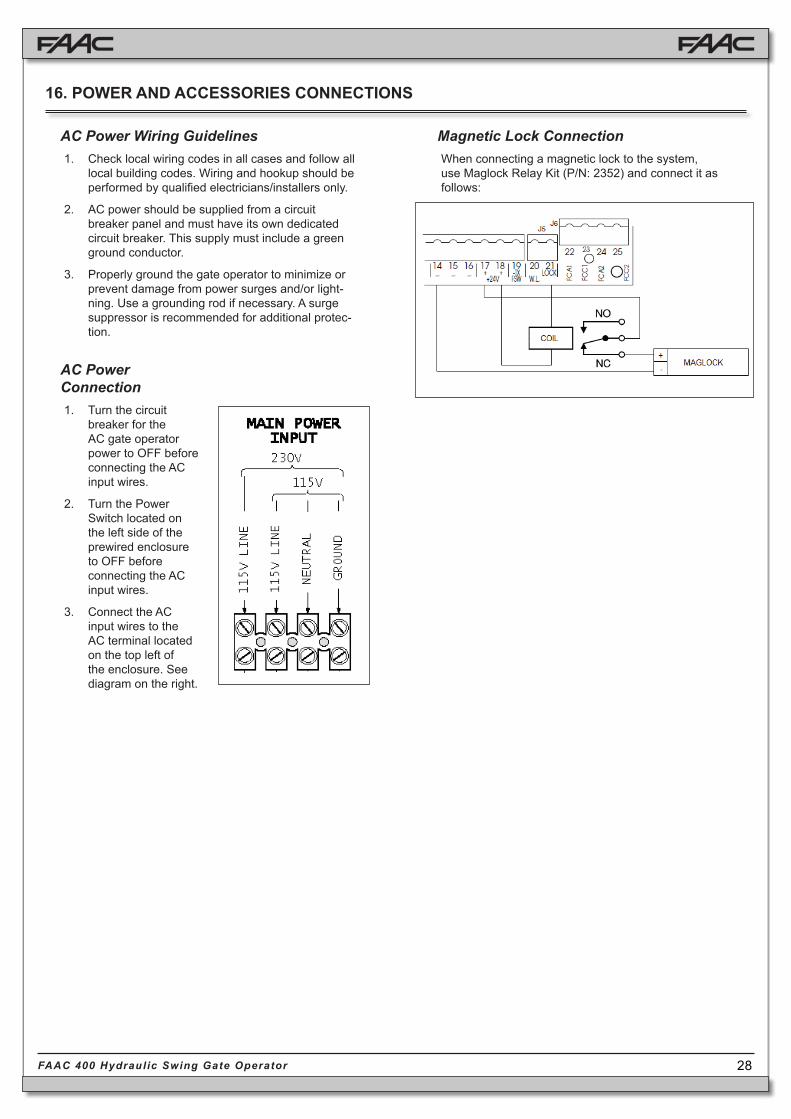
AC Power Wiring Guidelines1. Check local wiring codes in all cases and follow all
local building codes. Wiring and hookup should be performed by qualified electricians/installers only.
2. AC power should be supplied from a circuit breaker panel and must have its own dedicated circuit breaker. This supply must include a green ground conductor.
3. Properly ground the gate operator to minimize or prevent damage from power surges and/or light-ning. Use a grounding rod if necessary. A surge suppressor is recommended for additional protec-tion.
AC Power Connection1. Turn the circuit
breaker for the AC gate operator power to OFF before connecting the AC input wires.
2. Turn the Power Switch located on the left side of the prewired enclosure to OFF before connecting the AC input wires.
3. Connect the AC input wires to the AC terminal located on the top left of the enclosure. See diagram on the right.
Magnetic Lock ConnectionWhen connecting a magnetic lock to the system, use Maglock Relay Kit (P/N: 2352) and connect it as follows:
16. POWER AND ACCESSORIES CONNECTIONS

29FAAC 400 Hydraulic Swing Gate Operator
17. TROUBLESHOOTING
The following table may help you identify and resolve some common problems.
CONDITION SUGGESTIONA Gate does not move. • Check that main power is supplied.
• Ensure that the operator is not unlocked (see Section 8).
• Check the adjustment of the anti-crushing system (see Section 4.1).
• Check the connection and operation of the thrust capacitor.
• Check functionality of the electronic control unit.
• Ensure that the torque/force is set to a maximum of 50 in programming.
• Verify that the LEDs FSWOP, FSWCL, and STOP are illuminated. If they are not illuminated, be sure that you have closed circuits in the stop and reversing inputs.
• Verify that your activating device works properly. OP_A should illumi-nate when you signal the gate to open. If OP_A does not illuminate when you signal the gate, then the problem may be in your activating device. Place a short across terminals 9 and 14. If the short causes the gate to open, then the problem is in the activating device.
• Check oil level inside the tank (see Section 10, Fig. 18).B Gate does not open (or close), though
the motor is running.• Make sure that the motor is running in the right direction.
• Make sure the Manual Release mechanism has fully engaged the hydraulic system.
• Increase the bypass pressure in small ¼-turn increments to determine if the hydraulic system needs more pressure.
C Gate opens but doesn’t close. Verify that the reversing devices are working properly. FSWOP and FSWCL should be illuminated except when a reversing device is trig-gered. If either does not illuminate, then one of your reversing devices is preventing the gate from responding to your signal. Check your revers-ing devices. If no reversing devices are installed, make sure a circuit is installed between appropriate terminals.
D Gate moves slowly. Check the adjustment of the anti-crushing system (see Section 4.1).E Gate doesn’t fully open (or fully close). • Increase the bypass pressure to determine if the hydraulic system
needs more pressure.
• Check the operator’s open / close time selection. You should set a time that is just longer than the rated speed of your model of operator. For example, the 400 CBAC has an opening time of 17 seconds, therefore you should set the time to 20 or 25 seconds.
• Check to see that there are no obstructions in the path of the gate or that the hinges are not binding.
F Gate jerks as it moves. • Make sure that you have removed the breather screw (see Section 5).
• Run several complete gate opening and closing cycles, in order to release any air inside the piston.
• Make sure that a flexible gate leaf is not the problem. If the gate leaf flexes, then stiffen the gate or use a slower operator.
G Operator is losing oil from breather screw.
Initially, a small amount of oil leakage is normal. A larger leak may occur if the operator is not fitted in a perfectly horizontal plane. If the oil leak continues and/or increases, contact an FAAC authorized repair center.
H Leaves stop at slow-down. Check the adjustment of the anti-crushing system (see Section 4.1).I Gate speed not constant. Incorrect installation dimensions (see Section 3.2).

30FAAC 400 Hydraulic Swing Gate Operator
To the original purchaser only:
FAAC International, Inc., warrants, for twenty-four (24) months from the date of invoice, the gate operator systems and other related sys-tems and equipment manufactured by FAAC S.p.A. and distributed by FAAC International, Inc., to be free from defects in material and workmanship under normal use and service for which it was intended provided it has been prop-erly installed and operated.
FAAC International, Inc.’s obligations under this warranty shall be limited to the repair or exchange of any part of parts manufactured by FAAC S.p.A. and distributed by FAAC Interna-tional, Inc. Defective products must be returned to FAAC International, Inc., freight prepaid by purchaser, within the warranty period. Items returned will be repaired or replaced, at FAAC International, Inc.’s option, upon an examination of the product by FAAC International, Inc., which discloses, to the satisfaction of FAAC Interna-tional, Inc., that the item is defective. FAAC International, Inc. will return the warranted item freight prepaid. The products manufactured by FAAC S.p.A. and distributed by FAAC Inter-national, Inc., are not warranted to meet the specific requirements, if any, of safety codes of any particular state, municipality, or other jurisdiction, and neither FAAC S.p.A. or FAAC International, Inc., assume any risk or liabil-ity whatsoever resulting from the use thereof, whether used singly or in combination with other machines or apparatus.
Any products and parts not manufactured by FAAC S.p.A. and distributed by FAAC Interna-tional, Inc., will carry only the warranty, if any, of the manufacturer. This warranty shall not ap-ply to any products or parts thereof which have been repaired or altered, without FAAC Interna-tional, Inc.’s written consent, outside of FAAC International, Inc.’s workshop, or altered in any way so as, in the judgment of FAAC Interna-tional, Inc., to affect adversely the stability or reliability of the product(s) or has been subject to misuse, negligence, or accident, or has not been operated in accordance with FAAC Inter-national, Inc.’s or FAAC S.p.A.’s instructions or has been operated under conditions more severe than, or otherwise exceeding, those set forth in the specifications for such product(s). Neither FAAC S.p.A. nor FAAC International, Inc., shall be liable for any loss or damage whatsoever resulting, directly or indirectly, from the use or loss of use of the product(s). Without
limiting the foregoing, this exclusion from liability embraces a purchaser’s expenses for downtime or for making up downtime, damages for which the purchaser may be liable to other persons, damages to property, and injury to or death of any persons.
FAAC S.p.A. or FAAC International, Inc., neither assumes nor authorizes any person to assume for them any other liability in connection with the sale or use of the products of FAAC S.p.A. or FAAC International, Inc. The warranty herein above set forth shall not be deemed to cover maintenance parts, including, but not limited to, hydraulic oil, filters, or the like. No agreement to replace or repair shall constitute an admission by FAAC S.p.A. or FAAC International, Inc., of any legal responsibility to effect such replace-ment, to make such repair, or otherwise. This limited warranty extends only to wholesale cus-tomers who buy directly through FAAC Interna-tional, Inc.’s normal distribution channels. FAAC International, Inc., does not warrant its products to end consumers.
Consumers must inquire from their selling dealer as to the nature and extent of that dealer’s war-ranty, if any. This warranty is expressly in lieu of all other warranties expressed or implied includ-ing the warranties of merchantability and fitness for use. This warranty shall not apply to prod-ucts or any part thereof which have been sub-ject to accident, negligence, alteration, abuse, or misuse or if damage was due to improper installation or use of improper power source, or if damage was caused by fire, flood, lightning, electrical power surge, explosion, wind storm, hail, aircraft or vehicles, vandalism, riot or civil commotion, or acts of God.
LIMITED WARRANTY
532020 Rev. A