fabrication methods of the polygonal masonry of large
TRANSCRIPT

Fabrication methods of the polygonal masonry of large stone blocks with fitted curved surfaces in megalithic structures of Peru
Rostislav V. Lapshin, Ph. D. Institute of Physical Problems Zelenograd, Russian Federation E-mail: [email protected]
The article suggests methods that allow creating the most complicated type of polygonal masonry found in Peru. This masonry consists of large stone blocks weighing from several hundred kilograms to several tons fitted close to each other almost without a gap between complicated curved surfaces of large area. The work provides a brief description of techniques, which apparently were used by builders who arrived from Europe. The techniques under discussion are based on the use of a reduced clay model, 3D-pantograph and replicas. The use of a reduced clay model and a pantograph provides not only the unique appearance and high quality of masonry with large blocks, but also allows to significantly in-crease the productivity of the builders. As the pantograph designed to work with three-dimensional ob-jects has been known since the 18th century, the constructions under consideration should be dated by that and later time. The remaining simpler types of polygonal masonry with smaller stones or fitted sur-faces are almost flat, or stones contact with each other by a small area, or there are significant gaps be-tween stones, are quite consistent with the well-known methods of stone processing of those and earlier years, and, therefore, they do not require any additional explanations.
The material was firstly published on April 11, 2021 in the author's blog.
Key words: stone block, polygonal masonry, clay model, pantograph, replica, chisel, hammer, megalith, Inca, Cusco, Ollantaytambo, Machu Picchu, Peru
Copyright © 2021 R. V. Lapshin, published under Creative Commons Attribution
1. Introduction
Polygonal masonry is a type of masonry made of natural stone. Stones having an initially arbi-trary shape are processed in such a way that form irregular polygons tightly adjacent to each other on the front side of the structure. It should be noted that the name “polygonal masonry” is largely conditional. The fact is that there are many structures classified as polygonal in which stone “polygons” have curved sections besides the linear ones. A feature of the polygonal ma-sonry is that it does not require a building mortar (dry masonry). The polygonal masonry pos-sesses sufficient strength and stability to withstand moderate earthquakes.
In the present paper, a polygonal masonry in the megalithic structures located on the territory of modern Peru is under consideration. The main attention is paid to the masonry consisting of large stone blocks weighing from several hundred kilograms to several tons fitted close to each other almost without a gap between curved surfaces of large area. The remaining simpler types of polygonal masonry, when the stones are small or the mating surfaces are almost flat, or the stones contact each other over a small area, or there are significant gaps between the stones, are quite consistent with the well-known since the ancient times methods of stone processing and, therefore, do not require any special explanation.
In general, a polygonal masonry is not something unprecedented, such masonry has been known in Europe since antiquity. In the Peruvian version, only the quality of the curved inter-faces is striking, which is not easy to repeat even in our time. The methods suggested by both the scientific community1 and the enthusiasts2, 3 for fabrication of the Peruvian polygonal ma-sonry do not explain all the observed features and are often far from a reality.
If we look at the shape of the stones in the masonry closely, at the sites of their almost perfect fitting, then there is a feeling that the stones were not processed mechanically but were sculpted. In this regard, many researchers mistakenly decided that the stones were sculpted or cast from a certain plastic mixture – artificial granite, concrete, lime, rock softened by heating, and so on.2, 3 In this regard, the question immediately arises: why produce an expensive plastic
Preprints (www.preprints.org) | NOT PEER-REVIEWED | Posted: 3 August 2021 doi:10.20944/preprints202108.0087.v1
© 2021 by the author(s). Distributed under a Creative Commons CC BY license.

Fabrication methods of the polygonal masonry in megalithic structures of Peru
Copyright © 2021 R. V. Lapshin, published under CC BY 2
mixture when there is a lot of ready-to-use material around – natural stone of arbitrary shape? What is even more unclear is: why should plastic mixture be given such complex forms? Why not make stone blocks the same size, for example? There are other arguments against the plastic version. For example, the backside of many blocks is a ragged stone, there is no plastic mixture flowed into the interblock spaces inside the masonry, etc.4
The methods of polygonal masonry fabrication proposed by the author are based on the use of a reduced clay model, a 3D-pantograph,5 and replicas. The main tools for stone processing are a hammer and a steel chisel. The use of the reduced clay model and the pantograph provides not only the unique appearance and high quality of masonry of large blocks, but also allows to significantly increase the productivity of the builders. Only due to the high productivity it became possible to carry out the volumes of the polygonal construction revealed in Peru. As the panto-graph designed to work with three-dimensional objects has been known since the 18th century, the polygonal constructions under consideration should be dated beginning from that time.
Since to the moment of the South America conquest by Europeans, the Indians did not know neither iron tools nor wheel, and did not have draft animals, the structures under consideration could only be erected by the builders who come from Europe. Unlike the Indians, these builders had all the necessary tools, mechanisms, and skills for the large-scale construction. The marks of this large-scale stone construction are visible everywhere – Catholic cathedrals, monasteries, palaces, villas, and a lot of urban and industrial buildings. Any large-scale construction always implies the existence of an economy corresponding to this scale. Therefore, the article addition-ally explains what the economy of Peru was based on in those years.
2. Methods of fabrication of the polygonal masonry
2.1. Clay model shape transfer to a stone billet by means of a pantograph
First, in accordance with a sketch, the clay model of a structure is made in a reduced scale which blocks form a polygonal masonry. Let us assume for a certainty that the structure is just a wall. Small polygonal blocks of the planned shape are sculpted from clay. The size of these blocks correspond to the size, say, of a basketball or so. The interface between the fitted sur-faces is formed by pressing the blocks into each other.
The model of the wall is assembled from the raw model blocks. During the assembly, some ma-terial is laid between the blocks that prevents the blocks from sticking to each other during the drying-solidification process. To reduce the influence of the shrinkage effect, the bottom course is dried first, then the next course, and so on. If necessary, the wall is given the required slope. During the drying shrinkage process, the model blocks are matched more closely under their own weight and with small corrections of the builder.
After the solidification of the model of the wall, it is disassembled. Now the “magic” began. Me-dieval European builders transferred the surface topography from a small model clay block to a large stone billet of suitable sizes and shape with a specified scale using a 3D-pantograph,5 a hammer, and a steel chisel.
The pantograph is a simple lever device based on a parallelogram mechanism. A 2D-pantograph allows to proportionally enlarge/reduce a flat drawing.6 Being a logical advancement of the 2D-pantograph, a more complicated 3D-pantograph7 (see Fig. 1) allows to proportionally enlarge/reduce a space figure, for example, a statue. In our case, using the 3D-pantograph, the enlarged copy of a small clay model of the block is obtained by processing the stone billet with a hammer and a chisel.
The parallelogram mechanism is located on the boom of the 3D-pantograph. The boom is at-tached to the frame using a spherical joint (see Pivot in Fig. 1). The boom has a counterweight. A sharp probe is fixed on one arm of the parallelogram mechanism (Pointer A), on the other – a pointer (a part actually similar to the probe; Pointer B in Fig. 1). If someone touches the clay model with a probe, the pointer will show where the corresponding point of the enlarged copy is
Preprints (www.preprints.org) | NOT PEER-REVIEWED | Posted: 3 August 2021 doi:10.20944/preprints202108.0087.v1

R. V. Lapshin
Copyright © 2021 R. V. Lapshin, published under CC BY 3
located in space. The enlargement coefficient is set by the appropriate adjustment of arms of the lever system. The model and its enlarged copy are located each on their rotary platform (Table A and Table B, respectively). Due to a chain transmission, the platforms can be synchro-nously rotated around their vertical axes, putting different sides of the object under the probe/pointer.
A minimum size of the model clay block depends on the size of the stone block under fabrica-tion and, ultimately, is determined by the error of the pantograph mechanism. The size of the model block is also determined by how convenient it is for one or two workers to handle (sculpt, correct, carry, install, shift, turn, etc.) such a block. The modern 3D-pantographs used by sculp-tors7 (see Fig. 1) allow enlargement of the object model by up to 6 times. Thus, by a clay block
Fig. 1. Modern 3D-pantograph (photo by M. Keropian)
Preprints (www.preprints.org) | NOT PEER-REVIEWED | Posted: 3 August 2021 doi:10.20944/preprints202108.0087.v1

Fabrication methods of the polygonal masonry in megalithic structures of Peru
Copyright © 2021 R. V. Lapshin, published under CC BY 4
model size, say, 50×50×50 cm3, which can be made hollow to reduce weight, the stone blocks up to 3×3×3 m3 can be processed on a not very large pantograph.
After the mentioned copying process with the specified scale, the wall of stone blocks is assem-bled without any significant adjustments using rollers, levers, blocks, winches, and primitive cranes of the time.
The proposed method of geometry transfer from a small clay model to a large stone block using a 3D-pantograph does not require the detailed drawing of the block geometry. The builder should actually sculpt approximately the desired interface between the model blocks in accor-dance to the general idea of the sketch with his own hands, then lay this block in the model wall, where this block would be finally fitted to the neighboring model blocks under its own weight and with small corrections of the builder. No precise dimensions need to be held.
2.2. Usage of replicas
Not very complicated interfaces between large blocks are fabricated using replicas. A “pancake” of a constant thickness is pressed/rolled out of the clay. The raw pancake is put on a stone block which surface replica should be made. After solidification, the replica-pancake is taken off. By periodically applying the obtained low weight replica-pancake to the stone block intended for fabrication of the mating part of the masonry, the excess material is gradually removed in the needed areas until full fitting of the replica to the block.
If a higher accuracy of the relief transfer is required than the replica-pancake is capable to pro-vide, then a replica of the replica is produced. First, by applying a lump of raw clay to the se-lected area of the stone block, an imprint of its surface is made. After solidification, another im-print is made in raw clay by the obtained replica. After drying, the replica of the replica is further used as a copy of the surface of the stone block when making the mating part of the stone ma-sonry.
19th century workshop of statues copying using a 3D-pantograph
Preprints (www.preprints.org) | NOT PEER-REVIEWED | Posted: 3 August 2021 doi:10.20944/preprints202108.0087.v1
R. V. Lapshin
Copyright © 2021 R. V. Lapshin, published under CC BY 5
In another method, a clay rim is installed along the perimeter of the selected area of the stone block, after that the resulting container is filled with gypsum. After solidification, the obtained replica is imprinted in a raw clay or, having installed a rim, one fill the resulting container with gypsum (the surface of the gypsum mold is precovered with a substance preventing bonding of the poured gypsum to the gypsum mold). After drying, the resulting replica of the replica is fur-ther used as a copy of the surface of the stone block when making the mating part of the stone masonry.
The advantage of the replica is that just one of the mating surfaces of the adjacent blocks is processed upon a model (replica); the original surface is processed arbitrarily (independently). In contrast to the replica, it is necessary to process both mating surfaces according to the model in the pantograph method. There are no arbitrarily processed surfaces in the pantograph method.
2.3. The main problem
What does a stonemason has to continuously do while fabricating blocks fitted to each other through a complicated profile? The stonemason has to repeatedly apply one stone to another in order to determine the areas where the excess material should be removed. When the stones are small, it is easy to do. But how to do this when the weight of the stones is hundreds of kilo-grams or several tons? The suggested methods just allow us to solve this problem. It is no longer necessary to repeatedly move a heavy matching block.
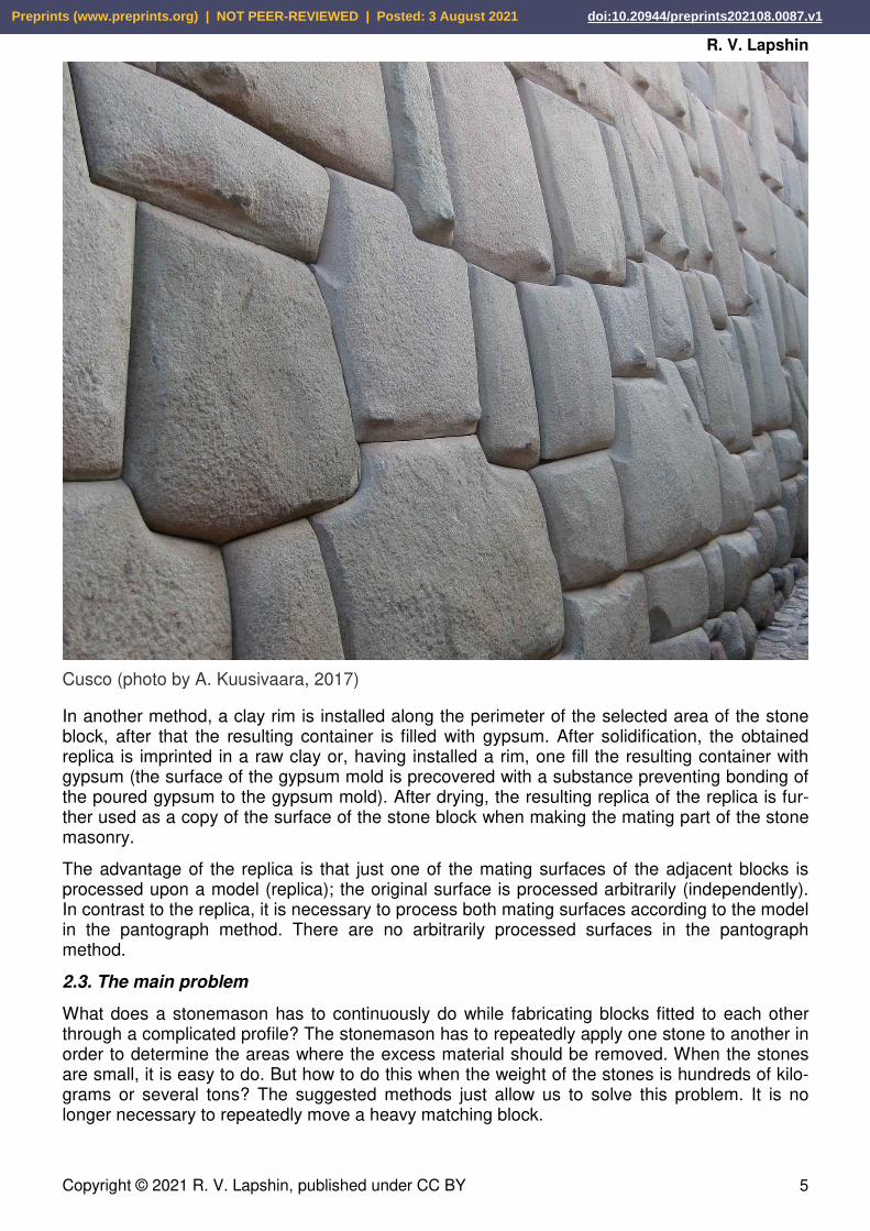
Cusco (photo by A. Kuusivaara, 2017)
Preprints (www.preprints.org) | NOT PEER-REVIEWED | Posted: 3 August 2021 doi:10.20944/preprints202108.0087.v1

Fabrication methods of the polygonal masonry in megalithic structures of Peru
Copyright © 2021 R. V. Lapshin, published under CC BY 6
2.4. What else a clay model of the object is needed for?
It is always extremely useful to have a small model of an object consisting of many parts of a complicated shape connected to each other in a complicated way; to turn each block in hands; to evaluate proportions more precisely; to correct the blocks if something is not likable in their shape or fitting; to assemble/disassemble the model wall to check for the fundamental possibil-ity of assembling an object containing key elements; to assemble/disassemble the model wall to analyze the operations for moving, mounting, and installing heavy stone blocks; to see in ad-vance how the object will look after construction completion. After all, in those days, architects and builders had no computers to rotate a component in three-dimensional space on a monitor screen or, creating a virtual reality, wander around the future construction long time before its erection. Even in our time, the making of scale models in architecture and planning has not lost its relevance.
It is well-known that the region, where the polygonal masonry was used, is earthquake-prone.8 Therefore, by creating a model of the building with lock blocks and shaking it, one could see how the object would behave in an earthquake, and then, if necessary, make appropriate cor-rections to the project. Other methods did not simply exist in those times, the calculations were rough, and intuition and experience could fail.
On the upper faces of a number of stone blocks, characteristic recesses for the bases of the blocks installed over draw attention. Some of these recesses spread over two or even three ad-jacent blocks thereby providing bonding of the blocks. The recesses ensure in accordance with the principles of stable equilibrium that the blocks would return to their initial position in the event of a small horizontal displacement caused by an earthquake. The recesses under consid-eration in the upper faces of the blocks and the corresponding protruding parts at the lower faces of the blocks installing over are fabricated while sculpturing the clay model.
Since the clay model of the wall is building bottom-up and drying course after course, then, in theory, the shallow recesses should occur naturally in the bases of the model blocks, which be-
Cusco (photo by Gvillemin, 2008)
Preprints (www.preprints.org) | NOT PEER-REVIEWED | Posted: 3 August 2021 doi:10.20944/preprints202108.0087.v1

R. V. Lapshin
Copyright © 2021 R. V. Lapshin, published under CC BY 7
ing softer (wet) weight down on the harder (dry) blocks located under them. The materials avail-able to date do not allow us to confirm or disprove the presence of such recesses with certainty.
2.5. What are the advantages of a pantograph over a replica?
When we bring a replica to a processing surface with a complicated extensive topography, we do not see clearly the locations and amount of material to be removed. Therefore, when working with a replica, we need to mark it with something, say, chalk or charcoal, and, while applying it to the processing surface area, slightly rub it to mark the locations where the material should be removed. Remember, what the dentist does after filling the tooth. He puts a piece of carbon pa-per on the filling and asks to close your mouth and slightly rub it with teeth. After that, the dentist removes a little bit of the filling material in the marked place. Then he repeats the process sev-eral times, until the teeth when closing take the usual position.
Working with a pantograph, a sharp probe (Pointer A) is applied to the clay model, and a pointer (Pointer B) mechanically connected to the probe by means of a parallelogram mechanism is applied to the processing surface of the billet. In contrast to the replica, due to the small area of the probe and the pointer, the topography measurement is actually carried out at a surface point, and it is clearly visible at what exact point; the entire surface is completely open.
Moreover, the pantograph allows one to clearly determine the thickness of the material to be removed at any point to which the pointer is directed. Therefore, the excess material can be re-moved for significantly fewer attempts. All these result in increasing productivity abruptly. The highest productivity is achieved when two people work on a pantograph. One person with a pantograph pointer shows a location (point) on the stone billet and reports the thickness of ma-
Cusco (photo by S. N. Kozintsev)
Preprints (www.preprints.org) | NOT PEER-REVIEWED | Posted: 3 August 2021 doi:10.20944/preprints202108.0087.v1
Fabrication methods of the polygonal masonry in megalithic structures of Peru
Copyright © 2021 R. V. Lapshin, published under CC BY 8
terial that should be removed at this point, and the other person with a hammer and a chisel removes the specified amount of the material.
Another advantage of the pantograph in comparison with the replica is that it is much faster and easier to apply an almost weightless probe (the device is balanced by a counterweight) to the clay model of the block than to apply a relatively heavy replica to a stone billet, and then in addi-tion to slightly rub with this replica by the billet.
Also, the pantograph allows to easily keep proportions set by the architect, that, in case of the replicas, have to be done by eye by spending a long time by selecting billets of suitable size. Imagine that you need to accurately fit a structure into some unchangeable or difficult-to-change dimensions, say, between two rocky outcrops or into a cave. To do this, it is enough to measure the distance between the rocky outcrops, the size of the model, divide first by second and set the obtained enlargement factor in the pantograph.
What else does the use of the clay model blocks and the pantograph give? Let the outer side of the wall is needed to be made with a slope. To do this, it is sufficient to lay a raw clay model of the wall on the back side, to install the stops that set the required slope, to put a flat surface on top of the front side, to allocate suitable weights above. Instead of the weights, tightening clamps can be used. After some time, the clay model of the wall will be deformed properly. In this method, the specified angle can be kept very accurately along the whole length of the wall.
Another advantage of the pantograph is that by installing a stone billet on it, a clay model of the block suitable for this billet can be quickly selected. This feature is extremely useful exactly in the case of the polygonal type of masonry, since in such masonry, blocks often have a compli-cated shape that requires a lot of preliminary measurements while selecting a billet.
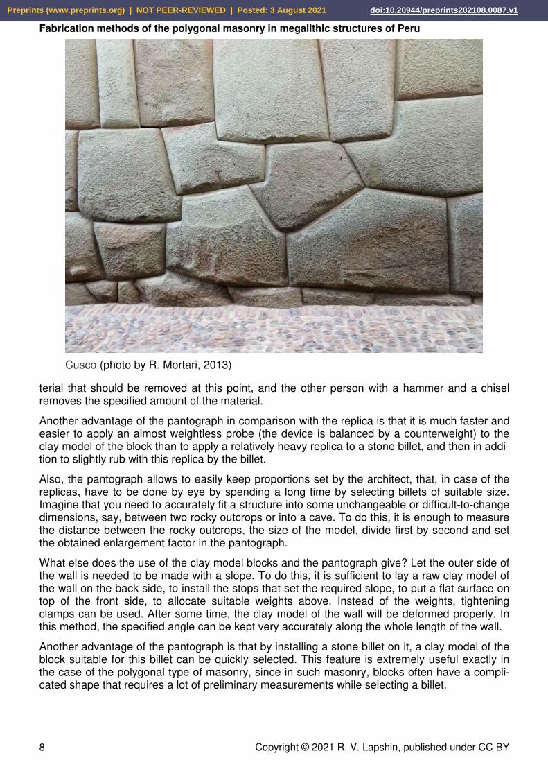
Cusco (photo by R. Mortari, 2013)
Preprints (www.preprints.org) | NOT PEER-REVIEWED | Posted: 3 August 2021 doi:10.20944/preprints202108.0087.v1
R. V. Lapshin
Copyright © 2021 R. V. Lapshin, published under CC BY 9
2.6. Reverse approach: clay model creation by a stone billet, fabrication of an interface surface and its transfer to the stone billet
According to the method described above, first, a model was created by a sketch, and then a stone billet was selected for each block of the model. This approach allows us to repeat many times a section of the wall (if necessary, at different scales) using the same clay model each time. The drawback of the method is the large volume of the chipped off material of the stone billet. The analysis shows that a reverse method was mainly used for the polygonal masonry.
In the reverse method, first, a reduced clay model is created by a stone billet of arbitrary shape using the pantograph. To do this, a piece of raw clay is impaled on a pointed, say, four-sided metal pin located in the center of the rotating platform intended for a model (Table A in Fig. 1). Due to this pin, the model can be removed from the pantograph at any time and precisely re-turned to its original position. Clay is added to those places of the model where it is not enough. Removal of clay excess is carried out directly with the metal pointer (Pointer A in Fig. 1) of the pantograph, which probe (Pointer B) moves along the surface of the stone block vertically up, then a small turn of the platform with the billet (Table B) around the vertical axis, then down, again a small turn, again up, etc.7 Owing to the pantograph, creation of the clay model body does not take much time.
At the next stage, a prototype of the wall is assembled from the obtained clay model blocks. The blocks still have no specially prepared mounting surfaces. Taking into account the size and the shape of the blocks, each block location is defined in the wall prototype. An architect-builder approximately layouts the contours of the future interfaces on the clay model of the wall, which should reflect: a conceived style, ensure stability of the created polygonal masonry, and mini-mize the labor of processing of the mounting surfaces. Further on, according to the accepted layout, the clay is cut out in the model block regions by which the blocks will adjoin each other.
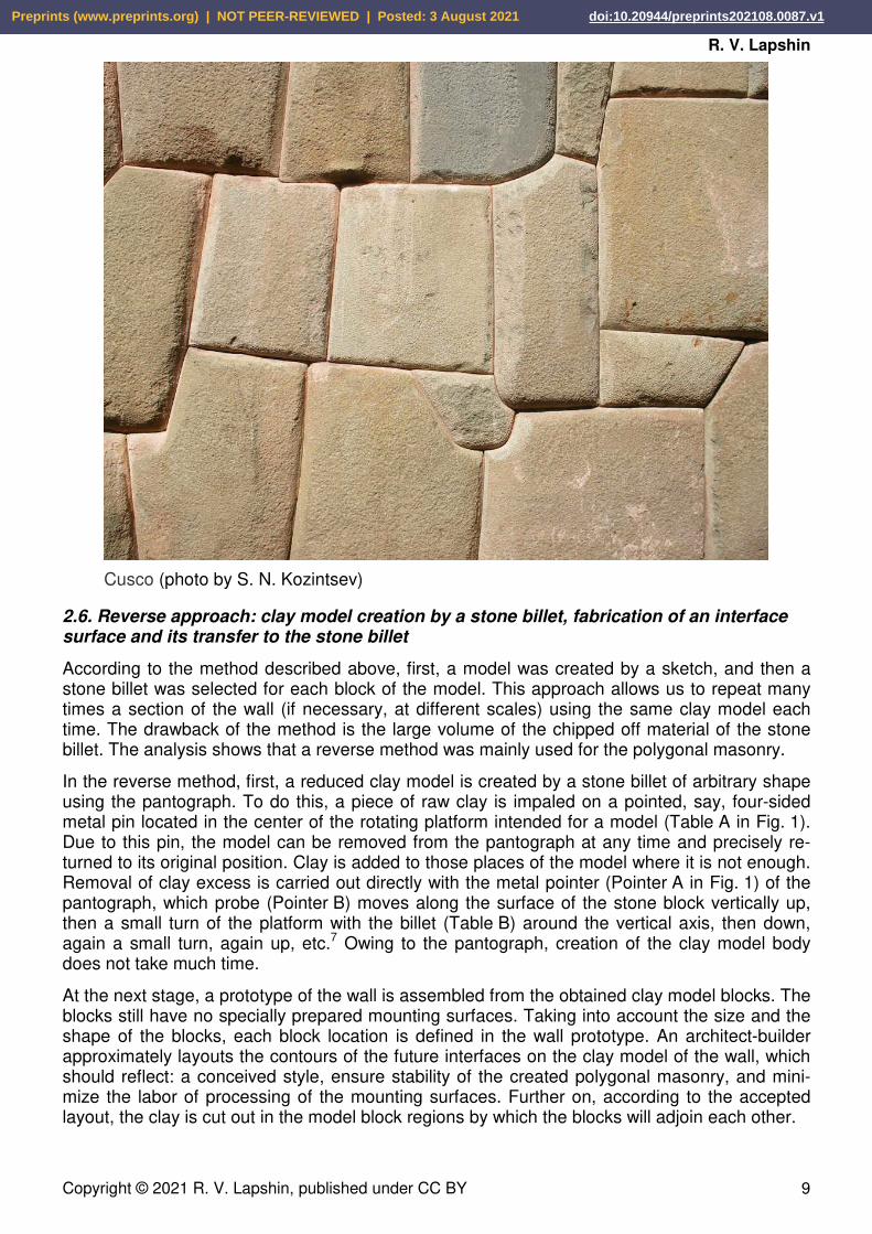
Cusco (photo by S. N. Kozintsev)
Preprints (www.preprints.org) | NOT PEER-REVIEWED | Posted: 3 August 2021 doi:10.20944/preprints202108.0087.v1

Fabrication methods of the polygonal masonry in megalithic structures of Peru
Copyright © 2021 R. V. Lapshin, published under CC BY 10
Next, the wall model is being assembled from the obtained model blocks. By small corrections, the blocks are matched more precisely to each other. If the block model was occasionally dam-aged during the manipulations, the shape of the model in any location can always be restored by placing the block model back on the pantograph (on the above indicated pin) and by compar-ing with the shape of the original stone billet. Then the wall is being dried. First, the bottom course is dried, then the next one, and so on. During the drying shrinkage process, the model blocks are matched more closely under their own weight.
At the final stage, the model wall is being disassembled. The clay model of the block is put back on the pantograph (on the above indicated pin) and the mounting sites are transferred on the stone billet corresponding to this model block using a hammer and a chisel.
2.7. Several more advantages of the pantograph
The use of a reduced clay model and a pantograph allows to fabricate blocks directly in the quarry where the stones are extracted. As a result, the finished stone blocks are carried from the quarry to the construction site. This approach significantly reduces the weight of the trans-ported blocks and decreases the volume of the whole cargo traffic. Moreover, such organization excludes a large amount of construction debris on the construction site, which needs to be also transported somewhere after all.
Both the pantograph method and the replica method use auxiliary elements. In the pantograph method, these are the clay model blocks; in the replica method, these are the replicas them-selves. To mate stone blocks in the replica method, the side surface of the block must be di-vided into several overlapping sections, each of which requires its own replica. If you mentally attach to the side surface of a non-edge stone block all the replicas made for it and by it, you
Ollantaytambo (photo by C. Jansen, M. Düerkop, 2016)
Preprints (www.preprints.org) | NOT PEER-REVIEWED | Posted: 3 August 2021 doi:10.20944/preprints202108.0087.v1
R. V. Lapshin
Copyright © 2021 R. V. Lapshin, published under CC BY 11
will get a kind of a wheel, i. e., a fairly massive formation. If a replica of replica is used, then there will be two such “wheels” already. Thus, it is necessary to fabricate one “wheel” of replicas for each non-edge block in the replica of replica method. Let us compare such a “wheel” of rep-licas with small model blocks in the pantograph-based method. The advantages of the panto-graph are obvious.
2.8. A method combining elements of the replica, clay model, and 3D-pantograph methods
In the beginning, every second stone block of the first course is installed on the site of the future structure. The empty positions between these blocks will be occupied by blocks, which will be fitted using a clay model and a pantograph to these initially installed blocks at the next stage. The base surfaces of the initially installed stone blocks are pre-treated properly to ensure their stability.
Besides the prepared base, the initially installed blocks have finally processed side faces also. The processing of the side faces is the straightening of the complicated initial shape of the stone billet by surfaces close to the planes with a hammer and a chisel. The faces of the initially
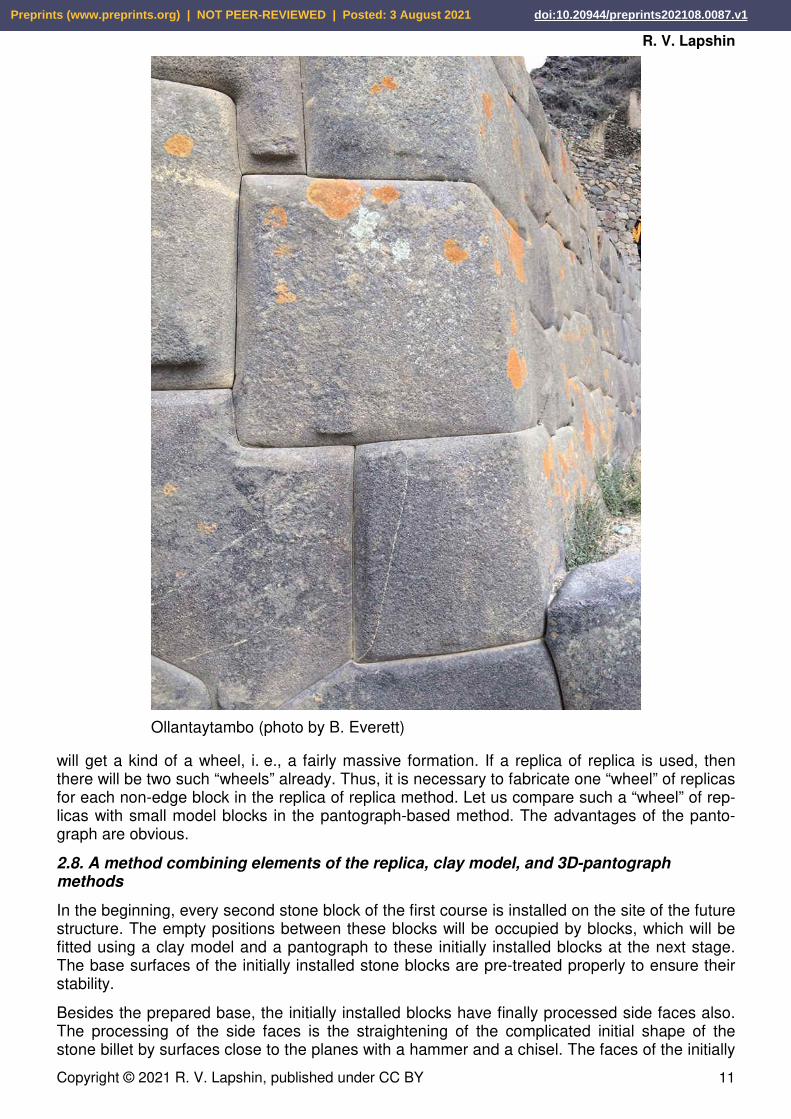
Ollantaytambo (photo by B. Everett)
Preprints (www.preprints.org) | NOT PEER-REVIEWED | Posted: 3 August 2021 doi:10.20944/preprints202108.0087.v1
Fabrication methods of the polygonal masonry in megalithic structures of Peru
Copyright © 2021 R. V. Lapshin, published under CC BY 12
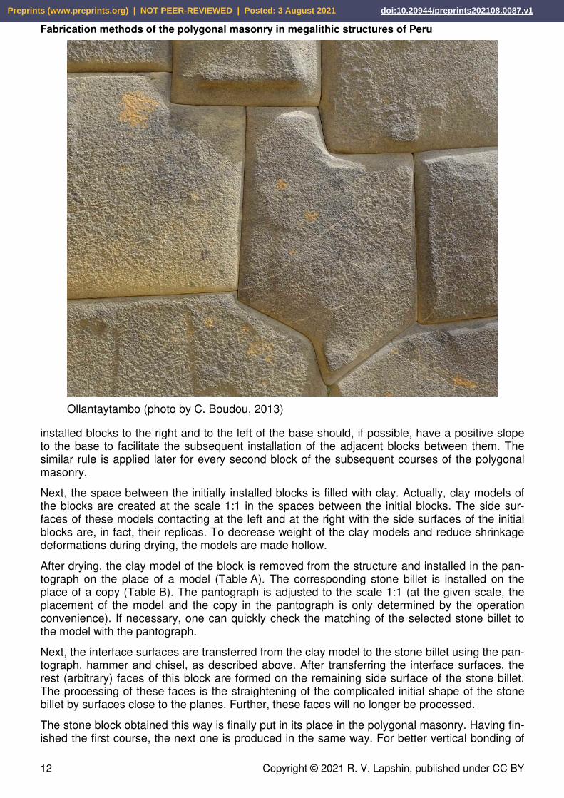
installed blocks to the right and to the left of the base should, if possible, have a positive slope to the base to facilitate the subsequent installation of the adjacent blocks between them. The similar rule is applied later for every second block of the subsequent courses of the polygonal masonry.
Next, the space between the initially installed blocks is filled with clay. Actually, clay models of the blocks are created at the scale 1:1 in the spaces between the initial blocks. The side sur-faces of these models contacting at the left and at the right with the side surfaces of the initial blocks are, in fact, their replicas. To decrease weight of the clay models and reduce shrinkage deformations during drying, the models are made hollow.
After drying, the clay model of the block is removed from the structure and installed in the pan-tograph on the place of a model (Table A). The corresponding stone billet is installed on the place of a copy (Table B). The pantograph is adjusted to the scale 1:1 (at the given scale, the placement of the model and the copy in the pantograph is only determined by the operation convenience). If necessary, one can quickly check the matching of the selected stone billet to the model with the pantograph.
Next, the interface surfaces are transferred from the clay model to the stone billet using the pan-tograph, hammer and chisel, as described above. After transferring the interface surfaces, the rest (arbitrary) faces of this block are formed on the remaining side surface of the stone billet. The processing of these faces is the straightening of the complicated initial shape of the stone billet by surfaces close to the planes. Further, these faces will no longer be processed.
The stone block obtained this way is finally put in its place in the polygonal masonry. Having fin-ished the first course, the next one is produced in the same way. For better vertical bonding of
Ollantaytambo (photo by C. Boudou, 2013)
Preprints (www.preprints.org) | NOT PEER-REVIEWED | Posted: 3 August 2021 doi:10.20944/preprints202108.0087.v1

R. V. Lapshin
Copyright © 2021 R. V. Lapshin, published under CC BY 13
the blocks, every second block of the previous course should be approximately brought to the middle of the next course by height, if possible.
As in the above methods, the stone blocks of an arbitrary shape are used in the described method. Since the method has no full-fledged clay model of the structure, in order to put to-gether the original stone blocks well and thereby minimize the amount of material to be chipped off during processing, it is desirable to preliminarily lay out the stone blocks on the ground with the back side down, one next to the other.
The method disadvantage is the high laboriousness associated with the fabrication of the clay model of the block on the scale 1:1. Nevertheless, in comparison with the replica replica method, this method is capable to provide a much higher accuracy of the interface between the contacting surfaces when it is necessary. As in the replica cases, about half of the side surface of the stone blocks is processed arbitrarily in this method.
2.9. “Planetary” pantograph
Modern pantographs used by sculptors have two synchronously rotating platforms. A model is installed on one platform (see Table A in Fig. 1), and the enlarged copy of the model is installed on the other platform (Table B). Usually the enlarged copy is hollow, so the weight of the copy is low, as a rule. The platform of such a pantograph while using it in the construction will be able to withstand stone billets weighing up to about 700 kg. When the billets are large and heavy, the model can be divided into several parts. An enlarged copy can be fabricated for each such part; then a large copy is assembled from the obtained enlarged copies. However, this is not our case.
The modern pantograph is not suitable for working with large and heavy billets. Instead of the existing design, one can offer the following “planetary” pantograph. The heavy billet in such a pantograph is simply installed on a plane site and the frame, to which the pantograph boom and the platform with the model are attached, is turning during work in the horizontal plane around the stationary standing billet. As the frame turns, the model also turns around its vertical axis at the required angle (retains its original orientation in space) using an appropriate mechanism.
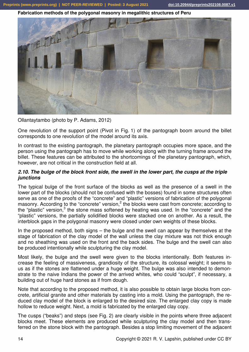
Ollantaytambo (photo by B. Foerster, 2009)
Preprints (www.preprints.org) | NOT PEER-REVIEWED | Posted: 3 August 2021 doi:10.20944/preprints202108.0087.v1
Fabrication methods of the polygonal masonry in megalithic structures of Peru
Copyright © 2021 R. V. Lapshin, published under CC BY 14
One revolution of the support point (Pivot in Fig. 1) of the pantograph boom around the billet corresponds to one revolution of the model around its axis.
In contrast to the existing pantograph, the planetary pantograph occupies more space, and the person using the pantograph has to move while working along with the turning frame around the billet. These features can be attributed to the shortcomings of the planetary pantograph, which, however, are not critical in the construction field at all.
2.10. The bulge of the block front side, the swell in the lower part, the cusps at the triple junctions
The typical bulge of the front surface of the blocks as well as the presence of a swell in the lower part of the blocks (should not be confused with the bosses) found in some structures often serve as one of the proofs of the “concrete” and “plastic” versions of fabrication of the polygonal masonry. According to the “concrete” version,2 the blocks were cast from concrete; according to the “plastic” version,3 the stone mass softened by heating was used. In the “concrete” and the “plastic” versions, the partially solidified blocks were stacked one on another. As a result, the interblock gaps in the polygonal masonry were closed under own weights of these blocks.
In the proposed method, both signs – the bulge and the swell can appear by themselves at the stage of fabrication of the clay model of the wall unless the clay mixture was not thick enough and no sheathing was used on the front and the back sides. The bulge and the swell can also be produced intentionally while sculpturing the clay model.
Most likely, the bulge and the swell were given to the blocks intentionally. Both features in-crease the feeling of massiveness, grandiosity of the structure, its colossal weight; it seems to us as if the stones are flattened under a huge weight. The bulge was also intended to demon-strate to the naive Indians the power of the arrived whites, who could “sculpt”, if necessary, a building out of huge hard stones as if from dough.
Note that according to the proposed method, it is also possible to obtain large blocks from con-crete, artificial granite and other materials by casting into a mold. Using the pantograph, the re-duced clay model of the block is enlarged to the desired size. The enlarged clay copy is made hollow to reduce weight. Next, a mold is fabricated by the enlarged clay copy.
The cusps (“beaks”) and steps (see Fig. 2) are clearly visible in the points where three adjacent blocks meet. These elements are produced while sculpturing the clay model and then trans-ferred on the stone block with the pantograph. Besides a stop limiting movement of the adjacent
Ollantaytambo (photo by P. Adams, 2012)
Preprints (www.preprints.org) | NOT PEER-REVIEWED | Posted: 3 August 2021 doi:10.20944/preprints202108.0087.v1

R. V. Lapshin
Copyright © 2021 R. V. Lapshin, published under CC BY 15
block in the horizontal plane, the cusps give the polygonal masonry a special grace. According to the creators’ idea, the cusps along with the parallelism of the smoothly changing curved edges were intended to give a sense of easiness of working with a stone. These features make the viewer think that the blocks are literally sculpted of a stone. And we must pay a tribute to the old masters; they succeeded in this technique!
Given the above, instead of the term “polygonal masonry”, it would be quite fair to use the term “polygonal sculpture” in the cases when a stone structure is created on the basis of hand-sculpting of a clay model made in a certain artistic style with unique lock interfaces between blocks.
Fig. 2. Cusps and steps
Preprints (www.preprints.org) | NOT PEER-REVIEWED | Posted: 3 August 2021 doi:10.20944/preprints202108.0087.v1
Fabrication methods of the polygonal masonry in megalithic structures of Peru
Copyright © 2021 R. V. Lapshin, published under CC BY 16
2.11. Indirect dating by the observed destructions of the masonry elements
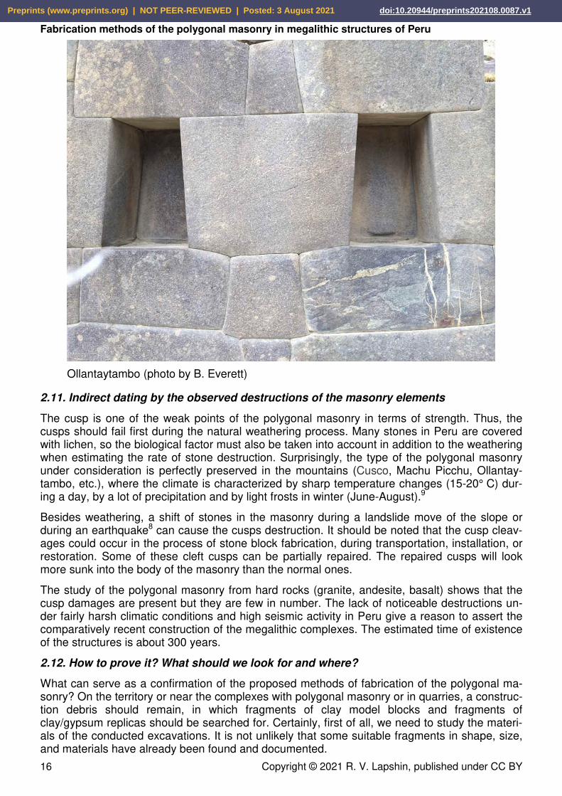
The cusp is one of the weak points of the polygonal masonry in terms of strength. Thus, the cusps should fail first during the natural weathering process. Many stones in Peru are covered with lichen, so the biological factor must also be taken into account in addition to the weathering when estimating the rate of stone destruction. Surprisingly, the type of the polygonal masonry under consideration is perfectly preserved in the mountains (Cusco, Machu Picchu, Ollantay-tambo, etc.), where the climate is characterized by sharp temperature changes (15-20° C) dur-ing a day, by a lot of precipitation and by light frosts in winter (June-August).9
Besides weathering, a shift of stones in the masonry during a landslide move of the slope or during an earthquake8 can cause the cusps destruction. It should be noted that the cusp cleav-ages could occur in the process of stone block fabrication, during transportation, installation, or restoration. Some of these cleft cusps can be partially repaired. The repaired cusps will look more sunk into the body of the masonry than the normal ones.
The study of the polygonal masonry from hard rocks (granite, andesite, basalt) shows that the cusp damages are present but they are few in number. The lack of noticeable destructions un-der fairly harsh climatic conditions and high seismic activity in Peru give a reason to assert the comparatively recent construction of the megalithic complexes. The estimated time of existence of the structures is about 300 years.
2.12. How to prove it? What should we look for and where?
What can serve as a confirmation of the proposed methods of fabrication of the polygonal ma-sonry? On the territory or near the complexes with polygonal masonry or in quarries, a construc-tion debris should remain, in which fragments of clay model blocks and fragments of clay/gypsum replicas should be searched for. Certainly, first of all, we need to study the materi-als of the conducted excavations. It is not unlikely that some suitable fragments in shape, size, and materials have already been found and documented.
Ollantaytambo (photo by B. Everett)
Preprints (www.preprints.org) | NOT PEER-REVIEWED | Posted: 3 August 2021 doi:10.20944/preprints202108.0087.v1

R. V. Lapshin
Copyright © 2021 R. V. Lapshin, published under CC BY 17
Assuming that in the pantograph used by the builders, the clay model and the stone billet were positioned in the same way as in the modern pantograph, i. e., horizontally with the backside down, then the chisel marks on the side surface of the stone blocks should go from right to left (chisel in the left hand, hammer in the right) and from top to bottom (at the beginning of the trace, the recess is larger than at the end). The marks themselves should be short parallel strokes arranged in vertical columns.
The chisel marks should be searched for on the stone blocks from hard rocks – granite, ande-site, basalt. Soft rocks, such as limestone, have a high porosity; the surface layer of these stones is quickly destroyed by weathering. Moreover, the chisel marks on the limestone surface are easily smoothed out during the subsequent tapping operation. Because of weathering, there is also no sense to study the interface surfaces of the stone blocks from hard rocks that have lain in the open air outside masonry for an unknown number of years. To analyze an interface surface, one should take stones from some untouched masonry having minimal gaps, which could get a very small amount of moisture.
2.13. Dating
If we accept the pantograph version, the structures of the “incredibly” ancient Incas can be dated by the years of invention/building of pantographs by Europeans. The pantograph for working with a flat drawing has been known since 1603.5 Records concerning the pantograph for working with three-dimensional objects appear somewhere in the second half of the 18th century.5 It should be noted that masters did not hurry to disclose their professional secrets in those days. Therefore, a description of the 3D-pantograph and the methods of working with it could appear in open publications decades after its invention and active use. Judging by how long the mystery of the polygonal masonry creation had been lasted, the master-masons were able to keep their secrets.
Ollantaytambo (photo by A. Fuchs, 2008)
Preprints (www.preprints.org) | NOT PEER-REVIEWED | Posted: 3 August 2021 doi:10.20944/preprints202108.0087.v1

Fabrication methods of the polygonal masonry in megalithic structures of Peru
Copyright © 2021 R. V. Lapshin, published under CC BY 18
2.14. Who built this, when and with what funds?
The problem with the structures based on the polygonal masonry is as follows. The official his-tory states that the structures had existed before the arrival of Europeans in the New World in the 16th century, and the American Indians did not know neither iron tools nor a wheel and did not have draft animals at that time. From this statement, there is only one conclusion: the struc-tures were built by some older civilization that existed in America before the Indians, meanwhile whose culture of stone working, in general, corresponded to the European construction culture of the 16-17th centuries.
The problem with this mythical older civilization is that it left behind no other material evidences of its existence, except for the perfect stone structures. As rightly noted in work 4, the high-quality polygonal masonry and the structures based on it appear instantly (by historical stan-dards) as if from nowhere, and then disappear also instantly into nowhere. There are neither previous nor subsequent noticeable development in the architecture and technology of the structures. But this may happen only when a group of professional builders comes to a certain territory for a short period, say, for 10 years, with their own tools, contrivances and construction techniques.
Transience of the events taken place in the construction industry of those years indicates the high productivity of the strange builders and their construction methods. The contradictions are instantly resolved if the authors of the structures are visiting European builders,10, 11, 12 and the time of erection of the structures is transferred from minus infinity to the 17-18th century. For delivery, moving, and rough processing of the stones, slope strengthening, and other heavy and unskilled work, of course, the local Indian people were driven together by orders of the Indian chiefs subdued/bought by the Spaniards. Thus, in a certain sense, the Peruvian megalithic complexes are the structures built by the Incas too, although not so ancient.
Any large-scale construction is always based on some strong economic foundation. It is difficult to imagine that the megalithic complexes were built for the Indians at the expense of the Span-iards. Of course, these complexes were created at the expense of the Indians and on bones of the Indians. But what could the Indians offer to the Spanish colonizers? The gold and silver that
Ollantaytambo (photo by I. Otkalo, 2015)
Preprints (www.preprints.org) | NOT PEER-REVIEWED | Posted: 3 August 2021 doi:10.20944/preprints202108.0087.v1
R. V. Lapshin
Copyright © 2021 R. V. Lapshin, published under CC BY 19
the Indians had was captured in the early years of the conquest and taken to Europe. The Pe-ruvian land was not able to produce much cotton, sugar cane, or grain.
Since the Indians had gold and silver at the beginning of the conquest, it means they took it somewhere. Therefore, the Spaniards organized gold and silver extraction in mines and gold-fields. And to make the work in the mines more fun, the aboriginal priesthood inspired the Indi-ans with the appearance and grandiosity of the megalithic temples, which were built at the ex-pense of part of the funds received from the extraction of the precious metals. After a few dec-ades, the easily accessible gold and silver deposits were exhausted, and the construction of the megalithic complexes has stopped. By this time, the power of the Spaniards and the Catholic Church had increased somehow imperceptibly, and the number of the Indians was greatly re-duced in some “incomprehensible” way.
Whether the miners ate poorly, or whether living in shacks did not add them a health, or whether the places of “strength” did not longer compensate for the strength taken away by the exhausting work in the mines, the history is silent. In general, the time came when the aban-doned religious structures of the Indians could be put in a good use without much trouble. And these structures have been put in a good use. Stone blocks and parts of the structures were used for erection of Catholic cathedrals, abbeys, palaces, villas, and city buildings.
3. Discussion
Among the video materials related to the topic, the work 3 should be noted. The author sug-gested using a reduced gypsum model of a stone block; and transferring and scaling of a com-plicated surface geometry perform with a caliper by several reference points. The gypsum model is usually required to avoid wearing of the original clay model (which is a work of art) while producing copies. This problem does not arise while fabricating blocks for the polygonal masonry. Moreover, in case of block model fabrication by a stone billet of arbitrary shape, the clay model is used just once and then thrown out (serves as a core for a new model). Thus, in order to reach the required result, possessing only a clay model of the block is quite enough.
The process of transferring a complicated surface geometry and its scaling by few reference points using a caliper is very time-consuming and inaccurate. However, this process ceases to be time-consuming and inaccurate if we apply a pantograph instead of the caliper. Analysis shows that in most cases, first, a clay model is created by a stone billet of an arbitrary shape using a pantograph. Then, the regions are cut out in the clay model of the block for interfacing with neighboring blocks. After that, a model wall is assembled of the model blocks. After drying, the wall is disassembled, and the interface sites of the model blocks are transferred to their stone billets by means of the pantograph.
Since there are no universal solutions in construction, as in any other field, the builders, besides pantograph, used other techniques based on application of the replicas. For example, the repli-cas were used in the sites where the stone structures of large blocks were abutted upon rocks. The replica was taken from a rock section and then applied to the processing stone block or, vice versa, the replica was taken from a stone block and then applied to the processing rock. Everything was depended on what was more convenient in each particular case. Since very large stone blocks are like rocks – they being extremely difficult to move, the replicas were also used for joining large blocks to very large blocks and very large blocks to other very large blocks.
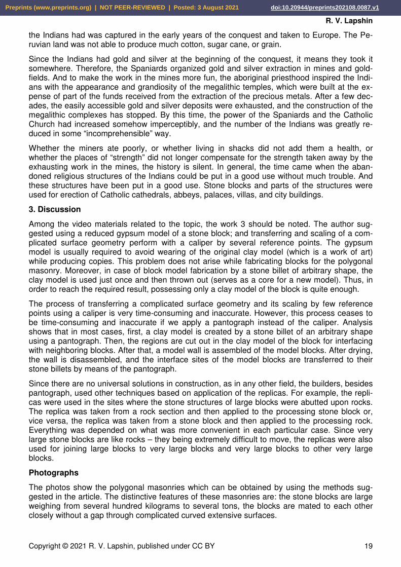
Photographs
The photos show the polygonal masonries which can be obtained by using the methods sug-gested in the article. The distinctive features of these masonries are: the stone blocks are large weighing from several hundred kilograms to several tons, the blocks are mated to each other closely without a gap through complicated curved extensive surfaces.
Preprints (www.preprints.org) | NOT PEER-REVIEWED | Posted: 3 August 2021 doi:10.20944/preprints202108.0087.v1

Fabrication methods of the polygonal masonry in megalithic structures of Peru
Copyright © 2021 R. V. Lapshin, published under CC BY 20
Acknowledgments
I thank O. V. Obyedkov, Prof. I. K. Fomenko, and O. E. Lyapin for critical reading of the mate-rial.
Used materials 1. J.-P. Protzen, “Inca quarrying and stonecutting”, Journal of the Society of Architectural Historians, vol. 44, no. 2, pp. 161-182, 1985. 2. Alexander, “Polygonal masonry: cottage technologies”, YouTube, 2015 (in Russian). 3. Unraveling History, “How was the polygonal masonry made?”, YouTube, 2019 (in Russian). 4. GRESAR, “Traces of somebody else's technologies”, parts 1-8, YouTube, 2019-2021 (in Russian). 5. Pantograph, Wikipedia. 6. M. Rogińska-Niesłuchowska, “The pantograph and its geometric transformations – a former popular tool for copying and scaling”, The Journal of Polish Society for Geometry and Engineering Graphics, volume 29, pages 59-65, 2016. 7. Michael Keropian, “3D Pantograph Enlarging”, parts 1-7, YouTube, 2018. 8. List of earthquakes in Peru, Wikipedia. 9. Climate of Peru, Wikipedia. 10. Alexander Tamanskiy, “Who and when did build the Egyptian pyramids?”, YouTube, 2020 (in Russian). 11. Alexander Tamanskiy, “How were the Egyptian pyramids built?”, YouTube, 2021 (in Russian). 12. Alexander Tamanskiy, “Who did build the American pyramids?”, YouTube, 2021 (in Russian).
Preprints (www.preprints.org) | NOT PEER-REVIEWED | Posted: 3 August 2021 doi:10.20944/preprints202108.0087.v1