fabrication of hybrid electric chopper type …umpir.ump.edu.my/8430/1/cd7971_@_35.pdf · pertama,...
TRANSCRIPT
FABRICATION OF HYBRID ELECTRIC CHOPPER TYPE MOTORCYCLE
FRONT SUSPENSION
MUHAMMAD AMIR AKMAL BIN AHAMAD KHALID
Report submitted in partial fulfilment of the requirements for the award of Diploma in
Mechanical Engineering
Faculty of Mechanical Engineering
UNIVERSITI MALAYSIA PAHANG
JULY 2013
iv
ABSTRACT
This thesis discussed the process of fabricating of hybrid electric chopper type
motorcycle front suspension system. Firstly, the current chopper type motorcycle and
hybrid system are studied. The studies include the design, advantages, disadvantages,
material and installation. Later, the concept is selected for further studies which
involving three dimensional modeling by using software SolidWorks. The fabrication of
this hybrid electric chopper type motorcycle front suspension system is later do because
the chassis first. The found out of problems also included. The problems covered from
the start till project ends. Lastly, the conclusion of the project is documented and given
some recommendation for further studies on the project.

v
ABSTRAK
Tesis ini membincangkan proses reka hibrid elektrik helikopter jenis motosikal sistem
suspensi hadapan. Pertama, semasa helikopter jenis motosikal dan sistem hibrid dikaji.
Kajian termasuk reka bentuk, kelebihan, kekurangan, bahan dan pemasangan.
Kemudian, konsep yang dipilih untuk melanjutkan pelajaran yang melibatkan tiga
model dimensi dengan menggunakan perisian SolidWorks. Fabrikasi hibrid elektrik
helikopter jenis motosikal sistem suspensi hadapan ini kemudian dilakukan kerana casis
pertama. Mendapati daripada masalah juga dimasukkan. Masalah-masalah yang
dibincangkan dari awal hingga akhir projek. Akhir sekali, kesimpulan projek
didokumenkan dan diberikan beberapa cadangan untuk kajian lanjut mengenai projek
itu.
vi
TABLE OF CONTENTS
Pages
SUPERVISOR’S DECLARATION ii
STUDENT’S DECLARATION iii
ACKNOWLEDGEMENTS iv
ABSTRACT v
ABSTRAK vi
TABLE OF CONTENTS vii
LIST OF TABLES ix
LIST OF FIGURES x
CHAPTER 1 INTRODUCTION
1.1 Project Background 1
1.2 Objective 3
1.3 Scope of Work 4
1.4 Problem Statement 4
1.5 Flow Chart 4
1.6 Gantt Chart 5
CHAPTER 2 LITERATURE REVIEW
2.1 Suspension system 6
2.2 Front suspension 6
2.3 Chopper type Motorcycle 8
2.4 Hybrid Electric Motorcycle 9
2.5 Bearing 11
vii
CHAPTER 3 METHODOLOGY
3.1 Reverse Engineering 14
3.2 Design and Planning 16
3.3 Material and Tools Preparation 19
3.4 Jig Fabrication Process 21
3.5 Servicing /Overhauling Front Suspension 25
CHAPTER 4 RESULTS AND DISCUSSIONS
4.1 Results 29
4.2 Discussions 32
CHAPTER 5 CONCLUSION AND RECOMMNEDATIONS
5.1 Conclusion 33
5.2 Recommendations 33
REFERENCES 34
APPENDICES
A Gantt Chart 35
viii
LIST OF TABLES
Tables No Title Pages
2.1 The comparison of front suspension 8
2.2 Differences of hybrid electric motorcycle than fuel 10
ix
LIST OF FIGURES
Figures No Title Pages
1.0 Chopper motorcycle 2
1.1 Springer front suspension 2
1.2 Telescopic front suspension 3
1.3 Flow Chart 5
2.1 CAD model of front motorbike suspension 7
2.2 Chopper motorcycle 9
2.3 Electric Chopper motorcycle 10
2.4 Electric engine 11
2.5 Tapered roller bearing 12
2.6 Needle roller bearing 13
3.1 Modenas Jaguh front suspension 15
3.2 New part after machining 15
3.3 Ball bearing 16
3.4 New upper part of the fork 17
3.5 Side view of front suspension in 3D 17
3.6 Front view of front suspension in 3D 18
3.7 Integrating the front suspension into hybrid electric Chopper 19
3.8 Front suspension unit hold at rake 50 degree angle 20
3.9 MIG welding machine 20
3.10 Tire holder 21
3.11 Measure the height for motorcycle 21
3.12 Build the permanent front tire holder at the jig 22
3.13 Leveling is used 23
3.14 Measure the height of tire holder 23
3.15 A jig for front suspension 50 degree slanted 24

x
3.16 50 degree of slanted front suspension unit 24
3.17 Loosed and remove the part 25
3.18 Remove the fork oil and spring 26
3.19 Use Allen Wrench to remove damper rod bolt 27
3.20 Internal part of fork tubes 27
3.21 Peel the O-ring from the fork tube 28
4.1 The different of length of upper part 30
4.2 Tapered roller bearing 30
4.3 A jig 50 degree slanted 31
4.4 Front suspension after servicing 32
CHAPTER 1
INTRODUCTION
1.1 PROJECT BACKGROUND
The suspension system allows relative motion in the vehicle and provides
comfort and smoothness for the rider. The suspension also helps to support the
vehicle weight, keeping the vehicle tires in contact with the road and maintaining
the correct vehicle ride height. Suspension system consists of springs, shock
absorbers and linkages that connects a vehicle to its wheels and allows relative
motion between the two.
For instant, front suspension in a motorcycle consists of spring, absorber and
linkage helped in handling the vehicle, supporting the loads and provide user
comfort. There are various types of front suspension available in the market, these
include telescopic, trailing tube, leading link, springer, earles, girder, telelever,
duolever, coaxial steering front suspension, non-fork and triple tree. The numerous
types of front suspensions provide different characters to suit the motorcycle design.
The front suspension is selected by refer to the objective of the build of motorcycle
(Wilson and Hugo, 1995).
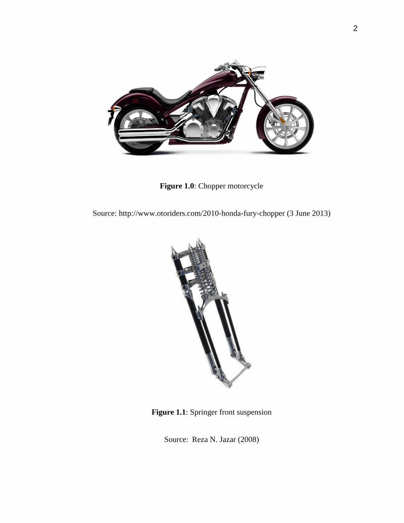
2
Figure 1.0: Chopper motorcycle
Source: http://www.otoriders.com/2010-honda-fury-chopper (3 June 2013)
Figure 1.1: Springer front suspension
Source: Reza N. Jazar (2008)
3
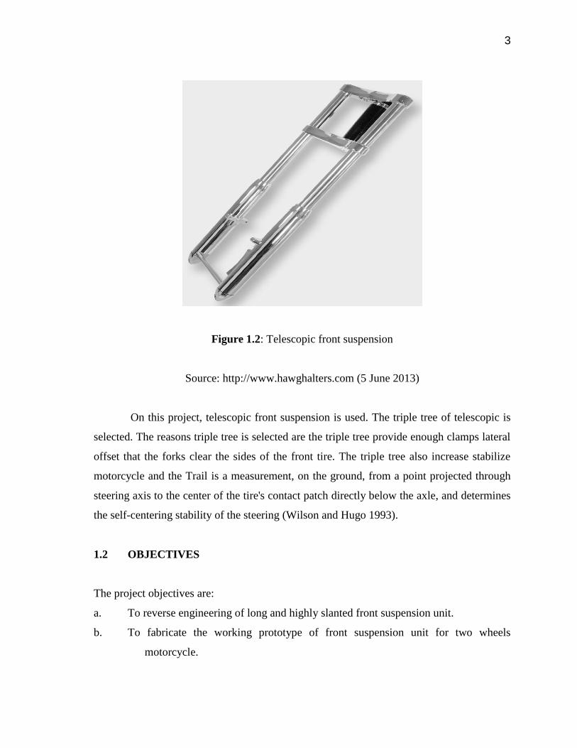
Figure 1.2: Telescopic front suspension
Source: http://www.hawghalters.com (5 June 2013)
On this project, telescopic front suspension is used. The triple tree of telescopic is
selected. The reasons triple tree is selected are the triple tree provide enough clamps lateral
offset that the forks clear the sides of the front tire. The triple tree also increase stabilize
motorcycle and the Trail is a measurement, on the ground, from a point projected through
steering axis to the center of the tire's contact patch directly below the axle, and determines
the self-centering stability of the steering (Wilson and Hugo 1993).
1.2 OBJECTIVES
The project objectives are:
a. To reverse engineering of long and highly slanted front suspension unit.
b. To fabricate the working prototype of front suspension unit for two wheels
motorcycle.

4
1.3 SCOPES OF WORK
The scopes that will be figure out in this project are :
a. Reverse engineering.
b. Design in 3D modeling.
c. Machining required part (Absorber part).
d. Fabrication prototype based on the refined design.
e. Servicing fork.
f. System intergration and operation verification.
g. Final report prepared
1.4 PROBLEM STATEMENT
Fabrication of a long and highly slanted front suspension unit for a hybrid electric
Chopper type motorcycle can be done by refer to the current chopper rake angle through
reverse engineering. However, it is impossible to get the prototype exactly same long and
highly slanted as design. Therefore it is necessary to solve the problems in fabrication to
ensure the fabricated prototype is functional and provide comfort to the riders.
1.5 FLOW CHART
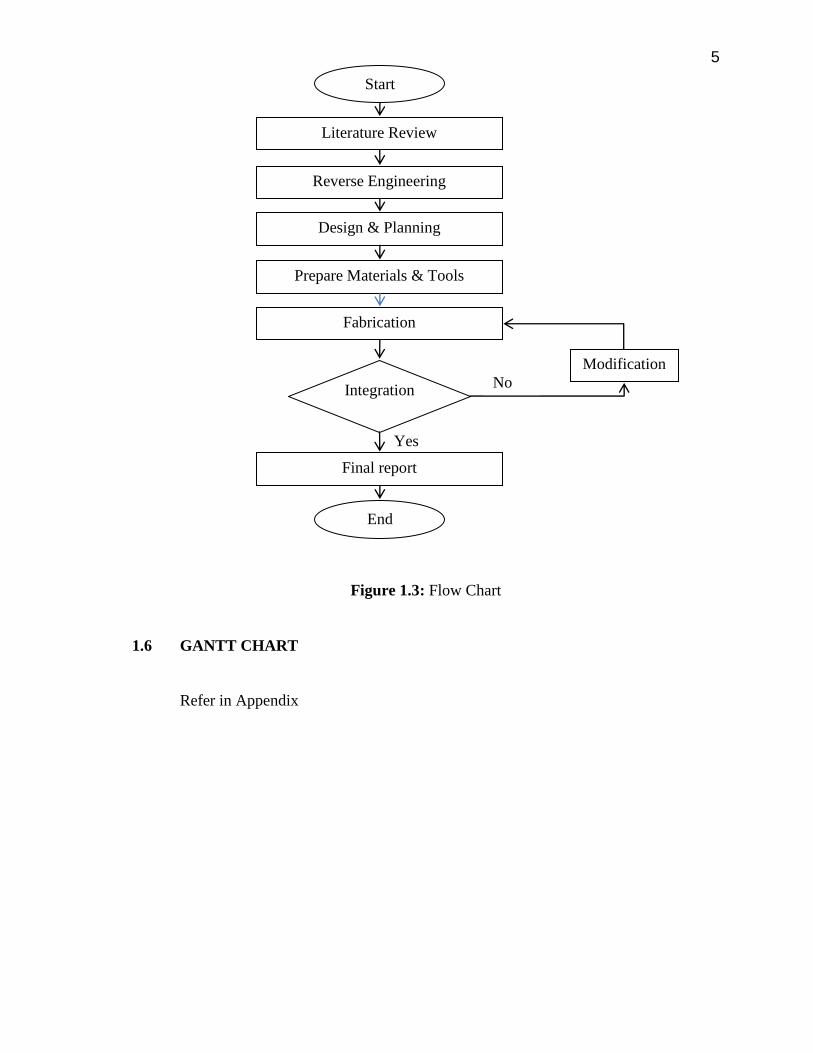
Figure 1.3 illustrate the project flow chart
5
Figure 1.3: Flow Chart
1.6 GANTT CHART
Refer in Appendix
Yes
Start
Literature Review
Integration
Final report
Design & Planning
Reverse Engineering
Prepare Materials & Tools
Fabrication
Modification
No
End
CHAPTER 2
LITERATURE REVIEW
2.1 SUSPENSION SYSTEM
Suspension is the term given to the system of spring, shock absorber and linkages
that connect a vehicle to its wheels and allows relative motion between two whether move
forward or backwards (Wilson and Hugo, 1995). Suspension system is important to insulate
the weight of rider and motorcycle also the shock from the road. The suspension system
also important to keep the wheels contact with the ground for maximum control, steering
and holding. Suspension has two types which is Front suspension and Rear suspension.
Front suspension is the suspension that located in front of the system while rear suspension
is vice versa to the front suspension. The typical motorcycle has a pair of fork tubes for the
front suspension, and a swing arm with one or two shock absorbers for the rear suspension.
2.2 FRONT SUSPENSION
The main structure of front suspensions is made up of components joined each other
by shaft-hub coupling.
7
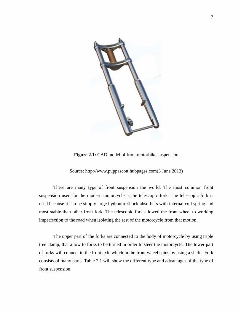
Figure 2.1: CAD model of front motorbike suspension
Source: http://www.puppascott.hubpages.com(3 June 2013)
There are many type of front suspension the world. The most common front
suspension used for the modern motorcycle is the telescopic fork. The telescopic fork is
used because it can be simply large hydraulic shock absorbers with internal coil spring and
most stable than other front fork. The telescopic fork allowed the front wheel to working
imperfection to the road when isolating the rest of the motorcycle from that motion.
The upper part of the forks are connected to the body of motorcycle by using triple
tree clamp, that allow to forks to be turned in order to steer the motorcycle. The lower part
of forks will connect to the front axle which in the front wheel spins by using a shaft. Fork
consists of many parts. Table 2.1 will show the different type and advantages of the type of
front suspension.
8
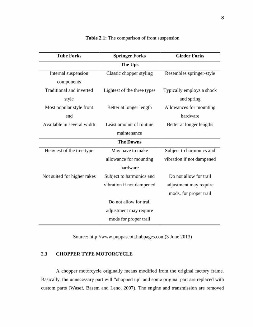
Table 2.1: The comparison of front suspension
Tube Forks Springer Forks Girder Forks
The Ups
Internal suspension
components
Classic chopper styling Resembles springer-style
Traditional and inverted
style
Lightest of the three types Typically employs a shock
and spring
Most popular style front
end
Better at longer length Allowances for mounting
hardware
Available in several width Least amount of routine
maintenance
Better at longer lengths
The Downs
Heaviest of the tree type May have to make
allowance for mounting
hardware
Subject to harmonics and
vibration if not dampened
Not suited for higher rakes Subject to harmonics and
vibration if not dampened
Do not allow for trail
adjustment may require
mods, for proper trail
Do not allow for trail
adjustment may require
mods for proper trail
Source: http://www.puppascott.hubpages.com(3 June 2013)
2.3 CHOPPER TYPE MOTORCYCLE
A chopper motorcycle originally means modified from the original factory frame.
Basically, the unnecessary part will “chopped up” and some original part are replaced with
custom parts (Wasef, Basem and Leno, 2007). The engine and transmission are removed

9
and the factory frame it cut and welded back together to make it lower and lighter. Some
modification was made to the certain part like chroming the fork, and custom paint designs.
The overall look and performance make chopper different from factory motorcycle. The
chopper motorcycle is suitable for hybrid because chopper motorcycle has a big space for
insert the engine, drive train and electric engine. Chopper motorcycle also can carry a
weight because it is consider a torque of the chopper motorcycle is high (Frank and Wong,
2001).
Figure 2.2: Chopper Motorcycle
Source: http://www.clarkdever.com(4 June 2013)
2.4 HYBRID ELECTRIC MOTORCYCLE
A hybrid electric motorcycle thrusts with two or more energy sources and at least
one of them deliver electrical energy. The electric system in hybrid electric motorcycle
operates at high efficiency, allow diversification of energy resources, zero local emission
and work silently (Chau and Wong, 2002). The hybrid electric motorcycle had many
advantages than fuel motorcycle. In price factor the hybrid electric motorcycle more costly
10
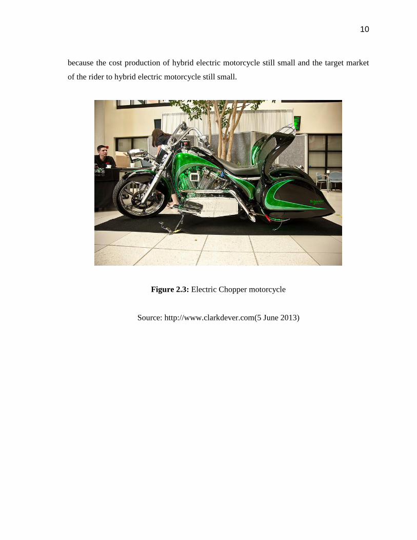
because the cost production of hybrid electric motorcycle still small and the target market
of the rider to hybrid electric motorcycle still small.
Figure 2.3: Electric Chopper motorcycle
Source: http://www.clarkdever.com(5 June 2013)
11
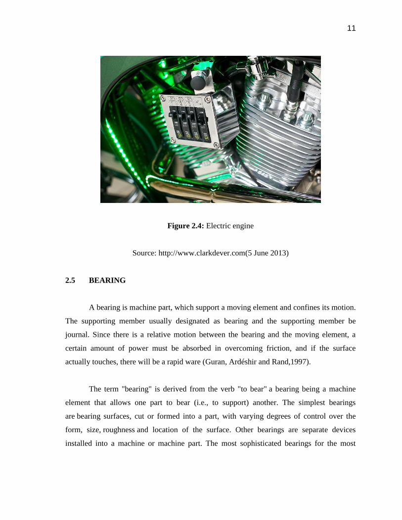
Figure 2.4: Electric engine
Source: http://www.clarkdever.com(5 June 2013)
2.5 BEARING
A bearing is machine part, which support a moving element and confines its motion.
The supporting member usually designated as bearing and the supporting member be
journal. Since there is a relative motion between the bearing and the moving element, a
certain amount of power must be absorbed in overcoming friction, and if the surface
actually touches, there will be a rapid ware (Guran, Ardéshir and Rand,1997).
The term "bearing" is derived from the verb "to bear" a bearing being a machine
element that allows one part to bear (i.e., to support) another. The simplest bearings
are bearing surfaces, cut or formed into a part, with varying degrees of control over the
form, size, roughness and location of the surface. Other bearings are separate devices
installed into a machine or machine part. The most sophisticated bearings for the most

12
demanding applications are very precise devices; their manufacture requires some of the
highest standards of current technology (Merriam-Webster, Inc. 1964).
The main function of a rotating shaft is to transmit power form one end of the line
to the other. The bearing also ensure stability and frictionless rotation (Purtell and John,
1999/2001).
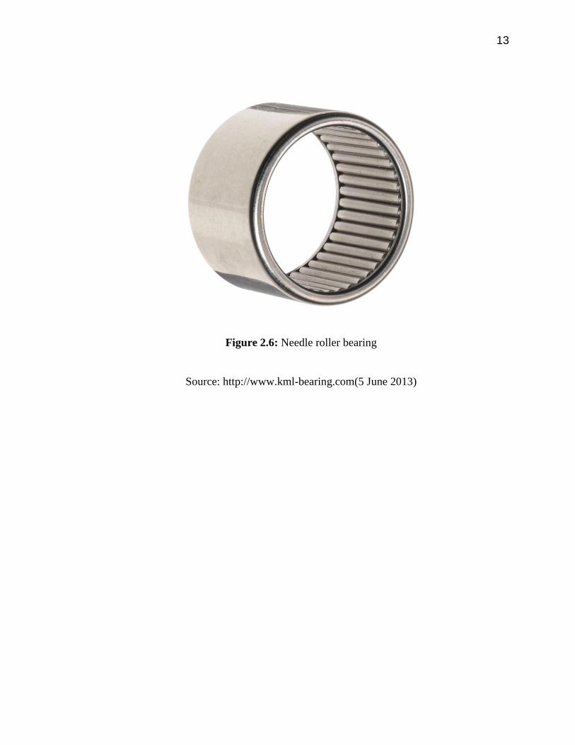
For instants, there is many type of bearing in the market. The common bearing is
tapered roller bearing and deep groove ball bearing. The needed of bearing depend on the
purpose. There are various types of bearing available in the market, these include journal
bearing, solid bearing, bushed bearing, pedestal bearing, thrust bearing, footstep bearing,
collar bearing, rolling contact bearing, spherical roller bearing, cylindrical roller bearing
and tapered roller bearing. Figure 2.5 will show the tapered roller bearing and Figure 2.6
will show needle roller bearing.
Figure 2.5: Tapered roller bearing
Source: http://www.kml-bearing.com(5 June 2013)
13
Figure 2.6: Needle roller bearing
Source: http://www.kml-bearing.com(5 June 2013)
CHAPTER 3
METHODOLOGY
3.1 REVERSE ENGINEERING
A front suspension or fork in motorcycle Modenas Jaguh, Figure 3.1 will show the
Modenas Jaguh front suspension is dismantled for reverse engineering purpose. In order to
reduce the time frame and cost, the fork will be modified and reuse in the hybrid electric
Chopper, however the existing fork is not long enough to produce a long and high slanted
front suspension unit, therefore the upper part of the fork is replace by a new machining
part. Figure 3.2 show the new part after machining.
The new part used stainless steel 304 to provide the require strength and corrode
resistance. On the other hand, the ball bearing is replace by tapered roller bearing. The
tapered roller bearing is easier to handle and service. Figure 3.3 shows the ball bearing.

15
Figure 3.1 : Modenas Jaguh front suspension
Figure 3.2 : New part after machining

16
Figure 3.3 : Ball bearing
3.2 DESIGN AND PLANNING
The front suspension components 3D models are build in CAD software
SolidWork. Then, the models are integrated into the hybrid electric chopper chassis. Figure
3.4 presents the 3D model for the new upper part of the fork which require machining.