facility accessibility design manual - city of...
TRANSCRIPT

City of Guelph
2015 Facility
Accessibility Design Manual

C i t y o f G u e l p h - 2 0 1 5 F a c i l i t y A c c e s s i b i l i t y D e s i g n M a n u a l
ACKNOWLEDGEMENTS
i
June 2015
Re: City of Guelph - Facility Accessibility Design Manual
Dear reader/user of this manual,
On behalf of the City of Guelph we are pleased to be able to present to you our 2015 Facility Accessibility Design Manual. These standards apply to all newly constructed and/or renovated facilities, owned, leased or operated by the City of Guelph. We would like to thank and recognize the contributions of:
• The City of London - for its generous permission to use the City of London Facility Accessibility Design Standards as a template for this document.
• The many community participants from the City of London who attended focus-group sessions and took the time to review and provide invaluable input into the parent document - the City of London’s Facility Accessibility Design Standards.
2007 Facility Accessibility Design Standards for the City of London
Accessibility Guidelines for the City of Toronto
Accessibility Guidelines for Buildings and Facilities (ADAAG) - The American with Disabilities Act
Barrier-Free Design - CAN/CSA-B651
Barrier-Free Design Guidelines - Alberta Safety Codes Council
Barrier-Free Design Guidelines - City of North York
The Ontario Building Code
Barrier-Free Design Standards - Regional Municipality of Hamilton -Wentworth and the Corporation of the City of Hamilton
Joint Municipal Guidelines for Accessibility for the Towns of Richmond Hill, Markham and Vaughan
• Mr. Bob Topping and other staff of DesignABLE Environments Inc. (www.designable.net), who have been instrumental in creating the City of Guelph’s innovative and universally accessible Facility Accessibility Design Manual.
• Members of the City of Guelph Accessibility Advisory Committee and City Staff who have taken the time to provide DesignABLE Environments with their input concerning this design manual.
We would also like to acknowledge the following documents that were utilized to develop the City of Guelph’s Facility Accessibility Design Manual:In addition to our use of this manual for our own facilities, we encourage the use of the City of Guelph
Facility Accessibility Design Manual throughout the community and hope that you find them interesting and valuable for your facility construction and/or renovation projects.
This document available in alternate formats upon request to:Accessibility Services phone: 519-822-1260 ext. 2670 TTY: 519-826-9771 email: [email protected]

This page intentionally left
blank
ii

C i t y o f G u e l p h - 2 0 1 5 F a c i l i t y A c c e s s i b i l i t y D e s i g n M a n u a l
TABLE OF CONTENTS
T A B L E O F C O N T E N T S
1.0 Introduction ........................... 1
2.0 GlossaryandDefinitions ......... 2
3.0 Scope and Application ............ 7
4.0 Design Standards ................... 9
4.1 Access and Circulation4.1.1 Space and Reach Requirements ..114.1.2 Ground and Floor Surfaces .........134.1.3 Protruding & Overhead Objects ..144.1.4 Accessible Routes, Paths
And Corridors ...........................154.1.5 Entrances ................................174.1.6 Doors .....................................184.1.7 Gates, Turnstiles and Openings .................................224.1.8 Windows, Glazed Screens
and Sidelights ..........................234.1.9 Ramps ....................................244.1.10 Curb Ramps .............................274.1.11 Stairs ......................................294.1.12 Handrails .................................304.1.13 Escalators................................314.1.14 Elevators .................................324.1.15 Platform Lifts ...........................35
4.2 Washroom Facilities4.2.1 Toilet and Bathing Facilities ........364.2.2 Toilet Stalls ..............................384.2.3 Toilets .....................................404.2.4 Lavatories ...............................414.2.5 Urinals ....................................424.2.6 Washroom Accessories ..............434.2.7 Universal Washrooms ................444.2.8 Bathtubs .................................464.2.9 Shower Stalls ...........................474.2.10 Grab Bars ................................48
4.3 Other Amenities4.3.1 Drinking Fountains ....................494.3.2 Viewing Positions ......................504.3.3 Elevated Platforms ....................534.3.4 Dressing Rooms .......................544.3.5 Offices, Work Areas and
Meeting Rooms ........................554.3.6 Waiting and Queuing Areas ........564.3.7 Tables, Counters and Work Surfaces ..........................574.3.8 Information, Reception
and Service Counters ................584.3.9 Storage, Shelving and
Display Units............................594.3.10 Lockers and Baggage Storage ....604.3.11 Balconies, Porches, Terraces
And Patios ...............................614.3.12 Parking ...................................624.3.13 Passenger Loading Zones ...........65
4.3.14 Landscaping Materials and Plantings ...........................66
4.3.15 Benches ..................................674.3.16 Public Use Eating Areas .............684.3.17 Street Furniture .......................69
4.4 Systems and Controls4.4.1 Emergency Exits, Fire
Fire Evacuation and Areas of Refuge Assistance .................70
4.4.2 Controls and OperatingMechanisms .............................71
4.4.3 Vending and Ticketing Machines .................................724.4.4 Visual Alarms ...........................734.4.5 Public Telephones .....................744.4.6 Assistive Listening Systems .......764.4.7 Signage ..................................774.4.8 Detectable Warning Surfaces ......794.4.9 Public Address Systems .............804.4.10 Information Systems .................814.4.11 Card Access, Safety and
Security Systems......................824.4.12 Glare and Light Sources ............834.4.13 Lighting...................................844.4.14 Materials and Finishes ...............854.4.15 Texture and Colour ...................864.4.16 Acoustics .................................874.4.17 Pedestrian Signals ....................88
4.5 Facility-SpecificRequirements4.5.1 Arenas, Halls and Other
Indoor Recreational Facilities ......894.5.2 Outdoor Recreational Facilities ....904.5.3 Swimming Pools, Therapeutic Pools and Public Spas ................934.5.4 Cafeterias ................................954.5.5 Churches, Chapels and Other
Places of Worship .....................964.5.6 Libraries ..................................974.5.7 Business, Mercantile and Civic ....994.5.8 Police Stations .......................1004.5.9 Municipal Courts .....................1014.5.10 Transportation Facilities ...........1024.5.11 Public Housing .......................1034.5.12 Schools .................................1044.5.13 Public Historic Places ...............1074.5.14 Fire, EMS Offices and Work Areas ............................................108
5.0 Implementation and Enforcement ........................109
APPENDICES
A Universal Design Principles and Guidelines .......................111B Change Order Form ................112C FADM Design Checklist ............113D FADM Design Review Process ...120
iii

This page intentionally left
blank

C i t y o f G u e l p h - 2 0 1 5 F a c i l i t y A c c e s s i b i l i t y D e s i g n M a n u a l
1 . 0 I N T R O D U C T I O N
This manual addresses accessibility requirements for the design and construction of new facilities, as well as the retrofit, alteration or addition to existing facilities, owned, leased or operated by the City of Guelph. This design manual particularly addresses the needs of persons with disabilities, including, but not limited to, persons who are mobility impaired, hearing impaired, visually impaired or cognitively impaired, persons who are deaf-blind and persons with limited stamina and/or dexterity.
This design manual is intended to encompass the intent of the Ontario Human Rights Code, in terms of respecting the dignity of persons with disabilities. “The phrase ‘respects their dignity’ means to act in a manner which recognizes the privacy, confidentiality, comfort, autonomy and self-esteem of persons with disabilities, which maximizes their integration and which promotes full participation in society.” (Ontario Human Rights Commission)
This design manual incorporates the belief in universal design that recognizes the broad diversity of people who use facilities. Universal design is defined as:“The design of products and environments to be usable by all people, to the greatest extent possible, without the need for adaptation or specialized design.”The universal design philosophy is structured around the seven design principles listed below. (Refer to Appendix A for further information on the universal design principles and their guidelines.)
This design manual reflects minimum dimensional criteria required for adult persons. Prior to the design stage
of a project, special consideration should be given to the function of the facility and the patrons who will use it. A review and upgrade of the design standards presented in this manual may be required in some instances, particularly if a facility is designed primarily for the use of a particular type of user, such as children or older persons.
Where conflicts exist between scoping and/or dimensional requirements of this design manual and standards or legislation enacted by the federal or provincial governments, the most accommodating requirements shall apply (i.e. the requirement(s) that will result in the most accommodating environment, but never less than the minimum requirements of the current Ontario Building Code and Accessibility for Ontarians with Disabilities Act Regulations), provided federal or provincial approvals are obtained where required.
The City of Guelph shall review and/or update this design manual every 3-5 years, to reflect user feedback, technological advancement and new construction practices, as well as changes to the barrier-free design requirements of various codes and standards such as the Ontario Building Code and the CSA Standard B651 - Accessible Design for the Built Environment.
This design manual recognizes the concept of equivalent facilitation as a means to encourage new and innovative design ideas and solutions. Departures from particular technical and scoping requirements of this manual through the use of other designs and technologies is encouraged,
when the alternatives will provide substantially equivalent or greater access to the usability of the element and/or facility. Design departures from information provided and referenced in this manual should be carefully assessed to determine if it maximizes integration and promotes full participation. The City of Guelph has developed a design review process which includes a committee to review and evaluate situations that are seemly technically infeasible.
The process is called the FADM Review and Alternative Design Review Process. This design aid is a companion document to the FADM and is applicable for the design and construction of City facilities as set out in the FADM. Refer to Appendix D for further information. A Design Checklist has been developed to assist staff, designers and contracted consultants with the application of the FADM to ensure that each element has been applied to each project, and to document elements of a project that may be technically infeasible to implement. Refer to Appendix C for further information.
Dimensions used in this manual are in metric units. Nearest imperial equivalent dimensions are in parentheses.
For the purposes of this design manual, words and terms in italics have their meanings defined in Section 2.0.
The City of Guelph encourages all users of this manual to provide feedback, as well as to make proposals for changes, additions and/or deletions. A proposed Change Order Form is included as Appendix B.
1. EQUITABLE USE: The design is useful and marketable to people with diverse abilities.
2. FLEXIBILITY IN USE:The design accommodates a wide range of individual preferences and abilities.
3. SIMPLE AND INTUITIVE USE Use of the design is easy to understand, regardless of the user’s experience, knowledge, language skills, or
current concentration level.4. PERCEPTIBLE INFORMATION:
The design communicates necessary information effectively to the user, regardless of ambient conditions or the user’s sensory abilities.
5. TOLERANCE FOR ERROR:The design minimizes hazards and the adverse consequences of accidental or unintended actions.
6. LOW PHYSICAL EFFORT:The design can be used efficiently and comfortably with a minimum of fatigue.
7. SIZE AND SPACE FOR APPROACH AND USE:Appropriate size and space are provided for approach, reach, manipulation and use, regardless of user’s
body position, size, posture or mobility.
The Principles of UNIVERSAL DESIGN
© NC State University, The Center for Universal Design 1
1.0 INTRODUCTION

C i t y o f G u e l p h - 2 0 1 5 F a c i l i t y A c c e s s i b i l i t y D e s i g n M a n u a l
2.0 GLOSSARY AND DEFINITIONS
GRAPHIC CONVENTIONS
Dimensions that are not marked maximum or minimum are absolute, unless otherwise indicated.
GENERAL TERMINOLOGY
comply with Meet one or more specifications of this manual.
if … then Denotes a specification that applies only when the conditions described are present.
may Denotes an option or alternative.
shall Denotes a mandatory specification or requirement.
should Denotes an advisory specification or recommendation.
DEFINITIONS
Access aisle: An accessible pedestrian space between elements, such as parking spaces, seating and desks, that provides clearances appropriate for the use of the elements.
Accessible: Describes a site, building, facility or portion thereof that complies with the requirements of this design manual.
Accessible element: An element specified by this manual (for example, telephone, controls etc.).
Accessible route: A continuous unobstructed path connecting accessible elements and spaces of a facility. Interior accessible routes may include corridors, floors, ramps, elevators, platform lifts and clear floor spaces at fixtures. Exterior accessible routes may include parking access aisles, curb ramps, crosswalks at vehicular ways, walks, ramps and platform lifts.
Accessible space: Space that complies with the requirements of this design manual.
Adaptable: The ability of a certain building space or element, such as kitchen counters, sinks, and grab bars, to be added or altered so as to accommodate the needs of individuals with or without disabilities or to accommodate the needs of persons with different types or degrees of disabilities.
Addition: An expansion, extension, or increase in the gross floor area of a facility.
Alteration: A change to a facility that affects or could affect the usability of the facility or part thereof. Alterations include, but are not limited to, remodelling, renovation, retrofitting, rehabilitation, reconstruction, historic restoration, resurfacing of circulation paths or vehicular ways, changes or rearrangement of the structural parts or elements, and changes or rearrangement in the plan configuration of walls and full-height partitions. Normal maintenance, painting or wallpapering, or changes to mechanical or electrical systems are not alterations, unless they affect the usability of the building.
Amenities: Items that provide conveniences or services for use by the public, examples of which include drinking fountains, benches and garbage receptacles.
Area of refuge: An area which has direct access to an exit, where people who are unable to use stairs may remain temporarily in safety to await further instructions or assistance during emergency evacuation.
Assembly area: A room or space accommodating a group of individuals for recreational, educational, political, social, civic or amusement purposes, or for the consumption of food and drink.
Attic or Roof space: The space between the roof and the ceiling of the top storey or between a dwarf wall and a sloping roof.
Automatic door: A door equipped with a power-operated mechanism and controls that open and close the door automatically upon receipt of a momentary actuating signal. The switch that begins the automatic cycle may be a photoelectric device, floor mat, or manual switch. (See Power-assisted door)
Beach Access Routes: Routes that are constructed and are intended for pedestrian use by the public and that provide access from off-street parking facilities, recreational trails, exterior paths of travel and amenities to an area of a beach that is intended for recreational use by the public.
Bevel: A small slope that helps an individual negotiate an elevation change.
Board room or Conference room or Meeting room: Room used for meetings, which accommodates more than six people.
Building: A structure occupying an area greater than ten square metres, consisting of a wall, roof and floor or any of them, or a structural system serving the function thereof, including all plumbing, fixtures and service systems appurtenant thereto; or a structure occupying an area of ten square metres or less that contains plumbing, including the plumbing appurtenant thereto; or structures designated in the Ontario Building Code.
Circulation path: An exterior or interior way of passage from one place to another for pedestrians, including, but not limited to, walks, hallways, courtyards, stairways, and stair landings.
Clear: Unobstructed.
Clear floor space: The minimum unobstructed floor or ground space required to accommodate a single, stationary wheelchair, scooter or other mobility device, including the user.
2 2 . 0 G L O S S A R Y A N D D E F I N I T I O N S

C i t y o f G u e l p h - 2 0 1 5 F a c i l i t y A c c e s s i b i l i t y D e s i g n M a n u a l
2.0 GLOSSARY AND DEFINITIONS
Closed-circuit telephone: A telephone with dedicated line(s), such as a house phone, courtesy phone or phone that must be used to gain entrance to a facility.
Common use: Refers to those interior and exterior rooms, spaces or elements that are made available for the use of a restricted group of people (for example, occupants of a homeless shelter, the occupants of an office building, or the guests of such occupants).
Cross slope: The slope that is perpendicular to the direction of travel. (See running slope)
Curb ramp: A short ramp cutting through a curb or built up to a curb.
Depressed curb: A continuous area where a curb is lowered to the same level as the adjacent roadway, resulting in a seamless transition between a pedestrian walkway and a vehicular route.
Detectable warning: A standardized surface feature built into or applied to walking surfaces or other elements to warn persons with a visual impairment of hazards on a circulation path.
Disability: Any restriction or lack of ability to perform an activity in the manner or within the range considered normal for a human being.
Egress, Means of: A continuous and unobstructed way of exit travel from any point in a facility to a public way. A means of egress comprises vertical and horizontal travel and may include intervening room spaces, doorways, hallways, corridors, passageways, balconies, ramps, stairs, enclosures, lobbies, horizontal exits, courts and yards. An accessible means of egress is one that complies with the design requirements of this manual and does not include stairs, steps or escalators. Areas of refuge, protected lobbies or protected elevators may be included as part of an accessible means of egress.
Element: An architectural or mechanical component of a building, facility, space or site (e.g., telephone, curb ramp, door, drinking fountain, seating or water closet).
Entrance: Any access point into a building or a facility used for the purposes of entering. An entrance includes the approach walk, the vertical access leading to the entrance platform, the entrance platform itself, vestibules (if provided), the entry door(s) or gate(s), and the hardware of the entry door(s) or gate(s).
Environmental Mitigation: Activities that are intended to reduce, mitigate, prevent or compensate for adverse effects of human activities or items, including paths, play spaces, trails and parking, upon fish, wildlife, plants, invertebrates, species at risk, ecological integrity or natural heritage values.
Environmental Restoration: Activities that are intended to benefit fish, wildlife, plants, invertebrates, species at risk, ecological integrity or natural heritage values.
Facility or Facilities: All or any portion of buildings, structures, site improvements, complexes, equipment, roads, walks, passageways, parks, parking lots or other real or personal property located on a site.
Graspable: a shape that allows a user to firmly grip and pull at various angles. Graspable profiles allow fingers to wrap around as in a circular shape or have recesses below the widest part to allow for finger and thumb lands.
Ground floor: Any occupiable floor less than one storey above or below grade with direct access to grade. A facility always has at least one ground floor and may have more than one ground floor, as where a split-level entrance has been provided or where a facility is built into a hillside.
Guard: A safety railing used as a barrier to prevent encroachment or accidental falling from heights.
Handicap: A disadvantage for a given individual, resulting from an impairment or disability that limits or prevents the fulfillment of a role that is normal (depending on age, sex, social and cultural factors) for that individual. A handicap is an external factor which limits the full use of a facility/function for a specific individual.
Handrail: A component which is normally grasped by hand for support at stairways and other places where needed for safety of pedestrians.
Heritage Facility: A facility or portions thereof designated under the Ontario Heritage Act, or identified within the inventory of built heritage of a Heritage Committee within the City of Guelph.
Impairment: Any loss or abnormality of psychological, physiological or anatomical structure or function.
Maintenance: Activities that are intended to keep existing public spaces and elements in existing public spaces in good working order or to restore the spaces or elements to their original condition, examples of which include painting and minor repairs.
Mezzanine or Mezzanine floor: That portion of a storey which is an intermediate floor level, placed within the storey and having occupiable space above and below its floor.
Marked crossing: A crosswalk or other identified path intended for pedestrian use in crossing a vehicular way.
3 2 . 0 G L O S S A R Y A N D D E F I N I T I O N S

4
C i t y o f G u e l p h - F a c i l i t y A c c e s s i b i l i t y D e s i g n M a n u a l
Occupiable: A room or enclosed space designed for human occupancy in which individuals congregate for amusement, educational or similar purposes, or in which occupants are engaged at labour, and which is equipped with means of egress, light and ventilation.
Obligated Organization: These include the Government of Ontario, the Legislative Assembly, a designated public sector organization, a large organization and a small organization to which the standards in the AODA's Integrated Accessibility Standards Regulation apply.
Open space: Large-scale tracts of land without visible evidence of residential, commercial or industrial development. These areas may be privately or publicly owned and are generally left in a natural state and not programmed for active recreation. The benefits of open lands typically extend beyond the immediate area and usually provide community-wide benefits.
Operable portion: A part of a piece of equipment or appliance used to insert or withdraw objects, or to activate, deactivate, or adjust the equipment or appliance (for example, coin slot, push button, handle).
Park: Land that is privately or publicly held that has been developed for multiple recreational and leisure-time uses. This land benefits the entire community and balances the demands of the public for outdoor recreational facilities and other amenities, such as pathways, plazas, picnic areas, playgrounds, water features, play spaces for free play and leisure.
Power-assisted door: A door used for human passage that has a mechanism that helps to open the door or relieves the opening resistance of a door, upon the activation of a switch or a continued force applied to the door itself.
Private open space: Privately owned land areas within a subdivision, generally smaller in scale than open space, which have been left free from structures, parking lots and roads. These types of areas generally benefit only the residents or employees of the particular subdivision and usually remain in private ownership.
Public Heritage Facility: A facility or portions thereof designated under the Ontario Heritage Act, or identified within the inventory of built heritage of a Heritage Committee within the City of Guelph that is open to the public. (See Heritage Facility)
Public use: Describes interior or exterior rooms or spaces that are made available to the general public so that their use is unrestricted. Public use may be provided at a facility that is privately or publicly owned.
Ramp: A walking surface which has a running slope greater than 1:25.
Recreational Trails: Public pedestrian trails that are intended for recreational and leisure purposes.
Redeveloped: Planned significant alterations to public spaces, but does not include maintenance activities, environmental mitigation or environmental restoration.
Retrofit: See Alteration.
Running slope: The slope that is parallel to the direction of travel. (See Cross slope)
Service entrance: An entrance intended primarily for delivery of goods or services and not intended for use by the public.
Service room: A room provided in a building to contain equipment associated with building services.
Service space: A space provided in a facility to facilitate or conceal the installation of facility service facilities such as chutes, ducts, pipes, shafts or wires.
Signage: Displayed verbal, symbolic, tactile and pictorial information.
Site: A parcel of land bound by a portion of a public right-of-way or a property line.
Site improvement: Landscaping, paving for pedestrian and vehicular ways, outdoor lighting, recreational facilities added to a site.
Sleeping accommodations: Rooms in which people sleep, for example, a dormitory.
Space: A definable area (e.g. room, toilet room, hall, assembly area, entrance, storage room, alcove, courtyard or lobby).
Species at Risk: A species listed in Schedules 1, 2, 3 or 4 to Ontario Regulation 230/08 (Species at Risk in Ontario List) made under the Endangered Species Act, 2007.
Storey: That portion of a building included between the upper surface of a floor and the upper surface of the floor next above. If such portion of a building does not include occupiable space, it is not considered a storey for the purposes of this manual. There may be more than one floor level within a storey, as in the case of a mezzanine or mezzanines.
Structural frame: The columns and the girders, beams, trusses and spandrels having direct connection to the columns and all other members which are essential to the stability of the building as a whole.
2.0 GLOSSARY AND DEFINITIONS
2 . 0 G L O S S A R Y A N D D E F I N I T I O N S

C i t y o f G u e l p h - F a c i l i t y A c c e s s i b i l i t y D e s i g n M a n u a l
5
2.0 GLOSSARY AND DEFINITIONS
TDD (Telecommunication Device for the Deaf): See Text telephone.
TTY (Teletypewriter): See Text telephone.
Tactile: Describes an object that can be perceived using the sense of touch.
Technically infeasible: Means, with respect to an alteration of a building or a facility, that it has little likelihood of being accomplished, because: - existing structural conditions would require moving or altering a load-bearing member which is an essential part of the structural frame; or- other existing physical or site constraints prohibit modification or addition of necessary elements, spaces or features which are in full and strict compliance with the minimum requirements for new construction. See Appendix C and D for more information on the process to gain assistance in determining if alteration of an element is technically infeasible.
Temporary structure: Facility that is not of permanent construction but that is extensively used, or is essential for public use for a period of time. Examples of temporary facilities covered by this manual include, but are not limited to, reviewing stands, bleacher areas, temporary kiosks, temporary health screening services or temporary safe pedestrian passageways around a construction site. Structures and equipment directly associated with the actual processes of construction, such as scaffolding, bridging, materials hoists, or construction trailers, are not included.
2 . 0 G L O S S A R Y A N D D E F I N I T I O N S
Text telephone (TTY): Machinery or equipment that employs interactive text-based communication through the transmission of coded signals across the standard telephone network. Text telephones can include, for example, devices known as TDDs (telecommunication display devices or telecommunication devices for deaf persons) or computers with special modems. Text telephones are also called TTYs, an abbreviation for teletypewriter.
Vehicular way: A route intended for vehicular traffic, such as a street, driveway or parking lot, within the boundary of the site.
Vibro-Tactile Walk Indicators: means pedestrian crossing signal push button devices that vibrate and can be felt through the sense of touch to communicate pedestrian crossing timing in a non-visual way.
Visitable: The ability of a dwelling unit to offer a reasonable level of access to accommodate visitors with disabilities, elderly persons or residents who may be temporarily disabled - allowing a person to enter safely, manoeuvre independently, and to utilize a toilet.
Walk: An exterior pathway with a prepared surface intended for pedestrian use, including general pedestrian areas, such as plazas and courts, within the boundary of the site.

6
C i t y o f G u e l p h - 2 0 1 5 F a c i l i t y A c c e s s i b i l i t y D e s i g n M a n u a l
This page intentionally left
blank

C i t y o f G u e l p h - 2 0 1 5 F a c i l i t y A c c e s s i b i l i t y D e s i g n M a n u a l
7
3.0 SCOPE AND APPLICATION
GENERAL
Subject to the implementation criteria specified in Section 5.0, the requirements of this design manual are• applicable to all newly
constructed and retrofitted facilities owned, leased or operated by the City of Guelph; and
• encouraged for all other facilities, whether new or retrofitted.
Exceptions: The design requirements of this manual do not apply to • privately owned houses,
including semi-detached houses, town houses, row houses and boarding or rooming houses with fewer than 8 boarders or roomers;
• buildings of Group F Division 1 occupancy, as defined by the Ontario Building Code (latest edition with all amendments); and
• buildings which are not intended to be occupied on a daily or full-time basis, including, but not limited to, automatic telephone exchanges, pump houses and substations.
GENERAL APPLICATION
All areas of newly designed or newly constructed facilities and altered portions of existing facilities shall comply with Sections 4.1 to 4.4 of this manual, unless otherwise provided in this section or as modified in Section 4.5, Facility-Specific Requirements.
Exceptions: The requirements of Sections 4.1 to 4.4 do not apply to• service rooms• elevator machine rooms• janitor rooms• service spaces• crawl spaces• attic or roof spaces.
APPLICATION BASED ON FACILITY USE
The specific facility types listed in Section 4.5 shall, in addition to
all of the provisions specified in Section 4.1 to 4.4, comply with the additional design requirements specified in Section 4.5.
Where a facility contains more than one use covered by a special application section, each portion shall comply with the requirements for that section in addition to all other general provisions.
WORK AREAS AND EMPLOYEE-DESIGNATED AREAS
All facilities shall be accessible for employees, as well as patrons/users. All areas intended for use by employees shall be designed and constructed to comply with the design requirements of this manual.
TEMPORARY FACILITIES
The design requirements of this manual apply to temporary facilities, as well as permanent facilities.
RETROFITTING, ALTERATIONS AND ADDITIONS
Each addition to an existing facility shall be regarded as an alteration.
Each space or element added to the existing facility shall comply with the applicable provision(s) of this manual.
Except where the provision of accessible features is technically infeasible, no alteration shall decrease or have the effect of decreasing accessibility or usability of an existing facility to below the requirements for new construction at the time of alteration.
If existing elements, spaces or common areas are altered, then each such altered element/space/feature/area shall comply with all applicable provisions. If the applicable provision for new construction requires that an element/space/feature/area be on an accessible route and the altered element/space/feature/area is not on an accessible route, this
route shall be altered to become accessible.If alterations of single elements, when considered together, amount to an alteration of a room or space in a facility, the entire space shall be made accessible.
No alteration of an existing element, space or area of a facility shall impose a requirement for greater accessibility than that which would be required for new construction.
If an escalator or stairs are proposed as a means of access where none existed previously, and major structural modifications are necessary for such installations, then a means of accessible access shall also be provided.
If a planned alteration entails alterations to an entrance, and the facility has an accessible entrance, the entrance being altered is required to be accessible.
If the alteration work is limited solely to the electrical, mechanical or plumbing system, or to hazardous material abatement, or to automatic sprinkler retrofitting, and does not involve the alteration of any elements or spaces required to be accessible under these guidelines, then this manual does not apply (except for alarms, public telephones and assistive listening systems).
An alteration that affects the usability of or access to an area containing a primary function shall be made to ensure that, to the maximum extent feasible, the path of travel to the altered area, the restrooms, telephones and drinking fountains serving the altered area are readily accessible to and usable by individuals with disabilities.
Where the provision of accessible features is technically infeasible, and the manual allows a reduction of manoeuvring space from the requirements for new construction, the reduced dimensions are minimums. Where possible, larger manoeuvring spaces must be provided.
3 . 0 S C O P E A N D A P P L I C A T I O N

8
C i t y o f G u e l p h - 2 0 1 5 F a c i l i t y A c c e s s i b i l i t y D e s i g n M a n u a l
HERITAGE FACILITIES
The requirements of this design manual will apply to alterations to a Heritage Facility, however, under the Ontario Human Rights Code, there are allowances for modification to the defining features of a Heritage Facility which are deemed to alter the essential nature or substantially affect the viability of the enterprise.Public Heritage Facilities should be assessed for compliance to accessibility standards on an individual basis, to determine the most effective and least disruptive means of retrofit, where required. Refer to Section 4.5.13 for further information.
EXCEPTIONS, GENERAL
Exceptions to the requirements within this document are permitted where obligated organizations can demonstrate one or more of the following:
1. The requirements, or some of them, would likely affect the cultural heritage value or interest of a property identified, designated or otherwise protected under the Ontario Heritage Act as being of cultural heritage value or interest.
2. The requirements, or some of them, would affect the preservation of places set apart as National Historic Sites of Canada by the Minister of the Environment for Canada under the Canada National Parks Act (Canada)
3. The requirements, or some of them, would affect the national historic interest or significance of historic places marked or commemorated under the Historic Sites and Monuments Act (Canada).
4. The requirements, or some of them, might damage, directly or indirectly, the cultural heritage or natural heritage on a property included in the United Nations Educational, Scientific and Cultural Organisation's World Heritage List of sites under the Convention Concerning the Protection of the World Cultural and Natural Heritage.
5. There is a significant risk that the requirements, or some of them, would adversely affect water, fish, wildlife, plants, invertebrates, species at risk, ecological integrity or natural heritage values, whether the adverse effects are direct or indirect.
6. It is not practicable to comply with the requirements, or some of them, because existing physical or site constraints prohibit modification or addition of elements, spaces or features, such as where surrounding rocks bordering the recreational trail or beach access route impede achieving the required clear width.
EXCEPTIONS, LIMITATIONS
Where an exception is permitted to a requirement, the exception applies solely, (a) to the particular requirement
for which the exception is allowed and not to any other requirement that applies to the recreational trail or beach access route; and
(b) to the portion of the recreational trail or beach access route for which it is claimed and not to the recreational trail or beach access route in its entirety
EQUIVALENT FACILITATION
In a retrofit situation where the requirements of a section of this manual are technically infeasible to implement, equivalent facilitation may be proposed. Equivalent facilitation proposals shall be referred to the City of Guelph for review and approval on an individual basis using the Alternate Design Review Process outlined in Appendix D. Refer also to the Technical Infeasibility Justification Form and Equivalent Facilitation Proposal Form included in Appendix C, as well as Section 5.0 - Implementation and Enforcement.
3.0 SCOPE AND APPLICATION
3 . 0 S C O P E A N D A P P L I C A T I O N
C i t y o f G u e l p h - 2 0 1 5 F a c i l i t y A c c e s s i b i l i t y D e s i g n M a n u a l
9 4 . 0 D E S I G N S T A N D A R D S
4.0 DESIGN STANDARDS
All areas of newly designed or newly constructed facilities and altered portions of existing facilities shall comply with this section, unless otherwise provided in Section 3.0 or as excepted below.
The requirements of this section apply to all facilities except
• privately owned houses, including semi-detached houses, town houses, row houses and boarding or rooming houses with fewer than 8 boarders or roomers;
• buildings of Group F Division 1 occupancy, as defined by the Ontario Building Code (latest edition with all amendments); and
• buildings which are not intended to be occupied on a daily or full-time basis, including, but not limited to, automatic telephone exchanges, pump houses and substations.
The requirements of this section apply to all areas of a facility except
• service rooms• elevator machine rooms• janitor rooms• service spaces• crawl spaces• attic or roof spaces
Maintenance of accessible elements:
In addition to the accessibility plan requirements, obligated organizations, other than small organizations, shall ensure that their multi-year accessibility plans include the following:
1. Procedures for preventative and emergency maintenance of the accessible elements in public spaces as required under this Part.
2. Procedures for dealing with temporary disruptions when accessible elements required under this Part are not in working order

10
C i t y o f G u e l p h - 2 0 1 5 F a c i l i t y A c c e s s i b i l i t y D e s i g n M a n u a l
4 . 0 D E S I G N S T A N D A R D S
This page intentionally left
blank

C i t y o f G u e l p h - 2 0 1 5 F a c i l i t y A c c e s s i b i l i t y D e s i g n M a n u a l
11 4 . 0 D E S I G N S T A N D A R D S
2000
min
(78-
3/4)
2000 min
(78-3/4)
RATIONALE
The dimensions and manoeuvring characteristics of wheelchairs and other mobility devices are as varied as the people who use them. Traditionally, accessibility standards have taken a conservative approach to wheelchair manoeuvrability, reflecting the needs of a physically strong individual using a manual wheelchair. Such an approach excludes the many users without such a degree of strength or using a larger mobility device. This manual more accurately reflects the vast array of equipment that is used by persons to access and use facilities, as well as the diverse range of user ability. This manual incorporates more generous space requirements, particularly related to the dynamic movement of people using wheelchairs, scooters or other assistive devices.
APPLICATION
Space and reach range provisions for persons who use wheelchairs, scooters and other mobility devices shall comply with this section.
1370 min (54)
760
min x
(3
0)
Parallel Approach -where X is 380 mm (15 in.) or less
1370 min
x
305 min (54) (12)
Parallel Approach -where X is more than 380 mm (15 in.)
760
min
(3
0)
1220 min (48)
Figure 4.1.1.5Clear Floor Space for Wheelchair
660
min
(2
6)
1370 min (54)
Figure 4.1.1.6Clear Floor Space for Scooter
760 min
x
1370
min
(30)
(5
4)
Frontal Approach - where X is 610 mm (24in.) or less
Figure 4.1.1.7Clearances at Alcove
Figure 4.1.1.3Clearances at Alcove
X
(30) (6)
760 min 150 min
Frontal Approach -where X is more that 610 mm (24 in.)
Figure 4.1.1.8Clearances at Alcove
Figure 4.1.1.4Clearances at Alcove
2000
min
(78-
3/4)
1100 min (43-1/4)
1100
min
(
43-1
/4)
(26-3/8) 670 min
(26-3/8) 670 min
(35-
1/2)
90
0 m
in
2440 min(96)
Figure 4.1.1.2180° Turning Space
Figure 4.1.1.1360° Turning Space
4.1 ACCESS AND CIRCULATION4.1.1 SPACE AND REACH REQUIREMENTS

12
C i t y o f G u e l p h - 2 0 1 5 F a c i l i t y A c c e s s i b i l i t y D e s i g n M a n u a l
4 . 0 D E S I G N S T A N D A R D S
Clear floor or ground space for wheelchairs may be part of the knee space required under some objects.
One full, unobstructed side of the clear floor or ground space for a wheelchair or scooter shall adjoin or overlap an accessible route or adjoin another wheelchair clear floor space. If a clear space is located in an alcove or otherwise confined on all or part of three sides, additional manoeuvring clearances shall be provided as shown in Figures 4.1.1.3, 4.1.1.4, 4.1.1.7 and 4.1.1.8.
The surface of clear floor or ground spaces for wheelchairs and scooters shall comply with 4.1.2.
If the clear floor space only allows forward approach to an object, the maximum high forward reach allowed shall be 1200 mm (47 in.). The minimum low forward reach is 400 mm (15-3/4 in.). Refer to Figure 4.1.1.11. If the high forward reach is over an obstruction, reach and clearances shall be as shown in Figures 4.1.1.12 and 4.1.1.13.
If the clear floor space allows parallel approach to an object, the maximum high side reach allowed shall be 1370 mm (54 in.) and the low side reach no less than 230 mm (9 in.) above the floor. Refer to Figure 4.1.1.9. If the side reach is over an obstruction, the reach and clearances shall be as shown in Figure 4.1.1.9 and 4.1.1.13. Notwithstanding these requirements, the Ontario Building Code requires all controls for the operation of facility services and safety devices to be accessible to a person in a wheelchair using a side approach, and be no more than 1200 mm (47 in.) above the floor for thermostats or manual pull stations, and 900 - 1100 mm (35-1/2 - 43-1/4 in.) for all other controls.
1370
760
Z
X
(54)
(30)
255 max(10)
760(30)
1370
(54)
DESIGN REQUIREMENTS
The space required for a wheelchair to make a 360-degree turn is a clear space of 2000 mm (78-3/4 in.) diameter (Figure 4.1.1.1) or for a 180-degree turn, as shown in Figure 4.1.1.2.
The minimum clear floor or ground space required to accommodate
a single, stationary wheelchair or scooter and occupant shall be 760 mm (30 in.) x 1370 mm (54 in.). (Refer to Figures 4.1.1.5 and 4.1.1.6)
The minimum clear floor or ground space for wheelchairs or scooters may be positioned for forward or parallel approach to an object.
(
47)
400
min
(54)1370
1200
max
(15-
3/4)
X
Y
Z1370 (54)
Figure 4.1.1.12Forward Reach over an Obstruction
Figure 4.1.1.11Forward Reach
Figure 4.1.1.14Forward Reach over an Obstruction
230
min13
70 m
ax
255 max 760(10) (30)
(54)
(
9)
Figure 4.1.1.9Side Reach
610 max 760
865
max
1170
max
(24) (30)
(
46)
(3
4)
Figure 4.1.1.10Side Reach over an Obstruction
Figure 4.1.1.13Side Reach - Maximum Distance to Wheelchair
NOTE: In Diagrams 4.1.1.12 and 4.1.1.14, X shall be less than or equal to 635 mm (25 in.): Z shall be greater than or equal to X.
When X is less than 510 mm (20 in.), then Y shall be 1220 mm (48 in.) maximum.
When X is 510 to 635 mm (20 to 25 in.), then Y shall be 1120 mm (44 in.) maxi-mum.
4.1.1 SPACE AND REACH REQUIREMENTS4.1 ACCESS AND CIRCULATION
C i t y o f G u e l p h - 2 0 1 5 F a c i l i t y A c c e s s i b i l i t y D e s i g n M a n u a l
13 4 . 0 D E S I G N S T A N D A R D S
4.1.2 GROUND AND FLOOR SURFACES
RATIONALE
Design decisions related to ground and floor surfaces will influence every person who enters the building. Irregular surfaces, such as cobblestones or pea-gravel finished concrete, are difficult for either walking or pushing a wheelchair. Slippery surfaces are hazardous to all individuals and especially for seniors and others who may not be sure-footed.
Glare from polished floor surfaces can be uncomfortable for all users and can be a particular obstacle to persons with a visual impairment by obscuring important orientation and safety features. Pronounced colour contrast between walls and floor finishes may be helpful for a person with a visual impairment, as are changes in colour/texture where a change in level or function occurs. Patterned floors should be avoided, as they can create visual confusion
Thick pile carpeting makes pushing a wheelchair very difficult. Small and uneven changes in floor level represent a further barrier to using a wheelchair but also present a tripping hazard to ambulatory persons. Openings in grates or grilles can catch canes or wheelchair wheels.
APPLICATION
Ground and floor surfaces along all routes generally used by staff and public and within all areas generally used by staff and public shall comply with this section.
DESIGN REQUIREMENTS
Ground and floor surfaces shall be stable, firm, slip resistant and glare-free.
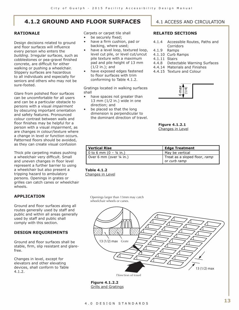
Changes in level, except for elevators and other elevating devices, shall conform to Table 4.1.2.
Carpets or carpet tile shall• be securely fixed;• have a firm cushion, pad or
backing, where used;• have a level loop, textured loop,
level cut pile, or level cut/uncut pile texture with a maximum pad and pile height of 13 mm (1/2 in.); and
• have exposed edges fastened to floor surfaces with trim conforming to Table 4.1.2.
Gratings located in walking surfaces shall • have spaces not greater than
13 mm (1/2 in.) wide in one direction; and
• be placed so that the long dimension is perpendicular to the dominant direction of travel.
Vertical Rise Edge Treatment0 to 6 mm (0 – ¼ in.) May be verticalOver 6 mm (over ¼ in.) Treat as a sloped floor, ramp
or curb ramp
Table 4.1.2Changes in Level
6 m
ax
(1/
4)
13 (1/2) max
13 (1/2) max
4.1 ACCESS AND CIRCULATION
RELATED SECTIONS
4.1.4 Accessible Routes, Paths and Corridors
4.1.9 Ramps4.1.10 Curb Ramps4.1.11 Stairs4.4.8 Detectable Warning Surfaces4.4.14 Materials and Finishes4.4.15 Texture and Colour
Figure 4.1.2.1Changes in Level
Figure 4.1.2.2Grills and Gratings

14
C i t y o f G u e l p h - 2 0 1 5 F a c i l i t y A c c e s s i b i l i t y D e s i g n M a n u a l
4 . 0 D E S I G N S T A N D A R D S
RATIONALE
The creation of accessible routes free from protruding objects or freestanding obstacles is important to all facility users. An object protruding from a wall above the detection range of a cane is dangerous for an individual with a visual impairment or a pedestrian distracted by a conversation. The underside of stairways is a common overhead hazard. Temporary construction barriers can also be hazardous if their lower edge is too high to be detected by a person using a long white cane for mobility. Detectable surfaces around freestanding obstacles, such as light standards, are advantageous to anyone using the route.
APPLICATION
Protruding objects from a wall, ceiling or other location shall comply with this section.
DESIGN REQUIREMENTS
Objects protruding from walls with their leading edges between 680 mm (26-1/2 in.) and 2100 mm (82-3/4 in.) from the floor shall protrude not more than 100 mm (4 in.) into pedestrian areas, such as walkways, halls, corridors, passageways or aisles.
Objects attached to a wall with their leading edges at or below 680 mm (26-1/2 in.) from the floor may protrude any amount.
Freestanding objects shall not have any overhang of more than 300 mm (12 in.) between 680 mm (26-1/2 in.) and 2100 mm (82-3/4 in.) from the ground or floor.
The maximum height of the bottom edge of freestanding objects with a space of more than 300 mm (11-3/4 in.) between supports shall be 680 mm (26-1/2 in.) from the ground or floor.
4.1.3 PROTRUDING & OVERHEAD OBJECTS4.1 ACCESS AND CIRCULATION
680 max (26-1/2)
2100
min
(82-
3/4)
AN
Y H
EIG
HT
100 max
Ob
stru
ctio
n
2100
min
(8
2-3/
4)
(4)
(26
1/2)
>100
Ob
stru
ctio
n
CLEAR
CANE HITS OBSTRUCTION
WIDTH (4)
680
max
Protruding objects shall not reduce the clear width required for an accessible route or manoeuvring space.
The minimum clear headroom in pedestrian areas, such as walkways, halls, corridors, passageways, or aisles, shall be 2100 mm (82-3/4 in.).
A detectable guard: a guardrail or other barrier having its leading edge at or below 680 mm (26-1/2 in.) from the floor shall be provided where the headroom of an area adjoining an accessible route is reduced to less than 2100 mm (82-3/4 in.).
RELATED SECTIONS
4.1.4 Accessible Routes, Paths and Corridors
4.4.8 Detectable Warning Surfaces4.4.14 Materials and Finishes4.4.15 Texture and Colour
Figure 4.1.3.1Limits of Protruding Objects
Figure 4.1.3.2Limits of Protruding Objects
Figure 4.1.3.3Overhead Obstructions

C i t y o f G u e l p h - 2 0 1 5 F a c i l i t y A c c e s s i b i l i t y D e s i g n M a n u a l
15 4 . 0 D E S I G N S T A N D A R D S
RATIONALE
Routes of travel through a facility should address the full range of individuals that may use them. They must provide the clear width necessary for persons using wheelchairs or scooters, those pushing strollers or those travelling in pairs. Consideration should be given not just to the width of items, such as wheelchairs and scooters, but also to their manoeuvrability. While a corridor may be wide enough for a person to drive a scooter in a straight line, it may not be possible to make a turn around a corner. The preferred minimum width for accessible routes is 1830 mm (72 in.).
Strong colour contrasts and/or tactile pathways set into floors may be used to assist individuals with a visual impairment to negotiate an environment. Edge protection that guards a change in level is an important safety feature for all users.
APPLICATION
Wherever possible, all routes, paths or corridors shall comply with this section.
At least one accessible route complying with this section shall be provided within the boundary of the site from accessible parking spaces, passenger-loading zones (if provided), and public streets or sidewalks to the accessible facility entrance they serve. The accessible route shall, to the maximum extent feasible, coincide with the route for the general public.
At least one accessible route shall connect accessible buildings, facilities, elements and spaces that are on the same site. It is preferable to have all routes accessible.
If a path or walkway connects two barrier-free storeys in different buildings, the path or walkway that connects the storeys shall be barrier-free.
Except where essential obstructions in a work area would make an accessible route hazardous, an accessible route shall connect accessible entrances with all accessible spaces and elements within the facility. An accessible route complying with this section shall be provided within all normally occupiable floor areas.
Exceptions: The provision of an accessible route does not apply
• to service rooms• to elevator machine rooms• to janitor rooms• to service spaces• to crawl spaces• to attic or roof spaces• to high-hazard industrial
occupancies• within portions of a floor area
with fixed seats in an assembly occupancy where these portions are not part of an accessible route to spaces designated for wheelchair use; or
• within a suite of residential occupancy.
Accessible routes are permitted to include ramps, curb ramps, stairs, elevators or other elevating devices (as permitted in 4.1.15) where there exists a difference in elevation.
4.1.4 ACCESSIBLE ROUTES, PATHS & CORRIDORS 4.1 ACCESS AND CIRCULATION
(43-1/4)
1100 min
1370 min (54)
1830 min (72)
200 (7-7/8)
75 (3) min
Figure 4.1.4.1Edge Protection
Figure 4.1.4.2Access Widths

16
C i t y o f G u e l p h - 2 0 1 5 F a c i l i t y A c c e s s i b i l i t y D e s i g n M a n u a l
4 . 0 D E S I G N S T A N D A R D S
4.1 ACCESS AND CIRCULATION
DESIGN REQUIREMENTS
The minimum clear width of accessible routes shall be 1100 mm (43-1/4 in.) except
• at doors - refer to 4.1.6;• where additional manoeuvring
space is required at doorways (See 4.1.6);
• at U-turns around obstacles less than 1220 mm (48 in.) wide, it shall be 1220 mm (48 in.);
• for exterior routes (not including recreational trails, boardwalks, and beach access routes), it shall be 1500 mm (59 in.) which can be reduced to 1200mm (47 in.) to serve as turning space where path connects to a curb ramp; and
• where space is required for two wheelchairs to pass, it shall be 1830 mm (72 in.).
Accessible routes shall • have a running slope not
steeper than 1:25; and• have a cross slope not steeper
than 1:50.
Curb ramps along an accessible route shall be in compliance with 4.1.10.
Every accessible route less than 1830 mm (72 in.) wide shall be provided with an unobstructed passing space of not less than 1830 mm (72 in.) in width and 1830 mm (72 in.) in length, located not more than 30 meters (98 ft. 5 in.) apart.
Except at stairs and at elevated platforms such as performance areas or loading docks, where the edges of accessible routes, paths or corridors are not level with the adjacent surface, they shall be protected
• by a colour contrasting curb at least 75 mm (3 in.) high where the change in level is 200 mm (7-7/8 in.) to 600 mm (23-5/8 in.) below the route, path or corridor; and
• by a guard which meets the requirements of the Ontario Building Code where the change in level is greater than 600 mm (23-5/8 in.).
Where there is a change in direction along an accessible route and the intended destination of the route is not evident, directional signage shall be provided.
All portions of accessible routes shall be equipped to provide a level of illumination of at least 50 lux (4.6 ft-candles). Exception: Outdoor park settings where routes are not normally illuminated.
Accessible routes, paths or corridors having a slope steeper than 1:25 (4%) shall be designed as ramps, in compliance with 4.1.9.
Where constructing new or redeveloping existing exterior paths of travel that they intend to maintain, obligated organizations, other than small organizations, shall consult on the design and placement of rest areas along the exterior path of travel and shall do so in the following manner:
1) The Government of Ontario, the Legislative Assembly, designated public sector organizations and large organizations must consult with the public and persons with disabilities.2) Municipalities must also consult with their municipal accessibility advisory committees, where one has been established in accordance with subsection 29 (1) or (2) of the Act.
RELATED SECTIONS
4.1.2 Ground and Floor Surfaces4.1.3 Protruding & Overhead
Objects4.1.7 Gates, Turnstiles and
Openings4.1.10 Curb Ramps4.2.3 Elevated Platforms4.4.7 Signage4.4.8 Detectable Warning Surfaces4.4.12 Glare and Light Sources4.4.13 Lighting4.4.14 Materials and Finishes4.4.15 Texture and Colour4.4.17 Pedestrian Signals
4.1.4 ACCESSIBLE ROUTES, PATHS & CORRIDORS
1100 min (43-1/4)
1100 min (43-1/4)
1100
min
(43
-1/4
)
1220 or greater(48 or greater)
1100 min (43-1/4)
1100 min (43-1/4)
1220
min
(4
8)
less than 1220 (48)
Figure 4.1.4.3Turn around an Obstacle
Figure 4.1.4.4Turn around an Obstacle

C i t y o f G u e l p h - 2 0 1 5 F a c i l i t y A c c e s s i b i l i t y D e s i g n M a n u a l
17 4 . 0 D E S I G N S T A N D A R D S
If the only entrance to a facility or tenancy is a service entrance, that entrance shall be accessible.
Entrances which are not accessible shall have directional signage complying with 4.4.7 which indicates the nearest accessible entrance.
Accessible entrances shall be identified with signage complying with applicable provisions of 4.4.7.
RELATED SECTIONS
4.1.1 Space and Reach Requirements
4.1.6 Doors4.1.7 Gates, Turnstiles and
Openings4.1.8 Windows, Glazed Screens
and Sidelights4.4.2 Controls and Operating
Mechanisms4.4.7 Signage4.4.10 Information Systems4.4.11 Card Access, Safety and
Security Systems4.4.13 Lighting
Accessible public entrances must be provided in a number at least equivalent to the number of exits required by the Ontario Building Code. (This paragraph does not require an increase in the total number of public entrances required for a facility.)
An accessible public entrance must be provided to each tenancy in a facility.
In police stations and municipal courts subject to 4.5.8 and 4.5.9, public entrances that are secured shall be accessible, as required in 4.5.8 and 4.5.9.
If direct access is provided for pedestrians from an enclosed parking garage to the facility, at least one direct entrance from the parking garage to the facility must be accessible.
If access is provided for pedestrians from a pedestrian tunnel or elevated walkway, one entrance to the facility from each tunnel or walkway must be accessible.
RATIONALE
Design decisions concerning entrances will have an immediate impact on the independence and dignity of everyone entering a facility. Entrances that address the full range of individuals using the facility promote a spirit of inclusion that separate accessible entrances do not. Features such as canopies can limit the influence of weather conditions on this already busy area and also make an entrance more obvious to someone with a cognitive disability or someone unfamiliar with the facility.
APPLICATION
A minimum of 50% of entrances used by staff or the public shall be accessible and comply with this section.
Primary entrances used by staff and the public shall be accessible.
Accessible entrances shall lead from the outdoors at sidewalk level, or a ramp that leads from a sidewalk.
4.1.5 ENTRANCES 4.1 ACCESS AND CIRCULATION

18
C i t y o f G u e l p h - 2 0 1 5 F a c i l i t y A c c e s s i b i l i t y D e s i g n M a n u a l
4 . 0 D E S I G N S T A N D A R D S
4.1.6 DOORS
RATIONALE
Sufficiently wide doorways will be advantageous to individuals using wheelchairs, pushing strollers, or making a delivery. However, a raised threshold at the base of the door could impede any one of these same individuals. This same group, with the addition of children, seniors or even someone carrying packages, would have difficulty opening a heavy door and would benefit from some form of automatic door opener. Entrances without doors are preferred.
Independent use of doors is desirable. Reliance on assistance from others to open doors is not an accessible or dignified solution.
Careful thought to the direction of the door swing can enhance the usability and limit the hazard to other pedestrians. Sliding doors can be easier for some individuals to operate, and can also require less wheelchair manoeuvring space. Doors that require two hands to operate are not considered to be accessible. Revolving doors are not accessible for persons using wheelchairs and strollers. Also, the coordination required to use such doors may be difficult for children or someone with a cognitive disability.
Glazed doors can present a hazard to all individuals and especially those with a visual impairment. The inclusion of colour-contrast strips across the glass, mounted at eye level, as well as colour-contrasting door frames and door hardware, will increase the safety and visibility of a glazed door for a person with a visual impairment.
APPLICATION
All exterior and interior doors used by staff or the public shall comply with this section. In a retrofit situation where it is technically infeasible to make all doors accessible, at least one door at each accessible space shall comply with this section.
Exception: Doors not requiring full user passage, such as shallow closets, may have the clear opening reduced to 510 mm (20 in.) minimum.
Each door that is an element of an accessible route shall comply with this section.
Each door required by 4.4.1 (Emergency Exits, Fire Evacuation and Areas of Refuge) shall comply with this section.
Where a door system incorporates multiple door leafs at a single location, at least one of the door leafs shall comply with this section.
Power operators shall be provided at the following door locations:
• entrances required by 4.1.5, including both inner and outer vestibule doors (where provided);
• washrooms that include an accessible toilet stall, where there is no universal washroom on the same floor within 45 m (147 ft 6 in.). Exception: Where there is at least one other male and female washroom with accessible toilet stalls on the same floor within 45m (147 ft. 6 in.), that are equipped with a power door operator;
• universal washrooms;• accessible change rooms;• intermediate doorways across
primary circulation routes within a facility. Exception: Doors that are held-open using electromagnetic hold-open devices; and
• entrances into primary functional areas within a facility, as designated by the member organization of the City of Guelph. Exception: Doors that are held-open using electromagnetic hold-open devices.
Mats and mat sinkages at doors shall comply with this section.
Floor Space Required (in mm)ContextDepth Width Space beside
latchSide-hinged door - Front approach (Figure 4.1.6.3)
Pull side 1525 (60 in.) 1600 (63 in.)(*1525 (60 in.))
600 (23-5/8 in.)
Push side 1370 (54 in.) 1250 (49-1/4 in.)(*1220 (48 in.))
300 (11-3/4 in.)
Side-hinged door - Latch-side approach (Figure 4.1.6.2)
Pull side 1370 (54 in.)(*1220 (48 in.))
1600 (63 in.)(*1525 (60 in.))
600 (23-5/8 in.)
Push side 1370 (54 in.) 1525 (60 in.) 600 (23-5/8 in.)
Side-hinged door - Hinge-side approach (Figure 4.1.6.1)
Pull side 2440 (96 in.)(*1525 (60 in.))
2440 (96 in.)(*1525 (60 in.))
600 (23-5/8 in.)
Push side 1370 (54 in.) 1830 (72 in.) 450 (17-3/4 in.)
Sliding door (Figure 4.1.6.4)
Front approach 1370 (54 in.) 1500 (61 in.) 300 (11-3/4 in.)
Side approach 1370 (54 in.) 2150 (84-5/8 in.) 600 (23-5/8 in.)
(*1100 (43-1/4 in.))
(*1100 (43-1/4 in.))
(*1100 (43-1/4 in.))
Table 4.1.6 Manoeuvring Space at Doors In retrofit situations where it is technically infeasible to provide the required clearances at doors, the clearances may be reduced as shown by the asterix (*).
4.1 ACCESS AND CIRCULATION

C i t y o f G u e l p h - 2 0 1 5 F a c i l i t y A c c e s s i b i l i t y D e s i g n M a n u a l
19 4 . 0 D E S I G N S T A N D A R D S
Revolving doors or turnstiles shall not be the only means of passage at an accessible entrance or along an accessible route. An accessible gate or door shall be provided adjacent to the turnstile or revolving door and shall be designated to facilitate the same use pattern.
Frameless glass doors shall not be used.
Door hardware on all doors throughout a facility (not only those deemed accessible), shall comply with the door hardware requirements of this section.
4.1.6 DOORS 4.1 ACCESS AND CIRCULATION
1600 min (63)
600 min(23-5/8)
(49)
1525
min
(60)
300 min(11-3/4)
1370
min
(54)
Pull Side
Push Side
1250 min
1550 min (61)
600 min (23-5/8)
2150 min (84-5/8)
1370
min
(54)
1370
min
(54)
300 min (11-3/4)
300 min (11-3/4)
600 min (23-5/8)
1600 min (63)
600 min (23-5/8)
1525 min (60)
1370
min
(54)
1370
min
(54)
Pull Side
Push Side
2440 min (96)
2440
min
(96)
450 min (17-3/4)
600 min (23-5/8)
1830 min (72)
1370
min
(54)
Pull Side
Push Side
Figure 4.1.6.1 Hinge Side Approach at Hinged Doors
Figure 4.1.6.3 Front Approach at Hinged Doors
Figure 4.1.6.2 Latch Side Approach at Hinged Doors
Figure 4.1.6.4Front and Side Approach at Sliding Doors
DESIGN REQUIREMENTS
Accessible doors shall be on an accessible route that complies with 4.1.4.
The minimum width of a door leaf in accessible door systems shall be 965 mm (38 in.). In retrofit situations where it is technically infeasible to provide this size of door leaf, a 920 mm (36") door leaf may be used.
Unless equipped with a power door operator, doors shall have level wheelchair-manoeuvring space on both sides of the door, and clear space beside the latch, as described in Table 4.1.6. Exception: The clear space is not required on the inactive side of a door, where access is provided from one side only - such as to a closet.

20
C i t y o f G u e l p h - 2 0 1 5 F a c i l i t y A c c e s s i b i l i t y D e s i g n M a n u a l
4 . 0 D E S I G N S T A N D A R D S
4.1.6 DOORS4.1 ACCESS AND CIRCULATION
DESIGN REQUIREMENTS (Continued)
The required clear space beside the latch is to be unobstructed for the full height of the door.
The minimum space between two hinged or pivoted doors in series shall be 1500 mm (59 in.), plus the width of any door swinging into the space. Where doors in a series are not aligned, a turning diameter of 1500 mm (59 in.) shall be provided within the vestibule area, clear of any door swing.
Thresholds shall be not more than 6 mm (1/4 in.) high.
Door hardware (operating devices such as handles, pulls, latches, and locks) shall• be operable by one hand;• not require fine finger control,
tight grasping, pinching, or twisting of the wrist to operate (designed to be operable using a closed fist); and
• be mounted between 900 mm (35 in.) and 1100 mm
(43-1/4 in.) from the floor.
Operating hardware on sliding doors shall be exposed and usable from both sides when sliding doors are fully open.
The maximum door opening force for pushing or pulling open a door shall be • 38 N (8.5 lb.) for exterior
hinged doors;• 22 N (4.6 lb.) for interior hinged
doors; and• 22 N (4.6 lb.) for sliding or
folding doors.
1525
min
(60)
600 min(23-5/8)
300min (11-3/4)
30
0 m
in
1370 min (54)
(11-
3/4)13
70 m
in
(5
4)
1250
min
(49)
1600 min (63)
1500 (59)turn space
1600 min (63)
600 min (23-5/8)
1250 min (49)
1500
min
(59)
1525
min
(60)
300 min (11-3/4)
1370
min
(54)
Do
or
Wid
th 600 min (23-5/8)
Figure 4.1.6.6 Manoeuvring Space at Doors in Series
Figure 4.1.6.5 Manoeuvring Space at Doors in Series
Door closers shall be adjusted to the least pressure possible, but never more than the opening forces noted above.
The sweep period of door closers shall be adjusted so that, from an open position of 90 degrees, the door will take not less than 3 seconds to move to a semi-closed position of approximately 12 degrees.
Power-assisted swinging doors shall• take not less than 3 seconds
to move from the closed to the fully open position; and
• require a force of not more than 66 N (13.8 lb.) to stop door movement.
Permanent mats and metal gratings at entrances and in vestibules shall be sunk level with the floor, so as not to create a tripping hazard.

C i t y o f G u e l p h - 2 0 1 5 F a c i l i t y A c c e s s i b i l i t y D e s i g n M a n u a l
21 4 . 0 D E S I G N S T A N D A R D S
680 max (26 1/2)
300 min (12)
Figure 4.1.6.8 Detectable Safety Guards
Figure 4.1.6.7 Examples ofAccessible Hardware
4.1.6 DOORS 4.1 ACCESS AND CIRCULATION
Occasional mats (e.g. runners used in bad weather) should be level with the floor surface and/or have a gently bevelled edge, so as not to create a tripping hazard.
Where power door operators are provided they shall
• be located to allow a person using a wheelchair or scooter to stop immediately adjacent to the control (refer to 4.1.1);
• be located at least 600 mm (23-5/8 in.) from any inside corner;
• be located on the latch side of door it controls so as to allow persons to activate the opening of the door from either side
• be located not less than 600 mm (23-5/8 in.) and not
more than 1500 mm (59 in.) beyond the door swing, where the door opens towards the control;
• incorporate controls that are clearly visible which are at least 150 mm (5-7/8 in.) in diameter, or at least 150 mm (5-1/8 in.) by 914 mm (36 in.) touch panel;
• have its centre located 1000 - 1100 mm (39-3/8 - 43-1/4 in.) from the finished floor, or extending not more than 200 mm (7-7/8 in.) to not less than 900 mm (35-1/2 in.) above the finished floor or ground;
• incorporate the International Symbol of Access for Persons with Disabilities;
• where pressure-sensitive mats, overhead beams or proximity scanners are used to detect traffic, incorporate systems that will detect individuals using wheelchairs; and
• where exterior doors swing open into a pedestrian area, incorporate safety guards that comply with 4.1.3, projecting a minimum of 300 mm (11-3/4 in.) beyond both sides of the open door. (See Figure 4.1.6.8)
Where doors are not equipped with a closing device, the edge of door shall be colour contrasted to the face of the door. (See Figure 4.1.6.9)
Doors and/or door frames shall incorporate pronounced colour contrast, to differentiate them from the surrounding environment. Door handles and other operating mechanisms shall incorporate pronounced colour contrast, to differentiate them from the door itself.
Where a door incorporates glazing or is fully glazed, it shall comply with Section 4.1.8 (Windows, Glazed Screens and Sidelights).
RELATED SECTIONS
4.1.1 Space and Reach Requirements
4.1.7 Gates, Turnstiles and Openings
4.1.8 Windows, Glazed Screens and Sidelights
4.4.2 Controls and Operating Mechanisms
4.4.7 Signage4.4.10 Information Systems4.4.11 Card Access, Safety and
Security Systems
Colour contrast door edgewhere door not equipped with closer
Colour contrast door frame
Colour contrast door
Colour contrast hardware
Example 1 Example 2
Figure 4.1.6.9 Colour Contrast at Doors

22
C i t y o f G u e l p h - 2 0 1 5 F a c i l i t y A c c e s s i b i l i t y D e s i g n M a n u a l
4 . 0 D E S I G N S T A N D A R D S
4.1.7 GATES, TURNSTILES AND OPENINGS
RATIONALE
Gates and turnstiles should address the full range of users that may pass through them. Single-bar gates designed to be at a convenient waist height for ambulatory persons are at neck and face height for children and persons who use wheelchairs or scooters.
Revolving turnstiles are a physical impossibility for a person in a wheelchair to negotiate. They are also difficult for persons using canes or crutches, or persons with poor balance. An adjacent opening of an appropriate width is essential for wheelchair access, as well as access for those using other mobility devices, strollers, walkers or delivery carts.
APPLICATION
Gates, turnstiles and openings shall comply with this section.
DESIGN REQUIREMENTS
Where gates or openings are provided through fences or screens to public use areas, such openings shall be accessible (i.e., a minimum of 950 mm (37-1/2 in.) wide, to allow free passage of a person in a wheelchair. Hardware should be suitable for autonomous use, and any closing device should not be spring-loaded).
Where turnstiles or other ticketing control devices which are not wheelchair accessible are utilized, then a gate or opening which is accessible shall also be provided in the same location.
Turnstiles shall incorporate a pronounced colour contrast, to differentiate them from the surrounding environment.
Where gates are incorporated into a chain-link fencing system, the poles at either side of the gate shall incorporate a pronounced colour contrast from the fence and the surrounding environment.
RELATED SECTIONS
4.1.1 Space and Reach Requirements
4.1.6 Doors4.1.8 Windows, Glazed Screens
and Sidelights4.4.2 Controls and Operating
Mechanisms4.4.7 Signage4.4.10 Information Systems4.4.11 Card Access, Safety and
Security Systems
950 min
InaccessiblePosts
InaccessibleTurnstile
(37 1/2)
4.1 ACCESS AND CIRCULATION
Figure 4.1.7.1 Access at Turnstile
680
max
(26-
1/2)
Figure 4.1.7.2 Access at Turnstile

C i t y o f G u e l p h - 2 0 1 5 F a c i l i t y A c c e s s i b i l i t y D e s i g n M a n u a l
23 4 . 0 D E S I G N S T A N D A R D S
760
max
(30)
4.1.8 WINDOWS, GLAZED SCREENS & SIDELIGHTS
RATIONALE
Broad expanses of glazing in screens, sidelights and doors can be difficult to detect. While this may be a particular concern to persons with visual impairments, it is possible for anyone to walk into a clear sheet of glazing, especially if they are distracted or in a hurry.
Persons who use wheelchairs or scooters experience the facility from a seated position thereby lowering their eye level and reach range. This necessitates the need for lower sill heights and easily reached operating mechanisms. Window controls and operating devices should also respect the limitations of hand strength or dexterity encountered with different types of disabilities, including arthritis.
APPLICATION
Windows, glazed screens, fully- glazed sidelights, fully-glazed doors and vision panels in doors shall comply with this section.
Frameless glass doors shall not be used.
DESIGN REQUIREMENTS
Fully-glazed sidelights at exterior entrances or vestibules, as well as fully-glazed screens, shall be clearly identified with a horizontal row of decals, or a continuous stripe, minimum 50 mm (2 in.) wide and of highly contrasting colour, mounted with its centre line between 1475 mm (58 in.) and 1525 mm (60 in.) from the floor or ground. Additionally, a second row of decals, or a continuous stripe, a minimum 50 mm (2 in.) wide and of highly contrasting colour shall be provided, mounted with its centreline between 1170 mm (46 in.) and 1220 mm (48 in.) above the floor or ground.
Where decals are used, they shall be located at a maximum of 150 mm (5-7/8 in.) from centre to centre. The decals can either be 50 mm (2 in.) square or round, and/or of a special design (e.g., a logo) provided the solid portion of the decals provides high colour contrast and is easy to identify by persons who are visually impaired.
Where etched or patterned glass is used, decals or a stripe of highly contrasting colour shall still be provided.
Where frameless glass panels are used, exposed edges shall be identified with a vertical safety stripe, applied to cap the end glass panel.
Where viewing windows or vision panels are provided,
• the sill height shall be no more than 760 mm (30 in.) from the floor; and
• where horizontal transoms are incorporated in windows, the transoms shall not be located between 1060 mm (42 in.) and 1220 (48 in.) from the floor.
Where peepholes are used, they shall be of the wide angle variety that allows the viewer to be at a range of heights or angles
In facilities with operable windows, window opening hardware shall
• be mounted between 400 mm (15-3/4 in.) and 1200 mm (47 in.) from the floor;
• be operable using one hand; and
• not require fine finger control, tight grasping, pinching, or twisting of the wrist to operate.
RELATED SECTIONS
4.1.1 Space and Reach Requirements4.4.2 Controls and Operating Mechanisms
Figure 4.1.8.1 Window Sill Height
4.1 ACCESS AND CIRCULATION

24
C i t y o f G u e l p h - 2 0 1 5 F a c i l i t y A c c e s s i b i l i t y D e s i g n M a n u a l
4 . 0 D E S I G N S T A N D A R D S
2440 min
(96)
2440 min
(96)2440 m
in
(96)
2440 min
(96)
2440 min
(96)
2440 min
(96)
2440 min
(96)
2440 min
(96)
2440 min (96)
2440min (96)
1670 min (65-3/4)
9000 max (29'-6")
9000 max (29'-6")
2440min (96)
9000 max (29'-6")
9000 max (29'-6")
1 in 20 max slope *
1 in 20 max slope *
1 in 20 max slope *
1 in 20 max slope *
* In a retrofit situation where it is technically infeasible to provid etherequired maximum slope, the maximumslope may be increased up to 1:15
1670 min (65-3/4)
1670 min (65-3/4)
1670 min (65-3/4)
4.1.9 RAMPS
RATIONALE
Traditionally, ramps have been synonymous with wheelchair accessibility. However, ramps can be problematic in providing accessibility. Ramps can be difficult and dangerous to negotiate. Also, the physical space required for ramps makes them cumbersome to integrate into a facility. However, where a change in level already exists or cannot be avoided, a properly designed ramp can provide access for those using wheelchairs, pushing strollers or moving packages on a trolley.
The design of the ramp is critical to its usefulness and safety. A steeply inclined ramp is difficult to ascend when using a wheelchair, and can increase the risk of the wheelchair tipping backwards. Descending a steep ramp can also be hazardous. Any cross slope will further increase the effort required to negotiate the ramp. Manoeuvring space at the top and bottom are other important factors in a ramps usability. Level areas at points along a long ramp enable an individual to rest.
Textured surfaces, edge protection and handrails all provide important safety functions. Heated surfaces are recommended to address the safety concerns associated with snow and ice.
APPLICATION
Any part of an accessible route with a slope steeper than 1:25 shall be considered a ramp and shall comply with this section.
DESIGN REQUIREMENTS
Accessible ramps shall be on an accessible route complying with 4.1.4.
The running slope shall be between 1:20 and 1:25. In a retrofit situation where it is technically infeasible to provide a ramp with a running slope between 1:20 and 1:25, a running slope not steeper than 1:15 may be used. Shallower slopes are preferred.
The maximum cross slope of ramp surfaces shall be 1:50.
Ramps shall have level landings at the top and bottom of each run and also where the ramp changes direction.
The maximum horizontal length between landings shall not exceed 9 m (29’-6”).
Landings shall
• be at least as wide as the widest ramp run leading to it;
• provide a minimum clear turning space not less than 2440 x 2440 mm (96 x 96 in.) if located at the top or bottom of a ramp or if served by a doorway. (In a retrofit situation where creating a suitably sized landing is technically infeasible,
Figure 4.1.9.1 Minimum Ramp Landing Dimensions
4.1 ACCESS AND CIRCULATION

C i t y o f G u e l p h - 2 0 1 5 F a c i l i t y A c c e s s i b i l i t y D e s i g n M a n u a l
25 4 . 0 D E S I G N S T A N D A R D S
the required landing size may be reduced to 1670 x 1670 mm. (65-3/4 x 65-3/4 in.));
• where an intermediate landing at the switchback of a U-shaped ramp (Refer to Figure 4.1.9.1), have a length not less than 1670 mm (65-3/4 in.) and a width not less than 2440 mm (96 in.). In a retrofit situation where creating a suitably sized landing is technically infeasible, the required landing width may be reduced to 2120 mm (84in));
• where an intermediate landing at a change of 90 degrees or more in the direction of the ramp (Refer to Figure 4.1.9.1), have a length and width not less than 1670 mm (65-3/4 in.); and
• where an intermediate landing at a straight ramp (Refer to Figure 4.1.9.1), have a length not less than 1670 mm (65-3/4 in.).
Ramp and landing surfaces shall be firm, stable, and slip-resistant, complying with section 4.1.2.
Outdoor ramps and their approaches shall be designed so that water will not accumulate on walking surfaces.
Surface cross slope shall not be greater than 1:50
Edges of ramps and landings shall be protected with a wall or guard on all sides.
Where a guard is provided, it shall
• comply with the requirements of the Ontario Building Code;
• be provided with a curb at least 50 mm
(2 in.) high on any side of the ramp where no solid enclosure or solid guard is provided; and
with railings or other barriers that extend to within 50 mm (2 in.) of the finished ramp, or have a curb not less than 50 mm (2 in.) high.
4.1.9 RAMPS
2440 min (96)
2440 min (96)
950-1100mm(37 1/2 - 43 1/4in.)between handrails
Slope no steeperthan 1:20
2440 min
(96)
Figure 4.1.9.2 Ramp Criteria
4.1 ACCESS AND CIRCULATION

26
C i t y o f G u e l p h - 2 0 1 5 F a c i l i t y A c c e s s i b i l i t y D e s i g n M a n u a l
4 . 0 D E S I G N S T A N D A R D S
4.1.9 RAMPS
50 max (2)
50 min (2)
50 max (2)
300 min(11-3/4)
Handrail returnsto post
Handrail returnsto floor
Handrail returnsto wall
300 min(11-3/4)
300 min(11-3/4)
Figure 4.1.9.3Horizontal Handrail Extensions
Figure 4.1.9.4Edge Protection at Ramps
4.1 ACCESS AND CIRCULATION
DESIGN REQUIREMENTS(Continued)
A ramp run with a rise greater than 150 mm (6 in.) shall have handrails which
• are on both sides;• comply with 4.1.12;• are continuous on the inside
of switchback (U-shaped) or L-shaped ramps;
• when not continuous, extend horizontally at least 300 mm (12 in.) beyond the top and bottom of the ramp and return to the wall, floor, or post;
• be terminated in a manner that will not obstruct pedestrian travel or create a hazard;
• measure between 865 mm (34 in.) and 920 mm (36 in.) from the ramp surface to the top of the handrail; and
• have a width between at least one set of handrails of 950 - 1100 mm (37-1/2 - 43-1/4 in.).
Where a ramp is greater than 2200 mm (86-1/2 in.) in width, one or more intermediate handrails which are continuous between landings and comply with 4.1.12 must be provided and located so that there is a MAX 1650 mm (65 in.) between handrails.
EXCEPTION: Where a ramp serves as an aisleway for fixed seating, the requirements for ramp handrails do not apply.
RELATED SECTIONS
4.1.1 Space and Reach Requirements
4.1.2 Ground and Floor Surfaces4.1.6 Doors4.1.10 Curb Ramps4.1.12 Handrails4.4.7 Signage4.4.8 Detectable Warning Surfaces4.4.12 Glare and Light Sources4.4.13 Lighting4.4.14 Materials and Finishes4.4.15 Texture and Colour

C i t y o f G u e l p h - 2 0 1 5 F a c i l i t y A c c e s s i b i l i t y D e s i g n M a n u a l
27 4 . 0 D E S I G N S T A N D A R D S
Safe
pedestr ia n
cr ossing
route
150-200 gap
1220 min
Detectable warning surface
Slope on flaredsides 1:10 max
(48)
0 min
0 5 1 (5
9) 0 0 7
0 0 7 (27-1/2)
(27-1/2)
610 (24)
min
min
Figure 4.1.10.2Depressed Curb where Sidewalks are adjacent to Curb
Figure 4.1.10.1Curb Ramp with Flared Sides
RATIONALE
In the interest of moving people safely and efficiently off a roadway, the design of curb ramps is very important. The same issues related to the slopes of ramps apply equally to slopes of curb ramps. A well-designed curb ramp can be spoiled by an uneven or gapped transition between the road surface and curb ramp. Flared sides on the curb ramp eliminate the hazard of pedestrians stepping off of an edge. While a smooth transition and minimal slope are ideal for someone in a wheel-chair, they are a potential hazard to an individual with a visual impair-ment who may not notice the tran-sition from sidewalk to street. Tex-tured surfaces become an important safety feature in this scenario.
APPLICATION
Curb ramps complying with this section shall be provided wherever any path of travel crosses a curb.
DESIGN REQUIREMENTS
Accessible curb ramps shall be on an accessible route complying with 4.1.4.
The running slope shall be between 1:50 and 1:20 (2%-5%). In a retrofit situation where it is impractical to achieve these slopes, a running slope no steeper than 1:12 (8.3%)may be used.
The minimum width of curb ramps, exclusive of flared sides, shall be 1500 mm (59 in.).
The maximum allowable cross slope shall be no more than 1:50.
The maximum slope on flared sides shall be no more than 1:10
Curb ramp configuration shall be as illustrated in Figures 4.1.10.1 to 4.1.10.5.
The maximum counter slope of gutters and road surfaces immediately adjacent to curb ramps shall be 1:20.
4.1.10 CURB RAMPS 4.1 ACCESS AND CIRCULATION
0 07
Sidewalk
(27-1/2)
(118)
3000 min
Depressed Curb
Full widthsidewalk
Full width
sidewalk
1220
150-200 gap
Detectable warning surface
610
(24)
min
1220 min (48)clear distance
(48)
(5-7/8 - 7-7/8)
S a f e pedestrian
crossing route
S a f e pedestrian
crossing route
007
007
0 min051
(59)
L=1000 min
150-200 gap
610
(39-3/8)
Sidewalk
(27-1/2)
(27-1/2)
Safepedestrian
crossingroute Detectable
warning surfaceNote: If L<1000 use depressed curb
min
min
Curb Ramp
Sidewalk
(5-7/8 - 7-7/8)
(24)
S af e
pedestrian
c rossing
r oute
Figure 4.1.10.3Curb Ramp at Sidewalks with Wide Boulevards

28
C i t y o f G u e l p h - 2 0 1 5 F a c i l i t y A c c e s s i b i l i t y D e s i g n M a n u a l
4 . 0 D E S I G N S T A N D A R D S
min 370
1 (54)
0 min
051 (59)
007
007 (27-1/2)
(27-1/2)
Safe
pedestr ian
crossing
route
Level RestArea
MedianBoulevard
min
min
Curb Ramp
150-200 gap 610(24)
Detectable warning surface
(5-7/8 - 7-7/8)
4.1.10 CURB RAMPS4.1 ACCESS AND CIRCULATION
DESIGN REQUIREMENTS(Continued)
Surfaces of curb ramps shall
• be slip-resistant;• have a smooth transition from
the curb ramp to adjacent surfaces; and
• incorporate a truncated cone/dome detectable warning surface;• in compliance with 4.4.8;• located at the bottom of the
curb ramp;• having high tonal contrast
with adjacent surfaces;• a minimum 610 mm (23-
5/8 in.) deep, commencing 150 - 200 mm (5-7/8 - 7-7/8 in.) from the back of the curb edge; and
• extending the full width of the curb ramp.
Curb ramps at pedestrian crosswalks shall be wholly contained within the area designated for pedestrian use.
Raised islands in crossings shall
• be cut through level with the street; or
• have curb ramps at both sides and a level area not less than 1370 long (54 in.) in the middle.
Islands level with the street shall have within the area designated for pedestrian use detectable warning surfaces in compliance with section 4.4.8.
Figure 4.1.10.4Curb Ramp at Wide Median Sidewalk Crossing
Depressed Curbs:
Where a depressed curb is provided on an exterior path of travel, the depressed curb must:• have a maximum running slope
of 1:20 (5%)• be aligned with the direction of
travel.• where provided at a pedestrian
crossing, it must have tactile walking surface indicators that,• comply with section 4.4.8;• have high tonal contrast
with the adjacent surface;• are located at the bottom
portion of the depressed curb that is flush with the roadway;
• are set back 150 - 200 mm (5-7/8 - 7-7/8 in.) from the curb edge; and
• are a minimum of 610 mm (24 in.) in depth.
RELATED SECTIONS
4.1.1 Space and Reach Requirements
4.1.2 Ground and Floor Surfaces4.4.8 Detectable Warning Surfaces4.4.12 Glare and Light Sources4.4.14 Materials and Finishes4.4.15 Texture and Colour
0 min051 (5
9)
Safe
pedestrian
cr ossing
route
610 (24)
gap
Detectable warning surfaces
150-200Figure 4.1.10.5Curb Ramp at Narrow Median Sidewalk Crossing

C i t y o f G u e l p h - 2 0 1 5 F a c i l i t y A c c e s s i b i l i t y D e s i g n M a n u a l
29 4 . 0 D E S I G N S T A N D A R D S
4.1.11 STAIRS
RATIONALE
Stairs that are comfortable for many adults may be challenging for children, seniors or persons of short stature. Poorly designed nosings can present tripping hazards, particularly to persons with prosthetic devices or those using canes. Cues to warn a person with a visual impairment of an upcoming set of stairs are vitally important. These persons will also benefit from stairs designed with contrasting edges on treads. The appropriate application of handrails will aid all users and especially those that have difficulty ascending stairs.
APPLICATION
Interior and exterior stairs shall comply with this section.
In a retrofit situation, stairs need not comply if they connect levels that are accessible by an elevator, ramp or other accessible means of vertical access.
In a retrofit situation, dimensional changes to steps and landings are not required. All other design requirements must be met.
DESIGN REQUIREMENTS
A flight of stairs shall have
• uniform riser heights and tread depths;
• risers not more than 180 mm (7 in.) and not less than 125 mm (4-7/8 in.) high;
• run not less than 280 mm (11 in.) and not more than 355 mm (14 in.) deep, measured from riser to riser;
• slip resistant tread surface; and;• no open risers.
Nosings shall
• project not more than 25 mm (1 in.);
• have no abrupt undersides; • have a curved or bevelled leading
edge of the tread between 6 mm (1/4 in.) and 10 mm (3/8 in.);
• where projecting, be sloped to the riser at an angle not less than 60 degrees to the horizontal;
• be illuminated to a level of at least 100 lux (9.2 ft-candles);
• be slip-resistant; and• have high tonal contrast
markings that extend the full width of leading edge of step.
Stairs shall incorporate detectable warning surfaces that comply with 4.4.8, at the top of all flights of stairs, and at all landings.
Handrails for stairs shall
• comply with 4.1.12;• be installed on both sides;• be of uniform height, ranging
between 865 mm (34 in.) and 920 mm (36 in.) from the stair nosing;
• have a continuous inside handrail on switchback stairs; and
• where not continuous• extend at the bottom of the
stairs for a distance of one tread depth beyong the first riser, then horizontally not less than 300 mm (11-3/4 in.), at a height ranging between 865 mm (34 in.) and 920 mm (36 in.) above the floor
• extend horizontally at the top of the stairs not less than 300 mm (11-3/4 in.), at a height ranging between 865 mm (34 in.) and 920 mm (36 in.) above the floor; and
• be terminated in a manner that will not obstruct pedestrian travel or create a hazard.
Where stairs are greater than 2200 mm (86-1/2 in.) in width, one or more intermediate handrails which are continuous between landings and comply with 4.1.12 must be provided and located so that there is MAX 1650 mm (65 in.) between handrails.
RELATED SECTIONS
4.1.1 Space and Reach Requirements4.1.2 Ground and Floor Surfaces4.1.6 Doors4.1.12 Handrails4.4.7 Signage4.4.8 Detectable Warning Surfaces4.4.12 Glare and Light Sources4.4.13 Lighting4.4.14 Materials and Finishes4.4.15 Texture and Colour
4.1 ACCESS AND CIRCULATION
Depth of onestair tread
Depth of onestair tread
300 min
300 min (11-3/4)
300 min (11-3/4)
865-
920
Continuoushandrail Detectable
Warning Surface
(34-
36)
(11-3/4)
Figure 4.1.11.1Stair Design Criteria
Radius 6 -10 (1/4 - 3/8 in.)
Not lessthan 60
25 max
125-180(4-7/8 to 7)
280-355
Visual contrast 40-50 deep onhorizontal and vertical surface of nosing
(11-14)
(1)
Figure 4.1.11.2Stair Tread Criteria
Figure 4.1.11.3Raked Riser

30
C i t y o f G u e l p h - 2 0 1 5 F a c i l i t y A c c e s s i b i l i t y D e s i g n M a n u a l
4 . 0 D E S I G N S T A N D A R D S
4.1 ACCESS AND CIRCULATION 4.1.12 HANDRAILS
RATIONALE
In the design of handrails, consideration must be given to the range of hands that will grasp them. A handrail profile should be graspable for an adult hand as well as a child or a person with arthritis. The same is true for the heights of handrails.
Extensions of the handrails at the top and bottom of stairs, along with the use of a contrasting colour, provide important cues for a visually impaired individual, and provide a support to ensure a safe and stable gait before ascending or descending the stairs. A continuous handrail with no interruptions ensures that a handhold will not be broken.
The clear space between the wall and handrail is also essential, as it must provide a clear area for the hand and knuckles but must not offer space into which the arm may slip during a fall or stumble on the stairs.
APPLICATION
Handrails shall comply with this section.
DESIGN REQUIREMENTS
Handrails shall
• have a circular section 30-40 mm (1-3/16 in. – 1-9/16 in.) in diameter or any non-circular shape, with a graspable portion that has a perimeter not less than 100 mm (4 in.) and not more than 155 mm (6 in.) whose largest cross-sectional dimension is not more than 57 mm (2 in.);
• be free of any sharp or abrasive elements;
• have continuous gripping surfaces, without interruption by newel posts, other construction elements, or obstructions that can break a handhold; and
• have a clear space between the handrail and the wall or guard of at least 50 mm (2 in.); or at least 60 mm (2-3/8 in.)
where the wall has a rough surface.
• be terminated in a manner that will not obstruct pedestrian travel or create a hazard.
A recess containing a handrail shall extend at least 450 mm (17-3/4 in.) above the top of the rail.
Handrails and their supports shall be designed and constructed to withstand the loading values obtained from the nonconcurrent application of
• a concentrated load of not less than 0.9 kN (200 lb.) applied at any point and in any direction; and
• a uniform load of not less than 0.7 kN/m (47 lb./ft.) applied in any direction to the handrail.
Handrails shall incorporate a pronounced colour contrast, to differentiate them from the surrounding environment.
RELATED SECTIONS
4.1.1 Space and Reach Requirements
4.1.9 Ramps4.1.11 Stairs4.4.15 Texture and Colour
(1-3/16 to 1-9/16)
Smooth wall finish
30-40 50 min(2)
(1-3/16 to1-9/16) (2-3/8)
Rough wall finish
60 min 30-40
50 (2) min for smoothwall surfaces
60 min(2-3/8)for roughwall surfaces
450
min
(17
3/4)
30-40(1-3/16 to 1-9/16)
Figure 4.1.12.1Handrail
Figure 4.1.12.2Handrail at Rough Wall
Figure 4.1.12.3Handrail in Recess

C i t y o f G u e l p h - 2 0 1 5 F a c i l i t y A c c e s s i b i l i t y D e s i g n M a n u a l
31 4 . 0 D E S I G N S T A N D A R D S
4.1.13 ESCALATORS
RATIONALE
Boarding and stepping off of an escalator can be challenging for many persons who could have difficulty with the timing or agility. In addition, any lack of contrast on the edge of steps makes it difficult to determine the position of the steps or judge their speed. Detectable warning surfaces extending in front of the escalator provide warning to any pedestrian, especially someone with a visual impairment. Contrasting colour strips on stair edges are also necessary.
APPLICATION
Escalators shall comply with this section.
In a building in which an escalator or inclined moving walk provides access to any floor level above or below the entrance floor level, an interior barrier-free path of travel shall be provided to that floor level.
The route from the escalator or inclined moving walk to the required barrier-free path of travel shall be clearly indicated by appropriate signage.
In a building in which a moving walk provides access between areas on the same floor level, a barrier-free path of travel shall be provided between the areas served by the moving walk.
DESIGN REQUIREMENTS
Escalator installations shall include high definition (colour contrast) of tread edges and nosing.
Detectable warning surfaces that comply with 4.4.8 shall be provided at the head and foot of the escalator.
The surface of escalator treads shall be in a matte finish, to minimize reflected glare.
Lighting over escalators shall be a minimum of 200 lux (18.4 ft-candles), evenly distributed, froma low-glare light source.
RELATED SECTIONS
4.1.1 Space and Reach Requirements
4.1.2 Ground and Floor Surfaces4.4.7 Signage4.4.8 Detectable Warning Surfaces4.4.12 Glare and Light Sources4.4.13 Lighting4.4.14 Materials and Finishes4.4.15 Texture and Colour
4.1 ACCESS AND CIRCULATION

32
C i t y o f G u e l p h - 2 0 1 5 F a c i l i t y A c c e s s i b i l i t y D e s i g n M a n u a l
4 . 0 D E S I G N S T A N D A R D S
4.1.14 ELEVATORS
RATIONALE
The buttons used on elevators need to address a range of functional issues, including reach, dexterity and visual impairments, as discussed in 4.4.2 and 4.4.15. More specific to elevators is the need to provide audible cues for individuals with a visual impairment to identify different floor levels, as well as the direction of travel. These are, in fact, of benefit to anyone who uses the elevator. Adequate door-closing delays provide individuals using mobility devices additional time to reach, enter or exit the elevator car. The installation of a mirror can assist individuals using mobility devices to back out of an elevator where there is not space to turn around.
APPLICATION
One passenger elevator complying with this section shall serve each level, including mezzanines, in all multi-storey facilities, unless exempted below. If more than one elevator is provided, each passenger elevator shall comply with this section.
Freight elevators shall not be required to meet the requirements of this section, unless the only elevators provided are used as combination passenger and freight elevators for use by the public and employees.
Elevator access is not required: • In, elevator pits, elevator
penthouses, mechanical rooms, piping or equipment catwalks;
• When accessible ramps complying with 4.1.9 are used in lieu of an elevator; and
• When platform lifts (wheelchair lifts) complying with 4.1.15 and applicable Provincial Codes are used in lieu of an elevator, only under the following conditions:• to provide an accessible
route to a performing area in an assembly occupancy;
• to comply with wheelchair viewing position line-of-sight and dispersion requirements of 4.3.2;
2
3 4
5 6
7 8
1
19 min (3/4)
16 min (5/8)
(31-
1/2
to 3
6)
(3
5)12
00 m
ax
800
- 92
0
890
min
(
47)
Handrail
Figure 4.1.14.1Elevator Car Sizes
Figure 4.1.14.2Control Panel
4.1 ACCESS AND CIRCULATION
Minimum Dimensions of Elevator CarsDoorLocation
Door Clear Width (mm)
Inside Car, Side to Side (mm)
Inside Car, Back Wall to Front Return (mm)
Inside Car, Back Wall to Inside Face of Door (mm)
Centred 1065 2030 1295 1370Side (off-centre)
915* 1725 1295 1370
Any 915* 1370 2030 2030Any 915* 1525 1525 1525* A tolerance of minus 16 shall be permitted

C i t y o f G u e l p h - 2 0 1 5 F a c i l i t y A c c e s s i b i l i t y D e s i g n M a n u a l
33 4 . 0 D E S I G N S T A N D A R D S
Elevator car sizes shall comply with Figure 4.1.14.1
Car controls shall be readily accessible from a wheelchair upon entering an elevator.
Floor register buttons in elevator cabs shall
• be a minimum 19 mm (3/4 in.) in size and may be raised, flush or recessed. The depth of flush or recessed buttons when they are being operated shall not exceed 10 mm (3/8 in.); and
• be provided with visual and momentary audible indicators to show when each call is registered. The visual indicators shall be extinguished when each call is answered.
All car control buttons shall be designated by Grade 2 Braille characters and by raised standard alphabet characters for letters, Arabic characters for numbers, and standard symbols. Markings shall be a minimum of 16 mm (5/8 in.) high and raised a minimum of 0.75 mm (1/32 in.), placed immediately to the left of the buttons to which they apply. Exception: Where the call buttons are mechanical, the raised markings may be on the buttons.
Emergency car controls and door-operating buttons shall be grouped together at the bottom of the control panel. The centre line of the alarm button and the emergency stop switch shall be not less than 890 mm (35 in.) from the floor. The centre line of the highest floor button shall be no higher than 1200 mm (47 in.) from the floor. Other controls may be located where it is convenient.
4.1.14 ELEVATORS
895
- 945
950 min
(37-1/2)
1830
min
(72)
(35
- 37)
1475
-152
5(5
8-60
)
(2)
Raised 0.75mm(1/32)
50 min
• to provide access to incidental occupied spaces and rooms that are not open to the general public and which house no more than five persons, including, but not limited to, equipment control rooms and projection booths; and
• to provide access to raised judges’ benches, clerks’ stations, speakers’ platforms, jury boxes and witness stands or to depressed areas, such as the well of a court.
DESIGN REQUIREMENTS
Accessible elevators shall be on an accessible route complying with 4.1.4.
Accessible elevators shall be identified with signage complying with applicable provisions of 4.4.7.
Elevators shall be automatic and be provided with a two-way automatic-maintaining levelling device to maintain the floor level to ± 13 mm (1/2 in.).
Power-operated horizontally sliding car and landing doors opened and closed by automatic means shall be provided.
The clear width for elevator doors shall be at least 950 mm (37-1/2 in.). In a retrofit situation where it is technically infeasible to provide a clear elevator door width of 950 mm (37-1/2 in.), the clear elevator door width may be reduced to 900 mm (35 in.).
Doors shall be provided with a door re-opening device that will function to stop and reopen a car door and an adjacent hoist way door to at least 950 mm (37-1/2 in.), in case the car door is obstructed while closing. This re-opening device shall also be capable of sensing an object or person in the path of a closing door at a nominal 125 ± 25 mm (5 ± 1 in.) and 735 ± 25 mm (29 ± 1 in.) above the floor without requiring contact for activation.
Elevator doors should remain fully open for at least 4 seconds. This time may be reduced by operation of the door-close button.
Figure 4.1.14.3Elevator Entry
4.1 ACCESS AND CIRCULATION
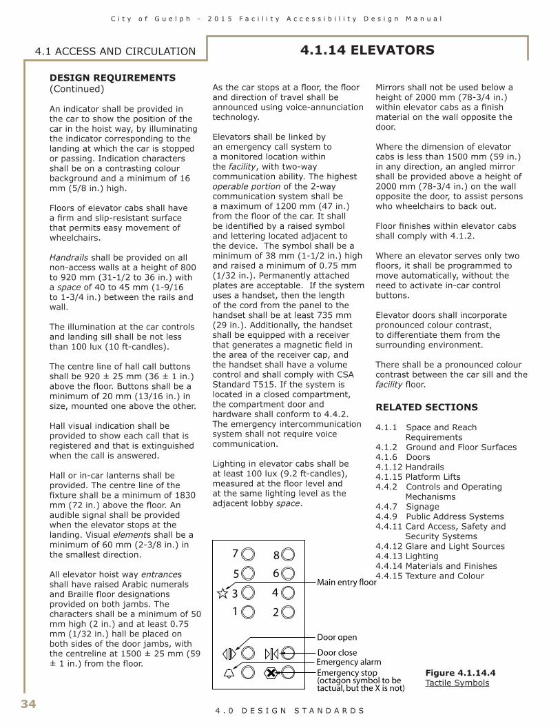
34
C i t y o f G u e l p h - 2 0 1 5 F a c i l i t y A c c e s s i b i l i t y D e s i g n M a n u a l
4 . 0 D E S I G N S T A N D A R D S
DESIGN REQUIREMENTS(Continued)
An indicator shall be provided in the car to show the position of the car in the hoist way, by illuminating the indicator corresponding to the landing at which the car is stopped or passing. Indication characters shall be on a contrasting colour background and a minimum of 16 mm (5/8 in.) high.
Floors of elevator cabs shall have a firm and slip-resistant surface that permits easy movement of wheelchairs.
Handrails shall be provided on all non-access walls at a height of 800 to 920 mm (31-1/2 to 36 in.) with a space of 40 to 45 mm (1-9/16 to 1-3/4 in.) between the rails and wall.
The illumination at the car controls and landing sill shall be not less than 100 lux (10 ft-candles).
The centre line of hall call buttons shall be 920 ± 25 mm (36 ± 1 in.) above the floor. Buttons shall be a minimum of 20 mm (13/16 in.) in size, mounted one above the other.
Hall visual indication shall be provided to show each call that is registered and that is extinguished when the call is answered.
Hall or in-car lanterns shall be provided. The centre line of the fixture shall be a minimum of 1830 mm (72 in.) above the floor. An audible signal shall be provided when the elevator stops at the landing. Visual elements shall be a minimum of 60 mm (2-3/8 in.) in the smallest direction.
All elevator hoist way entrances shall have raised Arabic numerals and Braille floor designations provided on both jambs. The characters shall be a minimum of 50 mm high (2 in.) and at least 0.75 mm (1/32 in.) hall be placed on both sides of the door jambs, with the centreline at 1500 ± 25 mm (59 ± 1 in.) from the floor.
As the car stops at a floor, the floor and direction of travel shall be announced using voice-annunciation technology.
Elevators shall be linked by an emergency call system to a monitored location within the facility, with two-way communication ability. The highest operable portion of the 2-way communication system shall be a maximum of 1200 mm (47 in.) from the floor of the car. It shall be identified by a raised symbol and lettering located adjacent to the device. The symbol shall be a minimum of 38 mm (1-1/2 in.) high and raised a minimum of 0.75 mm (1/32 in.). Permanently attached plates are acceptable. If the system uses a handset, then the length of the cord from the panel to the handset shall be at least 735 mm (29 in.). Additionally, the handset shall be equipped with a receiver that generates a magnetic field in the area of the receiver cap, and the handset shall have a volume control and shall comply with CSA Standard T515. If the system is located in a closed compartment, the compartment door and hardware shall conform to 4.4.2. The emergency intercommunication system shall not require voice communication.
Lighting in elevator cabs shall be at least 100 lux (9.2 ft-candles), measured at the floor level and at the same lighting level as the adjacent lobby space.
Mirrors shall not be used below a height of 2000 mm (78-3/4 in.) within elevator cabs as a finish material on the wall opposite the door.
Where the dimension of elevator cabs is less than 1500 mm (59 in.) in any direction, an angled mirror shall be provided above a height of 2000 mm (78-3/4 in.) on the wall opposite the door, to assist persons who wheelchairs to back out.
Floor finishes within elevator cabs shall comply with 4.1.2.
Where an elevator serves only two floors, it shall be programmed to move automatically, without the need to activate in-car control buttons.
Elevator doors shall incorporate pronounced colour contrast, to differentiate them from the surrounding environment.
There shall be a pronounced colour contrast between the car sill and the facility floor.
RELATED SECTIONS
4.1.1 Space and Reach Requirements
4.1.2 Ground and Floor Surfaces4.1.6 Doors4.1.12 Handrails4.1.15 Platform Lifts4.4.2 Controls and Operating
Mechanisms4.4.7 Signage4.4.9 Public Address Systems4.4.11 Card Access, Safety and
Security Systems4.4.12 Glare and Light Sources4.4.13 Lighting4.4.14 Materials and Finishes4.4.15 Texture and Colour
2
3 4
5 6
7 8
1
Main entry floor
Door open
Emergency alarmDoor close
Emergency stop (octagon symbol to betactual, but the X is not)
Figure 4.1.14.4Tactile Symbols
4.1 ACCESS AND CIRCULATION 4.1.14 ELEVATORS

C i t y o f G u e l p h - 2 0 1 5 F a c i l i t y A c c e s s i b i l i t y D e s i g n M a n u a l
35 4 . 0 D E S I G N S T A N D A R D S
4.1.15 PLATFORM LIFTS
RATIONALE
Platform lifts are typical in retrofit applications. Elevators that are used by all facility users are preferred to platform lifts which tend to segregate persons with disabilities and limit space at entrance and stair locations. Furthermore, independent access is often compromised, as platform lifts are often controlled by key operation. Whenever possible, grading or integrated elevator access should be incorporated to avoid the use of lifts.
If there are no suitable alternatives, lifts must be selected to permit the spatial requirement of larger mobility devices such as scooters.
APPLICATION
Accessible platform lifts shall comply with this section.
Platform lifts may only be used in lieu of an elevator or ramp where allowable under 4.1.14. Exception: Where it is technically infeasible to install an elevator or other accessible means of change of level.
DESIGN REQUIREMENTS
Accessible platform lifts shall
• be on an accessible route complying with 4.1.4;
• be identified with signage complying with applicable provisions of 4.4.7;
• comply with CSA standard CAN/CSA B355 (latest edition); and
• facilitate unassisted entry, operation, and exit from the lift.
The platform size shall be no less than 915 x 1525 mm (36 x 60 in.).
The doors to the platform lift shall comply with 4.1.6.
Controls and operating mechanisms shall comply with 4.4.2.
Platform lifts shall be linked by an emergency call system to a monitored location within the facility, with two-way communication ability. The highest operable portion of the two-way communication system shall be a maximum of 1200 mm (47 in.) from the floor of the car. If the system uses a handset, then the length of the cord from the panel to the
handset shall be at least 735 mm (29 in.). If the system is located in a closed compartment, the compartment door and hardware shall conform to 4.4.2.
Floor finishes within platform lifts shall comply with 4.1.2 and 4.4.14.
RELATED SECTIONS
4.1.1 Space and Reach Requirements
4.1.2 Ground and Floor Surfaces4.1.6 Doors4.1.12 Handrails4.1.14 Elevators4.4.2 Controls and Operating
Mechanisms4.4.7 Signage4.4.9 Public Address Systems4.4.11 Card Access, Safety and
Security Systems4.4.12 Glare and Light Sources4.4.13 Lighting4.4.14 Materials and Finishes4.4.15 Texture and Colour
Figure 4.1.15.1Vertical Platform Lift
Figure 4.1.15.2Inclined Platform Stair-Lift
4.1 ACCESS AND CIRCULATION

36
C i t y o f G u e l p h - 2 0 1 5 F a c i l i t y A c c e s s i b i l i t y D e s i g n M a n u a l
4 . 0 D E S I G N S T A N D A R D S
4.2.1 TOILET AND BATHING FACILITIES4.2 WASHROOM FACILITIES
RATIONALE
As an integral feature of a facility, washroom facilities should accommodate the range of people that will use the space. In some cases, a person with a disability may require assistance to use toilet and bathing facilities. Where the individual providing assistance is of the opposite gender then typical gender-specific washrooms are awkward and a universal washroom is preferred.
Circumstances such as wet surfaces and the act of transferring between toilet and wheelchair can make bathrooms accident-prone areas. Because of the risk of accidents, design decisions such as door swings have safety implications. An individual falling in a bathroom with a door that swings inward could prevent his or her own rescuers from opening the door. Due to the risk of accidents, bathrooms are prime locations for emergency call switches - consider also related response procedures. The appropriate design of all features will increase the usability and safety of the space.
Signs that used to identify washrooms should consider the needs of a variety of users. For children or someone who cannot read text, a symbol is preferred. A person with a visual impairment would also benefit from accessible signage. Features such as colour-contrasting doorframes and door hardware will also increase accessibility.
APPLICATION
Where toilet facilities are provided, each public or common use toilet facility shall comply with this section. Other toilet rooms provided for the use of occupants of specific spaces (i.e., a private toilet room for the occupant of a private office) shall be adaptable.
In a retrofit situation where it is technically infeasible to make existing public or common use toilet facilities accessible, the installation of at least one universal washroom
complying with 4.2.7 per floor, located in the same area as existing toilet facilities, will be permitted in lieu of modifying existing toilet facilities to be accessible.
In addition to any accessible public or common use toilets, at least one universal washroom complying with 4.2.7 shall be provided in a public area of all public buildings.
In addition to any accessible public or common use toilets, at least one universal washroom complying with 4.2.7 shall be provided on every floor in assembly buildings where the floor incorporates common or public use washroom containing four or more toilet and/or urinal fixtures.
The minimum number of universal washrooms per building shall be as shown on Table 4.2.1.
If universal washrooms are not visible from the common or public use washrooms, directional signage complying with 4.4.7 shall be provided.
If bathing facilities are provided on a site, then each such public or common use bathing facility shall comply with this section.
(23-5/8)
(18)
(18-
7/8)
1600 min *
1370
min
(72)
(
72)
(
54)
Clear space
Clear space
480
max
460 min
(18-1/8 to 18-7/8)
460-480
NOTE: In a retrofit situation where it is technically infeasible to provide the required clearances, the dimension marked with an * may be reduced to 1525 mm (60 in.).
1370
min
600 min
(63)
(54)
1830 min*
1830
min
*
180-degree turning space
920 min (36)
920 min (36)
(
60)
1525
min
900 min (35) Clear opening
(36)920 min
Figure 4.2.1.1Washroom Dimensions
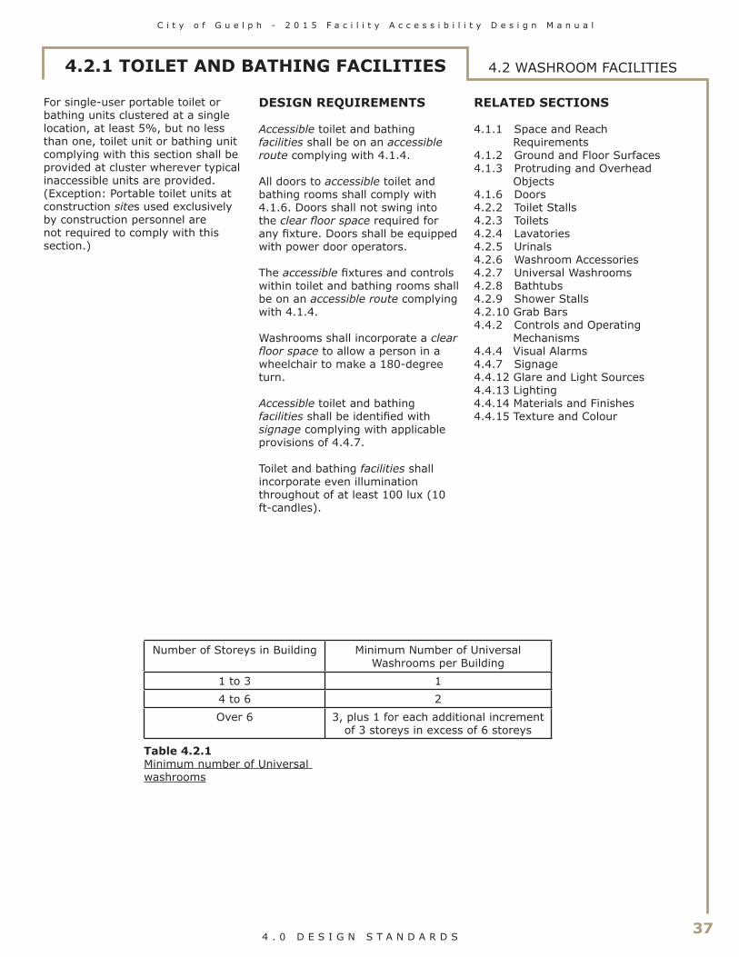
C i t y o f G u e l p h - 2 0 1 5 F a c i l i t y A c c e s s i b i l i t y D e s i g n M a n u a l
37 4 . 0 D E S I G N S T A N D A R D S
4.2.1 TOILET AND BATHING FACILITIES 4.2 WASHROOM FACILITIES
For single-user portable toilet or bathing units clustered at a single location, at least 5%, but no less than one, toilet unit or bathing unit complying with this section shall be provided at cluster wherever typical inaccessible units are provided. (Exception: Portable toilet units at construction sites used exclusively by construction personnel are not required to comply with this section.)
DESIGN REQUIREMENTS
Accessible toilet and bathing facilities shall be on an accessible route complying with 4.1.4.
All doors to accessible toilet and bathing rooms shall comply with 4.1.6. Doors shall not swing into the clear floor space required for any fixture. Doors shall be equipped with power door operators.
The accessible fixtures and controls within toilet and bathing rooms shall be on an accessible route complying with 4.1.4.
Washrooms shall incorporate a clear floor space to allow a person in a wheelchair to make a 180-degree turn.
Accessible toilet and bathing facilities shall be identified with signage complying with applicable provisions of 4.4.7.
Toilet and bathing facilities shall incorporate even illumination throughout of at least 100 lux (10 ft-candles).
RELATED SECTIONS
4.1.1 Space and Reach Requirements
4.1.2 Ground and Floor Surfaces4.1.3 Protruding and Overhead
Objects4.1.6 Doors4.2.2 Toilet Stalls4.2.3 Toilets4.2.4 Lavatories4.2.5 Urinals4.2.6 Washroom Accessories4.2.7 Universal Washrooms4.2.8 Bathtubs4.2.9 Shower Stalls4.2.10 Grab Bars4.4.2 Controls and Operating
Mechanisms4.4.4 Visual Alarms4.4.7 Signage4.4.12 Glare and Light Sources4.4.13 Lighting4.4.14 Materials and Finishes4.4.15 Texture and Colour
Number of Storeys in Building Minimum Number of Universal Washrooms per Building
1 to 3 14 to 6 2Over 6 3, plus 1 for each additional increment
of 3 storeys in excess of 6 storeys
Table 4.2.1Minimum number of Universal washrooms

38
C i t y o f G u e l p h - 2 0 1 5 F a c i l i t y A c c e s s i b i l i t y D e s i g n M a n u a l
4 . 0 D E S I G N S T A N D A R D S
RATIONALE
Manoeuvrability of a wheelchair or scooter is a principal consideration in the design of an accessible stall. The increased size of the stall is required to ensure there is sufficient space to facilitate the proper placement of a wheelchair or scooter to accommodate a transfer onto the toilet fixture. Not only is space required for the mobility equipment but there may also be instances where an individual requires assistance and the stall will have to accommodate a second person.
Door swings are normally outward for safety reasons and space considerations, but this makes it difficult to close the door once inside. A handle mounted part way along the door makes it easier for someone to close the door behind them.
Minimum requirements for non-accessible toilet stalls are included to ensure that persons who do not use wheelchairs or scooter can be adequately accommodated within any toilet stall. Universal features include accessible hardware and minimum stall widths to accommodate persons of large stature.
APPLICATION
If toilet stalls are provided in a toilet or bathing facility, then the number of accessible toilet stalls designated to accommodate persons with disabilies shall comply with Table 4.2.2.
4.2.2 TOILET STALLS4.2 WASHROOM FACILITIES
Figure 4.2.2.1Accessible Toilet Stall
Table 4.2.2Number of Accessible Toilet Stalls
1830 min *(72)
1830 min
*
(72)
460 - 480
900 min
200-300(7-7/8 to 11-3/4)
50 mm (2 in.) collapsible coat hook1200 mm (47 in.) maxabove the floor
* Door Pull 140 mm (5-1/2 in.) min.
* Sliding latch
* Door Pull 140 mm (5-1/2 in.) min.on both sidesof door
(35)
clear opening
(18-1/8 to18-7/8)
1500 (59) diameterclear turn circle
* mounting height for door hardware is to be between 900 and 1100 mm (35 - 43-1/4 in.) above the floor.
# of toilet stalls within the washroom1 - 55 - 1617 - 2021 - 30Over 30
Required # of accessible toilet stalls12345 plus 1 for each additional increment of 10

C i t y o f G u e l p h - 2 0 1 5 F a c i l i t y A c c e s s i b i l i t y D e s i g n M a n u a l
39 4 . 0 D E S I G N S T A N D A R D S
Accessible toilet stalls shall comply with this section.
Where a washroom is provided in a storey that does not have a barrier-free path of travel, the washroom shall have: • an accessible water closet that
complies with 4.2.3;• where more than one urinal is
provided, at least one urinal that complies with section 4.2.5;
• at least one accessible lavatory that complies with section 4.2.4; and
• at least one ambulatory water closet stall.
DESIGN REQUIREMENTS
Accessible toilet stalls shall
• be on an accessible route complying with 4.1.4.
• have internal dimensions at least 1830 x 1830 mm (72 x 72 in.).;
• have a clear turning space within the stall of at least 1500 mm (59 in.) in diameter;
• have a toilet complying with 4.2.3; and
• be equipped with a collapsible coat hook mounted not more than 1200 mm (47 in.) from the floor on a side wall and projecting not more than 50 mm (2 in.) from the wall.
Every barrier-free water closet stall in a washroom shall have a clearance of at least 1700 mm (67 in.) between the outside of the stall face and the face of an in-swinging washroom door, and 1400 mm (55-1/8 in.) between the outside of the stall face and any wall-mounted fixture or other obstruction.
Toilet stall doors shall
• be capable of being latched from the inside with a mechanism that is operable using a closed fist;
• requires a force of not more than 22 N (4.9 lb.) to activate (e.g., sliding bolt or lever); and can be opened from the outside in an emergency situation.
• provide a clear opening of at least 900 mm (35 in.) with the door in the open position. In a retrofit situation where it's technically infeasible to provide the required clear opening, the clear opening may be reduced to 860 mm (34 in.);
• swing outward, unless additional clear space of at least 820 mm x 1440 mm (32-1/4 in. x 56-3/4 in.) is provided within the stall, outwith the arc of the door swing;
• be aligned with the clear floor space adjacent to the toilet fixture, where applicable;
• be equipped with gravity hinges so that the door closes automatically;
• be provided with a “D”-type contrasting-coloured door pull, at least 140 mm (5-1/2 in.) long, on the inside of an out-swinging door, located so that the centre line is between 200 and 300 mm (7-7/8 in. and 11-3/4 in.) from the hinged side of the door, and 800-1000 (31-1/2 - 39-3/8 in.) above floor height
• be provided with a “D”-type contrasting-coloured door pull at least 140 mm (5-1/2 in.) long, on both sides of the door, located near the latch at a height no less than 900 mm (35 in.) and no more than 1100 mm (43-1/4 in.).
The transfer space adjacent to the toilet fixture, as required by 4.2.3, shall be clear of obstructions (such as garbage bins or baby change tables).
Designated ambulatory water closet stalls shall
• be at least 1525 mm (60 in.) deep and 920 mm (36 in.) wide;
• have a toilet fixture complying with 4.2.3 and located so that its centre line is centred between the partition walls;
• be equipped with L-shaped grab bars on both side of the toilet in compliance with 4.2.3 and 4.2.10.
All other toilet stalls within a facility shall be minimum 920 mm (36 in.) wide by 1525 mm (60 in.) long, and shall incorporate door-locking mechanisms in compliance with this section.
Toilet stall partitions and doors shall be colour-contrasted with the surrounding environment.
Where more than one accessible toilet stall is provided within a washroom, the stalls shall be configured with the transfer space (i.e., the open space beside the toilet) on opposite sides of the toilet fixtures.
RELATED SECTIONS
4.1.1 Space and Reach Requirements
4.1.3 Protruding and Overhead Objects
4.1.6 Doors4.2.3 Toilets4.2.6 Washroom Accessories4.2.10 Grab Bars4.4.2 Controls and Operating
Mechanisms4.4.13 Lighting4.4.15 Texture and Colour
4.2.2 TOILET STALLS 4.2 WASHROOM FACILITIES

40
C i t y o f G u e l p h - 2 0 1 5 F a c i l i t y A c c e s s i b i l i t y D e s i g n M a n u a l
4 . 0 D E S I G N S T A N D A R D S
4.2.3 TOILETS4.2 WASHROOM FACILITIES
RATIONALE
Automatic flush controls are preferred. If flushing mechanisms are not automated, then consideration must be given to the ability to reach a switch and the hand strength or dexterity to operate it. Lever style handles on the transfer side of the toilet facilitate this. Appropriate placement of grab bars makes sitting and standing or transfers between toilet and wheelchair safer.
APPLICATION
Accessible toilets shall comply with this section. Wall-mounted toilets are preferred.
DESIGN REQUIREMENTS
Toilet fixtures shall have
• the top of the seat between 430 and 460 mm (17 and 18-1/8 in.) from the floor;
• no spring-activated seat;• a back support where there is
no seat lid or tank; and• the tank top securely attached.
Toilets shall be located 460 to 480 mm (18-1/8 to 18-7/8 in.) from the centre line to the adjacent wall with a clear transfer space on the other side of the toilet fixture, or with clear transfer space on each side of the water closet.
Clear transfer space shall be 900 mm (35-1/2 in.) wide and 1500 mm (59 in.) deep.
The clear transfer space shall be clear of obstructions (such as garbage bins or baby change tables).
Toilet flush controls shall be
• hand-operated on the transfer side of the toilet; or
• be electronically automatically controlled. Where automatically controlled, sensors not to be disrupted by seat lid or backrest.
Hand-operated flush controls shall comply with 4.4.2.
Toilets shall be equipped with grab bars that shall
• comply with 4.2.10;• be L-shaped where a water
closet is located 460 to 480 mm (18-1/8 to 18-7/8 in.) from the adjacent wall, with 750 mm (29-1/2 in.) long horizontal and vertical components mounted with the horizontal component 750 mm (29-1/2 in.) above the floor and the vertical component 150 mm (5-7/8 in.) in front of the toilet bowl; and
• be at least 600 mm (23-5/8 in.) in length, mounted horizontally on the wall behind the toilet, from 840 mm (33 in.) to 920 mm (36 in.) above the floor, and, where the water closet has a water tank, be mounted minimum 150 mm (5-7/8 in.) above the tank.
• be of a fold-down type at least 760 mm (30 in.) in length at the open side of the toilet where a water closet is located 460 to 480 mm (18-1/8 to 18-7/8 in.) from the adjacent wall, or on each side of the water closet
where transfer space is provided on each side, mounted 390 - 410 mm (15-3/8 - 16-1/8 in.) from the centre line of the water closet and with the horizontal component 750 mm (24-3/4 in.) above the finished floor, requiring a maximum force of 22.2 N to pull it down. Fold-down grab bars are permitted to encroach into the clear turning space or a clear transfer space.
When a toilet-paper dispenser is provided, the dispenser shall be
• wall mounted;• located below the grab bar;• in line with or not more than
300 mm (11-3/4 in.) in front of the toilet seat;
• not less than 600 mm (23-5/8 in.) above the floor; and
• contrasting in colour to the wall.
RELATED SECTIONS
4.1.1 Space and Reach Requirements
4.2.2 Toilet Stalls4.2.10 Grab Bars4.4.2 Controls and Operating
Mechanisms4.4.13 Lighting4.4.15 Texture and Colour
4
30-4
60
(29
1/2
)
750
(5-7
/8) Grab Bar
1
50 m
in
Grab Bar
Toilet-paper dispenser
60 (2-3/8) min clearance to grab bar
300 max (11-3/4)
6
00 m
in
(23-
5/8)
(33
- 36)
840
- 920
(30)760 min
(30)
760
min
(5-7/8) 150 min
(17
- 18-
1/8)
Figure 4.2.3.1Grab Bar Configuration

C i t y o f G u e l p h - 2 0 1 5 F a c i l i t y A c c e s s i b i l i t y D e s i g n M a n u a l
41 4 . 0 D E S I G N S T A N D A R D S
4.2.4 LAVATORIES 4.2 WASHROOM FACILITIES
RATIONALE
The accessibility of lavatories will be greatly influenced by their operating mechanisms. While faucets with remote-eye technology might initially confuse some individuals, their ease of use is notable. Individuals with hand strength or dexterity difficulties can use lever-style handles. For an individual in a wheelchair, a lower counter height and clearance for knees under the counter would be required. This lower counter may also serve children. The insulation of pipes protects an individual using a wheelchair whose legs may come into contact with hot water pipes. This is particularly important when a disability impairs sensation such that the individual would not sense that their legs were being burned. The combination of shallow sinks and higher water pressures can cause unacceptable splashing at lavatories.
APPLICATION
All lavatories shall comply with this section. In a retrofit situation where it is technically infeasible to have all lavatories comply with this section, at least one lavatory in each accessible washroom shall comply.
DESIGN REQUIREMENTS
Lavatories shall
• be on an accessible route complying with 4.1.4;
• be mounted so that the minimum distance between the centre line of the fixture and the side wall is 460 mm (18-1/8 in.);
• have the top located between 820 mm (32-1/4 in.) and 840 mm (33 in.) from the floor;
• have a knee space of at least • 920 mm (36 in.) wide;• 735 mm (29 in.) high at the
front edge;• 685 mm high (27 in.) at a
point 205 mm (8-1/8 in.) back from the front edge; and
• 350 mm (13-3/4 in.) high over the distance from a point 300 mm (11-3/4 in.) back from the front edge to the wall;
• have a minimum clear floor space 920 mm wide (36 in.) and 1370 mm (54 in.) deep, of which a maximum of 480 mm (18-7/8 in.) in depth may be under the lavatory;
• have hot water and drain pipes insulated if they abut the clearances noted above, or have the water temperature limited to a maximum of 43 degrees Celsius (100 degrees F); and
• have soap and towel dispensers that are• located to be accessible
to persons in a wheelchair (i.e., not having to reach over the lavatory to access the devices);
• located not more than 610 mm (24 in.) measured horizontally, from the edge of the lavatory;
• located so that the dispensing height is not more than 1200 mm (47 in.) above the floor;
• colour-contrasted from the surrounding environment; and
• in compliance with 4.4.2.
Faucets and other controls shall• be in compliance with 4.4.2;• have lever type handles without
spring loading, or operate automatically; and
• be located so that the distance from the centre line of the faucet to the edge of the basin, or where the basin is mounted in a vanity, to the front edge of the vanity is not more than 485 mm (19-1/8 in.).
The front apron of a vanity shall have a minimum clearance of 920 mm (36 in.) wide by 735 mm (29 in.) high.
Shelves or other projections above lavatories shall be located so they will not present a hazard to persons with a visual disability. It shall be located not more than 200 mm (7-7/8 in.) above the top of the lavatory and not more than 1100 mm (43-1/4 in.) above the finished floor, and project not more than 100 mm (4 in.) from the wall.
Where mirrors are provided at lavatories or vanity units, they shall comply with 4.2.6.
RELATED SECTIONS
4.1.1 Space and Reach Requirements
4.4.2 Controls and Operating Mechanisms
4.4.13 Lighting4.4.15 Texture and Colour
1000
max
(or u
se t
ilt m
irro
r)
(32
1/4
- 33)
(29)
480 max
300
350
min
205
Mirror
Single/double lever handle or infra-red faucet
1370 min (54) clear space
(39)
820
- 84
0
735
(13-
3/4)
(8 1/8)
(11-3/4)
(18-7/8)
(27)
68
5
Figure 4.2.4.1Lavatory Criteria

42
C i t y o f G u e l p h - 2 0 1 5 F a c i l i t y A c c e s s i b i l i t y D e s i g n M a n u a l
4 . 0 D E S I G N S T A N D A R D S
4.2.5 URINALS4.2 WASHROOM FACILITIES
RATIONALE
A clear floor space is required in front of urinals to manoeuvre a mobility device. The provision of grab bars may assist an individual in rising from the chair and to steady themselves. Floor-mounted urinals accommodate children and persons of short stature as well as making it easier to drain personal care devices. Flush controls should be lever or automatic (preferred). Strong colour contrasts will assist persons with a visual impairment.
APPLICATION
Where urinals are provided in an accessible toilet or bathing facility, at least one shall comply with this section.
DESIGN REQUIREMENTS
Urinals shall be
• wall-mounted with an elongated rim located with the rim no higher than 430 mm (17 in.) from the finished floor: or
• floor-mounted, with the rim level at the finished floor.
A urinal shall have no step in front.
Urinals shall be at least 345 mm (13-1/2 in.) deep, measured from the outer face of the urinal rim to the back of the fixture.
A clear floor space of 760 mm x 1370 mm (30 in. x 54 in.) shall be provided in front of the urinal to allow for a forward approach. This clear space shall adjoin or overlap an accessible route and shall comply with 4.1.1.
Where privacy screens are provided
• there shall be at least 920 mm (36 in.) of clearance between them; and
• they shall incorporate a pronounced colour contrast, to differentiate them from the surrounding environment, with a vertical outer edge that contrasts with the screen and the surrounding environment.
The urinal shall have grab bars installed on each side that
• are vertically mounted• are not less than 600 mm (23-
5/8 in.) long• have their lower end located
600 - 650 mm (23-5/8 - 25-1/2 in.) above the floor
• are located 380 mm (15 in.) from the centre line of the urinal; and
• comply with 4.2.10
Flush controls shall be operable using a closed fist or automatic, mounted at no more than 1120 mm (44 in.) above the finished floor, and shall comply with 4.4.2.
RELATED SECTIONS
4.1.1 Space and Reach Requirements
4.4.2 Controls and Operating Mechanisms
4.4.13 Lighting4.4.15 Texture and Colour
Lever typeflush valve
(23-
5/8
-
25-
1/2)
600
-650
600
min
(23-
5/8)
112
0 m
ax (44)
430 max to rim(17)
Grab bars
Recommendedprivacy screen
(36)920 min
380 max (15)
345 min
(15)
(13-1/2)
380 max
Figure 4.2.5.1Urinal
Figure 4.2.5.2Urinal
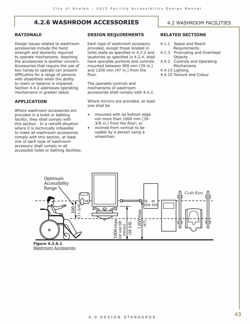
C i t y o f G u e l p h - 2 0 1 5 F a c i l i t y A c c e s s i b i l i t y D e s i g n M a n u a l
43 4 . 0 D E S I G N S T A N D A R D S
4.2.6 WASHROOM ACCESSORIES 4.2 WASHROOM FACILITIES
RATIONALE
Design issues related to washroom accessories include the hand strength and dexterity required to operate mechanisms. Reaching the accessories is another concern. Accessories that require the use of two hands to operate can present difficulties for a range of persons with disabilities when the ability to reach or balance is impaired. Section 4.4.2 addresses operating mechanisms in greater detail.
APPLICATION
Where washroom accessories are provided in a toilet or bathing facility, they shall comply with this section. In a retrofit situation where it is technically infeasible to make all washroom accessories comply with this section, at least one of each type of washroom accessory shall comply in all accessible toilet or bathing facilities.
OptimumAccessibilityRange
1000
max
(or u
se t
ilt
m
irro
r)
(38
3/8)
1200
max
(47)
300
(11-
3/4)
DESIGN REQUIREMENTS
Each type of washroom accessory provided, except those located in toilet stalls as specified in 4.2.2 and lavatories as specified in 4.2.4, shall have operable portions and controls mounted between 900 mm (35 in.) and 1200 mm (47 in.) from the floor.
The operable controls and mechanisms of washroom accessories shall comply with 4.4.2. Where mirrors are provided, at least one shall be
• mounted with its bottom edge not more than 1000 mm (39-3/8 in.) from the floor; or
• inclined from vertical to be usable by a person using a wheelchair.
RELATED SECTIONS
4.1.1 Space and Reach Requirements
4.1.3 Protruding and Overhead Objects
4.4.2 Controls and Operating Mechanisms
4.4.13 Lighting4.4.15 Texture and Colour
Figure 4.2.6.1Washroom Accessories

44
C i t y o f G u e l p h - 2 0 1 5 F a c i l i t y A c c e s s i b i l i t y D e s i g n M a n u a l
4 . 0 D E S I G N S T A N D A R D S
810
min
(32)
(18-
1/8
to18
-7/8
)
Change table
Collapsiblecoat hook
Fold-downgrab bar
2000 (78) min diameterturn space
Emergency call switch
(18)1830 min (72)
460
-480
460 min
If inswinging door, adjust washroomsize/configuration so that door swingdoes not interfere with turning space
(18-
1/8
to18
-7/8
)
460
-480
Figure 4.2.7.1Universal Washroom
RATIONALE
The provision of a separate universal washroom is advantageous in a number of instances. For an individual using a wheelchair, the extra space provided with a separate washroom is preferred to an accessible stall. Should an individual require an attendant to assist them in the washroom then the complication of a woman entering a men’s washroom or vice versa is avoided. This same scenario would apply to a parent with a young child of a different gender. In the event of an accident or fall by a single individual in this form of washroom, an emergency call switch and a means of unlocking the door from the outside are important safety features.
APPLICATION
Universal washrooms shall be provided as required by 4.2.1.
Universal washrooms shall comply with this section.
DESIGN REQUIREMENTS
Universal washrooms shall be on an accessible route complying with 4.1.4.
Universal washrooms shall be identified with signage complying with applicable provisions of 4.4.7.
Universal washrooms shall
• be designed to permit a wheelchair to turn in an open space that has a diameter of not less than 2000 mm (78-3/4 in.);
• have no internal dimension between walls that is less than 1700 mm (67 in.);
• be equipped with a door that• complies with 4.1.6
including a power door operator;
• is capable of being locked from the inside with one hand and being released from the outside in case of emergency;
• has graspable latch operating and locking mechanisms located not less than 900 mm (35 in.) and not more than 1000 mm (39-3/8 in.) above the floor;
• if in-swinging, shall not swing across the turning space and be equipped with hinges that allow for quick removal in an emergency;
• if outward swinging, a door pull not less than 140 mm (5-1/2 in.) long located on the inside so that its midpoint is 200 - 300 mm (7-7/8 - 11-3/4 in.) from the latch side of the door and 900 - 1000 mm (35 - 39-3/8 in.) above the finished floor; and
• a door closer or gravity hinges so that the door closes automatically.
• be provided with a lavatory conforming to 4.2.4;
• be equipped with a toilet conforming to 4.2.3
4.2.7 UNIVERSAL WASHROOMS4.2 WASHROOM FACILITIES

C i t y o f G u e l p h - 2 0 1 5 F a c i l i t y A c c e s s i b i l i t y D e s i g n M a n u a l
45 4 . 0 D E S I G N S T A N D A R D S
4.2.7 UNIVERSAL WASHROOMS 4.2 WASHROOM FACILITIES
• be equipped with grab bars conforming to 4.2.10;
• be equipped with a fold-down grab bar at least 760 mm (30 in.) in length at the open side of the toilet, mounted 420 - 440 mm (16-1/2 - 17-3/8 in.) from the centre line of the toilet and 750 mm - 810 mm (24-3/4 - 27-1/8 in.) above the floor;
• have fixture clearances conforming to 4.2.3 and 4.2.4;
• be designed to permit a wheelchair to back into the required clear space beside the toilet fixture;
• be equipped with • a collapsible coat hook
mounted not more than 1200 mm (47 in.) from the floor on a side wall and projecting not more than 50 mm (2 in.) from the wall;
• a mirror and washroom accessories complying with 4.2.6;
• a shelf located not more than 1200 mm (47 in.) above the finished floor; and
• lighting controlled by a motion sensor.
A universal washroom shall have an emergency call system that consists of audible and visual signal devices inside and outside of the washroom that are activated by a control device inside the washroom, and an emergency sign that contains the words IN THE EVENT OF AN EMERGENCY PUSH EMERGENCY BUTTON AND AUDIBLE AND VISUAL SIGNAL WILL ACTIVATE in letters at least 25 mm (1 in.) high with a 5mm ( in.) stroke and that is posted above the emergency button.
Where universal washrooms are provided in assembly buildings, such as recreation centres, the washroom shall incorporate an emergency call system linked to a central monitoring location (e.g., office or switchboard).
Universal washrooms shall incorporate a change table
• that is at least 810 mm (32 in.) wide by 1830 (72 in.) long;
• that, when fully loaded, has a surface height above the finished floor that is adjustable from between 450 - 500 mm (18 - 19-5/8 in.) at the low range to between 850 - 900 mm (33 - 35 in.) at the high range;
• which incorporates an adjacent clear floor space not less than 760 mm (30 in.) by 1500 mm (59 in.) long;
• that is equipped with a grab bar that complies with 4.2.10 and be L-shaped with 760 mm (30 in.) long horizontal and vertical components mounted with the horizontal component 300 mm (12 in.) above the surface of the table and the vertical component 150 mm (5-7/8 in.) in front of the table;
• designed to carry a minimum load of 1.33 kN (300 lbs);
• which incorporates signage indicating its weight capacity
• located on an accessible route in compliance with 4.1.4;
• if of the fold-down type, have no operable portions higher than 1200 mm (47 in.); and
• that is installed so that it does not encroach into a clear transfer space.
RELATED SECTIONS
4.1.1 Space and Reach Requirements
4.1.2 Ground and Floor Surfaces4.1.3 Protruding and Overhead
Objects4.1.6 Doors4.2.3 Toilets4.2.4 Lavatories4.2.5 Urinals4.2.6 Washroom Accessories4.2.10 Grab Bars4.4.2 Controls and Operating
Mechanisms4.4.7 Signage4.4.11 Card Access, Safety and
Security Systems4.4.12 Glare and Light Sources4.4.13 Lighting4.4.14 Materials and Finishes4.4.15 Texture and Colour

46
C i t y o f G u e l p h - 2 0 1 5 F a c i l i t y A c c e s s i b i l i t y D e s i g n M a n u a l
4 . 0 D E S I G N S T A N D A R D S
4.2.8 BATHTUBS4.2 WASHROOM FACILITIES
RATIONALE
Bathtubs can present a slipping hazard. Slip-resistant surfaces are an important feature and will benefit any individual, including those with disabilities. Grab bars also provide stability. Operating systems are subject to limitations in hand strength, dexterity and reach.
APPLICATION
Where bathtubs are provided, all bathtubs shall comply with this section. In a retrofit situation where it is technically infeasible to have all bathtubs comply with this section, at least 10%, but never less than one, in each bathing area shall comply with this section.
Individual bathtubs that are provided for the use of patients or residents in buildings of Group B, Division 2 or 3 occupancy shall comply with this section.
DESIGN REQUIREMENTS
Accessible bathtubs shall be on an accessible route complying with 4.1.4.
Accessible bathtubs shall have
• a clear floor space at least 920 mm wide (36 in.) along the length of the bathtub;
• faucet handles of the lever type that are not spring-loaded, or are automatically operable;
• faucet handles that are located so as to be usable by a person seated in the bathtub;
• faucets and other controls mounted not more than 450 mm (17-3/4 in.) above the bathtub rim;
• a shower head complying with 4.2.9;
• unless the bathtub is freestanding, an L-shaped grab bar conforming to 4.2.10 mounted on the long wall• with each leg of the “L”
being at least 920 mm (36 in.) in length;
• with the legs of the “L” being separated by a 90 degrees;
• with the horizontal leg of the “L” being located 150 - 200 mm (5-7/8 - 7-7/8 in.) above and parallel to the rim of the bathtub; and
• with the vertical leg of the “L” being located 300 - 450 mm (11-3/4 - 17-3/4 in.) from the control end of the tub.
• controls equipped with a pressure-equalizing or thermostatic-mixing valve, operable from the seated position and in compliance with 4.4.2;
• soap holder(s) which can be reached from the seated position, ideally fully recessed; and
• unless the bathtub is freestanding, a grab bar conforming to 4.2.10 which is at least 1220 mm (48 in.) long, mounted vertically at the foot end of the tub adjacent to the clear floor space, with the lower
end 200 mm (7-7/8 in.) above the bathtub rim, mounted within 150 mm (5-7/8 in.) from the edge of the bathtub, measured horizontally.
Enclosures for bathtubs shall not
• obstruct controls;• interfere with a person
transferring from a wheelchair; or
• have tracks mounted on the bathtub rim.
RELATED SECTIONS
4.1.1 Space and Reach Requirements
4.2.6 Washroom Accessories4.2.10 Grab Bars4.4.2 Controls and Operating
Mechanisms4.4.13 Lighting4.4.15 Texture and Colour
300-450
1220
min
150
-200
920 min
Clear space
450max (17 3/4)
(11 3/4-17 3/4)
(48)
20
0(7
-7/8
)
(5-7
/8 -
7
-7/8
)
920
min
(3
6)
920 min (36)
(36)
150 max(5-7/8)
Figure 4.2.8.1Bathtub

C i t y o f G u e l p h - 2 0 1 5 F a c i l i t y A c c e s s i b i l i t y D e s i g n M a n u a l
47 4 . 0 D E S I G N S T A N D A R D S
4.2.9 SHOWER STALLS 4.2 WASHROOM FACILITIES
RATIONALE
Grab bars and non-slip materi-als are safety measures which will support any individual. Additional equipment such as a hand-held shower or bench, may be an asset to someone with a disability but also convenient for others. Equipment that contrasts in colour from the shower stall itself assists individuals with a visual impairment. Roll-in or curbless shower stalls eliminate the hazard of stepping over a threshold and are essential for persons with disabilities who use wheelchairs in the shower.
APPLICATION
Where shower stalls are provided, all shower stalls shall comply with this section. In a retrofit situation where it is technically infeasible to have all shower stalls comply with this section, if 1-7 shower stalls are provided in a group, at least 1 shower must comply, and if there are more than 7 showers provided in a group, 1 plus 1 for each additional increment of 7 showers in each bathing area shall comply with this section.
DESIGN REQUIREMENTS
Accessible shower stalls shall
• be on an accessible route complying with 4.1.4;
300 mm (11-3/4 in.) of its length is reachable from one side of the seat;
• have a vertical component at least 760 mm (30 in.) in length; and
• conform to 4.2.10;• be equipped with a vertical grab
bar on each end wall that:• is at least 760 mm (30 in.) in
length;• is mounted 80 - 120 mm
(3-1/8 - 4-3/4 in.) from the front edge, at a point 700 - 800 mm (27-1/2 - 31-1/2 in.) above the finished floor; and
• conforms to 4.2.10;• be equipped with a pressure-
equalizing or thermostatic-mixing valve in compliance with 4.4.2, located above the grab bar but no higher than 1000 mm (39-3/8 in.), maximum 685 mm (27 in.) from the seat wall;
• be equipped with a shower head with at least 1525 mm (60 in.) of flexible hose that can be used both as a fixed position shower head and as a hand held shower. The shower spray unit shall be reachable from the seated positions and have an on/off control. Exception: A non-adjustable, overhead-mounted shower head is permitted instead of a hand-held spray unit in facilities that are not long term care facilities or residential dwelling units; and
• have soap holder(s) which can be reached from the seated position, and are fully recessed.
Where the showerhead is mounted on a vertical bar, the bar shall be installed so as not to obstruct the use of the grab bar.
Enclosures for shower stalls shall not obstruct controls or obstruct transfer from wheelchairs onto shower seats. RELATED SECTIONS
4.1.1 Space and Reach Requirements
4.2.6 Washroom Accessories4.2.10 Grab Bars4.4.2 Controls and Operating
Mechanisms4.4.13 Lighting4.4.15 Texture and Colour
1525 min (60)
920 min
(36)
Bevelled threshold 6 max (1/4)
7
00 -
800
(27
1/2
- 31
1/2)
80-120(3-1/8 - 4-3/4)
760
min
(3
0)
450
920 min
850
max
.(3
3)
920 min
(36)
Clear space
Folding bench
Control valve max 1000 high
(17-
3/4)
685 max (27)
(36)
300 min (11-3/4)
(39-3/8)
Figure 4.2.9.1Shower Stall
• be at least 1525 mm (60 in.) in width and 920 mm (36 in.) in depth;
• have a clear floor space at the entrance to the shower of at least 920 mm (36 in.) in depth and the same width as the shower, except that fixtures are permitted to project into that space, provided they do not restrict access to the shower;
• have a slip-resistant floor surface;
• have no threshold, or a bevelled threshold not exceeding 6 mm (1/4 in.) above the finished floor;
• be equipped with a wall-mounted folding seat that is not spring-loaded, or make provisions for a portable seat that is
• 450 mm (17-3/4 in.) wide and 400 mm (15 in.) deep;
• mounted approximately 450 mm (17-3/4 in.) above the floor;
• designed to carry a minimum load of 1.33 kN (300 lbs.); and
• located so that the edge of the seat is within 500 mm (19-5/8 in.) of the shower controls;
• be equipped with a wall mounted continuous L-shaped grab bar that shall • be located between the
shower head and the controls;• have a horizontal component
at least 920 mm (36 in.) in length;
• be mounted horizontally approximately 850 mm (33 in.) above the floor;
• have the horizontal component located on the wall so at least

48
C i t y o f G u e l p h - 2 0 1 5 F a c i l i t y A c c e s s i b i l i t y D e s i g n M a n u a l
4 . 0 D E S I G N S T A N D A R D S
4.2.10 GRAB BARS4.2 WASHROOM FACILITIES
RATIONALE
Grab bars are an important feature to those who require assistance in standing up, sitting down or stability while standing. Transferring between toilet and wheelchair may be another scenario where grab bars are utilized.
APPLICATION
Grab bars shall comply with this section.
DESIGN REQUIREMENTS
Grab bars shall
• be installed to resist a load of at least 1.3 kN (300 lb.), applied vertically or horizontally;
• be not less than 35 mm (1-3/8 in.) and not more than 40 mm (1-9/16 in.) in diameter;
• have a clearance of 50 mm (2 in.) from the wall;
• be free of any sharp or abrasive elements;
• be colour-contrasted with the surrounding environment; and
• have a slip-resistant surface.
Adjacent surfaces shall be free of any sharp or abrasive elements.
RELATED SECTIONS
4.1.1 Space and Reach Requirements
4.2.3 Toilets4.2.5 Urinals4.2.7 Universal Washrooms4.2.8 Bathtubs4.2.9 Shower Stalls4.4.13 Lighting4.4.15 Texture and Colour
(1-3/8 to1-9/16) (2)
Smooth wall finish
35-40 50
Figure 4.2.10.1Grab Bar

C i t y o f G u e l p h - 2 0 1 5 F a c i l i t y A c c e s s i b i l i t y D e s i g n M a n u a l
49 4 . 0 D E S I G N S T A N D A R D S
RATIONALE
Planning for the design of drinking fountains should consider the lim-ited height of children or persons using a wheelchair. In the same respect, there may be individuals who have difficulty bending who would require a higher fountain. The operating system should account for limited hand strength or dexter-ity. The placement of the fountain is also important. Fountains should be recessed, to avoid protruding into the path of travel, especially if they are wall mounted above the detect-able height of a cane.
APPLICATION
Where drinking fountains are provided on a floor, at least one shall be accessible and shall comply with this section.
Where only one drinking fountain is provided on a floor, it shall incorporate components that are
accessible to individuals who use wheelchairs in accordance with this section, as well as components that are accessible to persons who have difficulty stooping or bending.
Where more than one drinking fountain or water cooler is provided on a floor, at least 50% shall comply with this section.
DESIGN REQUIREMENTS
Accessible drinking fountains shall
• be located on an accessible route complying with 4.1.4;
• have a spout located near the front of the unit between 760 mm (30 in.) and 900 mm (35 in.) above the floor or ground surface;
• provide the water stream at a vertical angle of up to• 30 degrees where the spout
is located less than 75 mm (3 in.) from the front of the fountain; or
Figure 4.3.1.2Frontal Approach
Figure 4.3.1.1Parallel Approach
Figure 4.3.1.3Clearances
• 15 degrees where the spout is located not less than 75 mm (3 in.) and not more than 125 mm (5-7/8 in.) from the front of the fountain;
• have a spout that provides a water flow at least 100 mm (4 in.) high;
• be equipped with controls that are located on the front of the unit, or on both sides of the unit, easily operated from a wheelchair, using one hand, with a force of not more than 22 N (4.9 lb.), or be automatically operable; and
• be detectable by a cane at a level at or below 680 mm (26-1/2 in.) from the finished floor.
Cantilevered drinking fountains shall
• have a clear floor space of at least 810 mm (32 in.) by 1370 mm (54 in.);
• have a knee space between the bottom of the apron and the floor or ground of at least 810 mm (32 in.) wide, 500 mm (19-1/2 in.) deep and 735 mm (29 in.) high;
• have a toe space not less than 760 mm (30 in.) wide, and 350 mm (13-3/4 in.) high from a point 300 mm (11-3/4 in.) back from the front edge to the wall;
• be recessed or otherwise located out of the circulation route; and
• be mounted not more than 915 mm (36 in.) above the finished floor.
Freestanding or built-in fountains not having a knee space shall have a clear floor space at least 1370 mm (54 in.) wide by 760 mm (30 in.) deep in front of the unit.
RELATED SECTIONS
4.1.1 Space and Reach Requirements
4.1.2 Ground and Floor Surfaces4.1.3 Protruding and Overhead
Objects4.1.4 Accessible Routes, Paths and
Corridors4.4.13 Lighting4.4.14 Materials and Finishes4.4.15 Texture and Colour
4.3.1 DRINKING FOUNTAINS 4.3 OTHER AMENITIES
760-900 (30-35) to spout opening
(32)
(54)
Clear space
810 min
1370 min
Clear space
Angled alcovesallow more flexibility on parallel approach
760-900 (30-36) to spout opening
810 min (32)
1370 min
(5
4)
Clear space
(11-3/4)
Equipment permitted in shaded area
760
- 900
(3
0 - 3
5)
735
min
(29)
350
min
(13-
3/4)
300
500 (19-1/2)

50
C i t y o f G u e l p h - 2 0 1 5 F a c i l i t y A c c e s s i b i l i t y D e s i g n M a n u a l
4 . 0 D E S I G N S T A N D A R D S
4.3.2 VIEWING POSITIONS4.3 OTHER AMENITIES
RATIONALE
Designated viewing areas are required for individuals unable to use typical seating. Viewing areas need to provide adequate space to manoeuvre a mobility device as large as a scooter and should not be limited to one location. Designated companion seating should also be provided. Guards placed around a viewing area should not interfere with the line of sight of someone sitting in a wheelchair. A choice of locations and ticket price range should be available.
APPLICATION
In places of assembly with fixed seating, accessible wheelchair locations shall comply with this section and shall be provided in numbers as indicated by Table 4.3.2.
In addition, 1%, but not less than one, of all fixed seats shall be aisle seats with no armrests on the aisle side, or shall have removable or folding armrests on the aisle side. Adaptable seating shall be situated, as part of the designated seating plan, to provide a choice of viewing location and a clear view of the event taking place. A sign or marker shall identify each of the seats. Signage notifying patrons of the availability of such seats shall be posted at the ticket office.
DESIGN REQUIREMENTS
Accessible wheelchair locations and fixed seats designed for adaptable seating shall adjoin an accessible route complying with 4.1.4, without infringing on egress from any row of seating or any aisle requirement.
Each accessible wheelchair location shall be
• an integral part of any seating plan. Seats shall be distributed in a manner that provides people with physical disabilities a choice of admission prices and lines of sight comparable to those for members of the general public.
• clear and level, or level with removable seats;
920
1370
1525
(36)
920(36)
(54)
(60)
Does not interfere with seating egress
Figure 4.3.2.1Sight Lines atWheelchair Locations
Figure 4.3.2.2Distribution ofWheelchair Locations

C i t y o f G u e l p h - 2 0 1 5 F a c i l i t y A c c e s s i b i l i t y D e s i g n M a n u a l
51 4 . 0 D E S I G N S T A N D A R D S
4.3 OTHER AMENITIES
Number of Fixed Seats inSeating Area
Minimum number of Spaces Required for Wheelchairs
Up to 20 2
Minimum number ofAdaptable Seats
121 - 4041 - 6061 - 8080 - 100101 - 200
Over 200
2 22 32
The greater of 5 seats, or 5% of all aisle seating
3
Not less than 3% of the seating capacity
Minimum number ofStorage Facilities for Wheelchairs
145
2
Table 4.3.2Wheelchair Viewing Locations
4.3.2 VIEWING POSITIONS
• if the wheelchair enters from a side approach, not less than 920 mm (36 in.) wide and 1525 mm (60 in.) long;
• if the wheelchair enters from a front or rear approach, not less than 920 mm (36 in.) wide and 1370 (54 in.) long;
• arranged so that at least two designated wheelchair locations are side by side;
• arranged so that at least one companion fixed seat is provided next to each wheelchair seating area; and
• where the seating capacity exceeds 100, provided in more than one location. In a retro-fit situation where it is not technically feasible to distribute seating locations, they may be grouped in one location.
At least one storage space shall be provided for an assembly occupancy that has not more than 200 fixed seats and at least two storage spaces shall be provided where the assembly occupancy has more than 200 fixed seats. The storage of wheelchairs and mobility assistive devices shall be minimum 810 mm (32 in.) by 1370 mm (54 in.), and be located on the same level and in proximity to the spaces designated for wheelchair use and seats designated for adaptable seating
RELATED SECTIONS
4.1.1 Space and Reach Requirements
4.1.2 Ground and Floor Surfaces4.1.3 Protruding and Overhead
Objects4.1.4 Accessible Routes, Paths and
Corridors4.4.6 Assistive Listening Systems4.4.7 Signage4.4.9 Public Address System4.4.14 Materials and Finishes4.4.15 Texture and Colour4.4.16 Acoustics

52
C i t y o f G u e l p h - 2 0 1 5 F a c i l i t y A c c e s s i b i l i t y D e s i g n M a n u a l
4 . 0 D E S I G N S T A N D A R D S
This page intentionally left
blank

C i t y o f G u e l p h - 2 0 1 5 F a c i l i t y A c c e s s i b i l i t y D e s i g n M a n u a l
53 4 . 0 D E S I G N S T A N D A R D S
4.3.3 ELEVATED PLATFORMS
RATIONALE
Elevated platforms, such as stage areas, speaker podiums, etc., should be accessible to all. A marked accessible route should be provided, along with safety features to assist persons who are visually impaired.
APPLICATION
Elevated platforms provided for use by the general public, clients, customers or employees shall comply with this section.
DESIGN REQUIREMENTS
Elevated platforms shall
• be located on an accessible route that complies with 4.1.4;
• be capable of being illuminated to at least 100 lux (9.3 ft-candles) at floor level at the darkest point;
• be sized to safely accommodate wheelchairs and other mobility equipment in compliance with 4.1.1; and
• have open platform edges defined by detectable warning surface (does not apply to the front edges of stages).
The detectable warning surface on elevated platforms shall
• comply with the requirements of 4.4.8;
• be consistent throughout the setting;
• be positioned parallel to the open platform edge, extending the full length of the platform;
• be a depth of 610 mm (24 in.), flush from the open edge of the platform; and
610
(24)
Depth of one tread
Detectable warning surface
610 (24)
Visual contrast on top of nosing
Figure 4.3.3.1Detectable Warning Surfacesat Elevated Platform
4.3 OTHER AMENITIES
RELATED SECTIONS
4.1.1 Space and Reach Requirements
4.1.2 Ground and Floor Surfaces4.1.3 Protruding and Overhead
Objects4.1.4 Accessible Routes, Paths and
Corridors4.4.8 Detectable Warning Surfaces4.4.13 Lighting4.4.14 Materials and Finishes4.4.15 Texture and Colour

54
C i t y o f G u e l p h - 2 0 1 5 F a c i l i t y A c c e s s i b i l i t y D e s i g n M a n u a l
4 . 0 D E S I G N S T A N D A R D S
4.3.4 DRESSING ROOMS4.3 OTHER AMENITIES
RATIONALE
In addition to accessible common use dressing rooms, a separate unisex dressing room is useful. This is valuable in a scenario where an attendant of the opposite sex or a parent is assisting a child. Sufficient space should be allowed for two people and a wheelchair, along with benches and accessories.
The provision of handrails along circulaton routes from dressing rooms to pool, gymnasium and other activity areas, will be of benefit to many people.
APPLICATION
Where dressing rooms are provided for use by the general public, patients, customers or employees, they shall comply with this section. In a retrofit situation where it is technically infeasible to have all dressing rooms comply with this section, 10% of dressing rooms, but never less than one, for each type of use in each cluster of dressing rooms shall be accessible and comply with this section.
DESIGN REQUIREMENTS
Accessible dressing rooms shall be located on an accessible route complying with 4.1.4.
A clear floor space with a 2000 mm (78-3/4 in.) turn diameter shall be provided within every accessible dressing room, accessed through either a hinged or sliding door. No door shall swing into any part of the required turning space within the dressing room. Turning space is not required within a private dressing room accessed through a curtained opening at least 950 mm (37-1/2 in.) wide, if clear floor space complying with section 4.1.1 renders the dressing room usable by a person in a wheelchair.
All doors to accessible dressing rooms shall be in compliance with 4.1.6. Outward swinging doors shall not constitute a hazard to persons using adjacent circulation routes.
Every accessible dressing room shall have a 760 mm (30 in.) x 1830 mm (72 in.) bench fixed to the wall along the longer dimension. The bench shall
• be mounted 450 to 500 mm (17-3/4 in. to 19-5/8 in.) above the finished floor;
• have clear floor space provided alongside the bench to allow a person using a wheelchair to make a parallel transfer onto the bench;
• be designed to carry a minimum load of 1.33 kN (300 lb.); and
• where installed in conjunction with showers, swimming pools, or other wet locations, be designed so that • water shall not accumulate
upon the surface of the bench; and
• the top surface is slip-resistant.
Where mirrors are provided in dressing rooms of the same use, then in an accessible dressing room, a full-length mirror measuring at
least 460 mm (18 in.) wide by 1370 mm (54 in.) high shall be mounted in a position affording a view to a person on the bench, as well as to a person in a standing position.
Provide a collapsible coat hook mounted not more than 1200 mm (47 in.) from the floor on a side wall and projecting not more than 50 mm (2 in.) from the wall
Dressing rooms shall incorporate even illumination throughout of at least 100 lux (10 ft-candles).
RELATED SECTIONS
4.1.1 Space and Reach Requirements
4.1.2 Ground and Floor Surfaces4.1.3 Protruding and Overhead
Objects4.1.4 Accessible Routes, Paths and
Corridors4.4.13 Lighting4.4.14 Materials and Finishes4.4.15 Texture and Colour
760 (30)
1830 min. (72)
Door or curtain
2000mm (79in) turn space if room equipped with a door
Full length mirror with contrasting frame
750-
810
(29
1/2
- 31
7/8)
150
Collapsible coat hook
Note: Portion of wall shown removed for clarity
1200
max
(4
7)
Bench
Clearspace 45
0 - 5
00(1
7-3/
4 -
19-5
/8)
Figure 4.3.4.1Accessible Dressing Room

C i t y o f G u e l p h - 2 0 1 5 F a c i l i t y A c c e s s i b i l i t y D e s i g n M a n u a l
55 4 . 0 D E S I G N S T A N D A R D S
4.3.5 OFFICES, WORK AREAS & MEETING ROOMS 4.3 OTHER AMENITIES
RATIONALE
Offices providing services or programs to the public should be accessible to all, regardless of mobility or functional profile. Furthermore, office and related support areas should be accessible to staff and visitors with varying levels of ability.
All persons, but particularly those with a hearing impairment, would benefit from having a quiet acoustic environment - background noise from mechanical equipment such as fans, should be minimal. Telephone equipment for individuals with hearing impairments may also be required.
Tables and workstations should address the knee space requirements of an individual in a wheelchair. Circulation areas also need to consider the spatial needs of mobility equipment as large as scooters.
Natural coloured task lighting, such as that provided through halogen bulbs, is a design feature that will facilitate use by all, especially persons with vision impairments. In locations where reflective glare might be problematic, such as large expanses of glass with reflective flooring, consideration should be given to providing blinds that can be louvred upwards.
APPLICATION
Wherever offices, work areas or meeting rooms are provided for use by the general public, employees, clients or customers, they shall comply with this section.
DESIGN REQUIREMENTS
Where offices, work areas and meeting rooms are provided for use by the general public, clients or customers, they shall
• be located on an accessible route complying with 4.1.4;
• where equipped with a door, the door shall comply with 4.1.6;
• incorporate a clear floor space allowing a person in a wheelchair to make a 180-degree turn;
• incorporate an accessible route through the space that does not require the person in a wheelchair to travel backwards to enter/leave the space;
• incorporate an accessible route in compliance with 4.1.4 that connects the primary activity elements within the office, work area or meeting room;
• incorporate knee clearances below work surfaces that comply with 4.3.7;
• incorporate access in compliance with 4.3.9 to storage, shelving, display units and brochure racks for use by the general public, clients or customers;
• provide a clear floor space in front of the equipment that complies with 4.1.1, where equipment such as photocopiers are provided for use by the general public, clients or customers, ; and
• be equipped with an assistive listening system that complies with 4.4.6, where an assistive listening system is required.
RELATED SECTIONS
4.1.1 Space and Reach Requirements
4.1.2 Ground and Floor Surfaces4.1.4 Accessible Routes, Paths and
Corridors4.1.8 Windows, Glazed Screens
and Sidelights4.3.7 Tables, Counters and Work
Surfaces4.3.9 Storage, Shelving and
Display Units4.4.2 Controls and Operating
Mechanisms4.4.4 Visual Alarms4.4.6 Assistive Listening Systems4.4.12 Glare and Light Sources4.4.13 Lighting4.4.14 Materials and Finishes4.4.15 Texture and Colour4.4.16 Acoustics

56
C i t y o f G u e l p h - 2 0 1 5 F a c i l i t y A c c e s s i b i l i t y D e s i g n M a n u a l
4 . 0 D E S I G N S T A N D A R D S
4.3.6 WAITING AND QUEUING AREAS4.3 OTHER AMENITIES
RATIONALE
Queuing areas for information, tickets or services should permit persons in wheelchairs or others with disabilities to move through the line safely and conveniently.
Waiting and queuing areas need to provide space for mobility devices, such as wheelchairs and scooters. Queuing lines that turn corners or double back on themselves will need to provide adequate space to manoeuvre mobility devices. Providing handrails in queuing lines may be useful support for individuals and guidance for those with a visual impairment. The provision of benches in waiting areas is important for individuals who may have difficulty with standing for extended periods.
APPLICATION
Waiting and queuing areas shall comply with this section.
DESIGN REQUIREMENTS
Barriers at queuing areas shall be laid out in parallel, logical lines, spaced a minimum of 1100 mm (43-1/4 in.) apart.
Barriers at queuing areas, provided to streamline people movement, shall be firmly mounted to the floor, and should have rigid rails to provide support for waiting persons. Fixed barriers must be cane detectable.
Where floor slots or pockets are included to receive temporary or occasional supports, such slots or pockets shall be level with the floor finish and have an integral cover, so as not to cause a tripping hazard.
Permanent queuing areas shall incorporate clearly defined floor patterns/colours/textures in compliance with 4.4.15, as an aid to persons who are visually impaired.
There shall be a pronounced colour contrast between ropes, bars or solid barriers used to define queuing areas and the surrounding environment.
When constructing a new waiting area or redeveloping an existing waiting area where the seating is fixed to the floor, a minimum of three percent (3%) of the new seating must be accessible, but in no case shall there be fewer than one accessible seating space.
For the purposes of this section, accessible seating is a space in the seating area where an individual using a mobility aid can wait.
RELATED SECTIONS
4.1.1 Space and Reach Requirements
4.1.2 Ground and Floor Surfaces4.1.4 Accessible Routes, Paths and
Corridors4.4.5 Public Telephones4.4.6 Assistive Listening Systems4.4.7 Signage4.4.9 Public Address Systems4.4.10 Information Systems4.4.12 Glare and Light Sources4.4.13 Lighting4.4.14 Materials and Finishes4.4.15 Texture and Colour4.4.16 Acoustics

C i t y o f G u e l p h - 2 0 1 5 F a c i l i t y A c c e s s i b i l i t y D e s i g n M a n u a l
57 4 . 0 D E S I G N S T A N D A R D S
4.3 OTHER AMENITIES
RATIONALE
Tables, counters and work surfaces should accommodate the needs of a range of users. Consideration should be given to standing-use as well as seated use. For individuals using wheelchairs, tables need to be high enough to provide knee space with enough clear space to pull into. The furniture placement at tables and manoeuvring space at counters should provide sufficient turning space for a person using a wheelchair or scooter.
APPLICATION
If fixed or built-in tables, counters and work surfaces (including, but not limited to, dining tables and study carrels) are provided in accessible public or common use areas, at least 10%, but not less than one, of the fixed or built-in tables, counters and work surfaces shall comply with this section.
DESIGN REQUIREMENTS
Accessible tables, counters and work surfaces shall be located on an accessible route complying with 4.1.4.
An accessible route complying with 4.1.4 shall lead to and around such fixed or built-in tables, counters and work surfaces.
Wheelchair seating spaces at accessible tables, counters and work surfaces shall incorporate a clear floor space of not less than 810 mm (32 in.) by 1370 mm (54 in.).
Where a forward approach is used to access a wheelchair seating space, a clear knee space of at least 810 mm (32 in.) wide, 480 mm (18-7/8 in.) deep and 685 mm (27 in.) high shall be provided. It may overlap the clear floor space by a maximum of 480 mm (18-7/8 in.).
The top of accessible tables, counters and work surfaces shall be located between 710 mm (28 in.) to 865 mm (34 in.) above the finished floor or ground.
Where speaker podiums are provided they shall
• be located on an accessible route in compliance with 4.1.4;
• be height-adjustable for use from a seated or standing position;
• incorporate clear floor space of at least 810 mm (32 in.) by 1370 mm (54 in.), configured for forward approach;
• incorporate clear knee space of at least 810 mm (32 in.) wide, 480 mm (18-7/8 in.) deep and 685 mm (27 in.) high; and
• incorporate controls and operating mechanisms in compliance with 4.4.2
RELATED SECTIONS
4.1.1 Space and Reach Requirements
4.1.4 Accessible Routes, Paths and Corridors
4.3.7 TABLES, COUNTERS AND WORK SURFACES
(27)
(28-
34)
685
min
710-
865
480 min
(18-7/8)kneespace
ob
stru
ctio
n
(9)
230
min
(3
2)81
0 m
in
(54)1370 min
480 min (18-7/8)
(32)
(5
4)13
70 m
in
810 min
Figure 4.3.7.1Clearances
Figure 4.3.7.2Frontal Approach
Figure 4.3.7.3Parallel Approach

58
C i t y o f G u e l p h - 2 0 1 5 F a c i l i t y A c c e s s i b i l i t y D e s i g n M a n u a l
4 . 0 D E S I G N S T A N D A R D S
4.3.8 INFORMATION, RECEPTION AND SERVICE COUNTERS
4.3 OTHER AMENITIES
RATIONALE
Information, reception and service counters should be accessible to the full range of visitors. A choice of counter heights is recommended to provide a range of options for a variety of persons. Lowered sections will serve children, persons of short stature and persons using wheelchairs. The choice of heights should also extend to speaking ports and writing surfaces. The provision of knee space under the counter facilitates use by a person using a wheelchair. The use of colour contrast, tactile difference or audio landmarks (e.g., receptionist voice or music source) can assist individuals with a visual impairment to more precisely locate service counters or speaking ports.
APPLICATION
Counters for information or service shall have at least one section usable by persons in wheelchairs.
DESIGN REQUIREMENTS
Information, reception and service counters shall be located on an accessible route complying with 4.1.4.
When constructing new service counters, which includes replacing existing service counters, the following requirements must be met;
• There must be at a minimum one service counter that accommodates a mobility aid for each type of service provided and the accessible service counter must be clearly identified with signage, where there are multiple queuing lines and service counters;
and;• Each service counter must
accommodate a mobility aid, where a single queuing line serves a single or multiple counters.
An accessible section of a service counter is located between 710 mm (28 in.) and 865 mm (34 in.) above the finished floor or ground. This section shall be at least 920 mm (36 in.) wide.
Accessible sections of information, reception and service counters shall have, on both sides of the counter, knee space below of at least 685 mm (27 in.) high by 480 mm (18-7/8 in.) deep.
920 min(36)
810 min(32)
685
min
(27)
710-
865
(28-
34)480 min
(18-7/8)
Wheelchair seating spaces at accessible sections of information, reception and service counters shall incorporate a clear floor space not less than 810 mm (32 in.) by 1370 mm (54 in.).
Where a forward approach is used to access a wheelchair seating space, a clear knee space of at least 810 mm (32 in.) wide, 480 mm (18-7/8 in.) deep and 685 mm (27 in.) high shall be provided. It may overlap the clear floor space by a maximum of 480 mm (18-7/8 in.).
Where speaking ports are provided at information, reception or service counters, at least one such position should have a speaking port no higher than 1060 mm (42 in.) above the finished floor or ground.
RELATED SECTIONS
4.1.1 Space and Reach Requirements
4.1.4 Accessible Routes, Paths and Corridors
4.4.6 Assistive Listening Systems4.4.7 Signage4.4.10 Information Systems4.4.12 Glare and Light Sources4.4.13 Lighting4.4.14 Materials and Finishes4.4.15 Texture and Colour4.4.16 Acoustics
Figure 4.3.8.1Service Counter

C i t y o f G u e l p h - 2 0 1 5 F a c i l i t y A c c e s s i b i l i t y D e s i g n M a n u a l
59 4 . 0 D E S I G N S T A N D A R D S
4.3 OTHER AMENITIES4.3.9 STORAGE, SHELVING AND DISPLAY UNITS
RATIONALE
The heights of storage, shelving and display units should address a full range of vantage points including the lower sightlines of children or persons using wheelchairs. The lower heights also serve the lower reach of these individuals. Displays that are too low can be problematic for individuals that have difficulty bending down. Appropriate lighting and colour contrast is particularly important for persons with visual impairments.
APPLICATION
If fixed or built-in storage facilities, such as cabinets, closets, shelves and drawers, are provided in accessible spaces, at least one of each type provided shall contain storage space complying with this section.
Shelves or display units allowing self-service by customers in mercantile occupancies shall be located on an accessible route complying with 4.1.4.
230
m
in (9
)13
70 m
ax
(54)
1370
(54)
Figure 4.3.9.1Reach Limits for Storage
DESIGN REQUIREMENTS
A clear floor space at least 760 mm (30 in.) by 1370 mm (54 in.) complying with 4.1.1 that allows either forward or parallel approach by a person using a wheelchair shall be provided at accessible storage facilities.
Accessible storage spaces shall be within at least one of the reach ranges specified in 4.1.1. Clothes rods or shelves shall be a maximum of 1370 mm (54 in.) above the finished floor for a side approach. Where the distance from the wheelchair to the clothes rod or shelf is 255 – 535 mm (10-21 in.) (as in closets without accessible doors) the height of the rod or shelf shall be no more than 1200 mm (47 in.).
Hardware for accessible storage facilities shall comply with 4.4.2. Touch latches and U-shaped pulls are acceptable.
RELATED SECTIONS
4.1.1 Space and Reach Requirements
4.1.4 Accessible Routes, Paths and Corridors
4.4.2 Controls and Operating Mechanisms

60
C i t y o f G u e l p h - 2 0 1 5 F a c i l i t y A c c e s s i b i l i t y D e s i g n M a n u a l
4 . 0 D E S I G N S T A N D A R D S
4.3.10 LOCKERS AND BAGGAGE STORAGE4.3 OTHER AMENITIES
RATIONALE
In schools, recreational facilities, transit facilities, etc., or wherever public or private storage lockers are provided, at least some of the storage units should be usable by persons using wheelchairs.
The provision of lockers at lower heights serves the reach restrictions of children or persons using wheelchairs. The operating mechanisms should also be at an appropriate height and operable by individuals with restrictions in hand dexterity.
APPLICATION
If lockers or baggage storage units are provided in accessible public or common use areas, at least 10%, but not less than one, of the lockers or baggage storage units shall comply with this section.
DESIGN REQUIREMENTS
Accessible lockers and baggage storage units shall be located on an accessible route complying with 4.1.4.
Lockers and baggage storage units shall have their bottom shelf no lower than 400 mm (15-3/4 in.) and their top shelf no higher than 1200 mm (47 in.) above the floor or ground.
Locks for accessible lockers and baggage storage units shall be mounted no higher than 1060 mm (42 in.) from the floor or ground and shall comply with 4.4.2.
Numbers or names on lockers and baggage storage units should be in clearly legible lettering, raised or recessed and of a highly contrasting colour or tone (in compliance with the relevant parts of 4.4.7).
Baggage racks or carousels for suitcases, etc. shall have the platform surface no higher than 460 mm (18 in.) from the floor and shall incorporate a continuous colour-contrasting strip at the edge of the platform surface.
Aisle spaces in front of lockers, baggage compartments and carousels should be a minimum of 1370 mm (54 in.) deep, to permit forward and lateral approach by wheelchair users.
RELATED SECTIONS
4.1.1 Space and Reach Requirements
4.1.4 Accessible Routes, Paths and Corridors
4.4.2 Controls and Operating Mechanisms
4.4.7 Signage4.4.13 Lighting4.4.15 Texture and Colour

C i t y o f G u e l p h - 2 0 1 5 F a c i l i t y A c c e s s i b i l i t y D e s i g n M a n u a l
61 4 . 0 D E S I G N S T A N D A R D S
4.3.11 BALCONIES, PORCHES, TERRACES AND PATIOS
4.3 OTHER AMENITIES
RATIONALE
Where a number of balconies, porches, patios or terraces are provided, it is desirable to consider options for different levels of sun and wind protection. This is of benefit to individuals with varying tolerances for sun or heat. Doors to these spaces typically incorporate large expanses of glazing. These should be appropriately marked to increase their visibility. Thresholds at balcony doors should be avoided.
APPLICATION
Balconies, porches, terraces and patios provided for use by the general public, clients, customers or employees shall comply with this section.
DESIGN REQUIREMENTS
Balconies, porches, terraces and patios shall
• be located on an accessible route complying with 4.1.4; and
• have a minimum depth of 2440 (96 in.). In retrofit situations where providing a depth of 2440 mm (96 in.) is technically infeasible, the minimum depth may be 1525 mm (60 in.).
Exterior balconies, porches, terraces and patios, where directly accessible from the interior spaces, shall incorporate a threshold in compliance with 4.1.2.
Balcony, porch, terrace and patio surfaces shall
• comply with 4.1.2;• be sloped to ensure removal of
water; and• be sloped no more than 2%.
Railings and guards at balconies, porches, terraces and patios shall
• comply with the requirements of the Ontario Building Code; and
• be designed to allow clear vision below the rail for persons seated in wheelchairs; and
• incorporate pronounced colour contrast between the railings and guards and the surrounding environment.
Doors opening out onto balconies shall be located to open against a side wall or rail.
RELATED SECTIONS
4.1.1 Space and Reach Requirements
4.1.2 Ground and Floor Surfaces4.1.4 Accessible Routes, Paths and
Corridors4.4.14 Materials and Finishes4.4.15 Texture and Colour

62
C i t y o f G u e l p h - 2 0 1 5 F a c i l i t y A c c e s s i b i l i t y D e s i g n M a n u a l
4 . 0 D E S I G N S T A N D A R D S
P
2000 min
6800 min(22’-3 3/4” )
Pathway to accessiblebuilding entrance
Curbramp
By Permit Only
Access aisle
4400 min (14’-5 1/4” )(single space)
double space withshared access aisle
3400(11’-1 7/8”)
Accessible Type Bparking spaces
Accessible Type A parking space
Van Accessible
(78-3/4”)
1220min(48)
OptionalBollards
Signage clear of path of travel
8800 min(28’-10 1/2” )
double space withshared access aisle
2000 min(78-3/4”)
1220min(48)
OptionalBollards
2400(7’-10 1/2”)
5400(17’-8 5/8”)
(single space)
Curbramp
P
By Permit Only
Mobility DeviceLoading Zone
P
Figure 4.3.12.1Side-by-side Parking Spaces
RATIONALE
The provision of parking spaces near the entrance to a facility is important to accommodate persons with a variety of disabilities. Disabling conditions, such as arthritis or heart conditions, using crutches or pushing a wheelchair, all make it difficult to travel long distances. Minimizing travel distances is particularly important outdoors, where weather conditions and ground surfaces can make travel both difficult and hazardous. The accessible route of travel connecting the parking to the entrance should be well marked and free of steps and curbs.
In addition to the proximity to entrances, the spatial requirements of accessible parking spaces is important. A person using a mobility aid such as a wheelchair requires a wider parking stall to accommodate the manoeuvring of the wheelchair beside the car or van. A van may
also require additional space to deploy a lift or ramp through the side or back door. An individual would then require space for the deployment of the lift itself as well as additional space to manoeuver on/off the lift. The extra space afforded by an access aisle can however be inviting as a parking space itself. Vehicles squeezing into this space will block others from returning to their vehicles. The placement of bollards can prevent this.
Two types of accessible parking spaces are required. Type A spaces are large enough to accommodate people who use vans with a mechanical lift on the side, which is used to get in and out of the vehicle. Type B spaces are configured to accommodate people who transfer in and out of their vehicles manually.
Heights along the routes to accessible parking is a factor. Accessible vans may incorporate
a raised roof resulting in the need for additional overhead clearance. Alternatively, the floor of the van may be lowered, resulting in lower tolerances for speed bumps and pavement slope transitions.
The number of accessible parking spaces required by this section may not be sufficent in some facilities (such as seniors' centres) where increased numbers of persons with disabilities might be expected.
APPLICATION
The design requirements of this manual are applicable to all new parking structures and surface parking lots. For existing structures and surface parking lots undergoing renovations/alterations, the design requirements should be employed whenever feasible.
Off-street parking facilities incorporate two types of parking spaces for the use of persons with disabilities;
• Type A which is a wider parking space for Van Accessible parking; and
• Type B which is a standard accessible parking space
4.3.12 PARKING4.3 OTHER AMENITIES

C i t y o f G u e l p h - 2 0 1 5 F a c i l i t y A c c e s s i b i l i t y D e s i g n M a n u a l
63 4 . 0 D E S I G N S T A N D A R D S
4.3.12 PARKING 4.3 OTHER AMENITIES
The number of Type A and Type B parking spaces designated to accommodate persons with disabilities shall be in accordance with Table 4.3.12.
All designated spaces shall be located on the shortest possible circulation route, with minimal traffic flow crossing, to an accessible facility entrance (e.g., in lots serving a particular facility) or to an accessible pedestrian entrance of the parking facility (e.g., in lots not serving a particular facility).
In facilities with multiple accessible entrances with adjacent parking, accessible parking spaces shall be dispersed and located closest to the accessible entrances.
If more than one off-street parking facility is provided, parking requirements are to be calculated individually for each parking facility.
If more than one off-street parking facility is provided, location of parking spaces for the use of persons with disabilities that must be provided may be distributed among the multiple lots to provide equivalent or greater accessibility in terms of distance from an accessible entrance or user convenience (protection from weather, security, lighting, comparative maintenance).
P
(
12'-1
0")
(17'-9")
Pathway to accessible building entrance
Curb cut
By Permit Only
5400 min
3900
min
2000
(78-3/4)
Clear space
2000 min
(78-3/4)
2000 min (78-3/4)
min Figure 4.3.12.2Parallel Parking Space
Consultation Requirements:When constructing or redeveloping existing on-street parking spaces, designated public sector organizations shall consult on the need, location and design of accessible on-street parking spaces and shall do so in the following manner:
1. Designated public sector organizations must consult with the public and persons with disabilities.
2. Municipalities must also consult with their municipal accessibility advisory committees, where one has been established in accordance with subsection 29 (1) or (2) of the Accessibility for Ontarians with Disabilities Act.
Exceptions: Requirements for off street parking do not apply to facilities that are used exclusively for parking for buses, delivery vehicles, law enforcement vehicles, medical transportaion vehicles, or impounded vehicles.
DESIGN REQUIREMENTS
An accessible route shall be provided from each accessible parking area to an accessible entrance into the facility.
Accessible parking spaces shall
• be located on an accessible route complying with 4.1.4;
• if Type A, be at least 3400 mm (11’-1 7/8 in.) wide;
• if Type B, be at least 2400 mm (7'-10 1/2in.) wide;
• have an adjacent access aisle at least 2000 mm (78-3/4 in.) wide;
• have a firm, level surface with a maximum of 2% running slope for drainage;
• where surfaces are asphalt, concrete, or another hard surface, have access aisles clearly indicated by diagonal markings with a high tonal contrast (Refer to Figures);
• have a maximum cross slope of 1%; and
• have a height clearance of at least 2750 mm (9 ft.) at the parking space and along the vehicle access and egress routes. Items such as overhead signage or mechanical equipment may not reduce this overall clearance.
P
300 min
By Permit Only
Grade
(11-3/4)
450
min
(18)
(4
7 -9
8)
1
500
- 250
0 to
cen
tre
of s
ign
Figure 4.3.12.3Parking Sign
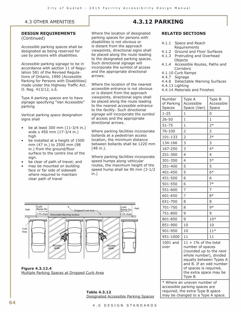
64
C i t y o f G u e l p h - 2 0 1 5 F a c i l i t y A c c e s s i b i l i t y D e s i g n M a n u a l
4 . 0 D E S I G N S T A N D A R D S
4.3 OTHER AMENITIES 4.3.12 PARKING
DESIGN REQUIREMENTS (Continued)
Accessible parking spaces shall be designated as being reserved for use by persons with disabilities.
Accessible parking signage to be in accordance with section 11 of Regu-lation 581 of the Revised Regula-tions of Ontario, 1990 (Accessible Parking for Persons with Disabilities) made under the Highway Traffic Act. O. Reg. 413/12, s.6.
Type A parking spaces are to have signage specifying “Van Accessible” parking
Vertical parking space designation signs shall
• be at least 300 mm (11-3/4 in.) wide x 450 mm (17-3/4 in.) high
• be installed at a height of 1500 mm (47 in.) to 2500 mm (98 in.) from the ground/floor surface to the centre line of the sign.
• be clear of path of travel; and• may be mounted on building
face or far side of sidewalk where required to maintain clear path of travel
Where the location of designated parking spaces for persons with disabilities is not obvious or is distant from the approach viewpoints, directional signs shall be placed along the route leading to the designated parking spaces. Such directional signage will incorporate the symbol of access and the appropriate directional arrows.
Where the location of the nearest accessible entrance is not obvious or is distant from the approach viewpoints, directional signs shall be placed along the route leading to the nearest accessible entrance to the facility. Such directional signage will incorporate the symbol of access and the appropriate directional arrows.
Where parking facilities incorporate bollards at a pedestrian access location, the minimum distance between bollards shall be 1220 mm (48 in.).
Where parking facilities incorporate speed humps along vehicular routes, the maximum height of the speed hump shall be 90 mm (3-1/2 in.)
Access aisle
Access aisle
Curb Ramp Dn.
2-5% slope
Curb Ramp Dn.
2-5% slope
Dropped Curb Area
Detectable Warning Surface
Path Path
CurbStop
Figure 4.3.12.4Multiple Parking Spaces at Dropped Curb Area
Table 4.3.12Designated Accessible Parking Spaces
Number of Parking Spaces
Type A Accessible Space (Van)
Type B Accessible Space
1-25 1 026-50 1 151-75 1 2*76-100 2 2101-133 2 3*134-166 3 3167-250 3 4*251-300 4 4301-350 4 5*351-400 5 5401-450 5 6*451-500 6 6501-550 6 7*551-600 7 7601-650 7 8*651-700 8 8701-750 8 9*751-800 9 9801-850 9 10*851-900 10 10901-950 10 11*951-1000 11 111001 and over
11 + 1% of the total number of spaces (rounded up to the next whole number), divided equally between Types A and B. If an odd number of spaces is required, the extra space may be Type B
* Where an uneven number of accessible parking spaces are required, the extra Type B space may be changed to a Type A space.
RELATED SECTIONS
4.1.1 Space and Reach Requirements
4.1.2 Ground and Floor Surfaces4.1.3 Protruding and Overhead
Objects4.1.4 Accessible Routes, Paths and
Corridors4.1.10 Curb Ramps4.4.7 Signage4.4.8 Detectable Warning Surfaces4.4.13 Lighting4.4.14 Materials and Finishes

C i t y o f G u e l p h - 2 0 1 5 F a c i l i t y A c c e s s i b i l i t y D e s i g n M a n u a l
65 4 . 0 D E S I G N S T A N D A R D S
4.3 OTHER AMENITIES
RATIONALE
Passenger-loading zones are important features for individuals who may have difficulty in walking distances or those who use parallel transit systems. Accessible transit vehicles typically require space for the deployment of lifts or ramps and overhead clearances. Protection from the elements will be beneficial to all users and particularly those that may have difficulty with mobility.
APPLICATION
Where passenger-loading zones are provided, at least one shall comply with this section.
Accessible passenger-loading zones shall be identified with signage complying with applicable provisions of 4.4.7.
If the passenger-loading zone is a designated mobility transit stop zone, it shall comply with all relevant municipal bylaws.
DESIGN REQUIREMENTS
Passenger-loading zones shall
• be on an accessible route complying with 4.1.4;
• provide an access aisle at least 2440 mm (96 in.) wide and 7400 mm (24 ft. 3 in.) long, adjacent and parallel
(24'-3")
(96
) Curb ramp
7400 min
2440
* m
in
Access aisle
Accessible passenger-loading zoneidentification signage
to the vehicle pull-up space. (In a retrofit situation where providing a 2440 mm (96 in.)-wide access aisle is technically infeasible, the access aisle width may be reduced to 2000 mm (78-3/4 in.);
• have a curb ramp complying with 4.1.10 where there are curbs between the access aisle and the vehicle pull-up space; and
• have a minimum vertical clearance of 3600 mm (141-3/4 in.) at the loading zone and along the vehicle access route to such areas to and from the site entrances. Items such as signage or mechanical systems may not reduce this overall clearance.
Figure 4.3.13.2Passenger Loading Zone
* NOTE: In a retrofit situation where it is technically infeasible to provide the required access aisle width, the aisle width may be reduced to 2000 mm (78-3/4 in.)
360
0 m
in(1
41-3
/4)
2440 min(96)
vehicle space
2440 min*(96)
access aisle
Figure 4.3.13.1Clearances atPassenger Loading Zone
RELATED SECTIONS
4.1.1 Space and Reach Requirements
4.1.2 Ground and Floor Surfaces4.1.3 Protruding and Overhead
Objects4.1.4 Accessible Routes, Paths and
Corridors4.1.10 Curb Ramps4.4.7 Signage4.4.8 Detectable Warning Surfaces4.4.13 Lighting4.4.14 Materials and Finishes4.4.15 Texture and Colour
4.3.13 PASSENGER-LOADING ZONES

66
C i t y o f G u e l p h - 2 0 1 5 F a c i l i t y A c c e s s i b i l i t y D e s i g n M a n u a l
4 . 0 D E S I G N S T A N D A R D S
4.3 OTHER AMENITIES 4.3.14 LANDSCAPING MATERIALS AND PLANTINGS
RATIONALE
Landscape materials, trees, shrubs and plants should be selected and located with a wide variety of users in mind. For instance, plants and shrubs with a variety of fragrances can provide an interesting orientation cue for persons with a visual impairment. Using contrasting flowers near walkways can also be helpful as a guide. Plants with thorns may constitute a walking hazard. Plants that drop large seed pods can present slipping hazards, as well as difficulties for pushing a wheelchair. Plantings and tree limbs that overhang pathways can impede all users and be a particular hazard to an individual with a visual impairment.
Raised beds can better allow persons using mobility devices or those that have difficulty in bending over to enjoy or tend to plantings.
The use of unit pavers as a walking/wheeling surface is not recommended, unless they are laid in a location that is not subject to the effects of settlement and frost heave, such as over a structural slab or indoors.
APPLICATION
Landscaping materials and plantings contained within the site shall comply with this section.
Where plant beds are provided for gardening use of the general public, clients, customers or employees, 10% of the area of the plant beds, but not less than one, shall comply with this section. It is preferable to have all plant beds comply with this section.
DESIGN REQUIREMENTS
Accessible plant beds shall be
• raised 460 mm (18 inches) above the adjacent floor or ground surface; and
• located on an accessible route complying with 4.1.4.
The edges of planting beds located immediately adjacent to pedestrian walks, shall incorporate clearly defined, cane-detectable curbs at least 75 mm (3 in.) high.
Where variations in grading immediately adjacent to pedestrian walks are potentially hazardous (particularly to persons who are visually impaired), the hazardous edges of the walk shall incorporate clearly defined, cane-detectable curbs at least 100 mm (4 in.) high.
Shrubs with thorns and sharp edges shall be planted at least 920 mm (36 in.) away from accessible pathways and seating areas.
Plants that drop large seed pods shall not overhang or be positioned near accessible paths or walkways.
Permanent guy wires shall not be used in any area which is intended for use by the general public, clients, customers or employees. Temporary guy wires, such as those used when planting new trees, shall be clearly identified using strong colour contrast.
Tree guards shall conform to 4.1.3.
Overhanging branches of trees or shrubs over walkways or paths shall not reduce the available headroom at any part of the walkway or path to less than 2100 mm (82-3/4 in.).
RELATED SECTIONS
4.1.1 Space and Reach Requirements
4.1.2 Ground and Floor Surfaces4.1.3 Protruding and Overhead
Objects4.1.4 Accessible Routes, Paths and
Corridors4.4.8 Detectable Warning Surfaces4.4.14 Materials and Finishes4.4.15 Texture and Colour

C i t y o f G u e l p h - 2 0 1 5 F a c i l i t y A c c e s s i b i l i t y D e s i g n M a n u a l
67 4 . 0 D E S I G N S T A N D A R D S
4.3.15 BENCHES 4.3 OTHER AMENITIES
RATIONALE
Indoor and outdoor benches provide convenient resting places for all individuals and are especially important for those who may have difficulty with standing or walking for extended periods. Benches should be placed adjacent to pedestrian walkways to provide convenient rest places without becoming potential obstructions. Appropriate seat heights can facilitate sitting and rising for individuals such as senior citizens. Armrests may also provide assistance in sitting and rising. Persons who are blind will find it easier to locate benches if they are located adjacent to a landmark, such as a large tree, a bend in a pathway, or a sound source.
APPLICATION
All benches, except those located in unpaved areas of parks, wilderness, beach or unpaved picnic areas, shall be accessible to persons using wheelchairs or other mobility devices.
DESIGN REQUIREMENTS
Benches shall
• be adjacent to an accessible route complying with 4.1.4;
• be stable;• have a seat height between 450
mm (17-3/4 in.) and 500 mm (19-5/8 in.) from the ground;
• have arm and back rests; • be of contrasting colour to their
background; and• have an adjacent level, firm
ground surface at least 920 mm (36 in.) x 1370 mm (54 in.).
RELATED SECTIONS
4.1.1 Space and Reach Requirements
4.1.2 Ground and Floor Surfaces4.1.3 Protruding and Overhead
Objects4.1.4 Accessible Routes, Paths and
Corridors4.3.2 Viewing Positions4.4.8 Detectable Warning Surfaces4.4.14 Materials and Finishes4.4.15 Texture and Colour
920 min (36)
137
0 m
in
(54)
50 min (2 in.) high curb
Contrasting walking surface
Accessiblepathway
Bench
450
-500
(
17 3
/4-
1
9 5/
8)
Armrests
Figure 4.3.15.1Rest Area
Figure 4.3.15.2Bench Seating
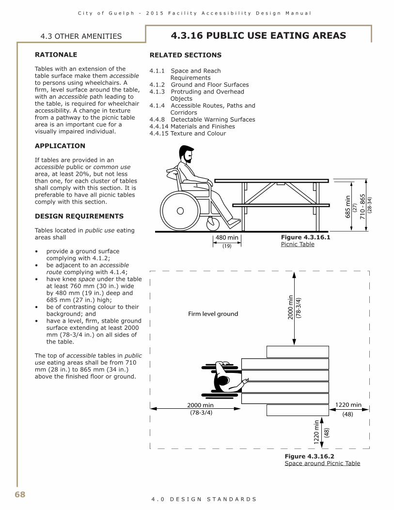
68
C i t y o f G u e l p h - 2 0 1 5 F a c i l i t y A c c e s s i b i l i t y D e s i g n M a n u a l
4 . 0 D E S I G N S T A N D A R D S
4.3.16 PUBLIC USE EATING AREAS4.3 OTHER AMENITIES
RATIONALE
Tables with an extension of the table surface make them accessible to persons using wheelchairs. A firm, level surface around the table, with an accessible path leading to the table, is required for wheelchair accessibility. A change in texture from a pathway to the picnic table area is an important cue for a visually impaired individual.
APPLICATION
If tables are provided in an accessible public or common use area, at least 20%, but not less than one, for each cluster of tables shall comply with this section. It is preferable to have all picnic tables comply with this section.
DESIGN REQUIREMENTS
Tables located in public use eating areas shall
• provide a ground surface complying with 4.1.2;
• be adjacent to an accessible route complying with 4.1.4;
• have knee space under the table at least 760 mm (30 in.) wide by 480 mm (19 in.) deep and 685 mm (27 in.) high;
• be of contrasting colour to their background; and
• have a level, firm, stable ground surface extending at least 2000 mm (78-3/4 in.) on all sides of the table.
The top of accessible tables in public use eating areas shall be from 710 mm (28 in.) to 865 mm (34 in.) above the finished floor or ground.
RELATED SECTIONS
4.1.1 Space and Reach Requirements
4.1.2 Ground and Floor Surfaces4.1.3 Protruding and Overhead
Objects4.1.4 Accessible Routes, Paths and
Corridors4.4.8 Detectable Warning Surfaces4.4.14 Materials and Finishes4.4.15 Texture and Colour
(27)
(2
8-34
)
(19)
480 min
685
min
710
- 86
5
Figure 4.3.16.1Picnic Table
2000 min (78-3/4)
2000
min
(78-
3/4)
1220 min
(48)
Firm level ground12
20 m
in
(
48)
Figure 4.3.16.2Space around Picnic Table

C i t y o f G u e l p h - 2 0 1 5 F a c i l i t y A c c e s s i b i l i t y D e s i g n M a n u a l
69 4 . 0 D E S I G N S T A N D A R D S
RATIONALE
Street furniture can provide a resting place for an individual with difficulty in walking distances. Such furniture should incorporate strong colour contrasts and be located off pathways, to minimize its potential as an obstruction to pedestrians.
APPLICATION
Street furniture, including but not limited to, waste receptacles, light standards, planters, mail boxes, vending machines, tent signs and other signs contained within the site, shall comply with this section, including furniture that is located inside or outside of facilities.
All waste receptacles, except those located in unpaved areas of parks, wilderness, beach or unpaved picnic areas or large industrial containers, shall be accessible to persons using wheelchairs or other mobility devices.
DESIGN REQUIREMENTS
Street furniture shall
• not reduce the required width of an access route as specified in 4.1.4;
• be cane-detectable, in compliance with 4.1.3;
• be located to one side of the normal path of pedestrian travel, as illustrated in 4.3.15.1; and
• be securely mounted on an amenity strip, minimum 600 mm (23-5/8 in.) wide, located adjoining walkways, paths, sidewalks and other accessible routes.
Waste receptacles shall be large enough to contain the anticipated amount of waste, so that overflows do not cause a tripping hazard.
Waste receptacles in accessible open areas, such as parks, wilderness areas, beaches or picnic areas, shall be mounted on firm, level pads.
Waste receptacles shall be clearly identified by suitable lettering, in compliance with the relevant parts of 4.4.7.
Where lids or openings are provided on waste receptacles, they shall be mounted no higher than 1060 mm (42 in.) above the adjacent floor or ground surface. Opening mechanisms shall comply with 4.4.2.
An exterior waste receptacle shall be provided close to each accessible public entrance.
Street furniture shall incorporate pronounced colour contrast to differentiate it from the surrounding environment.
RELATED SECTIONS
4.1.1 Space and Reach Requirements
4.1.2 Ground and Floor Surfaces4.1.3 Protruding and Overhead
Objects4.1.4 Accessible Routes, Paths and
Corridors4.3.15 Benches4.4.8 Detectable Warning Surfaces4.4.14 Materials and Finishes4.4.15 Texture and Colour
4.3.17 STREET FURNITURE 4.3 OTHER AMENITIES

70
C i t y o f G u e l p h - 2 0 1 5 F a c i l i t y A c c e s s i b i l i t y D e s i g n M a n u a l
4 . 0 D E S I G N S T A N D A R D S
4.4 SYSTEMS AND CONTROLS 4.4.1 EMERGENCY EXITS, FIRE EVACUATION AND AREAS OF REFUGE
RATIONALE
In order to be accessible to all individuals, emergency exits must include the same accessibility features as other doors specified in 4.1.6. The doors and routes must also be marked in a way that is accessible to all individuals, including those who may have difficulty with literacy, such as children or persons speaking a different language. Persons with a visual impairment will need a means of quickly locating exits – audio or talking signs could assist. In the event of fire when elevators cannot be used, areas of refuge are an asset to anyone who would have difficulty traversing sets of stairs.
APPLICATION
In facilities, or portions of facilities, required to be accessible, accessible means of egress shall be provided in the same number as required for exits by the Ontario Building Code.
Where required exits from a floor level are not accessible, areas of refuge shall be provided on the floor level in a number equal to that of the required exits.
Every occupiable level in non-residential occupancies above or below the first storey (as defined by the Ontario Building Code) that is accessible, shall
• be served by an elevator that has protection features, as specified in 3.3.1.7 of the Ontario Building Code; or
• be divided into at least two zones by fire separations, as specified in 3.3.1.7 of the Ontario Building Code.
In occupiable levels above or below the first storey in residential occupancies, the requirements for a protected elevator or two fire zones may be waived, if an appropriate balcony (as specified in 3.3.1.7 of the Ontario Building Code) is provided for each suite.
Areas of refuge shall comply with this section.
A horizontal exit meeting the requirements of the Ontario Building Code shall satisfy the requirements for an area of refuge.
DESIGN REQUIREMENTS
Where emergency warning systems are provided, then they shall include both audible alarms and visible alarms. Visual alarms shall comply with 4.4.4.
Accessible means of egress shall comply with 4.1.4.
Accessible means of egress shall be identified with signage complying with applicable provisions of 4.4.7.
Areas of refuge shall
• be located on an accessible route complying with 4.1.4;
• incorporate the number of refuge spaces in accordance with Table 4.4.1;
• be of a size that allows a minimum floor space of 850 mm (33-1/2 in.) x 1370 mm (54 in.) per non-ambulatory occupant;
• be separated from the floor area by a fire separation having a fire-resistance rating at least equal to that required for an exit;
• be served by an exit or firefighters’ elevator;
• be designated as an area of refuge for persons with disabilities on the facility plans and in the facility;
• be smoke protected in facilities of more than three storeys;
• incorporate a 2-way voice com-munication system for use between each area of refuge and the central alarm and con-trol facility; and
• be identified with signage complying with applicable provisions of 4.4.7, stating AREA OF REFUGE and incorporating the international symbol for accessibility for persons with disabilities.
RELATED SECTIONS
4.1.1 Space and Reach Requirements
4.1.2 Ground and Floor Surfaces4.1.3 Protruding and Overhead
Objects4.1.4 Accessible Routes, Paths and
Corridors4.1.6 Doors4.4.2 Controls and Operating
Mechanisms4.4.4 Visual Alarms4.4.7 Signage4.4.8 Detectable Warning Surfaces4.4.9 Public Address Systems4.4.14 Materials and Finishes4.4.15 Texture and Colour
Up
600
Wheelchair space850 x 1370(33-1/2 x 54)
(23-5/8)
Figure 4.4.1.1Area of Refuge
Occupant load of the floor area
served by the area of refuge
Minimum number of refuge spaces
1 to 400 2 Over 400 3 plus 1 for each
additional increment of 200 persons in
excess of 400 persons
Table 4.4.1Number of Refuge Spaces
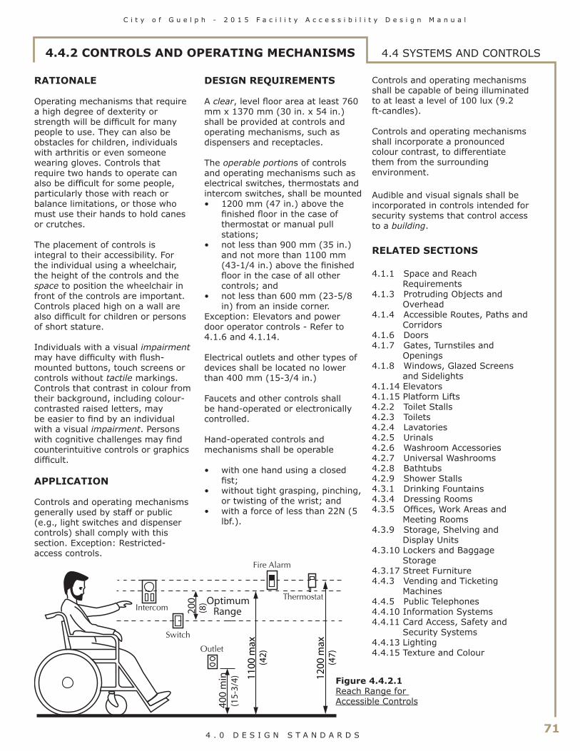
C i t y o f G u e l p h - 2 0 1 5 F a c i l i t y A c c e s s i b i l i t y D e s i g n M a n u a l
71 4 . 0 D E S I G N S T A N D A R D S
4.4.2 CONTROLS AND OPERATING MECHANISMS 4.4 SYSTEMS AND CONTROLS
RATIONALE
Operating mechanisms that require a high degree of dexterity or strength will be difficult for many people to use. They can also be obstacles for children, individuals with arthritis or even someone wearing gloves. Controls that require two hands to operate can also be difficult for some people, particularly those with reach or balance limitations, or those who must use their hands to hold canes or crutches.
The placement of controls is integral to their accessibility. For the individual using a wheelchair, the height of the controls and the space to position the wheelchair in front of the controls are important. Controls placed high on a wall are also difficult for children or persons of short stature.
Individuals with a visual impairment may have difficulty with flush-mounted buttons, touch screens or controls without tactile markings. Controls that contrast in colour from their background, including colour-contrasted raised letters, may be easier to find by an individual with a visual impairment. Persons with cognitive challenges may find counterintuitive controls or graphics difficult.
APPLICATION
Controls and operating mechanisms generally used by staff or public (e.g., light switches and dispenser controls) shall comply with this section. Exception: Restricted-access controls.
DESIGN REQUIREMENTS
A clear, level floor area at least 760 mm x 1370 mm (30 in. x 54 in.) shall be provided at controls and operating mechanisms, such as dispensers and receptacles.
The operable portions of controls and operating mechanisms such as electrical switches, thermostats and intercom switches, shall be mounted• 1200 mm (47 in.) above the
finished floor in the case of thermostat or manual pull stations;
• not less than 900 mm (35 in.) and not more than 1100 mm (43-1/4 in.) above the finished floor in the case of all other controls; and
• not less than 600 mm (23-5/8 in) from an inside corner.
Exception: Elevators and power door operator controls - Refer to 4.1.6 and 4.1.14.
Electrical outlets and other types of devices shall be located no lower than 400 mm (15-3/4 in.)
Faucets and other controls shall be hand-operated or electronically controlled.
Hand-operated controls and mechanisms shall be operable
• with one hand using a closed fist;
• without tight grasping, pinching, or twisting of the wrist; and
• with a force of less than 22N (5 lbf.).
Controls and operating mechanisms shall be capable of being illuminated to at least a level of 100 lux (9.2 ft-candles).
Controls and operating mechanisms shall incorporate a pronounced colour contrast, to differentiate them from the surrounding environment.
Audible and visual signals shall be incorporated in controls intended for security systems that control access to a building.
RELATED SECTIONS
4.1.1 Space and Reach Requirements
4.1.3 Protruding Objects and Overhead
4.1.4 Accessible Routes, Paths and Corridors
4.1.6 Doors4.1.7 Gates, Turnstiles and
Openings4.1.8 Windows, Glazed Screens
and Sidelights4.1.14 Elevators4.1.15 Platform Lifts4.2.2 Toilet Stalls4.2.3 Toilets4.2.4 Lavatories4.2.5 Urinals4.2.6 Washroom Accessories4.2.7 Universal Washrooms4.2.8 Bathtubs4.2.9 Shower Stalls4.3.1 Drinking Fountains4.3.4 Dressing Rooms4.3.5 Offices, Work Areas and
Meeting Rooms4.3.9 Storage, Shelving and
Display Units4.3.10 Lockers and Baggage
Storage4.3.17 Street Furniture4.4.3 Vending and Ticketing
Machines4.4.5 Public Telephones4.4.10 Information Systems4.4.11 Card Access, Safety and
Security Systems4.4.13 Lighting4.4.15 Texture and Colour
1100
max
(42)
400
min
(15-
3/4)
200
(8)Optimum
Range
1200
max
(47)
Figure 4.4.2.1Reach Range for Accessible Controls

72
C i t y o f G u e l p h - 2 0 1 5 F a c i l i t y A c c e s s i b i l i t y D e s i g n M a n u a l
4 . 0 D E S I G N S T A N D A R D S
4.4 SYSTEMS AND CONTROLS 4.4.3 VENDING AND TICKETING MACHINES
RATIONALE
Space in front of vending machines allows for manoeuvrability of mobility aids. Seating areas and tables adjacent to vending machines offer convenience and should accommodate the spatial requirements of wheelchairs. The selection of the machines should include a number of factors. Operating mechanisms should be within reach of children and individuals in wheelchairs. The mechanisms should be operable with one hand and minimal strength, to accommodate a host of disabilities including arthritis, or the need to stabilize oneself with a cane or a handful of bags. Lighting levels and colour contrasts make the machine more accessible to those with a visual impairment.
APPLICATION
Vending and ticketing machines shall comply with this section.
DESIGN REQUIREMENTS
Vending and ticketing machines shall be located on an accessible route in compliance with 4.1.4.
Clear floor space in front of vending and ticketing machines shall conform to 4.1.1.
The controls and operating mechanisms on vending and ticketing machines shall comply with 4.4.2.
Signage on vending and ticketing machines shall be in highly contrasting lettering, at least 13 mm (1/2 in.) high. Ideally, lettering and signage shall comply with relevant parts of 4.4.7.
RELATED SECTIONS
4.1.1 Space and Reach Requirements
4.1.4 Accessible Routes, Paths and Corridors
4.4.2 Controls and Operating Mechanisms
4.4.15 Texture and Colour
Switch
Receptacle
Coin slot
Change return
1200
max
400
min
(47)
(15
3/4)
SNACKS
Figure 4.4.3.1Vending Machine

C i t y o f G u e l p h - 2 0 1 5 F a c i l i t y A c c e s s i b i l i t y D e s i g n M a n u a l
73 4 . 0 D E S I G N S T A N D A R D S
4.4.4 VISUAL ALARMS 4.4 SYSTEMS AND CONTROLS
RATIONALE
Visual alarms are essential safety features for individuals who are deaf, deafened or hard of hearing such that they would not hear an audible alarm.
APPLICATION
Visual alarms shall comply with this section.
At a minimum, visual alarm appliances shall be provided in facilities in each of the following areas: restrooms and any other general usage areas (e.g., meeting rooms), hallways, lobbies and any other areas for common use.
Visual alarm signal appliances shall be integrated into the facility alarm system. If single-station audible alarms are provided, then single-station visual alarms shall be provided.
DESIGN REQUIREMENTS
Visual alarm signals shall have the following minimum photometric and location features:
• the lamp shall be a Xenon strobe type or equivalent;
• the colour shall be clear or nominal white (i.e. unfiltered or clear filtered white light);
• the maximum pulse duration shall be two-tenths of one second (0.2 sec) with a maximum duty cycle of 40 percent. The pulse duration is defined as the time interval between initial and final points of 10% of maximum signal;
• the intensity shall be a minimum of 75 candela;
• the flash rate shall be a minimum of 1 Hz and a maximum of 3 Hz;
• the appliance shall be placed 2100 mm (82-3/4 in.) above the floor level within the space or 150 mm (5-7/8 in.) below the ceiling, whichever is lower;
• in general, no place in any room or space required to have a visual signal appliance, shall be more than 15 meters (50 ft.) from the signal (in the horizontal plane). In large rooms and spaces exceeding 30 meters (100 ft.) across, without obstructions 2000 mm (78-3/4 in.) above the finished floor, such as auditoriums, devices may be placed around the perimeter, spaced a maximum of 30 meters (100 ft.) apart, in lieu of suspending appliances from the ceiling; and
• no place in common corridors or hallways in which visual alarm signalling appliances are required shall be more than 15 meters (50 ft.) from the signal.
RELATED SECTIONS
4.4.1 Emergency Exits, Fire Evacuation and Areas of Refuge

74
C i t y o f G u e l p h - 2 0 1 5 F a c i l i t y A c c e s s i b i l i t y D e s i g n M a n u a l
4 . 0 D E S I G N S T A N D A R D S
4.4 SYSTEMS AND CONTROLS 4.4.5 PUBLIC TELEPHONES
RATIONALE
The placement of telephones should address the limited reach of children or persons seated in wheelchairs. Longer cords facilitate the use of the phone for someone unable to get close to the phone due to a mobility device. Adjustable volume controls are important for hard of hearing individuals, as are shelves that could support a TDD device. A fold-down seat is an asset to some-one having difficulty standing for extended periods. Telephones pro-jecting from a wall may present a hazard, particularly to persons with a visual impairment, if the sides are not configured to be cane-detect-able.
APPLICATION
Where public pay phones, public closed-circuit phones, or other public telephones are provided, they shall comply with this section to the extent required by Table 4.4.5. All telephones required to be accessible shall be equipped with a volume control. In addition, 25%, but never less than one, of all other public telephones provided shall be equipped with a volume control and shall be dispersed among all types of public telephones, including closed-circuit telephones, throughout the facility.
Signage complying with applicable provisions of 4.4.7 shall be provided.
Where an interior public pay telephone is provided, then at least one interior public text telephone (TTY) shall be provided in the facility in a public use area.
Where an interior public pay telephone is provided in the secured area of a detention or correctional facility subject to 4.5.8, then at least one public text telephone shall also be provided in at least one secured area. Secured areas are those areas used only by detainees or inmates and security personnel.
DESIGN REQUIREMENTS
Accessible telephones shall be on an accessible route complying with 4.1.4.
Telephones, enclosures and related equipment shall comply with 4.1.3.
Telephones shall have push-button controls where service for such equipment is available. The characters on the push buttons shall contrast with their background, which should be non-glare (matte finish), and the buttons themselves should contrast with their background.
The minimum handset cord length of accessible telephones shall be 1000 mm (39-3/8 in.).
The minimum illumination level at operating mechanisms, the directory, and shelf of accessible telephones shall be 200 lux (18.4 ft-candles).
Telephones for persons in wheelchairs shall
• have the maximum height of operable portions, including the coin slot, 1200 mm (47 in.) above the floor;
Number of each type of telephone provided on each floor
Number of telephones required to comply with this section
1 or more single unit 1 per floor 1 bank 1 per floor 2 or more banks 1 per bank. Accessible unit may be
installed as a single unit in proximity to (either visible or with signage) the bank. At least one public telephone per floor shall meet the requirements for a forward reach telephone.
Table 4.4.5Accessible Telephone RequirementsNote: A bank consists of two or more adjacent public telephones, often installed as a unit.
740
min
(27
in)
knee
cle
aran
ce
120
0 m
ax (4
7)
to h
igh
est
op
erab
le p
art
775
- 875
(30-
1/2
- 34)
Figure 4.4.5.1Telephone

C i t y o f G u e l p h - 2 0 1 5 F a c i l i t y A c c e s s i b i l i t y D e s i g n M a n u a l
75 4 . 0 D E S I G N S T A N D A R D S
4.4.5 PUBLIC TELEPHONES 4.4 SYSTEMS AND CONTROLS
• have a clear floor space not less than 810 mm (32 in.) wide by 1370 mm (54 in.) deep centred on the telephone;
• have a level telephone directory shelf at least 500 mm (19-3/4 in.) wide and 350 mm (13-3/4 in.) deep and has no obstruction within 250 mm (9-7/8 in.) above the surface;
• have the top surface of the shelf or counter located between 775 - 875 mm (30-1/2 - 34 in.) above the finished floor; and
• have a knee space not less than 740mm (29 in.) high.
Text telephones (TTY’s) used with a pay telephone shall be permanently affixed within, or adjacent to, the telephone enclosure. If an acoustic coupler is used, the telephone cord shall be sufficiently long to allow connection of the text telephone (TTY) and the telephone receiver.
Where additional telephones are provided for use by persons who are deaf or hard of hearing, and these telephones are designed to accommodate a portable text telephone (TTY), the telephones shall
• comply with CSA Standard T515;
1370
810
255m
ax
(54)
(32)
(10)
1370
810
510
max
(54) M
ore
th
an 6
10(2
4)
(32)150min
(6)
(20)
1370
810
510
max
(54)
610
max
(24)
(32)
(20)
• have a shelf at least 250 mm (9-7/8 in.) wide by 350 mm (13-3/4 in.) deep, with at least 250 mm (9-7/8 in.) clear space above the shelf, to accommodate the use of a portable text telephone;
• be equipped with an electrical outlet, within or adjacent to the telephone enclosure; and
• be equipped with a handset capable of being placed flush on the surface of the shelf.
Accessible telephones shall be identified by the appropriate symbol of accessibility for mobility impaired persons and/or persons who are deaf or hard of hearing.
When directional signs for telephones are installed, they shall include the appropriate access
symbols.
RELATED SECTIONS
4.1.1 Space and Reach Requirements
4.1.3 Protruding and Overhead Objects
4.1.4 Accessible Routes, Paths and Corridors
4.4.2 Controls and Operating Mechanisms
4.4.7 Signage4.4.13 Lighting4.4.15 Texture and Colour
Figure 4.4.5.2Parallel Approach
Figure 4.4.5.3Frontal Approach
Figure 4.4.5.4Frontal Approach

76
C i t y o f G u e l p h - 2 0 1 5 F a c i l i t y A c c e s s i b i l i t y D e s i g n M a n u a l
4 . 0 D E S I G N S T A N D A R D S
4.4.6 ASSISTIVE LISTENING SYSTEMS4.4 SYSTEMS AND CONTROLS
RATIONALE
The provision of assistive listening devices is important for the range of individuals who may have difficulty hearing.
Adequate and controllable lighting is required for persons who lip-read, or those who require increased task lighting, due to visual impairment.
APPLICATION
Assistive listening systems shall comply with this section.
This section applies to assembly areas where audible communications are integral to the use of the space (e.g., concert theatres, meeting rooms, classrooms, auditoria, etc.). Such assembly areas, where: (1) they accommodate at least 50 persons or where they have audio amplification systems or where greater than 100 sq.m. (1080 sq.ft.) in floor area; and (2) they have fixed seating, shall have a permanently installed listening system complying with this section. Where it is technically infeasible to provide a permanently installed system (e.g. arena surface) then provisions for a portable assistive listening system may be made.
For other assembly areas, a permanently installed listening system or an adequate number of electrical outlets or other supplementary wiring necessary to support a portable assistive listening system shall be provided. The minimum number of receivers to be provided shall be equal to 4% of the total number of seats, but no less than two.
DESIGN REQUIREMENTS
Signage complying with applicable provisions of 4.4.7 shall be installed to notify patrons of the availability of a listening system.
Induction loops, infrared systems and FM radio frequency systems shall be considered acceptable types of assistive listening systems for persons who are hard of hearing.
Where an induction loop system is installed, dimmer switches and other controls that incorporate transformer coils shall be located so as not to interfere with the audio induction loop.
Where infrared assistive listening devices are used, overhead incandescent lights shall be located so as not to cancel out the infrared signal at the receiver.
Where an FM loop system or other assistive listening devices are available in public facilities or meeting areas, portable headsets that are compatible with personal hearing aids shall be made available.
Where an induction loop system is utilized, at least half the seating area shall be encompassed.
Where the listening system provided serves individual fixed seats, such seats shall be located within a 15-meter (50-ft.) viewing distance of the stage or playing area and shall have a complete view of the stage or playing area.
RELATED SECTIONS
4.4.7 Signage4.4.13 Lighting4.4.16 Acoustics

C i t y o f G u e l p h - 2 0 1 5 F a c i l i t y A c c e s s i b i l i t y D e s i g n M a n u a l
77 4 . 0 D E S I G N S T A N D A R D S
4.4 SYSTEMS AND CONTROLS4.4.7 SIGNAGE
Minimum character height, mm
Maximum viewing distance, mm
200 (7-7/8 in.) 6000 (19 ft. 8 in.) 150 (5-7/8 in.) 4600 (15 ft. 0 in.) 100 (3-15/16 in.) 2500 (8 ft. 2-1/2 in.) 75 (2-15/16 in.) 2300 (7 ft. 6-1/2 in.) 50 (2 in.) 1500 (4 ft. 11 in.) 25 (1 in.) 750 (2 ft. 5-1/2 in.)
Table 4.4.7Character Height on Signs
Figure 4.4.7.1Colour Contrast on Signs
RATIONALE
Signage should be simple, uncluttered and incorporate plain language. The use of graphic symbols is helpful for individuals such as children; those with a limited literacy level; or speak a different language. Sharp contrasts in colour make signage easier for anyone to read, particularly someone with a visual impairment. The intent of the symbol must be evident, culturally universal and not counterintuitive. To enhance readability, raised tactile lettering should incorporate edges that are slightly smoothed.
APPLICATION
Signage shall comply with this section.
Signs that designate permanent rooms or spaces shall be wall-mounted and include tactile characters and numbers.
Signs that provide direction to, or information about, functional spaces, shall comply with this section. Exception: Facility directories, menus and all other signs that are temporary are not required to comply.
Elements and spaces of accessible facilities that shall be identified by the International Symbol of Accessibility are• parking spaces, designated as
reserved for individuals with disabilities;
• accessible passenger loading zones;
• accessible entrances when not all are accessible (inaccessible entrances shall have directional signage to indicate the route to the nearest accessible entrance);
• accessible toilet and bathing facilities, including single-use portable units, when not all are accessible;
• accessible telephones;• accessible elevators and other
elevating devices;• accessible means of egress; and• areas of refuge.
Audible signs (infrared and digital) that are readable by visually impaired persons using a receiving device may be the sole orientation aid across open spaces. Consideration should be given to including wire drops for future installation.
DESIGN REQUIREMENTS
Letters and numbers on signs shall
• be sans serif;*• have Arabic numbers;• have a width-to-height ratio
between 3:5 and 1:1; and
• have a stroke-width-to-height ratio between 1:5 and 1:10.
Character height dimensions for viewing distance shall comply with Table 4.4.7.
Characters, symbols and backgrounds of signs shall have an eggshell, matte or other glare-free finish.
Characters and symbols shall contrast with their background: either light characters on a dark background or dark characters on a light background.
This is a serif font face
* This is a sans serif font face

78
C i t y o f G u e l p h - 2 0 1 5 F a c i l i t y A c c e s s i b i l i t y D e s i g n M a n u a l
4 . 0 D E S I G N S T A N D A R D S
4.4.7 SIGNAGE4.4 SYSTEMS AND CONTROLS
DESIGN REQUIREMENTS(Continued)
Where signs are required to be tactile, letters and numerals shall be
• raised at least 0.8 mm (1/32 in.), not sharply edged;
• be between 16 mm (5/8 in.) and 50 mm (2 in.) high; and
• be sans serif*, accompanied by Grade 2 Braille.
Pictograms shall be accompanied by an equivalent visual and tactile verbal description, placed directly below the pictogram. The border dimension of the pictogram shall be 150 mm (6 in.) minimum in height.
Where a wall mounted tactile sign is provided for rooms and spaces, signs shall be installed on the wall adjacent to the latch side of the door, located with their centre line at a height between 1200 mm (47 in.) and 1500 mm (59 in.) above the finished floor. Where there is no wall space to the latch side of the door, including at double-leaf doors, signs shall be placed on the nearest adjacent wall.
The minimum level of illumination on signs shall be 200 lux (18.4 ft-candles).
1200
-150
0(4
7-59
)
25 m
in
Raised 0.8 min(1/32)
Using Contrasting Colour
Figure 4.4.7.3Tactile Lettering
Figure 4.4.7.4International Symbol of Access
RELATED SECTIONS
4.1.3 Protruding and Overhead Objects
4.1.4 Accessible, Routes, Paths and Corridors
4.1.5 Entrances4.1.6 Doors4.1.7 Gates, Turnstiles and
Openings4.1.9 Ramps4.1.14 Elevators4.1.15 Platform Lifts4.2.1 Toilet and Bathing Facilities4.2.7 Universal Washrooms4.3.2 Viewing Positions4.3.4 Dressing Rooms4.3.12 Parking4.3.13 Passenger-Loading Zones4.4.1 Emergency Exits, Fire
Evacuation and Areas of Refuge
4.4.5 Public Telephones4.4.13 Lighting4.4.15 Texture and Colour
Figure 4.4.7.2Pictograms (Note: Must incorporate equivalent verbal description)

C i t y o f G u e l p h - 2 0 1 5 F a c i l i t y A c c e s s i b i l i t y D e s i g n M a n u a l
79 4 . 0 D E S I G N S T A N D A R D S
4.4 SYSTEMS AND CONTROLS4.4.8 DETECTABLE WARNING SURFACES
RATIONALE
Detectable warning surfaces provide important navigation cues for persons with a visual impairment. These surfaces alert all pedestrians to potential hazards, such as crosswalks or stairs. Suitable surfaces include a change in texture and high colour contrast but should not present a tripping hazard.
Detectable warning surfaces should be used consistently throughout a facility.
APPLICATION
Detectable warnings at walkways, curb ramps, stairs, elevated platforms including transit terminals, escalators, and where used to define potential hazards shall comply with this section.
DESIGN REQUIREMENTS
All textured surfaces used as detectable warning surfaces shall be cane-detectable and clearly differentiated from the surrounding ground or floor surfaces. (Refer also to 4.4.15).
Detectable warning surfaces shall have high tonal contrast with adjacent surfaces, being either light on dark or dark on light.
Detectable warning surfaces at stairs shall extend the full width of the stair for a depth of 610 mm (24 in.) commencing one tread depth back from the stair. (Refer also to 4.1.11)
Detectable warning surfaces at curb ramps, depressed curbs, exit stairs, exterior stairs and elevated platforms shall be composed of flat-topped domes or cones that• are 4-5 mm (0.16 - 0.20 in.)
high;• have top and bottom
dimensions as shown in Table 4.4.8; and
• are arranged in a regular pattern with spacing as shown in Table 4.4.8.
If a walk crosses or joins a vehicular way and the walking surfaces are not separated by curbs, railings or other elements between the pedestrian areas and vehicular areas, the boundary between the areas shall be defined by a continuous detectable warning surfaces. (Refer also to 4.1.10)
Detectable warning surfaces shall also be provided in areas where a change in elevation occurs in an unexpected location. (Refer also to 4.3.3)
RELATED SECTIONS
4.1.3 Protruding and Overhead Objects
4.1.4 Accessible Routes, Paths and Corridors
4.1.9 Ramps4.1.10 Curb Ramps4.1.11 Stairs4.1.12 Escalators4.3.1 Drinking Fountains4.3.3 Elevated Platforms4.3.12 Parking4.3.13 Passenger-Loading Zones4.4.15 Texture and Colour
1475-1525(58-60)
610 min
(24)
Tread
Visual contrast ontop and frontface of nosing
depth
Figure 4.4.8.1Detectable Warnings at Stairs
Variessee table
4.4.8
Plan
Elevation (enlarged)
4-5(3/16 to 7/32)
Variessee table
4.4.8
Vari
esse
e ta
ble
4.4.
8
Figure 4.4.8.2Flat-topped domes or cones Detectable Warning Surface
Top diameter of flat-topped
domes or cones Spacing
12 (0.5) 42 - 61 (1.7 - 2.4)15 (0.6) 45 - 63 (1.8 - 2.5)18 (0.7) 48 - 65 (1.9 - 2.6)20 (0.8) 50 - 68 (2.0 - 2.7)25 (1.0) 55 - 70 (2.2 - 2.8)
Bottom diameter of flat-topped domes or cones 10 +- greater than the top diameter.
Table 4.4.8Size and spacing of flat-topped domes or cones

80
C i t y o f G u e l p h - 2 0 1 5 F a c i l i t y A c c e s s i b i l i t y D e s i g n M a n u a l
4 . 0 D E S I G N S T A N D A R D S
4.4.9 PUBLIC ADDRESS SYSTEMS4.4 SYSTEMS AND CONTROLS
RATIONALE
Public address systems should be designed to best accommodate all users, especially those that may be hard of hearing. They should be easy to hear above the ambient background noise of the environment and there should be no distortion or feedback. Background noise should be minimized.
Visual equivalents should be made available for individuals who may not hear an audible public address system.
APPLICATION
Public address systems shall comply with this section.
DESIGN REQUIREMENTS
Public address speakers shall be mounted above head level, and provide effective sound coverage in required areas, such as corridors, assembly and meeting room areas, recreational and entertainment facilities, educational facilities, and common use areas in institutional settings.
Public address systems shall be zoned so that information can be directed to key locations only, minimizing background noise in other areas.
Where public address systems are used to broadcast background music, the music shall not be broadcast continuously or throughout the entire facility.
All-point call systems shall only be utilized for fire and emergency information.
Paging systems for staff and other key persons shall be discreet and low volume, and sound only at those devices or locations where such persons might expect to be located.
RELATED SECTIONS
4.4.1 Emergency Exits, Fire Evacuation and Areas of Refuge
4.4.16 Acoustics

C i t y o f G u e l p h - 2 0 1 5 F a c i l i t y A c c e s s i b i l i t y D e s i g n M a n u a l
81 4 . 0 D E S I G N S T A N D A R D S
4.4 SYSTEMS AND CONTROLS
RATIONALE
Information should be accessible to all facility users. Where universally accessible formats are not possible then alternate formats should be available. Video display terminals may present particular difficulties for persons with visual impairments. Alternate technology or audio interfaces are required. To ensure that a person using a wheelchair can access an information terminal, consideration should be given to the lower vantage point and reach ranges.
APPLICATION
Information systems, such as display kiosks and video display terminals, shall comply with this section.
DESIGN REQUIREMENTS
Where information is provided by video display terminals to the general public, clients or customers, the same information shall be provided in an alternative format, such as audio, Braille and large-text print. The minimum font size for large text print shall be 16 point.
Information systems designed for direct access by the public, such as touch-screen video display, keyboard or keypad access, shall be mounted at a height suitable for use by persons using wheelchairs or scooters (Refer to 4.4.2).
Where information is provided by a self-serve kiosk, the kiosk must comply with the Accessibility for Ontarians with Disabilities Act, Integrated Accessibility Standard Regulation 6 Self-Serve Kiosks.
Essential print information shall be printed in large text on a highly contrasting background colour, and should also be available in other formats, such as audiotape and large-text print.
Push buttons or other controls for accessing public information systems should be clearly identifiable by colour and/or tone from the background colour, and should include raised numbers, numerals or symbols for easy identification by persons who are visually impaired. Tactile identification shall comply with 4.4.15.
RELATED SECTIONS
4.4.2 Controls and Operating Mechanisms
4.4.15 Texture and Colour
4.4.10 INFORMATION SYSTEMS

82
C i t y o f G u e l p h - 2 0 1 5 F a c i l i t y A c c e s s i b i l i t y D e s i g n M a n u a l
4 . 0 D E S I G N S T A N D A R D S
4.4 SYSTEMS AND CONTROLS 4.4.11 CARD ACCESS, SAFETY ANDSECURITY SYSTEMS
RATIONALE
In many cases, persons such as seniors and persons with disabilities may be considered to have a higher degree of vulnerability and therefore seek more reassurance and inherent security. Items such as adequate lighting and accessible signalling devices promote this security. Emergency signalling devices are important in universal washrooms where the potential for a fall is increased and an individual may be alone.
Where card-access systems are selected as a means of entry to particular facilities or spaces, the systems and components selected should be suitable for use by persons with varying abilities, including persons with reduced manual dexterity, poor vision or difficulty with reaching. The use of heat-sensing activation buttons should be avoided, as they are indiscernible to a person who is blind.
APPLICATION
Card-access, safety and security systems shall comply with this section.
DESIGN REQUIREMENTS
Adequate lighting shall be provided continuously along public walkways, steps and ramps that are actively used at all times of year and/or where staff and public parking is provided.
Where public telephones are installed, an accessible public telephone complying with 4.4.5 shall be located at, or close to an accessible entrance, for the use of persons requiring assistance.
Where universal washrooms in compliance with 4.2.7 are provided in larger public facilities, such as recreation facilities, the washroom shall incorporate an emergency call system linked to a central location (e.g., office or switchboard).
Card-entry systems shall
• be wall-mounted, no higher than 1060 mm (42 in.) above the floor or ground, adjacent to the door, free of the door swing and min 600 mm (23-5/8 in) from an inside corner;
• be colour-contrasted from the surface on which they are mounted;
• incorporate a card slot that is illuminated or colour contrasted from the mounting plate; and
• use cards that incorporate a distinctive colour, texture or raised graphic/lettering on one side.
Encoded-entry/exit systems, such as keypads, shall
• be wall-mounted, no higher than 1060 mm (42 in.) above the floor or ground, adjacent to the door, free of the door swing and min 600 mm (23-5/8 in) from an inside corner;
• incorporate buttons that • are raised;• are mounted on a clearly
differentiated coloured background; and
• include raised numerals or letters in a constant array.
Audible and visual signals shall be incorporated in controls intended for security systems that control access to a building.
RELATED SECTIONS
4.1.1 Space and Reach Requirements
4.1.4 Accessible Routes Paths and Corridors
4.1.5 Entrances4.1.6 Doors4.1.14 Elevators4.1.15 Platform Lifts4.2.7 Universal Washrooms4.3.5 Offices, Work Areas and
Meeting Rooms4.4.2 Controls and Operating
Mechanisms4.4.13 Lighting4.4.15 Texture and Colour

C i t y o f G u e l p h - 2 0 1 5 F a c i l i t y A c c e s s i b i l i t y D e s i g n M a n u a l
83 4 . 0 D E S I G N S T A N D A R D S
4.4 SYSTEMS AND CONTROLS4.4.12 GLARE AND LIGHT SOURCES
RATIONALE
Direct or reflected glare off of floors, walls or work surfaces is uncomfortable for all users and a barrier to persons with reduced vision. Therefore, every attempt should be made to select light sources, materials and finishes which do not add to the problem, and to ensure that natural daylight is controllable.
The strategic use of lighting is valuable to all individuals, and especially important for individuals with some form of visual impairment. In addition, offering a variety of task lighting at work areas is beneficial to all.
APPLICATION
Systems used to control glare and excessive reflected light shall comply with this section.
DESIGN REQUIREMENTS
Monolithic floor surfaces, such as stone, granite, marble or terrazzo, shall have a matte or honed finish, to minimize reflected glare. Finishes such as vinyl, other composition materials, quarry tile, glazed tile or mosaics, used on horizontal surfaces, such as floors and work surfaces, shall be in satin finishes.
Finishes such as paint, vinyl wall coverings, stone, marble, wood, metals, plastic laminate, etc., used on vertical surfaces, such as walls and columns, shall have matte or satin finishes.
Extensive high-gloss floor or wall finishes are not acceptable, but high-gloss materials may be incorporated into finish details,as long as they do not result in large reflective surfaces.
Curtains, blinds or other sun-screening systems shall be provided at windows and other places where direct sunlight can adversely affect the level of lighting and/or reflected glare.
Light fixtures shall be selected with diffusers, lenses or recessed light sources, so that no glare is created.
Where surface-mounted fluorescent ceiling fixtures are mounted below 2440 mm (96 in.), they shall have darkened sides (i.e., not wrap-around lenses) and be positioned perpendicular to the dominant direction of travel, or used in valance-type lighting at the sides of the space, so that the lighting is indirect.
The location of special features and key orientation elements shall be enhanced through the use of supplementary lighting. Such lighting shall have upward or downward components only.
RELATED SECTIONS
4.1.2 Ground and Floor Surfaces4.1.4 Accessible Routes, Paths and
Corridors4.1.5 Entrances4.1.8 Windows, Glazed Screens
and Sidelights4.1.9 Ramps4.1.10 Curb Ramps4.1.11 Stairs4.1.13 Escalators4.1.14 Elevators4.1.15 Platform Lifts4.2.1 Toilet and Bathing Facilities4.3.8 Information, Reception and
Service Counters4.4.13 Lighting

84
C i t y o f G u e l p h - 2 0 1 5 F a c i l i t y A c c e s s i b i l i t y D e s i g n M a n u a l
4 . 0 D E S I G N S T A N D A R D S
4.4.13 LIGHTING4.4 SYSTEMS AND CONTROLS
RATIONALE
Artificial lighting and natural light sources should provide comfortable, evenly distributed light at all working areas, in all circulation routes and in all areas of potential hazard. Also, outdoor lighting should be provided at entrances, along frequently used access routes and at frequently used outdoor amenities.
APPLICATION
Exterior and interior lighting systems shall comply with this section.
DESIGN REQUIREMENTS
EXTERIOR LIGHTING
Exterior lighting shall be in compliance with Illuminating Engineering Society of North America Standards in all public thoroughfares, and at all pedestrian routes, to provide safe access for persons with disabilities from sidewalks, bus stops and parking areas to nearby facilities and amenities.
At pedestrian entrances, lighting levels should be minimum 100 lux (9.4 ft-candles) consistently over the entrance area, measured at the ground.
Over frequently used pedestrian routes, including walkways, paths, stairs and ramps, lighting levels shall be minimum 30 lux (3 ft-candles) consistently over the route, measured at the ground.
At frequently used accessible parking spaces and limited mobility spaces, lighting levels shall be minimum 30 lux (3 ft-candles) consistently over the parking spaces, measured at the ground.
Lighting levels at passenger drop-off areas shall be minimum 30 lux (3 ft-candles) consistently over the drop-off area, measured at the ground.
At frequently used steps and stairs, lighting shall be located at or beside the steps or stairs, to clearly define the treads, risers and nosings.
All lighting shall
• provide a good colour spectrum; and
• be evenly distributed to minimize cast shadows.
Supplementary lighting shall be provided to highlight key signage and orientation landmarks.
Low-level lighting shall be high enough to clear normal snow accumulation.
Lighting fixtures shall comply with the relevant parts of 4.1.3 and 4.3.17.
INTERIOR LIGHTING
Light sources and fixtures shall be selected to minimize direct glare or indirect glare on nearby reflective surfaces.
Light sources shall provide as full a spectrum of light as possible, as an aid to edge and colour definition.
Lighting shall be configured to create an even distribution at floor level and to minimize pools of light and areas of shadow.
The leading edge of stairs, steps, ramps or escalators shall be evenly lighted to minimize tripping hazards.
Lighting levels in elevator lobbies shall be similar to the lighting levels in elevator cabs, to minimize tripping hazards, and in no case shall be less than 200 lux (20 ft-candles).
Lighting levels in washrooms and dressing rooms shall be evenly distributed and no less than 200 lux (20 ft-candles).
Lighting levels in office areas shall be evenly distributed and no less than 300 lux (30 ft-candles).
Emergency lighting over stairs and ramps, in an exit or path of travel, shall be at least 100 lux (10 ft-candles), generally at the walking surface, and in no place less than 50 lux (5 ft-candles).
Lighting over directional or informational signage, or highlighting other orientation features, at public telephones, information or service counters, and card or keypad security systems, shall be no less than 200 lux (20 ft-candles) at the working surface.
Lighting in meeting rooms and assembly areas shall be evenly distributed, and shall be capable of being adjusted (e.g., dimmers).
Lighting at lecterns, podiums/platforms or other speaker locations shall be capable of being enhanced, even when other lighting is dimmed, to permit ease of lip-reading and/or viewing of the hand actions of a nearby signer for persons who are deaf.
RELATED SECTIONS
4.1.4 Accessible Routes, Paths and Corridors
4.1.5 Entrances4.1.9 Ramps4.1.10 Curb Ramps4.1.11 Stairs4.1.12 Escalators4.1.14 Elevators4.1.15 Platform Lifts4.2.1 Toilet and Bathing Facilities4.3.1 Drinking Fountains4.3.3 Elevated Platforms4.3.4 Dressing Rooms4.3.5 Office, Work Areas and
Meeting Rooms4.3.8 Information, Reception and
Service Counters4.4.2 Controls and Operating
Mechanisms4.4.5 Public Telephones4.4.7 Signage4.4.12 Glare and Light Sources

C i t y o f G u e l p h - 2 0 1 5 F a c i l i t y A c c e s s i b i l i t y D e s i g n M a n u a l
85 4 . 0 D E S I G N S T A N D A R D S
4.4 SYSTEMS AND CONTROLS4.4.14 MATERIALS AND FINISHES
RATIONALE
The selection of flooring materials can be critical to the safe and easy movement of persons using all kinds of mobility aids, as well as persons with low vision.
Floor finishes, such as carpet, should be selected and installed so that persons using wheelchairs and walkers or other mobility aids can easily travel over them without using undue energy or tripping. Finishes that are slip resistant and not highly reflective also promote safe travel.
APPLICATION
Exterior and interior materials and finishes shall comply with this section.
DESIGN REQUIREMENTS
EXTERIOR FINISH MATERIALS
Suitable paving surfaces for walkways include macadam, concrete, or compacted gravel screenings. Texture of materials shall be limited to that required for slip resistance. Such materials used as walkways shall
• have joints that are no greater than 6 mm (1/4 in.) wide, with variations in level of no more than 3 mm (1/8 in); and
• be laid to drain.
Where possible, gratings and grills shall be located to one side of the pedestrian walkways, so as not to impede the accessible route. Where this is not possible, the bars of the grating or grill shall be located perpendicular to the dominant path of travel, with openings of no greater than 13 mm (1/2 in.).
Steps shall be finished with a non-slip material and incorporate highly contrasted nosings.
Ramp surfaces shall be firm and non-slip.
Handrails and guards shall be continuous, smooth and well maintained.
INTERIOR MATERIALS AND FINISHES
Carpet shall be of low-level loop construction, 10- or 12-gauge non-static fibre, directly glued to the subfloor.
Where hard, monolithic materials are selected, they shall be non-slip and non-glare, complying with 4.4.12.
Where floor tiles, bricks or pavers are used, joints should be no wider than 6 mm (1/4 in.) and should be flush.
Wall surfaces in corridors shall be non-abraisive below 2000 mm (78-3/4 in.)
RELATED SECTIONS
4.1.2 Ground and Floor Surfaces4.1.4 Accessible Routes, Paths and
Corridors4.1.5 Entrances4.1.9 Ramps4.1.10 Curb Ramps4.1.11 Stairs4.1.13 Escalators4.1.14 Elevators4.1.15 Platform Lifts4.2.1 Toilet and Bathing Facilities4.3.4 Dressing Rooms4.3.5 Office, Work Areas and
Meeting Rooms4.4.12 Glare and Light Sources
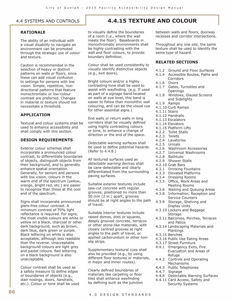
86
C i t y o f G u e l p h - 2 0 1 5 F a c i l i t y A c c e s s i b i l i t y D e s i g n M a n u a l
4 . 0 D E S I G N S T A N D A R D S
4.4 SYSTEMS AND CONTROLS 4.4.15 TEXTURE AND COLOUR
RATIONALE
The ability of an individual with a visual disability to navigate an environment can be promoted through the strategic use of colour and texture. Caution is recommended in the selection of heavy or distinct patterns on walls or floors, since these can add visual confusion to settings for persons with low vision. Simple, repetitive, non-directional patterns that feature monochromatic or low-colour contrast are preferred. Changes in material or texture should not necessitate a threshold.
APPLICATION
Textural and colour systems shall be used to enhance accessibility and shall comply with this section.
DESIGN REQUIREMENTS
Exterior colour schemes shall incorporate a pronounced colour contrast, to differentiate boundaries of objects, distinguish objects from their background, and to generally enhance spatial orientation. Generally, for seniors and persons with low vision, colours in the warm end of the spectrum (yellow, orange, bright red, etc.) are easier to recognize than those at the cool end of the spectrum.
Signs shall incorporate pronounced glare-free colour contrast. A minimum contrast of 70% light reflectance is required. For signs, the most visible colours are white or yellow on a black, charcoal or other dark background, such as brown, dark blue, dark green or purple. Black lettering on white is also acceptable, although less readable than the reverse. Unacceptable background colours are light grey and pastel colours. Red lettering on a black background is also unacceptable.
Colour contrast shall be used as a safety measure to define edges or boundaries of objects (e.g., stair nosings, doors, handrails, etc.). Colour or tone shall be used
to visually define the boundaries of a room (i.e., where the wall meets the floor). Baseboards in monochromatic environments shall be highly contrasting with the wall and floor colours, to provide boundary definition.
Colour shall be used consistently to visually identify distinctive objects (e.g., exit doors).
Bright colours and/or a highly contrasting tone shall be used to assist with wayfinding. (e.g. If used as part of a signage band located on walls at eye level, this band is easier to follow than monolithic wall colouring, and can be the visual cue for other essential signs.)
End walls or return walls in long corridors shall be visually defined using highly contrasting colours or tone, to enhance a change of direction or the end of the space.
Detectable warning surfaces shall be used to define potential hazards. (Refer to 4.4.8.)
All textured surfaces used as detectable warning devices shall be cane-detectable and clearly differentiated from the surrounding paving surfaces.
Suitable exterior textures include saw-cut concrete with regular grooves, positioned no more than 50 mm (2 in.) apart; grooves should be at right angles to the path of travel.
Suitable interior textures include raised domes, dots or squares, deeply grooved concrete, terrazzo or other stone-like materials, with closely centred grooves at right angles to the path of travel, or applied carborundum or other non-slip strips.
Supplementary textural cues shall also be provided (e.g., by using different floor textures or materials, in major and minor routes).
Clearly defined boundaries of materials like carpeting or floor tiles shall enhance wayfinding by defining such as the junction
between walls and floors, doorway recesses and corridor intersections.
Throughout any one site, the same texture shall be used to identify the same type of hazard.
RELATED SECTIONS
4.1.2 Ground and Floor Surfaces4.1.4 Accessible Routes, Paths and
Corridors4.1.6 Doors4.1.7 Gates, Turnstiles and
Openings4.1.8 Windows, Glazed Screens
and Sidelights4.1.9 Ramps4.1.10 Curb Ramps4.1.11 Stairs4.1.12 Handrails4.1.13 Escalators4.1.14 Elevators4.1.15 Platform Lifts4.2.2 Toilet Stalls4.2.3 Toilets4.2.4 Lavatories4.2.5 Urinals4.2.6 Washroom Accessories4.2.7 Universal Washrooms4.2.8 Bathtubs4.2.9 Shower Stalls4.2.10 Grab Bars4.3.1 Drinking Fountains4.3.3 Elevated Platforms4.3.4 Dressing Rooms4.3.5 Office, Work Areas and
Meeting Rooms4.3.6 Waiting and Queuing Areas4.3.8 Information, Reception and
Service Counters4.3.9 Storage, Shelving and
Display Units4.3.10 Lockers and Baggage
Storage4.3.11 Balconies, Porches, Terraces
and Patios4.3.14 Landscaping Materials and
Plantings4.3.15 Benches4.3.16 Public Use Eating Areas4.3.17 Street Furniture4.4.1 Emergency Exits, Fire
Evacuation and Areas of Refuge
4.4.2 Controls and Operating Mechanisms
4.4.5 Public Telephones4.4.7 Signage4.4.8 Detectable Warning Surfaces4.4.11 Card Access, Safety and
Security Systems

C i t y o f G u e l p h - 2 0 1 5 F a c i l i t y A c c e s s i b i l i t y D e s i g n M a n u a l
87 4 . 0 D E S I G N S T A N D A R D S
RATIONALE
The acoustic environment of public buildings and spaces should accommodate the unique needs of persons who are hard of hearing and who need to differentiate essential sounds from general background noise. The sound transmissions of different areas can be used as an orientation cue and help to navigate a space. A well designed acoustical environment is to everyone's advantage.
APPLICATION
The acoustical environment of facilities used by the general public, clients, customers and employees shall comply with this section.
DESIGN REQUIREMENTS
Floor finishes, wall surfaces and ceilings shall be selected so that occasional noise is not unduly amplified. (e.g., Hard surfaces such as marble or terrazzo will allow each foot step to be heard by persons who are visually impaired, but add another level of confusion for persons who are hearing impaired.)
At accessible routes in large facilities where wayfinding is problematic, the sound transmission/reflection characteristics of finish materials shall aurally differentiate major and secondary paths of travel.
Ceiling shapes shall be designed so that echoes do not occur, unless an alternate acoustical treatment is incorprated. (Note: domed shapes tend to distort sound.)
Public address and call systems shall be capable of being zoned to key areas, rather than blanketing all areas of a facility at all times. (Refer to 4.4.9.)
In meeting rooms and assembly areas where the spoken word is key to comprehending the proceedings, all unnecessary background noise (e.g., from fans or other mechanical equipment, air diffusers, etc.) shall be dampened and/or the room shall include adequate sound insulation.
RELATED SECTIONS
4.3.5 Office, Work Areas and Meeting Rooms
4.3.8 Information, Reception and Service Counters
4.4.5 Public Telephones4.4.6 Assitive Listening Systems4.4.9 Public Address Systems
4.4.16 ACOUSTICS 4.4 SYSTEMS AND CONTROLS

88
C i t y o f G u e l p h - 2 0 1 5 F a c i l i t y A c c e s s i b i l i t y D e s i g n M a n u a l
4 . 0 D E S I G N S T A N D A R D S
RATIONALE
Pedestrian crossovers should be designed to accommodate all users equally. The physical location of the controls can help identify specific directional paths, and auditory signals will enable user with low vision to locate the controls quickly.
APPLICATION
Where new pedestrian signals are being installed or existing pedestrian signals are being replaced at a pedestrian crossover, they must be accessible pedestrian signals.
DESIGN REQUIREMENTS
Accessible pedestrian signals must;
• have a locator tone that is distinct from a walk indicator tone
• be installed within 1500 mm (59 in.) of the edge of the curb
• be mounted at a maximum of 1100 mm (43-1/4 in.) above ground level
• have tactile arrows that align with the direction of crossing
• include both manual and automatic activation features
• include both audible and vibro-tactile walk indicators
Where two accessible pedestrian signal assemblies are installed on the same corner, they must be a minimum of 3000mm (118 in.) apart.
Where the accessible pedestrian signal cannot meet the 3000 mm (118 in.) minimum requirement due to site constraints or existing infrastructure, two accessible pedestrian signal assemblies can be installed on a single post, and when this occurs, a verbal announcement must clearly state which crossing is active
In this section, "pedestrian crossover' means a pedestrian crossover as defined in subsection 1 (1) of the Highway Traffic Act
RELATED SECTIONS
4.1.4 Accessible Routes, Paths, And Corridors4.4.2 Controls and Operating Mech-anisms
4.4 SYSTEMS AND CONTROLS 4.4.17 PEDESTRIAN SIGNALS

C i t y o f G u e l p h - 2 0 1 5 F a c i l i t y A c c e s s i b i l i t y D e s i g n M a n u a l
89 4 . 0 D E S I G N S T A N D A R D S
4.5 FACILITY-SPECIFIC REQUIREMENTS4.5.1 ARENAS, HALLS AND OTHER
INDOOR RECREATIONAL FACILITIESRATIONALE
Opportunities for recreation, leisure and active sport participation should be available to all members of the community. Access should be provided to halls, arenas, and other sports facilities, including access to the site, all activity spaces, gymnasia, fitness facilities, lockers, change rooms and showers. Persons with a disability may be active participants, as well as spectators, volunteers and members of staff.
APPLICATION
In addition to the design requirements specified in 4.1 to 4.4, arenas, halls and other indoor recreation facilities shall comply with this section.
Where dressing facilities are provided for use by the general public, clients, customers, performers or staff, at least 50%, but never less than one, for each type of use in each cluster of dressing facilities shall be accessible and in compliance with 4.3.4. It is preferable to have all dressing facilities accessible.
DESIGN REQUIREMENTS
Arenas, halls and other indoor recreation facilities shall
• where visitor, spectator and/or participant seating is provided, have accessible seating options in compliance with 4.3.2;
• provide an accessible route in compliance with 4.1.4 to the arena/facility floor and/or ice surface, including access panels or gates providing at least 950 mm (37-1/2 in.) clear width;
• where facilities are provided for performances and other events, have a direct accessible route in compliance with 4.1.4 from the lobby/entrances and viewing locations to all performing areas, including stages, dressing rooms, washrooms and all other spaces used by performers.
• where dressing facilities are provided, have dressing facilities that comply with 4.3.4;
• where lockers or shelving is provided, have lockers and shelving that comply with 4.3.9 and 4.3.10;
• where coat hooks are provided, have at least 10%, but never less than one, within the reach ranges specified in 4.1.1;
• where toilets and bathing facilities are provided, have toilets and bathing facilities that comply with 4.2.1;
• where concessions or other service counters are provided, comply with 4.3.8;
• where swimming pool, hot pools or therapy pools are provided, comply with 4.5.3; and
• where staff accommodation and related support areas, offices or meeting rooms are provided, comply with all relevant sections of 4.1 to 4.4.
RELATED SECTIONS
All relevant parts of Sections 4.1, 4.2, 4.3 and 4.4.

90
C i t y o f G u e l p h - 2 0 1 5 F a c i l i t y A c c e s s i b i l i t y D e s i g n M a n u a l
4 . 0 D E S I G N S T A N D A R D S
4.5.2 OUTDOOR RECREATIONAL FACILITIES4.5 FACILITY-SPECIFIC
REQUIREMENTS
RATIONALE
Opportunities for recreation, leisure and active sport participation should be available to all members of the community. Access should be provided to playing fields and other sports facilities, including access to the site, all activity areas, outdoor trails, docks, swimming areas, play spaces, lockers, change rooms and showers. Persons with a disability may be active participants, as well as spectators, volunteers and members of staff.
APPLICATION
In addition to the design requirements specified in 4.1 to 4.4, the outdoor recreation facilities listed below shall comply with this section.
Where dressing facilities are provided for use by the general public, clients, customers, performers or staff, at least 50%, but never less than one, for each type of use in each cluster of dressing facilities shall be accessible and in compliance with 4.3.4. It is preferable to have all dressing facilities accessible.
DESIGN REQUIREMENTS
GENERAL
Parks accessibility shall encompass the development of routes, auxiliary services, planting and an overall environment which is accessible and provides a fulfilling recreational experience.
BOARDWALKS
Where boardwalks are provided, they shall
• have a minimum width of 2000 mm (78-3/4 in.);
• have a clear height that pro-vides a minimum head room clearance of 2100 mm (82-3/4 in.) above the boardwalk;
• incorporate surfaces constructed of firm, stable, non-slip materials. (Where wooden planks are used, they shall be laid perpendicular to the path
of travel and have joints no greater than 6 mm (1/4 in.));
• have no openings in the surface that allow the passage of an object that has a diameter of more than 13 mm (1/2 in.);
• incorporate a continuous up-stand edge where the grade drop-off on any side of the boardwalk is greater than 200 mm (7-7/8 in.). The up-stand edge shall be at least 75 mm (3 in.) high and of a contrasting colour to the surrounding terrain;
• have handrails, guards or other suitable barriers on both sides where the grade drop-off is greater than 450 mm (17-3/4 in.);
• have access points that allow easy wheelchair access; and
• benches, garbage cans, drinking fountains, etc., where provided, shall be located adjacent to the boardwalk on firm, level surfaces at the same elevation as the boardwalk. (Refer also to 4.3.17.)
DOCKS
Where docks for fishing, boating or swimming are provided they shall
• be located on an accessible route in compliance with 4.1.4;
• where changes in elevation are necessary, incorporate ramps or curb ramps in compliance with 4.1.8 and 4.1.9. Ramps with a slope no greater than 1:12 are acceptable;
• incorporate a continuous up-stand edge, at least 75 mm (3 in.) high and of a contrasting colour where dock surfaces are greater than 200 mm (7-7/8 in.) above the surface of the water;
• incorporate a guard where dock surfaces are greater than 450 mm (17-3/4 in.) above the surface of the water; and
• where steps are provided to access the water for swimming, incorporate colour-contrasting handrails at the steps. Such handrails shall extend to a minimum of 600 mm (23-5/8 in.) above the dock surface and return down to the dock.
OUTDOOR POOLS
Outdoor swimming pools shall comply with 4.5.3.
TRAILS AND FOOTBRIDGES
This section is applicable to newly constructed and redeveloped recreational trails that an obligated organization intends to maintain, but does not apply to the following types of recreational trails:
1. Trails solely intended for cross-country skiing, mountain biking or the use of motorized snow vehicles or off-road vehicles.
2. Wilderness trails, backcountry trails and portage routes.
Consultation Requirements:Obligated organizations shall consult on the following before they construct new or redevelop existing recreational trails:
1. The slope of the trail2. The need for, and location of,
ramps on the trail3. The need for, location and design
of;i. rest areas,ii. passing areas,iii. viewing areas,iv. amenities on the trail, andv. any other pertinent feature
Obligated organizations shall consult on the matters referred to above in the following manner:
1. Obligated organizations must consult with the public and persons with disabilities
2. Municipalities must also consult with their municipal accessibility advisory committees, where one has been extablished in accordance with the subsection 29 (1) or (2) of the Accessibility for Ontarians with Disabilities Act.
The entrance to a recreational trail must provide a clear opening of between 850 mm and 1,000 mm, whether the entrance includes a gate, bollard or other entrance design.

C i t y o f G u e l p h - 2 0 1 5 F a c i l i t y A c c e s s i b i l i t y D e s i g n M a n u a l
91 4 . 0 D E S I G N S T A N D A R D S
4.5.2 OUTDOOR RECREATIONAL FACILITIES4.5 FACILITY-SPECIFIC
REQUIREMENTS
Where significant changes in grade occur, trail routes shall ideally be sloped at no greater than 1:20. Where technically infeasible to provide a 1:20 slope, intermediate slopes of 1:12 to 1:20 shall have level rest areas min 9m apart and at changes of direction. Slopes of 1:12 shall have adjacent steps and ramps.
Where steps, footbridges or ramps are used, the surfacing shall be of non-slip materials and include suitable colour-contrasting handrails and/or guards.
The slope on bridges shall not exceed 1:20.
Where adjacent to water or a drop off, edge protection is to be provided, consisting of an elevated barrier that runs along the edge of the recreational trail with a minimum height of 50mm (2in.) above the trail surface. Where edge protection is provided, it should not impede the drainage of the trail surface.
Where a protective barrier is provided, edge protection is not required.
Trails shall feature a tactile map at the start of the trail and periodically along its length. Information to be provided includes;
• length of trail; • type of surface of which the trail
is constructed; • average and MIN width;• average and MAX running slope
and cross slope, and• locations of amenities where
provided.
Signage text to comply with section 4.4.7 Signage.
PATHWAYS
Accessible routes and walkways shall conform with 4.1.4.
Garbage cans, light standards, benches and other potential obstructions shall be located so as not to obstruct the path of travel. (Refer also to 4.3.17.)
A different ground colour and/or texture shall be used to indicate the following:
• risk areas, such as intersections, ramps or steps; and
• functional changes, such as seating areas, viewpoints or outlooks.
(Refer also to 4.4.15.)
PLANTING AND TREES
Planting and trees along accessible pathways shall comply with 4.3.14.
REST AREAS
Rest areas shall
• be provided on trails, pathways and walkways;
• be positioned adjacent to the trail, pathway or walkway;
• have accessible ground surfaces in compliance with 4.1.2;
• use a contrasting ground finish material to identify functional change; and
• incorporate at least one bench, in compliance with 4.3.15.
PARKS, PARKETTES AND PLAYGROUNDS – GENERAL
Entrance gates, paths and walkways throughout the park shall be accessible to persons using wheelchairs or scooters.
Picnic and play areas shall be provided in both sunny and shaded areas.
PLAYGROUNDS
Children’s play areas and playground equipment, sandboxes or other amenities shall be designed to be inclusive, incorporating accessibility features, such as sensory and active play components, for children and caregivers with various disabilities. Colour contrast is important.
Playground surfaces shall be firm, level, non-abrasive and drain rapidly. Surfaces below playground equipment, including swings, slides and climbing structures, shall be level, firm, stable, free-draining and provide a safe, resilient landing surface with impact attenuating properties for injury prevention. There should be sufficient clearance to provide children and caregivers with various disabilities the ability to move through, in and around the outdoor play space.
Consultation Requirements:When constructing new or redeveloping existing outdoor play spaces, obligated organizations, other than small organizations, shall consult on the needs of children and caregivers with various disabilities and shall do so in the following manner:1) The Government of Ontario, the Legislative Assembly, designated public sector organizations and large organizations must consult with the public and persons with disabilities.2) Municipalities must also consult with their municipal accessibility advisory committees, where one has been established in accordance with subsection 29 (1) or (2) of the Accessibility for Ontarians with Disabilities Act.
PICNIC TABLES
Accessible picnic tables shall comply with 4.3.16.
Where public parking is provided to serve picnic facilities, accessible picnic areas shall be within 30 meters (100 ft.) of the accessible parking spaces.
DRINKING FOUNTAINS
Accessible drinking fountains shall comply with 4.3.1.
PUBLIC TELEPHONES
Accessible public telephones shall comply with 4.4.5.

92
C i t y o f G u e l p h - 2 0 1 5 F a c i l i t y A c c e s s i b i l i t y D e s i g n M a n u a l
4 . 0 D E S I G N S T A N D A R D S
4.5.2 OUTDOOR RECREATIONAL FACILITIES4.5 FACILITY-SPECIFIC
REQUIREMENTS
ILLUMINATION (WHERE PROVIDED)
Illumination levels shall
• be a minimum of 10 lux (1 ft-candle);
• be maintained at 5 lux (0.5 ft-candles) in areas of heavy trees and shrubbery; and
• be maintained at 5 lux (0.5 ft-candles) in all other areas of park at ground level.
Light sources used shall be indirect, non-glare, non-flickering type and provide even levels of light distribution. (Refer also to 4.4.13.)
WASHROOMS
Where washrooms are provided, they shall conform with 4.2.1.
WATERFRONT AREAS
Where paths and/or lookout points are provided, they shall be accessible to all individuals.
Seating shall be provided along paths and at lookout points, in compliance with 4.3.15.
Where parking is provided, it shall be located as close as possible to waterfront area. An accessible route shall be provided from the parking area to paths and/or lookout points (where provided).
NATURAL AREAS
Accessible pathways, trails and footbridges shall be provided where environmental considerations will permit.
Paths and trails shall incorporate rest areas with appropriate seating.
Where special lookout locations or wildlife viewing areas are provided, they shall be identified with clear signage.
Information and interpretive signage shall incorporate Braille.
GRANDSTAND AND OTHER VIEWING AREAS
Where visitor, spectator and/or participant seating is provided, accessible seating options in compliance with 4.3.2 shall be provided.
PLAYING FIELDS
Controlled access points shall be designed to accommodate persons using wheelchairs. (e.g., Where turnstiles are used, an adjacent accessible gate shall be provided.)
Level seating areas shall be provided beside sports fields for spectators or participants with disabilities.
Where provided, public viewing areas shall comply with 4.3.2.
Where provided, public washrooms shall comply with 4.2.1.
Where provided, public showers and change rooms shall comply with 4.2.1 and 4.3.4.
Where provided, gates, turnstiles or openings shall comply with 4.1.7
TENNIS COURTS
Wheelchair tennis utilizes a standard size tennis court. Additional space around the perimeter of the court will allow for the passing of wheelchairs.
The chairs used by wheelchair tennis players typically have a significant camber of the wheels which gives them a much wider wheel base than standard wheelchairs. A minimum 1220 mm (48 in.) clear opening shall be provided through all facilities and paths of travel serving the tennis courts. This includes area-specific items such as gates through court fencing and between court net posts.
Hard surfaces such as asphalt are preferred to surfaces such as grass or clay. Where storage is provided, it shall accommodate sports wheelchairs.
Provision of shaded areas is important for spectators and players seeking refuge from heat due to disabilities causing sensitivities to temperature.
BEACH ACCESS ROUTES
Applicable to newly constructed and redeveloped beach access routes that an obligated organization intends to maintain, including permanent and temporary routes and temporary routes that are establised through the use of manufactured goods, which can be removed for the winter months.
Where beach access is constructed (not natural):• MAX cross slope no more than
1:50;• 1:2 bevel at height chane
between 6-13mm (1/4 - 1/2 in.);
• MAX running slope 1:10 at changes in level of 14-200mm (1/2 - 7-7/8 in);
• Must have a ramp that meets requirements of 4.1.9 Ramps; where change of level is greater than 200mm (7-7/8 in.).
Where surface is not constructed, the MAX cross slope must be the minimum cross slope for drainage.
Entrance must have a clear opening of 1000mm (39-3/8 in.) (whether the entrance includes gate, bollard, or other entrance design).
EXCEPTIONS
Exemptions to the requirements that apply to recreational trails and beach access routes are permitted where the requirements, or some of them, would likely affect the heritage, historical, cultural or natural heritage value of an area. Rever to Part IV.1 of Ontario Regulation 191/11 (Integrated Accessibility Standards).
RELATED SECTIONS
All relevant parts of Sections 4.1, 4.2, 4.3 and 4.4.

C i t y o f G u e l p h - 2 0 1 5 F a c i l i t y A c c e s s i b i l i t y D e s i g n M a n u a l
93 4 . 0 D E S I G N S T A N D A R D S
4.5.3 SWIMMING POOLS, THERAPEUTIC POOLS, AND PUBLIC SPAS
4.5 FACILITY-SPECIFIC REQUIREMENTS
RATIONALE
Swimming is an important recreational and therapeutic activity for many persons with disabilities. The buoyancy and freedom offered by an immersive water environment can be enabling in themselves. Primary considerations for accommodating persons who have mobility impairments include accessible change facilities and a means of access into the water. Ramped access into the water is preferred over lift access, as it promotes integration (everyone will use the ramp) and independence. Many persons who are visually impaired will benefit from colour and textural cues along primary routes of travel and at potentially dangerous locations, such as the edge of the pool, at steps into the pool and at railings.
Therapeutic pools are generally smaller, shallower pools that include a ramp access and provide submerged bench seating in addition to open exercise space. The warm water in therapeutic pools is ideal for those rcovering from an injury, living with chronic disease or who want to participate in a gentle but effective exercise program. The benefits of Aquatic Therapeutic exercise are: • Warm water promotes
relaxation;• Reduced pain;• Decreased muscle tension;• Improved circulation;• Increased ability and length of
time for exercise; and• Helps to maintain an
independent lifestyle.
APPLICATION
In addition to the design requirements specified in 4.1 to 4.4, swimming pools, wading pools, hot pools, splash pads, spray pads, therapeutic pools, and spas shall comply with this section.
DESIGN REQUIREMENTS
Swimming pools, wading pools, hot pools and therapy pools shall have• where the pool is indoors,
• a direct accessible route in compliance with 4.1.4 from the lobby/entrance to the change rooms;
• a direct accessible route in compliance with 4.1.4 from the change rooms to the pool deck;
• where the pool is outdoors, • an accessible route in
compliance with 4.1.4 throughout the normally occupied portions of the pool; and
• a pool deck that is minimum 1800 mm (70-7/8 in.) wide with a clear accessible route in compliance with 4.1.4 around the entire perimeter;
• access from the pool deck into the water, provided by a ramp that shall have • a handrail on either side at
865 - 965 mm (34 - 38 in.);• a clear width of at least
1100 mm (43-1/4 in.);• a curb or other means to
prevent a wheelchair from falling off the side; and
• surface finishes capable of being kept clean, sanitary and free from slipperiness.
• where ramp is not submerged it shall• have a landing at the
bottom of the ramp that is at least 450 - 550 mm (18 - 21-3/4 in.) below the top of the wall;
• be equipped with a floor drain at the lowest point;
• have a width at the top of the wall between the pool and ramp of 250 - 300 mm (10 - 11-3/4 in.);
• have water depth at the landing clearly marked in figures at least 100 mm high on the top of the wall; and
• have a maximum slope of 1:12;
• where ramp is submerged it shall• have water depth at the
bottom of the ramp of 600 - 900 mm (23-5/8 - 35 in.);
• have a hard-surfaced area that is at least 750 mm (30 in.) wide contiguous to the entire length of the submerged ramp;
• have finishes that are different in colour or shade from each other and from that of the pool walls and bottom; and
• have a maximum slope of 1:9.
In retrofit situations where it is technically infeasible to provide a ramp, a mechanical pool lift may be used;• a shower chair available at each
facility for use in transferring into the water and/or shower;
• where steps are provided into the pool, • steps shall be marked with
a colour-contrasting strip of at least 50 mm (2 in.) wide, at both the riser and the tread; and
• colour-contrasting handrails on both sides of the steps. Such handrails shall extend at least 300 mm (11-3/4 in.) beyond the pool edge;
• where a curbed edge is provided, it shall be a minimum of 200 mm (7-7/8 in.) and a maximum of 400 mm (15-3/4 in.) in height;
• pool boundaries clearly defined by both a textural change and a colour contrast to both the water surface and surrounding pavement;
• perimeter of pool deck clearly delineated by a tactile surface indicator around the pool;
• firm, slip-resistant materials and finishes used on the pool perimeter, deck or paved areas surrounding the pool;
• non-abrasive and easy-to-clean pool perimeter finishes;
• adequate drainage on the pool deck to drain water quickly;
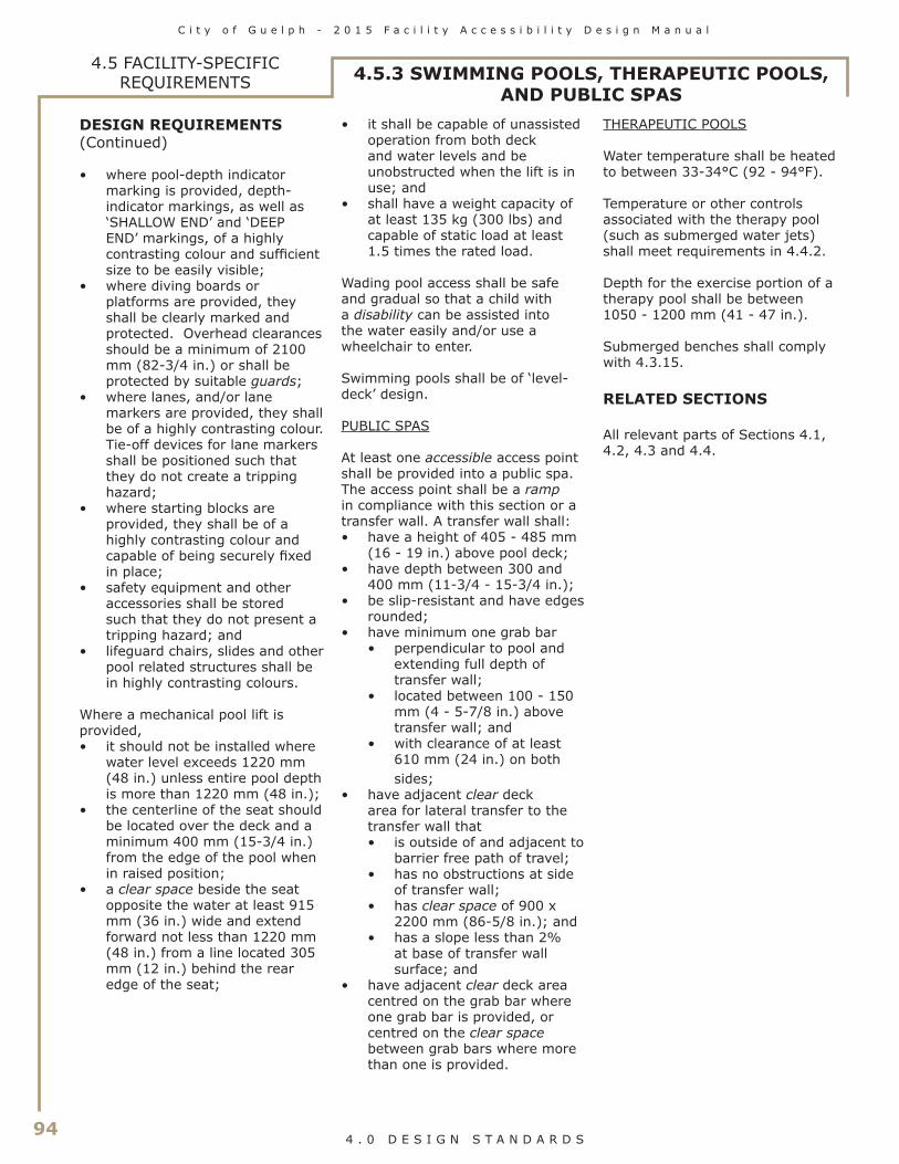
94
C i t y o f G u e l p h - 2 0 1 5 F a c i l i t y A c c e s s i b i l i t y D e s i g n M a n u a l
4 . 0 D E S I G N S T A N D A R D S
4.5 FACILITY-SPECIFIC REQUIREMENTS 4.5.3 SWIMMING POOLS, THERAPEUTIC POOLS,
AND PUBLIC SPASDESIGN REQUIREMENTS(Continued)
• where pool-depth indicator marking is provided, depth- indicator markings, as well as ‘SHALLOW END’ and ‘DEEP END’ markings, of a highly contrasting colour and sufficient size to be easily visible;
• where diving boards or platforms are provided, they shall be clearly marked and protected. Overhead clearances should be a minimum of 2100 mm (82-3/4 in.) or shall be protected by suitable guards;
• where lanes, and/or lane markers are provided, they shall be of a highly contrasting colour. Tie-off devices for lane markers shall be positioned such that they do not create a tripping hazard;
• where starting blocks are provided, they shall be of a highly contrasting colour and capable of being securely fixed in place;
• safety equipment and other accessories shall be stored such that they do not present a tripping hazard; and
• lifeguard chairs, slides and other pool related structures shall be in highly contrasting colours.
Where a mechanical pool lift is provided, • it should not be installed where
water level exceeds 1220 mm (48 in.) unless entire pool depth is more than 1220 mm (48 in.);
• the centerline of the seat should be located over the deck and a minimum 400 mm (15-3/4 in.) from the edge of the pool when in raised position;
• a clear space beside the seat opposite the water at least 915 mm (36 in.) wide and extend forward not less than 1220 mm (48 in.) from a line located 305 mm (12 in.) behind the rear edge of the seat;
• it shall be capable of unassisted operation from both deck and water levels and be unobstructed when the lift is in use; and
• shall have a weight capacity of at least 135 kg (300 lbs) and capable of static load at least 1.5 times the rated load.
Wading pool access shall be safe and gradual so that a child with a disability can be assisted into the water easily and/or use a wheelchair to enter.
Swimming pools shall be of ‘level-deck’ design.
PUBLIC SPAS
At least one accessible access point shall be provided into a public spa. The access point shall be a ramp in compliance with this section or a transfer wall. A transfer wall shall:• have a height of 405 - 485 mm
(16 - 19 in.) above pool deck;• have depth between 300 and
400 mm (11-3/4 - 15-3/4 in.);• be slip-resistant and have edges
rounded;• have minimum one grab bar
• perpendicular to pool and extending full depth of transfer wall;
• located between 100 - 150 mm (4 - 5-7/8 in.) above transfer wall; and
• with clearance of at least 610 mm (24 in.) on both sides;
• have adjacent clear deck area for lateral transfer to the transfer wall that• is outside of and adjacent to
barrier free path of travel;• has no obstructions at side
of transfer wall;• has clear space of 900 x
2200 mm (86-5/8 in.); and• has a slope less than 2%
at base of transfer wall surface; and
• have adjacent clear deck area centred on the grab bar where one grab bar is provided, or centred on the clear space between grab bars where more than one is provided.
THERAPEUTIC POOLS
Water temperature shall be heated to between 33-34°C (92 - 94°F).
Temperature or other controls associated with the therapy pool (such as submerged water jets) shall meet requirements in 4.4.2.
Depth for the exercise portion of a therapy pool shall be between 1050 - 1200 mm (41 - 47 in.).
Submerged benches shall comply with 4.3.15.
RELATED SECTIONS
All relevant parts of Sections 4.1, 4.2, 4.3 and 4.4.

C i t y o f G u e l p h - 2 0 1 5 F a c i l i t y A c c e s s i b i l i t y D e s i g n M a n u a l
95 4 . 0 D E S I G N S T A N D A R D S
4.5 FACILITY-SPECIFIC REQUIREMENTS
RATIONALE
Cafeteria serving lines and seating areas needs to reflect the lower sight lines, reduced reach, knee-space and manoeuvring requirements of persons using wheelchairs or scooters. Patrons using mobility devices may not be able to hold a tray or food items while supporting themselves on canes or manoeuvring a wheelchair. Tray slides should be designed to move trays with a minimum of ease. Features such as colour contrasts and large print menus may assist persons with visual disabilities.
APPLICATION
In addition to the design requirements specified in 4.1 to 4.4, cafeterias shall comply with this section.
Where fixed tables or counters are provided, at least 10%, but not less than one, shall be accessible and shall comply with 4.3.7. It is preferable to have all fixed tables accessible.
In new construction, and where practicable in alterations, the fixed tables (or counters) shall be distributed throughout the space of facility.
At least one lane at each cashier area shall be accessible and comply with this section. It is preferable to have all lanes at all cashier areas accessible.
DESIGN REQUIREMENTS
Where food or drink is served at counters exceeding 865 mm (34 in.) in height for use by customers seated on stools or standing at the counter, a portion of the main counter which is 1525 mm (60 in.) in length (minimum) shall be provided in compliance with 4.3.8, or service shall be available at accessible tables within the same area.
All accessible fixed tables shall be accessible by means of an access aisle at least 1100 mm (43-1/4 in.) clear between parallel edges of tables or between a wall and the table edges.
Dining areas, including raised or sunken dining areas, and outdoor seating areas shall be accessible. In a retrofit situation where it is technically infeasible to provide access to all levels within a dining area, or to all parts of outdoor seating areas, at least one dining area shall be accessible. The accessible area must feature the same level of service and décor as the rest of the dining area and it must not be restricted to use by people with disabilities.
Food service lines shall have a minimum clear width of 1100 mm (43-1/4 in.).
Tray slides shall be mounted no higher than 865 mm (34 in.).
If self-service shelves are provided, at least 50% must be within the reach ranges specified in 4.1.1. It is preferable to have all self-service shelves accessible.
Self-service shelves and dispensing devices for tableware, dishware, condiments, food and beverages shall be installed to comply with 4.1.1.
In banquet rooms or spaces where a head table or speaker’s lectern is located on a raised platform, the platform shall be accessible in compliance with 4.1.9 or 4.1.15, as well as 4.3.3.
Spaces for vending machines, beverage dispensers and other equipment shall comply with 4.1.1 and shall be located on an accessible route in compliance with 4.1.4.
Cashier locations should feature at least one access aisle, which is a minimum of 1100 mm (43-1/4 in.) wide. It is preferable to have all aisles accessible.
Barriers and/or turnstiles, where provided to control access, shall comply with 4.1.7.
Queuing areas shall comply with 4.3.6.
Access to outdoor eating areas shall comply with 4.3.11.
RELATED SECTIONS
All relevant parts of Sections 4.1, 4.2, 4.3 and 4.4.
1370
max
865
max(5
4)
(34)
Figure 4.5.4.1Self Serve Counter
1100 min
(43-1/4)
Figure 4.5.4.2Aisle Width
4.5.4 CAFETERIAS

96
C i t y o f G u e l p h - 2 0 1 5 F a c i l i t y A c c e s s i b i l i t y D e s i g n M a n u a l
4 . 0 D E S I G N S T A N D A R D S
4.5 FACILITY-SPECIFIC REQUIREMENTS 4.5.5 CHURCHES, CHAPELS AND
OTHER PLACES OF WORSHIPRATIONALE
Access to all areas of worship should be provided. Access assumes that persons with disabilities may be participants, leaders, staff or volunteers.
APPLICATION
In addition to the design requirements specified in 4.1 to 4.4, churches, chapels and other places of worship and/or reflection shall comply with this section.
DESIGN REQUIREMENTS
All areas in churches, chapels and other places of worship and/or reflection shall be accessible to persons with disabilities, including main areas of worship, meeting rooms, washrooms, coatrooms and offices.
Accessible seating shall be provided in compliance with 4.3.2.
Pulpits, altars, daises and choir areas shall comply with 4.3.3.
Public address systems shall comply with 4.4.9.
Assistive listening systems shall comply with 4.4.6.
RELATED SECTIONS
All relevant parts of Sections 4.1, 4.2, 4.3 and 4.4.

C i t y o f G u e l p h - 2 0 1 5 F a c i l i t y A c c e s s i b i l i t y D e s i g n M a n u a l
97 4 . 0 D E S I G N S T A N D A R D S
4.5 FACILITY-SPECIFIC REQUIREMENTS4.5.6 LIBRARIES
RATIONALE
Traditional and automated systems should be available to all patrons and staff. Both the design of the facility and the provision of services should be considered. Service counters and study carrels should accommodate the knee-space and armrest requirements of persons using wheelchairs. Computer catalogues, carrels and workstations should be provided at a range of heights, to accommodate persons who are standing or sitting, as well as children of many ages and sizes.
The provision of workstations equipped with assistive technology such as large displays, screen readers, etc. will increase the accessibility of a library.
1100 min(43-1/4)
1100
min
(43-
1/4)
1100
min
(43-
1/4)
Figure 4.5.6.1Aisle Width
APPLICATION
In addition to the design requirements specified in 4.1 to 4.4, libraries shall comply with this section.
Where fixed seating, tables or study carrels are provided, at least 10% but no less than one shall be accessible and in compliance with this section. It is preferable to have all fixed seating, tables and study carrels accessible.
At least one lane at each checkout area shall be accessible and comply with this section. It is preferable to have all lanes at all checkout areas accessible.
Where computer catalogues or workstations are provided, at least 50% shall be accessible and shall comply with this section. It is preferable to have all computer catalogues and workstations accessible.
DESIGN REQUIREMENTS
Accessible fixed seating, tables and study carrels shall be located on an accessible route in compliance with 4.1.4.
Clearances between fixed seating, tables and study carrels shall comply with 4.1.4.
Where shelving is provided at fixed seating, tables or study carrels, the shelving shall be no higher than 1200 mm (47 in.).
Accessible fixed study carrels shall incorporate
• work surfaces and knee/toe clearance in compliance with 4.1.1;
• an electrical outlet; and• lighting levels of at least 100
lux (9.3 ft-candles) at the work surface.
Where provided, traffic control or book security gates shall comply with 4.1.7.

98
C i t y o f G u e l p h - 2 0 1 5 F a c i l i t y A c c e s s i b i l i t y D e s i g n M a n u a l
4 . 0 D E S I G N S T A N D A R D S
4.5.6 LIBRARIES4.5 FACILITY-SPECIFIC
REQUIREMENTS
(27)
(23-5/8)600
685
min
400
1350
(54)
(15-
3/4)
max
imu
m h
igh
reac
h
min
imu
mlo
w re
ach
Figure 4.5.6.2Reach Heights
Figure 4.5.6.3Work Surfaces
DESIGN REQUIREMENTS(Continued)
Minimum clear aisle space at card catalogues and at stacks shall comply with 4.1.1. Aisle configurations shall incorporate a clear floor space allowing a person in a wheelchair to make a 180-degree turn.
Maximum reach heights at card catalogues shall comply with 4.1.1.
Shelf height in stack areas is unrestricted.
Circulation service counters and information service counters shall comply with 4.3.8.
Where provided, computer catalogue or computer workstation shall incorporate
• knee and toe space below in compliance with 4.1.1, and 4.3.7;
• a maximum work surface height of 865 mm (34 in.); and
• a maximum table depth of 900 mm (35 in.).
A minimum of one movable chair shall be provided at every information service counter, computer catalogue or computer workstation.
Book drop slots shall
• be located on an accessible route complying with 4.1.4;
• be located adjacent to a 2440 by 2440 mm (96 by 96 in.) level platform. In a retrofit situation where it is technically infeasible to create a 2440 x 2440 mm (96 by 96 in.) platform, the platform may be reduced to 1525 x 1525 mm (60 by 60 in.); and
• have a slot that is operable using one hand, located between 860 mm (34 in.) and 900 mm (35 in.) above the floor.
Lighting at book stacks shall be mounted directly over the aisle space and provide a minimum of 200 lux (20 ft-candles) at a nominal working height of 920 mm (36 in.).
The acoustic quality shall be free of unnecessary background noise and should permit comprehension by persons with limited hearing. (Refer also to 4.4.16.)
Where CDs tapes, talking books, etc. are available as part of the library resource materials, or for loan purposes, a separate space shall be provided for auditing this material without disturbing other library users.
RELATED SECTIONS
All relevant parts of Sections 4.1, 4.2, 4.3 and 4.4.

C i t y o f G u e l p h - 2 0 1 5 F a c i l i t y A c c e s s i b i l i t y D e s i g n M a n u a l
99 4 . 0 D E S I G N S T A N D A R D S
Total checkout aisles of each design Minimum number of checkout aisles of each design
1-4 1 5-8 2 9-15 3 Over 15 3 plus 20% of additional aisles
Table 4.5.7Required Number of Accessible Checkout Aisles
4.5 FACILITY-SPECIFIC REQUIREMENTS
RATIONALE
The role of persons with disabilities should not be restricted or limited to that of the customer or consumer. Workspaces should be designed with a view to future adaptation or accommodation of individual equipment or assistive devices.
APPLICATION
In addition to the design requirements specified in 4.1 to 4.4, business, mercantile and civic facilities shall comply with this section.
In areas used for transactions where counters have cash registers and are provided for sales and distribution of goods or services to the public, at least one of each type shall have a portion of the counter accessible and in compliance with this section. Such counters shall include, but not be limited to counters in retail stores and distribution centres.
Where counters are dispersed throughout the facility, the accessible counters must also be dispersed throughout the facility.
In public facilities where counters or teller windows have solid partitions or security glazing to separate personnel from the public, at least one of each type shall provide a method to facilitate voice communication. Such methods may include, but are not limited to, grills, slats, talk-through baffles, intercoms or telephone handset devices.
Accessible checkout aisles shall be provided in conformance with Table 4.5.7.
DESIGN REQUIREMENTS
All accessible sales and service counters shall be on an accessible route that complies with 4.1.4.
In areas used for transactions where counters have cash registers and are provided for sales and distribution of goods or services to the public, the counter shall have a portion of the counter that is at least 920 mm (36 in.) in length, with a maximum height of 865 mm (34 in.) above the finished floor.
In areas used for transactions that may not have a cash register but at which goods and services are sold, including, but not limited to, ticketing counters, teller stations, registration counters, information counters, box office counters and library check-out areas either
• a portion of the main counter which is a minimum of 865 mm (34 in.) in length shall be provided with a maximum height of 865 mm (34 in.); or
• an auxiliary counter with a maximum height of 865 mm (34 in.) in close proximity to the main counter shall be provided.
In public facilities where counters or teller windows have solid partitions or security glazing to
separate personnel from the public, the method of communication provided shall be accessible to both individuals who use wheelchairs and individuals who have difficulty bending.
The clear width of accessible checkout lines shall comply with 4.1.4, and the maximum adjoining counter height shall not exceed 965 mm (38 in.) above the finished floor. The top of the lip shall not exceed 1015 mm (40 in.) above the finished floor.
Signage identifying accessible checkout aisles shall incorporate the International Symbol of Access and shall be mounted above the checkout aisle in the same location where the checkout number or type of checkout is displayed.
Any devices used to prevent the removal of shopping carts from store premises shall not prevent access or egress to people in wheelchairs. An alternate entrance that is equally convenient to that provided for ambulatory persons is acceptable.
RELATED SECTIONS
All relevant parts of Sections 4.1, 4.2, 4.3 and 4.4.
4.5.7 BUSINESS, MERCANTILE AND CIVIC

100
C i t y o f G u e l p h - 2 0 1 5 F a c i l i t y A c c e s s i b i l i t y D e s i g n M a n u a l
4 . 0 D E S I G N S T A N D A R D S
4.5 FACILITY-SPECIFIC REQUIREMENTS 4.5.8 POLICE STATIONS
RATIONALE
Police stations should accommodate persons with disabilities, who may be members of the public, detainees, members of counsel or police staff. All areas of the police station that are used by the public, members of staff and counsel should be fully accessible to persons with disabilities. Secure areas, such as cells and common areas used by detainees, should have provisions to accommodate persons with disabilities.
APPLICATION
In addition to the design requirements specified in 4.1 to 4.4, holding cells in police stations shall comply with this section.
Except as specified in this section, all common use areas serving accessible cells or rooms and all public use areas shall be designed and constructed to comply with 4.1 to 4.4.
Exceptions: Requirements for areas of refuge in 4.4.1 do not apply. Compliance with requirements for elevators and stairs is not required in multi-storey housing facilities where accessible cells or rooms, all common use areas serving them and all public use areas are located on an accessible route.
Entrances used by the public, including those that are secured, shall be accessible to comply with 4.1.5.
Exception: Secured entrances, doors and doorways operated only by security personnel shall not be required to have accessible door hardware.
Where security systems are provided at public or other entrances required to be accessible by this section, an accessible route compying with 4.1.4 shall be provided through fixed security barriers at required accessible entrances. Where security barriers incorporate equipment such as metal detectors, fluoroscopes, or other similar devices which cannot
be made accessible, an accessible route shall be provided adjacent to such security screening devices, to facilitate an equivalent circulation path.
In non-contact visiting areas where detainees are separated from visitors, the following elements, where provided, shall be accessible and located on an accessible route complying with 4.1.4.
• Cubicles and Counters: 5%, but not less than one, shall comply with 4.3.7 on both the visitor and detainee sides. Where counters are provided, they shall comply with 4.3.8 on both the visitor and detainee sides.Exception: Non-contact visiting areas not serving accessible cells or rooms.
• Partitions: Solid partitions or security glazing separating visitors from detainees through which communication is necessary shall incorporate communication systems which are accessible to both individuals who use wheelchairs and individuals who have difficulty bending. If such communication systems incorporate a telephone handset, at least one telephone handset shall be equipped with a volume control.
At least 2%, but not less than one, of the total number of cells shall comply with this section. Where special cells are provided (e.g., orientation, protective custody, disciplinary, segregation, detoxification or medical isolation), at least one of each purpose shall comply with this section.
In addition to the aforementioned cell requirements, at least 2%, but not less than one, of general cells shall be equipped with audible emergency warning systems or permanently installed telephones within the cell, in compliance with this section.
Medical care facilities providing physical or medical treatment or care shall be accessible to persons with disabilities.
DESIGN REQUIREMENTS
Accessible cells shall be located on an accessible route in compliance with 4.1.4.
Where provided to serve accessible cells, the following elements or spaces shall be accessible and connected by an accessible route.
• All doors and doorways on an accessible route shall comply with 4.1.6. Exception: Secured entrances, doors and doorways operated only by security personnel shall not be required to have accessible door hardware.
• At least one toilet and one bathing facility shall comply with 4.2.1.
• Accessible beds shall have manoeuvering space at least 920 mm (36 in.) wide along one side.
• At least one drinking fountain and/or water cooler shall comply with 4.3.1.
• Fixed or built-in tables, counters or work surfaces shall comply with 4.3.7.
• At least one fixed bench shall comply with 4.3.15.
• Fixed or built-in storage shall comply with 4.3.9.
• All controls intended for operation by detainees shall comply with 4.4.2.
Where audible emergency warning systems are provided to serve occupants of cells, visual alarms complying with 4.4.4 shall also be provided. Exception: Visual alarms are not required where detainees are not allowed independent means of egress.
Where permanently installed telephones are provided within cells, they shall have volume controls.
RELATED SECTIONS
All relevant parts of Sections 4.1, 4.2, 4.3 and 4.4.

C i t y o f G u e l p h - 2 0 1 5 F a c i l i t y A c c e s s i b i l i t y D e s i g n M a n u a l
101 4 . 0 D E S I G N S T A N D A R D S
4.5 FACILITY-SPECIFIC REQUIREMENTS4.5.9 MUNICIPAL COURTS
RATIONALE
Municipal court facilities should accommodate persons with disabilities, who may be members of the judiciary, court clerks or other officials, defendants, members of counsel and members of the public. Court facilities usually incorporate changes in level at the judge's dais and court officials’ areas. While it is not required to make all of these areas fully accessible, it is a requirement that they be easy to adapt, should the need arise in the future to accommodate a person with a mobility impairment. Other areas of the court generally used by the public, defendants, witnesses and counsel should be accessible to all persons.
APPLICATION
In addition to the design requirements specified in 4.1 to 4.4, municipal courts shall comply with this section.
In addition to the accessible entrances used by staff or the public as required in 4.1.5, where provided, at least one restricted entrance and one secured entrance to the facility shall be accessible. Restricted entrances are those entrances used only by judges, public officials, facility personnel or other authorized parties on a controlled basis. Secure entrances are those entrances to judicial facilities used only by detainees and detention officers.
Exception: Secured entrances, doors and doorways operated only by security personnel shall not be required to have accessible door hardware.
An accessible route complying with 4.1.4 shall be provided through fixed security barriers at required accessible entrances.
Where security barriers incorporate equipment such as metal detectors, fluoroscopes, or other similar devices which cannot be made accessible, an accessible route shall be provided adjacent to such security screening devices, to facilitate an equivalent circulation path.
Where a two-way communication system is provided to gain admittance to a facility, or to restricted areas within a facility, the system shall provide both visual and audible signals and shall comply with 4.4.2.
Where provided, the following elements and spaces shall be on an accessible route complying with 4.1.4.
• Spectator, Press and other areas with Fixed Seats. Each spectator, press and other area with fixed seats having a seating capacity of 25 or less, shall have within its defined area a clear floor space complying with 4.1.1. Where the seating capacity of a spectator, press and other area with fixed seats is greater than 25, seating provision shall be provided in compliance with 4.3.2.
• Jury Boxes and Witness Stands. Each jury box and witness stand shall have within its defined area clear floor space complying with 4.1.1.
• Judges' Benches and Courtroom Stations. Judges' benches, clerks' stations, bailiffs' stations, court reporters' stations, and litigants' and counsel stations shall comply with 4.3.7.
Exceptions:
• Vertical access to raised judges' benches or courtroom stations need not be installed,
provided that the requisite areas and manoeuvering spaces are installed at the time of initial construction, to allow future installation of a means of vertical access complying with 4.1.9, 4.1.14 or 4.1.15 without requiring substantial reconstruction of the space.
• In alterations, accessible wheelchair spaces are not required to be located within the defined area of jury boxes or witness stands and may be located outside these spaces where ramp or lift access poses a hazard by restricting or projecting into a required means of egress.
Permanently installed assistive listening systems in compliance with 4.4.6 shall be provided in each courtroom. The minimum number of receivers shall be 4% of the room occupant load, but not less than two receivers. An informational sign indicating the availability of an assistive listening system shall be posted in a prominent place.
Where provided in areas for jury assembly or deliberation, the following elements or spaces shall be on an accessible route complying with 4.1.4 and shall comply with the following provisions
• refreshment areas, kitchenettes and fixed or built-in refreshment dispensers shall be accessible to persons with disabilities.
• where provided, drinking fountains shall comply with 4.3.1.
RELATED SECTIONS
All relevant parts of Sections 4.1, 4.2, 4.3 and 4.4.

102
C i t y o f G u e l p h - 2 0 1 5 F a c i l i t y A c c e s s i b i l i t y D e s i g n M a n u a l
4 . 0 D E S I G N S T A N D A R D S
4.5 FACILITY-SPECIFIC REQUIREMENTS 4.5.10 TRANSPORTATION FACILITIES
RATIONALE
Links to usable transportation should be accessible to all members of a community. Accessibility within terminals and use of systems should be addressed. This includes public and private bus, taxi, train, and airplane arrival and departure points. A variety of lift devices may need to be accommodated, and alternatives to audio- and/or visual-only scheduling should be available.
APPLICATION
In addition to the design requirements specified in 4.1 to 4.4, transportation facilities located within a site shall comply with this section.
DESIGN REQUIREMENTS
BUS SHELTERS
Bus shelters shall
• be located on firm, level pads approximately at the same elevation as the sidewalk or walkway;
• have clearances around at least two sides of the shelter, including the landing pad side, of at least 1220 mm (48 in.);
• provide a clear view of oncoming traffic;
• incorporate sufficient clear floor space to accommodate a person using a wheelchair or scooter; and
• feature at least one seat with armrests and a seat height between 400 mm and 450 mm (15-3/4 in. and 17-3/4 in.);
All glazed panels surrounding bus shelters shall incorporate decals, and other safety features as specified in 4.1.8.
BUS STOPS
Bus stops shall
• incorporate a paved, firm, level surface, in compliance with local authority standards; and
• not be impeded by adjacent street furniture, such as dispensers, vending machines, waste boxes, planters, posts, signs and guy wires.
TRANSIT TERMINALS
Where bus platforms or other boarding platforms are provided, they shall allow safe access for persons using wheelchairs, and where possible, provide level access into buses.
The edges of platforms shall incorporate a continuous detectable warning surface at least 610 mm (24 in.) deep that complies with 4.4.8.
Lighting levels at all boarding platforms shall be at least 100 lux (10 ft-candles) at the platform or boarding-surface edge.
Boarding locations shall incorporate visible and audible warning signals to advise travellers of approaching vehicles.
Where special lifting devices are used, either on the vehicle or at the boarding point, appropriate manoeuvring space shall be provided around the boarding point for waiting passengers using wheelchairs.
Seating shall be provided in compliance with 4.3.15, at or close to boarding points.
RELATED SECTIONS
All relevant parts of Sections 4.1, 4.2, 4.3 and 4.4.

C i t y o f G u e l p h - 2 0 1 5 F a c i l i t y A c c e s s i b i l i t y D e s i g n M a n u a l
103 4 . 0 D E S I G N S T A N D A R D S
4.5.11 PUBLIC HOUSING4.5 FACILITY-SPECIFIC
REQUIREMENTS
RATIONALE
Persons with disabilities should have equitable access to housing choices. They should also have the opportunity to visit family, neighbours and friends within their homes.
Accessible housing will incorporate features throughout the house to accommodate a family member who uses a wheelchair, scooter or other type of mobility aid.
Visitable housing will incorporate basic access features to accommodate visitors with disabilities, elderly persons or residents who may be temporarity disabled. Basic access includes the ability to enter safely, manoeuvre throughout the entrance-level of the house, and space to access a toilet.
APPLICATION
All public housing units shall be visitable and shall comply with this section.
10% of all public housing units shall be accessible and shall comply with this section.
The common use areas of public housing facilities shall comply with all relevant sections of this manual.
DESIGN REQUIREMENTS
Visitable public housing units shall comply with the 'Visitable dwelling units' section of CAN/CSA B651: Accessible design for the built environment (most current version).
Accessible public housing units shall comply with the 'Accessible dwelling units' section of CAN/CSA B651: Accessible design for the built environment (most current version).
APARTMENT BUILDINGS
In addition to compliance with CSA B651 as noted above, at least 15% of all suites of residential occupancy in an apartment building shall be provided with a accessible path of travel from the suite entrance door into the following rooms and spaces that shall be located at the same level;• at least one bedroom;• at least one bathroom
containing: • a lavatory;• a water closet;• a bathtub or shower;• wall reinforcement to permit
the future installation of grab bars; and
• minimum 1500 mm (59 in.) diameter clear space to allow a wheelchair to turn around;
• a kitchen or kitchen space; and• a living room or space.
The number of suites containing 1, 2 or 3 bedrooms shall be in proportion to the number of suites of residential occupancy having 1, 2 or 3 bedrooms in the remainder of the building.
The accessible suites shall be distributed among storeys that are required to have an accessible path of travel having regard to the height of the suite above grade.
RELATED SECTIONS
All relevant parts of Sections 4.1, 4.2, 4.3 and 4.4.

104
C i t y o f G u e l p h - 2 0 1 5 F a c i l i t y A c c e s s i b i l i t y D e s i g n M a n u a l
4 . 0 D E S I G N S T A N D A R D S
4.5.12 SCHOOLS4.5 FACILITY-SPECIFIC
REQUIREMENTS
RATIONALE
Students, teachers and staff with disabilities should have equitable access to school facilities.
This section of the manual identifies general accessibility requirements that are applicable to all areas of all schools. Additional considerations may be necessary for spaces and/or features specifically designated for the use of students with disabilities - such a special needs classroom or a washroom required to accommodate complex personal care needs.
Students teachers and staff with disabilities should be accommodated in all classrooms and other learning spaces throughout a school. Basic accommodation includes the ability to enter and move freely throughout the space, as well as use the various built-in elements within (i.e. blackboards, switches, computer stations, sinks, etc). Individual students with a disability may require additional accommodations beyond those identified within this section.
Where built-in elements are duplicated within an individual classroom/learning space, such as laboratory benches or pinboards, at least one of each type of element should be accessible to students, teachers and staff with disabilities.
Wherever possible, fixtures, fittings, furniture and equipment should be specified for classrooms and other learning spaces, which is usable by students, teachers and staff with disabilities. However, it is recognized that not all equipment found in classrooms and other learning spaces is usable by persons with disabilities - such as heavy machinery found in trades and technology classrooms.
APPLICATION
All classrooms and other learning spaces shall be accessible and shall comply with this section.
Where built-in elements such as fixed seating, tables or laboratory
benches are provided within a classroom/learning space, at least 10% but no less than one, shall be accessible and in compliance with this section.
At least 50% of shelf space in storage facilities in classroom/learning spaces shall comply with this section.
Classroom 'portables' shall comply with this section.
The common use areas of school facilities shall comply with all relevant sections of this manual.
DESIGN REQUIREMENTS
Classrooms and other learning spaces shall incorporate
• at least one entry/egress door in compliance with 4.1.6;
• floor surfaces throughout in compliance with 4.1.2;
• primary circulation routes in compliance with 4.1.4, linking all functional areas and elements within the space;
• secondary circulation routes no less than 920 mm (36 in.) wide;
• controls and operating mechanisms in compliance with 4.4.2; and
• windows, glazed screens and sidelights in compliance with 4.1.8.
Classrooms, auditoria, assembly areas and other learning spaces that incorporate fixed seating shall
• incorporate accessible seating in compliance with 4.3.2; and
• where applicable, incorporate assistive listening systems in compliance with 4.4.6.
Accessible work surfaces and other built-in elements within classrooms and other learning spaces shall
• comply with 4.3.7;• where applicable, incorporate
controls and operating mechanisms in compliance with 4.4.2; and
• be large enough to accommodate an assistant and extra equipment.
Accessible storage elements within classrooms and other learning spaces shall
• be located on an accessible route with adjacent clear floor space in compliance with 4.1.1;
• comply with at least one of the reach ranges specified in 4.1.1; and
• incorporate operable mechanisms that comply with 4.4.2
At least one blackboard/whiteboard within classrooms and other learning spaces shall
• be located on an accessible route with adjacent clear floor space in compliance with 4.1.1; and
• have its lowest edge located no higher than 760 mm (30 in.).
Where classrooms or other learning spaces incorporate pin boards or other display systems, at least one shall
• be located on an accessible route with adjacent clear floor space in compliance with 4.1.1; and
• have its lowest edge located no higher than 760 mm (30 in.).
Where classrooms or other learning spaces incorporate safety equipment such as fire extinguishers, eye-baths or deluge showers, such equipment shall be accessible to and usable by persons with disabilities.
Where classrooms or other learning spaces incorporate demonstration areas such as laboratory benches, fume cabinets or computer stations, provisions must be made to facilitate viewing from a variety of eye-levels. The installation of mirrors over the demonstation areas is one way to provide such access.
Classrooms and other workspaces intended for general teaching and study shall feature a background noise level no higher than 30 dB(A).
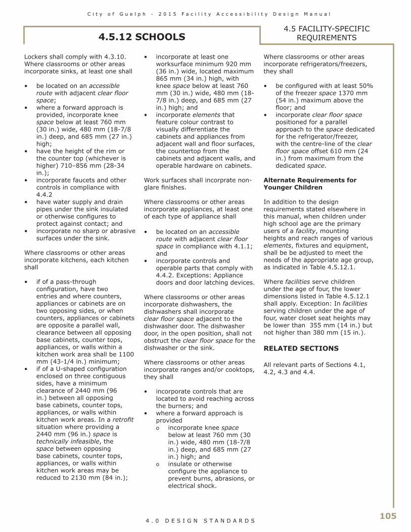
C i t y o f G u e l p h - 2 0 1 5 F a c i l i t y A c c e s s i b i l i t y D e s i g n M a n u a l
105 4 . 0 D E S I G N S T A N D A R D S
4.5.12 SCHOOLS4.5 FACILITY-SPECIFIC
REQUIREMENTS
Lockers shall comply with 4.3.10.Where classrooms or other areas incorporate sinks, at least one shall
• be located on an accessible route with adjacent clear floor space;
• where a forward approach is provided, incorporate knee space below at least 760 mm (30 in.) wide, 480 mm (18-7/8 in.) deep, and 685 mm (27 in.) high;
• have the height of the rim or the counter top (whichever is higher) 710–856 mm (28-34 in.);
• incorporate faucets and other controls in compliance with 4.4.2
• have water supply and drain pipes under the sink insulated or otherwise configures to protect against contact; and
• incorporate no sharp or abrasive surfaces under the sink.
Where classrooms or other areas incorporate kitchens, each kitchen shall
• if of a pass-through configuration, have two entries and where counters, appliances or cabinets are on two opposing sides, or when counters, appliances or cabinets are opposite a parallel wall, clearance between all opposing base cabinets, counter tops, appliances, or walls within a kitchen work area shall be 1100 mm (43-1/4 in.) minimum;
• if of a U-shaped configuration enclosed on three contiguous sides, have a minimum clearance of 2440 mm (96 in.) between all opposing base cabinets, counter tops, appliances, or walls within kitchen work areas. In a retrofit situation where providing a 2440 mm (96 in.) space is technically infeasible, the space between opposing base cabinets, counter tops, appliances, or walls within kitchen work areas may be reduced to 2130 mm (84 in.);
• incorporate at least one worksurface minimum 920 mm (36 in.) wide, located maximum 865 mm (34 in.) high, with knee space below at least 760 mm (30 in.) wide, 480 mm (18-7/8 in.) deep, and 685 mm (27 in.) high; and
• incorporate elements that feature colour contrast to visually differentiate the cabinets and appliances from adjacent wall and floor surfaces, the countertop from the cabinets and adjacent walls, and operable hardware on cabinets.
Work surfaces shall incorprate non-glare finishes.
Where classrooms or other areas incorporate appliances, at least one of each type of appliance shall
• be located on an accessible route with adjacent clear floor space in compliance with 4.1.1; and
• incorporate controls and operable parts that comply with 4.4.2. Exceptions: Appliance doors and door latching devices.
Where classrooms or other areas incorporate dishwashers, the dishwashers shall incorporate clear floor space adjacent to the dishwasher door. The dishwasher door, in the open position, shall not obstruct the clear floor space for the dishwasher or the sink.
Where classrooms or other areas incorporate ranges and/or cooktops, they shall
• incorporate controls that are located to avoid reaching across the burners; and
• where a forward approach is providedo incorporate knee space
below at least 760 mm (30 in.) wide, 480 mm (18-7/8 in.) deep, and 685 mm (27 in.) high; and
o insulate or otherwise configure the appliance to prevent burns, abrasions, or electrical shock.
Where classrooms or other areas incorporate refrigerators/freezers, they shall
• be configured with at least 50% of the freezer space 1370 mm (54 in.) maximum above the floor; and
• incorporate clear floor space positioned for a parallel approach to the space dedicated for the refrigerator/freezer, with the centre-line of the clear floor space offset 610 mm (24 in.) from maximum from the dedicated space.
Alternate Requirements for Younger Children
In addition to the design requirements stated elsewhere in this manual, when children under high school age are the primary users of a facility, mounting heights and reach ranges of various elements, fixtures and equipment, shall be be adjusted to meet the needs of the appropriate age group, as indicated in Table 4.5.12.1.
Where facilities serve children under the age of four, the lower dimensions listed in Table 4.5.12.1 shall apply. Exception: In facilities serving children under the age of four, water closet seat heights may be lower than 355 mm (14 in.) but not higher than 380 mm (15 in.).
RELATED SECTIONS
All relevant parts of Sections 4.1, 4.2, 4.3 and 4.4.

106
C i t y o f G u e l p h - 2 0 1 5 F a c i l i t y A c c e s s i b i l i t y D e s i g n M a n u a l
4 . 0 D E S I G N S T A N D A R D S
4.5.12 SCHOOLS4.5 FACILITY-SPECIFIC
REQUIREMENTS
Element, Fixture or Equipment Ages 4-11 Grades Pre-K - 6
Ages 11-13 Grades 7-8
Frontal approach 1070 mm max. (42 in. max.)
1145 mm max. (45 in. max.)
Reach Ranges
Side approach 1220 mm max. (48 in. max.)
1295 mm max. (51 in. max.)
Ramps and Stairs Top of handrail gripping surface 710 – 865 mm (28 – 34 in.)
760 – 865 mm (30 – 34 in.)
Car control floor buttons - frontal approach
1070 mm max. (42 in. max.)
1145 mm max. (45 in. max.)
Car control floor buttons - side approach
1220 mm max. (48 in. max.)
1295 mm max. (51 in. max.)
Elevators
Emergency communication - highest operable part
1070 mm max. (42 in. max.)
1145 mm max. (45 in. max.)
Platform Lifts Controls and operating mechanisms 710 – 1070 mm (28 – 42 in.)
710 – 1145 mm (28 – 45 in.)
Frontal approach – spout height (to outlet)
810 mm max. (32 in. max.)
865 mm max. (34 in. max.)
Frontal approach – knee clearance 660 mm min. (26 in. min.)
710 mm min. (28 in. min.)
Drinking fountains
Side approach - spout height (to outlet)
810 mm max. (32 in. max.)
865 mm max. (34 in. max.)
Top of seat 355 – 380 mm (14 – 15 in.)
380 – 430 mm (15 – 17 in.)
Grab bars 710 - 760 (28 – 30 in.)
760 - 810 (30 – 32 in.)
Water Closets
Flush controls 1070 mm max. (42 in. max.)
1120 mm max. (44 in. max.)
Rim of urinal 355 mm max. (14 in. max.)
405 mm max. (16 in. max.)
Urinals
Flush controls 1070 mm max. (42 in. max.)
1120 mm max. (44 in. max.)
Rim or counter surface 760 mm max. (30 in. max.)
810 mm max. (32 in. max.)
Knee clearance 660 mm min. (26 in. min.)
710 mm min. (28 in. min.)
Lavatories and Sinks
To faucet from front edge 455 mm max. (18 in. max.)
510 mm max. (20 in. max.)
Mirrors To bottom reflective surface 865 mm max. (34 in. max.)
940 mm max. (37 in. max.)
Top of seat 355 – 380 mm (14 – 15 in.)
380 – 405 mm (15 – 16 in.)
Grab bars 710 - 760 (28 – 30 in.)
760 - 810 (30 – 32 in.)
Hand shower head mounting – frontal approach
1070 mm max. (42 in. max.)
1145 mm max. (45 in. max.)
Shower stalls
Hand shower head mounting – side approach
1220 mm max. (48 in. max.)
1295 mm max. (51 in. max.)
Frontal approach 1070 mm max. (42 in. max.)
1145 mm max. (45 in. max.)
Side approach – distance from wheelchair 0-255 mm (0-10 in.)
1220 mm max. (48 in. max.)
1295 mm max. (51 in. max.)
Storage
Side approach – distance from wheelchair 225-530 mm (10-21 in.)
1070 mm max. (42 in. max.)
1145 mm max. (45 in. max.)
Front approach – highest operable part
1070 mm max. (42 in. max.)
1145 mm max. (45 in. max.)
Controls and Operable Parts
Side approach – highest operable part
1220 mm max. (48 in. max.)
1295 mm max. (51 in. max.)
Front approach – highest operable part
1070 mm max. (42 in. max.)
1145 mm max. (45 in. max.)
Telephones
Side approach – highest operable part
1220 mm max. (48 in. max.)
1295 mm max. (51 in. max.)
Height of tables or counters 710 - 760 (28 – 30 in.)
710 - 810 (28 – 32 in.)
Fixed or Built-in Seating and Tables, Reading and Study Areas, and Work Stations
Knee clearance 660 mm min. (26 in. min.)
710 mm min. (28 in. min.)
Dressing and Fitting Rooms
Top of Bench 355 – 380 mm (14 – 15 in.)
380 – 430 mm (15 – 17 in.)
Food Service Lines Top of tray slide 760 mm max. (30 in. max.)
810 mm max. (32 in. max.)
Table 4.5.12.1Alternate Mounting Height and Reach Range Requirementsfor Facilities where Younger Children are the Primary Users

C i t y o f G u e l p h - 2 0 1 5 F a c i l i t y A c c e s s i b i l i t y D e s i g n M a n u a l
107 4 . 0 D E S I G N S T A N D A R D S
4.5.13 PUBLIC HISTORIC PLACES
Rationale
Providing people of all ages, interests and capacities with broad, general access to public historic places is a highly desirable social goal. It is important to ensure that such access is accompanied by adequate psychological comfort and dignity. Many users of public historic places are the same demographic market that is growing older, becoming less mobile, and often has compromised hearing and vision.
Design solutions that best balance accessibility needs with heritage values are those that enhance the use and appreciation of a property for everyone. Work should be carefully planned and undertaken so that damage to the heritage value and character-defining elements of a public historic place is minimized. The objective is to provide the highest level of access with the lowest level of impact. To determine the most appropriate solutions to access problems, it is recommended that accessibility and conservation specialists, as well as affected users, be consulted early in the planning process. The planning process should begin with an evaluation of the current strengths and weaknesses of the public historic place to identify the quality of existing means of access and wayfinding tools.
Application
The City of Guelph owns and occupies a variety of public historic places, many of which are listed. They include but are not limited to former city halls, early office towers, theatres, swimming pools, fire/paramedic and ambulance stations, and libraries. Workplaces, services and facilities must be adapted so that persons with disabilities can participate in society equitably, and with dignity. For alterations to all public historic places, the Historic Building Committee is required to review the proposal for compliances with the ‘Standards and Guidelines for the Conservation of Historic Places in Canada”.
Design Requirements
In the ‘Standards and Guidelines for the Conservation of Historic Places in Canada’, the following recommendations are proposed for accessibility upgrades to historic places. Please refer to the entire document for further detail.
• Identify the heritage value of the historic place and character-defining elements - materials, forms, location, spatial configurations, uses and cultural associations or meanings - so that required accessibility modifications will not damage or destroy them.
• Comply with accessibility requirements in such a way that character-defining elements are conserved and heritage value maintained.
• Work with accessibility and conservation specialists and affected users to determine the most appropriate solution to access problems that will have the least impact on character-defining elements and overall heritage value.
• Provide accessibility that promotes independence for the disabled person to the highest degree practicable, while conserving the heritage value and character-defining elements.
• Adapt the intervention to its anticipated lifespan, so that short-term improvements remain as reversible as possible.
• Find solutions to meet accessibility requirements that minimize the impact on the historic place and its environment
Related Sections
All relevant parts of Sections 4.1, 4.2, 4.3 and 4.4.
4.5 FACILITY-SPECIFIC REQUIREMENTS

108
C i t y o f G u e l p h - 2 0 1 5 F a c i l i t y A c c e s s i b i l i t y D e s i g n M a n u a l
4 . 0 D E S I G N S T A N D A R D S
4.5.14 FIRE/EMS OFFICES AND WORK AREAS4.5 FACILITY-SPECIFIC
REQUIREMENTS
Rationale
When designing Fire and EMS facilities, the designer shall consider all potential user groups of the facility. This list could include, but is not limited to • Staff returning to light duty work• Injured staff attending a
manager’s office or other meeting space
• Tours of non-work staff (Council members, school groups, etc.)
• Occasional uses of the facility, such as a polling location.
Application
All routes generally used by staff and public and within all areas generally used by staff and public shall comply with this section.
Design Requirements
Through careful consideration to the rationale, application and related sections, combined with a discussion with the FADM review committee, reasonable accessible facilities shall be determined.
Related Sections
All relevant parts of Sections 4.1, 4.2, 4.3 and 4.4.
C i t y o f G u e l p h - 2 0 1 5 F a c i l i t y A c c e s s i b i l i t y D e s i g n M a n u a l
109 5 . 0 I M P L E M E N T A T I O N A N D E N F O R C E M E N T
5.0 IMPLEMENTATION AND ENFORCEMENT
The Facility Accessibility Design Manual shall serve as a Standard for all new construction and renovations in all City facilities owned or leased, as approved by council on October 17, 2005.
During 2012 the City completed a review and update of the 2005 FADM standard at which time a process to address seemingly technically infeasible elements was added. The process is called the FADM Design Checklist and is found within this document in Appendix C. The updated FADM standard and the new review process were presented to Council through information reports during 2011 and 2012.

110
This page intentionally left
blank
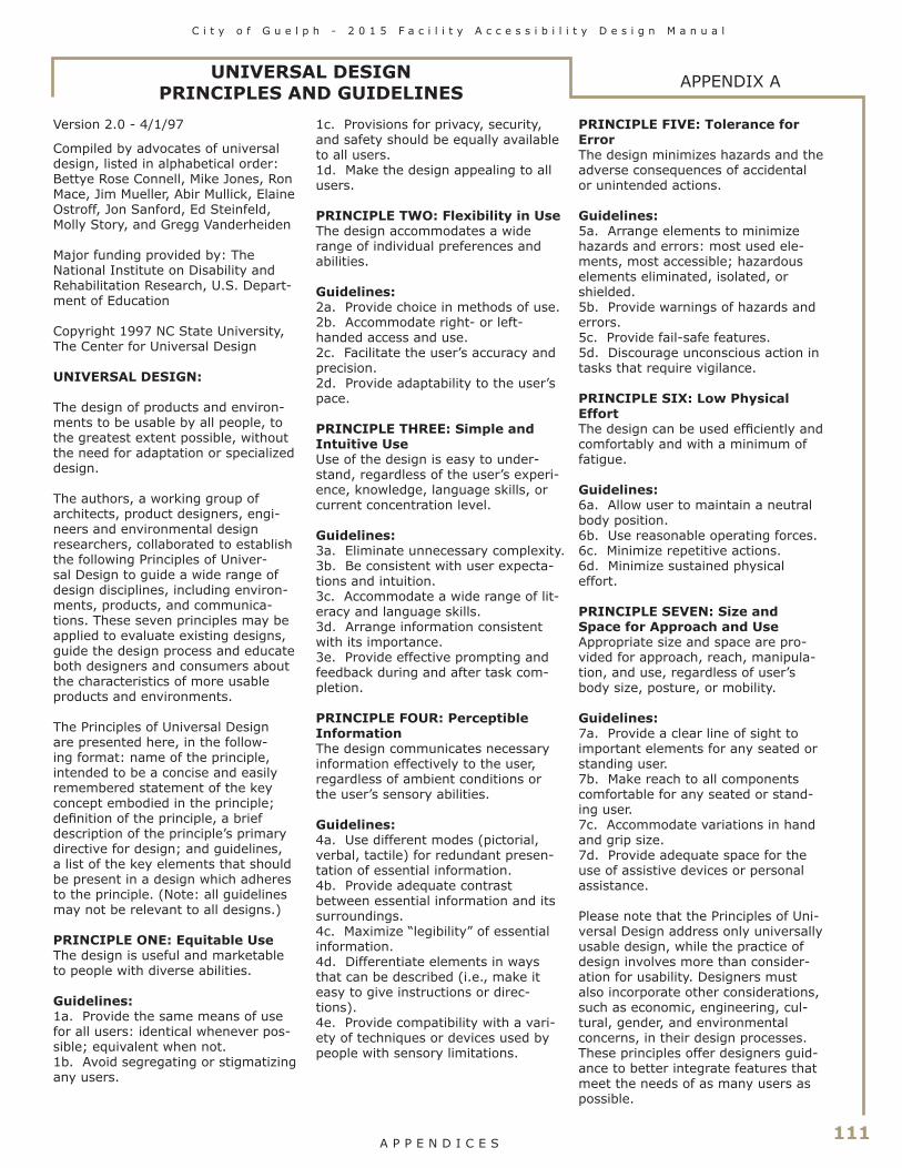
C i t y o f G u e l p h - 2 0 1 5 F a c i l i t y A c c e s s i b i l i t y D e s i g n M a n u a l
111 A P P E N D I C E S
UNIVERSAL DESIGN PRINCIPLES AND GUIDELINES
APPENDIX A
Version 2.0 - 4/1/97
Compiled by advocates of universal design, listed in alphabetical order: Bettye Rose Connell, Mike Jones, Ron Mace, Jim Mueller, Abir Mullick, Elaine Ostroff, Jon Sanford, Ed Steinfeld, Molly Story, and Gregg Vanderheiden
Major funding provided by: The National Institute on Disability and Rehabilitation Research, U.S. Depart-ment of Education
Copyright 1997 NC State University, The Center for Universal Design
UNIVERSAL DESIGN:
The design of products and environ-ments to be usable by all people, to the greatest extent possible, without the need for adaptation or specialized design.
The authors, a working group of architects, product designers, engi-neers and environmental design researchers, collaborated to establish the following Principles of Univer-sal Design to guide a wide range of design disciplines, including environ-ments, products, and communica-tions. These seven principles may be applied to evaluate existing designs, guide the design process and educate both designers and consumers about the characteristics of more usable products and environments.
The Principles of Universal Design are presented here, in the follow-ing format: name of the principle, intended to be a concise and easily remembered statement of the key concept embodied in the principle; definition of the principle, a brief description of the principle’s primary directive for design; and guidelines, a list of the key elements that should be present in a design which adheres to the principle. (Note: all guidelines may not be relevant to all designs.)
PRINCIPLE ONE: Equitable UseThe design is useful and marketable to people with diverse abilities.
Guidelines: 1a. Provide the same means of use for all users: identical whenever pos-sible; equivalent when not.1b. Avoid segregating or stigmatizing any users.
1c. Provisions for privacy, security, and safety should be equally available to all users.1d. Make the design appealing to all users.
PRINCIPLE TWO: Flexibility in UseThe design accommodates a wide range of individual preferences and abilities.
Guidelines: 2a. Provide choice in methods of use.2b. Accommodate right- or left-handed access and use.2c. Facilitate the user’s accuracy and precision.2d. Provide adaptability to the user’s pace.
PRINCIPLE THREE: Simple and Intuitive UseUse of the design is easy to under-stand, regardless of the user’s experi-ence, knowledge, language skills, or current concentration level.
Guidelines: 3a. Eliminate unnecessary complexity.3b. Be consistent with user expecta-tions and intuition.3c. Accommodate a wide range of lit-eracy and language skills.3d. Arrange information consistent with its importance.3e. Provide effective prompting and feedback during and after task com-pletion.
PRINCIPLE FOUR: Perceptible InformationThe design communicates necessary information effectively to the user, regardless of ambient conditions or the user’s sensory abilities.
Guidelines: 4a. Use different modes (pictorial, verbal, tactile) for redundant presen-tation of essential information.4b. Provide adequate contrast between essential information and its surroundings.4c. Maximize “legibility” of essential information.4d. Differentiate elements in ways that can be described (i.e., make it easy to give instructions or direc-tions).4e. Provide compatibility with a vari-ety of techniques or devices used by people with sensory limitations.
PRINCIPLE FIVE: Tolerance for ErrorThe design minimizes hazards and the adverse consequences of accidental or unintended actions.
Guidelines: 5a. Arrange elements to minimize hazards and errors: most used ele-ments, most accessible; hazardous elements eliminated, isolated, or shielded.5b. Provide warnings of hazards and errors.5c. Provide fail-safe features.5d. Discourage unconscious action in tasks that require vigilance.
PRINCIPLE SIX: Low Physical EffortThe design can be used efficiently and comfortably and with a minimum of fatigue.
Guidelines: 6a. Allow user to maintain a neutral body position.6b. Use reasonable operating forces.6c. Minimize repetitive actions.6d. Minimize sustained physical effort.
PRINCIPLE SEVEN: Size and Space for Approach and UseAppropriate size and space are pro-vided for approach, reach, manipula-tion, and use, regardless of user’s body size, posture, or mobility.
Guidelines: 7a. Provide a clear line of sight to important elements for any seated or standing user.7b. Make reach to all components comfortable for any seated or stand-ing user.7c. Accommodate variations in hand and grip size.7d. Provide adequate space for the use of assistive devices or personal assistance.
Please note that the Principles of Uni-versal Design address only universally usable design, while the practice of design involves more than consider-ation for usability. Designers must also incorporate other considerations, such as economic, engineering, cul-tural, gender, and environmental concerns, in their design processes. These principles offer designers guid-ance to better integrate features that meet the needs of as many users as possible.
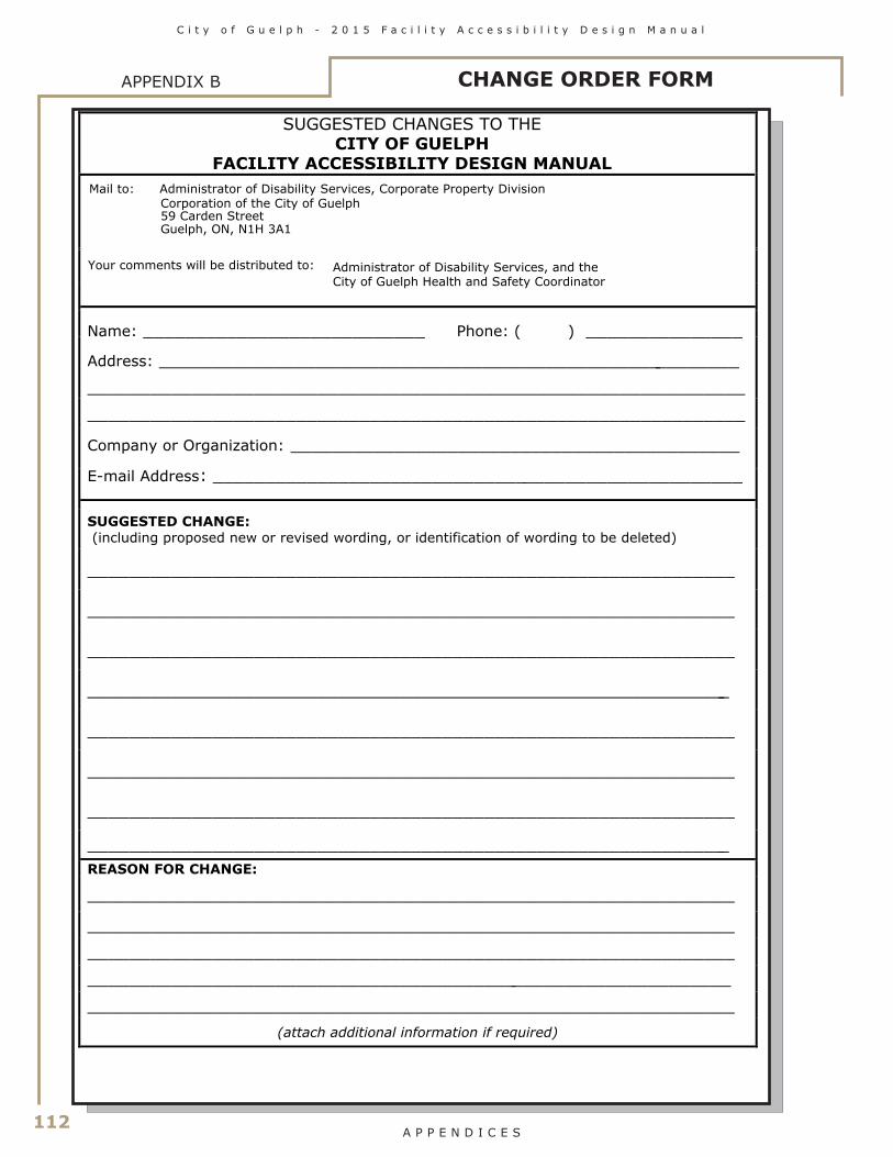
112
C i t y o f G u e l p h - 2 0 1 5 F a c i l i t y A c c e s s i b i l i t y D e s i g n M a n u a l
A P P E N D I C E S
APPENDIX B
SUGGESTED CHANGES TO THECITY OF GUELPH
FACILITY ACCESSIBILITY DESIGN MANUAL
Mail to: Administrator of Disability Services, Corporate Property Division Corporation of the City of Guelph 59 Carden Street
Guelph, ON, N1H 3A1
Name: ___________________________ Phone: ( ) _______________
Address: ________________________________________________________
_______________________________________________________________
_______________________________________________________________
Company or Organization: ___________________________________________
E-mail Address: ___________________________________________________
SUGGESTED CHANGE: (including proposed new or revised wording, or identification of wording to be deleted)
______________________________________________________________
______________________________________________________________
______________________________________________________________
______________________________________________________________
______________________________________________________________
______________________________________________________________
______________________________________________________________
______________________________________________________________ REASON FOR CHANGE: ______________________________________________________________
______________________________________________________________ ______________________________________________________________ ______________________________________________________________ ______________________________________________________________
(attach additional information if required)
Administrator of Disability Services, and the City of Guelph Health and Safety Coordinator
Your comments will be distributed to:
CHANGE ORDER FORM

C i t y o f G u e l p h - 2 0 1 5 F a c i l i t y A c c e s s i b i l i t y D e s i g n M a n u a l
113 A P P E N D I C E S
APPENDIX CFADM DESIGN CHECKLIST
City of Guelph FADM DESIGN CHECKLIST Project Name:
Project Number:
Project Type:
Project Phase: □ New Construction
□ Preliminary (Conceptual) □ Renovation/Alteration
□ Design Development □ Exterior Only
□ Other (Please Specify) □ Other (Please Specify) The City of Guelph Facility Accessibility Design Manual is a mandatory design aid, applicable to the design and construction of new facilities, as well as the retrofit, alteration or addition to existing facilities owned, leased or operated by the City of Guelph. This Design Checklist has been developed to assist staff, designers and contracted consultants with the application of FADM to ensure that each element has been applied to each project, and to document elements of a project that may be technically infeasible to implement. In a retrofit situation where a design element has little likelihood of being accomplished due to structural conditions or other physical or site contraints prohibit modification, the TECHNICAL INFEASIBILITY JUSTIFICATION FORM shall be completed by the designer and forwarded to the City Project Manager and Accessibility Coordinator. Where an equivalent means of facilitation is being proposed to achieve the intent of part of the Standards, an EQUIVALENT FACILITATION PROPOSAL FORM shall be completed by the designer and forwarded to the City Project Manager and Accessibility Coordinator. This checklist is a reference tool only and must be used in conjunction with the FADM document. The consultant shall complete this checklist during the design phase of each project, and submit to the City Project Manager.

114
C i t y o f G u e l p h - 2 0 1 5 F a c i l i t y A c c e s s i b i l i t y D e s i g n M a n u a l
A P P E N D I C E S
FADM DESIGN CHECKLISTAPPENDIX C
SITE DESIGNFADM Element/System Compliance StatusReference Y N Comments or N/A4.1.2 Ground and Floor Surfaces4.1.3 Protruding/ Overhead Objects4.1.4 Accessible Routes4.1.5 Entrances4.1.9 Ramps4.1.10 Curb Ramps4.1.11 Stairs4.1.12 Handrails4.3.11 Balconies, Porches, Terraces
and Patios4.3.12 Parking4.3.13 Passenger Loading Zones4.3.14 Landscaping Materials and
Planting4.3.15 Benches4.3.16 Public Use Eating Areas4.3.17 Street Furniture4.4.3 Vending and Ticketing
Machines4.4.7 Signage4.4.8 Detectable Warning Surfaces4.4.12 Glare and Light Sources4.4.13 Lighting4.4.14 Materials and Finishes4.4.15 Texture and Colour4.4.17 Pedestrian Signals4.5.2 Outdoor Recreation Facilities4.5.10 Transportation Facilities4.5.13 Public Historic Places

C i t y o f G u e l p h - 2 0 1 5 F a c i l i t y A c c e s s i b i l i t y D e s i g n M a n u a l
115 A P P E N D I C E S
APPENDIX CFADM DESIGN CHECKLIST
BUILDING DESIGNFADM Element/System Compliance StatusReference Y N Comments or N/AAccess and Circulation4.1.2 Ground and Floor Surfaces4.1.3 Protruding/ Overhead Objects4.1.4 Accessible Routes4.1.5 Entrances4.1.6 Doors4.1.7 Gates, Turnstiles & Openings4.1.8 Windows, Screens, Sidelights4.1.9 Ramps4.1.10 Curb Ramps4.1.11 Stairs4.1.12 Handrails4.1.13 Escalators4.1.14 Elevators4.1.15 Platform Lifts4.3.12 Parking4.3.13 Passenger Loading Zones4.3.14 Landscaping 4.3.15 Benches4.3.16 Public Use Eating Areas4.3.17 Street FurnitureWashroom Facilities4.2.1 Toilet and Bathing Facilities4.2.2 Toilet Stalls4.2.3 Toilets4.2.4 Lavatories4.2.5 Urinals4.2.6 Washroom Accessories4.2.7 Individual Washrooms4.2.8 Bathtubs4.2.9 Shower Stalls4.2.10 Grab Bars

116
C i t y o f G u e l p h - 2 0 1 5 F a c i l i t y A c c e s s i b i l i t y D e s i g n M a n u a l
A P P E N D I C E S
BUILDING DESIGNFADM Element/System Compliance StatusReference Y N Comments or N/AOther Amenities4.3.1 Drinking Fountains4.3.2 Viewing Positions4.3.3 Elevated Platforms4.3.4 Dressing Rooms4.3.5 Offices, Work Areas, Meeting
Rooms4.3.6 Waiting and Queuing Areas4.3.7 Tables, Counters, Work Surfaces4.3.8 Information, Reception and
Service Counters4.3.9 Storage Shelving and Display 4.3.10 Lockers4.3.11 Balconies, Porches, Terraces,
Patios4.3.15 Benches4.3.16 Public Use Eating AreasSystems and Controls4.4.1 Emergency Systems4.4.2 Controls, Operating Mechanisms4.4.3 Vending & Ticketing Machines4.4.4 Visual Alarms4.4.5 Public Telephones4.4.6 Assistive Listening Systems4.4.7 Signage4.4.8 Detectable Warning Surfaces4.4.9 Public Address Systems4.4.10 Information Systems4.4.11 Card Access, Safety, Security 4.4.12 Glare and Light Sources4.4.13 Lighting4.4.14 Materials and Finishes4.4.15 Texture and Colour4.4.16 Acoustics4.4.17 Pedestrian Signals
FADM DESIGN CHECKLISTAPPENDIX C
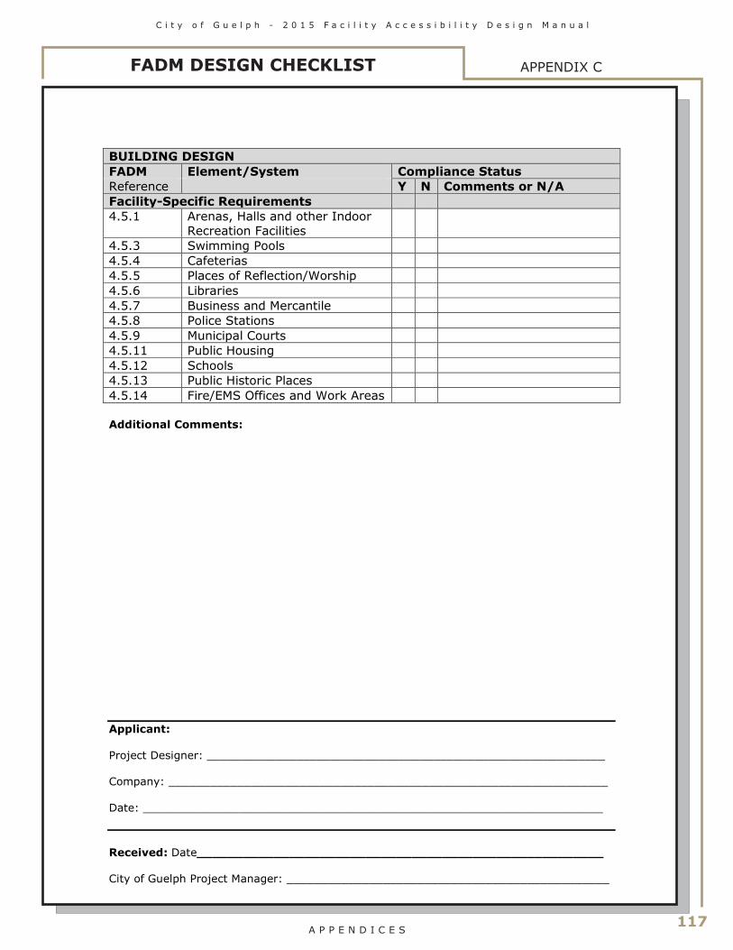
C i t y o f G u e l p h - 2 0 1 5 F a c i l i t y A c c e s s i b i l i t y D e s i g n M a n u a l
117 A P P E N D I C E S
APPENDIX CFADM DESIGN CHECKLIST
BUILDING DESIGNFADM Element/System Compliance StatusReference Y N Comments or N/AFacility-Specific Requirements4.5.1 Arenas, Halls and other Indoor
Recreation Facilities4.5.3 Swimming Pools4.5.4 Cafeterias4.5.5 Places of Reflection/Worship4.5.6 Libraries4.5.7 Business and Mercantile4.5.8 Police Stations4.5.9 Municipal Courts4.5.11 Public Housing4.5.12 Schools4.5.13 Public Historic Places4.5.14 Fire/EMS Offices and Work Areas
Additional Comments:
Applicant:
Project Designer: __________________________________________________________
Company: ________________________________________________________________
Date: ___________________________________________________________________
Received: Date_____________________________________________________
City of Guelph Project Manager: _______________________________________________
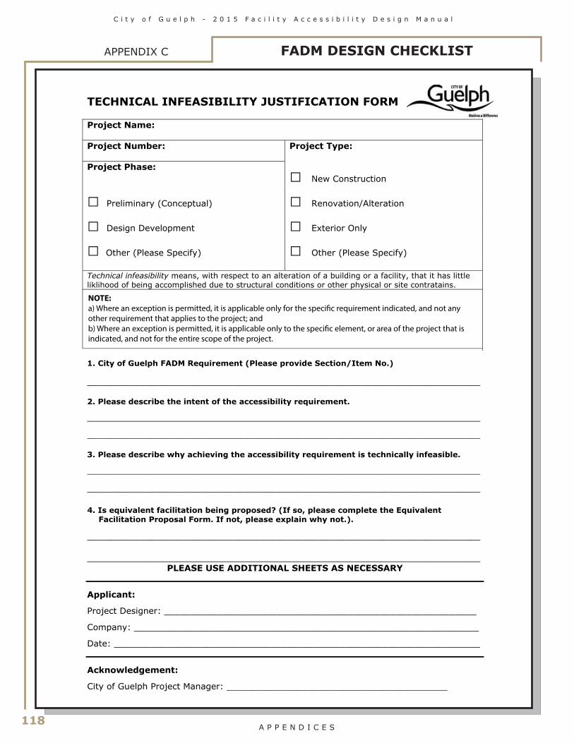
118
C i t y o f G u e l p h - 2 0 1 5 F a c i l i t y A c c e s s i b i l i t y D e s i g n M a n u a l
A P P E N D I C E S
FADM DESIGN CHECKLISTAPPENDIX C
TECHNICAL INFEASIBILITY JUSTIFICATION FORM Project Name:
Project Number:
Project Type:
Project Phase: □ New Construction
□ Preliminary (Conceptual) □ Renovation/Alteration
□ Design Development □ Exterior Only
□ Other (Please Specify) □ Other (Please Specify)
Technical infeasibility means, with respect to an alteration of a building or a facility, that it has little liklihood of being accomplished due to structural conditions or other physical or site contratains.
1. City of Guelph FADM Requirement (Please provide Section/Item No.)
_________________________________________________________________________ 2. Please describe the intent of the accessibility requirement. _________________________________________________________________________ _________________________________________________________________________ 3. Please describe why achieving the accessibility requirement is technically infeasible. _________________________________________________________________________ _________________________________________________________________________ 4. Is equivalent facilitation being proposed? (If so, please complete the Equivalent
Facilitation Proposal Form. If not, please explain why not.). _________________________________________________________________________ _________________________________________________________________________
PLEASE USE ADDITIONAL SHEETS AS NECESSARY
Applicant:
Project Designer: __________________________________________________________ Company: ________________________________________________________________ Date: ____________________________________________________________________ Acknowledgement: City of Guelph Project Manager: _________________________________________
NOTE: a) Where an exception is permitted, it is applicable only for the speci�c requirement indicated, and not any other requirement that applies to the project; andb) Where an exception is permitted, it is applicable only to the speci�c element, or area of the project that is indicated, and not for the entire scope of the project.

C i t y o f G u e l p h - 2 0 1 5 F a c i l i t y A c c e s s i b i l i t y D e s i g n M a n u a l
119 A P P E N D I C E S
EQUIVALENT FACILITATION PROPOSAL FORM Project Name:
Project Number:
Project Type:
Project Phase: □ New Construction
□ Preliminary (Conceptual) □ Renovation/Alteration
□ Design Development □ Exterior Only
□ Other (Please Specify) □ Other (Please Specify) 1. City of Guelph FADM Requirement (Please provide Section/Item No.) _________________________________________________________________________ 2. Please describe the intent of the accessibility requirement. _________________________________________________________________________ _________________________________________________________________________ 3. Please describe your reasons for proposing an alternate design. _________________________________________________________________________ _________________________________________________________________________ 4. Please describe how your proosed alternate design meets the intent of the accessibility
requirement of the City of Guelph FADM. _________________________________________________________________________ _________________________________________________________________________
PLEASE USE ADDITIONAL SHEETS AS NECESSARY
Applicant:
Project Designer: ___________________________________________________________ Company: ________________________________________________________________ Date: ____________________________________________________________________ Acknowledgement: City of Guelph Project Manager: _______________________________________________
APPENDIX CFADM DESIGN CHECKLIST

120
C i t y o f G u e l p h - 2 0 1 5 F a c i l i t y A c c e s s i b i l i t y D e s i g n M a n u a l
A P P E N D I C E S
FADM DESIGN REVIEW PROCESSAPPENDIX D
FADM Review and Alternate Design Review Process
Consultant to provide:1. Project Documents; and
2. Completed Checklist
City of Guelph Project Manager
Maintains Checklist and Attaches to Commissioning Documents
City of Guelph Accessibility Coordinator
Advice / Alternate Design Review Process Coordination
City of Guelph Alternate Design Review Committee
Outcome: Recommendation to Executive Team
City of GuelphManager-Partnerships and Inclusion
Alternate Design From FADM Requested
ProceedConsultant to Alter Drawings
According to Direction
InCompliance
With FADM?
Yes
No
Executive Team Outcome: Provide direction to
Project Manager and Consultant