facility wide permit for ferro corporation · 2001-08-06 · facility wide permit for ferro...
TRANSCRIPT

TOC1
FACILITY WIDE PERMIT for Ferro Corporation
Table of ContentsI. Permit Page
II. Fact Sheet
1. Name and Address of Applicant
2. Name and Address of Facility Covered by Permit Application
3. Permitted ActivitiesA. Description of Permit Replacement ActivitiesB. Description of Monitoring/Reporting
4. Facility DescriptionA. Narrative DescriptionB. General Flow Diagram
5. Basis for Facility Level Multimedia ReleasesA. Pollution Prevention PlanB. Facility Level Multimedia ReleasesC. Surface Water LimitsD. GroundwaterE. NOx/RACT for BoilersF. VOC/RACT
6. Procedures for Reaching a Final Decision on the Draft Permit
7. NJDEP Contact
III. General Air Facility ConditionsA. Appeal RightsB. Modification of Facility-Wide PermitC. General ConditionsD. Recordkeeping, Monitoring and ReportingE. Facility-Level Release InformationF. Facility Wide Risk Analysis
IV: General Facility Conditions for Water Quality
A. Appeal RightsB. Modification of Facility-Wide PermitC. General ConditionsD. Recordkeeping, Monitoring and ReportingE. Inspections
V. General Hazardous Waste Facility ConditionsA. Duty to ComplyB. Duty to reapplyC. Need to Halt or Reduce Activity Not a DefenseD. Need to MitigateE. Proper Operation and MaintenanceF. Permit ActionsG. Property Rights

TOC2
H. Duty to Provide InformationI. Inspection and EntryJ. Monitoring and RecordsK. Signatory RequirementsL. Reporting RequirementsM. Permit Modification or Revocation and ReissuanceN. Personnel TrainingO. Preparedness and PreventionP. Contingency PlanQ. SecurityR. Termination of a PermitS. Operating RecordT. Permit LimitationsU. Financial RequirementsV. Compliance with Other State Regulations and StatutesW. Submission of Documents Required by Permit Conditions
VI. Process Packages*A. Benzyl Chloride ProcessB. TCPA ProcessC. Phosphate Esters ProcessD. Benzyl Phthalates ProcessE. UtilitiesF. Wastewater Treatment Plant (WWTP)G. Boiler
1. Administrative Information
A. Process DescriptionB. Block Flow Diagrams
AR - Air ReleaseSW - Solid WasteWW - WastewaterDashed Lines signify Nonproduct Output Generation Points
C. Equipment, Control Device, and Source Sheet InformationD. Source Control Data SheetsE. Process Stack Sheet InformationF. Raw Material/Contaminant List
2. Technical Information - Release and Alteration/Amendment LimitsA. Process (Tons/Year)B. Worst Case Permit Allowable Emissions Limits Per Source (Pounds/Hour)C. Lb/Product Emission Limits (Not for WTP, WWTP, or Boiler)
3. Compliance PlanA. Applicable RequirementsB. Recordkeeping, Monitoring, and ReportingC. Special Conditions
* Each of the 7 process packages has this general format.

SECTION I: FACILITY WIDE PERMIT COVER PAGE
Issued To: Ferro CorporationUS Route 130 SouthBridgeport, New Jersey 08014
Location: US Route 130 SouthBridgeport, New Jersey
Permit Number: NJ00012Issuance Date: April 22, 1999Effective Date: June 1, 1999Expiration Date: June 1, 2004
This Facility-Wide Permit is being issued in accordance with N.J.S.A. 13:1D-35 et seq., particularly N.J.S.A. 13:1D-48, N.J.A.C. 7:1K et seq., N.J.S.A. 13:1E-1 et seq., N.J.A.C. 7:26 et seq., N.J.A.C. 7:26G et seq. N.J.S.A. 58:10A-1et seq., N.J.A.C. 7:14A et seq., N.J.S.A. 26:2C-1 et seq., N.J.A.C. 7:27 et seq., and N.J.S.A. 58:1A-1 et. seq.,N.J.A.C. 7:19-1 et. seq. The FWP will replace the following existing permits/certificates listed below.
i) Renewal of New Jersey Pollutant Discharge Elimination System (NJPDES) permit No. 5045 for processand storm water discharges and deletion of the Groundwater NJPDES permit No. 5045.
ii) Air Pollution Control Certificates listed in Attachment B and any others issued under ID 55049 or55707;
iii) Renewal of Hazardous Waste Storage Permit, New Jersey Hazardous Waste Facility Permit No.0809A1HP03, EPA ID No. 001 700 707
iv) Renewal of Water Allocation Permit No. 2099P
The FWP contains provisions covering the following monitoring and reporting requirements:
i) Emission reporting and tracking requirements pursuant to N.J.A.C. 7:27, Air Pollution Control;
ii) Recordkeeping and reporting of monitoring results pursuant to N.J.A.C. 7:14A-2.9;
iii) Submittal of New Jersey Pollution Prevention and Release Reports pursuant to N.J.A.C. 7:1K-5.1 and6.1;
iv) Submittal of a biennial report by March 1 of each even numbered year covering hazardous wastegenerators activities during the previous calendar years pursuant to 40 CFR 264.75.
v) Submittal of quarterly diversion reports, DWR-017A, pursuant to the Water Supply Allocation Rules,N.J.A.C. 7:19-2.14.
_Signed by Administrator Signed by DirectorAdministrator DirectorNJDEP, Air Quality Regulation NJDEP, Division of Water Quality
Signed by John A. Castner, P.E. P.P., Director Signed by AdministratorDirector AdministratorNJDEP, Division of Solid and Hazardous NJDEP, Water Supply Administration
Modified 11/28/00

FS1
SECTION II: FACT SHEET
1: Name and Address of Applicant
Ferro CorporationUS Route 130 SouthPO Box 309Bridgeport, New Jersey, 08014
2. Name and Address of Facility Covered by Application
Same
3. Permitted Activities
A) This Facility-Wide Permit is being issued in accordance with N.J.S.A. 13:1D-35 et seq.,particularly N.J.S.A. 13:1D-48, N.J.A.C. 7:1K et seq., N.J.S.A. 13:1E-1 et seq., N.J.A.C. 7:26 etseq., N.J.A.C. 7:26G et seq. N.J.S.A. 58:10A-1 et seq., N.J.A.C. 7:14A et seq., N.J.S.A. 26:2C-1et seq., N.J.A.C. 7:27 et seq., and N.J.S.A. 58:1A-1 et. seq., N.J.A.C. 7:19-1 et. seq. The FWPwill replace the following existing permits/certificates listed below.
i) Renewal of New Jersey Pollutant Discharge Elimination permit No. 5045 for process and stormwater discharges.
ii) Air Pollution Control Certificates listed in Attachment B;
iii) Renewal of Hazardous Waste Storage Permit, New Jersey Hazardous Waste Facility PermitNo. 0809A1HP03, EPA ID No. 001 700 707
iv) Renewal of Water Allocation Permit No. 2099P
B) The FWP contains provisions covering the following monitoring and reporting requirements:
i) Emission reporting and tracking requirements pursuant to N.J.A.C. 7:27, Air PollutionControl;
ii) Recordkeeping and reporting of monitoring results pursuant to N.J.A.C. 7:14A-2.9;
iii) Submittal of New Jersey Pollution Prevention and Release Reports pursuant to N.J.A.C. 7:1K-5.1 and 6.1;
iv) Submittal of a biennial report by March 1 of each even numbered year covering hazardouswaste generators activities during the previous calendar years pursuant to 40 CFR 264.75.
v) Submittal of quarterly diversion reports, DWR-017A, pursuant to the Water Supply AllocationRules, N.J.A.C. 7:19-2.14.
4. Facility Description
A. Narrative Description
The applicant is a chemical manufacturer involved primarily in the manufacturing of organicintermediates and is classified in Standard Industrial Classification (SIC) Code 2869. Siteoperations have been identified into seven different processes that have the potential to releasecontaminants into the air, land, and waters of the State.

FS2
Modified 8/17/00There are four production processes making tetrathal, benzyl chloride, phosphate esters, andbenzyl phthalates. The benzyl chloride also produces hydrochloric acid as a sellable commodity.The benzyl phthalate process uses a portion of the benzyl chloride as an input. Additionally,some weak hydrochloric acid generated in the phosphate esters process is used for neutralizationin the waste water treatment plant(WWTP). In general, all four of the production processes gothrough a storage step, a reaction step, and a recovery/refinement/packaging step. The facility’swater treatment plant is used to process well water to use on site. Steam is supplied to theprocess from the Logan Co-generation plant. The on-site boiler will only be used when theneighboring CO-GEN is down and for weekly startup to insure operation. The WWTP is used totreat receiving wastewater from the four processes and the boiler. It also has the capacity to treatstormwater and spill contained material. The WWTP will also be authorized to receiveleachate from the former on-site landfill (currently owned and operated by Solutia Inc.) andwastewater from any ongoing cleanup operations except from PDA #1, by Ferro, SolutiaInc. or their successors. However, at this time, these activities are not being performed.
This FWP permits the release of air pollutants from significant air emission sources, thedischarge from the WWTP, one other stormwater discharge, and the storage of hazardouswaste in one tank and a container storage area.
B. General Flow Diagram
Wastewater Treatment PlantPhosphate Esters
Manufacturing
Tetrathal Manufacturing
Benzyl Phthalate Manufacturing
Benzyl Chloride Manufacturing
Boilers
Water Treatment Plant
5. Basis for Facility-level Multimedia Permit Conditions
A. Pollution Prevention Plan
The applicant has prepared a Pollution Prevention Plan (Plan) pursuant to the PollutionPrevention Rules, N.J.A.C. 7:1K 1.1 et seq. The plan includes a comprehensive analysis of theuse and generation of 17 listed hazardous substances and 22 other substances in the affectedprocesses. The 17 listed substances are the same as those reported on the Federal Toxic ReleaseInventory (TRI). The additional 22 substances were included as part of a more thorough reviewof the facility. Take note that the flow diagrams in the production process packages that followhave dashes on them. The dashed lines represent points of nonproduct generation and areintegrally connected to the pollution plan prepared by the facility.
B. Facility Level Multimedia Releases
Facility-level air emissions for Volatile Organic Compounds (VOCs), Total SuspendedParticulates (TSPs), Particulate Matter Less Than 10 Microns (PM-10), Oxides of Nitrogen(NOx), Carbon Monoxide (CO), and Sulfur Dioxide (SO2)are based in part on compliance with

FS3
Modified 11/28/00

FS4
N.J.A.C. 7:27-18.1 et. seq. ”Control and Prohibition of Air Pollution from New or AlteredSources Affecting Ambient Air Quality,” more commonly referred to as the “Emission OffsetRules.” These rules require covered major sources to determine if proposed emission increasesare a “significant net emission increase.” If so, the facility is required to purchase offsets andimplement technology representing the Lowest Achievable Emission Rate (LAER). Informationcontained in existing Air Pollution Control (APC) permits, the FWP application and thePollution Prevention Plan was used to construct the attached Facility Release Summary Table inSection III. E., which is the equivalent of an emission offset analysis pursuant to N.J.A.C. 7:27-18.7. This information shows that there are no significant net emission increases based on thenew emission limits proposed in the facility-wide permit. The emissions contained in the finalFWP will establish the baseline for the next five year contemporaneous period to be used todetermine the applicability of the “Emission Offset Rules” should any additional emissionincreases occur during this five year period.
C. Surface Water Limits
A statement of basis has been developed to demonstrate how a limit was determined and whatsampling for that limit is required. The statement of basis is included in the body of the permit.
D. Groundwater Limits
Sampling of groundwater requirements are not included as part of this permit. The Bureau ofState Case management and USEPA Region II are preparing a site wide groundwater-samplingplan for the facility. Since these are not activities associated with normal production activities,the Department chose not to include them as part of the FWP.
E. NOx RACT for Boilers
Due to the co-generation plant, Logan Generating Company, operating adjacent to the Solutia,Inc.’s facility, the boilers are not expected to be run for more than testing and backup. The NOxRACT provisions of N.J.A.C. 7:27-19 are not required. The specific applicable Sub 19requirements are referenced in the Boiler process package.
F. VOC/RACT
A significant wastewater stream has already been addressed in the VOC/RACT wastewaterrequirements. A decanter has been installed in one production process to in-process recycle bothtoluene and benzyl chloride. This requirement has already been incorporated into this facilitywide permit.
However, the VOC/RACT plan has yet to be approved by the Department. Approval of the planmay require additional source and/or control device installation or modification. In addition, thesewer and associated equipment will need to be further reviewed for VOC reductionopportunities. At the time the Department approves the plan, the facility wide permit shall bemodified to address any additional requirements of the VOC/RACT plan and approval.
6. Procedures for Reaching a Final Decision on the Draft Permit
The procedures for reaching a final decision on the draft FWP are set forth in N.J.A.C. 7:1K-7.3.The public notice for the FWP includes requirements for the submission of comments by aspecified date and other procedures for participation in the final agency decision.

FS5
7. NJDEP Contact
Additional information concerning the Draft permit may be obtained by contacting: JenniferNoblejas, Office of Pollution Prevention at (609) 777-0518.
Modified 11/28/00

General-1
SECTION III: GENERAL AIR FACILITY CONDITIONS
Section III A. through F. applies only to those statutes, regulations and permit conditions associated withcompliance with air portion of the FWP. Section III A. through F shall not be applied to any other mediacovered by this permit.
A. Appeal Rights
The permittee may appeal the issuance of the final facility-wide permit pursuant to the provisionsof N.J.S.A. 13:D-1 et seq.; N.J.S.A. 52:14B-1 et seq.; and N.J.S.A. 26:2C-1 et seq.
B. Modification of Facility-Wide Permit
The permittee may modify this facility-wide permit in accordance with the conditions of N.J.A.C. 7:27-8.27.
1. This FWP authorizes the alteration, modification, installation and operation of existing andnew equipment and control apparatus which are part of the processes described in this FWP (seeSection 1C in processes A, B, C & D) if the alteration or installation:
a. Is either:
i) Allowed under the facility-wide permit; or
ii) Documented in a modification to a Pollution Prevention Plan, which satisfiesthe requirements of N.J.A.C. 7:1K-3 and 4, or in a Pollution PreventionAssessment as defined in N.J.A.C. 7:1K-5; and
b. Does not cause any of the following::
i) Exceed the Facility Release Limits (“FRL”) or the applicable process limitsfor Processes A - G, whichever limit is more stringent;
ii) Increase the generation of non-product output per unit of productionmanufactured on the equipment or production process; or
iii) Exceed the maximum allowable concentration or effluent limitation of anydischarge to waters of the state; and
iv) Add any new production process.
2. The permittee shall report the alteration, modification, installation or operation and anyPollution Prevention Plan Modification or Pollution Prevention Assessment to the departmentwithin 120 days after the occurrence of the change as an amendment of the facility-wide permitpursuant to the procedures for amendment at N.J.A.C. 7:27-8.3(c).
3. For equipment or control apparatus generally subject to N.J.A.C. 7:27-8.1 et seq., the FWPshall constitute the required operating certificate.
4. For any change to equipment or control apparatus which is not authorized in Section IIIBabove, the permittee shall amend the FWP pursuant to N.J.A.C. 7:27-8.1 et seq. and the AirPollution Control Act, N.J.S.A. 26:2C-1 et seq..

General-2
5. The Department may require the Permittee to modify the permit to include any new applicablerequirements when they are promulgated.
C. General Conditions
1. In accordance with N.J.A.C. 7:27-5, the equipment covered by this permit shall not cause anyair contaminant, including an air contaminant detectable by sense of smell, to be present in theoutdoor atmosphere in such quantity and duration which is, or tends to be injurious to humanhealth or welfare, animal or plant life or property, or would unreasonably interfere with theenjoyment of life or property, except in areas over which the owner or operator has exclusive useor occupancy. This condition is designated as not being Federally enforceable because it is basedon an applicable state requirement only.
2. Uncontrolled Particulate Sources - The permittee shall not use the equipment covered by thispermit, unless specified in the applicable process package, in a manner that will cause visibleemissions greater than the prescribed standard, exclusive of water vapor to be emitted into theoutdoor atmosphere. Compliance with this requirement shall be verified visually by use of NewJersey Test Method 2 (N.J.A.C. 7:27B-2), or equivalent, or by opacity monitoring. Thisprovision shall not apply to smoke from the facility boilers which is visible for a period of notlonger than three minutes in any 30-minute period.
3. Unless otherwise specified all reports shall be submitted to the following address:
NJ Department of Environmental ProtectionEnvironmental RegulationOffice of Pollution PreventionPO Box 423Trenton, NJ 08625-0423
4. The Permittee shall comply with all conditions of the Permit. Any non-compliance with apermit condition constitutes a violation of the New Jersey Air Pollution Control Act N.J.S.A.26:2C-1 et seq., or the CAA 42 U.S.C. 7401 et seq., or both, and is grounds for enforcementaction; for termination, revocation and reissuance, or for modification of the Permit; or for adenial of an application for a renewal of the Permit. It shall not be a defense for a permittee inan enforcement action that it would have been necessary to halt or reduce the permitted activityin order to maintain compliance with the conditions of it's Permit.
5. All source types are regulated under and subject to the terms and conditions of N.J.A.C. 7:27-2, 5, 16.18, 18, 21, 23, 40 CFR 52, 40 CFR 61 Subpart A, M, FF, 40 CFR 63 Subpart A, F, G &H, 40 CFR 82, and N.J.S.A. 26:2C-19(e). All other references to regulations are cited at theprocess and source level in Section 3A of each process package. In addition, Attachment Aclearly identifies the applicable and non-applicable Federal rules with citations and explanations.
6. Take note that the pound per hour for each source and the ton per year limit for each processis an enforceable limit. The ton per year number for the insignificant sources and the fugitiveemissions is listed for informational purposes only. The pound per product limitation is a triggerfor modification of the permit as discussed in Section III. B. above.
7. Process equipment control devices shall be operational when the process equipment is ventingto them. If process equipment is not in use, the control device associated with that equipmentmay be turned off. Control devices associated with storage tanks may not be turned off unless thestorage tank is completely empty.
D. Recordkeeping, Monitoring and Reporting
Modified 09/15/99

General-3
1. Recordkeeping
a. All records required to be kept as part of this Permit shall be entered in a permanentlybound log book or readily accessible files, or in readily accessible computer memories,or by a method acceptable to the State Regional Enforcement Office, maintained on sitefor a minimum of five years after collection and shall be made available torepresentatives of the Department upon request.
b. The permittee shall establish and maintain record keeping with respect to VOCsources, emission rates and related operating parameters as applicable pursuant to theprovisions under N.J.A.C. 7:27-16.16(g). Records shall include data related to VOCemissions through the controlled and uncontrolled stacks, to demonstrate compliancewith the lb/hr emission limits in Section 2A of each process.
c. The permittee shall establish and maintain record keeping with respect to particulatesources, emission rates and related operating parameters as applicable. Records shallinclude data related to particulate emissions through all stacks, to demonstratecompliance with the lb/hr emission limits in Section 2A of each process.
d. The permittee shall establish and maintain record keeping with respect to all fuelburning sources, emission rates and related operating parameters as applicable. Recordsshall include data related to all category of emissions through all stacks, to demonstratecompliance with the lb/hr emission limits in Section 2A of each process.
2. Monitoring – There are no facility specific monitoring requirements for any of the significantsources. However, the fugitive emission survey as required pursuant to N.J.A.C. 7:27-16.18 shall be performed.
3. Reporting
a. Release Summary Reports - The Permittee shall submit to the Department, beginningfrom the effective date of this permit, a summary of all air releases from the facility.The report shall be submitted to the Office of Pollution Prevention and PermitCoordination and shall include:
Total air releases that occurred during the year-period between January 1 andDecember 31 shall be submitted by April 15 of the following year. If anextension is granted for the annual emission statement, the submission of therelease summary report shall also be delayed by the same time period. The airreleases shall be broken down into categories and sub-categories with thehazardous air pollutants being speciated.
b. Annual Emission Statement – Pursuant to N.J.A.C. 7:27-21, an annual emissionstatement shall be submitted to the Department. The emission statement shall be basedon the monitoring and recordkeeping of actual emissions, capture and controlefficiencies, process rate and operating data for source operations with potential to emitcertain contaminants.
c. Off Property Effects - Any operation of the equipment covered by this permit whichmay cause off-property effects, including odors, shall be reported by the Permitteeimmediately, as required by the Air Pollution Control Act, N.J.S.A. 26:2C-19(e). Suchreport shall be made by calling the Environmental Action Hotline at (609) 292-7172.

General-4
d. Quarterly Summary of Non-Compliance - The Permittee shall report any non-compliance of operating requirements directly related to emission limits or any non-compliance of conditions specified in this section or in the Compliance Plan (Section 3)for each Process, in writing, on a quarterly basis, to the Regional Enforcement Officer,unless otherwise specified in writing by the Regional Enforcement Office.
E. Facility-Level Release Information
The limitation for emission rates without fugitives (third column) is enforceable in that it is thetotal of all process emission tons/year. All other information in the table is for informationalpurposes only.
Facility-level Release Summary Table
Existing Facility Facility FWP Facility FWP Facility
Permit Limits*** Actual Emissions Limits Emissions LimitsEmissions without Fug with Fugitive
Contaminant Ton/Year Ton/Year* Ton/Year Ton/YearHAP-VOC 29.67 32.01 72.16
Other - VOC 34.45 68.29 86.25
Total VOC 64.12 153.44** 100.30 158.41
NOx 6.10 4.74 100.96 100.96CO 1.30 1.38 24.70 24.70SO2 0.32 1.45 25.42 25.42
Part 7.06 4.77 5.27PM-10 0 9.35 9.35
HAP-Part 0.46 3.56 4.56Total Part 7.52 1.68 17.68 19.18
Other - HAPs 4.75 11.82 12.78Other 19.61 10.20 10.31
Total Other 24.36 22.03 23.09
* 1996 Emission Statement** Total VOCs includes all HAP-VOCs
*** Grandfathered Sources Not Included
Attachment 1
F. Facility Wide Risk Analysis
The permittee shall perform a facility wide risk analysis as follows:
1. A protocol for facility wide risk analysis shall be submitted to the Department within 90 daysof the effective date of the permit. The Department shall review the protocol and send commentsto the permittee within 60 days. All deficiencies in the protocol shall be addressed by thepermittee by submitting revised protocol pages within a 60-day period of the date of thecomments received from the Department. The protocol shall discuss and the risk assessmentshall include all emission types (permitted sources, insignificant sources, fugitive). Technical

General-5
manual 1002 (Air Quality Regulation, Guidance on Preparing an Air Quality Modeling Protocol)and technical manual 1003 (Air Quality Regulation Program, Guidance on Preparing a RiskAssessment for Air Contaminant Emissions) shall be followed when preparing the submittal.
2. The risk assessment analysis shall be submitted to the Department within 60 days of theDepartment's approval of the protocol.
3. In the event that a significant risk is predicted, the Department may require a combination ofany of the following:
a. The permittee may implement pollution prevention measures to reduce predicted riskto an insignificant level;
b. The permittee may install pollution control equipment, increase stack heights, orotherwise improve pollutant dispersion to reduce predicted risk to an insignificantlevel;
c. The permittee may further refine and more accurately calculate the allowableemission rate of a source and thereby reduce the predicted risk. A permit modificationshall be made to address any reduction in emissions.
SECTION IV: GENERAL FACILITY CONDITIONS FOR WATER QUALITY
Section IV A. through E. applies only to those statutes, regulations and permit conditions associated withcompliance with the water portion of the FWP. Section IV A. through E shall not be applied to any othermedia covered by this permit.
A. Appeal Rights
The permittee may appeal the issuance of the final FWP pursuant to the provisions of N.J.S.A.58:11A-1 et seq. (Water Pollution Control Act), N.J.A.C. 7:14A-1 et seq. (NJPDES rules) andalso N.J.S.A. 58:10A-1 et seq (Clean Water Enforcement Act)
B. Modification of Facility-Wide Permit
This facility may modify the FWP in accordance with conditions of N.J.A.C. 7:14A-16.3 and16.4 [also N.J.S.A. 58:11A-1 et seq. (New Jersey Water Quality Planning Act) and N.J.A.C.7:15-1 et seq. (Statewide Water Quality Management Planning Rules)].
1. This FWP authorizes the operation of existing treatment works which discharge to thesurface waters of the State and are part of the wastewater treatment plant processesdescribed in this FWP.
2. If the facility proposes a modification which includes, but is not limited to:
a. alteration of existing treatment works, such as new/additional treatment unit(s),expansion of design flow (increase in volumes discharged to surface waters);
b. any change in operation which could potentially affect the characteristics of theregulated discharge (discharges to surface waters) or the facility’s ability tomeet effluent limits identified in this FWP;
c. relocation of the discharge to surface water outfall.

General-6
If a, b, or c above are triggered, the permittee must apply for and receive a permitmodification under the NJPDES rules or a written determination that a permitmodification is not necessary. The request must comply with the Department’stechnical requirements for discharges to surface water to support the proposed NJPDESmodification. Additionally, the proposed modification must demonstrate consistencywith the applicable Water Quality Management Plan.
3. For any construction, expansion or major alterations/repairs of regulated units, subject toN.J.A.C. 7:14A-22 and 23, the permittee shall also obtain a Treatment WorksApproval(s) to design, construct and operate a discharge unit capable of meetinglimitations and standards of this FWP.
4. The permittee shall not alter or modify the wastewater treatment plant operation withoutapplication to the Department for review and without receiving appropriate approvals,as identified above.
5. The permittee may request a modification of their permit to decrease monitoringfrequencies for limited parameters if site specific conditions indicate applicabilityof such a modification. The Department will consider reducing the monitoringfrequency of a limited parameter provided that:
a. ELGs applicable to the facility do not specify the required monitoringfrequency;
b. the frequency reduction conditions are included in the draft permit, whichhas been public noticed;
c. there has been no material change in the composition of the wastewaterduring the specified monitoring period;
d. the permittee has shown consistent compliance with all permit conditionsfor the affected parameter(s) for:i) a minimum period of one (1) year for a monitoring frequency of
weekly;ii) a minimum period of two (2) years for a monitoring frequency of
twice per month;iii) a minimum period of three (3) years for a monitoring frequency
of monthly;iv) a minimum period of five (5) years for a monitoring frequency of
quarterly; andv) a minimum period of eight tests for Whole Effluent Toxicity
(WET) limitations;
A monitoring frequency can be reduced as follows:a. from weekly to monthly;b. from twice monthly to monthly;c. from monthly to quarterly; ord. from quarterly to semi-annually or annually.
For WET limitations, monitoring frequencies can be reduced as follows:a. a minimum of twice per year for major dischargers; andb. a minimum of annually for minor dischargers.

General-7
Reduction of monitoring frequency is not automatic; the Department shall determinewhether or not a reduction is warranted. The Discharge Monitoring Reports (DMRs) shallbe reviewed to verify consistent compliance with permit limitations and conditions for theaffected parameter(s). If the Department agrees to grant the request, the Department willperform a conditional change to the permit to change the monitoring frequency of theaffected parameters.
A request for a modification of the monitoring frequency should be sent to the Chief of theBureau of Permit Management, P.O. Box 29, Trenton, New Jersey 08625. A copy of theletter should also be sent to the Office of Pollution Prevention and Permit Coordination.
C. General Conditions
1. Operator Certification - Pursuant to N.J.A.C. 7:10A-1.1 et seq., every wastewater"system" not exempt pursuant to N.J.A.C. 7:10A-1.10(b) requires a licensed operator.The operator of a "system" shall meet the requirements of the Department pursuant tothe provisions of N.J.A.C. 7:10A-1.1 et seq. and any amendments thereto. The name ofthe proposed operator, where one is required, shall be submitted to the Department inorder that his/her qualifications may be determined prior to initiating operation of thetreatment works. Further information regarding this requirement may be obtained from:
NJDEPBureau of Revenue
Examinations and Licensing UnitPO Box 417
Trenton, New Jersey 08625-0417(609) 777-1012
The operation of a waste treatment or disposal facility shall at no time create: (a) adischarge, except as authorized by the Department in the manner and at the location(s)specified in Process F of this permit; or (b) any discharge to the waters of the State orany standing or ponded condition for water or waste, except as specifically authorized bya valid NJPDES permit.
2. The permittee shall provide general restriction of access, such as fencing, to thewastewater treatment and disposal system, to include all units and buildings of thetreatment plant.
3. Prior to any change in ownership, the current permittee shall comply with therequirements of N.J.A.C. 7:14A-16.2, pertaining to notification of change of ownership.
4. Outfall Tag - All permittees with discharges that flow through an outfall pipe, unlesssuch outfall pipe is completely and continuously submerged, or is not assigned aDischarge Serial Number (DSN) shall notify the Department that a tag to mark thelocation of the pipe has been installed on the pipe by the effective date of the permitconsistent with N.J.A.C. 7:14A-6.2(a)9.
5. Schedule of Maintenance - Any maintenance of facilities, which might necessitateunavoidable interruption of operation and degradation of effluent quality, shall bescheduled during non-critical water quality periods and carried out in a mannerapproved by the Department.

General-8
6. Upset and Bypasses/Non-compliance - All permittees shall report to the Department(and receiving DTW, if applicable) any permit non-compliance in accordance with therequirements of N.J.A.C. 7:14A-6.10.
7. In addition to the Office of Pollution Prevention, the Permittee shall also submit a copyof all reports regarding surface water discharges to:
The Delaware River Basin CommissionPO Box 7360, 25 State Police Drive
West Trenton, NJ 08628-0360
D. Recordkeeping, Monitoring and Reporting
All records required to be kept as a part of this permit shall be entered in a permanently boundlog book, or in readily accessible computer memories, or by a method acceptable to the RegionalEnforcement Office, maintained on-site for a minimum of five years after collection and shall bemade available to representatives of the Department upon request.
These records shall include, but not be limited to, effluent monitoring data, visual observationsand inspection data regarding plant performance and Outfall 001 and 002 conditions.
Monitoring and Reporting is outlined in the Process F, Sections 2 and 3.
E. Inspections
On-site compliance inspections are performed a minimum of once a year pursuant to N.J.S.A.58:10A-1 et seq. Site visits for all other general purposes can be organized by representatives ofthe Department on an as needed basis. The facility is required to provide access to theDepartment at all times, as outlined in N.J.A.C. 7:14A-6.2.
SECTION V: GENERAL HAZARDOUS WASTE FACILITY CONDITIONS
Section V. A. through V. applies only to those statutes, regulations and permit conditions associated withcompliance with hazardous portion of the FWP. Section V A. through V. shall not be applied to any othermedia covered by this permit.
A. Duty to Comply
The permittee must comply with all conditions of this permit, except that the permittee need not complywith the conditions of this permit to the extent and for the duration such noncompliance is authorized inan emergency permit. (See 40 CFR 270.61). Any permit noncompliance, except under the terms of anemergency permit, constitutes a violation of the appropriate Act and is grounds for enforcement action;for termination of the hazardous waste portion of the FWP, revocation and reissuance, or modification; orfor denial of a hazardous waste permit renewal application.
B. Need to Halt or Reduce Activity Not a Defense
It shall not be a defense for a permittee in an enforcement action that it would have been necessary to haltor reduce the permitted activity in order to maintain compliance with the conditions of this permit.
C. Need to Mitigate

General-9
In the event of noncompliance with the permit, the permittee shall take all reasonable steps to minimizereleases to the environment, and shall carry out such measures as are reasonable to prevent significantadverse impacts on human health or the environment.
D. Proper Operation and Maintenance
The permittee shall at all times properly operate and maintain all facilities and systems of treatment andcontrol (and related appurtenances) which are installed or used by the permittee to achieve compliancewith the conditions of this permit. Proper operation and maintenance includes effective performance,adequate funding, adequate operator staffing and training, and adequate laboratory and process controlsincluding appropriate quality assurance procedures. This provision requires the operation of back-up orauxiliary facilities or similar systems only when necessary to achieve compliance with the conditions ofthe permit.
E. Permit Actions
This permit may be modified, revoked and reissued, or terminated for cause. The filing of a request bythe permittee for a permit modification, revocation and reissuance, or termination, or a notification ofplanned changes or anticipated noncompliance, does not stay any permit condition.
F. Property Rights
The permit does not convey any property rights of any sort, or any exclusive privilege.
G. Duty to Provide Information
The permittee shall furnish to the Department, within a reasonable time, any relevant information whichthe Department may request to determine whether cause exists for modifying, revoking and reissuing, orterminating this permit, or to determine compliance with this permit. The permittee shall also furnish tothe Department, upon request, copies of records required to be kept by this permit.
H. Inspection and Entry
The permittee shall allow an authorized representative of the Department upon the presentation ofcredentials and other documents as may be required by law to:
1. Enter at reasonable times upon the permittee's premises where a regulated facility or activity islocated or conducted, or where records must be kept under the conditions of this permit;
2. Have access to and copy, at reasonable times, any records that must be kept under the conditionsof this permit;
3. Inspect at reasonable times any facilities, equipment (including monitoring and controlequipment), practices, or operations regulated or required under this permit; and
4. Sample or monitor at reasonable times, for the purposes of assuring permit compliance or asotherwise authorized by RCRA, any substances or parameters at any location.
I. Monitoring and Records
1. Samples and measurements taken for the purpose of monitoring shall be representative of themonitored activity.

General-10
2. The permittee shall retain records of all monitoring information, including all calibration andmaintenance records and all original strip chart recordings for continuous monitoringinstrumentation, copies of all reports required by this permit, the certification required by40 CFR 264.73(b)(9) of this chapter, and records of all data used to complete the application forthis permit, for a period of at least 3 years from the date of the sample, measurement, report,certification, or application. This period may be extended by request of the Department at anytime. The permittee shall maintain records from all RCRA ground-water monitoring wells andassociated ground-water surface elevations, for the active life of the facility, and for disposalfacilities for the post-closure care period as well.
3. Records for monitoring information shall include:
a. The date, exact place, and time of sampling or measurements;
b. The individual(s) who performed the sampling or measurements;
c. The date(s) analyses were performed;
d. The individual(s) who performed the analyses;
e. The analytical techniques or methods used; and
f. The results of such analyses.
J. Signatory Requirements
All applications, reports, or information submitted to the Department shall be signed and certified. (see40 CFR 270.11).
K. Reporting Requirements
1. Planned Changes
The permittee shall give notice to the Department as soon as possible of any planned physicalalterations or additions to the permitted facility.
2. Anticipated Noncompliance
a. The permittee shall give advance notice to the Department of any planned changes inthe permitted facility or activity that may result in noncompliance with permitrequirements. For a new facility, the permittee may not treat, store, or dispose ofhazardous waste; and for a facility being modified, the permittee may not treat, store,or dispose of hazardous waste in the modified portion of the facility except as providedin 40 CFR 270.42, until:
i. The permittee has submitted to the Department by certified mail or handdelivery a letter signed by the permittee and a registered professionalengineer stating that the facility has been constructed or modified incompliance with the permit; and
ii. (A) The Department has inspected the modified or newly constructedfacility and finds it is in compliance with the conditions of thepermit; or

General-11
(B) If, within 15 days of the date of submission of the letter inparagraph L.2.a.i. of this section, the permittee has not receivednotice from the Department of his or her intent to inspect, priorinspection is waived and the permittee may commence treatment,storage, or disposal of hazardous waste.
3. Transfers
This permit is not transferable to any person except after notice to the Department. TheDepartment may require modification or revocation and reissuance of the permit to change thename of the permittee and incorporate such other requirements as may be necessary underRCRA. (See 40 CFR 270.40).
4. Monitoring Reports
Monitoring results shall be reported at the intervals specified elsewhere in this permit.
5. Compliance Schedules
Reports of compliance or noncompliance with or any progress reports on, interim and finalrequirements contained in any compliance schedule of this permit shall be submitted no laterthan 14 days following each schedule date.
6. Twenty-Four Hour Reporting
a. The permittee shall report any noncompliance which may endanger health or theenvironment orally within 24 hours from the time the permittee becomes aware of thecircumstances, including:
i. Information concerning the release of any hazardous waste that may causean endangerment to public drinking water supplies.
ii. Any information of a release or discharge of hazardous waste or of a fire orexplosion from the HWM facility, which could threaten the environment orhuman health outside the facility.
b. The description of the occurrence and its cause shall include:
i. Name, address, and telephone number of the owner or operator;
ii. Name, address, and telephone number of the facility;
iii. Date, time, and type of incident;
iv. Name and quantity of material(s) involved;
v. The extent of injuries, if any;
vi. An assessment of actual or potential hazards to the environment and humanhealth outside the facility, where this is applicable; and
vii. Estimated quantity and disposition of recovered material that resulted fromthe incident.

General-12
c. A written submission shall also be provided within 5 days of the time the permitteebecomes aware of the circumstances. The written submission shall contain adescription of the noncompliance and its cause; the period of noncomplianceincluding exact dates and times, and if the noncompliance has not been corrected, theanticipated time it is expected to continue; and steps taken or planned to reduce,eliminate, and prevent reoccurrence of the noncompliance. The Department maywaive the five day written notice requirement in favor of a written report within fifteendays.
d. Oral Notification shall be provided to the NJDEP Hotline at (609) 292-7172. Writtennotification shall be provided to the Bureau of Hazardous Waste and TransferFacilities and the Bureau of Hazardous Waste Enforcement at the addresses providedin Condition V. below.
7. Biennial Report
A biennial report must be submitted in even numbered calendar years covering facility activitiesfor the previous year’s hazardous waste activities. (See 40 CFR 264.75).
8. Other Noncompliance
The permittee shall report all instances of noncompliance not reported under paragraphs (4), (5)and (6) of this section, at the time monitoring reports are submitted. The reports shall containthe information listed in paragraph (6) of this section.
(i) Other Information
Where the permittee becomes aware that it failed to submit any relevant facts in a permitapplication, or submitted incorrect information in a permit application or in any report tothe Department, it shall promptly submit such facts or information.
L. Permit Modification or Revocation and Reissuance
Cause for, and procedures of, modification, or revocation and reissuance of this permit shall be asprovided under 40 CFR 270.41.
M. Personnel Training (40 CFR 264.16)
1. Facility personnel shall successfully complete a program of classroom instruction or on-the-jobtraining that teaches them to perform their duties in a way that insures the facility's compliancewith the requirements of 40 CFR 264.16, as stated in the facility's Part B permit application.New employees shall be trained within six (6) months of the date of employment.
2. The training program shall be maintained with records and documentation describing the typeand amount of both introductory and continuing training that has been and will be given to eachperson engaged in hazardous waste management at the facility.
3. The permittee shall keep the training records on current personnel until closure of the facility;training records on former employees shall be kept for at least three (3) years from the date theemployee last worked at the facility. Personnel training records may accompany personneltransferred within the same company.
N. Preparedness and Prevention (40 CFR 264.30 through 264.37)

General-13
The facility shall be designed, constructed, maintained and operated to minimize the possibility of fire,explosion, or any unplanned sudden or non-sudden release of hazardous waste or hazardous wasteconstituents to the air, soil, surface water or groundwater which could threaten human health or theenvironment.
1. The facility shall be equipped with emergency equipment, including but not limited to:
a. An internal communications or alarm system capable of providing immediateemergency instruction (voice or signal) to facility personnel;
b. A device, such as a telephone (immediately available at the scene of operations) or ahand-held two-way radio, capable of summoning emergency assistance from localpolice departments, fire departments, or State or local emergency response teams;
c. Portable fire extinguisher, fire control equipment, spill control equipment, anddecontamination equipment; and
d. Water at adequate volume and pressure to supply water hose streams, or foamproducing equipment, or automatic sprinklers, or water spray systems.
2. All facility communications or alarm systems, fire protection equipment, spill controlequipment, and decontamination equipment, where required, shall be tested and maintained asnecessary to assure its proper operation in time of emergency.
O. Contingency Plan (40 CFR 264.50 through 264.56)
1. The provisions of the Contingency Plan included in the Part B permit application plus allamendments, revisions and modifications thereof subsequently submitted for review andaccepted by the Department shall be carried out immediately whenever there is a fire, explosionor release of hazardous waste constituents which could threaten health or the environment.
2. When an emergency coordinator determines that the hazardous waste units have had adischarge, fire, or explosion which could threaten human health or the environment outside thefacility, the emergency coordinator shall immediately notify the local Fire Department and localPolice Department if an assessment indicates that evacuation of local areas may be advisable.The emergency coordinator shall be available to help officials decide if local areas should beevacuated. The telephone numbers are:
Fire Department: 911
Police Department: 911
3. a. If the hazardous waste unit has a discharge, fire, or explosion that could threatenhuman health or the environment, the following shall be notified immediately:
New Jersey Department of Environmental ProtectionCommunication Center/Trenton DispatchBureau of Communication and Support ServicesTrenton, NJ 08625Telephone (609) 292-7172 (24 Hours)
b. Additionally, if the emergency coordinator determines that the hazardous waste unithas had a discharge, fire, or explosion that could threaten human health, or theenvironment, outside the facility, the emergency coordinator shall immediately notify:

General-14
National Response Center2100 Second Street, SWWashington, D.C. 20593Telephone 1-800-424-8802 (24 Hours)
4. If the emergency coordinator determines that the facility has had a discharge, fire, or explosionwhich would threaten human health or the environment, the emergency coordinator shallimmediately notify the agencies listed in Condition O.3. above. When notifying these agencies,the coordinator shall report the type of substance and the estimated quantity discharged, ifknown; the location of the discharge; actions the person reporting the discharge proposes totake to contain, clean up and remove the substance if any and any other information concerningthe discharge which the Department may request at the time of notification.
5. The owner or operator shall note in the operating record the time, date, and details of anyincident that requires implementing the contingency plan. Within 15 days after the incident,the owner or operator shall submit a written report on the incident to the Department. Thereport shall include, but not be limited to:
a. Name, address, and telephone number of the owner or operator;b. Name, address, and telephone number of the facility;c. Date, time, and type of incident;d. Name and quantity of material(s) involved;e. The extent of injuries, if any;f. An assessment of actual or potential hazards to human health or the environment,
where this is applicable; andg. An estimated quantity and disposition of recovered material that resulted from the
incident.
P. Security (40 CFR 264.14)
1. The permittee must maintain the security procedures as described in the facility's Part B permitapplication plus all amendments, revisions and modifications thereof subsequently submittedfor review and accepted by the Department.
2. The permittee shall prevent the unknowing entry, and minimize the possibility for theunauthorized entry, of persons or livestock onto the active portion of the facility.
a. A facility shall have:
i. A 24-hour surveillance system which continuously monitors and controlsentry onto the active portion of the facility; or
ii. An artificial or natural barrier, which completely surrounds the activeportion of the facility; and a means to control entry, at all times, through thegates or other entrances to the active portion of the facility.
b. The requirements of paragraph 2.a. are satisfied if the hazardous waste storage,treatment or disposal site is located in a facility which itself has a surveillance system,or a barrier and a means to control entry, which complies with the requirements ofsubparagraph 2.a.i. or 2.a.ii.
c. The owner or operator shall post a sign with the legend, "Danger - UnauthorizedPersonnel Keep Out", at each entrance to the active portion of a facility, and at other

General-15
locations, in sufficient numbers to be seen from any approach to this active portion.The legend shall be written in English and in any other language prevalent in the areasurrounding the facility and must be legible from a distance of at least twenty-five (25)feet. Existing signs with a legend other than "Danger - Unauthorized Personnel KeepOut" may be used if the legend on the sign indicates that only authorized personnel areallowed to enter the active portion, and that entry onto the active portion can bedangerous.
Q. Termination of a Permit (40 CFR 270.43)
The following are causes for terminating a permit during its term or for denying a permit renewalapplication:
1. Noncompliance with any condition of this permit; or
2. The permittee's failure in the application or during the permit issuance process to disclose fullyall relevant facts, or the permittee's misrepresentation of any relevant facts at any time; or
3. A determination that the permitted activity endangers human health or the environment andcan only be regulated to acceptable levels by permit modification or termination.
R. Operating Record (40 CFR 264.73)
The permittee shall keep a written operating record at the facility in which the information requiredunder 40 CFR 264.73(b) shall be recorded. The information shall be recorded as it becomes availableand maintained in the operating record until closure of the facility.
S. Permit Limitations (40 CFR 270.4(c)
The issuance of this permit does not authorize any injury to persons or property or invasion of otherprivate rights or any infringement of applicable Federal, State, or local laws or regulations.
T. Financial Requirements (40 CFR Part 264, Subpart H)
1. The permittee shall maintain financial responsibility for bodily injury and property damage tothird parties caused by sudden accidental occurrences arising from operations of the facility.The permittee shall have and maintain liability coverage for sudden occurrences in the amountof at least $1 million per occurrence with an annual aggregate of at least $2 million exclusive oflegal defense costs. The permittee shall demonstrate financial responsibility for suddenaccidental occurrences according to the mechanisms given in 40 CFR 264.147 paragraphs(a)(1), (2), (3), (4), (5) or (6).
2. The permittee shall establish financial assurance for closure of the facility. The permittee shalluse a financial assurance mechanism approved by the Department, from the options specified inparagraphs (a) through (f) of 40 CFR 264.143.
3. The permittee shall have a detailed written closure cost estimate for the facility in accordancewith 40 CFR 264.142(a). The permittee shall adjust the closure cost estimate for inflationwithin sixty (60) days prior to the anniversary date of the establishment of the financialinstrument(s) used to comply with 40 CFR 264.143. If the permittee uses the financial test orcorporate guarantee, the closure cost estimate shall be updated for inflation within thirty (30)days after the close of the firm's fiscal year and before submission of the updated information to

General-16
the Department. The adjustment may be made by recalculating the maximum costs of closurein current dollars, or by using an inflation factor derived from the most recent Implicit PriceDeflator for Gross National Product published by the U.S. Department of Commerce in itsSurvey of Current Business. The inflation factor is the result of dividing the latest publishedannual Deflator by the Deflator for the previous year.
a. The first adjustment is made by multiplying the closure cost estimate by the inflationfactor. The result is the adjusted closure cost estimate.
b. Subsequent adjustments are made by multiplying the latest adjusted closure costestimate by the latest inflation factor.
4. During the active life of the facility, the permittee shall revise the closure cost estimate no laterthan (30) days after the Department has approved the request to modify the closure plan, if thechange in the closure plan increases the cost of closure. The revised closure cost estimate mustbe adjusted for inflation as specified in 40 CFR 264.142(b).
5. The permittee shall keep at the facility during the operating life of the facility, the latest closurecost estimate prepared in accordance with 40 CFR 264.142(a) and (c) and, when this estimatehas been adjusted in accordance with 40 CFR 264.142(b), the latest adjusted closure costestimate.
6. The wording of all financial documents (except for the insurance policy itself) that aresubmitted under paragraphs (a), (b) and (c) of this Condition must be as per 40 CFR 264.151with the changes specified at N.J.A.C. 7:26G-8.1(c)8.
U. Compliance with Other State Regulations and Statutes
The permittee shall comply with all regulations of the Department of Environmental Protection and otherState Statutes applicable to the facility. Regulations are effective upon publication in the New JerseyRegister or as otherwise indicated in the Notice of Adoption in the New Jersey Register.
V. Submission of Documents Required by Permit Conditions
The permittee shall submit all permit compliance documents required by this permit to the following:
1. New Jersey Department of Environmental ProtectionOffice of Pollution Prevention and Permit CoordinationPO Box 423Trenton, NJ 08625-0423
2. New Jersey Department of Environmental ProtectionSolid and Hazardous Waste EnforcementBureau of Hazardous Waste Enforcement - (Southern Section)One Port Center2 Riverside Drive, Suite 201Camden, NJ 08102

General-17

General-18

General-19

General-20

General-21

General-22

General-23

General-24

General-25

General-26

B1
Benzyl Chloride Manufacturing Process
BzCl) and Hydrochloric Acid (of light in four reactors.
HCl and HCl is diverted to the storage and sale.
BzCl is put through the toluene stripper. The stripped toluene is recycled and sent to raw
The
The HCl and The
The benzaldehyde is currently being
The product BzCl are stored in the product storage. The Benzyl Phthalate process. The Benzyl Phthalate or WWTP processes.
Step
BzCl Process Flow Diagram
Raw MaterialStorage
Reaction/Refining/Recovery
ProductStorage/Loading
See Step 1 Process Flow
02-AR-1, 3, 4
See Step 2 Process Flow
02-AR-5 thru 8
See Step 3 Process Flow
02-AR-9 thru 21

B2
Equipment Controls Stacks
BzCl - Step 1
Toluene Storage/Unloading
Toluene RecycleStorage
Chlorine Tank Cars
Plant DistributionNaOH(50% Caustic) - Covered in Benzyl Phthalate Process
Condenser02-CD-01
02-AR-01
HygieneScrubber
02-AR-03
02-AR-04
HygieneScrubber
02-WW-03
02-WW-02
02-WW-12
From Step 2
TPP Feed Tank
Modified 02/18/00

B3
Equipment Controls Stacks
BzCl - Step 2Reactor/Refining/Recovery System Step
Reactors(4)
HClAbsorber
TolueneStripper
02-AR-05
BenzylColumns(2)
None 02-AR-06,07
BenzaldehydeDecanter
Benzal Chloride Residue Tank(HW)
HygieneScrubber
02-AR-08
To Step 1
02-WW-11
T o S tep 1
To Step 302-WW-05,06
To Step 3 - <90 TankTo BzPh Process
Caustic Scrubber02-CD-05
BenzaldehydeReactor
02-WW-08
02-WW-07
02-WW-01
TolueneDecanter
To Step 3
H2O Scrubber02-CD-04
H2O Scrubber02-CD-06
02-WW-04

B4
Page Deleted 02/18/00

B5
Equipment Controls Stacks
BzCl - Step 3Product Storage/Loading Step(Scenario 2)
Benzyl Chloride Product Tanks(4)
Conservation Vents
02-AR-09,10,11,12
HClProduct Tanks(3)
H2O Scrubber05-CD-09
02-AR-22
LoadingDocks(4)
Scrubber02-CD-08
05-AR-18
02-SW-01
Benzaldehyde Tank
HygieneScruber
02-AR-21
02-SW-05
02-WW-10
BzCl ShedDrumming Tank
BzCl, BzPh, BzCHODrumming
None
None 02-AR-20
02-AR-19
From Step 2
BenzaldehydeProduct
02-WW-13
HClProduct Tank
HClProduct Tanks(2)
05-WW-11
Modified 11/23/99, 02/18/00

B6
1.C. Equipment, Control Device, and Source Sheet Information
Benzyl Chloride Manufacturing Equipment and Control Device List - Step 1
Raw Material Storage
The Raw Material Storage step of the Benzyl Chloride system consists of one toluene storage tank, one toluenerecycle tank and one chlorine transfer area. The toluene is transferred to the facility by pump from tank trucks.The chlorine is directly unloaded from railroad tank cars. Sodium hydroxide is supplied to this process by plantdistribution. The sodium hydroxide is incorporated into the Benzyl Phthalate Process. The recovered toluene fromStep 2 is also sent to the toluene recycle tank.
Equipment Capacity ControlToluene Storage Tank 720,000 gallons Condenser(30-STV-07)Toluene Recycle Tank 2,195 gallons Hygiene Scrubber(02-PTV-02)
Insignificant Sources Capacity Control InsignificanceFire Foam Tank* 300 gallons None <10K Storage(02-STV-01)Triphenylphosphine Storage Tank 350 gallons None <2K VOC Storage(02-STV-09)
Exempt Sources Capacity Control Exempt StatusChlorine Transfer Area 4,000 gallons Caustic Scrubber Pressurized, Emergency Relief Only(02-TTE-03)Truck Unloading Spots* n/a n/a Vented through Equipment(02-TTE-02)
* - Not listed in process flow diagram
Modified 02/18/00

B7
Benzyl Chloride Manufacturing Equipment and Control Device List - Step 2
Reactor/Refining/Recovery System
The Reactor/Refining/Recovery System step of the benzyl chloride system consists of four reactors, one HClrecovery system, one toluene stripper, two benzyl refining columns, one benzal chloride storage tank, onebenzaldehyde reactor, and one benzaldehyde decanter. The toluene and chlorine are reacted in this step. A furtherreacting of the co-product benzal chloride with water generates additional hydrochloric acid and benzaldehyde.
Equipment Capacity ControlToluene Decanter 500 gallons Scrubber System(02-PRV-01e)Toluene Stripper 3,300 gallons Scrubber System(02-PRV-01d)Benzyl Refining Columns (2) 2,750 gallons each None(02-PRV-05, 02-PRV-06)Benzal Chloride Residue Tank 15,000 gallons None(02-PTV-05)
Exempt Sources Capacity Exempt StatusReactors (4) 750 gallons each No Direct Emissions(02-PRV-01, 02-PRV-01a, 02-PRV-01b, 02-PRV-01c)HCl Absorber 120 ft3 No Direct Emissions(05-PRV-01)Benzaldehyde Reactor 1,000 gallons Pressurized(02-PRV-03)Benzaldehyde Decanter 800 gallons No Direct/Indirect Emissions(02-PRV-04)Vent Catch Tank* 1,200 gallons Emergency Equipment Only(02-PTV-04)Carbon Tower C604* 120 ft3 Pressurized(05-PRV-03)Carbon Tower C605* 120 ft3 Pressurized(05-PRV-04)Sand Filter V666* 20 ft3 Pressurized(05-PRV-04)
* - Not listed in process flow diagram

B8
Benzyl Chloride Manufacturing Equipment and Control Device List - Step 3
Product Storage/Loading
The Product Storage/Loading step of the benzyl chloride system consists of five benzyl chloride storage tanks, fiveHCl storage tanks, one Benzaldehyde less than 90 day waste storage tank, and one loading dock.
Equipment Capacity ControlBzCl Storage Tank (1) 50,000 gallons Conservation Vent(02-STV-05)BzCl Storage Tanks (2) 25,000 gallons each Conservation Vents(02-STV-02, 02-STV-03)HCl Storage Tanks (3) 13,000 gallons each Scrubber(05-STV-01, 05-STV-01a, 05-STV-01b)HCl Storage Tank 85,000 gallons Scrubber(05-STV-03)HCl Storage Tanks (2) 29,000 gallons each Scrubber(05-STV-04, 05-STV-05)Loading Docks (4) 250 gallons/min Scrubber(02-TTE-04, 02-TTE-05, 05-TTE-01, 05-TTE-02)BzCl, BzPh, BzCHO Drumming 55 gallons/min None(02-TTE-01)Benzaldehyde Storage Tank 12,000 gallons Hygiene Scrubber(02-STV-08)
Insignificant Sources Capacity Control InsignificanceBzCl Storage Tank (1) 6,000 gallons Conservation Vent <10K Storage(02-STV-04)BzCl Shed Drumming Tank 6,000 gallons Conservation Vent <10K Storage(02-PTV-03)
Modified 11/23/99
B9
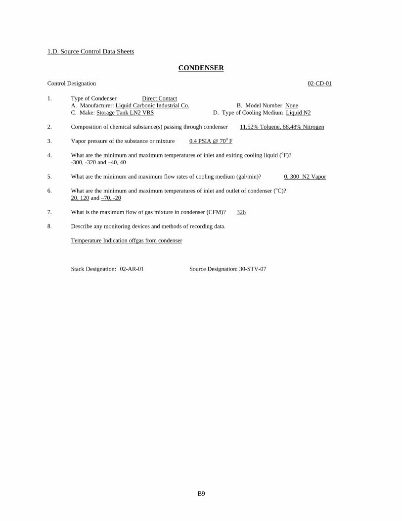
1.D. Source Control Data Sheets
CONDENSER
Control Designation 02-CD-01
1. Type of Condenser Direct ContactA. Manufacturer: Liquid Carbonic Industrial Co. B. Model Number NoneC. Make: Storage Tank LN2 VRS D. Type of Cooling Medium Liquid N2
2. Composition of chemical substance(s) passing through condenser 11.52% Toluene, 88.48% Nitrogen
3. Vapor pressure of the substance or mixture 0.4 PSIA @ 70O F
4. What are the minimum and maximum temperatures of inlet and exiting cooling liquid (oF)?-300, -320 and –40, 40
5. What are the minimum and maximum flow rates of cooling medium (gal/min)? 0, 300 N2 Vapor
6. What are the minimum and maximum temperatures of inlet and outlet of condenser (oC)?20, 120 and –70, -20
7. What is the maximum flow of gas mixture in condenser (CFM)? 326
8. Describe any monitoring devices and methods of recording data.
Temperature Indication offgas from condenser
Stack Designation: 02-AR-01 Source Designation: 30-STV-07

B10
SCRUBBER
Control Designation: 02-CD-04
1. Type of Scrubber (venturi, packed tower, etc.): VenturiA. Make: 8” Haveg 7014 B. Model No.C. Manufacturer: Schutte & Koerting
2. Is the scrubber used for particulate control or gas absorption? Gas AbsorptionA. If used for particulate control attach a particle size distribution analysis.B. If used for gas absorption; list all gases being absorbed by their chemical name. HCl, Cl2, Toluene
3. What is the liquid being used for absorption? Water
4. What are the chemical additives in the liquid? Give chemical names and their concentrations. How are theymaintained? No Additives
5. What are the minimum and maximum values for pH? NA/NA
6. What are the minimum and maximum values for oxidation-reduction potential (mV)? NA/NA
7. Is the liquid once through or recirculated? Once-through
8. Is the scrubber equipped with a mist eliminator? Yes No XXX If yes what is the type and the dimension?
9. What are the minimum and maximum flow rates of the liquid (gal/min)? 9 (min), 22 (max)What type of monitor and recorder? Rotometer
10. What are the minimum and maximum flow rates of the gas (ft3/sec)? 0 (Min), 2 (Max)What type of monitor and recorder? None
11. What is the minimum and maximum pressure drops across the scrubber(psi)? 0, 1What type of monitor and recorder? None
12. Relative direction of gas and liquid flow (co-current or counter- current)? Co-current
13. Venturi Scrubber*A. Length and diameter of throat? 44”, 4.75”B. Mechanism of introduction of the liquids (nozzles, pipes, etc.)? Nozzle Type of nozzle(s)? SprayC. Inlet gas temperature (ºF)? 104 F (Max) Outlet (ºF)? 104 F (Max)D. Inlet and Outlet particle grain loading (grains/dscf)? NA
14. Packer Tower*A. Number of transfer units?B. Height of transfer units?C. Type and size of packing material?D. Height of packed section (ft.)?E. Total height of tower (ft.)? Diameter (ft)?
15. Sketch of Scrubber. On file
16. Does the scrubber have a fan? No
Stack Designation: 02-AR-05 Source Designation: 02-PRV-01e
Modified 11/23/99, 3/19/01

B11
SCRUBBERControl Designation: 02-CD-05
1. Type of Scrubber (venturi, packed tower, etc.): Venturi followed by packed towerA. Make: Custom Design B. Model No. WKH-1.8 Ejector, M-08 Packed TowerC. Manufacturer: Anderson 2000 Inc.
2. Is the scrubber used for particulate control or gas absorption? Gas AbsorptionA. If used for particulate control attach a particle size distribution analysis.B. If used for gas absorption; list all gases being absorbed by their chemical name. Chlorine, HCl
3. What is the liquid being used for absorption? Water (sodium hydroxide solution feed to maintain pH)
4. What are the chemical additives in the liquid? Give chemical names and their concentrations. How are theymaintained? NaOH feed to maintain concentration typically over 15%.
5. What are the minimum and maximum values for pH? 6.5(Min), 14(Max)
6. What are the minimum and maximum values for oxidation-reduction potential (mV)? NA, NA
7. Is the liquid once through or recirculated? Recirculated
8. Is the scrubber equipped with a mist eliminator? Yes XXX No If yes, what is the type and the dimension?6” Kynar Mist Eliminator
9. What are the minimum and maximum flow rates of the liquid (gal/min)? at venturi: 100(min), 200 (max)at packed tower: 10 (min), 100 (max)
What type of monitor and recorder? Magmeter, Process Computer Data Historian
10. What are the minimum and maximum flow rates of the gas (ft3/sec)? 3 (Min), 30 (Max)What type of monitor and recorder? None
11. What is the minimum and maximum pressure drops across the scrubber?0.0722 design, 4.5” alarm 1 in. WC (Min), 10 in WC (Max)
What type of monitor and recorder? Pressure Gage and Computer Memory
12. Relative direction of gas and liquid flow (co-current or counter- current)? Venturi: Co-currentPacked Tower Countercurrent
13. Venturi Scrubber*A. Length and diameter of throat? See sketch in fileB. Mechanism of introduction of the liquids (nozzles, pipes, etc.)? Nozzle Type of nozzle(s)? SprayC. Inlet gas temperature (ºF)? 150 F (Max) Outlet (ºF)? 120 F (Max)D. Inlet and Outlet particle grain loading (grains/dscf)? NA
14. Packer Tower*A. Number of transfer units? 10B. Height of transfer units? 11 inchesC. Type and size of packing material? 1” PVC saddle packingD. Height of packed section (ft.)? 10E. Total height of tower (ft.)? 11’8” Diameter (ft)? 30” inside diameter
15. Sketch of Scrubber. On File
16. Does the scrubber have a fan? No
Stack Designation: 02-AR-05 Source Designation: 02-PRV-01d, 02-PRV-01e
Modified 11/23/99

B12
SCRUBBER
Control Designation: 02-CD-06
1. Type of Scrubber (venturi, packed tower, etc.): VenturiA. Make: 6” Haveg 7014 B. Model No.C. Manufacturer: Schutte & Koerting
2. Is the scrubber used for particulate control or gas absorption? Gas AbsorptionA. If used for particulate control attach a particle size distribution analysis.B. If used for gas absorption; list all gases being absorbed by their chemical name. HCl, VOCs
3. What is the liquid being used for absorption? Water
4. What are the chemical additives in the liquid? Give chemical names and their concentrations. How are theymaintained?
5. What are the minimum and maximum values for pH? 1 (Min), 8 (Max)
6. What are the minimum and maximum values for oxidation-reduction potential (mV)? NA/NA
7. Is the liquid once through or recirculated? Once-through
8. Is the scrubber equipped with a mist eliminator? Yes No XXX If yes what is the type and the dimension?
9. What are the minimum and maximum flow rates of the liquid (gal/min)? 5 (min), 24 (max)What type of monitor and recorder? Magnetic meter, computer memory
10. What are the minimum and maximum flow rates of the gas (ft3/sec)? 0 (Min), 5 (Max)What type of monitor and recorder? None
11. What is the minimum and maximum pressure drops across the scrubber(psi)? 0 (min), 1 (max)What type of monitor and recorder? None
12. Relative direction of gas and liquid flow (co-current or counter- current)? Co-current
13. Venturi Scrubber*A. Length and diameter of throat? 30”, 3.5”B. Mechanism of introduction of the liquids (nozzles, pipes, etc.)? Nozzle Type of nozzle(s)? SprayC. Inlet gas temperature (ºF)? 104 F (Max) Outlet (ºF)? 104 F (Max)D. Inlet and Outlet particle grain loading (grains/dscf)? NA
14. Packer Tower*A. Number of transfer units?B. Height of transfer units?C. Type and size of packing material?D. Height of packed section (ft.)?E. Total height of tower (ft.)? Diameter (ft)?
15. Sketch of Scrubber. On file
16. Does the scrubber have a fan? No
Stack Designation: 02-AR-05 Source Designation: 02-PRV-01d

B13
SCRUBBER
Control Designation: 02-CD-08
1. Type of Scrubber (venturi, packed tower, etc.): Packed towerA. Make: B. Model No. “VCP Special” Counter-Current with Mist EliminatorC. Manufacturer: Ceilcote Company
2. Is the scrubber used for particulate control or gas absorption? Gas AbsorptionA. If used for particulate control attach a particle size distribution analysis.B. If used for gas absorption; list all gases being absorbed by their chemical name. HCl & BzCl
3. What is the liquid being used for absorption? Water
4. What are the chemical additives in the liquid? Give chemical names and theirconcentrations. How are they maintained?
5. What are the minimum and maximum values for pH? 1.0 , NA
6. What are the minimum and maximum values for oxidation-reduction potential (mV)? NA/NA
7. Is the liquid once through or recirculated? Recirculated
8. Is the scrubber equipped with a mist eliminator? Yes XXX No If yes, what is the type and the dimension?6” Polypropylene Mesh Pad
9. What are the minimum and maximum flow rates of the liquid (gal/min)? 16 (min), 56 (max) thru Packed TowerWhat type of monitor and recorder? None 1 (min) for makeup
10. What are the minimum and maximum flow rates of the gas (ft3/sec)? 0 (Min), 12.5 (Max)What type of monitor and recorder? None
11. What is the minimum and maximum pressure drops across the scrubber? 1, 10 in WCWhat type of monitor and recorder? None
12. Relative direction of gas and liquid flow (co-current or counter- current)? Countercurrent
13. Venturi Scrubber*A. Length and diameter of throat?B. Mechanism of introduction of the liquids (nozzles, pipes, etc.)? Nozzle Type of nozzle(s)?C. Inlet gas temperature (ºF)? Outlet (ºF)?D. Inlet and Outlet particle grain loading (grains/dscf)?E.
14. Packer Tower*A. Number of transfer units? 8B. Height of transfer units? 11 inchesC. Type and size of packing material? 1” Polypropylene TellerettesD. Height of packed section (ft.)? 8E. Total height of tower (ft.)? 26 Diameter (ft)? 2
15. Sketch of Scrubber. On file
16. Does the scrubber have a fan? Yes
Stack Designation: 02-AR-18 Source Designation: 02-TTE-04, 02-TTE-05, 05-TTE-0105-TTE-02

B14
SCRUBBER
Control Designation: 05-CD-09
1. Type of Scrubber (venturi, packed tower, etc.): VenturiA. Make: Ejector Venturi B. Model No. Type 7014 3” Standard scrubber-separator systemC. Manufacturer: Schutte & Koerting
2. Is the scrubber used for particulate control or gas absorption? Gas AbsorptionA. If used for particulate control attach a particle size distribution analysis.B. If used for gas absorption; list all gases being absorbed by their chemical name. HCl, air
3. What is the liquid being used for absorption? Water
4. What are the chemical additives in the liquid? Give chemical names and their concentrations. How are theymaintained? N/A
5. What are the minimum and maximum values for pH? 1 (Min), 8 (Max)
6. What are the minimum and maximum values for oxidation-reduction potential (mV)? NA/NA
7. Is the liquid once through or recirculated? Once-through
8. Is the scrubber equipped with a mist eliminator? Yes If yes what is the type and the dimension?Schutte & Koerting separator. The dimensions are 5” x 12” x 10” high.
9. What is the minimum flow rate of the liquid (gal/min)? 1 (min) What type of monitor and recorder? Local flow meter
10. What are the minimum and maximum flow rates of the gas (ft3/sec)? 0 (Min), 5 (Max)What type of monitor and recorder? None
11. What is the minimum and maximum pressure drops across the scrubber(psi)? 0 (min), 1 (max)What type of monitor and recorder? None
12. Relative direction of gas and liquid flow (co-current or counter- current)? Co-current
13. Venturi Scrubber*Length and diameter of throat? 0.5”Mechanism of introduction of the liquids (nozzles, pipes, etc.)? Nozzle Type of nozzle(s)? SprayC. Inlet gas temperature (ºF)? 115 F (Max) Outlet (ºF)? 115 F (Max)D. Inlet and Outlet particle grain loading (grains/dscf)? NA
14. Packer Tower*A. Number of transfer units?B. Height of transfer units?C. Type and size of packing material?D. Height of packed section (ft.)?E. Total height of tower (ft.)? Diameter (ft)?
15. Sketch of Scrubber. On file
Does the scrubber have a fan? No
What is the minimum pressure of the water to the scrubber? 1 psig
Stack Designation: 02-AR-13 Source Designation: 05-STV-01,01a,01b, 05-STV-03,04,05
Added 11/23/99, Modified 02/18/00

B15
1.E. Process Stack Sheet Information
N e w D is t a n c e t o G a s D is cha rge
# o f J e rsey P r e v i o u s N e a r e s t D iameter Exit D is cha rge D irectio n
S t a c k S ig S t a c k C erti f icate P roper ty D im e n s i o n D is cha rge T e m p R ate (Up,D o w n ,
D e s ignat ion D e s c riptio n S o u r c e s # N u m b e r s Line (ft) (in) H e ight (ft) (F ) ( ac fm) H o rizonta l )
02-A R -01 T o luene S to r a g e T a n k 1 65 30208 500 2 30-40 < 40 < 326 D o w n
02-A R -03 T o l u e n e R e c y c l e T a n k 1 145 085837 1200 2 8 55 5 D o w n
02-A R -05 C lo rinato r N o . 1 112 8 142 082699 1500 10 28.5 120 1800 Up
00531
000121
02-A R -06 S o u t h C o l u m n S t e a m J e t 1 125 G R A N 1200 4 60 212 0.95 H o rizonta l
02-A R -07 N o rth C o l u m n S t e a m J e t 1 63 C T 8 3 8 1 1200 4 60 212 0.95 (max) H o rizonta l
02-A R -08 Benza l R e s i due Tank 1 139 78901 1140 3 0 100 0.15 D o w n
02-A R -09 W e s t B z C l S to r a g e T a n k 1 103 061769 1200 3 20 70 98 H o rizonta l
02-A R -10 E a s t B z C l S to r a g e T a n k 1 104 C T -61770 1200 3 20 70 3.09 H o rizonta l
02-A R -12 N o rth B zC l Sto r a g e T a n k 1 64 8382 1300 3 19 <100 26.6(max) D o w n
05-A R -18 H C l/B zC l Load&Scrub C T 4 S 4 4 81 019245 1400 10 27 <100 793 Up
02-A R -20 B zC l,B zP h, B zC H O D rumming 1 G R A N 1300 4 20 A mbient 7(max) D o w n
02-A R -21 B e n z a l d e h y d e S t o r a g e T k 1 162 119449 1200 3 1 <120 <0.3 D o w n
05-A R -22 C o m bined H C l S t o r a g e T a n k s 6 N /A N /A 1200 1.5 56 60 4.02 (max) Up
1.F. Raw Material/Contaminant List
VOCsHAPs
Benzotrichloride 98-07-7Benzyl Chloride 100-44-7o, m, p xylenes 13300207Propylene oxide 75-56-9Toluene 108-88-3Xylene (m) 108383Xylene (o) 95476Xylene (p) 106423Chlorine 7782-50-5Hydrochloric Acid 7647-01-0Benzene 71-43-2
OtherChlorodifluoromethane 75-46-6
Modified 11/23/99, 02/18/00

B16
2.A., B., and C. Technical Information - Release and Alteration/Amendment Limits
Category: Volatile Organic Compounds OTHER
Sub-Category: HAPS OTHERS HAPS
Constituent: Toluene Benzy l Ch lo r i de B e n z e n e P ropy l ene Ox i de HCl Cl2SignificantSources Lb/H r Lb/H r Lb/H r Lb/H r Lb/H r Lb/H r Lb/H r
02-PRV-01d 0.684 0.05 0.02 0.1 0.1 0.1
02-PRV-01e 2.736 0.2 0.08 0.4 0.4 0.4
02-PRV-05 0.2 0.79 0.1 0.1 0.1
02-PRV-06 0.2 0.79 0.1 0.1 0.1
02-PTV-02 No pound/hour, Storage Only
02-PTV-05 No pound/hour, Storage Only
02-STV-02 No pound/hour, Storage Only
02-STV-03 No pound/hour, Storage Only
02-STV-05 No pound/hour, Storage Only
02-STV-08 No pound/hour, Storage Only
02-TTE-01 0.29 0.52
02-TTE-04 0.04
02-TTE-05 0.07
05-STV-01 No pound/hour, Storage Only
05-STV-01a No pound/hour, Storage Only
05-STV-01b No pound/hour, Storage Only
05-STV-03 No pound/hour, Storage Only
05-STV-04 No pound/hour, Storage Only
05-STV-05 No pound/hour, Storage Only
05-TTE-01 0.54
05-TTE-02 0.27
30-STV-07 No pound/hour, Storage Only
Category: Volatile Organic Compounds OTHER
Sub-Category: HAPS OTHERS HAPS
Constituent: Toluene Benzy l Ch lo r i de B e n z e n e P ropy l ene Ox i de HCl Cl2Ton/Year Significant 2.521 9.131 0.7 0.15 4.9055 6.876 3.066
Ton/Year Insignificant 0.19 0.04 0 0 0 0 0
Ton/Year Fugitive 5 1 0 0.5 1.05 0.5 0.2
Lb/Product 1.70E-04 4.20E-05 8.60E-06 8.70E-06 3.70E-06 2.60E-06 6.00E-07
Modified 02/18/00

B17
3. Compliance Plan
3.A. Applicable Requirements
The following storage and transfer VOC emission sources are regulated under and subject to the terms andconditions of N.J.A.C. 7:27-8.2(a), 8.3(a through e, h, i and j), 8.4, 8.9, 16.2, 16.4
Significant Sources Insignificant Sources30-STV-07 Toluene Storage Tank 02-STV-09 Triphenylphosphine Storage Tank02-PTV-02 Toluene Recycle Tank
In addition, storage tank 30-STV-07 is regulated under and subjectto the terms and conditions of 40 CFR 63.123.
The following process VOC emission sources are regulated under and subject to the terms and conditions ofN.J.A.C. 7:27-8.2(a), 8.3(a through e, h, i and j), 8.4, 8.9, 16.16[b, c, d, g(1,4)], 16.22, 40 CFR 63.117(b), 40 CFR63.118(c and h)
Significant Sources02-PRV-01e Toluene Decanter02-PRV-01d Toluene Stripper02-PRV-05 Benzyl Refining Column02-PRV-06 Benzyl Refining Column
The following emission sources are regulated under and subject to the terms and conditions of N.J.A.C. 7:27-8.2(a), 8.3(a through e, h, i and j), 8.4, 8.9
Significant Sources02-PTV-05 Benzal Chloride Residue Tank02-STV-05 BzCl Storage Tank02-STV-02 BzCl Storage Tank02-STV-03 BzCl Storage Tank02-STV-08 Benzaldehyde Storage Tank05-STV-01 HCl Storage Tank05-STV-01a HCl Storage Tank05-STV-01b HCl Storage Tank05-STV-03 HCl Storage Tank05-STV-04 HCl Storage Tank05-STV-05 HCl Storage Tank05-TTE-01 Loading Dock05-TTE-02 Loading Dock02-TTE-04 Loading Dock02-TTE-05 Loading Dock02-TTE-01 BzCl, BzPh, BzCHO Drumming
In addition, storage tanks 02-STV-02, 02-STV-03, 02-STV-05, and 02-PTV-05 and loading docks 02-TTE-01, 02-TT-02 are all regulated under and subject to the terms and conditions of 40 CFR 63.123.
The following emission sources are regulated under and subject to the terms and conditions of 40 CFR 63.123
Insignificant Sources02-STV-04 BzCl Storage Tank02-PTV-03 BzCl Shed Drumming Tank
No additional requirements beyond those referenced in the general section of the permit apply to these sources:
Modified 02/18/00

B18

B19
Insignificant Sources02-STV-01 Fire Foam Tank
All sources and all associated equipment in this process are regulated pursuant 40 CFR 63 Subparts A, F, G & H.
3.B. Recordkeeping, Monitoring, and Reporting
1. Recordkeeping
The permittee shall record the following information at the process level:a. The date of operationb. Amount of fresh chlorine fed to the reactor system per day
The permittee shall record pressure drops, pH, and flow rates as per 2.a. below. The permittee shall alsorecord calibration dates as per 2.b. below.
The permittee shall record on a monthly basis and running yearly total the throughput of each tank andtransfer operation to comply with the limits with 3.C.1. below.
The permittee shall have readily available the startup, shutdown, malfunction plan as required pursuant to40 CFR 63.6(e)(3).
Effective April 22, 1999, the permittee shall prepare and have readily available a “MaintenanceWastewater Plan” pursuant to 40 CFR 63.105.
Additional recordkeeping requirements pursuant to 40 CFR 63.152 and 40 CFR 63.181 shall also bemaintained and readily available.
The permittee shall have readily available the documentation required to determine wastewaterapplicability pursuant to 40 CFR 63.144 and 40 CFR 63.147(f). The permittee has determined that allwastewater streams are Group 2 wastewater streams and therefore only those citations applicable to Group2 streams shall apply.
These records shall be maintained on site for a minimum of five years after the last collection, in a permanently boundlogbook or readily accessible files, readily accessible computer memory, or by anothermethod acceptable to the Regional Enforcement Office. These records must also beavailable to representatives of the Department.
2. Monitoring
a. The following control devices shall be maintained and operatedin accordance with the specifications defined in Section 1D ofthis process package. A double asterisk in the following textdenotes that the monitoring equipment is not yet in place.Monitoring and recordkeeping requirements shall not berequired for those parameters until a monitoring device is inplace. Upon completion of installation of the monitoringdevice, monitoring and recordkeeping shall be required.
02-CD-01Condenser for Toluene Storage/Unloading (30-STV-07)The outlet temperature of the condenser shall be
monitored and recorded at least once per

B20
operating day. The temperature shall bemaintained below –20 degrees Centigrade.
02-CD-04 Scrubber for HCl Absorber, Reactor System, and Toluene Decanter (02-PRV-01e)
Modified 06/01/99, 6/ 17/99, 11/23/99

B21
The flow rate of the water at the inlet shall be monitored and recorded at leastonce per day. The flow rate shall be maintained above 9 gallons per minute. Inthe event that the flow meter cannot be read, a back-up reading for inlet waterpressure shall be monitored and recorded at least once per day. The pressureshall be maintained above 0.5 psig.
02-CD-05** South Caustic Scrubber following 02-CD-04 and 02-CD-06 (02-PRV-01d, 02-PRV-01e)Venturi – The flow rate of the water at the inlet
shall be monitored and recorded at leastonce per day. The flow rate shall bemaintained above 100 gallons per minute.In the event that the flow meter cannot beread, a back-up reading for inlet waterpressure (circulation pump) shall bemonitored and recorded at least once perday. The pressure shall be maintainedbetween 50 - 130 psig.
Packed Tower - The flow rate of the water at theinlet and the pressure drop across thescrubber shall be monitored and recordedat least once per day. The flow rate shallbe maintained between 10 and 100 gallonsper minute. The pressure drop shall bemaintained between 0.005 and 10 inches ofwater column. In the event that the flowmeter cannot be read, a back-up readingfor inlet water pressure (circulationpump) shall be monitored and recorded atleast once per day. The pressure shall bemaintained between 50 - 130 psig.
Make-up NaOH – A grab sample of the scrubbing mediumshall be taken, analyzed, and recorded atleast once per day. The causticconcentration of the scrubbing mediumshall be maintained above 1%.
** A differential pressure meter to measure pressure drop acrossthe packed tower shall be installed and operational within 180days of the effective date of this permit.
02-CD-06Scrubber for Toluene Stripper (02-PRV-01d)The flow rate of the water at the inlet shall be
monitored and recorded at least once per day.The flow rate shall be maintained above 5gallons per minute. In the event that theflow meter cannot be read, a back-up readingfor inlet water pressure shall be monitoredand recorded at least once per day. Thepressure shall be maintained above 1 psig.

B22
02-CD-08** Scrubber for Loading Docks (02-TTE-04, 05, 05-TTE-01, 02)
The pressure of the supply pump to the inlet ofthe scrubber, the flow rate of the makeupwater, and the pressure drop across thescrubber shall be monitored and recorded atleast once per day if the loading docks are inuse during that operating day. The pressure ofthe supply pump to the inlet of the scrubbershall be maintained between 10 and 50 psig.The flow rate of the makeup water shall bemaintained at a minimum of 1 gallon perminute. The pressure drop across the scrubbershall be maintained between 0.005 and 10inches of water column. In the event that theflow meter for the make-up water cannot beread, a back-up reading for make-up waterpressure shall be monitored and recorded atleast once per day. The pressure shall bemaintained between 1 and 50 psig.
** A pressure meter to measure pressure drop across the scrubber,a pressure meter to measure the pressure of the water supplyto the scrubber inlet, and a flow meter to measure makeupwater shall be installed and operational within 180 days ofthe effective date of this permit.
Modified 06/01/99, 11/23/99, 03/17/00, 03/19/01

B23
05-CD-09Scrubber for HCl Storage Tanks (05-STV-01,01a,01b, 05-STV-03,04,05)
The flow rate of the water to the scrubber shallbe monitored and recorded at least once perday. The flow rate of the water to thescrubber shall be maintained at a minimum of 1gallon per minute. In the event that the flowmeter for the water to the scrubber cannot beread, a back-up reading for water pressureshall be monitored and recorded at least onceper day. The pressure shall be maintainedbetween 1 and 50 psig.
b. The permittee shall maintain and calibrate all monitorsconsistent with the manufacturers specifications or otherwritten procedures. All specifications must be made availableto a representative of the Department upon request.
c. Leak detection and repair shall be performed pursuant to 40CFR 63 Subpart H. Specifically the following requirementsfor the following equipment types shall be performed:
40 CFR 63.163 Pumps in light liquid service40 CFR 63.166 Sampling connection systems40 CFR 63.167 Open-ended valves or lines
40 CFR 63.168 Valves in gas/vapor service and in lightliquid service
40 CFR 63.169 Pumps, valves, connectors, and agitatorsin heavy liquid service; instrumentationsystems; and pressure relief devices in liquidservice
40 CFR 63.174 Connectors in gas/vapor service and in lightliquid service
d. A maximum of 248,800 pounds of chlorine shall be fed to the reactor system in any one day.
3. Reporting
Release Summary Reports: The permittee shall submit to the Department, beginning from the effective date of this permit,a summary of all releases from this process. The requirements of this report aredefined in Section III.D.3.a. of this permit.
The permittee shall submit to the Department and the USEPA, RegionII on a semi-annual basis periodic reports pursuant to 40 CFR63.152. The submittals shall be received no later than May 18and November 19 of each year.
The permittee shall submit to the Department and the USEPA, Region II on a semi-annual basis periodic reports pursuantto 40 CFR 63.182. The submittals shall be received no later than January 21 and July21 of each year.
By September 20, 1999, the permittee shall submit to the Department and the USEPA, Region II a Notification ofCompliance Status for wastewater streams pursuant to 40 CFR 63.146.
3.C. Special Conditions

B24
1. Storage tank 30-STV-07, toluene storage tank, shall be limited to a maximum throughput of 85,300,000pounds per calendar year of toluene. Storage tank 02-PTV-02, toluene recycle tank, shall be limited to a maximum throughput of 256,000,000pounds per calendar year of toluene. Storage tank 02-PTV-05, benzal chloride residue tank, shall be limited to a maximum throughput of15,000,000 pounds per calendar year of benzal chloride residue. Storage tank 02-STV-05, north benzyl chloride storage tank, shall be limited to a maximum throughput of60,000,000 pounds per calendar year of benzyl chloride. Storage tanks 02-STV-02, 03, west & east benzyl chloride storage tanks, shall be limited to a maximum totalthroughput of 110,000,000 pounds per calendar year of benzyl chloride. Modified 06/17/99, 02/18/00
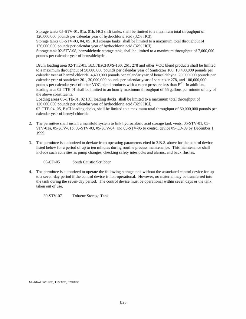
B25
Storage tanks 05-STV-01, 01a, 01b, HCl shift tanks, shall be limited to a maximum total throughput of126,000,000 pounds per calendar year of hydrochloric acid (32% HCl). Storage tanks 05-STV-03, 04, 05 HCl storage tanks, shall be limited to a maximum total throughput of126,000,000 pounds per calendar year of hydrochloric acid (32% HCl). Storage tank 02-STV-08, benzaldehyde storage tank, shall be limited to a maximum throughput of 7,000,000pounds per calendar year of benzaldehyde. Drum loading area 02-TTE-01, BzCl/BzCHO/S-160, 261, 278 and other VOC blend products shall be limitedto a maximum throughput of 50,000,000 pounds per calendar year of Santicizer 160, 18,400,000 pounds percalendar year of benzyl chloride, 4,400,000 pounds per calendar year of benzaldehyde, 20,000,000 pounds percalendar year of santicizer 261, 30,000,000 pounds per calendar year of santicizer 278, and 100,000,000pounds per calendar year of other VOC blend products with a vapor pressure less than E-2. In addition,loading area 02-TTE-01 shall be limited to an hourly maximum throughput of 55 gallons per minute of any ofthe above constituents. Loading areas 05-TTE-01, 02 HCl loading docks, shall be limited to a maximum total throughput of126,000,000 pounds per calendar year of hydrochloric acid (32% HCl).02-TTE-04, 05, BzCl loading docks, shall be limited to a maximum total throughput of 60,000,000 pounds percalendar year of benzyl chloride.
2. The permittee shall install a manifold system to link hydrochloric acid storage tank vents, 05-STV-01, 05-STV-01a, 05-STV-01b, 05-STV-03, 05-STV-04, and 05-STV-05 to control device 05-CD-09 by December 1,1999.
3. The permittee is authorized to deviate from operating parameters cited in 3.B.2. above for the control devicelisted below for a period of up to ten minutes during routine process maintenance. This maintenance shallinclude such activities as pump changes, checking safety interlocks and alarms, and back flushes.
05-CD-05 South Caustic Scrubber
4. The permittee is authorized to operate the following storage tank without the associated control device for upto a seven-day period if the control device is non-operational. However, no material may be transferred intothe tank during the seven-day period. The control device must be operational within seven days or the tanktaken out of use.
30-STV-07 Toluene Storage Tank
Modified 06/01/99, 11/23/99, 02/18/00

B1
1. A. General Process Description
Tetrathal Manufacturing Process
Tetrachlorophthalic anhydride (TCPA or Tetrathal) is produced by reacting chlorine with phthalic anhydride in thepresence of molybdenum pentachloride catalyst in three reactors in series.
The offgas chlorine is scrubbed out and sent to the wastewater treatment plant
The molten TCPA is then degassed, flaked, cooled and packaged.
1.B. Process Flow Diagrams
Step Controls Stacks
TCPA Process Flow Diagram
See Step 1 Process Flow
Raw MaterialStorage
ReactorSystem
ProductPackaging
04-AR-1 thru 6
04-AR-7 thru 9
04-AR-10 thru 12
See Step 2 Process Flow
See Step 3 Process Flow

B2
Equipment Controls Stacks
Raw Material Storage StepTCPA - Step 1
Sodium Thiosulfate
Storage
Therminol 59Storage Tank(2)
Plant DistributionChlorine(TC) - Covered in BzCl Process Phthalic Anhydride(TC) - Covered in Benzyl Phthalate ProcessNaOH(50% Caustic) - Covered in Benzyl Phthalate Process
Therminol 66 Storage Tank(2)
None 04-AR-01
ConservationVent
ConservationVent
ConservationVent
04-AR-02
04-AR-03,04
04-AR-05,06
Phthalic Anhydride
Storage System
Modified 02/18/00

B3
Equipment Controls Stacks
TCPA - Step 2Reactor Step
ReactorSystem
FlakerFeed Tank
Dechlorination Reactors(2)
Scrubber04-CD-01
04-AR-08
TherminolHeater
None 04-AR-09
CatalystFeed Box
None 04-AR-07
04-WW-01,02
To Step 3

B4
Equipment Controls Stacks
TCPA - Step 3Packaging Step
Flaker
04-AR-10Conveyer/Elevator
Bagger
Baghouse Filter04-CD-02
CoolingTower
None 04-AR-11
04-SW-02
04-SW-01
Warehouse Pallet Loading Bay
None 04-AR-12
FlakeHopper
Flaker Rework Hopper
04-SW-02
From Step 2
TCPA Product

B5
1.C. Equipment, Control Device, and Source Sheet Information
Tetrathal (TCPA) Manufacturing Equipment and Control Device List - Step 1
Raw Material Storage
The Raw Material Storage step of the Tetrathal Manufacturing system consists of one phthalic anhydride storageand batch tank, one sodium thiosulfate storage tank, two Therminol 59 storage tanks and two Therminol 66storage tanks. The phthalic anhydride is unloaded from railroad tank cars. The sodium thiosulfate is unloadedfrom trailers. The mobiltherm and the therminol are heat transfer oils and are supplied infrequently from drums.Chlorine, sodium hydroxide and some phthalic anhydride are supplied to this process by plant distribution. Thechlorine storage is incorporated into the Benzyl Chloride Process and the sodium hydroxide and additionalphthalic anhydride are incorporated into the Benzyl Phthalate Process.
Equipment Capacity ControlPhthalic anhydride storage system (1 source) 10,000 gallons None(04-STV-01 + 04-STV-07)
Insignificant Sources Capacity Control InsignificanceSodium thiosulfate storage tank 9,500 gallons Conservation Vent <10K Storage(04-STV-04)Therminol 59 (H) storage tank 1,000 gallons Conservation Vent <10K Storage(04-STV-02)Therminol 59 (C) storage tank 1,000 gallons Conservation Vent <10K Storage(04-STV-03)Therminol 66 (H) storage tank 1,000 gallons Conservation Vent <10K Storage(04-STV-05)Therminol 66(C) storage tank 1,000 gallons Conservation Vent <10K Storage(04-STV-06)
Tetrathal (TCPA) Manufacturing Equipment and Control Device List - Step 2
Reactor System
The Reactor System of the Tetrathal Manufacturing Process consists of one catalyst feed box, one cascaded reactorsystem(3 tanks), a flaker feed tank, a dechlorination system, a process heater and an emergency scrubber. Phthalicanhydride, chlorine, molybdenum pentachloride catalyst and nitrogen as a purge are fed to the reactor. The offgasflows to the dechlorination system, which in turn feeds to the emergency scrubber. Tetrathal from the reactors ispumped to the flaker feed tank, which also vents to the emergency scrubber. The gas fired therminol heater heatstherminol, which is used to heat process equipment. The therminol heater vents to the atmosphere. Molybdenumpentachloride is added manually to the reactor system through the catalyst feed (glove) box.
Equipment Capacity ControlDechlorination Thiosulfate Reactor 1,000 gallons Scrubber(04-PRV-03d)Dechlorination Cl2 Reactor 3,000 gallons Scrubber(04-PRV-03e)Therminol Heater 3MBTU/Hr Max Rate None(04-PRV-01)
Insignificant Sources Capacity Control InsignificanceCatalyst Feed Box 25 gallons/batch Conservation Vent <50 lb/hr Throughput(04-PRV-05)
Exempt Sources Capacity Exempt StatusReactor System (3 Tanks) (1 source) 2,500 gallons each No Direct Emissions

B6
(04-PRV-03a, 04-PTV-03b, 04-PRV-03c)Flaker Feed Tank 2,100 gallons No Direct Emissions(04-PTV-01)
Modified 02/18/00, 5/8/00

B7
Tetrathal (TCPA) Manufacturing Equipment and Control Device List - Step 3
Product Packaging Step
The Product Packaging step to the Tetrathal Manufacturing System consists of a flaker, a cooler conveyer, a bucketelevator, a flake hopper, a bagger operation, a flaker recovery system, a cooling tower, a baghouse filter, and truckloading areas. The molten TCPA is converted to flakes in the flaker. The flakes are then cooled in the coolingconveyer and lifted to the bagging operation in the elevator. All of the equipment from the flaker to the flakerrecovery system is vented to the baghouse filter. The cooling tower supplies cooling water to only the coolingconveyer.
Equipment Capacity ControlFlaker 6,000 lbs/Hr Baghouse Filter(04-PRV-02e)Cooling Conveyer 6,000 Lbs/Hr Baghouse Filter(04-PRV-02)Bucket Elevator 6,000 Lbs/Hr Baghouse Filter(04-PRV-02c)Bagger 6,000 Lbs/Hr Baghouse Filter(04-PRV-02b)Flake Hopper 4,560 gallons Baghouse Filter(04-PRV-02a)Flaker Rework Hopper 300 gallons Baghouse Filter(04-PRV-02d)
Insignificant Sources Capacity Control InsignificanceCooling Tower 750 gallons None <50 lb/hr additive(04-PCT-01)
Exempt Sources Capacity Exempt StatusWarehouse Pallet Loading Bay n/a No Direct/Indirect Emissions(04-TTE-01)

B8
1.D. Source Control Data Sheets CONTROL DATA SHEETSCRUBBERS
Control Designation: 04-CD-01
1. Type of Scrubber (venturi, packed tower, etc.): Venturi followed by Packed TowerA. Make: Custom DesignB. Manufacturer: Anderson
2. Is the scrubber used for particulate control or gas absorption? Gas AbsorptionA. If used for particulate control attach a particle size distribution analysis.B. If used for gas absorption; list all gases being absorbed by their chemical name. Chlorine
3. What is the liquid being used for absorption? >1% Caustic
4. What are the chemical additives in the liquid? Give chemical names and their concentrations. How are theymaintained? >15% NaOH Solution, manually sampled weekly, analyzed and maintained by blowing down, or adding caustic,or water, as needed to keep the concentration above 15% NaOH.
5. What are the minimum and maximum values for pH? 11 (Min), 14 (Max)
6. What are the minimum and maximum values for oxidation-reduction potential (mV)? NA, NA
7. Is the liquid once through or recirculated? Recirculated
8. Is the scrubber equipped with a mist eliminator? Yes XXX No If yes what is the type and the dimension?6” Kynar Mist Eliminator
Venturi Packed Tower9. What are the minimum and maximum flow rates of the liquid (gal/min)? 100 GPM 10 GPM
What type of monitor and recorder? Flow Meter to each step Minimums
10. What are the minimum and maximum flow rates of the gas (ft3/sec)? NA (Min),30 (Max)What type of monitor and recorder? None
Packed Tower11. What is the minimum and maximum pressure drops across the scrubber? 1 in. WC (Min), 20 in. WC (Max)
What type of monitor and recorder? Pressure Indicator
12. Relative direction of gas and liquid flow (co-current or counter- current)? Venturi - Co-currentPacked Tower - Counter current
13. Venturi Scrubber*A. Length and diameter of throat? 24”, 4”B. Mechanism of introduction of the liquids (nozzles, pipes, etc.)? Nozzle Type of nozzle(s)? Hollow ConeC. Inlet gas temperature (ºF)? 150 F (Max) Outlet (ºF)? 150 F (Max)D. Inlet and Outlet particle grain loading (grains/dscf)? NA, NA
14. Packer Tower*A. Number of transfer units? Not KnownB. Height of transfer units? Not KnownC. Type and size of packing material? 1” PVC Saddle PackingD. Height of packed section (ft.)? 10 FeetE. Total height of tower (ft.)? 15.3 Diameter (ft)? 2.5
15. Sketch of Scrubber. In application
16. Does the scrubber have a fan? No
* If Scrubber is not a venturi or packed tower, please answer any of the above questions pertaining to your design.*
Stack Designation: 04-AR-08 Source Designation: 04-PRV-03e, 04-PRV-03d

B9
CONTROL DATA SHEETDUST COLLECTOR
Control Designation: 04-CD-02
Manufacturer and Model: Micro Pulsaire
Specify: Baghouse
Number of Bags or Cartridge: 100 Size of Bags or Cartridge: 96 inches long
Total Bag or Cartridge Area: 1000 ft.2 Maximum Capacity (ACFM): 5,000
Bag Fabric: Filament Polyester with Fabric Weight: 16 oz/yd2
Teflon Membrane
Weave: 3 X 1 Twill Finish: Teflon Membrane
Efficiency (%): 99 Air to Cloth Ratio: 5,000 ACFM/1,000 ft2 = 5 ft/min max
Maximum Bag Temperature Capability (ºF): 300
Temperature of inlet (ºF): 275
Moisture Content of Inlet (%): Ambient
Is the Collector Insulated? No
Method of Bag Cleaning: Pulse Jet
Operating Pressure Drop (inches of water): Min 1.0, Max 15.0
What is the type of Monitor and Recorder? Field Mounted Pressure Gauge
Attach a Particle Size Distribution Analysis. n/a
Stack Designation: 04-AR-10 Source Designation: 04-PRV-02, 04-PRV-02a,04-PRV-02b, 04-PRV-02c04-PRV-02d, 04-PRV-02e
Modified 02/18/00

B10
Equipment Supplemental Form
1. Facility Description of Boiler: Therminol Heater (04-PRV-01)
2. Manufacturer: Eclipse Lookout Co. Make: Horizontal Liquid Tube HeaterModel: 200-4 MC-LT-MK-4 50L-Pro-TRI Nemm 4 Heater
3. Anticipated Date of Installation or Alteration: N/A
4. Boiler Type (Underline all that apply) Utility Boiler Non-utility Boiler Fire TubeWater Tube Package Field Erected
5. Maximum Gross Heat Input (MMBtu/hr): 3
6. Type Stream Output( lb/hr): N/A
7. Fuel to be Fired
Primary Fuel (Specify): Natural Gas Secondary Fuel (Specify):Maximum Annual Fuel Use: 25,764,702 CF Maximum Annual Fuel Use:Heating Value (Btu/lb Fuel): 1,020 Btu/CF Heating Value (Btu/lb Fuel):% Sulfur in Fuel: 0 % Sulfur in Fuel:
8. Air Pollution Control Technologies (Underline All That Apply)Low NOx Burners (LNB) Particulate Control – FiltrationStaged Air Combustion Electrostatic PrecipitatorScrubber Catalytic OxidizerSelective Non-Catalytic Reduction (SNCR) Other (Specify):Selective Catalytic Reduction (SCR)Flue Gas Recircualtion (FGR), Specify % FGR Induced Draft Forced Draft

B11
1.E. Process Stack Sheet InformationDistance to Discharge
# of New Previous Nearest Gas DirectionStack Sig Jersey Certificate Property Diameter Discharge Exit Discharge (Up,Down,
Designation Description Sources Stack # Numbers Line (ft) Dimension (in) Height (ft) Temp (F) Rate (acfm) Horizontal)
04-AR-01 PA Storage Tank 1 Gran 1500 4 15 <293 6.9(max) 0.2(avg) Horizontal04-AR-08 Reactor System 4 147 93527 1500 10 28.5 <150 <1800 Up04-AR-09 Therminol Heater 1 124 73725 1500 18 10 <600 <1500 Up04-AR-10 Cooler Conveyor(Baghouse) 4 Gran 1500 12 x 21 37 <300 <5000 Horizontal
1.F. Raw Material/Contaminant List
VOCsParticulateCONOxSOxHAPs
Hexachlorobenzene 118-74-1Phthalic Anhydride 85-44-9Chlorine 7782-50-5Hydrochloric Acid 7647-01-0
OtherNitrogen 7727-37-9Methane 74-82-8
2.A., B., and C. Technical Information - Release and Alteration/Amendment Limits
Category: Particulates VOCs OTHER CO NOx SO2Sub-Category: HAPS OTHERS HAPS OTHERS HAPS Other
Constiuent: Hexachlorobenzene P A P A Chlorine HCl MethaneSinificantSources Lb/H r Lb/H r Lb/H r Lb/H r Lb/H r Lb/H r Lb/H r Lb/H r Lb/H r Lb/H r Lb/H r
04-PRV-01 0.053 Below Threshold 0.012 0.093 0.441 0.00304-PRV-02 0.03 0.60 0.03 0.0804-PRV-02a 0.006 0.12 0.004 0.01504-PRV-02b 0.01 0.10 0.002 0.0104-PRV-02c 0.03 0.60 0.03 0.0804-PRV-02d 0.001 0.024 0.001 0.00304-PRV-02e 0.05 0.96 0.04 0.1204-PRV-03d 0.0204-PRV-03e Below Threshold04-STV-01 No pound/hour, Storage Only
Category: Particulates VOCs OTHER CO NOx SO2Sub-Category: HAPS OTHERS HAPS OTHERS HAPS Other
Constiuent: Hexachlorobenzene P A P A Chlorine HCl MethaneTon/Year Significant 0.16 0.40 3.23 0.40 0.10 0.24 0.60 0.05 0.41 1.93 0.01
Ton/Year Insignificant 0.00 0.00 0.00 0.00 0.38 0.00 0.04 0.00 0.00 0.00 0.00Ton/Year Fugitive 0.10 0.20 0.50 0.20 0.50 0.01 0.10 0.10 0.00 0.00 0.00
Lb/Product 4.51E-05 1.74E-04 N/A 1.74E-04 2.58E-04 6.87E-05 2.25E-04 N/A N/A N/A N/A

B12
3. Compliance Plan
3.A. Applicable Requirements
The following combustion source is regulated under and subject to the terms and conditions of N.J.A.C. 7:27-3.2(a, b, c), 3.6, 4.2(a), 8.2(a), 8.3(a through e, h, i, and j), 8.4, 8.9
Significant Sources04-PRV-01 Therminol Heater
The following particulate emission source types are regulated under and subject to the terms and conditions ofN.J.A.C. 7:27-6.2(a and d), 8.2(a), 8.3(a through e, h, i and j)
Significant Sources Insignificant Sources04-PRV-02 Cooling Conveyer 04-PRV-05 Catalyst feed box04-PRV-02a Flake Hopper04-PRV-02b Bagger04-PRV-02c Bucket Elevator04-PRV-02d Flake Rework Hopper04-PRV-02e Flaker
In addition, storage tank 04-STV-01 is regulated under and subject to the terms and conditions of 40 CFR 63.123.
The following emission sources are regulated under and subject to the terms and conditions of N.J.A.C. 7:27-8.2(a), 8.3(a through e, h, i and j), 8.4, 8.9
Significant Sources04-STV-01 Phthalic Anhydride Storage System04-PRV-03d Dechlorination Thiosulfate reactor04-PRV-03e Dechlorination Cl2 reactor
No additional requirements beyond those referenced in the general section of the permit apply to these sources:
Insignificant Sources04-STV-04 Sodium thiosulfate storage tank04-PCT-01 Cooling Tower04-STV-05 Therminol 66 (H) storage tank04-STV-05 Therminol 66 (C) storage tank04-STV-02 Therminol 59 (H) storage tank04-STV-03 Therminol 59 (C) storage tank
All sources and all associated equipment in this process are regulated pursuant 40 CFR 63 Subparts A, F, G & H.
3.B. Recordkeeping, Monitoring, and Reporting
1. Recordkeeping
The permittee shall record the following for particulate, VOC and Other emissions:a. The date of operationb. The number of batches and the time in hours of each batchc. Amount of phthalic anhydride fed to the reactor system per batch
The permittee shall record the following for the Therminol Heater( 04-PRV-01) on a yearly basis:

B13
a. The quantity of natural gas burned
The permittee shall record on a monthly basis and running yearly total the throughput of each tank andtransfer operation to comply with the limits with 3.C.1. below.
Modified 02/18/00

B14
The permittee shall record pressure drops, caustic concentrations, and flow rate as per 2.a. below. Thepermittee shall also record calibration dates as per 2.b. below.
The permittee shall have readily available the startup, shutdown, malfunction plan as required pursuant to40 CFR 63.6(e)(3).
Effective April 22, 1999, the permittee shall prepare and have readily available a “MaintenanceWastewater Plan” pursuant to 40 CFR 63.105.
Additional recordkeeping requirements pursuant to 40 CFR 63.152 and 40 CFR 63.181 shall also bemaintained and readily available.
The permittee shall have readily available the documentation required to determine wastewaterapplicability pursuant to 40 CFR 63.144 and 40 CFR 63.147(f). The permittee has determined that allwastewater streams are Group 2 wastewater streams and therefore only those citations applicable to Group2 streams shall apply.
These records shall be maintained on site for a minimum of five years after the last collection, in apermanently bound logbook or readily accessible files, readily accessible computer memory, orby another method acceptable to the Regional Enforcement Office. These records must also beavailable to representatives of the Department.
2. Monitoring
a. The following control devices shall be maintained and operated in accordance with the specificationsdefined in Section 1D of this process package.
04-CD-02 Baghouse Filter for Packaging Step (04-PRV-02, 2a, 2b, 2c, 2d,2e)The pressure drop shall be recorded at least once per batch during production while venting to the
baghouse. The pressure dropped shall be maintained between 1 and 15 inches of water.
04-CD-01 Scrubber for Dechlorination Reactors (04-PRV-03d, 3e)Venturi – The flow rate of the water at the inlet shall be monitored and recorded at least once
per day. The flow rate shall be maintained at or above 100 gallons perminute. In the event that the flow meter cannot be read, a back-up readingfor the inlet water pressure (circulation pump) shall be monitored andrecorded at least once per day. The pressure shall be maintained between 50and 130 psig.
Packed Tower - The flow rate of the water at the inlet and the pressure drop across thescrubber shall be monitored and recorded at least once per day. The flowrate shall be maintained at or above 10 gallons per minute. The pressuredrop across the packed tower shall be maintained between 0.005 and 20inches of water column. In the event that the flow meter cannot be read, aback-up reading for the inlet water pressure (circulation pump) shall bemonitored and recorded at least once per day. The pressure shall bemaintained between 50 and 130 psig.
Make-up Caustic – A grab sample of the scrubbing medium shall be taken, analyzed, and recorded at leasttwice per week. The caustic concentration shall be maintained above 1%.
b. The permittee shall maintain and calibrate all monitors consistent with the manufacturersspecifications or other written procedures. All specifications must be made available to arepresentative of the Department upon request.

B15
e. Leak detection and repair shall be performed pursuant to 40 CFR 63 Subpart H.Specifically the following requirements for the following equipment types shall beperformed:
40 CFR 63.166 Sampling connection systems40 CFR 63.167 Open-ended valves or lines
40 CFR 63.169 Pumps, valves, connectors, and agitators in heavy liquid service;instrumentation systems; and pressure relief devices in liquid service
d. A maximum of 15,000 pounds of phthalic anhydride shall be fed to the reactor system in any onebatch.
Modified 02/18/00, 03/17/00

B16
e. The permittee shall monitor continuously the quantity of natural gas burned in the Therminol Heater(04-PRV-01).
3. Reporting
Release Summary Reports: The permittee shall submit to the Department, beginning from the effectivedate of this permit, a summary of all releases from this process. The requirements of this reportare defined in Section III.D.3.a. of this permit.
The permittee shall submit to the Department and the USEPA, Region II on a semi-annual basisperiodic reports pursuant to 40 CFR 63.152. The submittals shall be received no later than May18 and November 19 of each year.
The permittee shall submit to the Department and the USEPA, Region II on a semi-annual basisperiodic reports pursuant to 40 CFR 63.182. The submittals shall be received no later thanJanuary 21 and July 21 of each year.
By September 20, 1999, the permittee shall submit to the Department and the USEPA, Region II aNotification of Compliance Status for wastewater streams pursuant to 40 CFR 63.146
3.C. Special Conditions
1. Storage tank 04-STV-01, phthalic anhydride storage tank, shall be limited to a maximum throughput of8,400,000 pounds of phthalic anhydride per calendar year.
2. The maximum heat input for the Therminol Heater (04-PRV-01) is 3 MMBtu/hr. The heater (04-PRV-01)shall be limited to 25,764,702 cubic feet of natural gas per year.
3. The permittee is authorized to deviate from operating parameters cited in 3.B.2. above for the control devicelisted below for a period of up to ten minutes during routine process maintenance. This maintenance shallinclude such activities as pump changes, checking safety interlocks and alarms, and back flushes.
04-CD-01 Reactor System Emergency Scrubber
Modified 06/01/99

C1
1.A. General Process Description
Phosphate Esters Process
Phosphate Esters and byproduct HCl is produced by reacting alcohol, phosphorus oxychloride, caustic, and phenolin a series of reactions.
Several recovery and refinery steps purify and consolidate the product into a sellable product.
The product has different characteristics depending on the alcohol used up front. Four distinct products S-148, S-141, S-2148, and DBPP are made in Scenario 1. TiBP is made in Scenario 2.
1.B. Process Flow Diagrams
Step Controls Stacks
Phosphate Esters Process Flow Diagram
See Step 3 Process Flow
See Step 2 Process Flow
See Step 1 Process Flow
Raw Material Storage
RefiningSystem
ReactorSystem
See Step 4 Process Flow
08-AR-46 thru 54
See Step 5 Process Flow
08-AR-24 thru 45, 74, 75
08-AR-13 thru 16, 18-21, 23
08-AR-1 thru 12
08-AR-55 thru 73ProductStorage
RecoverySystem

C2
Equipment Controls Stacks
Raw Material Storage StepPhosphate Esters - Step 1
ConservationVent
Butanol/IsobutanolStorage Tank
HClStorage Tank
IsodecanolStorage Tank
2-ethylhexanol Storage Tank
Phenol StorageTank
ConservationVent
None
None
Scrubber08-CD-01
08-AR-01
08-AR-04
08-AR-03
08-AR-02
08-AR-05
P h o s p h o ric O xychlo ride
Storage Tank
08-AR-06 HygieneScrubber
08-AR-07NoneNaOHStorage Tank
08-WW-10
08-WW-11
08-AR-08NoneEpoxy ResinStorage Tank
08-AR-09NoneEPALStorage Tank
08-AR-10,11NoneTherminol S/T'(Hot & Cold)
08-AR-12NoneUnloadingDocks
08-SW-03

C3
Equipment Controls Stacks
Phosphate Esters - Step 2Reactor Step(Scenario 1)
AlcoholWeigh Tank
HCl Absorber & Vacuum System
Reactor I
08-AR-15Conservation VentVapor Return
ChloridateWeigh Tank
PhenateTanks
PhenateWeigh Tank
CausticMix Tank
PhenolWeigh Tank
ReactorsII/III
08-AR-13
08-AR-18,19None
08-AR-20None
08-AR-21None
08-AR-23ConservationVent
ConservationVent
08-WW-04
IntermediateHCl to WWTP
To Step 308-WW-02
08-WW-02
From Step 1
From Step 1
08-SW-01To Steps 3 & 4
From Step 1
Vapor Recovery to 08-STV-04
HCl Seal Tank 08-AR-16None
From Step 1
Modified 02/18/00

C4
Equipment Controls Stacks
Phosphate Esters - Step 2Reactor Step(Scenario 2)
AlcoholWeigh Tank
HCl Absorber & Vacuum System
Reactor I
08-AR-15
ChloridateWeigh Tank
08-AR-13ConservationVent
08-WW-04
IntermediateHCl to WWTP
08-WW-02
To Steps 3 & 4
Conservation VentVapor Return
To Step 3
HCl Seal Tank 08-AR-16None
From Step 1
Modified 02/18/00

C5
Equipment Controls Stacks
Phosphate Esters - Step 3Refining/Recovery Step(Scenario 1)
08-AR-24From Step 2
08-AR-43
NoneWasher Feed Tank
Mixing Pots(9) Decanters(9)
None 08-AR-25-42
Steamer Feed Tank
None
SteamerColumn
08-AR-44None
08-WW-08
To Step 4
From Step 1
Steamer Overheads Tank
To Step 5
08-AR-45ConservationVent
08-WW-03
08-SW-03
08-SW-02
BrineTank
08-AR-74None
Steamer Overheads
Loading Area08-AR-75None

C6
Equipment Controls Stacks
Phosphate Esters - Step 3Refining/Recovery Step(Scenario 2)
BatchDehydrator
08-AR-44NoneFrom Step 2
Steamer Overheads Tank
To Step 5
08-AR-43Steamer Feed Tank
ConservationVent
TiBP RecieverDrum
08-AR-45ConservationVent
08-WW-08
08-SW-03
ReactorII/III
08-AR-23ConservationVent
From Steps 1 & 2
08-SW-01a
Steamer Overheads
Loading Area08-AR-75None
08-SW-02

C7
Equipment Controls Stacks
Modified 5/8/00
Phosphate Esters - Step 4Recovery Step(Scenario 1)
Caustic Settling Tank
08-AR-46
Oil/Water Seperators(2)
Salt SettlingTank
Rework Storage Tanks(4)
None
None
From Step 3
08-WW-05
None 08-AR-47,48
08-AR-49
None 08-AR-50 thru 53
08-WW-06,07
From Step 3
From Step 2
To Step 3
Equipment Controls Stacks
Phosphate Esters - Step 4Recovery Step(Scenario 2)
Salt SettlingTank
None 08-AR-49
08-WW-05
From Step 2
To Steps 2/3
Modified 02/18/00

C8
Equipment Controls Stacks
Phosphate Esters - Step 5Product Storage/Packaging Step
S-148Storage Tank
08-AR-55None
S-141Storage Tank
08-AR-56None
S-2148Storage Tank
08-AR-57None
DayTanks(6)
08-AR-58 thru 63None
LoadingDocks(6)
08-AR-64 thru 69None
Cooling Tower Tanks(2)
08-AR-70,71None
Pallet Loading Bay in Warehouse
08-AR-72None
Phosphate Esters Drum Loading
08-AR-73None
08-SW-03
08-SW-03
08-SW-03
08-SW-03

C9
1.C. Equipment, Control Device, and Source Sheet Information
Phosphate Esters Manufacturing Equipment and Control Device List - Step 1
Raw Material Storage
The Raw Material Storage step of the Phosphate Esters Manufacturing system consists of one butanol storage tank,one phenol storage tank, one phosphorus oxychloride tank, one 2-ethylthexanol storage tank, one isodecanolstorage tank, one hydrochloric acid storage tank, one sodium hydroxide storage tank, one epoxy resin storage tank,one EPAL storage tank, two therminol storage tanks and unloading docks. The phenol, POCl3, alcohols, andNaOH are unloaded from trailers. The epoxy and therminol are supplied from drums.
Equipment Capacity ControlButanol Storage Tank 25,000 gallons Conservation Vent(17-STV-06)Phenol Storage Tank 50,000 gallons Conservation Vent(08-STV-04)Phos Oxychloride Stor Tank 25,000 gallons Scrubber(08-STV-20)2-ethylhexanol Storage Tank 50,000 gallons None(08-STV-17)Isodecanol Storage Tank 50,000 gallons None(08-STV-03)NaOH Storage Tank 50,000 gallons Conservation Vent(08-STV-05)EPAL Storage Tank 25,600 gallons Conservation Vent(17-STV-01)
Insignificant Sources Capacity Control InsignificanceHCl Storage Tank 2,000 gallons Hygiene Scrubber <10K Storage(08-STV-12)Epoxy Resin Storage Tank 400 gallons Conservation Vent <2K VOC Storage(17-STV-05)Therminol Storage Tanks(2) 1,600 & 3,000 gallons None <10K Storage(08-PTV-26,08-PTV-27)
Exempt Sources Capacity Exempt StatusUnloading Docks N/A Vented through storage tanks(08-TTE-01)

C10
Phosphate Esters Manufacturing Equipment and Control Device List - Step 2
Reactor System(Scenario 1)The Reactor System of the Phosphate Esters Manufacturing Process consists of one alcohol weigh tank, three reactors, an HClabsorber and vacuum system, one chloridate weigh tank, two phenate hold tanks, one phenate weigh tank, one caustic mix tank,one phenol weigh tank. The first part of the reaction occurs in reactor one. A reaction of an alcohol and phosphorusoxychloride produces a chloridate mixture and HCl offgas. The offgas flows to the HCl absorber and vacuum system. Fromthere it is either sent to Step 3 for further recovery or sent to the wastewater treatment plant. The phenate is further reactedwith caustic and phenol is the second and third stage reactor. The product mix is then sent to steps 3 and 4 for furtherrefinement and recovery.
Reactor System(Scenario 2)The Reactor System of the Phosphate Esters Manufacturing Process consists of one alcohol weigh tank, one reactor, oneisobutanol recovery condenser, one HCl Absorber and Vacuum System and one chloridate weigh tank. The reaction ofisobutanol and POCl3 occurs in Step 1 Reactor and produces the crude TIBP product and HCl offgas. The offgas flows throughthe isobutanol recovery system to the HCl absorber and vacuum system. From there it is either sent to Step 3 for furtherrecovery or sent to the wastewater treatment plant. The crude TIBP product is sent to Step 2/3 Reactor in theRefining/Recovery (Step 3) for washing.
Equipment Capacity ControlAlcohol Weigh Tank 2,000 gallons Conservation Vent(08-PTV-24)HCl Absorber and Vacuum System 150 gallons None(08-PRV-01a)Caustic Mix Tank 3,500 gallons None(08-PTV-23)Reactor II/III (Scenario 1 only) 8,000 gallons Conservation Vent/None(08-PRV-02)HCl Seal Tank 400 gallons None(08-PTV-01)Phenate Tank 6,000 gallons None(08-STV-11)Phenate Tank 11,500 gallons Conservation Vent(17-PTV-02)Phenate Weigh Tank 2,000 gallons Conservation Vent(08-PTV-22)
Insignificant Sources Capacity Control InsignificanceCatch Pot* 250 gallons None <50 lb/hr(08-PTV-01b)West Cooling Tower* 25,000 gallons None <50 lb/hr feed(08-PCT-01)East Cooling Tower* 33,000 gallons None <50 lb/hr feed(08-PCT-01a)
Exempt Sources Capacity Exempt StatusReactor 1 3,000 gallons No Direct Emissions(08-PRV-01)Phenol Weigh Tank 2,000 gallons No Direct Emissions(08-STV-21)Chloridate Weigh Tank (IsBuOH) 2,240 gallons No Direct Emissions(08-PTV-02)* - Not listed in process flow diagram
Modified 02/18/00

C11
Phosphate Esters Manufacturing Equipment and Control Device List - Step 3
Refining/Recovery (Scenario 1)The Refining/Recovery step of the Phosphate Esters Manufacturing System consists of one washer feed tank, ninemix pots and nine decanters, one steamer feed tank, one steamer column, and a steamer overheads tank. Theproduct is held in the washer feed tank and washed and separated in the series of mixpots and decanters. Themixture is fed to the steamer column from the steamer feed tank. The product is filtered and sent to Step 5 forpackaging. The steamer overheads tank further separates a weak HCl layer from the waste phosphate ester residue.The weak layer is sewered and the organic layer is sent off site as waste.
Refining/Recovery (Scenario 2)The Refining/Recovery step of the Phosphate Esters Manufacturing System consists of one reactor, one batchdehydrator, one steamer overheads tank, one receiver drum, and one steamer feed tank. The crude TIBP product iswashed in the Step 2/3 Reactor. It is then sent to the batch dehydrator for drying and low boiler removal. Thecondensed overheads are sent to the steamer overheads tank for further separation of wastewater and waste residue.Another cut from the dehydrator is sent to the receiver drum for further TIBP recovery. The product is filtered andsent to Step 5 for packaging.
Equipment Capacity ControlMix Pots (9) (1-6) 60 gallons None(08-PRV-05,08-PRV-07,08-PRV-09,08-PRV-11,08-PRV-13,08-PRV-15)
(7-9) 100 gallons None(08-PRV-17,08-PRV-19,08-PRV-21)Decanters (9) (1-6) 330 gallons None(08-PRV-04,08-PRV-06,08-PRV-08,08-PRV-10,08-PRV-12,08-PRV-14)
(7-9) 800 gallons None(08-PRV-16,08-PRV-18,08-PRV-20)Steamer Column 1,000 gallons None(08-PRV-03)Steamer Overheads Tanks 5,000 gallons Conservation Vent(08-PTV-05)Steamer Overheads Tanks Loading Spot 250 GPM None(08-TTE-10)DiBP Batch Dehydrator 5,000 gallons None(08-PRV-03a)Reactor II/III (Scenario 2 only) 8,000 gallons Conservation Vent/None(08-PRV-02)Washer Feed Tank 5,000 gallons None(08-PTV-09)Steamer Feed Tank 3,000 gallons None(08-PTV-04)Brine Tank <1,000 gallons None(08-OTT-01)
Exempt Sources Capacity Exempt StatusHot Water Tank* 5,000 gallons Storage of Water(08-STV-07)Zeolite Water Softeners (2)* 700 gallons each Pressurized(08-PRV-24, 08-RPV-25)TiBP Receiver Drum 150 gallons No Direct Emissions(08-PTV-30)
* - Not listed in process flow diagram

C12
Phosphate Esters Manufacturing Equipment and Control Device List - Step 4
Recovery Step(Scenario 1)
The Recovery step to the Phosphate Esters Manufacturing System consists of one caustic settling tank, twooil/water separators, one salt settling tank and five rework storage tanks. Material is recovered through the settlingtank and the oil/water separators. Additional recovery of product is recovered in the salt settling tanks. Therecovered material form the caustic settling tank, the oil/water separators, and the salt settling tank are eitherstored in rework storage tanks or sent directly back to the refining/recovery step for processing. The reworkstorage tanks are used to store excess material from the batch until that product is run again.
Recovery Step(Scenario 2)
The Recovery step to the Phosphate Esters Manufacturing System consists of one salt settling tank. Material isrecovered through the salt settling tank.
Equipment Capacity ControlCaustic Settling Tank 7,500 gallons None(08-PTV-06)Oil/Water Separators(2) 3,500 & 700 gallons None(08-PRV-22,08-PRV-23)Salt Settling Tank 5,000 gallons None(08-PTV-03)
Insignificant Sources Capacity Control InsignificanceRework Storage Tanks(4)
S-148 (T314) 1,200 gallons None <10K Storage(08-PTV-28)
S-141 (T313) 1,200 gallons None <10K Storage(08-PTV-29)
DBPP (T315) 1,200 gallons None <10K Storage(17-PTV-01)
S-2148 (T432) 3,000 gallons None <10K Storage(08-PTV-08)Process Surge Tank 1,000 gallons None <10K Storage(08-PTV-25)
Modified 02/18/00

C13
Phosphate Esters Manufacturing Equipment and Control Device List - Step 5
Product Storage/Packaging Step
The Product Storage/Packaging step to the Phosphate Esters Manufacturing System consists of one S-148 productstorage tank, one S-141 product storage tank, one S-2148 product storage tank, six day tanks, six loading docks,two cooling tower tanks, and one pallet loading bay.
Equipment Capacity ControlS-148 Product Storage Tank 100,000 gallons None(08-STV-06)S-141 Product Storage Tank 100,000 gallons None(08-STV-02)S-2148 Product Storage Tank 148,000 gallons None(17-STV-02)Day Tanks (2) 12,500 gallons each None(17-STV-03,17-STV-04)Loading Docks (6) 250 gallons/minute None(08-TTE-02, 08-TTE-03, 08-TTE-04, 08-TTE-05, 08-TTE-06, 08-TTE-07)Phosphate Esters Drum Loading 55 gallons/minute None(08-TTE-09)Day Tanks (2) 8,000 gallons each None(08-STV-09, 08-STV-10)Day Tanks (2) 9,800 gallons each None(08-STV-14, 08-STV-15)
Insignificant Sources Capacity Control InsignificanceCooling Tower Tanks (2) 550 gallons each None <10K Storage(08-STV-18,08-STV-19)
Exempt Sources Capacity Exempt StatusPallet Loading Bay n/a No Direct/Indirect Emissions(08-TTE-08)

C14
1.D. Source Control Data Sheets CONTROL DATA SHEETSCRUBBERS
Control Designation: 08-CD-01
1. Type of Scrubber (venturi, packed tower, etc.): Venturi followed by packed towerA. Make: b. Model No. 16X16/36T - 8H/84VC. Manufacturer: Croll - Reynolds Co. Inc.
2. Is the scrubber used for particulate control or gas absorption? Gas AbsorptionA. If used for particulate control attach a particle size distribution analysis.B. If used for gas absorption, list all gases being absorbed by their chemical name. HCl & POCl3
3. What is the liquid being used for absorption? Water
4. What are the chemical additives in the liquid? Give chemical names and their concentrations. How are theymaintained? None
5. What are the minimum and maximum values for pH? 1(Min), 9(Max)What are the minimum and maximum values for density of scrubbing medium (g/cm3)? 0.023(min), 1.5(max)
6. What are the minimum and maximum values for oxidation reduction potential (mV)? NA,NA
7. Is the liquid once-through or recirculated? Recirculated
8. Is the scrubber equipped with a mist eliminator? Yes XXX No If yes what is the type and the dimensions?Mesh Pad, 36” diameter X2 “ thick minimum
9. What are the minimum flow rates of the liquid (gal/min)? 175 GPM to the venturi & 100 lbs/min to the packed towerWhat type of monitor and recorder? Flow Meter - Display Screen
10. What is the maximum flow rates of the gas(ft3/sec)? 50What type of monitor and recorder? None
Packed Tower Venturi11. What are the minimum and maximum pressure drops across the scrubber (in. WC)? 0.005, 8 1.0, 10
What type of monitor and recorder? Pressure Indicator - Display Screen
12. Relative direction of gas and liquid flow (co-current or counter- current)? 1st Stage - Co-current2nd Stage - Counter current
13. Venturi Scrubber*A. Length and diameter of throat? 17 11/16”, 3”B. Mechanism of introduction of the liquids (nozzles, pipes, etc.)? Nozzle Type of nozzle(s)? SprayC. Inlet gas temperature (ºF)? 95 Outlet(ºF)? 95D. Inlet and Outlet particle grain loading (grains/dscf)? NA,NA
14. Packer Tower*A. Number of transfer units? 4.605B. Height of transfer units? 1.3 feetC. Type and size of packing material? Tri-Pack 5 1/2”D. Height of packed section (ft.)? 8 FeetE. Total height of tower (ft.)? 13.5 Diameter(ft)? 3.0
15. Sketch of Scrubber. In application
16. Does the scrubber have a fan? No
* If Scrubber is not a venturi or packed tower, please answer any of the above questions pertaining to your design.
Stack Designation: 08-AR-03 Source Designation: 08-STV-20

C15
Page Deleted 02/18/00

C16
1.E. Process Stack Sheet Information
N e w D is t a n c e t o G a s D is c h a r g e
# o f J e r s e y P re v io u s N e a r e s t D ia m e t e r E xit D is c h a r g e D irectio n
S t a c k S ig S t a c k C e rti f icate P rope r t y D im e n s io n D is c h a r g e T e m p R a te (Up,D o wn,
D e s ignatio n D e s c riptio n S o u r c e s # N u m b e r s Line ( f t ) (in) H e ight (ft) (F ) ( a c fm) H o rizo ntal)
08-A R -01 B u t a n o l S t o r a g e T a n k 1 12 072765 1200 3 20 70 26.7 Up
08-A R -02 P h e n o l S to r a g e T a n k 1 27 002561 1200 3 27 100 13.3 D o wn
08-A R -03 P O C l3 Sto r a g e T a n k 1 66 017116 1200 1 8 ( s c r ) 3 ( C V ) 16 100 1775 Up
08-A R -04 2-Ethy lhexy l Sto r a g e T a n k 1 25 002559 1200 3 2 <100 <30 D o wn
08-A R -05 Is o d e c a n o l S to r a g e T a n k 1 26 002560 1200 3 2 A mbient 13 D o wn
08-A R -07 C a u s t i c S t o r a g e T a n k 1 50 002584 1200 3 25 80 13.3 D o wn
08-A R -09 E P A L S t o r a g e T a n k 1 11 072764 1200 3 20 70 26.7 Up
08-A R -13 A lc o h o l W e i g h T a n k 1 133 081472 1200 3 40 70 6.7 D o wn
08-A R -15 H C l A bso rbe r 1 47 109548 1200 3 50 212 <22 H o rizo ntal
08-A R -16 H C l S e a l T a n k 1 39 079569 1200 3 5 100 5.3 D o wn
08-A R -18 P h e n a t e T a n k 1 116 073588 1200 4 2 70 1.3 D o wn
08-A R -19 P h e n a t e T a n k 1 61 098893 1200 2 20 55 1.3 H o rizo ntal
08-A R -20 P h e n a t e W e i g h T a n k 1 118 073570 1200 3 15 77 13.4 D o wn
08-A R -21 C a u s t i c M ix T a n k 1 115 073567 1200 3 10 100 5.3 D o wn
08-A R -23 S tep 2/3 R e a c t o r 1 48 096820 1200 24 40 70 13.4 D o wn
08-A R -24 W a s h e r F e e d T a n k 1 129 095700 1200 2 39 70 7.4 D o wn
08-A R -25 Decan t e r #1 1 -439 1 32 096818 1200 1 & 1 26 <185 1 D o wn
08-A R -26 M ixpo t #1 1 -442 1 40 074544 1200 3 equiv . 28 <185 1 D o wn
08-A R -27 Decan t e r #2 1 -439 1 33 096819 1200 2 26 <185 1 D o wn
08-A R -28 M ixpo t #2 1 -443 1 41 074545 1200 3 23 <185 1 D o wn
08-A R -29 Decan t e r #3 1 -444 1 34 074540 1200 1 24 <185 1 D o wn
08-A R -30 M ixpo t #3 1 -440 1 42 074546 1200 3 22 <185 1 D o wn
08-A R -31 Decan t e r #4 1 -440 1 35 074541 1200 1 24 <185 1 D o wn
08-A R -32 M ixpo t #4 1 -445 1 43 074547 1200 3 22 <185 1 D o wn
08-A R -33 Decan t e r #5 1 -441 1 36 074542 1200 1 22 <185 1 D o wn
08-A R -34 M ixpo t #5 1 -446 1 44 074548 1200 3 21 <185 1 D o wn
08-A R -35 Decan t e r #6 1 -441 1 37 081312 1200 1 22 <185 1 D o wn
08-A R -36 M ixpo t #6 1 -447 1 45 074549 1200 3 21 <185 1 D o wn
08-A R -37 D e c a n t e r # 7 1 154 112026 1200 2 41 <185 1 D o wn
08-A R -38 M ixpo t #7 1 -805 1 159 113349 1200 3 38 <185 1 D o wn
08-A R -39 D e c a n t e r # 8 1 155 112027 1200 2 41 <185 1 D o wn
08-A R -40 M ixpo t #8 1 -806 1 157 112029 1200 3 38 <185 1 D o wn
08-A R -41 D e c a n t e r # 9 1 156 112028 1200 2 41 <185 1 D o wn
08-A R -42 M ixpo t #9 1 -807 1 158 112030 1200 3 38 <185 1 D o wn
08-A R -43 S t e a m e r F e e d T a n k 1 128 095688 1200 2 22 122 1.4 D o wn
08-A R -44 Steam Co lumn,T iBP Dehydrat 2 49 109549 1200 1.5 40 75 20 H o rizo ntal
08-A R -45 Steamer Ove rhead Tank 1 -145 1 3 8 & 4 6 095696 1200 2 10 127 0.06 D o wn
08-A R -46 C a u s t i c S e t t l i n g T a n k 1 30 096816 1200 4 10 70 0.5 D o wn
08-A R -47 B ig C o a l e sce r 1 G R A N 1200 6 1 <185 1 H o rizo ntal
08-A R -48 Sma l l C o a l e s c e r 1 G R A N 1200 4 1 <185 1 H o rizo ntal
08-A R -49 Sa l t Se t t l i ng Tank 1 31 096817 1200 4 12 70 17.4 D o wn
08-A R -55 S - 1 4 8 S t o r a g e T a n k 1 29 002563 1200 3 32 A mbient 13 D o wn
08-A R -56 S - 1 4 1 S t o r a g e T a n k 1 28 002562 1200 3 32 A mbient 13 D o wn
08-A R -57 S -2148 P roduc t S t o r age Tank 1 149 099975 1200 3 34 70 6.4 D o wn
08-A R -58 D a y T a n k 1 1200 3 20 A mbient 34 D o wn
08-A R -59 D a y T a n k 1 1200 3 20 A mbient 34 D o wn
08-A R -60 D a y T a n k 1 131 074457 1200 4 16 70 1.3 D o wn
08-A R -61 D a y T a n k 1 132 074458 1200 2 16 70 13.1 D o wn
08-A R -62 T - 5 1 4 N D a y T a n k 1 60 097731 1400 2 20 70 2.67 H o rizo ntal
08-A R -63 T - 5 1 4 S D a y T a n k 1 152 102782 1400 2 20 70 2.67 H o rizo ntal
08-A R -64 Load ing W e s t o f W arehouse 1 G R A N 1200 18 13 <200 <30 Up
08-A R -65 L o a d i n g T 3 S F D B P P 1 G R A N 1200 18 13 <200 <30 Up
08-A R -66 L o a d i n g T 2 S E P E 1 G R A N 1200 18 13 <200 <30 Up
08-A R -67 L o a d i n g T 2 S D P E 1 G R A N 1200 18 13 <200 <30 Up
08-A R -68 L o a d i n g T 3 S E P E 1 G R A N 1200 18 13 <200 <30 Up
08-A R -69 L o a d i n g T 2 S F P E 1 G R A N 1200 18 13 <200 <30 Up
08-A R -73 P h o s p h a t e E s t e r D r u m m i n g 1 G R A N 1400 3 36 A mbient <10 Up
08-A R -74 B r i ne Tank 1 1200 72 4.5 A mbient <35 Up
08-A R -75 S O T a n k L o a d i n g 1 1200 18 13 <200 <30 Up
Modified 02/18/00
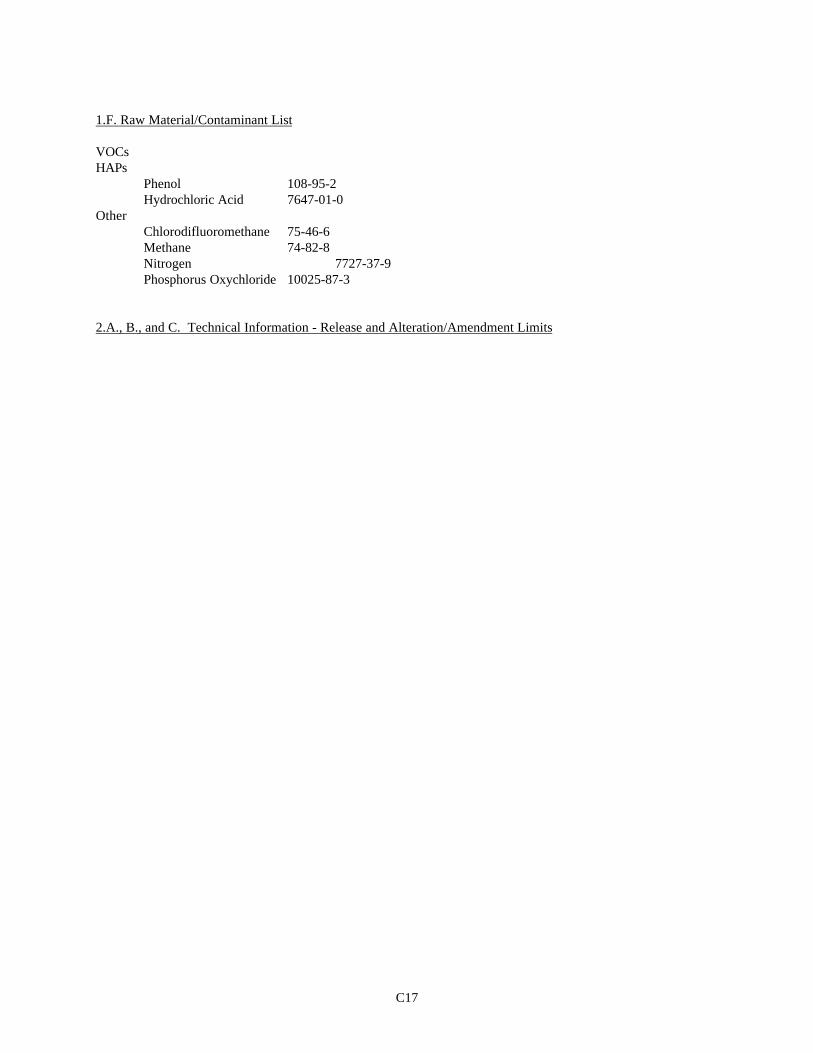
C17
1.F. Raw Material/Contaminant List
VOCsHAPs
Phenol 108-95-2Hydrochloric Acid 7647-01-0
OtherChlorodifluoromethane 75-46-6Methane 74-82-8Nitrogen 7727-37-9Phosphorus Oxychloride 10025-87-3
2.A., B., and C. Technical Information - Release and Alteration/Amendment Limits

C18
Modified 02/18/00
Category: Volatile Organic Compounds OTHER
Sub-Category: HAPS HAPS
Source Constiuent: Phenol Other HCl
Designation Lb/Hr Lb/Hr Lb/Hr
08-OTT-01 Below Threshold
08-PRV-01a 2.3 0.01
08-PRV-02 0.1 0.1 0.01
08-PRV-03 1.5
08-PRV-03a 0.5
08-PRV-04 Below Threshold
08-PRV-05 Below Threshold
08-PRV-06 Below Threshold
08-PRV-07 Below Threshold
08-PRV-08 Below Threshold
08-PRV-09 Below Threshold
08-PRV-10 Below Threshold
08-PRV-11 Below Threshold
08-PRV-12 Below Threshold
08-PRV-13 Below Threshold
08-PRV-14 Below Threshold
08-PRV-15 Below Threshold
08-PRV-16 Below Threshold
08-PRV-17 Below Threshold
08-PRV-18 Below Threshold
08-PRV-19 Below Threshold
08-PRV-20 Below Threshold
08-PRV-21 Below Threshold
08-PRV-22 0.26
08-PRV-23 Below Threshold
08-PTV-01 0.06
08-PTV-03 0.09
08-PTV-04 Below Threshold
08-PTV-05 Below Threshold
08-PTV-06 0.26
08-PTV-09 Below Threshold
08-PTV-22 Below Threshold
08-PTV-23 Below Threshold
08-PTV-24 0.9866
08-STV-02 No lb/hr, Storage Only
08-STV-03 No lb/hr, Storage Only
08-STV-04 No lb/hr, Storage Only
08-STV-05 No lb/hr, Storage Only
08-STV-06 No lb/hr, Storage Only
08-STV-09 Below Threshold
08-STV-10 Below Threshold
08-STV-11 0.15
08-STV-14 Below Threshold
08-STV-15 Below Threshold
08-STV-17 No lb/hr, Storage Only
08-STV-20 No lb/hr, Storage Only
08-TTE-02 Below Threshold
08-TTE-03 Below Threshold
08-TTE-04 Below Threshold
08-TTE-05 Below Threshold
08-TTE-06 Below Threshold
08-TTE-07 Below Threshold
08-TTE-09 Below Threshold
08-TTE-10 0.008 2.984
17-PTV-02 0.15
17-STV-01 No lb/hr, Storage Only
17-STV-02 No lb/hr, Storage Only
17-STV-03 Below Threshold
17-STV-04 Below Threshold
17-STV-06 No lb/hr, Storage Only
Category: OTHER
Sub-Category: HAPS HAPS
Constiuent: Phenol Other HCl
Ton/Year Significant 0.32 10.399 0.074
Ton/Year Insignificant 0.000 0.730 0.000
Ton/Year Fugitive 0.250 1.800 0.100
Lb/Product 7.75E-05 7.70E-04 5.50E-06
Volatile Organic Compounds
Modified 8/9/00

C19
3. Compliance Plan
3.A. Applicable Requirements
The following storage and transfer VOC emission sources are regulated under and subject to the terms andconditions of N.J.A.C. 7:27-8.2(a), 8.3(a through e, h, i and j), 8.4, 8.9, 16.2, 16.4
Significant Sources Insignificant Sources17-STV-06 Butanol Storage Tank
The following process VOC emission sources are regulated under and subject to the terms and conditions ofN.J.A.C. 7:27-8.2(a), 8.3(a through e, h, i and j), 8.4, 8.9, 16.16[b, c, d, g(1,4)], 16.22
Significant Sources Insignificant Sources08-PTV-24 Alcohol Weigh Tank 08-PTV-01b Catch Pot08-PRV-01a HCl Absorber and Vacuum08-PRV-02 Reactor II/III08-STV-11 Phenate Tank17-PTV-02 Phenate Tank08-PRV-05 Mix Pot08-PRV-07 Mix Pot08-PRV-09 Mix Pot08-PRV-11 Mix Pot08-PRV-13 Mix Pot08-PRV-15 Mix Pot08-PRV-17 Mix Pot08-PRV-19 Mix Pot08-PRV-21 Mix Pot08-PRV-04 Decanter08-PRV-06 Decanter08-PRV-08 Decanter08-PRV-10 Decanter08-PRV-12 Decanter08-PRV-14 Decanter08-PRV-16 Decanter08-PRV-18 Decanter08-PRV-20 Decanter08-PRV-03 Steamer Column08-PTV-05 Steamer Overheads Tank08-PRV-03a Batch Dehydrator08-PTV-09 Washer Feed Tank08-PTV-04 Steamer Feed Tank08-PTV-06 Caustic Settling Tank08-PRV-22 Oil/Water Separator08-PRV-23 Oil/Water Separator08-PTV-03 Salt Settling Tank08-PTV-22 Phenate Weigh Tank
The following emission sources are regulated under and subject to the terms and conditions of N.J.A.C. 7:27-8.2(a), 8.3(a through e, h, i and j), 8.4, 8.9
Significant Sources08-STV-17 2-Ethylhexanol Storage Tank08-STV-03 Isodecanol Storage Tank 17-STV-01 EPAL Storage Tank

C20
Modified 11/28/0008-STV-20 Phosphorous Oxychloride Storage Tank08-STV-05 NaOH Storage Tank08-PTV-23 Caustic Mix Tank08-PTV-01 HCl Seal Tank08-OTT-01 Brine Tank08-STV-06 S-148 Product Storage Tank08-STV-02 S-141 Product Storage Tank17-STV-02 S-2148 Product Storage Tank17-STV-03 Day Tank17-STV-04 Day Tank08-STV-09 Day Tank08-STV-10 Day Tank08-STV-14 Day Tank08-STV-15 Day Tank08-TTE-10 Steamer Overheads Loading Spot08-TTE-02 Loading Dock08-TTE-03 Loading Dock08-TTE-04 Loading Dock08-TTE-05 Loading Dock08-TTE-06 Loading Dock08-TTE-07 Loading Dock08-TTE-09 Phosphate Esters Drum Loading
No additional requirements beyond those referenced in the general section of the permit apply to these sources:
Insignificant Sources08-STV-12 HCl Storage Tank08-PCT-01 West Cooling Tower08-PCT-01a East Cooling Tower08-STV-14 Cooling Tower Tank08-STV-15 Cooling Tower Tank17-STV-05 Epoxy Resin Storage Tank08-STV-04 Phenol Storage Tank08-PTV-28 S-148 Storage Tank08-PTV-29 S-141 Storage Tank17-PTV-01 DBPP Storage Tank08-PTV-08 S-214808-PTV-26 Therminol Storage Tank08-PTV-27 Therminol Storage Tank08-PTV-25 Process Surge Tank
3.B. Recordkeeping, Monitoring, and Reporting
1. Recordkeeping
The permittee shall record the following for emissions:a. The date of operationb. Amount of phosphorus oxychloride fed to the reactor system per day
Modified 02/18/00

C21
The permittee shall record pH and flow rates as per 2.a. below. The permittee shall also record calibrationdates as per 2.b. below.
The permittee shall record on a monthly basis and running yearlytotal the throughput of each tank and transfer operation tocomply with the limits with 3.C.1. below.
These records shall be maintained on site for a minimum of five years after the last collection, in apermanently bound log book, readily accessible computer memory, or by another method acceptable to theRegional Enforcement Office. These records must also be available to representatives of the Department.
2. Monitoring
a. The following control devices shall be maintained and operated in accordance with the specificationsdefined in Section 1D of this process package. A double asterisk in the following text denotes that themonitoring equipment is not yet in place. Monitoring and recordkeeping requirements shall not berequired for those parameters until a monitoring device is in place. Upon completion of installation of themonitoring device, monitoring and recordkeeping shall be required.
08-CD-01 Scrubber for Phosphorus Oxychloride Storage Tank (08-STV-20)Venturi – The flow rate of the water at the inlet
shall be monitored and recorded at least onceper day. The flow rate shall be maintainedabove 175 gallons per minute. In the eventthat the flow meter cannot be read, a back-upreading for the inlet water pressure(circulation pump) shall be monitored andrecorded at least once per day. The pressureshall be maintained between 30 and 100 psig.
Packed Tower - The flow rate of the water at theinlet and the pressure drop across thescrubber shall be monitored and recorded atleast once per day. The flow rate shall bemaintained above 100 pounds per minute. Thepressure drop across the packed tower shall bemaintained between 0.005 and 8 inches of watercolumn. In the event that the flow metercannot be read, a back-up reading for theinlet water pressure (circulation pump) shallbe monitored and recorded at least once perday. The pressure shall be maintained between30 and 100 psig.Scrubbing Media (Water) Quality – The density of the scrubbing medium shallbe monitored and recorded at least once per day. The density shall bemaintained between 0.7 and 2.0 grams/cubic centimeter.
b. The permittee shall maintain and calibrate all monitorsconsistent with the manufacturers specifications or otherwritten procedures. All specifications must be made availableto a representative of the Department upon request.

C22
Modified 02/18/00

C23
c. A maximum of 72,300 pounds of phosphorus oxychloride shallbe fed to the reactor system in any one day.
3. Reporting
Release Summary Reports: The permittee shall submit to the Department, beginning from the effectivedate of this permit, a summary of all releases from this process. The requirements of this report aredefined in Section III.D.3.a. of this permit.
3.C. Special Conditions 1. Storage tank 08-PTV-02, chloridate weigh tank, shall be limited to a maximum throughput of 35,000,000
pounds per calendar year of product.
Storage tank 08-PTV-24, alcohol weigh tank, shall be limited to a maximum throughput of 12,000,000 pounds percalendar year of iso-butyl alcohol, 12,200,000 pounds per calendar year of butanol, 10,800,000 pounds per calendaryear of C12–14-16 alcohol, 10,500,000 pounds per calendar year of 2-ethylhexanol, and 12,300,000 pounds percalendar year of isodecyl alcohol.
Storage tank 08-STV-01, POCl3 vent tank, shall be limited to a maximum throughput of 18,000,000 poundsper calendar year of phosphorous oxychloride.
Storage tank 08-STV-02, S-141 storage tank, shall be limited to a maximum throughput of 26,100,000pounds per calendar year of Santicizer 141.
Storage tank 08-STV-03, isodecanol storage tank, shall be limited to a maximum throughput of12,300,000 pounds per calendar year of isodecyl alcohol.
Storage tank 08-STV-04, phenol storage tank, shall be limited to a maximum throughput of 15,000,000pounds per calendar year of phenol.
Storage tank 08-STV-06, S-148 storage tank, shall be limited to a maximum throughput of 26,500,000 poundsper calendar year of santicizer-148.
Storage tank 08-STV-17, 2-ethyl hexanol storage tank, shall be limited to a maximum throughput of10,500,000 pounds per calendar year of 2-ethylhexanol.
Storage tank 08-STV-20, POCl3 storage tank, shall be limited to a maximum throughput of 18,000,000pounds per calendar year of phosphorus oxychloride.
Storage tank 17-STV-01, C12-14-16 alcohol storage tank, shall be limited to a maximum throughput of10,800,000 pounds per calendar year of C12-14-16 alcohol.
Storage tank 17-STV-02, S-2148 storage tank, shall be limited to a maximum throughput of 20,800,000pounds per calendar year of santicizer-2148.
Storage tank 17-STV-06, butanol/isobutanol storage tank shall be limited to a maximum throughput of12,200,000 pounds per calendar year of butanol and 12,000,000 pounds of iso-butyl alcohol.
08-STV-05, caustic storage tank, shall be limited to a maximum throughput of 10,400,000 pounds percalendar year of NaOH.
Modified 5/8/00

C24
08-STV-09, 10, S-141 & S-148 day tanks, shall be limited to a maximum throughput of 26,100,000pounds per calendar year of S-141, and 26,400, 000 pounds per calendar year of S-148.
08-STV-14, 15, DBPP “A” & “B” day tanks, shall be limited to a maximum throughput of 17,600,000pounds per calendar year of DBPP and 6,850,000 pounds of TIBP.
Loading area 08-TTE-10, steamer overheads loading spot, shall be limited to a maximum throughput of500,000 pounds per calendar year of phosphate ester steamer overheads.
17-STV-03, 04, S-2148 north and south Day Tanks, shall be limited to a total maximum throughput of20,800,000 pounds per calendar year of S-2148 product.
08-TTE-02, 03, 04, 05, 06, 07, 09, loading spots, shall be limited to a total maximum throughput of20,800,000 pounds per calendar year of S-2148, 26,100,000 pounds per calendar year of S-141,26,400,000 pounds per calendar year of S-148, and 17,600,000 pounds per calendar year of DBPP,6,850,000 pounds per calendar year of TIBP, and 1,000,000 pounds per calendar year of VOC blendmaterials with a vapor pressure less than E-2 psi.
2. The permittee is authorized to deviate from operating parameters cited in 3.B.2. above for the control devicelisted below for a period of up to ten minutes during routine process maintenance. This maintenance shallinclude such activities as pump changes, checking safety interlocks and alarms, and back flushes.
08-CD-01 POCl3 Tank Scrubber
3. The permittee is authorized to operate the following storage tank without the associated control device for upto a seven-day period if the control device is non-operational. However, no material may be transferred intothe tank during the seven-day period. The control device must be operational within seven days or the tanktaken out of use.
08-STV-20 POCl3 Storage Tank
Modified 06/01/99, 02/18/00

D1
1. A. General Process Description
Benzyl Phthalate Manufacturing Process
Benzyl Phthalate (BzPh) is produced by reacting phthalic anhydride (PA), benzyl chloride (BzCl), and an alcohol.
The PA is mixed prior to introduction to the reactors with an alcohol and triethylamine (TEA). The PA mixtureand BzCl are reacted in a three-stage reactor system. Various alcohols are added to form specialty products.
The entire mixture is decanted and separated into salt, TEA and BzPh. The TEA is recovered in later steps.Byproduct salts are dissolved by HCl. The BzPh is recovered in a series of steps. The salts are sent back forfurther dissolving.
The off gas from the refinement of the BzPh is sent to a thermal oxidizing system.
Additional blending of product is also performed in this process. Products from all processes are blended in thisarea.