faculty of mechanical engineering diploma in …
TRANSCRIPT

FACULTY OF MECHANICAL ENGINEERING
DIPLOMA IN MECHANICAL ENGINEERING
( PROJECT 2 DJJ 6143 )
FINAL REPORT OF :
SMART TROLLEY
PREPARED FOR :
TENGKU MOHD AIZAN BIN TENGKU MOHAMAD
PREPARED BY :
1. ABDUL RAHMAN BIN MAHLI 08DKM18F1024
2. KHAIRUL AMIR BIN AHMAD 08DKM18F1016
3. NUR NABILA BINTI ROSNIZAN 08DKM18F1021
SUBMISSION DATE :
NOVEMBER 8, 2020

POLITEKNIK SULTAN SALAHUDDIN
ABDUL AZIZ SHAH
SMART TROLLEY
ABDUL RAHMAN BIN MAHLI 08DKM18F1024
KHAIRUL AMIR BIN AHMAD 08DKM18F1016
NUR NABILA BINTI ROSNIZAN 08DKM18F1021
A project submitted in partial fulfillment of requirements for the award of
Diploma in Mechanical Engineering
MECHANICAL ENGINEERING DEPARTMENT
JUNE 2020

DECLARATION OF AUTHENTICATION AND OWNERSHIP
TITLE : SMART TROLLEY
SESSION : JUNE 2020
1. We, 1. ABDUL RAHMAN BIN MAHLI 08DKM18F1024
2. KHAIRUL AMIR BIN AHMAD 08DKM18F1016
3. NUR NABILA BINTI ROSNIZAN 08DKM18F1021
are the final year students of Diploma in Mechanical Engineering,
Mechanical Engineering Department, Politeknik Sultan Salahuddin
Abdul Aziz Shah, located at Persiaran Usahawan, 40150 Shah Alam,
Selangor. (here after will be referred as ‘the Polytechnic’).
2. We verify that ‘Smart Trolley’ and its intellectual properties are our original
work without plagiarism from any other sources.
3. We agree to release the project’s intellectual properties to the above said
polytechnic in order to fulfil the requirement of being awarded Diploma in
Mechanical Engineering.
Prepared by
a) ABDUL RAHMAN BIN MAHLI ..………………………………..
(IC No. :000623-13-0099) ABDUL RAHMAN BIN MAHLI
b) KHAIRUL AMIR BIN AHMAD …………………………………
(IC No. : 000221-11-0933), KHAIRUL AMIR BIN AHMAD
c) NUR NABILA BINTI ROSNIZAN ...……………………………….
(IC No. : 001208-141502) and NUR NABILA BINTI ROSNIZAN
at ……………………, on …….………

In the presence of,
TENGKU MOHD AIZAN BIN TENGKU MOHAMAD
(IC No. : 760101-03-5651)
………….……………………...
as the project supervisor on the date: TG. MOHD AIZAN BIN TG MOHAMAD

ACKNOWLEDGEMENT
The success and final outcome of this project required a lot of guidance and assistance from
many people and we were extremely privileged to have got this all along all the completion of our
project. All that we have done is only due to such supervision and assistance and we would not
forget to thank them.
I would like to express my gratitude and appreciation to all those who gave me the possibility to
complete this report. A special thanks to our final year project supervisor, En Tengku Mohd Aizan
bin Tengku Mohamad , whose help , stimulating suggestion and encouragement, helped us to
coordinate our project .
I would like to acknowledge with much appreciation the crucial role of the staff of the mechanical
department, who gave the permission to use all required machinery and the necessary material to
complete the project.
Beside, i would like to thank every member of our group for their cooperative attitude and
dedicated efforts. All of us attend every meeting and everyone shares their constructive opinions
and creative ideas in making this project.

ABSTRACT
This project is applied based on observations on the current manual method of movement and
transfer of items by using bare hands and human energy. The objective of this project is to design
an equipment which is capable to move and transfer items for the use of small-sized industry for
all sectors. In addition, there are a number of scopes for the research which are fixed in this project.
This product only limits for 150 kilograms weight, uses the concept of hydraulic jack to ease the
movement of items and the product was made to compete the current manual method. All of these
are set to address some of the problems that arise with the use of existing methods such as the
difficulty of transferring the item, using a lot of bare hands and less safety factors that cause injuries
from the heavy item. The material of this project has a priority feature that prevents corrosive and
makes the product long lasting, based on the literature review that has been running, and stainless
steel is the most suitable for this project. While for the component formation process, the
methodology studies is used to plan the process of project production with a flow chart as a guide
for project planning and testing. The overall result of this project was achieved with an average
saving of time compared to the traditional method of 50%. Based on these results, the analysis and
discussion that have been carried out, it can be concluded that this Smart Trolley has achieved the
objectives discussed. In addition, this product has been proven to save time compared to traditional
methods.
Keyword: electronic hydraulic jack, comfort, quick

NO. CHAPTER / TOPIC PAGE
1 CHAPTER 1 – INTRODUCTION
1.1 – Introduction
1.2 – Problem statement
1.3 – Objective
1.4 – Scope
1.5 – Contribution
1.6 – Summary of Chapter
1
3
4
4-5
2
CHAPTER 2 – LITERATURE REVIEW
2.1 – Introduction
2.2 – Previous research
2.3 – History
2.4 – Concept of lifting table
2.5 – Component in Smart Trolley
2.6 – Operation Design
2.7 – Summary of Chapter
6
7-9
9-10
10-12
12-13
13
14
3
CHAPTER 3 – METHODOLOGY
3.1 – Introduction
3.2 – Flow chart
3.3 – Methodology Phases
3.4 – Safety Measures
15
16
17-18
19
20-21

3.5 – Protective Clothing and Supplies in
Workshop
3.6 – Project Operational
3.7 – Project Testing
3.8 – Project Refinement Process
3.9 – Project Budget
3.10 – Project Planning (Gantt Chart)
3.11 – Summary Of Chapter
22-23
23
24
24-
25
26-27
28
4
CHAPTER 4 – RESULT & ANALYSIS DATA
4.1 – Introduction
4.2 – Tools Used
4.3 – Results
4.4 – Summary of Chapter
29
29-33
33-34
35
5
CHAPTER 5 – DISCUSSION, CONCLUSION
AND UPGRADE PLAN
5.1 – Introduction
5.2 – Discussion
5.3 – Conclusion
5.4 – Upgrade Plan
36-37
37-38
6
REFERENCE
39

CHAPTER 1
INTRODUCTION
1.1 Introduction
The Smart Trolley idea stood out from many ideas presented by the team based on
how the idea would be developed into an interesting technology product which is convenient,
easy to use and efficient, including it being an add-on service for the hydraulic system. As the
concept was based on technology, it was important to get the insight of consumers for which the
idea was designed. The Smart Trolley idea is based on the observation of small industries that
use a lot of lifting and moving items. The concept is designed into a size of study table. This is
to ease the movement of the Trolley .
This Smart Trolley is installed with a hydraulic jack. A jack is a mechanical device used
to lift heavy loads or apply great forces. A hydraulic jack is a jack that uses a liquid to push
against a piston. This is based on Pascal’s Principle. The principle states that pressure in a closed
container is the same at all points. If there are two cylinders connected, applying force to the
smaller cylinder will result in the same amount of pressure in the larger cylinder. However, since
the larger cylinder has more area, the resulting force will be greater. In other words, an increase
in area leads to an increase in force. The greater the difference in size between the two cylinders,
the greater the increase in the force will be. A hydraulic jack operates based on this two cylinder
system.

1.1.1 Design Principles of Smart Trolley
The Smart Trolley applied the concept scissor lift and hydraulic jack as shown
in Figure 1.
Figure 1.1 : Concept of scissor lift and hydraulic jack
The Smart Trolley applied the concept of scissor lift and hydraulic jack. A motorized
vehicle with a railed platform that can be raised straight up is known as a scissor lift. A scissor lift
is comprised of a base, a series of interlocking accordion-like metal struts and platform that allows
to safely work. Scissor lifts can be powered by petrol, mains electricity or both in the case of a
hybrid model.
The main concept behind a scissor lift is that it will provide the ability to vertically raise
the platform to a desired height by extending its built in. . Criss-crossing metal supports that
elongate as the platform is raised are the basic feature of scissor lifts that distinguishes them
visually from other equipment used to work in higher elevations. The electric that is mounted on
folding arms is used to provide elevated work areas or to help raise or lower unit loads. Scissor
lifts are also portable. They can easily navigate an area via the controls at the top or the bottom.
Once you have reached the desired location, the brakes will be applied in order to lock the entire
unit firmly in place.
A hydraulic jack is a jack that uses a liquid to push against a piston. This is based on
Pascal’s Principle. The principle states that pressure in a closed container is the same at all points.
If there are two cylinders connected, applying force to the smaller cylinder will result in the same
amount of pressure in the larger cylinder. However, since the larger cylinder has more area, the
Hydraulic Jack
Scissor Lift

resulting force will be greater. In other words, an increase in area leads to an increase in force. The
greater the difference in size between the two cylinders, the greater the increase in the force will
be. A hydraulic jack operates based on this two cylinder system.These hydraulic jack is connected
to scissor railed to move the platform upward and downwards controlled by push button.
1.2 PROBLEM STATEMENT
In any physical working environment, employee safety should be the top priority. Many
employees develop back pain over extended periods of heavy lifting. The repetitive motion wears
on their muscles and joints and can take years to fully recover. Employees under these conditions
can also suffer sudden injury. This can happen when the body is tired or one uses an incorrect form
to lift something. The injuries are lasting, painful experiences and may cause an employee to be
out of work or an employer to deal with worker’s comp. All of this can be easily avoided when a
table does the lifting.
Many labor jobs require employees to work on-site, and locations often vary based on the
project. Having a lift table in your mobile toolbox can transform the way you operate on a site. It
brings all the benefits mentioned above right to the place where your work matters most. Moreover,
those who plan to use their hydraulic lift table as a working space will be pleased to see the new
angles they have access to. The machine can handle heavy weight for extended periods of time,
and it only takes a push of a button to adjust its height and angle. This means you can bring
whatever you are working on as high as you want for inspection and lower it back down to get to
work. You may find this new perspective opens doors in your creativity when welding or your
precision in construction cuts.
In addition, a table can usually get the lifting done much quicker than an employee. If you are
working in construction, this means you can get more material up on the structure rather than
loaded around the site. For welding or assembly areas, the ability to easily adjust your working
space can significantly boost how many pieces you work on per day. The machine is not here to
replace your people. Rather, it can ease everyone’s physical workload and be an effective tool to
make a job go by smoother.

1.3 OBJECTIVES OF THE PROJECT
Here are the objectives of the study that can be listed:
i. To design a equipment for a new technique of lifting items activities.
ii. To fabricate Smart Trolley that can increase the productivity and reduce time taken .
iii. To achieve workers satisfaction towards the new technology which proves that it bring
more advantages to them.
1.4 SCOPE OF THE PROJECT
To ensure that this project runs smoothly and achieving the desired objectives, several
scopes need to be followed among others:
i) The first limitation is the small industries . Our product is limited to the small industries
only. Small scale industries are those industries in which manufacturing, providing
services, production are done on a small scale.
ii) The second limitation of this study is the size of the trolley. The size of the trolley is
the same size of table study. Small surface would not enable length equipment.
iii) Affordable to all parties
1.5 CONTRIBUTION
During lifting activity, Smart Trolley are perfect to those who are involves
the activity of lifting goods. This can helps them decrease the burden of lifting goods
without using a lot of energy. Beside, this Smart Trolley are user friendly because
the portable size make it easy to bring it anywhere.

1.6 SUMMARY OF THE CHAPTER
In conclusion, the advantages of Smart Trolley includes easy to use and only need
one person to manage the machine. Beside, the table plate can be adjust according to
desire height. The adjustable part make it easier to move the items. The material is strong
as well as resistance to corrosion, so it is safe and can be used for a long time. The release
of Smart Trolley project will greatly benefit all parties including small industries. May
this project be utilized for mutual benefits workers who do a lot of lifting will able to
contribute more creative and innovative ideas in future projects.

CHAPTER 2
LITERATURE RIVIEW
2.1 INTRODUCTION
This Smart Trolley describes the design as well as analysis of a hydraulic scissor lift.
Conventionally a Smart Trolley is used for lifting to lift the body to appreciable height, and many
other applications Also such lifts can be used for various purposes like maintenance and many
material handling operations. It can be of mechanical, pneumatic or hydraulic type. The design
described in the study is developed keeping in mind that the lift can be operated by mechanical
means by using pantographs so that the overall cost of the scissor lift is reduced. In our case our
lift was needed to be designed as a portable and also work without consuming any electric power
so we decided to use a hydraulic jack pump that is powered by batteries. Also such design can
make the lift more compact and much suitable for medium scale work. Finally the analysis of the
Smart Trolley was done in Ansys and all responsible parameters were analyzed in order to check
the compatibility of the design values.
The conventional method of using rope, ladder lift getting a person to a height encounter a
lot of limitation of time and energy consumption, comfortability, amount of load that can be carried
etc. also there may be a risk of falling down in case of ladders hence Smart Trolley is designed to
overcome all these difficulties. The main aim of this study is design and analysis and to construct
a multipurpose lifting to make the activities efficient. Also the equipment should be compact and
cost effective. With ceaseless development of science and technology, more and more new
technologies are applied to lifting appliance design. This project aims at making equipment
multifunctional, easy to use/operate, cost effective and portable so that it will be used conveniently
at home and may be used in hospitals, hotels and other common places. All safety considerations
are taken into account while designing equipment. Smart Trolley mechanism is designed to lift a
person to desired height. A scissor lift mechanism is a device used to extend or retract a platform
by hydraulic means. The Extension or displacement motion is achieved by the application of force
by hydraulic cylinders to one or more supports. This force results in an elongation of the cross
pattern. Retraction through hydraulic cylinders is also achieved when lowering of platform is
desired.

2.2 PREVIOUS RESEARCH
Elevated work platforms are mechanical devices that are used to give access to areas that
would previously be out of reach, mostly on buildings or building sites. They are also known as
Aerial Work Platforms (AWPs). They usually consist of the work platform itself often a small metal
base surrounded by a cage or railings and a mechanical arm used to raise the platform. The user
then stands on the platform and controls their ascent or descent via a control deck situated there.
Some forms of aerial work platform also have separate controls at the bottom to move the
actual AWP itself while others are controlled entirely on the platform or towed by other vehicles.
Most are powered either pneumatically or hydraulically. This then allows workers to work on areas
that don’t include public walkways, such as top-story outdoor windows or gutters to provide
maintenance. Other uses include use by fire brigade and emergency services to access people
trapped inside buildings, or other dangerous heights. Some can be fitted with specialist equipment,
for example allowing them to hold pieces of glass to install window planes. They are temporary
measures and usually mobile, making them highly flexible as opposed to things such as lifts or
elevators.
However generally they are designed to lift fairly light loads and so cannot be used to elevate
vehicles, generators or pieces of architecture for which a crane would more likely be used. In some
cases however elevated work platforms can be designed to allow for heavier loads. Depending on
the precise task there are various different types of aerial work platform which utilize separate
mechanisms and fuel sources. The most common type is the articulated Elevated Work Platform,
(EWP) or ‘hydraulic platforms’ (and also known as boom lifts or cherry picker). A pantograph is
connected in a manner based on parallelograms so that the movement of one pen, in tracing an
image, produces identical movements in a second pen. If the first point traces a line drawing, an
identical, enlarged, or a pen will draw miniaturized copy fixed to the other. Using the same
principle, different kinds of pantographs are used for other forms of duplication in areas such as
sculpture, minting, engraving and milling.
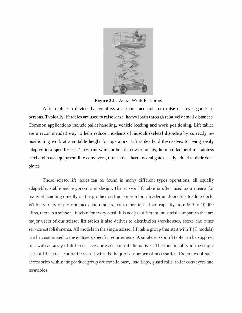
Figure 2.1 : Aerial Work Platforms
A lift table is a device that employs a scissors mechanism to raise or lower goods or
persons. Typically lift tables are used to raise large, heavy loads through relatively small distances.
Common applications include pallet handling, vehicle loading and work positioning. Lift tables
are a recommended way to help reduce incidents of musculoskeletal disorders by correctly re-
positioning work at a suitable height for operators. Lift tables lend themselves to being easily
adapted to a specific use. They can work in hostile environments, be manufactured in stainless
steel and have equipment like conveyors, turn-tables, barriers and gates easily added to their deck
plates.
These scissor lift tables can be found in many different types operations, all equally
adaptable, stable and ergonomic in design. The scissor lift table is often used as a means for
material handling directly on the production floor or as a lorry loader outdoors at a loading dock.
With a variety of performances and models, not to mention a load capacity from 500 to 10.000
kilos, there is a scissor lift table for every need. It is not just different industrial companies that are
major users of our scissor lift tables it also deliver to distribution warehouses, stores and other
service establishments. All models in the single scissor lift table group that start with T (T models)
can be customized to the endusers specific requirements. A single scissor lift table can be supplied
in a with an array of different accessories or control alternatives. The functionality of the single
scissor lift tables can be increased with the help of a number of accessories. Examples of such
accessories within the product group are mobile base, load flaps, guard rails, roller conveyors and
turntables.

Figure 2.2 : Table lifting use in World War 2
2.3 HISTORY
Scissor lifts are a type of aerial work platform (AWP) or mobile elevated work
platform (MEWP), used to provide temporary access at height. They are commonly used for
temporary maintenance purposes and to undertake construction work. Charles Larson, of the USA,
first patented the scissor lift in 1963, but he did not invent it. It was invented by John W Parker of
California.
The first patent request for a scissor lift was filed by Charles Larson of the USA in 1963.
It said that he based the design off the pantograph. JLG was the first U.S. company to make the
scissor lift commercially available. In 1976 JLB company take the Larsons mechanism of an
extendable lift and turn it into an operational machine
The X shape of the pantograph style makes the scissor lift a stable tool for working at
heights. It also makes the extension and collapse of the equipment a lot smoother than with a single
arm. The improved design patented by Charles Larson has been improved over the years with
additional tech advancements. The modern hydraulic system now makes raising and lowering the
platform easier.

Figure 2.3 : Invention of C. L Larson
2.4 CONCEPT OF LIFTING TABLE
It has been the motivation of many concepts and models in theory and industry practice
alike to create and implement successful solutions to the challenging situation described that most
manufacturing companies find themselves in. To present a selection of existing concepts that have
been established in literature and have found application in an industry setting. They are all, in a
general sense, concerned with managing product complexity, and most of them consider product
architecture in one way or another. Although the set of concepts chosen here reflects the current
state of knowledge in the field, it does not mean to be complete as this would be beyond the scope
of this work. The same concept has been used but modification is made. The existing product
before only used a foot pump as a medium to lifting the items. It took time and foot energy to raise
the item from bottom to the top.

2.4.1 Concept 1
A scissor lift, or commonly called a table lift, is mainly used to lift people upwards with its
criss-crossing foundation supporting beneath the platform. As the platform pulls itself together, it
moves upright in the vertical direction and pushes the platform in accordance with the height and
weight. These lifts are controlled through a spindle system. The spindle system is a safer option as
there is no risk of oil leakage, which could cause a tripping hazard Originally delivered in
numerous sizes and shapes, it is designed and manufactured as an industrial lift, and has been
customized for commercial and comprehensive purposes.
However, To fully lift this table it will take 225 Cycles of the handle which take a lot of time and
energy to do the lifting.
Figure 2.4 : Spindle Scissor Lift Table
2.4.2 Concept 2
Foot Pump Lifting Table helps workers raise or lower heavy items to convenient working
levels, helping reduce the risk of strained backs, injured shoulders and pulled neck muscles. These
lifts use air pressure to lift objects. This lift is the most environmentally friendly in comparison to
other lifts because it has no fumes. This works by taking in the surrounding air. They require little
maintenance because of fewer moving parts and no engine. The pneumatic scissor lift works
anywhere since it's only requirement is air. When replacing the Foot Pump Assembly on your

Lange Lift Hydraulic Lift Table, it took less energy than using the spindle system. However this
lift cannot go lower to beneath the platform.
Figure 2.5 : Foot Pump Lifting Table
2.5 COMPONENT IN SMART TROLLEY
i) Up and down switch button
The switch button help to ease the movement
of smart trolley platform upward and
downward. It is connected from batteries
ii) Hydraulic jack
A jack is a mechanical device used to lift heavy
loads or apply great forces. A hydraulic jack is
a jack that uses a liquid to push against a
piston. This is based on Pascal’s Principle.
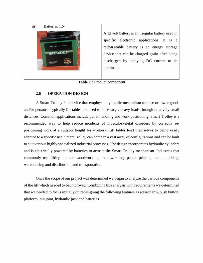
iii) Batteries 12v
A 12 volt battery is an irregular battery used in
specific electronic applications. It is a
rechargeable battery is an energy storage
device that can be charged again after being
discharged by applying DC current to its
terminals.
Table 1 : Product component
2.6 OPERATION DESIGN
A Smart Trolley Is a device that employs a hydraulic mechanism to raise or lower goods
and/or persons. Typically lift tables are used to raise large, heavy loads through relatively small
distances. Common applications include pallet handling and work positioning. Smart Trolley is a
recommended way to help reduce incidents of musculoskeletal disorders by correctly re-
positioning work at a suitable height for workers. Lift tables lend themselves to being easily
adapted to a specific use. Smart Trolley can come in a vast array of configurations and can be built
to suit various highly specialized industrial processes. The design incorporates hydraulic cylinders
and is electrically powered by batteries to actuate the Smart Trolley mechanism. Industries that
commonly use lifting include woodworking, metalworking, paper, printing and publishing,
warehousing and distribution, and transportation.
Once the scope of our project was determined we began to analyze the various components
of the lift which needed to be improved. Combining this analysis with requirements we determined
that we needed to focus initially on redesigning the following features as scissor arm, push button,
platform, pin joint, hydraulic jack and batteries.

2.7 SUMMARY OF CHAPTER
Summary focus of this chapter is to design and build a lift for workers who does the lifting
proses. The current lift is an improvement over the old one. However, there is still room for
improvement. The final design has been utilized. The platform can be adjusted to several heights
and can be extended horizontally forward to the to enhance ergonomics. We determined that a
hydraulic lift would be the best choice for our application. Other design concepts generated include
the wheel locking mechanism, button type, design, hydraulic jack, and power supply.
We began with an design and purchased the hydraulic lift. We had several meetings with
our supervisor to make sure he was pleased with the design, during which she clarified several
design requirements. These meetings led us through several design iterations and finally to our
final design.
Overall obtained from this chapter is an experiment that will be made referring to the
sources of previous studies to complete the work done. In addition, some information from lifting
tools is identified for its function. This implementation can ease to the user of Smart Trolley.

CHAPTER 3
METHODOLOGY
3.1 INTRODUCTION
There are a number of approaches used in this research method design. The purpose of this
chapter is to design the methodology of the research approach through mixed types of research
techniques. The research approach also supports the researcher on how to come across the research
result findings. In this chapter, the general design of the research and the methods used for data
collection are explained in detail. It includes three main parts. The first part gives a highlight about
the dissertation design. The second part discusses data collection methods. The last part illustrates
the general research framework. The purpose of this section is to indicate how the research was
conducted throughout the study periods.
Research methodology is the path through which researchers need to conduct their
research. It shows the path through which these researchers formulate their problem and objective
and present their result from the data obtained during the study period. This research design and
methodology chapter also shows how the research outcome at the end will be obtained in line with
meeting the objective of the study. This chapter hence discusses the research methods that were
used during the research process. It includes the research methodology of the study from the
research strategy to the result dissemination. For emphasis, in this chapter, the author outlines the
research strategy, research design, research methodology, data source and workplace site exposure.
In order to satisfy the objectives of the study, a data research method is apprehended in general.
The study used these mixed strategies because the data were obtained from all aspects of the data
source during the study time. Therefore, the purpose of this methodology is to satisfy the research
plan and target devised by the researcher.
A very significant decision in the research design process is the choice to be made
regarding research approach since it determines how relevant information for a study will be
obtained. The design used field observation at the selected industrial sites. Other than that, data
analysis method follows the procedures listed under the following sections. The data analysis part
answered the basic questions raised in the problem statement. The research methodology and
design indicated the overall process of the flow of the research for the given study. The data
sources and data collection methods were used.
3.2 FLOW CHARTS

3.3 METHODOLOGY PHASES

Our work project goes through few phases. The length and details may vary from project
to project, but all will still follow the same basic framework. While some project
methodologies such as agile approaches compress or repeat the following stages in faster, iterative
cycles, the work of each phase is visible and distinct in every project. Phase, or stages, are very
important for project managers. It is to ensure that the deliverables produced at the end of each
phase meet their purpose. The phases are as follows initiation, planning, execution, design, monitor
and control, and project close.
Firstly, Initiation is a project team formation, project chartering, and kick-off. A solid
project initiation is to set the project up for success. During initiation, the project team members
assigned, brief on the overall project goals, and observe as many workers as possible so we can
plan the project solution based on problem statement efficiently.
Secondly, Planning works as finalizing the project scope, defining the detailed work
breakdown, assessing risk, identifying resource requirements, finalizing the schedule, and
preparing for the actual work. Once we initiated the project and gathered all relevant information,
then begin planning our project. The planning stage depends on the size of our project, with
information we have to organize and the result of planning is a clear project plan or schedule, from
which everyone follow their assigned tasks. Using a project-planning program such as inventor is
extremely helpful when planning a project. Using inventor to create our initial plan and design is
equally as effective.

Then, Execution is performing the actual work required by the project definition and
scope. As we have a solid project plan, our team can begin executing the project against our
assigned tasks. This is the stage where we start doing the work. we want to officially kick off the
execution stage with in person meetings to ensure everyone has what they need to begin executing
their part of the project. Getting the team started on the right track is integral to a project success,
so articulate the schedule and communications plan clearly.
Next is design. In this phase we start the work involved with creating the project's
deliverables, using the project strategy, and Project Initiation Document as starting point. We use
a Flow Chart to create a detailed map of how things will work. At this stage, we must do everything
to think through and deal with project issues before we start to build project deliverables.
After that, Monitor and Control is the actual management, reporting, and control of the
resources and budgets during the execution phase. While the project is in the execution phase, we
begin monitoring and controlling it to ensure it's moving along as planned. There are a variety of
ways we monitor and control a project. Casual check-ins with team leaders, organized formal
weekly status meetings are effective. The information that comes out of these meetings or
communication channels will inform the feedback loop and ultimately any re-planning and
adjustments that may be necessary to the project.
Lastly, Project Close is delivery of the project, assessment of lessons learned, adjournment
of the project team. Once all the details and tasks of our project are completed and approved by
the supervisor we can finally close our project. A project manager will document all the
information from the project and organize it neatly so we can go back to it if necessary. This is
also a good time to hold a post-mortem on the project so all team members can reflect on what
went right or wrong during the project. All important project notes should also be documented so
the outcome can be shared with other project members and filed in a project history folder. Finally,
it is important us to formally adjourn the project team.

3.4 SAFETY MEASURE
Smart Trolley have a variety of uses, especially at small industries. Improper use of Smart
Trolley can cause of quite a few fatalities and accidents over a period of time if the safety measure
is not taken. When working with Smart Trolley it is important to follow proper safety procedures.
Despite the knowledge that the equipment can cause injuries, safety precautions can often be lax.
Below are some tips to ensure heavy equipment is being used safely.
Firstly, It is important to check the equipment regularly to ensure that it is well maintained.
A thorough inspection should be done every year at the very least. Ensure that all the equipment
is tested and certified by proper regulatory bodies. Apart from that we must perform a routine
maintenance. It’s one of the most important safety steps. Make sure routinely test your guardrails,
inspect the workplace environment, and test your workers’ knowledge of safety regulations.
Secondly, All heavy lifting machines have load limits. It is imperative that the load that the
machine is lifting does not exceed these set limits. Our Smart Trolley has a load limit of 150 kg,
loading it with above 150 kg of weight is only creating a recipe for potential disaster. Do not fill
the lift platform beyond its capacity. This includes not carrying materials which are essentially not
allowed to be carried into the work platform. Should there be any exceptions due to the nature of
the work.
Furthermore, the workers should know how to position the Smart Trolley correctly. We
should also eliminate any overhead wires. To be safe, nothing should be hanging over the trolley.
Also, make sure to put down ground guides so that everyone is aware of where the lift is in their
work environment. Familiarize with the manufacturer instructions, and always obey the limits on
both weight and height set by the manufacturer.
Of course, the most important thing can do in order to prevent accidents is to properly train
to use the Smart Trolley properly. This means ongoing training must be done to make sure
everything is as it should be. Make sure you discuss as the basics of handling the scissor lift, How
to spot hazards in the workplace, How to identify when the lift needs repairs, Weight limits. This
will help you to avoid accidents.

3.5 PROTACTIVE CLOTHING AND SUPPLIES IN WORKSHOP
Personal protective equipment used to protects the user against any physical harm or
hazards that the workplace environment may present. It is important because it exists as a
preventative measure that are known to be more hazardous. This includes :
i) Welding Helmet
The welding helmet is generally constructed of
a pressed fiber insulating material.
To minimize reflection and glare produced by
the intense light, the helmet is dull black in
color. Lenses are designed to prevent flash
burns and eye damage by absorption of the
infrared and ultraviolet rays produced by the
arc.
ii) Safety Googles
Safety goggles protect your eyes from weld
spatter which occasionally gets inside the
helmet. These clear goggles also protect the
eyes from slag particles when chipping and hot
sparks when using an angle grinder.

iii) Protective Clothing
Welders should wear work or shop clothes
without openings or gaps to prevent arc rays
from contacting the skin. Woolen clothing
should be worn instead of cotton since wool is
not easily burned or damaged by weld spatter
and helps to protect the welder from changes
in temperature. welding jackets made of
leather, fire-resistant material, or other suitable
material should be worn for protection against
spatter of molten metal, radiated heat, and
sparks.
iv) Gloves
Flameproof gauntlet gloves, preferably of
leather, should be worn to protect the hands
and arms from rays of the arc, molten metal
spatter, sparks, and hot metal. Leather gloves
should be of sufficient thickness so that they
will not shrivel from the heat, burn through, or
wear out quickly. Leather gloves should not be
used to pick up hot items, since this causes the
leather to become stiff and crack.
v) Safety Footwear
It prevents from getting foot injuries due to
slippery surface, heavy falling or rolling
objects, sharp piercing edges, pinch points,
rotary machinery, hot objects, loops of ropes
under tension, splinters, electricity, chemicals
Table 2 : Personal protective equipment

3.6 PROJECT OPERATIONAL
Smart Trolley are used in industrial lifting platforms for transportation of goods, up and
down in workshops and warehouses. Since the goods to be loaded can be heavy in weight. The
safe operation of the scissor lift table is of pretty importance. There are a few way on how to safely
operate a Smart Trolley below :
i) Pre-use Inspection
Firstly, check whether the hydraulic oil is leaking or the oil level is appropriate, refuel if
necessary. Also check whether the battery fluid is leaking and the liquid level is appropriate, add
distilled water as needed. Meanwhile, ensure that all labels are clear, legible, and properly
positioned.
Secondly, check and ensure the components of the Smart Trolley are not damaged,
improperly installed or missing, including the electrical components, wiring, cables, joints,
hydraulic jack, battery packs, drive motors, wheels, nut, bolt, platform overload component, safety
arm, scissor arm pin, fastener, platform control handle, and brake parts.
Finally, find whether the entire Smart Trolley has cracks in welds or structural parts, dents
or damage. Ensure that all structural parts and other key parts are complete, and all related fasteners
and pins are in the correct position and tightened and make sure that the chassis battery tray and
oil pump tray are closed and locked, and the battery is connected properly.
ii) Safe Operation
When operating a Smart Trolley platform equipped with a four-wheel chassis, be sure to run it
on solid and flat ground. Because only four wheel are firmly fixed on a horizontal plane can avoid
the rollover or tilting of the lift platform.
Then, the user must figure out the weight of the items to be loaded. For items that do not
indicate an accurate weight, make an estimate of it. If the weight exceeds the maximum load of
the lifting platform, stop using it because it may cause damage to the Smart Trolley platform.
When transporting goods with Smart Trolley, the heavy loads to be transported must be evenly
placed on the center of the platform. Do not place the heavy objects on one side of the lifting table,
to avoid falling.
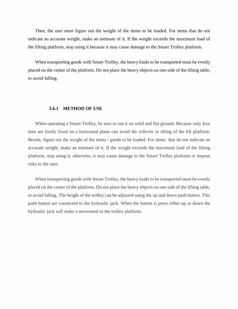
3.6.1 METHOD OF USE
When operating a Smart Trolley, be sure to run it on solid and flat ground. Because only four
tires are firmly fixed on a horizontal plane can avoid the rollover or tilting of the lift platform.
Beside, figure out the weight of the items / goods to be loaded. For items that do not indicate an
accurate weight, make an estimate of it. If the weight exceeds the maximum load of the lifting
platform, stop using it, otherwise, it may cause damage to the Smart Trolley platform or impose
risks to the user.
When transporting goods with Smart Trolley, the heavy loads to be transported must be evenly
placed on the center of the platform. Do not place the heavy objects on one side of the lifting table,
to avoid falling. The height of the trolley can be adjusted using the up and down push button. This
push button are connected to the hydraulic jack. When the button is press either up or down the
hydraulic jack will make a movement to the trolley platform.

3.7 PROJECT TESTING
The purpose of these tests is to ensure that all components and systems are in a satisfactory
and safe condition before start up. Prior to the installation, certain tests and inspections has been
carried out to ensure that proper materials and equipment complying with the specification are
provided and that the site conditions are satisfactory and suitable for the execution of the
installation. Preliminary adjustment and setting of equipment at this stage shall also carried out at
the same time to pave way for the coming functional performance tests.
As a first step, after Smart Trolley was assemble we have done a lifting height testing to
the Smart Trolley. We calculate the highest platform that Smart Trolley can lift. we set up the
trolley to the lowest platform and record the maximum high that smart Trolly can lift. We use
criss-crossing foundation to supporting beneath the platform to reduce the height of the lowest
platform.
Then we move to second step, which is testing the maximum load. Our Smart Trolley
support by hydraulic jack that can lift up to 150 kg of wight. This testing is the most important to
make sure the load does not exceed these set limit or it may cause damage to the Trolley.
3.8 PROJECT REFINEMENT PROSESS
The project comprises of assembling a trolley with hydraulic jack that act as machinery
device. The process started with material that we use which is stainless steel to form a platform for
Smart Trolley. We welded a few parts of the trolley and also use bolts and nuts to joint the parts.
Then, a hydraulic jack is attached to the criss-crossing foundation. To ease the movement of up
and down platform, we use a push button to control the movement. This Smart Trolley is portable
because we use a battery as a power supply. The whole process is depicted in Figure 3.1

Figure 3.1 : Process of making Smart Trolley
3.9 PROJECT BUDJET
Throughout the design process we had to be conscious of the budget. We had roughly RM
300 which is RM100 per person to work with. We must be able to create this new lifting project (
Smart Trolley ) while staying within the budget requirements. Therefore, when selecting the type
of lift to be used we were wary of its cost because this was be the most expensive component of
the table lift. We made sure to set aside enough money so that we could purchase a lift which will
meet our requirements but still leave us with enough money to purchase the other necessary
components such as hydraulic jack , batteries and cable jumper RM 210. With this in mind we
purchased it for . We also purchased the switch button to go with this project at RM 10 and the
wheel for RM6.25 per pairs. Together these five items accounted for roughly run our of our budget.
We therefore had to continue to be conscious of the cost of many of our products. With the changes
in project requirements, we changes the material selection. The most significant of these changes
with regards to cost is the change from mild steel to stainless steel. This change has increased the
cost of the total project budget. However our material to reduce the cost we buy it from the second
hand / used item. The materials for the final design came to roughly RM 20. Therefore the
estimated cost of the project is RM 293.50. For a complete breakdown of the materials budget
please see Appendix B: page 50

3.10 PROJECT PLANNING
TIMEFRAME FOR FINAL YEAR PROJECT 1
Planning date
Execution date
Week
Activity
W
1
W
2
W
3
W
4
W
5
W
6
W
7
W
8
W
9
W
10
W
11
W
12
W
13
W
14
W
15
Division of team members
and project supervisors
Ideas and initial sketches
brainstorming with
supervisors
Presenting Innovation
Detailed hand sketches
3D model with Autodesk
Inventor
Material Selection
Flow Chart
Project improvement
Supervisor confirmation
Project presentation
Proposal report submission

TIMEFRAME FOR FINAL YEAR PROJECT 2
Planning date
Execution date
Week
Activity
W
1
W
2
W
3
W
4
W
5
W
6
W
7
W
8
W
9
W
10
W
11
W
12
W
13
W
14
W
15
Meeting with project
supervisors
Buying materials
Assembly the parts
Product testing
Analysis data
Report submission
Project Presentation

3.11 SUMMARY OF CHAPTER
The chapter provides descriptive and in-depth discussion of the methods involved in the
research of the current study. The current study is looking towards a quantitative approach that
takes into account positivism as it philosophical undertaking, using deductive reasoning for its
interpretive approach. Project operational and project testing are made systematically in the
methodology study to know the facts and information to support the research instrument and
describe it more clearly in this study.

CHAPTER 4
RESULT AND ANALYSIS DATA
4.1 INTRODUCTION
To complete this study properly, it is necessary to analyze the data collected in order to test
the hypothesis and answer the research questions. As already indicated in the preceding chapter,
data is interpreted in a descriptive form. This chapter comprises the analysis, presentation and
interpretation of the findings resulting from this study. Project findings and analysis is a project in
terms of theory or writing related to the function and use of Smart Trolley and their operations
related to the project field. In addition, it should explain the results or results obtained after
implementing a project that is implemented works well or not.
4.2 TOOLS USED
Tool used is a step in the process of designing any physical object. In the context of product
design, the main goal of tool used is to minimize cost while meeting product performance goals.
Systematic selection of the best tool for a given application begins with properties and costs of our
tools. It is essential that a we should have a thorough knowledge of the properties of the materials
and their behavior under working conditions. Some of the important characteristics of tools are
strength, durability, flexibility, weight, resistance to heat and corrosion, ability to cast, welded or
hardened, machinability, electrical conductivity. Apart from that, our product chooses to use
stainless steel as a main material.
Stainless steel is a one of a family of alloy steels usually containing 10 to 30 percent
chromium. In conjunction with low carbon content, chromium imparts remarkable resistance to
corrosion and heat. Other elements, such as nickel, molybdenum, titanium, aluminum, niobium,
copper, nitrogen, sulfur, phosphorus, or selenium, may be added to increase corrosion resistance
to specific environments, enhance oxidation resistance, and impart special characteristics.
Resistance to corrosion and staining, low maintenance, and familiar luster make stainless steel an
ideal material for many applications where both the strength of steel and corrosion resistance are

required. Moreover, stainless steel can be rolled into sheets, plates, bars, wire and tubing. We buy
it for RM 20.00
Figure 4.1 : Stainless steel plate
We also use a spray paint as a finishing product. Spray paint is liquid paint that can be
delivered onto a surface through a spray nozzle. The term is usually applied to paints of various
colors that are available in inexpensive, easily portable aerosol cans. Pressurized gas forces the
paint out of the can in an even stream, usually removing the need for brushes or rollers to distribute
the paint across the surface. Most cans include a ball inside to mix the paint, resulting in the rattling
sound when the can is shaken. It can be used as finishing touch. Beside it can works as prevention
from corrosion. The price for spray paint is RM 5.00.
Figure 4.2 : Spray paint

Jumper cables, also known as booster cables or jump leads, are a pair of insulated wires of
sufficient capacity with alligator clips at each end to interconnect the disabled equipment to
another battery. The alligator clips may be covered in insulation to prevent inadvertent shorting.
Clips may be made of copper or steel. Alligator clips are generally marked by black (−) and
red/orange (+) to indicate the polarity. The cable came with batteries that we buy.
Figure 4.3 : Jumper cables
Beside we use caster type of wheel. The wheel that is designed to be attached to the bottom
of a larger object to enable that object to be moved. They are available in various sizes, and are
commonly made of rubber, plastic, nylon, aluminum, or stainless steel. The price that we buy is
RM 6.25 per pair.
Figure 4.4 : Caster wheel

A switch is an electrical component that can disconnect or connect the conducting path in
an electrical circuit, interrupting the electric current or diverting it from one conductor to another.
The most common type of switch is an electromechanical device consisting of one or more sets of
movable electrical contacts connected to external circuits. When a pair of contacts is touching
current can pass between them, while when the contacts are separated no current can flow. We use
a switch button to move the platform upwards and downwards. It is cost RM10.00
Figure 4.5 : Switch button
We use a 12v batteries as a power supply. It is a rechargeable battery that is used make a
movement to our project. Its main purpose is to provide electric current to the electricity-powered
starting motor, which in turn starts the chemically-powered internal combustion engine that
actually propels the project. The price is RM 41.00.
Figure 4.6 : 12v Batteries

Furthermore, we use hydraulic jack as medium to move the beneath criss-crossing
foundation. Hydraulic jack are pieces of material handling equipment that uses force multiplication
to lift or move heavy loads. The term jacks can refer to a variety of lifting devices that employ
leverage and other methods of mechanical advantage to amplify an applied force to provide the
ability to transport a load. Hydraulic jacks are distinguished by their use of an incompressible
liquid, such as hydraulic fluid or jack oil, as the means by which force multiplication is achieved.
Jacks may be categorized based on the type of mechanism used to generate the lifting force,
typically mechanical power, hydraulic power, or pneumatic power. We buy it for RM200.00.
Figure 4.7 : Hydraulic jack
4.3 RESULT
The scissor lifting machine is tested by lifting three different weights 15, 20, and 30-40 kg
in different heights. The first weight it has lifted is 15kg and it lifts the weight smoothly
without any disturbance. Secondly, it is tested by lifting 20kg; this weight has also been
lifted without any problem and thirdly it has tested lifting 30-40kg this weight also been
lifted without any problem. Generally, the machine can lift the recommended weight 150 kg easily
because the hydraulic piston makes lifting a high load easier and it does not have a disturbing
sound
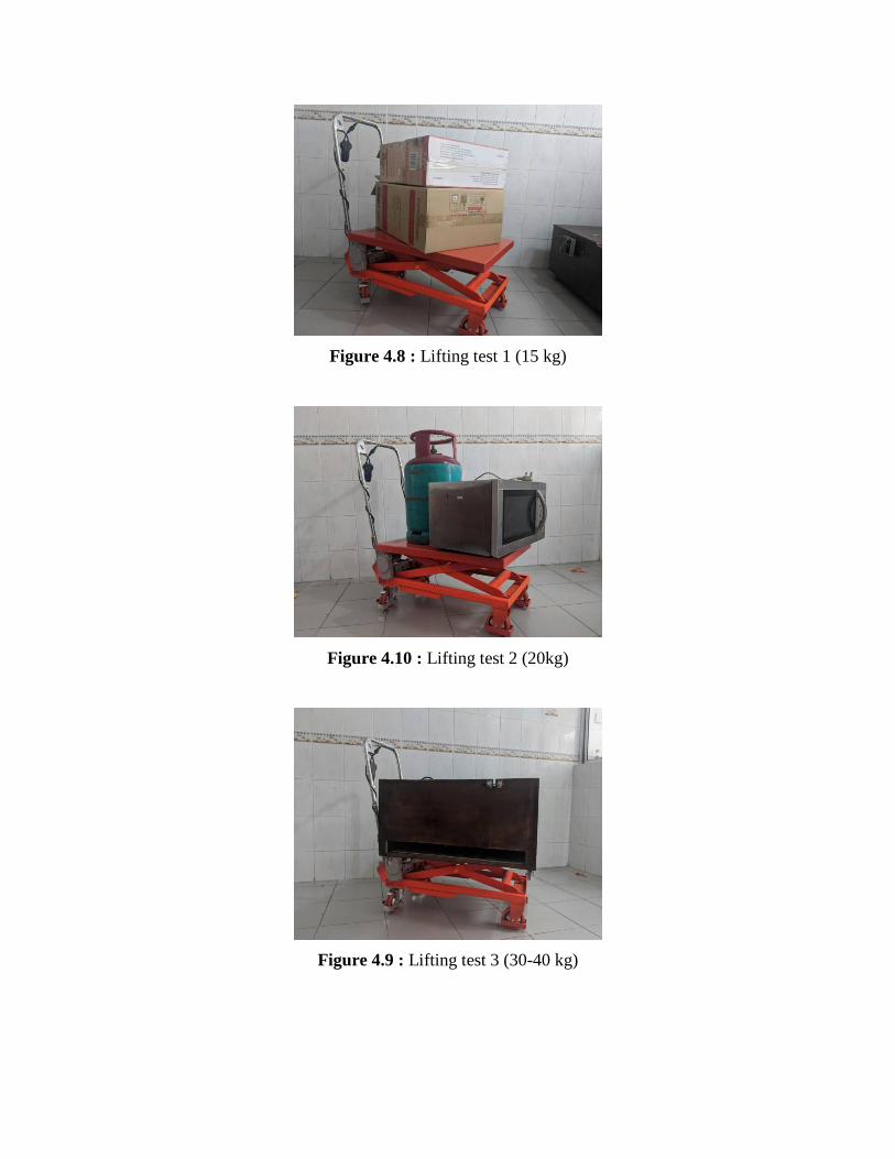
Figure 4.8 : Lifting test 1 (15 kg)
Figure 4.10 : Lifting test 2 (20kg)
Figure 4.9 : Lifting test 3 (30-40 kg)

4.4 SUMMARY OF CHAPTER
This chapter show the tool that we used and the result that we gain after we assemble all
the pats. It was carried out effectively meeting the necessary criteria. The double scissors lift is
operated by the hydraulic jack. The Smart Trolley can be design for average load, because the
higher the load the higher the effort required. The Smart Trolley is easy in use and does not
required tedious repairs. It can also lift heavier loads. For the given dimensions the trolley
can high a load up to 150kg to the height of 720mm.

CHAPTER 5
DISCUSSION, CONCLUSION AND UPGRADE PLAN
5.1 INTRODUCTION
In this chapter, we will discuss and draw overall conclusion on Smart Trolley design and
upgrade plan. This conclusion included design that more ergonomic and efficient in this research.
With this innovation of Smart Trolley, some problems that been faced by visually impaired have
been solved. The discussion about this project is how Smart Trolley related with literature review
that has been made by researcher. There will be more explanation for discussion and conclusion
about Smart Trolley.
5.2 DISCUSSION
Based on literature review, there are various types of hydraulic trolleys sold in the market.
The selection of trolleys on the project should focus on the cost, type, durability and materials
used. we choose a trolley that uses hydraulics. The hydraulics are controlled by electric power to
facilitate the user. We also use stainless steel because an ideal material for many application where
both the strength of steel and corrosion resistance are required. Moreover, stainless steel can be
rolled into sheet, pates, bars, wire and tubing.
Then, we apply a hydraulic at the trolley to facilitate the movement of the trolley. We use
electronic hydraulic jack that controlled by the switch button. Why we choose this hydraulic
because this jack can lift heavy loads (150 kg). This hydraulic jack also use mechanical method.
After that, a 12 volt battery used in this hydraulic for draining power to hydraulic jack movement.
It is a rechargeable battery is an energy storage device that can be charged again after being
discharged by applying DC current to its terminal. This hydraulic is made our project is different
between the trolley at the market.

After that, our trolley is design for user feel comfortable with the trolley. We design this
trolley is more ergonomic and efficient for reduce user from pain. The most important is safety.
After we try our the trolley, we limit the load that can lift for the trolley is 150 kg only. We can’t
take a risk for the user safety.
Lastly, the wheel is one of the important parts because it involves movement. As everyone
knows wheels are used to facilitate movement for our project. Wheel selection is also very
important because it should follow the spec that fits the requirements of the project. We use 4
wheels where the 2 wheels at the back can be locked so that it does not move during the transfer
process.
5.3 CONCLUSION
As conclusion, Smart Trolley makes a significant in terms of safety and productivity. Smart
Tolley are versatile and height-adjustable because of the design. It have myriad benefits, including
the prevention of repetitive stress injuries. The most important we innovation this trolley is because
of safety and less use the human power to carry heavy things that can cause pain.
Beside that, in loading and palletizing jobs, the positioning of the Smart Trolley table at the
required height for a particular job reduces the cycle times by improving the loading efficiency.
To conclude it multiply the reduce cycles multiple times, and across different workstation, it find
that the amount of time saved translates to more productivity.
Laid on the line, our product can give positives impact to user which save time and energy.
Apart from that, lifting the items will be easy. We hope that with the advent of product will help
users to lifting the items easily and can avoid injuries cause by ergonomic systems. Lastly, the
presence of this smart trolley will facilitate the process of moving goods by taking a short time. In
addition, it also does not use full manpower because the innovative design has reduced humans to
produce energy.

5.4 UPGRADE PLAN
Smart Trolley a project innovation that simplifies the process of shifting goods due to its
ergonomic and efficient design. The following are some of the things that are suggested to
further enhance this project;-
1. Use the Solar Systems at battery so that the battery can be recharged naturally after use.
This proposal can save battery and reduce the cost of buying a new battery.
2. Place a barrier such as a cage so that’s thing on the base do not fall while the trolley is
moving.
3. Upgrade the base trolley size more bigger so that it can fit more stuff.
4. Use the hydraulic that can be lift more loads.

REFRENCE
[1] Georgy Olenin , 2016 [online] Available at:
<https://www.theseus.fi/bitstream/handle/10024/113124/Olenin_Georgy.pdf?sequence=1
&isAllowed=y>
[2] Dustin Eusebio, June 6, 2019, [online] Available at:
<https://www.bigrentz.com/blog/types-of-scissor-lifts>
[3] Tool Blog ,February 8 ,2018, [online] Available at:
< https://leagueoftools.com/standard/purpose-and-device-of-a-hydraulic-jack.html>
[4] Wikipedia , [online] Available at:
<https://en.wikipedia.org/wiki/Aerial_work_platform#Scissor_lift>
[5] Wikipedia , [online] Available at:
<https://en.wikipedia.org/wiki/Lift_table>
[6] Specialized Aerial Work Platforms Stretch Makers' Market Share [online]
Available at
<www.constructionequipment.com>, Thursday 1 February 2007

APPENDIX
APPENDIX A Final product
APPENDIX B Cost and expenses
APPENDIX C Poster PITEX
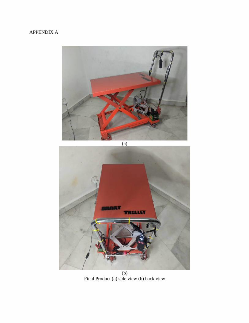
APPENDIX A
(a)
(b)
Final Product (a) side view (b) back view

APPENDIX B
Budget Calculation
No. Materials Price /unit
(RM)
Quantity Total
(RM)
1. Hydraulic Jack 200 1 200
2. Batteries 12v + Jumper cable 41 1 41
3. Push Button 10 1 10
4. Stainless steel 20 1 20
5. Swivel wheel 6.25 2 12.50
6. Spray paint 5 2 10.00
Grand Total 293.50
Table 3: List of Materials and Approximate Expenses

APPENDIX C
Poster Pitex