faculty of physics, mathematics and informatics graduate school … · 2016-07-12 · faculty of...
TRANSCRIPT

Faculty of Physics, Mathematics and InformaticsGraduate School of Informatics
System and Network Engineering MSc
Proving the wild jungle jump
Research Project 2
James [email protected]
July 8, 2015
Abstract
Fault injection has been proven to be a successful attack vector against securesystems and algorithms. It induces faults that are logically not possible in
software. This paper presents results that prove the feasibility of corrupting theprogram counter of the processor using power fault injection. The likelihood ofthe fault model is also expressed. The tests are performed on a widespread
processor, namely the ARM Cortex A9. The tests show that by introducing aprecise drop of power in the voltage line of the processor, assembly instructionscan be skipped or corrupted. This behaviour can cause jumps in memory spaceand can result in code execution controlled by an attacker. This kind of attackcan be applicable against secure devices that are for example implementing
secure boot.
1

Contents
1 Introduction 31.1 Research question . . . . . . . . . . . . . . . . . . . . . . . . . . . 4
2 Scope and contribution 5
3 Related work and background 63.1 Fault injection on ARM . . . . . . . . . . . . . . . . . . . . . . . 63.2 ARM architecture . . . . . . . . . . . . . . . . . . . . . . . . . . 7
3.2.1 Registers . . . . . . . . . . . . . . . . . . . . . . . . . . . 73.2.2 Memory . . . . . . . . . . . . . . . . . . . . . . . . . . . . 73.2.3 Instructions . . . . . . . . . . . . . . . . . . . . . . . . . . 8
4 Test environment and approach 94.1 Test environment . . . . . . . . . . . . . . . . . . . . . . . . . . . 94.2 Methodology . . . . . . . . . . . . . . . . . . . . . . . . . . . . . 10
4.2.1 Glitch generation . . . . . . . . . . . . . . . . . . . . . . . 104.2.2 Determining the result of the glitch . . . . . . . . . . . . . 114.2.3 Possible situation of corrupted PC . . . . . . . . . . . . . 124.2.4 Instrumentation and expected behaviour of the glitch . . 12
5 Results and Analysis 175.1 Glitch influence . . . . . . . . . . . . . . . . . . . . . . . . . . . . 17
5.1.1 Instruction skip . . . . . . . . . . . . . . . . . . . . . . . . 175.1.2 Instruction corruption . . . . . . . . . . . . . . . . . . . . 18
5.2 Conclusion . . . . . . . . . . . . . . . . . . . . . . . . . . . . . . 20
6 Conclusions 21
7 Future work 23
Appendices 26A ARM instruction encoding . . . . . . . . . . . . . . . . . . . . . . i
2

Chapter 1
Introduction
Fault injection attacks are known to be a successful and cheap way to attackembedded systems [12, 14]. Fault injection involves two phases: the injection,that is the attack vector, where the attacker deliberately injects an interferencein the integrated circuit (IC) and the monitoring that proves whether the attackis effective or not. The goal is to change the behaviour of the IC’s operation byusing different injection techniques without destroying the device. The usualpurpose of fault injection is to bypass or corrupt security mechanisms. Thefault injection techniques differ in their domain space, however they all requirehaving access on the IC. These common techniques are:
1. Power fault injection: Introducing unattended glitches in the powersupply to change the behaviour of the IC operation.
2. Clock fault injection: Introducing shorter clock frequency cycles thanthe target ones to shorten the cycles and change the behaviour of the ICoperation.
3. Optical fault injection: Introducing light (i.e. laser) on a specific areaof the IC to change its behaviour.
4. Electromagnetic fault injection : Introducing magnetic pulses usinga probe on a specific area of the IC to change its behaviour.
5. Temperature fault injection: Introducing temperature difference on aspecific area of the IC to change its behaviour.
Fault injections or glitches can be detected but are hard to rule out com-pletely. However, embedded software can be hardened against fault injectionattacks (e.g. checksums, variable redundancy) and hardware can be designedas a countermeasure (e.g. voltage/frequency detectors, active shields)[9, 13].Hardware manufacturers are more and more interested in testing their hard-ware against this kind of attack.
This research is focused on power fault injection and intends to prove if itis possible to corrupt the CPU’s program counter (PC) in such a fashion thatit points to an arbitrary address. This attack vector will be defined as a wildjungle jump in the rest of this paper. The purpose of such an attack is to runarbitrary attacker code on a secure device.
3

1.1 Research question
Overall discussion of the significance and motivation for this project resultedin the following research question:
What is the feasibility of a wild jungle jump?
This research question can be subdivided into several subquestions.
1. How can the PC be corrupted?2. What is the likelihood of a glitch corrupting the PC?
3. What are the repercussions of a corrupted PC?
4

Chapter 2
Scope and contribution
Due to time constraints, the scope of the project had to be carefully defined.The project is targeting a Wandboard Solo [8] that integrates a Freescale i.MX6Solo processor with an Cortex-A9 single core (ARM). This board has beenchosen for its processor that can be found in many embedded devices (e.g Smartphones, smart reader). The project is restricted to the ARM architecture andother architectures (e.g. x86, AMD64) are left out of the scope. The projecthas a practical approach and is only tackling one type of fault injection, that isthe power fault injection.
The project’s main contribution is proving the possibility of corrupting thePC in a controllable way. This paper presents a fault attack that allows runningarbitrary code on an embedded device by modifying the program counter. Thenthe author presents the likelihood of successfully performing a power FI attack.
5

Chapter 3
Related work andbackground
From the early nineties, fault injection was known to be an effective and cheapattack vector for example for smart cards and embedded systems. In the last tenyears an increase in this field of research has been observed. Indeed as system’ssecurity becomes more and more advanced, attackers always tries to find newattack vectors. Fault injection is highly dependent on the targeted hardware.This section describes the previous research related to fault injection on similarinfrastructure and describes in details the targeted ARM architecture.
3.1 Fault injection on ARM
Some research has been done regarding fault injection on ARM based em-bedded devices. Barenghi et al. [10] were the first to perform a successfulpower fault injection attack on a cryptosystem running on a complete operatingsystem.
The processor targeted in this research was an ARM9E (ARMv5TE). Byapplying techniques known in open-literature, they describe the errors inducedin the computation that lead to retrieve all AES round keys, similar results wereobtained when combining a fault injection with a RSA ciphertext attack. Priorto performing their attack they tested the effectiveness of their power faultinjection setup by attempting to infer a computation running on the target.They deduced that the instructions prone to power fault injection attack werethe memory operations. On the other hand, arithmetical and branch operationswere not affected by the power FI. They explained these results due to the lowcapacitance design of the CPU registers; which compensate for the slowdownintroduced by the glitch. This research also highlighted that the load operationwas the only memory operation to report faulty results. The store operationwas not affected by the glitches due to the buffer present in the bus between theCPU and memory; this buffer helps the performing of a correct write operationin memory by reducing the capacitive load. Indeed memory instructions aretransferred through the bus interface; this bus being more power expensive ittends to be more sensitive to the underfeeding in voltage than other instructions.
6
However this does not mean that other instructions are not prone to power faultinjection. Moreover on normal execution the processor does not always transferthe operations between CPU and memory as compilers can optimize the codeto limit this expensive transfer.
Riviere et al [14], successfully performed an electromagnetic fault injection(EMFI) on Cortex-M (ARMv7M) architectures. They created an attack tar-geting the cache instruction that, with the right FI parameters, was highlyreproducible and inducing a fault in up to 96 % of cases. This attack was alsoshown effective against cryptographic algorithms. Finally, another EMFI wassuccessfully performed by Thessalonikefs [16], on the same architecture targetedin this research (Cortex-A9 (ARMv7-A)). Thessalonikefs’s attack resulted intoinstruction skipping, MMU exceptions (that lead to a reset) and wrong valueon the output register.
3.2 ARM architecture
The targeted ARM infrastructure is a 32 bit Cortex-A9 MPCore micropro-cessor. This processor is based on a RISC infrastructure. Due to its presencein many embedded devices such as the iPhone 4S, Apple TV, or the SamsungGalaxy SIII, the Cortex-A9 is an interesting target for this research.
3.2.1 Registers
The processor is based on a RISC infrastructure and has 37 registers arrangedin several banks (User, FIQ, IRQ, Supervisor, Abort, Undefined and System[4]). These banks are determined by the processor mode and this mode changesif an exception occurs. The bank that is the point of interest in this researchis the user bank, where most tasks run. This bank implements 17 registers of32 bit word size to perform operations. These registers have different name andpurposes. R0 to R12 corresponds to the general purpose register used to holdinformation that is used by the processor to perform operations. R13 is thestack pointer, that, as its name implies, points to an address on the stack. It is32 bit word aligned. R14 is referenced as the Link Register that points out whatthe last instruction processed was. The last 15 registers described are specificto the user bank. R15 is the program counter (PC), that points to the processorwhich memory address to execute next and thus determines what the flow ofinstruction for the processor to execute is. The PC is also word aligned and isused by all banks. If corrupted with another address, the PC will effectivelyjump and the processor will start executing from this address; this jump is thetarget of the research. Finally, R17 is the Program Status Register (PSR) thatholds information about the processor while running to report errors in case ofcrash.
3.2.2 Memory
The memory can be seen as two components, the memory and the bus (AMBAAXI). This bus permits access to (store or load) data into memory. Operationsrelated to memory are more expensive computationally and in power than, for
7

example, arithmetic operations. The Cortex-A9 accesses memory using twocaches (L1 or L2) that help translating virtual addresses to physical addressesand speed the memory access. The instruction and data caches are separated[1].
3.2.3 Instructions
In the targeted ARM architecture, the instructions are divided into severaltypes:
• Memory (e.g. load (LDR), store (STR))
• Arithmetic (e.g. add (ADD), substitute (SUB))
• Logical instructions (e.g. move (MOV), and (AND), or (OR))
• Flow control (i.e. branch with link (BL))
The Cortex-A9 implements a variety of instructions that are 32 bits long, thedecoding and meaning of these instructions can be found in appendix A. Theseinstructions are architecture-dependent. When an instruction is received by theprocessor it is first fetched, decoded, executed, then a memory access mightbe required and finally the write back process is performed. This sequentialflow is respecting the von-Neumann model [7]. ARM architectures are ableto do pipelining, meaning that instructions can be processed concurrently orpre-computed.
8

Chapter 4
Test environment andapproach
This section describes the test environment setup and the methodology for theexperiments.
4.1 Test environment
The required resources for this project have been provided by Riscure [6].It includes the Wandboard Solo and some hardware to perform fault injectionsuch as:
1. Picoscope 5203 - Digital oscilloscope used in this research to monitorthe power consumption of the code instructions to determine the correctglitch boundaries.
2. Riscure Glitch Amplifier - Amplifier targeting embedded systems thatrequires a more powerful glitch. It is used to amplify the glitch sent bythe VC Glitcher.
3. Riscure VC Glitcher - Precise and repeatable glitch generator.
The list of software required to carry out this project is:
1. Picoscope 6.0 - Oscilloscope software used to output the results of thevoltage monitoring.
2. Riscure Inspector FI 4.8.3 - Software to define parameters and pro-gram the VC Glitcher.
3. Riscure FI GraphIt 1.0 - Live and Post FI Perturbation VisualizationSoftware
The setup is as presented in figure 4.1. The FI target is a Wandboard thatis running Linux with the Archlinux distribution [3] and the U-boot bootloader[5]. The VC Glitcher is connected to the Glitch Amplifier that is itself hookedto the target board voltage input (Vcc). The VC Glitcher is connected to thereset pin of the Wandboard to have control over the board if a reset is needed
9

during the tests. The VC Glitcher analog glitch line and the Wandboard triggerline are connected to the Picoscope to monitor the Wandboard’s triggers andthe glitch introduced in the IC. Finally, the board is itself connected to theworkstation with a serial cable where Inspector, FI GraphIt and Picoscope arerunning.
Figure 4.1: Schematic overview of the test environment
4.2 Methodology
In order to determine the feasibility of a wild jungle jump, it is essential todetermine an approach for the research. The first step of the research is toget familiar with the power fault injection tools and techniques. Following this,assumptions where a wild jungle jump can be feasible are made. Then assemblycode is implemented to allow the testing of these assumptions. Once the codeis implemented and flashed on the Wandboard, it is to be tested using differentglitch parameters. Finally, the output of these tests are analysed to find theright fault injection parameters (e.g. time, glitch voltage, glitch offsets). Theoutcome of the research is to determine possible situations (i.e. code constructs)where a wild jungle jump is possible. An attempt at establishing a relationshipbetween the fault injection parameters and the code constructs is made.
4.2.1 Glitch generation
The glitch is the cause of the PC corruption. It is dependent on several param-eters that need to be finely tuned to allow increasing the likelihood of such ICbehaviour. These parameters needed to be tuned are detailed below and arerepresented in a schematic form in figure 4.2 :
1. Glitch voltage: power pulse or drop injected in the IC (Measured in Volts).
2. Glitch offset: Time to wait after a clock cycle phase before sending a glitch(in microseconds).
10

3. Glitch cycles: The number of cycles targeted by the glitch.
4. Wait cycles: The number of cycles to wait before sending a glitch.
5. Glitch length: Length of the power pulse injected in the IC (in microsec-onds).
The fault injection inserted in the IC is expected to be tuned in such a fashionthat the chances of corrupting the PC are higher. In order to find the best pa-rameters for the targeted instrumentation the glitch parameters will be definedin a certain range and swept through using a random pattern using Inspector.This method has proven to be one of the most successful [11]. These testingswill allow to determine where the PC corruption is more likely to happen. Thenthe parameters will be narrowed to increase the success rate.
Figure 4.2: Representation of the glitch parameters needed to perform a powerfault injection
4.2.2 Determining the result of the glitch
An inspector module, written in java, is the core of the FI test. It sends thecommand to the board (through the serial connection), performs the glitchusing the defined parameters and outputs the result in a SQLite database. Italso allows for control of the board in case it is not responding (i.e. boot loop)and sends a reset to the board.
To analyse the result of the tests, the written java module differentiates theexpected result of the glitch from the expected result of the instrumentation, theresets and the abnormal behaviour of the processor (e.g. data abort, undefinedinstruction). These selections allow for an overview of the test and enable betterunderstanding of the processor behaviour, depending on the parameters set forthe test. The module outputs these results with an associated color to a SQLitedatabase that is then crawled by the FI GraphIt tool to produce readable graphsand enables analysis of the database file in a readable manner.
11
4.2.3 Possible situation of corrupted PC
A program counter can be corrupted in many manners, however the likelihoodfor it to happen is highly dependent on the processor infrastructure, the glitchparameters and the present code. Assumptions of the most probable ways ofcorrupting a PC are presented in this section.
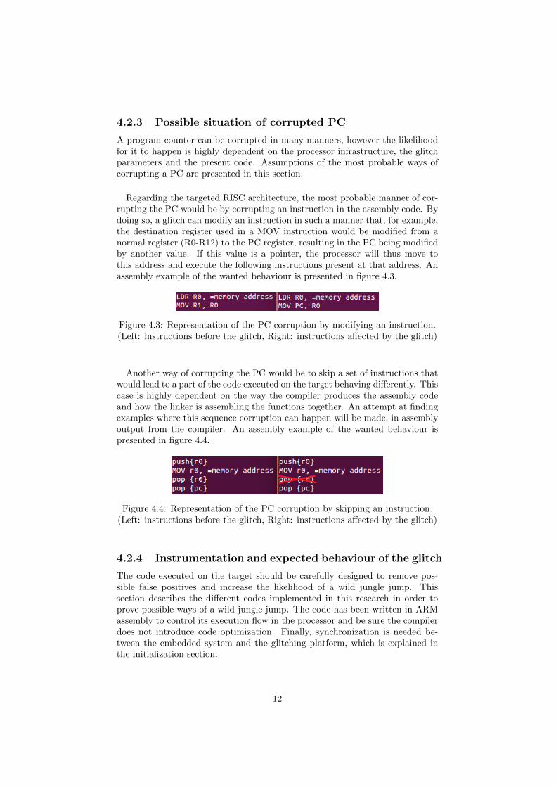
Regarding the targeted RISC architecture, the most probable manner of cor-rupting the PC would be by corrupting an instruction in the assembly code. Bydoing so, a glitch can modify an instruction in such a manner that, for example,the destination register used in a MOV instruction would be modified from anormal register (R0-R12) to the PC register, resulting in the PC being modifiedby another value. If this value is a pointer, the processor will thus move tothis address and execute the following instructions present at that address. Anassembly example of the wanted behaviour is presented in figure 4.3.
Figure 4.3: Representation of the PC corruption by modifying an instruction.(Left: instructions before the glitch, Right: instructions affected by the glitch)
Another way of corrupting the PC would be to skip a set of instructions thatwould lead to a part of the code executed on the target behaving differently. Thiscase is highly dependent on the way the compiler produces the assembly codeand how the linker is assembling the functions together. An attempt at findingexamples where this sequence corruption can happen will be made, in assemblyoutput from the compiler. An assembly example of the wanted behaviour ispresented in figure 4.4.
Figure 4.4: Representation of the PC corruption by skipping an instruction.(Left: instructions before the glitch, Right: instructions affected by the glitch)
4.2.4 Instrumentation and expected behaviour of the glitch
The code executed on the target should be carefully designed to remove pos-sible false positives and increase the likelihood of a wild jungle jump. Thissection describes the different codes implemented in this research in order toprove possible ways of a wild jungle jump. The code has been written in ARMassembly to control its execution flow in the processor and be sure the compilerdoes not introduce code optimization. Finally, synchronization is needed be-tween the embedded system and the glitching platform, which is explained inthe initialization section.
12

Initialization
In order for the platform to detect the critical section targeted by the glitchsynchronisation is needed. To allow this the section is delimited by power trig-gers using gpio output. The triggers can go from a high power line to a lowerpower line (or vice verca), one is set before the critical section and is then re-stored to its initial value after it using a second one. These triggers are usedas a time synchronization point between the target and the attacker. As thetrigger is not immediate and takes some micro seconds to reach its lower powerline, another initialization is needed to compensate for this time in the criticalsection (See delta in figure 4.5). To compensate, some no operations (NOP) arecomputed before entering the critical section, permitting the glitching hardwareto be synchronized and ready to glitch.
Figure 4.5: Trigger delay measurement
Instruction skip characterization
The first instrumentation intends to prove the possibility of skipping instructionswith power fault injection. The goal is to characterize if instructions can beskipped by introducing a glitch without disrupting the execution of the code.The critical section in this implementation is an unrolled loop that incrementsa counter. The end of the critical section returns the counter and a recognizablestring is printed when finished. The length of the skip can be then deduced bysubtracting the value of the counter from the length of the loop.
Gluing functions using instructions skip
The second test intends to prove the possibility of gluing functions together byskipping a set of instructions. The goal of this instrumentation is to skip the endand the start of two functions that are closely located in memory. This modelintends to prove that old values present in the registers in the first function canbe reused in the second one. To prove such fault a precise number of instructionsneed to be skipped. The target of the glitch is to skip the register flush and setand thus to execute an address that has been loaded into a register in the firstfunction.
13

If this test results in proving the model to be successful, an attempt will bemade to find a real sequence that could be corrupted in compiled open sourcecode. If an instruction is found to be able to be corrupted or skipped, the projectwill have a real life implementation. The purpose of this is to find a possibleweakness proving the research target on a code that is already compiled andused. It is important to mention that the reason for which the author focuseson already compiled code is that the assembly code produced depends on thecompiler (version or chain) used. Using an already compiled code removes theproblem of the code being compiler dependent.
Instruction corruption characterization
The second set of instrumentations was implemented in such a way as to provethe likeliness of a instruction being corrupted, by replacing in the destinationfield a general purpose register (R0-R12) by the PC register (R15). To confirm asuccessful glitch, a payload function returning an identifiable string when calledis inserted in a farther part of memory. The main function targeted by theglitch is not calling this function but is performing a variety of MOV operationsbetween the registers that hold the location of this function. To call the payloadfunction, the location of this function should be loaded into the PC and thatis the expected fault model for the glitch. An example representing the desiredbehaviour is presented in figure 4.6. In this example the expected behaviourafter a successful glitch would be to change the value of R1 into the PC soit jumps to another location in memory. Another more realistic test using thisfunction was performed with a single MOV operation and will be the final targetof this fault model.
Figure 4.6: Schematic representation of the code behaviour when successfullyglitched. (Left: code in normal usage, Right: code affected by the glitch)
14

It is important to mention that when linked, functions are more likely to endup close to each other. As glitches are also likely to skip a certain number of lines,it is necessary to move the payload function to a further location in memory sothe tests will not result in false positives. To do so a consequent number of NOP(no operations) were added between the payload and the executed function. Thecode was also adapted to distinguish if the result of a successful glitch is due toa skip or an instruction corruption. The memory was laid out in such a mannerthat if a skip happened the processor would result in going to the second payloadfunction, located under the first one. To do so, a branch with link (BL) pointingtowards the second payload was placed after the end of the critical section andbefore the first payload function. If the processor jumped to the second payloadfunction it would then mean that a sequence had been skipped or the value ofthe register holding the address had been modified by the glitch to an addresslocated between the critical section and the BL to the second payload function.A representation of the memory layout is presented in figure 4.7.
Figure 4.7: Schematic representation of the memory layout
Corrupting the PC during a memory copy
As explained by Barenghi et al [10], fault injections are more likely to be suc-cessful on memory operations and more precisely on load instructions due tothe fact that these instructions are more power expensive and thus more proneto fault injections. The expected behaviour of this fault model is the same as inthe instrumentation discussed above. The implemented code should be relevantto normal use cases and, as most assembly code is produced using a compiler,the results of this research would be more meaningful if the tested instructionswere likely to be produced by this compiler. The second instrumentation is thenimplementing a memory copy. This memory copy will be referred to as memcpyin the rest of the paper. This type of function was chosen due to its operations.
15

A memcpy meets the requirements for the fault models targeted in the instruc-tion corruption as indeed it uses a source and a destination memory address asan input and performs a load (LDR) and store (STR) instruction to copy fromflash/memory to memory. In order to increase the likelihood of a successfulglitch, the address being copied is an array of pointers to the attackers code.This means that every word copied, containing the attackers code address, willbe a single load instruction. A schematic representation of the instrumentationand its expected behaviour after a successful glitch is represented in figure 4.8.
Figure 4.8: Schematic representation of the LDR corruption behaviour whensuccessfully glitched. (Left: code in normal usage, Right: code affected by the
glitch)
16
Chapter 5
Results and Analysis
This section analyses the results of the test performed on different code imple-mentations and tries to explain their causes and consequences. The results aresummarized into a possible attack model. The likelihood of every fault modelbeing accurate is also expressed. It is essential to mention that in fault injectionany fault model that has a likelihood that is not null means that it is successful.This likelihood can be expressed in percentage of success. The likelihood offinding exploitable code in open source implementations is also expressed.
5.1 Glitch influence
The following section describes the influence of the glitch on the different in-strumentations produced and tries to derive conclusions on the cause of theseglitches.
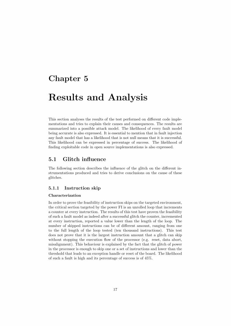
5.1.1 Instruction skip
Characterization
In order to prove the feasibility of instruction skips on the targeted environment,the critical section targeted by the power FI is an unrolled loop that incrementsa counter at every instruction. The results of this test have proven the feasibilityof such a fault model as indeed after a successful glitch the counter, incrementedat every instruction, reported a value lower than the length of the loop. Thenumber of skipped instructions can be of different amount, ranging from oneto the full length of the loop tested (ten thousand instructions). This testdoes not prove that it is the largest instruction amount that a glitch can skipwithout stopping the execution flow of the processor (e.g. reset, data abort,misalignment). This behaviour is explained by the fact that the glitch of powerin the processor is enough to skip one or a set of instructions and lower than thethreshold that leads to an exception handle or reset of the board. The likelihoodof such a fault is high and its percentage of success is of 45%.
17

Gluing functions and fault model likeliness in compiled code
The first goal of this instrumentation was to prove that instruction skip can beused to glue two functions together and that registers set in the first functionscould be reused in another function. This fault model has been proven successfulwhen a precise amount of instructions are skipped. In the instrumentationcreated the fault injection resulted in a wild jungle jump. The likelihood ofsuch a fault is lower as the glitch is targeting a skip on a certain amount ofinstructions only. The percentage of success for this test is 0.01%. Due to timeconstraints, a second FI test with narrowed parameters has not been performed;thus this success rate could not be raised.
However this implementation is really specific; that is why attempts weremade to find examples of such operations where an attacker could have controlover the address in the first function in already compiled code. The goal was tofind weaknesses in code without the chain dependency of the compiler. Despitean in depth code walkthrough in two related ARM code implementation (U-bootand busybox) no possible wild jungle jump has been found for this situation.This does not mean that this fault model could be reused for other purposes,such as to change the output value of a function by changing its register set.
5.1.2 Instruction corruption
Characterization: Moving a variety of register
The third test, that had for goal to corrupt an instruction, has proven thefeasibility of corrupting a normal purpose destination register into the PC reg-ister during a MOV operation. During this test it was feasible to change thedestination register to the PC, resulting in the value contained in the sourceregister being loaded in the program counter. This glitched instruction resultedin the processor jumping to the target address held in the source register. Thetests have been performed over a variety of registers sorted by destination reg-ister number. The successful glitches tend not be correlated with time, so it isthus safe to say that the glitch does not have a time dependency regarding thefunction. Which induces that the glitches are not more successful on differentregisters. The likelihood of creating such a fault is low however compilers oftenuse this kind of instructions as they are less expensive than memory instructions.The success rate of this test was raised at most at 0.16%.
Moving one register
After moving towards a more realistic approach, with a single MOV instruc-tion, the same results were observed as for the variety of registers. However anunusual behaviour was noticed as some registers are more prone to be changedinto the PC register. The goal of the glitch is to flip/keep all bits of the destina-tion registers at one. It resulted that as an example no successful glitches werenoticed when the destination register was set to ’0111’ (R7), however successfulglitches happened when the register was set to ’0110’ (R6). This behaviourcould not be explained and could not be further researched due to time con-straints. The success rate when using the R6 destination register was raised to5%. This implementation has been proven more likely to happen as the time to
18

perform the function is reduced; it is more likely to introduce the correct glitch,thus flipping the correct bits at the right time.
A real life example of the instruction corruption model is present in the U-bootsource code (Figure 5.1). This example has not been tested however, it would belikely to be exploitable and it would be relevant to many implementations. Thefunction is a cyclic redundancy check (CRC). It does respond to the requirementsas it loads into a register a value that the attacker has control of. This valuecan be for example data stored in flash. The other requirement is also respectedas the function is moving this value into another register. However it doesnot implement a normal MOV but a MVN that corresponds to a normal moveoperation with a bitwise logical NOT operation on the value held in source. Soif the malicious code is located at 0xFF00 (1111 1111 0000 0000) the computedCRC should be equal to 0x00FF (0000 0000 1111 1111). In order to execute thearbitrary code three steps would be required:
1. Locate the malicious code address.
2. Craft the data in such a way that the CRC computation results in theinverse of the address pointing to the malicious code.
3. Perform power FI on the CRC function to modify the R0 register to thePC register.
The success of the FI is not likely as the probability for the glitch to flip fourbits from zero (R0) to one (PC) is low. However it is possible and this behaviourhas been seen during tests.
Figure 5.1: Code source of the CRC32 function
Targeting the memcopy
The goal of the memcopy implementation is to prove the feasibility of an in-struction corruption on a load operation. It results that a load operation canalso be the target of a instruction corruption where the destination address isset to the PC. The result of this instruction corruption is the same behaviouras the instruction on a MOV operation where a wild jungle jump is performed.The success rate for this test is of 3.4%. The test showed that the likelihood forthis corruption to happen is low. Similar code can be found in most Unix-like
19

system. The memcopy gives the opportunity to the attacker to have controlover the source and destination. In the attack performed the source is an ar-ray containing multiple time the start address value of the attacker’s code. Bycopying this value from source to destination it is possible to introduce a glitchthat modifies an instruction in such a way that the address value is loaded intothe PC register; resulting in the execution of the attacker’s code. This exampleproves that it can be possible to run arbitrary code on a secure device usingFI. Moreover in the first step of secure boot implementation, memory copy areoften used to copy from memory to flash.
5.2 Conclusion
The possibility of corrupting the program counter by skipping instructions hasbeen proven to be a feasible attack vector. Combined with the right fault injec-tion parameters this FI can result in gluing two functions together, resulting inthe execution of a function with the registers value set in the previous function.To reproduce such an attack on different targets dependencies arise; as indeedthis attack model is highly dependent on what the compiler does as any differentversion of compiler or chain will give a different assembly output. To prove thelikelihood of such attack models in real life without these dependencies, somealready compiled code, available in the open source community was studied.Situations where an attacker had control over a source that would result in aregister and this register being reused in a following function could not be found.
The move (MOV) and load (LDR) operations have been proven successfulattack vectors for a wild jungle jump as indeed when successfully glitched it ispossible to jump to the targeted code by using fault injection. This situation isdependent on the code structure. The requirement for the code structure is thatit implements the operation (MOV or LDR) with as a source a pointer addressthat the attacker has control of. An example of such a code is the CRC32function or the memory copy case. These addresses or pointers are movedfrom memory to registers and it is from these instructions that the attack wasdesigned.
20

Chapter 6
Conclusions
This research goal was to estimate the likelihood of a program counter cor-ruption with the use of power fault injection on a low power computer thatimplemented a widespread processor (ARM Cortex-A9).
The results have shown that it is feasible to corrupt the PC in different ways,resulting in the execution of code located at a control address (by an attacker).This research also resumes the most probable way of corrupting the programcounter using fault injection and explains the likelihood of the fault model pres-ence in already compiled code.
The first fault model proven feasible is the instruction skip. Indeed a powerglitch, introduced with the right parameters, can result in the skip of a singleor a large amount of instructions. The success rate of the test that proved thismodel successful is of 45%. This fault model can be used to glue functionstogether resulting in old register value being executed by the processor. Thesuccess rate for the test proving this model successful is of 0.1%.
The second fault model proved that it is feasible to modify a single instructionin such a way that a normal purpose register, used to perform internal processoroperation, can be modified to the PC. The success rates of the tests that provedthis model successful is of 5% when corrupting a MOV instruction and 3.4% forthe LDR instruction. This model has proven that if, in a function, an attackerhas control over the source or destination address in memory it is possible toperform a wild jungle jump, resulting in the code located at the targeted addressbeing executed. This situation could happen in the CRC32 U-Boot function orin the memory copy example that has been proven feasible in this research.The memcopy function can be coded in several ways to enhance performanceand most of these different functions, presented in the ARM support knowledgearticles [2], are also vulnerable to this fault model.
Finally code has been analyzed to find possible real life scenario where a setof instructions can be skipped in such a fashion that the previous value held ina register (preferably a controlled pointer) is moved into the program counter
21

instead of the skipped value. However, this situation could not be found in theexamples analysed.
To conclude a wild jungle jump has been proven feasible using power FI inthe test cases evoked above; however there is a low likelihood of reproducingsuch a fault on another device as it is highly dependent on the compiler (versionor chain) used and requires having an understanding of the assembly code andthe layout of the memory. Moreover finding the right parameters for the FI canbe tedious as it requires long and precise testing.
22

Chapter 7
Future work
As future work the author would recommend proving that a wild jungle jumpis also feasible on other architectures such as x86, MIPS or AMD. Another in-teresting topic that has not been investigated in this research is the countermea-sures against the program counter corruption. Last but not least, the feasibilityof a wild jungle jump could be proven doable using other FI techniques such asEMFI or optical FI.
Finally, fault injection is becoming a topical trend and is a feasible attackvector against embedded systems as proven in this research. That is why it isimportant to raise awareness about FI attacks and their applicability to securedevices.
23

Bibliography
[1] Cortex-A9 technical reference manual. http://infocenter.arm.com/
help/index.jsp?topic=/com.arm.doc.ddi0388f/Caccifbd.html, 2010.
[2] What is the fastest way to copy memory on a cortex-a8?, ARM technicalsupport knowledge articles. http://infocenter.arm.com/help/index.
jsp?topic=/com.arm.doc.faqs/ka13544.html, 2011.
[3] Archlinux – a simple lightweight distribution. https://www.archlinux.
org/, 2015.
[4] The arm instruction set. http://simplemachines.it/doc/arm_inst.pdf,2015.
[5] Das U-Boot – the universal boot loader. http://www.denx.de/wiki/
U-Boot, 2015.
[6] Riscure. https://www.riscure.com/, 2015.
[7] von-Neumann architecture. https://en.wikipedia.org/wiki/Von_
Neumann_architecture, 2015.
[8] Wandboard. http://www.wandboard.org/, 2015.
[9] Naccache Tunstall & Whelan Bar-El, Choukri. The sorcerer’s apprenticeguide to fault attacks. 2004.
[10] Koren & Naccache Barenghi, Breveglieri. Fault injection attacks on cryp-tographic devices: Theory, practice, and countermeasures. 2012.
[11] Batina Menarini Jakobovic Boix Carpi, Picek and Golub. Glitchit if you can: parameter search strategies for successful faultinjection. http://cardis.sec.t-labs.tu-berlin.de/proceedings/
CARDIS2013_16.pdf, 2013.
[12] Jovanovic & Polian. Kumar. Precise fault-injections using voltage and tem-perature manipulation for differential cryptanalysis. 2014.
[13] M. Oostdijk M. Witteman. Secure application programming in the presenceof side channel attacks. 2008.
[14] Rauzy Danger Bringer & Sauvage. Riviere, Najim. High precision faultinjections on the instruction cache of ARMv7-m architectures. 2015.
24

[15] Ryan. Decoding the arm instruction set. http://emucode.blogspot.nl/
2010/09/decoding-arm-instruction-set.html, 2010.
[16] Thessalonikefs. Electromagnetic fault injection characterization. 2014.
25

Appendices
26

Appendix A
ARM instruction encoding
This table[15] describes how the instruction are encoded in ARM. The instruc-tion are 32 bit long and have all a different purpose.
Figure A.1: ARM instruction set encoding
i