failure analysis of h13 gear blank forging dies · pdf filefailure analysis of h13 gear blank...
TRANSCRIPT

Failure Analysis of H13 Gear Blank Forging Dies
John C. Bergeron, Erin Burns, John Bushie,
Haakon Sandberg, Abby Vanden Heuvel
Department of Materials Science and Engineering Michigan Technological University
Houghton, MI 49931
Advisors: Dr. Doug Swenson, Dr. Walt Milligan
Industrial Partner Andy Carrico Walker Forge 250 Spring Street Clintonville, WI 54929
May 22, 2004
2
TABLE OF CONTENTS Abstract ................................................................................................................................3 1.0 Introduction....................................................................................................................4 2.0 Background....................................................................................................................4 3.0 Die Failure information…………………………………………………………....9-11 4.0 Research Objectives............................................................................................... 11-12 5.0 Visual Examination................................................................................................ 12-13 6.0 Test Procedures...................................................................................................... 14-15 7.0 Results and Discussion .......................................................................................... 16-21 8.0 Conclusions..................................................................................................................23 9.0 Recommendations........................................................................................................23 10.0 References..................................................................................................................24
3
Abstract The objective of the failure analysis project was to investigate and realize the mode and cause(s) of premature failure of forging dies composed of pre-hardened H13 stock. The forging operation also uses a vacuum heat treated stock for these dies. Vacuum heat treating of the stock is performed in-house and premature failures have seldom occurred when the vacuum heat treated stock is utilized. A variety of testing and background research on topics such as metallography, hardness, fractography, and fracture toughness has provided several possible solutions to the failure analysis problem. Scanning Electron Microscopy has revealed oxide inclusions near the suspected failure initiation point(s). Results from these previous tests suggest higher fracture toughness in the vacuum heat treated stock, and this hypothesis shall be tested by fracture toughness testing. This hypothesis was confirmed by four point bend fracture toughness testing. The vacuum heat treated stock displayed a fracture toughness of 47 MPa√m, while the pre-hardened stock was 34 MPa√m. Essentially, the fracture toughness of the pre-hardened stock was approximately 75 percent of the fracture toughness of the vacuum heat treat. Current research has shown machining the dies may produce cracks on the surface of the forging dies. Once the dies are in service, these machining cracks act as stress concentrators and cause catastrophic failure of the die. The mode of failure has shown low cycle, high stress fatigue behavior, with the fracture propagating to complete failure in very few cycles.
4
1.0 Introduction Forging is defined as the process of working hot metal into a desired shape by impact or pressure.1 The hot metal is formed into shape using dies that have the desired geometry machined onto their surfaces. Ultimately, a die will simply wear out-of-tolerance over time and use; however, several failures, such as heat checking (when the die surface is overheated, while the center of the block is cool) and gross cracking, may cause the dies to fail before they should. The premature failure of forging dies costs the forging industry millions of dollars each year. When a die fails, the process produces flawed parts and decreases quality. Also, these dies have a high initial cost due to raw material, tooling, machining, and computer analysis costs. Therefore, the industry is seriously affected by these failures. Walker Forge, Inc. is one of many forging companies that experiences these die failure issues. Particularly, Walker Forge Inc. is struggling with the shortened life of forging dies used to produce gear blanks (composed of superior or premium grade H13 tool steel). These gear blank forging dies, which Walker Forge, Inc. manufactures on-site, produce a high volume of parts; therefore, die life expectancy is imperative for financial and production reasons. Specifically at Walker Forge, Inc., premature die failure is only a consistent problem with forging dies composed of pre-hardened H13 stock. The forging operation also uses a vacuum heat treated stock for these forging dies, and premature failures have seldom occurred when the vacuum heat treated stock is in service. Vacuum heat treating of the stock is performed in-house (by Walker Forge, Inc.). This report will entail a detailed account of the research that has been performed in order to realize a mode of failure as well as recommendations to reduce future premature die failure at Walker Forge, Inc. 2.0 Background 2.1 H13 Properties The gear blank forging dies in service at Walker Forge, Inc. are composed of H13 tool steel. The properties of H13 are dependent on the microstructure, the composition, and the heat treatment. The microstructure of H13 steel is composed of a tempered martensitic matrix, with various alloying element carbide precipitates distributed within. These carbides are composed of molybdenum, vanadium, chromium and iron. The size of the carbides varies for each alloying element that composes it. The molybdenum and vanadium carbides tend to be larger in size and clustered together. Carbides, composed of iron and chromium, are distributed evenly and therefore are very fine and do not form clustered colonies. The size of the carbides plays a key role in fracture. Coarse carbides result in
1 ASM Handbook Volume 14: Forming and Forging, p. 6, American Society for Metals, Metals Park, 1986.

5
lower fracture toughness, due to the stress concentrations imposed. Micrographs illustrating the tempered martensite are below:
Figure 1: Micrographs showing the difference in carbide distribution and size between vanadium carbides (left) and chromium carbides (right) in H13. Notice that the carbides are etched white. These micrographs were taken by Wright2 in an SEM. The Class 520 steels are extremely versatile (being used for both hot and cold work) and enjoy a range of applications, such as forging dies, punches, and hot extrusion tooling. Essentially, the Class 520 steels excel in high shock environments. Their working hardnesses are approximately Rockwell 40-50 (depending on amount of shock or pressure.)
Specifically, H13 is a conventional chromium hot work tool steel utilized in the forging industry predominately for its high impact toughness (premium quality > 6 ft. lbs. and superior quality > 8 ft. lbs.) and resistance to heat checking.3 These properties indicate the reasons for eliminating item one as a potential starting point for research.
2 Wright, R. N., Study of Premium H13 for Improved Toughness and Temperature Resistance, Rensselaer Polytechnic Institute (New York), 2003. (www.forging.org/FIERF/pdf/H-13.pdf) 3 H13 Steel Acceptance and Heat Treatment Acceptance Criteria, p. 4, North America Die Casting Association, 2003.

6
Table 1. The chemical compositions of superior and premium quality H13.4 Premium Grade Superior Grade Elements Accepted Range (wt. %) Accepted Range (wt. %) Carbon 0.37-0.42 0.37-0.42 Manganese 0.20-0.50 0.20-0.50 Phosphorus ≤0.025 ≤0.015 Sulfur ≤0.005 ≤0.003 Silicon 0.80-1.20 0.80-1.20 Chromium 5.00-5.50 5.00-5.50 Vanadium 0.80-1.20 0.80-1.20 Molybdenum 1.20-1.75 1.20-1.75 The notable differences between premium and superior quality H13 are the acceptable amounts of phosphorus and sulfur in the elemental composition. Due to this discrepancy, premium quality H13 exhibits higher impact toughness and improved resistance to heat checking than the superior grade. Toughness is established by holding the carbon content below ∼.4 percent and allowing low total alloy content.5 Increased toughness may be achieved by reducing the size (20-50µm) of chromium and vanadium carbides. Also, H13 employs a high hardenability compared to other tool steels due to its chemical composition. Molybdenum contributes more than the other alloying elements to this property, while Vanadium decreases the value.6 Cleanliness (on the microstructural level) also differs between the superior and premium qualities of H13. Table 2. The accepted values of microcleanliness for H13.7 Premium Grade Superior Grade Type of Inclusion Accepted Range (Thin-Heavy) Accepted Range (Thin-Heavy) Sulfide 1.0-0.5 0.5-0.5 Aluminide 1.5-1.0 1.5-1.0 Silicate 1.0-1.0 0.5-0.5 Globular Oxides 2.0-1.0 1.5-1.0 The grades differ in acceptable amounts of sulfides and silicates. Microcleanliness relates to precipitation strengthening properties and stress concentration issues.8 Premium grade H13 has better precipitation strengthening due to the allowable types of inclusions.
4 H13 Steel Acceptance and Heat Treatment Acceptance Criteria, p. 2, North America Die Casting Association, 2003. 5 Wilson, R., Metallurgy and Heat Treatment of Tool Steels, p. 146, McGraw-Hill, London, 1975. 6 Tool Steels, 3rd Edition, p. 546, American Society for Metals, Metals Park, 1971. 7 H13 Steel Acceptance and Heat Treatment Acceptance Criteria, North America Die Casting Association, p. 2, 2003. 8 Properties Profile: Comparison of Premium Quality H13 & Modified Hot Work Die Steel, p. 41, Die Casting Engineer, May 2002.
7
2.2 Manufacturing Gear Blank Forging Dies (at Walker Forge, Inc.) 2.2.1 Stock Material for Forging Die Manufacture The forging dies at Walker Forge, Inc. are made of either premium or superior grade H13 tool steel purchased from a steel supplier. In order to be adequate for forging die use, these grades must meet the chemical specifications listed in Table 1 and the pre-hardened stock must be 43-47 HRC. Superior grade denotes the cleanest H13 stock. The cleanliness of the steel has a direct effect on the amount and type of non-metallic inclusions in the matrix. As studied by Kaszynski,9 the degree of cleanliness has a great effect on the toughness and the isotropy of the die. The effect of inclusions to mechanical properties is due to the orientation of the inclusions in the metal matrix. During hot work formation (forging), the inclusions tend to elongate in the direction parallel to the hot working direction. These elongated inclusions tend to reduce toughness due to the notching effect at the sharp ends of each inclusion. Also, the transversal mechanical properties are diminished by the orientation of the elongated inclusions, thus creating anisotropy. Kaszynski faulted in his studies by not mentioning the exact inclusions (i.e. chemical composition, alloying elements, etc.). The results from Kaszynksi’s work can be correlated to the premature die life project in that the various grades of bar stock received will have a different effect to the amount and distribution of inclusions. The inclusion distribution will ultimately have an effect on the mechanical properties, and could serve as insight into whether the inclusions from different grades of steel are causing fracture more frequently in one grade than the other. Two types of stock, annealed or pre-hardened, are purchased to manufacture forging dies at Walker Forge, Inc. The first type of stock, annealed, is machined and heat treated in-house before being used in a forging die application. The pre-hardened stock is purchased from a steel supplier in heat treated condition, then machined and put into service as a forging die. 2.2.2 Heat Treatment Specifications for Forging Die Manufacture The heat treatment is crucial in this case because Walker Forge, Inc. has experienced few premature die failures with in-house heat treated dies. Most prematurely failing dies are the dies manufactured from the pre-hardened stock. Therefore, it is possible that the differences between the heat treatment done by the steel supplier and the in-house vacuum heat treatment are the root cause of failure.
9 Wright, R. N., Study of Premium H13 for Improved Toughness and Temperature Resistance, Rensselaer Polytechnic Institute (New York), 2003. (www.forging.org/FIERF/pdf/H-13.pdf)
8
Walker Forge, Inc. has established two heat treating cycles for its vacuum heat treated H13 stock and pre-hardened H13 stock, respectively. The in-house vacuum heat treat process is: From room temperature, heat to 1050F for 2 hours Increase furnace temperature to 1575F for 2.5 hours Increase furnace temperature to 1885F and soak for 2 hours Vacuum quench with nitrogen Triple Draw: 1000F for 4 hours, air cooled 1125F for 4 hours, air cooled 1125F for 4 hours, air cooled Finishing hardness value for gear blank forging dies: 41 – 44 HRC The pre-hardened stock heat treat process is: From room temperature, heat to 1450F
Increase furnace temperature to 1840F and soak for 0.5 hours per 1 inch of cross section
Heat in nitrogen controlled atmosphere Quench with forced air Triple Draw: 1050F for 7 hours, air cooled 1110F for 8 hours, air cooled
20 – 30 degrees F below second tempering temperature for 8 hours, air cooled
Finishing hardness value for gear blank forging dies: 43 – 47 HRC 2.2.3 Effect of Hardening Heat Treatment on Toughness The hardening heat treatment process is the most widely researched topic in forging die quality analysis. One important study was done by Wright in which he relates the resultant microstructure to the fracture toughness of the tool steel. During the hardening heat treatment, the dies are austenized at a temperature between 982-1032ºC. The dies are then quenched and double tempered at a temperature between 530-620ºC for one hour per inch of thickness. The resulting microstructure is a tempered martensitic matrix with various dispersed carbide precipitates. These precipitates were the focus of the study done by Wright.10 Wright found that the minimization of the large-sized chromium and vanadium carbides lead to the increase of the fracture toughness of the steel. In his tests, the die with the larger carbide size distribution had lower fracture toughness. The die
10 Wright, R. N., Study of Premium H13 for Improved Toughness and Temperature Resistance, Rensselaer Polytechnic Institute (New York), 2003. (www.forging.org/FIERF/pdf/H-13.pdf)
9
with the larger carbide size also had a different homogenization heat treatment, which is believed to affect the carbide sizes.
From Wright’s work, it can be deduced that an insufficient homogenization treatment will lead to a larger carbide size and, in turn, will cause a reduction in toughness. Wright faulted in this paper by not giving the exact homogenization process; he only noted that there was a difference in the heat treatments. It was shown in Wright’s studies that the larger carbides serve as fracture origins, due to their large degree of incoherency stress on the matrix. Due to these results, it is necessary to look at the carbide size distribution of the fractured dies provided by Walker Forge, Inc. It is also vital to relate the carbide size to the type of heat treatment that was used (received pre-hardened or in-house vacuum heat treated). 2.2.4 Machining Processes for Forging Die Manufacture After purchase, the pre-hardened stock is machined for forging die application. Machining is performed using Computer Numeric Controlled (CNC) milling operations. Following purchase and prior to in-house heat treatment, the vacuum heat treat stock material is also machined via CNC milling operations. It is important to note that the pre-hardened stock is machined in a hardened state, while the vacuum heat treat stock is machined in an annealed state. 3.0 Die Failure Information There are many types of die failures including deformation, fracture, cracking, wear, erosion, etching, pitting, and exfoliation. Of these failures, there are many possible causes. To decrease the likelihood of failure the following criteria should be met:
1. Design that is compatible with the die material selected and with the planned processing procedure
2. Selection of material that is compatible with the design and processing procedure
3. Selection of a heat treating procedure that is compatible with design and material
4. Control of the specified heat treating procedure 5. Control of the grinding and other finishing operations 6. Control of die setup (particularly alignment) in the equipment 7. Die operation, specifically avoidance of overloading11
“All the potential failure causes are associated with stress present in the die, which are generated during its manufacture, or during its service life, or both.” Design errors such as: sharp corners, undersized fillet radii, inadequate grooves or notches, and thin sections or sudden variations in section thickness, are often the causes of these stresses that can cause die failure.
11 ASM Metals Handbook Volume 10: Failure Analysis and Prevention, p. 500, American Society for Metals, Metals Park, 1986.

10
The project began with criteria one and seven as starting points. These criteria were most easily discernable as potential causes of premature die failure because Walker Forge, Inc. could relay loading and other details about operation and design issues. Criteria 1 and 7 Initially, criteria one and seven were eliminated due to communication with Walker Forge, Inc. as well as literature reviews. For instance, Class 520 tool steels (which include H13) have typical applications as forging dies due to the class’s shock resistant behavior12. The simplicity of a gear blank die (as compared to a connecting rod or other more intricate part) coupled with the fact that H13 has been used as an industry-wide forging die material for many years eliminated criterion one as a potential cause of failure. However, the chemistry specifications of H13 will be checked to positively eliminate criterion one. Criterion seven was not a clear starting point due to the fact that all dies, pre-hardened and vacuum heat treated, were subjected to the same press loads. Only the pre-hardened dies were failing prematurely (and most often), and so this did not indicate an overloading issue. Criterion seven is eliminated as a possible cause of premature die failure. Criteria two through six were more complex issues (than criteria one and seven), and were investigated after criteria one and seven were eliminated. Criteria 2 - 6 Criterion two was a starting point due to Walker Forge, Inc.’s use of two different grades of stock materials, premium and superior, in the forging dies. The objective was to find out whether the superior or premium grade dies were failing more often (or all of the time). The cleanliness of the steel is a measure of the amount of inclusions in the microstructure, an abundance of inclusions can cause premature die failure. The microclealiness ratings of the premium and superior grade H13 differ slightly, and Walker Forge experiences failures in both grades of steel. Walker Forge, Inc. could not provide documentation of which forging dies were composed of superior or premium grade H13. Therefore, criterion two was not eliminated as a potential cause of failure and a tracking program was implemented to track the use of superior and premium grade H13 in forging dies. Criteria three and four, acknowledging heat treatment issues, were necessary starting points as the pre-hardened and vacuum heat treated stock underwent different heat treatment cycles. Only the pre-hardened dies were prematurely failing, and the differing heat treatments were at the heart of this issue. In addition, machining operations are performed at different times in the forging die manufacturing process. In the case of the pre-hardened stock, machining is performed after heat treatment, and contrarily, the vacuum heat treat stock undergoes machining prior to heat treatment. With these discrepancies between heat treatment cycles and machining practices, further research is needed to eliminate criteria three and four as possible causes of premature die failure.
12 Tool Steels, 3rd Edition, p. 545, American Society for Metals, Metals Park, 1971.
11
In regards to criterion five, grinding and finishing were a major concerns. A majority of the premature failures were seen in the pre-hardened dies. Since the grinding is performed after heat treatment for the pre-hardened dies, machining may create defects prior to forging die use. Machining at less intensive rates of feed and speed as well as non-invasive finishing operations may create fewer defects in the die material. The grinding is performed before heat treatment for the vacuum heat treat dies, so these die are less prone to significant machining defects. Criterion six, die and equipment set-up, was initially a concern as the dies may have been inserted into the press incorrectly. This incorrect set-up would promote higher stresses on certain parts of the die. The forging dies, which were in service in different positions on different presses, all experienced similar failure initiation at the center of the radius. This indicates die set-up was not an issue. Another possible cause of failure (not included in the list of means to decrease the likelihood of failure) is excessive or insufficient service conditions. For example, brittle fracture can occur in dies that are not properly preheated. The recommended preheat temperature is 500- 600ºF13. Also, heat checking may appear in the die impression of dies used to forge metals at high temperatures. Inadequate lubrication before and during service can cause wear and subsequent die failure. Without enough lubrication, friction and wear may lead to stress concentrations and crack propagation. These operational issues, however, are likely to occur whether a pre-hardened or vacuum heat treat die is in service. With these operational issues eliminated, criteria three, four, and five were investigated further. Criterion two was still considered a potential cause of premature die failure, but further research was halted as information was not available from Walker Forge, Inc. Various topics have been researched and are believed to be contributing factors to dies made of H13 steel are: the hardening heat treatment process, the cleanliness of steel, the pre-heating of dies process, and the surface treatment during die manufacturing. The general properties and characteristics of H13, along with the methodology of fracture analysis of H13 are also vital issues in understanding the premature failure of forging dies. 4.0 Research Objectives Walker Forge, Inc. is currently experiencing failure in H13 tool steel dies used for hot work. Heat treatment and raw materials practices could potentially contribute to die failure. Two types of dies are in service at Walker Forge, Inc. The first is pre-hardened superior or premium grade H13 stock, which is formed into forging dies. Hardness of this material for gear blank forging dies is 43-47 HRC. The second is annealed H13 stock, which is formed into forging dies, and then vacuum heat treated in-house to introduce increased hardness. Hardness of this material for the dies in question is 41-44 HRC.
13 ASM Metals Handbook Volume 5: Forging and Casting, p. 30, American Society for Metals, Metals Park, 1986.

12
Analyzing the fracture surfaces, the modes of failure will be determined and solutions will be proposed. A great deal of information can be deduced from the fracture surface of any failure. Stereomicroscopy and scanning electron microscopy will be utilized to gain the most information possible from these surfaces. Walker Forge, Inc. has experienced 10-12 failures out of approximately 1,200 vacuum heat treated dies to date. Therefore, sufficient heat treatment may not be performed by the manufacturer of the pre-hardened stock. Comparing the differences in chemical composition and microstructure between the dies in service may provide insight into the cause of the failures and possible solutions. Fracture toughness of any material in severe impact scenarios is crucial to the life of the part. The ability to resist defect propagation will increase the life of the die. Therefore, fracture toughness testing shall be performed in order to determine any differences between the two types of stock. Several issues arise as to material quality and cleanliness. One possible material issue is variation in chemical composition. Both superior and premium grades H13 are utilized in the forging dies. The differences between these grades lie in the accepted ranges of alloying elements. Notably, the discrepancies are between the acceptable amounts of phosphorus and sulfur. These subtle disparities in chemical composition determine the properties of the dies. The chemical differences, while dictating properties, could ultimately contribute to the die failures. Another material issue, microcleanliness, the presence of inclusions, pertains to issues such as toughness and ductility. These properties are directly related to die failure. The premium and superior quality H13 allow for inclusions such as sulfides, aluminides, silicates, and globular oxides. The premium grade generally allows a smaller amount of inclusions than the superior grade. Specifically, oxides and sulfides detrimentally affect the toughness and ductility of tool steels. 5.0 Visual Examination Upon receipt of each die or bar stock sample, photographs were taken and the samples were labeled A- H. A list of sample conditions can be verified in Table 3. Both the failed and un-failed dies (of varying part number) saw various service conditions. All of the failed and un-failed samples were positioned on the bottom during service; and, all die temperatures (that were recorded) were less than 140 degrees Fahrenheit. There was also a discrepancy between the number of parts forged between samples A, B, and E. Samples A and B forged a very small number of parts, whereas sample E forged parts into the thousands. Although the number of parts forged for sample E may appear acceptable, Walker Forge, Inc. would consider this failure premature. Walker Forge, Inc. aims for wear and never failure.
13
Table 3. The die characteristics as provided by Walker Forge, Inc. A B C D E F G H
Part Number 3914 4003 3914 N/A 3914 N/A 3914 N/A
Condition Failed Failed Un-failed Bar Stock Failed Bar
Stock Failed Failed
Position Bottom Blocker
Bottom Finisher
Bottom Blocker N/A Bottom
Finisher N/A Bottom Finisher N/A
Stock PH PH PH VHT PH PH PH VHT Temp @
Failure (°F) N/A 97 N/A N/A 137 N/A 135 N/A
# of Parts Forged 40 72 0 N/A 1,124 N/A N/A N/A
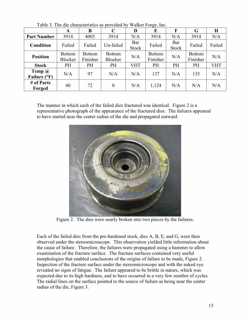
The manner in which each of the failed dies fractured was identical. Figure 2 is a representative photograph of the appearance of the fractured dies. The failures appeared to have started near the center radius of the die and propagated outward.
Figure 2. The dies were nearly broken into two pieces by the failures.
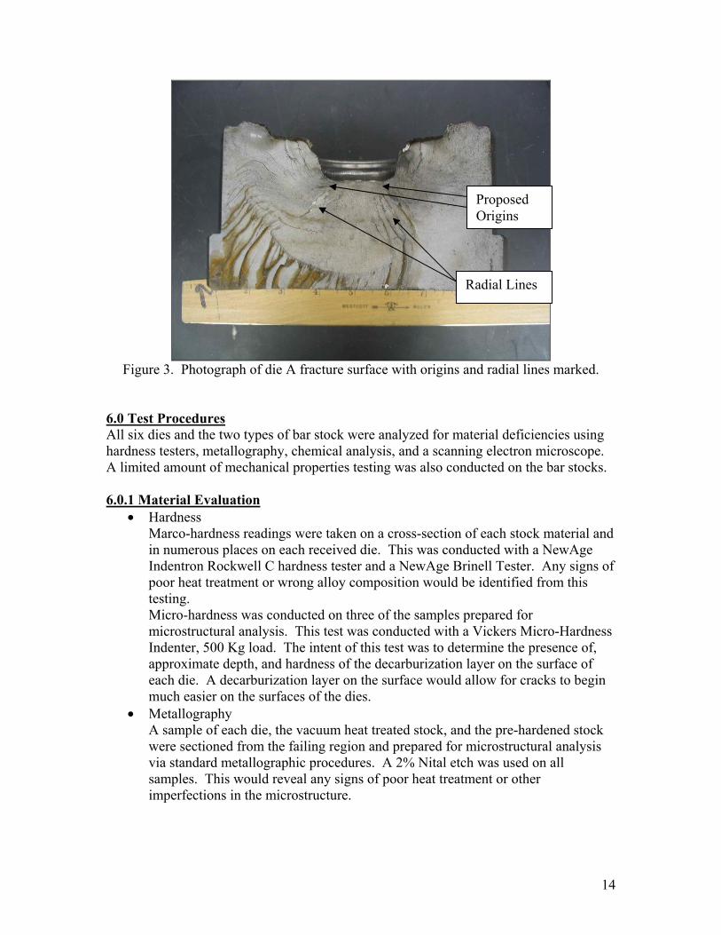
Each of the failed dies from the pre-hardened stock, dies A, B, E, and G, were then observed under the stereomicroscope. This observation yielded little information about the cause of failure. Therefore, the failures were propagated using a hammer to allow examination of the fracture surface. The fracture surfaces contained very useful morphologies that enabled conclusions of the origins of failure to be made, Figure 2. Inspection of the fracture surface under the stereomicroscope and with the naked eye revealed no signs of fatigue. The failure appeared to be brittle in nature, which was expected due to its high hardness, and to have occurred in a very few number of cycles. The radial lines on the surface pointed to the source of failure as being near the center radius of the die, Figure 3.
14
Figure 3. Photograph of die A fracture surface with origins and radial lines marked.
6.0 Test Procedures All six dies and the two types of bar stock were analyzed for material deficiencies using hardness testers, metallography, chemical analysis, and a scanning electron microscope. A limited amount of mechanical properties testing was also conducted on the bar stocks. 6.0.1 Material Evaluation
• Hardness Marco-hardness readings were taken on a cross-section of each stock material and in numerous places on each received die. This was conducted with a NewAge Indentron Rockwell C hardness tester and a NewAge Brinell Tester. Any signs of poor heat treatment or wrong alloy composition would be identified from this testing. Micro-hardness was conducted on three of the samples prepared for microstructural analysis. This test was conducted with a Vickers Micro-Hardness Indenter, 500 Kg load. The intent of this test was to determine the presence of, approximate depth, and hardness of the decarburization layer on the surface of each die. A decarburization layer on the surface would allow for cracks to begin much easier on the surfaces of the dies.
• Metallography A sample of each die, the vacuum heat treated stock, and the pre-hardened stock were sectioned from the failing region and prepared for microstructural analysis via standard metallographic procedures. A 2% Nital etch was used on all samples. This would reveal any signs of poor heat treatment or other imperfections in the microstructure.
Radial Lines
Proposed Origins

15
• Chemical Analysis To ensure that all samples met the manufacturer’s requirement of a H13 tool steel alloy, sections were sent to an outside laboratory (Sherry Laboratories) for chemical analysis. The laboratory used optical emissions spectrometry to determine the alloy composition of manganese, phosphorus, silicon, nickel, chromium, molybdenum, copper, and vanadium. A combustion method was used with a Carbon- Sulfur Leco instrument to determine the carbon and sulfur contents of the steel. Finally an inert gas fusion method on a Leco machine was utilized to determine the percent oxygen of the steel.
6.0.2 Fracture Surface Analysis
• SEM The fracture surfaces of dies A and E were further characterized using a Scanning Electron Microscope (SEM). The samples were first ultrasonically cleaned and then placed in the SEM for observation. The samples were observed both using 20 keV and in a low voltage mode to allow for optimum imaging of the samples.
6.0.3 Machining Defects
• Inspection for cracking The un-failed die, die C, was inspected for cracking in the machined groove where the other die failures had originated. A three-part liquid dye penetrant kit was used for this inspection. The procedure first involves cleaning the sample surface thoroughly with a solvent. Second, the area of interest is masked to minimize dye spreading to irrelevant areas. The dye is then liberally applied to the area of interest and let sit for a minimum of 30 minutes. Third, the dye is wiped thoroughly from all surfaces using a cloth dampened with solvent. Lastly, a developer is applied to the area of interest. The developer will pull the dye out of any notch, crevice, crack, etc. and produce an indication of the defect. To verify the dye penetrant results, die C was also sectioned through the areas of possible cracks. A profile of the possible cracks was then prepared metallographically and observed under a light microscope at various magnifications.
6.0.4 Fracture Toughness Analysis • Mechanical Properties
Fracture toughness tests were performed according to ASTM E1820 on the two types of bar stock, 41-44 HRC vacuum heat treated and 44-46 HRC pre-hardened stock. The range of hardness in the materials allowed for a comparison to fracture toughness values in the ASM Handbook (Volume 1: Properties and Selection: Irons and Steels). This test was conducted with the hypothesis that when the harder materials are machined, cracks are initiated. Also that the harder material has less resistance to crack propagation.
16
7.0 Results and Discussion
7.0.1 Material Evaluation The specified hardness, as determined by Walker Forge, Inc., of the pre-hardened stock dies is 43 – 47 HRC. All of the samples tested were within this range. Testing on the vacuum heat treated stock sample and failed die showed hardness values of approximately 41-44 HRC. Table 4 shows there is little difference in hardness between all of the samples Therefore, the cause of failure does not appear to lie within heat treating problems.
Table 4. Macro-hardness results met specifications. Sample Specification (HRC) HRC (+/-1) BHN
A 43-47 46 415-429 B 43-47 45 415-429 C 43-47 44.5 415-429
D (VHT stock) 41-44 41 401-415 E 43-47 44.9 415-429
F (PH stock) 43-47 47 429-444 G 43-47 45 415-429
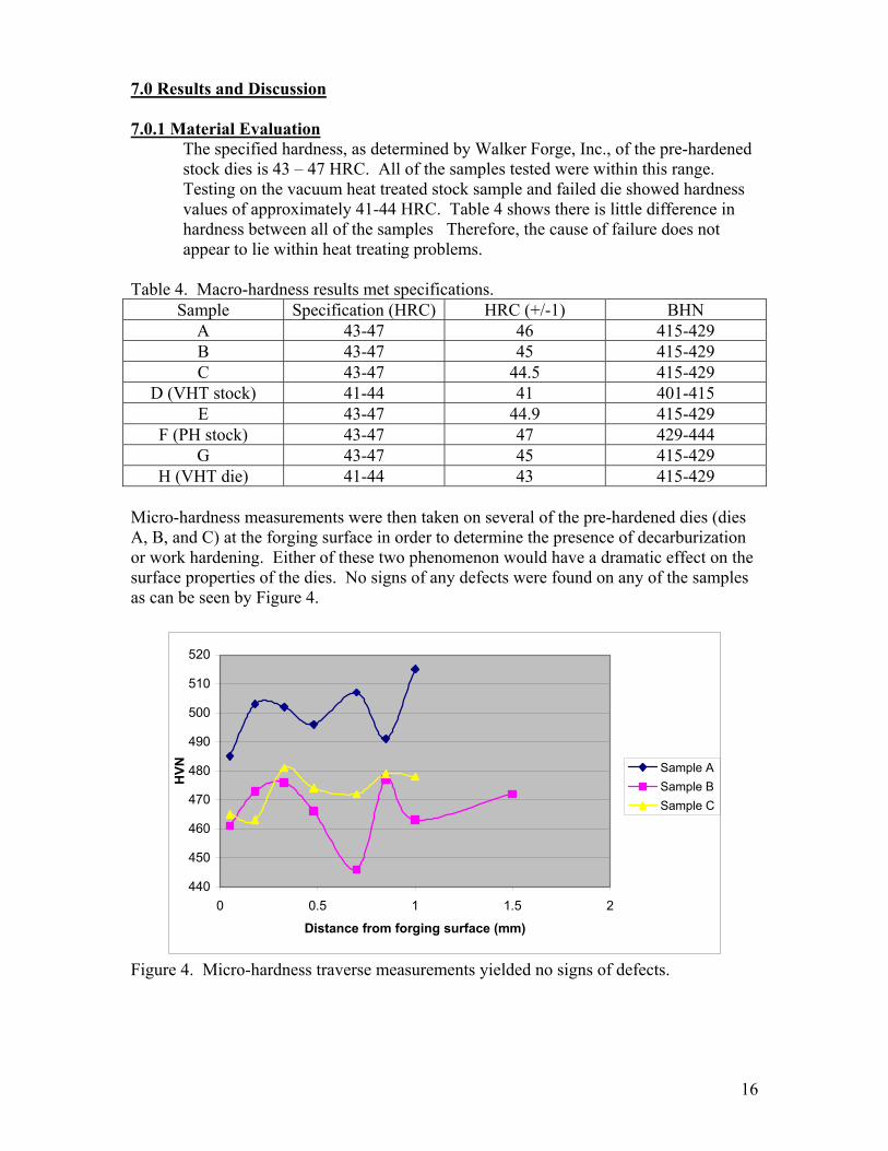
H (VHT die) 41-44 43 415-429 Micro-hardness measurements were then taken on several of the pre-hardened dies (dies A, B, and C) at the forging surface in order to determine the presence of decarburization or work hardening. Either of these two phenomenon would have a dramatic effect on the surface properties of the dies. No signs of any defects were found on any of the samples as can be seen by Figure 4.
440
450
460
470
480
490
500
510
520
0 0.5 1 1.5 2
Distance from forging surface (mm)
HVN Sample A
Sample BSample C
Figure 4. Micro-hardness traverse measurements yielded no signs of defects.
17
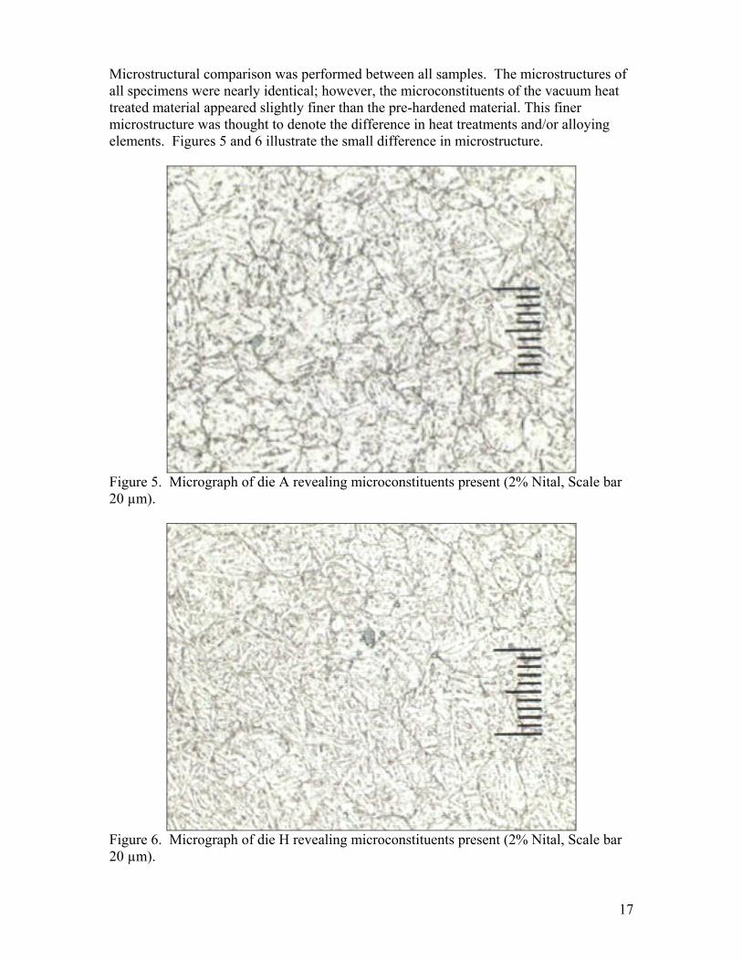
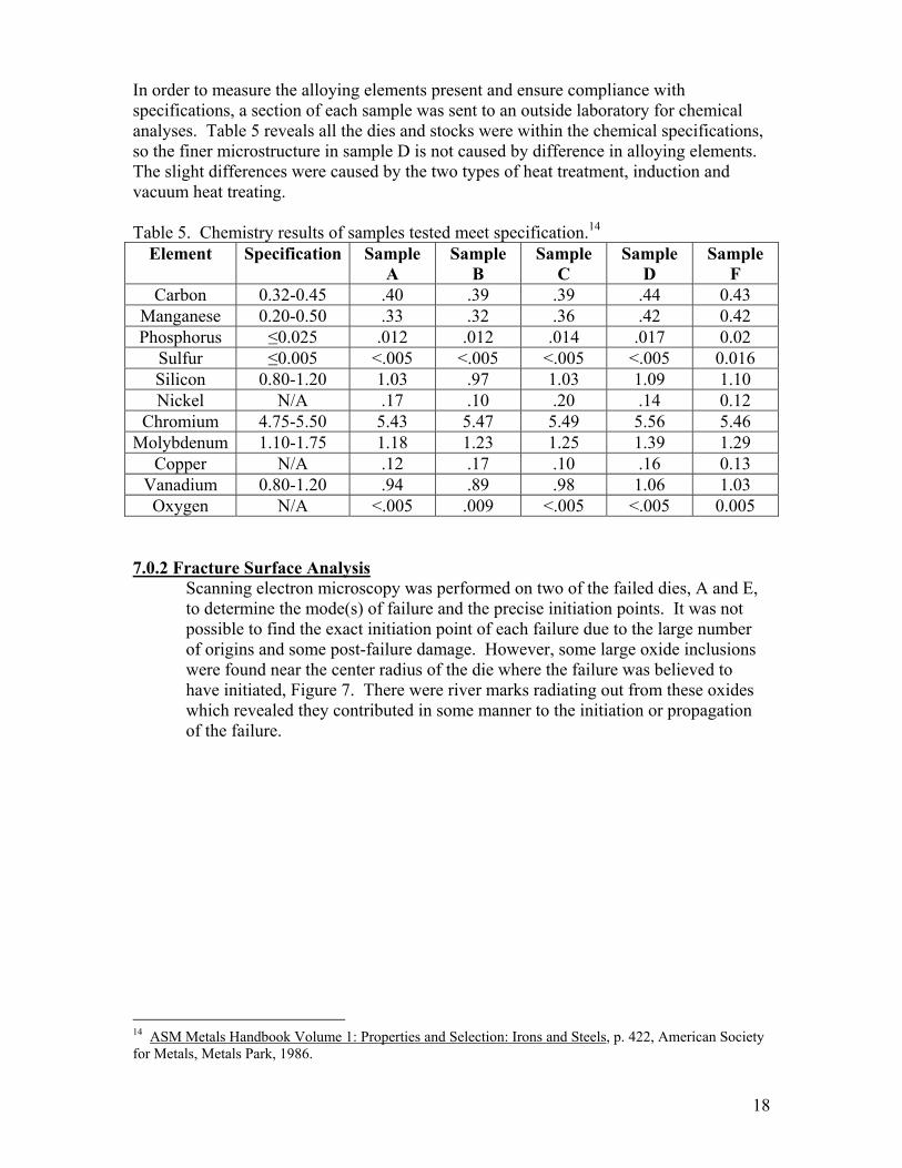
Microstructural comparison was performed between all samples. The microstructures of all specimens were nearly identical; however, the microconstituents of the vacuum heat treated material appeared slightly finer than the pre-hardened material. This finer microstructure was thought to denote the difference in heat treatments and/or alloying elements. Figures 5 and 6 illustrate the small difference in microstructure.
Figure 5. Micrograph of die A revealing microconstituents present (2% Nital, Scale bar 20 µm).
Figure 6. Micrograph of die H revealing microconstituents present (2% Nital, Scale bar 20 µm).
18
In order to measure the alloying elements present and ensure compliance with specifications, a section of each sample was sent to an outside laboratory for chemical analyses. Table 5 reveals all the dies and stocks were within the chemical specifications, so the finer microstructure in sample D is not caused by difference in alloying elements. The slight differences were caused by the two types of heat treatment, induction and vacuum heat treating. Table 5. Chemistry results of samples tested meet specification.14
Element Specification Sample A
Sample B
Sample C
Sample D
Sample F
Carbon 0.32-0.45 .40 .39 .39 .44 0.43 Manganese 0.20-0.50 .33 .32 .36 .42 0.42 Phosphorus ≤0.025 .012 .012 .014 .017 0.02
Sulfur ≤0.005 <.005 <.005 <.005 <.005 0.016 Silicon 0.80-1.20 1.03 .97 1.03 1.09 1.10 Nickel N/A .17 .10 .20 .14 0.12
Chromium 4.75-5.50 5.43 5.47 5.49 5.56 5.46 Molybdenum 1.10-1.75 1.18 1.23 1.25 1.39 1.29
Copper N/A .12 .17 .10 .16 0.13 Vanadium 0.80-1.20 .94 .89 .98 1.06 1.03 Oxygen N/A <.005 .009 <.005 <.005 0.005
7.0.2 Fracture Surface Analysis
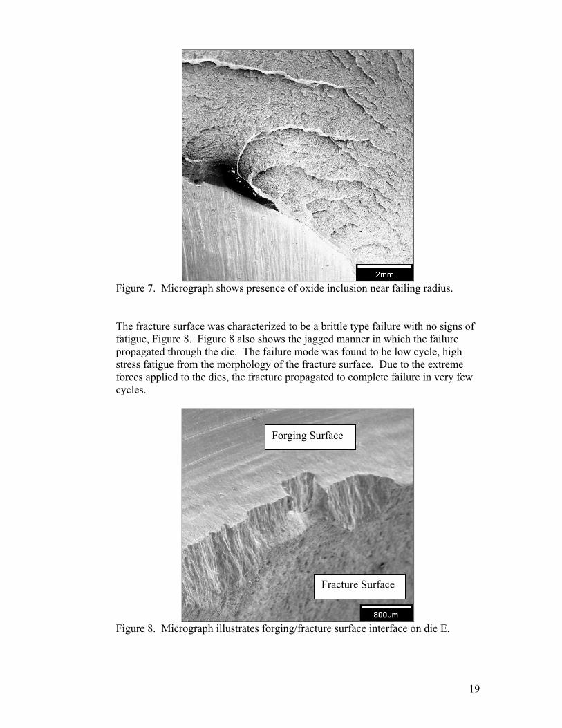
Scanning electron microscopy was performed on two of the failed dies, A and E, to determine the mode(s) of failure and the precise initiation points. It was not possible to find the exact initiation point of each failure due to the large number of origins and some post-failure damage. However, some large oxide inclusions were found near the center radius of the die where the failure was believed to have initiated, Figure 7. There were river marks radiating out from these oxides which revealed they contributed in some manner to the initiation or propagation of the failure.
14 ASM Metals Handbook Volume 1: Properties and Selection: Irons and Steels, p. 422, American Society for Metals, Metals Park, 1986.
19
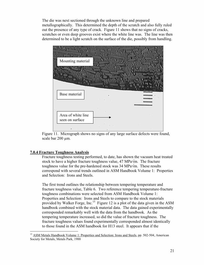
Figure 7. Micrograph shows presence of oxide inclusion near failing radius. The fracture surface was characterized to be a brittle type failure with no signs of fatigue, Figure 8. Figure 8 also shows the jagged manner in which the failure propagated through the die. The failure mode was found to be low cycle, high stress fatigue from the morphology of the fracture surface. Due to the extreme forces applied to the dies, the fracture propagated to complete failure in very few cycles.
Figure 8. Micrograph illustrates forging/fracture surface interface on die E.
Forging Surface
Fracture Surface

20
7.0.3 Machining Defects During SEM observation, the presence of large machining grooves was found near the failing radiuses of the dies.
Figure 10. Stereomicroscopic image shows possible crack.
To find whether or not this or any cracks existed in the die, a dye penetrant test was used. The test revealed no signs of cracks on the machined surface, Figure 11.
Figure 11. Cracks would appear as red lines on the white background.
21
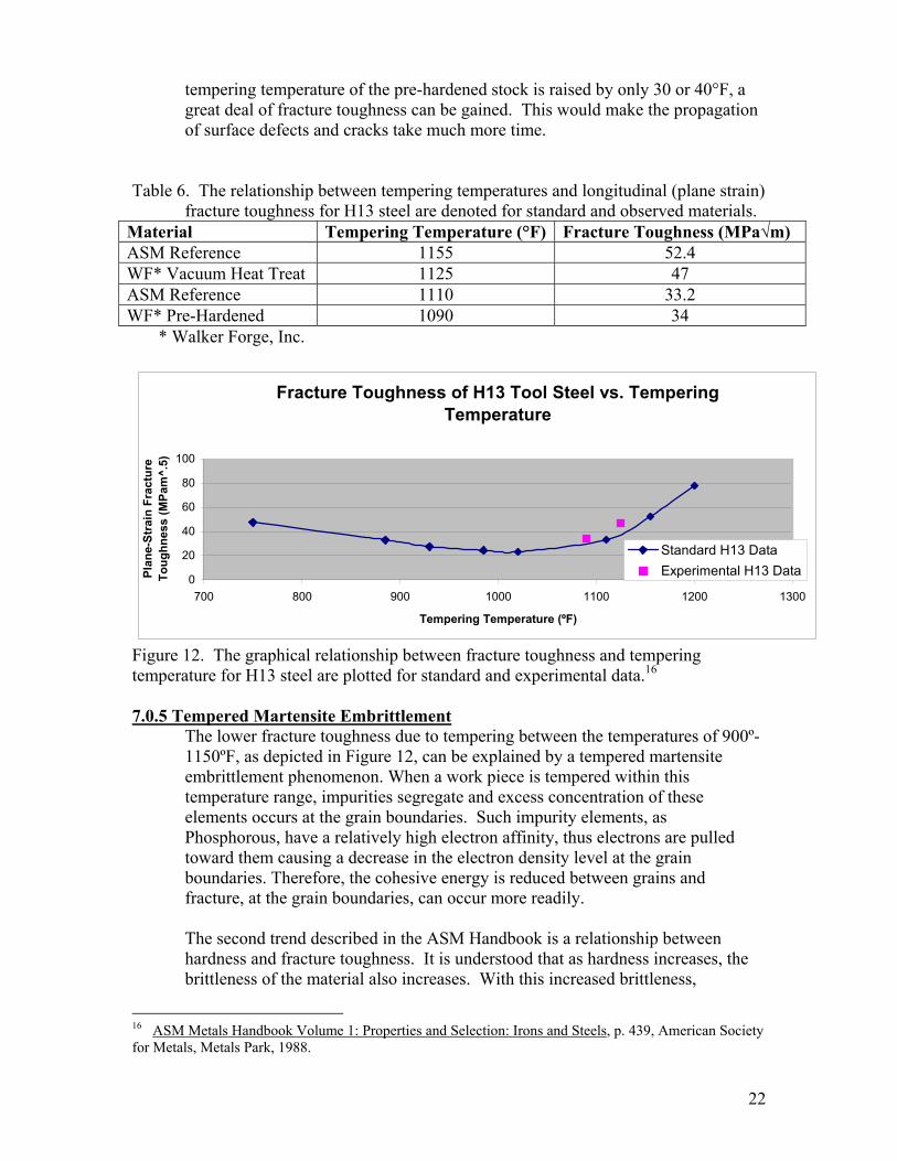
The die was next sectioned through the unknown line and prepared metallographically. This determined the depth of the scratch and also fully ruled out the presence of any type of crack. Figure 11 shows that no signs of cracks, scratches or even deep grooves exist where the white line was. The line was then determined to be a light scratch on the surface of the die, possibly from handling.
Figure 11. Micrograph shows no signs of any large surface defects were found, scale bar 200 µm.
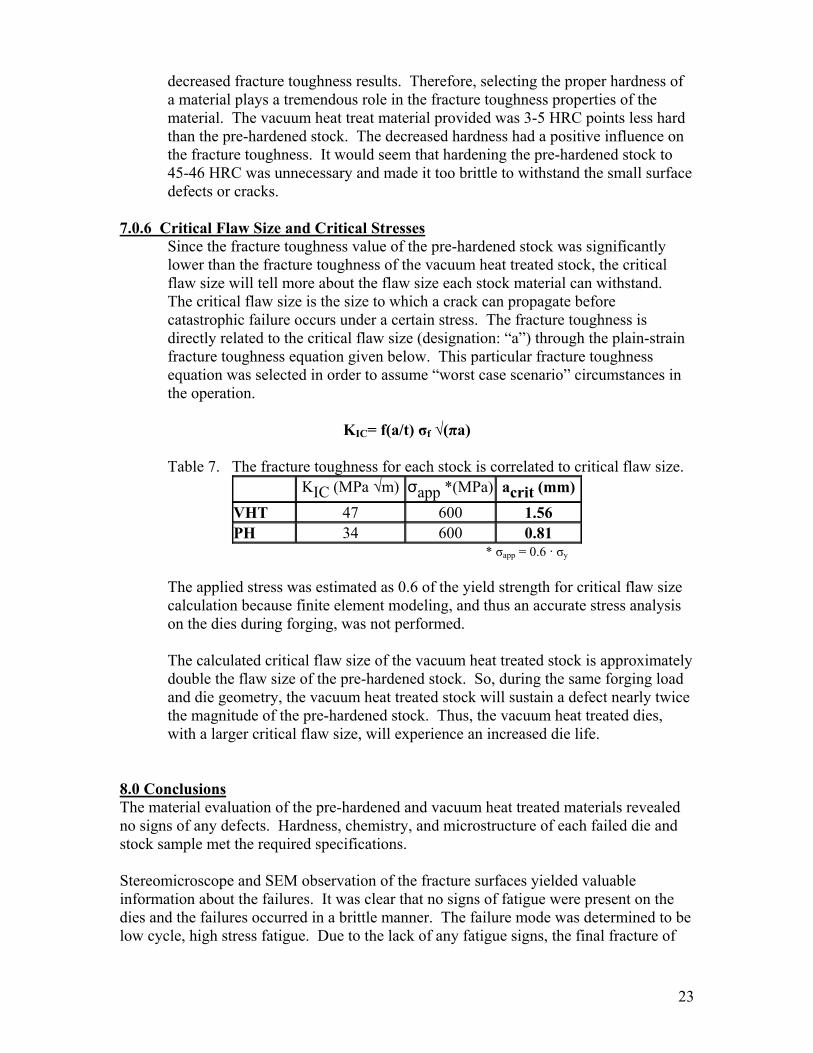
7.0.4 Fracture Toughness Analysis Fracture toughness testing performed, to date, has shown the vacuum heat treated stock to have a higher fracture toughness value, 47 MPa√m. The fracture toughness value for the pre-hardened stock was 34 MPa√m. These results correspond with several trends outlined in ASM Handbook Volume 1: Properties and Selection: Irons and Steels. The first trend outlines the relationship between tempering temperature and fracture toughness value, Table 6. Two reference tempering temperature-fracture toughness combinations were selected from ASM Handbook Volume 1: Properties and Selection: Irons and Steels to compare to the stock materials provided by Walker Forge, Inc.15 Figure 12 is a plot of the data given in the ASM handbook combined with the stock material data. The data gained experimentally corresponded remarkably well with the data from the handbook. As the tempering temperature increased, so did the value of fracture toughness. The fracture toughness values found experimentally corresponded almost identically to those found in the ASM handbook for H13 steel. It appears that if the
15 ASM Metals Handbook Volume 1: Properties and Selection: Irons and Steels, pp. 502-504, American Society for Metals, Metals Park, 1988
Area of white line seen on surface
Mounting material
Base material
22
tempering temperature of the pre-hardened stock is raised by only 30 or 40°F, a great deal of fracture toughness can be gained. This would make the propagation of surface defects and cracks take much more time.
Table 6. The relationship between tempering temperatures and longitudinal (plane strain) fracture toughness for H13 steel are denoted for standard and observed materials.
Material Tempering Temperature (°F) Fracture Toughness (MPa√m) ASM Reference 1155 52.4 WF* Vacuum Heat Treat 1125 47 ASM Reference 1110 33.2 WF* Pre-Hardened 1090 34
* Walker Forge, Inc.
Fracture Toughness of H13 Tool Steel vs. Tempering Temperature
0
20
40
60
80
100
700 800 900 1000 1100 1200 1300
Tempering Temperature (ºF)
Plan
e-St
rain
Fra
ctur
e To
ughn
ess
(MPa
m^.
5)
Standard H13 DataExperimental H13 Data
Figure 12. The graphical relationship between fracture toughness and tempering temperature for H13 steel are plotted for standard and experimental data.16 7.0.5 Tempered Martensite Embrittlement
The lower fracture toughness due to tempering between the temperatures of 900º-1150ºF, as depicted in Figure 12, can be explained by a tempered martensite embrittlement phenomenon. When a work piece is tempered within this temperature range, impurities segregate and excess concentration of these elements occurs at the grain boundaries. Such impurity elements, as Phosphorous, have a relatively high electron affinity, thus electrons are pulled toward them causing a decrease in the electron density level at the grain boundaries. Therefore, the cohesive energy is reduced between grains and fracture, at the grain boundaries, can occur more readily.
The second trend described in the ASM Handbook is a relationship between hardness and fracture toughness. It is understood that as hardness increases, the brittleness of the material also increases. With this increased brittleness,
16 ASM Metals Handbook Volume 1: Properties and Selection: Irons and Steels, p. 439, American Society for Metals, Metals Park, 1988.
23
decreased fracture toughness results. Therefore, selecting the proper hardness of a material plays a tremendous role in the fracture toughness properties of the material. The vacuum heat treat material provided was 3-5 HRC points less hard than the pre-hardened stock. The decreased hardness had a positive influence on the fracture toughness. It would seem that hardening the pre-hardened stock to 45-46 HRC was unnecessary and made it too brittle to withstand the small surface defects or cracks.
7.0.6 Critical Flaw Size and Critical Stresses Since the fracture toughness value of the pre-hardened stock was significantly lower than the fracture toughness of the vacuum heat treated stock, the critical flaw size will tell more about the flaw size each stock material can withstand. The critical flaw size is the size to which a crack can propagate before catastrophic failure occurs under a certain stress. The fracture toughness is directly related to the critical flaw size (designation: “a”) through the plain-strain fracture toughness equation given below. This particular fracture toughness equation was selected in order to assume “worst case scenario” circumstances in the operation.
KIC= f(a/t) σf √(πa)
Table 7. The fracture toughness for each stock is correlated to critical flaw size.
KIC (MPa √m) σapp *(MPa) acrit (mm) VHT 47 600 1.56 PH 34 600 0.81
* σapp = 0.6 · σy
The applied stress was estimated as 0.6 of the yield strength for critical flaw size calculation because finite element modeling, and thus an accurate stress analysis on the dies during forging, was not performed.
The calculated critical flaw size of the vacuum heat treated stock is approximately double the flaw size of the pre-hardened stock. So, during the same forging load and die geometry, the vacuum heat treated stock will sustain a defect nearly twice the magnitude of the pre-hardened stock. Thus, the vacuum heat treated dies, with a larger critical flaw size, will experience an increased die life.
8.0 Conclusions The material evaluation of the pre-hardened and vacuum heat treated materials revealed no signs of any defects. Hardness, chemistry, and microstructure of each failed die and stock sample met the required specifications. Stereomicroscope and SEM observation of the fracture surfaces yielded valuable information about the failures. It was clear that no signs of fatigue were present on the dies and the failures occurred in a brittle manner. The failure mode was determined to be low cycle, high stress fatigue. Due to the lack of any fatigue signs, the final fracture of
24
the die occurred in very few cycles. Since the forces the dies are subjected to are so great, this came as no surprise. Oxide inclusions were found at the failing radius of the dies; however, they could not be pinpointed as the exact origins of failure. Investigation into possible surface defects induced during the machining operation revealed no such defects. The use of dye penetrant and sectioning through the failing radius showed that no cracks or deep machining grooves existed. Current fracture toughness testing has shown the vacuum heat treated stock to have a greater value than the pre-hardened stock. This is a critical result due to the importance of fracture toughness in a forging operation. Indentations and wear are commonalities to dies in forging operations. The greater fracture toughness precludes more resistance to the propagation of these defects. With a larger fracture toughness value, a material is able to withstand a greater force without a crack propagating to failure. 9.0 Recommendations During SEM observation, oxide inclusions were found at the failing radius. It is not known if these were the sole cause of failure. However, the size, quantity, and distribution of the inclusions should be closely monitored to ensure them from becoming problematic. The hardness of the pre-hardened stock was consistently 3-5 HRC points higher than the vacuum heat treated stock. This difference is believed to be a large contributor to the reduced fracture toughness of the pre-hardened stock. Therefore, the hardness of the pre-hardened stock should be lowered to the same range as the vacuum heat treated material to gain valuable fracture toughness properties. The tempering temperature of the vacuum heat treated stock was found to be slightly higher than the pre-hardened stock. This also has an effect on the fracture toughness of the material. The tempering temperature of the pre-hardened stock should be increased to the same level or greater than the vacuum heat treated material. If the tempering temperatures of both stock materials were raised, premature failure of either type of dies may be significantly reduced. If the lower hardness values, as a result of lower the tempering temperature, is not acceptable, surface treating, such as nitriding or carburizing, may extend die life.

25
10.0 References
1. ASM Handbook Volume 14: Forming and Forging, p. 6, American Society for Metals, Metals Park, 1986.
2. Wright, R. N., Study of Premium H13 for Improved Toughness and Temperature
Resistance, Rensselaer Polytechnic Institute (New York), 2003. (www.forging.org/FIERF/pdf/H-13.pdf)
3. H13 Steel Acceptance and Heat Treatment Acceptance Criteria, p. 4, North America
Die Casting Association, 2003.
4. H13 Steel Acceptance and Heat Treatment Acceptance Criteria, p. 2, North America Die Casting Association, 2003.
5. Wilson, R., Metallurgy and Heat Treatment of Tool Steels, p. 146, McGraw-Hill,
London, 1975.
6. Tool Steels, 3rd Edition, p. 546, American Society for Metals, Metals Park, 1971.
7. H13 Steel Acceptance and Heat Treatment Acceptance Criteria, North America Die Casting Association, p. 2, 2003.
8. Properties Profile: Comparison of Premium Quality H13 & Modified Hot Work Die
Steel, p. 41, Die Casting Engineer, May 2002.
9. Wright, R. N., Study of Premium H13 for Improved Toughness and Temperature Resistance, Rensselaer Polytechnic Institute (New York), 2003. (www.forging.org/FIERF/pdf/H-13.pdf)
10. Wright, R. N., Study of Premium H13 for Improved Toughness and Temperature
Resistance, Rensselaer Polytechnic Institute (New York), 2003. (www.forging.org/FIERF/pdf/H-13.pdf)
11. ASM Metals Handbook Volume 10: Failure Analysis and Prevention, p. 500,
American Society for Metals, Metals Park, 1986.
12. Tool Steels, 3rd Edition, p. 545, American Society for Metals, Metals Park, 1971.
13. ASM Metals Handbook Volume 5: Forging and Casting, p. 30, American Society for Metals, Metals Park, 1986.
14. ASM Metals Handbook Volume 1: Properties and Selection: Irons and Steels, p.
422, American Society for Metals, Metals Park, 1986. 15. ASM Metals Handbook Volume 10: Failure Analysis and Prevention, pp. 502-504,
American Society for Metals, Metals Park, 1986. 16. ASM Metals Handbook Volume 1: Properties and Selection: Irons and Steels, p.
439, American Society for Metals, Metals Park, 1988.