failure characterisation of ti6al4v gas turbine · pdf filefailure characterisation of ti6al4v...
TRANSCRIPT

Failure characterisation of Ti6Al4V gas turbine compressor blades
A. Kermanpur1, H. Sepehri Amin1, S. Ziaei Rad2, N. Nourbakhshnia2 & M. Mosaddeghfar3
1Department of Materials Engineering, Isfahan University of Technology, Isfahan 84156, Iran 2Department of Mechanical Engineering, Isfahan University of Technology, Isfahan 84156, Iran 3Isfahan Regional Electric Company, Isfahan, Iran
Abstract
In this study, the failure process of Titanium compressor blades of an industrial gas turbine was investigated. Several premature failures occurred in the high-pressure section of the compressor due to the fracture of the blade roots. Macro- and micro-fractographic investigations were carried out on the fracture surfaces. Optical and scanning electron microscopy of the blade airfoil and root were also performed. Mechanical properties of the blade alloy were evaluated and compared with the standard specifications. Next, a 2D finite element model of the blade root was constructed and used to provide accurate estimates of stress field in the dovetail blade root and to determine the crack growth initiation in the dovetail. Based on the normal service operation of the compressor, the centrifugal and shear forces applied to the blade-disc configuration were considered in the model. The experimental results showed no metallurgical and mechanical defects for the blade materials. Microstructure of the blade root and airfoil, and hardness and tensile properties were all comparable with those reported in the standard specification. Fractography experiments clearly showed multiple crack initiation sites and fatigue beach marks. Debris particles were observed on the fracture surfaces and in the mouth of initiated cracks. The blade surface in contact with the disc in the dovetail region showed a higher surface roughness than the other surfaces. The numerical model clearly showed stress concentration at the corner on the contact facet of the blade dovetail between the blade dovetail and the wheel dovetail. Based on the results obtained, the fretting fatigue mechanism was proposed for the premature failures. Keywords: fretting fatigue, compressor blade, fractography, finite element method, computer simulation.
© 2007 WIT PressWIT Transactions on Engineering Sciences, Vol 57, www.witpress.com, ISSN 1743-3533 (on-line) doi:10.2495/MC070381
Computational Methods and Experiments in Materials Characterisation III 383

1 Introduction
The phenomenon of ‘fretting fatigue’ has been recognized and studied well for over a century. Fretting is defined as the wear process occurring between two surfaces that have an oscillatory motion of small amplitude, on the order of tens of microns [1]. It has been responsible for a large number of service failures across a wide range of applications. For example, fretting in railway axles was reported by Maxwell et al. [2] in 1967, yet remains a cause for concern in forty years later [3]. For obvious reasons, fretting fatigue is particularly important in safety-critical industries such as aerospace or nuclear power generation. The recent High Cycle Fatigue (HCF) initiative [4] in the USA has provided a focus for fretting research in the aerospace sector, particularly in aircraft engine applications. These include the ‘dovetail’ roots of compressor blades (Nowell, [5]), where failure may have serious consequences for engine integrity (Xi et al., [6]). Furthermore, wherever two or more turbine components are in tight contact, fretting fatigue becomes a relevant failure mechanism. Yoshimura et al. [7] evaluated the fretting fatigue life of titanium alloy dovetails by using stress singularity parameters. They also used the finite element method to show that there exists stress concentration and high stress gradient in the zone of crack initiation under work condition. Arrieta and his co-workers [8] focused on identifying the driving factors for fretting damage on blade-disk attachment under real engine conditions. Two-dimensional finite element contact calculations were carried out to quantify the influence of the key factors on mechanical quantities such as stress and strain. Special attention was paid to material models and surface interaction (friction coefficient and contact conditions) in order to balance computational effort with result’s accuracy. Nowell [9] reviewed a number of recent developments, starting with attempts to apply multi-axial initiation criteria to the fretting problem. The importance of the size effect was highlighted and an analogy was made between fretting and notch fatigue. Methods for characterising crack initiation using asymptotic analysis were discussed, together with short crack arrest concepts which provide a means of predicting fretting fatigue limits from plain fatigue data. Golden and Calcaterra [10] evaluated a fracture mechanics based crack growth life prediction methodology for dovetail fretting fatigue laboratory experiments. They considered contact loads and bulk stress calculated from finite element method as input to the stress and life estimation analysis. Their analysis showed that propagation consumes a majority of the total life and was investigated to a large range of initial crack sizes. In this paper, several premature failures of Ti alloy compressor blades were characterised by both experimental observations and 2D finite element modelling. Characteristics of the fretting fatigue mechanism are also discussed.
2 Materials and procedures 2.1 Experimental Several premature failures were occurred in the high pressure compressor of gas turbines of Hesa power plant due to the fracture of the blade roots. The plant is
© 2007 WIT PressWIT Transactions on Engineering Sciences, Vol 57, www.witpress.com, ISSN 1743-3533 (on-line)
384 Computational Methods and Experiments in Materials Characterisation III

working under nominal output power 29MW with the rotating speed 8500rpm in the high pressure compressor. The failures were experienced at the 9th, 10th, and 12th stages of the compressor. Table 1 lists only the working history of the fractured blades in the 9th stage. First, chemical composition and mechanical and metallurgical properties of the blades were characterised. In order to perform optical microstructural investigations, metallographic tests were carried on different samples prepared from the root and airfoil of blades. Hardness test on the root and airfoil of the blades was performed using Hauser 292DR machine. Tensile test was carried on the sub-sized specimens, which were prepared from root of blades according to JIS-Z 2201 standard by Instron-8500 machine. Macro-fractography was performed on the surface of the samples by digital camera. In one of the fracture occurrences, a blade was left inside the disc with a crack in the root region. The fracture surface of the blade was also investigated along with the other completely fractured blades. Micro-fractography studies were carried out on all the failed samples by SEM Philips X230 machine equipped with EDS chemical analysis.
Table 1: Working history of the failed blades of stage 9.
Number Date Working hours 1 March 2005 7653 2 May 2005 7669
2.2 Simulation
Figure 1 shows a schematic of the forces acting on the blade-disc configuration. The simulation was carried out in two phases. First, a fluid analysis was carried out to estimate the aerodynamic force exerted on the blade. Then, the calculated aerodynamic forces together with the centrifugal force were used to obtain the stress analysis and to determine the stress concentration in the contact regions.
Figure 1: The forces acting on the rotating blade.
Aerodynamic force Centrifugal force
Contact force
© 2007 WIT PressWIT Transactions on Engineering Sciences, Vol 57, www.witpress.com, ISSN 1743-3533 (on-line)
Computational Methods and Experiments in Materials Characterisation III 385

2.2.1 Fluid flow calculations A 2D fluid flow analysis was performed to estimate the forces acting on the blade under steady-state work condition. Simulation was made using the commercial software FLUENT. One static vane and one rotating blade were considered in the model. In the fluid calculation, the vane movement was assumed to be zero. The blade velocity was set to be rω, where ω is the compressor rotating speed and r is the average distance of the blade from the disk centre. The fluid was assumed compressible and viscose. The k-ε equation was used to model the turbulence.
2.2.2 Stress calculations A 2D finite element analysis was conducted to evaluate stress concentration in the system. To apply the centrifugal force, the origin of coordinate system was located at the disk centre, and an angular velocity of 8500 rpm was applied to the disk-blade structure. The dovetail region was modelled using the finite element software ANSYS. Figure 2a shows the meshing created on the blade and disk. The mesh consisted of 525 2D plane stress four-node elements as well as 169 surface-to-surface contact elements. A close-up of the mesh near the interface between contact surfaces is shown in Figure 2b. The disc material was made of steel and the blade material was Ti-6%V-4%Al. All the centrifugal, contact and aerodynamic forces were considered in the model.
Figure 2: a) Finite element model of the blade and a part of disc in the dovetail region; b) Details of the mesh in the contact area.
3 Results and discussion
3.1 Experimental results
Table 2 shows chemical composition of the blade material compared with the standard limits of Ti6Al4V alloy. It confirms that the composition of the fractured blade is in fact Ti6Al4V alloy. The microstructures of the blade root
386 Computational Methods and Experiments in Materials Characterisation III

and airfoil with different work hours are presented in Figure 3. It is consisted of predominantly equiaxed α grains, lamellar transformed α plates, and fine intergranular β phases. It should be noticed that this microstructure is common in Ti-alloy compressor and fan blades, with equiaxed portion providing good tensile ductility and hence good resistance to crack initiation, while the lamellar portion is responsible for increasing resistance to crack propagation.
Table 2: Chemical composition of the blading alloy.
Composition Al V Fe Zr Mn Mo Sn Nb Pd Ti
min 5.50 3.50 --- --- --- --- --- --- --- Standard max 6.75 4.50 0.30 --- --- --- --- --- ---
Rem
Mean 5.18 3.91 0.15 <0.10 <0.10 <0.50 <0.50 <0.50 0.19 88.16 Blade RSD 1.95 1.31 17.9 --- --- --- --- --- 0.74 0.08
a b
c d
Figure 3: Microstructure of the fractured blades: a,b) root & c,d) airfoil; a,c) 1st & b,d) 2nd fractures.
Table 3: Vickers hardness of the blade’s root and airfoil.
Number Position HV Airfoil 359.33 1st fracture Root 335.8
Airfoil 353.25 2nd fracture Root 338.17
Hardness values of the root and airfoil of two failed blades are presented in Table 3. The root and airfoil both had the same hardness. Tensile properties of the samples with different work hours are shown in Table 4. It can be seen that the mechanical and metallurgical properties of the blade material are in the standard range and no deviation in these properties were detected.
© 2007 WIT PressWIT Transactions on Engineering Sciences, Vol 57, www.witpress.com, ISSN 1743-3533 (on-line)
Computational Methods and Experiments in Materials Characterisation III 387

Table 4: Mechanical properties of different fractured blades.
Sample YS [MPa]
UTS [MPa]
Elongation [%]
Reduction of Area [%]
Standard (min) 862 931 10 25 1st fracture 961 1093 11.8 39.2 2nd fracture 984 1025 16 33
Figure 4: Fracture surfaces of the: a) 1st and b) 2nd failure. Note that three distinct regions are numbered and the main position for crack initiation are identified by an arrow.
Figure 4 shows macro-fractography images of the 1st and the 2nd failures. Three different regions are remarkable in each fracture surface. In the first and second regions, beach marks are clearly detectable. Moreover, several radial lines can be revealed in each fracture surface. The position of the main crack initiation from the front edge of contact (EOC) of both blades are shown (Figure 4). It is seen that the characteristics of the fracture surfaces and the position of crack initiation are more or less similar for both failures. Micro-fractography tests were performed on different fracture surfaces as shown in Figure 5 for the 1st fracture. Figure 5a shows the main crack, beach marks and radial lines in region 1 of fracture surface. Figure 5b illustrates the fatigue appearance in region 2. The image of EOC and multiple micro crack initiation are observed in Figure 5c. The brittle fracture mode can be clearly seen in the fracture surface as shown in Figure 5d. Many debris particles as an indication of wear were found on EOC and in the mouth of cracks (Figure 6). EDS analysis (Table 5) of the debris particles showed a high amount of oxygen confirming oxidation of Ti during the service, which is responsible to form abrasive TiO2 particles in the fracture surface. Debris also shows some Fe content coming from the steel disk. Sever sliding and rough surfaces were observed in EOC in the blade roots as shown in Figure 7. It is believed that the coating of blade root and disk in the contact region were damaged making these surfaces so rough which can directly influence the crack initiation. The results of roughness measurements are listed in Table 6. As it can be seen, the maximum surface roughness is achieved in the EOC region.
© 2007 WIT PressWIT Transactions on Engineering Sciences, Vol 57, www.witpress.com, ISSN 1743-3533 (on-line)
388 Computational Methods and Experiments in Materials Characterisation III

(a)
(c) (d)
(b)
Figure 5: Micro-fractography of the 1st fracture surface: a) region 1, b) transition to region 2, c) EOC, and d) brittle manner of material.
Table 5: EDS analysis of the blade alloy and debris on EOC.
Location Ti Al Si V Fe Mo Na P O Matrix 89.39 7.75 0.25 2.61 --- 1.18 --- --- --- Debris 32.24 5.89 2.43 1.52 2.42 1.18 0.48 0.4 52.8
According to all experimental results, existence of multiple crack initiation at EOC, presence of debris in the contact region, severe sliding wear, and high roughness at EOC, proposed that the main reason for failure phenomenon in the premature fractures of Ti alloy blades is the fretting fatigue mechanism.
3.2 Simulation results
The fluid analysis was carried out to estimate the aerodynamic force exerted on the blade. The dynamic and static pressure distributions around the stator vane and the rotor blade were evaluated. According to the fluid flow analysis, the
© 2007 WIT PressWIT Transactions on Engineering Sciences, Vol 57, www.witpress.com, ISSN 1743-3533 (on-line)
Computational Methods and Experiments in Materials Characterisation III 389

values of total forces exerted on the rotor by gas (the aerodynamic forces) in x, y and z directions are estimated to be: 0, -858.0 and 509.5 kPa, respectively. These values were used in the stress model as the aerodynamic forces.
Figure 6: Micro-fractography of the 1st cracked blade fracture surface showing the appearance of main crack and compact debris in mouth of crack.
Figure 7: Micro-fractography of the 2nd fracture surface showing sliding marks on EOC.
Table 6: Roughness at different regions of the blade.
Roughness Airfoil (convex side)
Airfoil (Concave side)
Root, no contact
Root, EOC, near crack
Root, EOC
Ram (µm) 0.863 0.950 1.183 2.493 3.770 STDEV 0.09 0.06 0.15 0.94 1.98
© 2007 WIT PressWIT Transactions on Engineering Sciences, Vol 57, www.witpress.com, ISSN 1743-3533 (on-line)
390 Computational Methods and Experiments in Materials Characterisation III
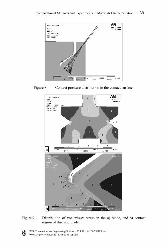
Figure 8: Contact pressure distribution in the contact surface.
a
b
Figure 9: Distribution of von misses stress in the a) blade, and b) contact region of disc and blade.
© 2007 WIT PressWIT Transactions on Engineering Sciences, Vol 57, www.witpress.com, ISSN 1743-3533 (on-line)
Computational Methods and Experiments in Materials Characterisation III 391

In the stress analysis, the centrifugal, contact and aerodynamic forces were applied to the model. Figure 8 indicates the high contact pressure at the EOC between blade dovetail and wheel dovetail. Figure 9 shows the von misses stress distribution and stress concentration in the contact surfaces. It can be seen that the maximum stress of about 195 MPa has achieved in the corner on EOC, the position that is in agreement with the experimental characterisation. It was concluded that this stress concentration has been caused by either unsuitable curvature ratio of the disk dovetail, incorrect design of the blade or tight contact between the blade root and the disk in dovetail region. It seems that the aforementioned factors as well as abnormal vibration have caused the fretting fatigue failure of the 9th stage compressor blades. The simulation model is under development to consider the fatigue feature of the aerodynamic force as well.
4 Conclusions
A fretting fatigue mechanism as the main cause of several premature fractures of Ti alloy compressor blades was characterised. All fretting characteristics were distinguished in the fracture surfaces. The developed 2D numerical model clearly showed that stress concentration is happened at the corner of EOC. The high stress at the dovetail region can be either due to the unsuitable curvature ratio of the disk dovetail, incorrect design of the blade, insufficient distance between the blade root and the disk in dovetail region, or abnormal vibration, causing the fretting fatigue failure of the 9th stage compressor blades which eventually leads to the complete failure of the blade and its separation from the disk.
Acknowledgement
The authors would like to acknowledge Isfahan regional electric company for financial support of this work under contract 100/31911-113.
References
[1] Hutson, A.L. et al., Int. J. Fatigue, 24, pp.1223-34, 2002. [2] Maxwell, W.W. et al., Proc. I. Mech. E, 182, pp.89-108, 1967. [3] Hirakawa, K. et al., Int. J. Fatigue, 20(2), pp.135-144, 1998. [4] Burns, C., Proc. 7th Nat. Turbine Engine HCF Conf., Dayton, Ohio, 2002. [5] Nowell, D., Proc. Prog. in Structural Mechanics, Univ. of Seville, 61,
2000. [6] Xi, N.S. et al., Engineering Failure Analysis, 7(6), pp.385-392, 2000. [7] Yoshimura, T. et al., J. of Mate. Sci. Soc. of Japan, 40(6), pp.41-46, 2003. [8] Arrieta, H.V. et al., H., Technical Report, RTO-MP-AVT-109, 2003. [9] Nowell, D., Recent Developments in the Understanding of Fretting
Fatigue, Department of Engineering Science, University of Oxford, 2004. [10] Golden, P.J. & Calcaterra, J.R., Trib. Int., 39(10), p.1172, 2006. [11] Mazur, Z. et al., Engineering Failure Analysis, 13, p.1338, 2006.
© 2007 WIT PressWIT Transactions on Engineering Sciences, Vol 57, www.witpress.com, ISSN 1743-3533 (on-line)
392 Computational Methods and Experiments in Materials Characterisation III