failure mechanisms of a notched cfrp laminate under multi-axial loading · · 2016-04-261 failure...
TRANSCRIPT

1
Failure mechanisms of a notched CFRP laminate under multi-axial loading
J L Y Tan, V S Deshpande and N A Fleck *,
Cambridge University Engineering Dept., Trumpington St., Cambridge, CB2 1PZ, UK
9 April 2015
* Corresponding author. Tel.: +44 (0)1223 748240; fax: +44 (0)1223 332662.
Email address: [email protected] (N.A. Fleck).
Abstract
A quasi-isotropic CFRP laminate, containing a notch or circular hole, is subjected to combined
tension and shear, or compression. The measured failure strengths of the specimens are used to
construct failure envelopes in stress space. Three competing failure mechanisms are observed, and
for each mechanism splitting within the critical ply reduces the stress concentration from the hole or
notch: (i) a tension-dominated mode, with laminate failure dictated by tensile failure of the 0o plies,
(ii) a shear-dominated mode entailing microbuckling of the -45o plies, and (iii) microbuckling of the
0o plies under remote compression. The net section strength (for all stress states investigated) is
greater for specimens with a notch than a circular hole, and this is associated with greater split
development in the load-bearing plies. The paper contributes to the literature by reporting sub-
critical damage modes and failure envelopes under multi-axial loading for two types of stress raiser.
Keywords. A. Laminates; B. Fracture; Stress concentrations; D. Mechanical testing.
1. Introduction
Carbon fibre/epoxy laminates commonly fail from stress raisers such as holes and notches. Such
stress raisers arise from bolt and rivet holes, access holes for the routing of cables, and so on.
2
Subcritical damage evolves from these stress raisers under increasing remote load until catastrophic
failure ensues. The challenge is to observe the damage mechanisms within each ply and between
plies (e.g. delamination) as a function of stress raiser and stress state of remote loading. The present
study documents the sequence of damage evolution for a quasi-isotropic laminate, and a follow-on
paper [1] attempts to predict this damage evolution and associated failure envelope for multi-axial
loading.
Most previous investigations have been limited to uniaxial loading, see Awerbuch and Madhukar
[2] for an early review on the notched tensile behaviour of composite laminates. Generally, three
main forms of damage can be identified: matrix cracking along the fibre directions (i.e. splitting),
fibre tensile failure and delamination between plies. Splitting and delamination are observed in a
wide range of lay-ups and material systems prior to ultimate failure [3–10], along with fibre fracture
[11–13]. The matrix splitting and delamination reduce the local stress concentration at the notch
tips in the load-bearing 0° plies by redistributing the stress away from the notch, thereby delaying
the onset of catastrophic tensile fracture of the 0° fibres. This crack-blunting effect strengthens the
tensile specimen and accounts for the observation that the tensile strength of the notched laminate
does not scale in inverse proportion to the stress concentration factor 𝑘𝑇, where 𝑘𝑇 is defined here
as the ratio of maximum in-plane stress to the net-section stress [3,8,12].
An extensive literature also exists on the compressive failure of fibre-reinforced composites, see for
example Fleck [14]. He identified six competing mechanisms of compressive failure: elastic
microbuckling, plastic microbuckling, fibre crushing, splitting of the matrix, buckle delamination of
surface layers and shear band formation. Most of these mechanisms are dictated by matrix
properties, which explain why the longitudinal compressive strength of composites is usually
relatively low [14]. Of all the mechanisms of compressive failure in composites, plastic
microbuckling is the most ubiquitous [14–17], and the microbuckling leads to kink bands inclined
at an angle β of 10°-20° to the transverse axis, see for example Soutis et al. [15]. X-ray radiography

3
reveals that 0° fibre microbuckling, delamination (between the off-axis plies and the load-bearing
0° plies) and matrix splitting initiate at notch tips at approximately 80% of the failure load [15,18].
The damage grows stably under increasing remote load to a length of 2-3mm before becoming
unstable and propagating catastrophically across the width of the notched specimen [15,18]. These
damage modes reduce the stress concentration at the edge of the hole/notch and delay the onset of
final failure [18].
In contrast to tensile and compressive loading, experimental investigations into the damage and
failure mechanisms of CFRP laminates in shear have been limited. Purslow [19–21] reported the
characteristic features of shear failure in CFRP laminates by fractographic inspection. Broughton et
al. [22] loaded double, edge-notched unidirectional specimens in shear, and considered two
orientations of fibre:
(i) 0o specimens, such that the notch-plane is transverse to the fibre direction, and
(ii) 90o specimens such that the notch-plane is aligned with the fibre direction.
The 0o specimens underwent splitting of the 0° plies at the notch root thereby relieving the stress
concentration. An additional damage zone advanced from each notch root across the ligament; this
damage comprised interfacial microcracks between fibres and matrix. In contrast, shear loading of
the 90o specimens resulted in catastrophic failure by matrix cracks extending parallel to the fibres
and across the ligament section of the specimen. Jelf and Fleck [23] similarly noted that
unidirectional tubular specimens under torsion failed by splitting along the fibre direction.
Hollmann [24] analysed the shear failure of edge-notched multi-directional composites using the
Iosipescu and double rail shear fixtures along with X-ray radiography. Unidentified damage
developed in the -45° ,45° and 90° plies from the notch root, along with delamination. Hollmann
[25] observed similar damage modes when a CFRP spar web, containing an off-centre semi-

4
symmetric cut-out, was loaded in shear. Vogler and Kyriakides [26] and Totry et al. [27] monitored
the development of damage in CFRP laminates under shear using fractography and optical
microscopy, respectively. Only the damage on the surface of these specimens was observed by the
optical microscopy and thus a complete characterisation of shear damage was not achieved. There
is a clear gap in the literature for the systematic characterisation of progressive shear damage in
notched multi-directional CFRP laminates.
Likewise, few studies have addressed the characterisation of damage in CFRP composites under
combined tension and shear. Wu [28] tested an unidirectional glass fibre/polyester centre-notched
lay-up in combined tension and shear to ascertain if fracture mechanics is applicable to orthotropic
laminates, but did not attempt to investigate the damage progression. Francis et al. [29] restricted
their attention to first ply failure in tubular CFRP specimens subjected to axial tension and torsion.
They found that first ply failure was by matrix shear or by matrix tensile failure. They did not
examine subsequent damage development. Gilchrist and Svensson [30] performed a fractographic
study of delamination in multidirectional laminates under combined tension and shear. Fibre pull-
out was a major feature when tension was dominant and matrix-cusps were the major feature when
shear was dominant. Preliminary attempts to characterise damage and failure in notched CFRP
laminates under combined tension and shear was conducted by Gning et al. [31] and Laffan et
al.[32]. However, Gning et al. [31] limited their study to visual inspection while Laffan et al. [32]
examined the fracture surfaces. Consequently, a characterisation of the mechanisms of damage
evolution in fibre composites for combined tension and shear remains to be addressed.
In summary, the fracture mechanisms of notched CFRP laminates are well-documented for tension
and compression. Equivalent work for shear and for combined tension and shear is lacking. The
present paper aims to address this shortfall. A modified Arcan rig was designed, manufactured and
used to apply pure tension, direct compression, in-plane shear and a range of combined tensile and
shear loading on quasi-isotropic specimens with a central notch. Two geometries were investigated

5
(notch and circular hole) to assess the effect of stress concentration upon fracture behaviour. The
damage and failure mechanisms for each configuration were characterised, and failure envelopes
were constructed in a tension-shear stress space. The results will be used to validate a finite
element model in a subsequent publication [1].
2. Test Method
2.1 Specimen manufacture
Quasi-isotropic panels of stacking sequence [45/0/-45/90]2S were hand laid-up from HexPly®
IM7/8552 carbon-fibre/epoxy (CFRP) pre-preg, and then vacuum-bagged and autoclaved following
the cure cycle of the manufacturer. The as-cured CFRP panels, of thickness B = 2mm, were cut to
the specimen dimension 90mm × 25mm using a water-cooled diamond saw. The specimens were
end-tabbed with 1.0mm thick aluminium sheet using a toughened epoxy adhesive (Spabond 345), to
give a gauge section of length 23mm (and width w = 25mm), see Figure 1. Two notch geometries
were employed:
(i) a hole of diameter 6 mm, machined using a tungsten carbide drill bit, or
(ii) a notch of height b = 0.70mm (root radius 0.35 mm) and length a = 6.25mm. To achieve this, a
linear array of small holes was joined using a fine fretsaw blade. Any minor misalignment from
hole to hole of the array has a negligible influence upon the strength of the specimen1.
The elastic stress concentration factor 𝑘𝑇 for the circular hole is on the order of 3 for tension and 6
for shear loading for the quasi-isotropic lay-up. In contrast, the notch induces a much greater stress
concentration factor of approximately 6 for tension and 10 for shear. These values of 𝑘𝑇 were
calculated by modelling the specimens as finite, linear elastic isotropic plates in plane stress using
1 This has been verified by conducting an elastic stress analysis of the specimen with an irregular notch (of
actual geometry) with that of an idealised notch (no irregularities associated with hand manufacture). The stress
concentration factor and stress state ahead of the notch are identical for both geometries to within numerical
accuracy.

6
the ABAQUS finite element program. We use the definition 𝑘𝑇 = 𝜎𝑚𝑎𝑥/𝜎𝑛𝑒𝑡, where 𝜎𝑚𝑎𝑥 is the
maximum in-plane principal stress due to the stress-raiser and 𝜎𝑛𝑒𝑡 is the net-section stress. The
maximum in-plane principal stress is co-directional with the loading direction for tensile and
compressive loading, and is along the -45° direction in the shear-loaded laminate. We note that the
maximum principal stress is a suitable parameter for defining 𝑘𝑇 as this stress component causes
failure of the critical load-bearing ply, as will be shown later for each observed failure mechanism.
The above values of stress concentration are close to the infinite plate results, suggesting that the
boundaries of the specimen have a minor influence upon the stress state near the stress raiser.
The net-section failure stress was measured for the two specimen geometries under pure tension,
direct compression, in-plane shear, and combined tension and shear2. Additionally, interrupted tests
were performed in order to obtain the ply-by-ply (and inter-ply) progression of sub-critical damage.
The two geometries allow for an assessment of the role of stress concentration upon strength (and
damage mechanism).
2.2 Test method: Modified Arcan rig
A combination of tensile and shear loading (and also direct compression) was achieved using a
modified version of the Arcan test method [33], see Figure 2a. Friction grips rather than pin-
loading were used for load-transfer into the centre-notched specimens; this diffuse mode of loading
ensures that the specimens fail from the notch root and not from stress raisers within the grips. The
modified Arcan rig comprises four identical plates: the specimen is friction-gripped between a front
and back pair. The plates were water-jet cut from 8.0mm thick A.I.S.I Type 01 Ground Flat Stock,
and subsequently hardened to 58 Rockwell C by holding them at 800°C for 1 hour, followed by an
2 Note that the choice of presenting results in terms of net section or gross section stress is
somewhat arbitrary. The advantage of using the measure of net section stress is that the
reader can deduce immediately whether the net section strength criterion is satisfied in the
presence of a stress raiser.

7
oil-quench and temper at 200°C for 3 hours. These plates were sufficiently thick to behave in an
essentially rigid manner during each test.
The specimens were gripped to the modified Arcan rig using eight M8 bolts, with each bolt torqued
at 5Nm intervals to 20Nm. This ensured that an uniform clamping pressure was applied to the
specimen tabs. Care was taken to ensure good specimen alignment to give symmetric loading. The
assembly was then pin-loaded by a screw-driven tensile testing machine and the specimens were
tested quasi-statically (displacement rate = 0.01 mm s-1) in tension, shear, combined tension and
shear, and in compression by varying the loading angle φ, as defined in Figure 2a. Figure 2b shows
a photograph of a typical experimental set-up for the modified Arcan rig assembly; in this case for
shear testing. The modified Arcan rig is capable of applying loads at loading angle intervals of 15°.
When φ equals 0°, the loading is tension or compression depending upon the loading direction.
When φ equals 90°, the loading is simple shear. An intermediate angle φ between 0° and 90° gives
tension and shear. If the applied load is 𝑃, then the tensile component of load equals 𝑃 cos 𝜑 and
the shear component equals 𝑃 sin 𝜑. Additional mechanical support of the Arcan rig against out-of-
plane deformation is employed for the compression tests, as follows. The rig is loosely held against
a vertical back-plate by G-clamps to aid alignment and to minimise out-of plane bending. Also, the
assembly is carefully aligned in the loading rig to ensure minimal in-plane bending. During
selected tests, the in-plane displacement field and strain field were monitored using Digital Image
Correlation (DIC) and strain gauges to ensure that the specimens were loaded symmetrically,
without undue in-plane and out-of-plane bending, see Appendix A.
2.3 Damage visualisation
An X-TEK HMX160 ultra-focus X-ray CT system was used to observe subcritical damage. For
tomographical reconstruction, the specimen was rotated at increments of 1° within the CT machine,
with an X-ray tube setting of 55kV and 65μA. A radiopaque dye penetrant was used in all scans as

8
a contrasting agent: the dye was a mixture of isopropyl alcohol (5 ml), zinc iodide powder (30 g),
Kodak photoflow solution (5 ml) and distilled water (5 ml), as used by Tan, Watanabe and Iwahori
[34]. Prior to CT-scanning, the specimens were soaked in a bath of the zinc iodide solution for
approximately 30 minutes. The damage modes in each ply and interface were identified by slicing
through the tomographical reconstruction of the specimen in VGStudio MAX. The non-destructive
and non-intrusive nature of this technique was exploited by conducting interrupted tests on a single
specimen at selected increments of failure load in order to examine damage evolution.
Additionally, several specimens were de-plied to observe the degree of fibre damage within
individual plies: this allowed us to distinguish between fibre damage and splits. The de-ply
technique was developed by Freeman [35] and was adjusted slightly for the current study. The
CFRP specimens were first placed on a wire mesh and baked in a furnace at 425°C for 90 minutes
to partially pyrolyse the resin in the laminate. Upon cooling to room temperature, the individual
plies were separated using adhesive tape, and a sharp razor blade was used to peel apart the layers.
The plies were then gold-coated and examined within a Scanning Electron Microscope (SEM)
(15kV setting used).
3. Results for the notch specimens
3.1 Damage and failure mechanisms
All specimens failed from the notch in their gauge section in a sudden catastrophic manner, see
Figure 3 for typical photographs of the failed specimens. Load versus displacement curves, as
deduced by digital image correlation over a gauge length of 23mm, are given in Figure 4. At least
three specimens for each configuration were tested to failure. Their net-section strengths were
calculated from the measured peak loads (as summarised in Tables 1 and 2) and the average values
were plotted in tension-shear stress space. This allowed the failure envelopes of the notched quasi-
isotropic CFRP specimens to be constructed. The scatter in results was less than 5%, and so error

9
bars are not included. The subcritical damage mechanisms in the specimens as a function of
loading mode were also identified from interrupted tests.
Figure 5 shows the failure envelope of the specimen with a central notch in 𝜎 ≡𝑃 cos 𝜑
(𝑤−𝑎)𝐵 and 𝜏 ≡
𝑃 sin 𝜑
(𝑤−𝑎)𝐵 space (all stresses in this paper are net-section stresses unless otherwise stated). As
illustrated in the figure, there are three competing failure mechanisms A, B and C. These
mechanisms occupy separate regimes in the failure envelope and exhibit specific features.
Mechanism A is triggered by significant tensile stresses and relatively low shear stresses, whereas
Mechanism B is induced by predominantly shear loading. Mechanism C occurs for compressive
loading. The level of tensile stress for failure by Mechanism A reduces with increasing shear stress.
In contrast, failure by Mechanism B occurs at almost constant shear stress. A summary of the
dominant damage and critical failure mechanisms associated with Mechanisms A, B and C is given
in Figure 6. Now consider each mechanism in turn.
3.1.1 Mechanism A
When φ equals 0° and the loading is pure tension, the dominant damage mechanism is symmetrical
split formation at the notch tips in the load-bearing 0° plies. These 0° splits blunt the notch and
redistribute the stresses ahead of the notch tips to delay tensile failure of the 0° fibres. The damage
sequence, under increasing load, for Mechanism A is as follows:
(i) Splits initiate in the 90° plies from the notch tip;
(ii) Splits develop in the ±45° plies from the notch tip;
(iii) Splits develop in the load-bearing 0° plies;
(iv) The intra-ply splits in each ply orientation grow steadily before fibre tensile fracture of the 0°
plies initiated from the notch tips. The extent of fibre tensile fracture is limited, with a length of
less than 1mm at 90% failure load. This appears as a crack in the 0° plies. Closer inspection of the

10
crack using SEM reveals the presence of 0° splits that repeatedly shift the location of fibre fractures;
and
(v) Catastrophic failure ensues by tensile failure of the 0° fibres.
Limited delamination local to the notch root was also detected: delamination developed at the
interfaces as a consequence of the interaction between the intra-ply splits of adjacent plies. These
subcritical damage mechanisms are evident in Figure 7(a). The ply-by-ply damage was detected by
slicing the 3D tomographic reconstruction of the notch specimen (at 90% of the tensile failure load).
Upon introduction of a low level of shear traction to the predominantly tensile loading, the splits in
the load-bearing 0° plies become anti-symmetrical, see Figure 7(b) for the case φ = 15°. Further,
the intra-ply damage in the ±45° and 90° plies is less extensive than in the pure tension case:
compare Figure 7(b) with Figure 7(a). These phenomena are consistent with the slight downward
slope of the failure envelope in Figure 5 for Mechanism A, by the following argument. Introduction
of a small amount of shear loading reduces the extent of notch tip damage (anti-symmetrical 0°
splits inherently are shorter than symmetrical 0° splits and less severe splitting in the ±45° and 90°
plies result in less delamination). It is widely appreciated that notch tip damage (especially splits
and delamination) reduces the stress concentration of a notch [5,36,37]. Consequently, the less
extensive notch tip damage with increasing φ is consistent with the downward slope of the failure
envelope for Mechanism A in Figure 5.
Interrupted tests and the penetrant-enhanced X-ray CT technique allowed for a quantification of the
subcritical damage. Recall that the dominant subcritical damage mechanism for Mechanism A is
splits at the notch tips in the 0° plies. Define the split length ls as the length of the 0° split from its
tip to the edge of the notch. Then, the evolution of ls with increasing load is plotted in Figure 8.
Splits initiate at 20% - 40% of the failure load, and partially alleviate the stress concentration of the
notch. The evolution of 0° splits is almost independent of loading angle φ for Mechanism A. Final

11
fracture by mechanism A entails the initiation of tensile failure of the 0o plies close to peak load,
recall Figure 7a.
3.1.2 Mechanism B
Specimens loaded from φ = 30° to φ = 90° (pure shear) fail by Mechanism B. We note that the
direction of shear loading is such that the +45° plies are in tension while the -45° plies are in
compression. Since the compressive strength of a unidirectional lamina is usually lower than its
tensile strength, the critical load-bearing ply in the quasi-isotropic specimens under significant shear
loading is the -45° ply orientation. This is illustrated in Figure 6: the dominant damage mechanisms
are splitting and microbuckling at the notch tips in the -45° plies. The splits precede microbuckling
in the -45° plies, and blunt the effect of the notch upon the load-bearing -45° plies. The damage
sequence in Mechanism B is as follows:
(i) Anti-symmetrical splits in the 90° plies initiate;
(ii) Splits develop in the ±45° plies;
(iii) Microbuckles initiate and grow stably in the -45° plies. The path of microbuckling is
influenced by the splits in the adjacent 90° plies;
(iv) Delamination surrounds the microbuckle; and
(v) Catastrophic failure is due to unstable microbuckle growth. For the notch specimen, the shear
strength equals 270 10 MPa for φ in the range 30° to 90°, see the failure envelope of Figure 5.
The authors did not force a straight-line fit to the data, rather they observed that a straight line is
adequately describes the data.
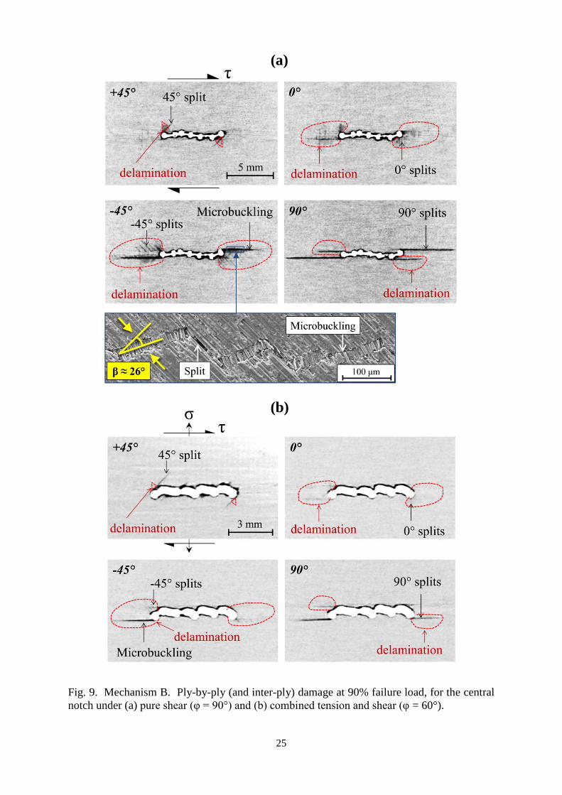
These subcritical damage mechanisms are illustrated in Figure 9(a) and (b). In Figure 9(a), the
specimen was loaded in pure shear (φ = 90°) to 90% failure load, unloaded and CT-scanned. In
Figure 9(b), the specimen was loaded in combined tension and shear (φ = 60°) to 90% failure load.
A detailed post-failure inspection within the Scanning Electron Microscope (SEM) revealed that the
12
microbuckle grew in combination with splitting of the -45° plies, see Figure 9(a), similar to the
phenomenon of microbuckling tunnelling as analysed by Fleck and Zhao [38]. The kink bands in
the -45° plies were observed to be inclined at β ≈ 26°. This lies within the range of kink band
inclination angles (β = 20°-30°) as reviewed by Fleck [14]. The dominant subcritical damage
mechanisms for Mechanism B are splits and microbuckles in the -45° plies. Here, we use the length
of the microbuckles lm in the -45° plies as a measure of damage, see Figure 10. It is clear from the
figure that the evolution of microbuckling is insensitive to the loading angle φ.
3.1.3 Mechanism C
Mechanism C entails microbuckling of the load-bearing 0° plies, as illustrated in Figure 6 for direct
compression. Microbuckles initiate at the notch tip at approximately 80% failure load, consistent
with previous observations in the literature [15,39]. Microbuckling in the adjacent ±45° plies is
also observed prior to failure. Although little splitting is observed, splitting must be present in order
to blunt the severe stress concentration at the notch root: the presence of the notch leads to only a
small knockdown in compressive strength. The existence of these splits is generally recognised
[14,15,39]. The evolution of microbuckling is plotted in Figure 11: lm is the length of the
microbuckle, as measured from its tip to the edge of the notch. For both geometries, the
microbuckles initiate at approximately 80% failure load and grow steadily until a critical length, at
which point catastrophic failure ensures. This is consistent with previous observations [14,39].
4. The effect of geometry upon failure locus: hole versus notch
The failure envelopes of the quasi-isotropic laminate for a notch and circular hole, along with the
regimes of dominance for Mechanisms A, B and C, are presented in Figure 12. Both geometries
exhibit the same mechanisms as a function of loading direction:
(i) Mechanism A for a loading angle φ of 0° to 15°;
13
(ii) Mechanism B for a loading angle φ of 30° to 90°; and
(iii) Mechanism C for a loading angle φ equal to 180° (i.e. direct compression).
Note that the failure envelope for the notch specimen encompasses that for the circular hole over the
full range of φ investigated. This is somewhat surprising as the notch generates a higher stress
concentration than the hole: the stress concentration factor 𝑘𝑇 for the circular hole is on the order
of 3 for tension and 6 for shear loading, whereas the notch induces a value of approximately 6 for
tension and 10 for shear. However, the notch induces greater damage than the hole. Compare, for
example, the damage states for Mechanism A in Figure 13 for the hole with Figure 7(a) for the
notch. The splits induced by the circular hole are significantly shorter than those induced by the
notch, and were not detectable by the X-ray method we employed. Similarly, for Mechanism B (φ
= 90°), the extent of splitting and microbuckling induced by the hole (Figure 14 (a)) are much less
extensive than for the notch (Figure 8(a)); and microbuckle initiation occurs much earlier for the
notch than hole, see Figure 10. A similar trend has been reported for notched tensile specimens in a
recent paper by Xu et al. [13]: sharp notches gave a stronger response than blunt notches. There is
also a striking difference in the shape of the failure envelopes for the two geometries of stress raiser.
The failure envelope is curved for Mechanism B of the circular hole specimens, whereas the failure
envelope of the notch specimens exhibits an almost constant value of shear failure stress for
Mechanism B. The curved failure envelope implies greater interaction between the competing
failure mechanisms.
Interrupted tests on circular hole specimens in the regime of Mechanism B revealed that small
amounts of tensile stress increased the degree of splitting in the specimens. For example, circular
hole specimens loaded at φ equals 60° (Figure 14(b)) had more extensive splits prior to failure than
those loaded at φ equals 90° (Figure 14(a)). The splits in the load-bearing -45° plies relieved the
stress concentration presented by the hole and hence increased the shear failure stress. This
phenomenon was not observed in the notch case: specimens loaded at φ = 60° and 90° had

14
comparable amounts of damage (compare Figure 9(a) and (b)). It is concluded that the notch
generates a sufficiently large stress concentration to induce extensive splits regardless of loading
angle φ for specimens failing by Mechanism B.
5. Concluding discussion
The main features of Mechanism A (splitting, delamination and fibre fractures) are consistent with
those reported in the literature for notched tensile specimens [3–8,11–13]. For example, Xu et al.
[13] reported for a similar specimen geometry (notch length, a = 6.4mm) that the extent of fibre
tensile fracture in a quasi-isotropic laminate is 0.5mm prior to final failure. This is consistent with
our observations. There is also good agreement in the measured strength with values from the
literature. For example, for a similar circular hole specimen, Hallett et al. [8] reported a net section
tensile strength of 550MPa, compared to the value 580MPa as measured here.
Consider next Mechanism B. Subcritical damage initiated first in the form of intra-ply splits near
the stress raisers. This agrees with the findings of Purslow [21] and Hollmann [24,25] for shear
loading. Note that Hollmann [24,25] did not to give a detailed description of damage due to the
existence of limited visualisation technologies at the time. Hollmann [25] observed similar damage
modes but was unable to identify the ply-by-ply failure mode in shear: he assumed that the critical
failure mode was tensile damage in the +45° plies. Herein, we identify microbuckling of the -45°
fibres to be the dominant damage and critical failure mechanism for Mechanism B. The appearance
of the microbuckle, where the fibres break at two points to create a kink band inclined at β ≈ 26°
and where the microbuckle width is approximately 5 times the fibre diameter (see Figure 9(a))
correlates well with the features of a typical microbuckle [14,15]. Additionally, the microbuckle in
the -45° ply of the notch specimen advances in a straight path ahead of the notch. Splits in the
adjacent 90° plies influenced the trajectory of microbuckle growth. This is supported by Soutis

15
[18], who asserts that off-axis plies in multi-directional laminates can influence microbuckling
direction and growth.
The main features of Mechanism C (splitting, delamination and 0° fibre microbuckling) also agree
with previous observations in the literature [14,15, 40]. For example, Soutis et al. [15] and Soutis
[18] found that microbuckling at the notch tip initiates at approximately 80% of the failure load and
grows stably under increasing load to a length of 2-3mm before becoming unstable. This is
supported by our observations. Lee and Soutis [40] also show that the compressive increases with
the degree of splitting at the edge of a hole, due to blocking of the plies.
The present study, for the first time, presents a unified view of damage development and of the
dominant failure mechanisms in quasi-isotropic laminates under combined loading, and highlights
the role of a stress concentration. It is demonstrated that a specimen with a larger stress
concentration can generate greater sub-critical damage and thereby possess a higher net section
strength under combined tension and shear, or direct compression. This study shows that the
amount of damage just prior to peak load is greater for the notch than for the hole, leading to the
higher strength.
Acknowledgements
Financial support from Mitsubishi Heavy Industries (MHI) and the US Office of Naval Research
are gratefully acknowledged.
Appendix A: checks on deformation state in specimen
Figures A1(a) and(b) show representative displacement contours for tension and shear, respectively.
The displacement contours were obtained from Digital Image Correlation (DIC), for specimens at a
load equal to 95% of the failure load. Both figures show symmetric contours indicating that tensile
and shear loading applied through the modified Arcan rig are uniform with negligible in-plane

16
bending. Figure A2 contains the strain gauge measurements for a notch specimen loaded in
compression using the modified Arcan rig. The locations of the strain gauges on the specimen are
included in the figure. It is evident that the degree of in-plane and out-of-plane bending is
negligible – all four strain gauges recorded similar readings. The above measurements support the
use of the modified Arcan rig for the loading modes of the current study.
References
[1] Tan JLY, Deshpande VS, Fleck NA. Predicting the fracture behaviour of notched CFRP laminates
under multi-axial loading (Manuscript in preparation) 2015.
[2] Awerbuch J, Madhukar MS. Notched Strength of Composite Laminates: Predictions and
Experiments--A Review. J Reinf Plast Compos 1985;4:3–159. doi:10.1177/073168448500400102.
[3] Bishop SM. The mechanical performance and impact behaviour of carbon-fibre reinforced PEEK.
Compos Struct 1985;3:295–318.
[4] Lagace PA. Notch sensitivity of graphite/epoxy fabric laminates. Compos Sci Technol 1986;26:95–
117.
[5] Kortschot MT, Beaumont PWR. Damage mechanics of composite materials: l - Measurements of
damage and strength. Compos Sci Technol 1990;39:289–301.
[6] Wang J, Callus PJ, Bannister MK. Experimental and numerical investigation of the tension and
compression strength of un-notched and notched quasi-isotropic laminates. Compos Struct
2004;64:297–306. doi:10.1016/j.compstruct.2003.08.012.
[7] O’Higgins RM, McCarthy M a., McCarthy CT. Comparison of open hole tension characteristics of
high strength glass and carbon fibre-reinforced composite materials. Compos Sci Technol
2008;68:2770–8. doi:10.1016/j.compscitech.2008.06.003.
[8] Hallett SR, Green BG, Jiang WG, Wisnom MR. An experimental and numerical investigation into
the damage mechanisms in notched composites. Compos Part A Appl Sci Manuf 2009;40:613–24.
doi:10.1016/j.compositesa.2009.02.021.
[9] Scott AE, Mavrogordato M, Wright P, Sinclair I, Spearing SM. In situ fibre fracture measurement
in carbon–epoxy laminates using high resolution computed tomography. Compos Sci Technol
2011;71:1471–7. doi:10.1016/j.compscitech.2011.06.004.
17
[10] Sket F, Seltzer R, Molina-Aldareguia JM, Gonzalez C, Llorca J. Determination of damage
micromechanisms and fracture resistance of glass fiber/epoxy cross-ply laminate by means of X-ray
computed microtomography. Compos Sci Technol 2012;72:350–9.
[11] Garg AC. The fracture mechanics of some graphite fibre-reinforced epoxy laminates, Part 1: quasi-
isotropic laminates. Composites 1986;17:141–9.
[12] Carlsson LA, Aronsson CG, Bäcklund J. Notch sensitivity of thermoset and thermoplastic laminates
loaded in tension. J Mater Sci 1989;24:1670–82.
[13] Xu X, Wisnom MR, Mahadik Y, Hallett SR. An Experimental Investigation into Size Effects in
Quasi-isotropic Carbon/Epoxy Laminates with Sharp and Blunt Notches. Compos Sci Technol
2014. doi:10.1016/j.compscitech.2014.06.002.
[14] Fleck NA. Compressive failure of fibre composites. Adv Appl Mech 1997;33:43–117.
[15] Soutis C, Curtis PT, Fleck NA. Compressive failure of notched carbon fibre composites. Proc R Soc
London Ser A Math Phys Sci 1993;440:241–56. doi:10.1098/rspa.1993.0014.
[16] Sivashanker S, Fleck NA, Sutcliffe MPF. Microbuckle propagation in a unidirectional carbon fibe-
epoxy matrix composite. Acta Mater 1996;44:2581–90.
[17] Moran PM, Liu XH, Shih CF. Kink band formation and band broadening in fiber composites under
compressive loading. Acta Metall Mater 1995;43:2943–58.
[18] Soutis C. Damage tolerance of open-hole CFRP laminates loaded in compression. Compos Eng
1994;4:317–27.
[19] Purslow D. Some fundamental aspects of composites fractography. Composites 1981;12:241–7.
[20] Purslow D. Fractographic analysis of failures in CFRP. ‘Characterization, Anal. Significance
Defects Compos. Mater. AGARD CP 355, 1983, p. 1–11.
[21] Purslow D. Matrix fractography of fibre-reinforced thermoplastics, part 2. shear failures.
Composites 1988;19:115–26.
[22] Broughton WR, Kumosa M, Hull D. Analysis of the Iosipescu shear test as applied to unidirectional
carbon-fibre reinforced composites. Compos Sci Technol 1990;38:299–325.
[23] Jelf PM, Fleck NA. The failure of composite tubes due to combined compression and torsion. J
Mater Sci 1994;29:3080–4.
[24] Hollmann K. In-plane shear failure analysis of notched composites. Compos Sci Technol
1991;41:257–85.
[25] Hollmann K. Failure analysis of a shear loaded graphite/epoxy beam containing an irregular cutout.
Eng Fract Mech 1991;39:159–75. doi:10.1016/0013-7944(91)90031-U.
[26] Vogler TJ, Kyriakides S. Inelastic behavior of an AS4-PEEK composite under combined transverse
compression and shear. Part I: experiments. Int J Plast 1999;15:783–806.

18
[27] Totry E, Molina-Aldareguia JM, Gonzalez C, Llorca J. Effect of fiber, matrix and interface
properties on the in-plane shear deformation of carbon-fiber reinforced composites. Compos Sci
Technol 2010;70:970–80.
[28] Wu EM. Application of Fracture Mechanics to Anisotropic Plates. J Appl Mech 1967;34:967.
[29] Francis PH, Walrath DE, Weed DN. First ply failure of G/E laminates under biaxial loadings. Fibre
Sci Technol 1979;12:97–110.
[30] Gilchrist MD, Svensson N. A fractographic analysis of delamination within multidirectional
carbon/epoxy laminates. Compos Sci Technol 1995;55:195–207. doi:10.1016/0266-3538(95)00099-
2.
[31] Gning PB, Delsart D, Mortier JM, Coutellier D. Through-thickness strength measurements using
Arcan’s method. Compos Part B Eng 2010;41:308–16. doi:10.1016/j.compositesb.2010.03.004.
[32] Laffan MJ, Pinho ST, Robinson P, Iannucci L. Measurement of the in situ ply fracture toughness
associated with mode I fibre tensile failure in FRP. Part II: Size and lay-up effects. Compos Sci
Technol 2010;70:614–21. doi:10.1016/j.compscitech.2009.12.011.
[33] Arcan M, Hashin Z, Voloshin a. A method to produce uniform plane-stress states with applications
to fiber-reinforced materials. Exp Mech 1978;18:141–6. doi:10.1007/BF02324146.
[34] Tan KT, Watanabe N, Iwahori Y. X-ray radiography and micro-computed tomography examination
of damage characteristics in stitched composites subjected to impact loading. Compos Part B Eng
2011;42:874–84. doi:10.1016/j.compositesb.2011.01.011.
[35] Freeman SM. Characterization of lamina and interlaminar damage in graphite/epoxy composite by
the deply technique. ASTM STP 787 1982:50–62.
[36] Spearing SM, Beaumont PWR. Fatigue damage mechanics of composite materials. I: Experimental
measurement of damage and post-fatigue properties. Compos Sci Technol 1992;44:159–68.
doi:10.1016/0266-3538(92)90109-G.
[37] De Morais AB. Open-hole tensile strength of quasi-isotropic laminates. Compos Sci Technol
2000;60:1997–2004.
[38] Fleck NA, Zhao LG. Microbuckle tunnelling in fibre composites. J Mech Phys Solids
2000;48:1865–91.
[39] Soutis C, Fleck NA, Curtis PT. Hole-hole interaction in carbon fibre/epoxy laminates under uniaxial
compression. Composites 1991;22:31–8.
[40] Lee J, Soutis C. Measuring the notched compressive strength of composite laminates: Specimen
size effects. Compos Sci Technol 2008;68:2359–66.

19
Figure captions
Fig. 1. Specimen configuration (w = 25mm; l1 = 33.5mm; l2 = 23mm; notch: a = 6.25mm, b =
0.7mm; circular hole: a = 6mm; total thickness, B = 2mm).
Fig. 2. (a) The modified Arcan rig; (b) Photograph of test set-up (configured for shear).
Fig. 3. Photographs of the failed specimens.
Fig. 4. Typical load-displacement curves. The load was measured by the load cell of the test
machine and the displacement was measured by DIC over a gauge length of 23mm.
Fig. 5. Failure envelope for the notch case.
Fig. 6. The dominant damage and critical failure mechanisms for each mode of loading.
Fig. 7. Mechanism A. Ply-by-ply (and inter-ply) damage at 90% failure load, for the central
notch under (a) pure tension (φ = 0°) and (b) combined tension and shear (φ = 15°).
Fig. 8. Evolution of 0° splits in Mechanism A (notch). P is the remote applied load and Pf is the
peak load. For φ = 0°, Pf = 23.5kN and for φ = 15°, Pf = 22.2kN. 𝑙𝑠 is the length of the 0° split.
Fig. 9. Mechanism B. Ply-by-ply (and inter-ply) damage at 90% failure load, for the central
notch under (a) pure shear (φ = 90°) and (b) combined tension and shear (φ = 60°).
Fig. 10. Evolution of microbuckling in Mechanism B. P is the remote applied load and Pf is the
peak load. For the notch, Pf = 9.9kN when φ = 90°, and Pf = 12.5kN when φ = 60°. For the hole,
Pf = 6.99kN when φ = 90°, and Pf = 9.80kN when φ = 60°. 𝑙𝑚 is the length of the microbuckle in
the -45° ply.
Fig. 11. Evolution of microbuckling in Mechanism C. P is the remote applied load and Pf is the
peak load. For the notch, Pf = 13.8kN and for the hole, Pf = 13.2kN. 𝑙𝑚 is the length of the
microbuckle in the 0° ply.
Fig. 12. Failure envelopes of the quasi-isotropic laminate with a central notch and circular hole.
Fig. 13. Ply-by-ply (and inter-ply) damage in the quasi-isotropic specimen with a central
circular hole under pure tension (φ = 0°) at 90% failure load (Mechanism A).
Fig. 14. Mechanism B, for a specimen with central hole at 90% failure load. Damage for (a)
pure shear (φ = 90°), and (b) combined tension and shear (φ = 60°).
Fig. A1. (a) DIC displacement contours (2-direction) on a specimen with a notch that was
loaded in pure tension using the modified Arcan rig (95% failure load); (b) DIC displacement
contours (1-direction) on a specimen with a notch that was loaded in simple shear using the
modified Arcan rig (95% failure load). Displacements in mm.
Fig. A2. Strain gauge measurements to check for bending in compression test.

20
Table 1. Average peak loads and strengths of specimens with a notch.
Loading angle, φ (°) Peak load, Pf (kN) Tensile strength, σ (MPa) Shear strength, τ (MPa)
0 23.5 626 0
15 22.2 572 153
30 20.3 468 270
45 14.2 268 268
60 12.5 166 288
75 10.3 71 266
90 9.90 0 264
180 13.8 -367 0
Table 2. Average peak loads and strengths of specimens with a circular hole.
Loading angle, φ (°) Peak load, Pf (kN) Tensile strength, σ (MPa) Shear strength, τ (MPa)
0 21.1 555 0
15 19.9 507 136
30 15.6 355 205
45 12.1 226 226
60 9.80 129 223
75 7.93 54 202
90 6.99 0 184
180 13.2 -347 0

21
Fig. 1. Specimen configuration (w = 25mm; l1 = 33.5mm; l2 = 23mm; notch: a = 6.25mm, b =
0.7mm; circular hole: a = 6mm; total thickness, B = 2mm).
(a) (b)
Fig. 2. (a) The modified Arcan rig; (b) Photograph of test set-up (configured for shear).

22
Fig. 3. Photographs of the failed specimens.
Fig. 4. Typical load-displacement curves. The load was measured by the machine load cell
and the displacement was measured by DIC over a gauge length of 23mm.

23
Fig. 5. Failure envelope for the notch case. .
Fig. 6. The dominant damage and critical failure mechanisms for each mode of loading.

24
Fig. 7. Mechanism A. Ply-by-ply (and inter-ply) damage at 90% failure load, for the central
notch under (a) pure tension (φ = 0°) and (b) combined tension and shear (φ = 15°).
Fig. 8. Evolution of 0° splits in Mechanism A (notch). P is the remote applied load and Pf is
the peak load. For φ = 0°, Pf = 23.5kN and for φ = 15°, Pf = 22.2kN. 𝑙𝑠 is the length of the 0°
split.
(a)
(b)
25
Fig. 9. Mechanism B. Ply-by-ply (and inter-ply) damage at 90% failure load, for the central
notch under (a) pure shear (φ = 90°) and (b) combined tension and shear (φ = 60°).
(a)
(b)

26
Fig. 10. Evolution of microbuckling in Mechanism B. P is the remote applied load and Pf is
the peak load. For the notch, Pf = 9.90kN when φ = 90°, and Pf = 12.5kN when φ = 60°. For
the hole, Pf = 6.99kN when φ = 90°, and Pf = 9.80kN when φ = 60°. 𝑙𝑚 is the length of the
microbuckle in the -45° ply.
Fig. 11. Evolution of microbuckling in Mechanism C. P is the remote applied load and Pf is
the peak load. For the notch, Pf = 13.8kN and for the hole, Pf = 13.2kN. 𝑙𝑚 is the length of the
microbuckle in the 0° ply.

27
Fig. 12. Failure envelopes of the quasi-isotropic laminate with a central notch and circular
hole.
Fig. 13. Ply-by-ply (and inter-ply) damage in the quasi-isotropic specimen with a central
circular hole under pure tension (φ = 0°) at 90% failure load (Mechanism A).

28
Fig. 14. Mechanism B, for a specimen with central hole at 90% failure load. Damage for (a)
pure shear (φ = 90°), and (b) combined tension and shear (φ = 60°).
(b)
(a)

29
(a) (b)
Fig. A1. (a) DIC displacement contours (2-direction) on a specimen with a notch that was
loaded in pure tension using the modified Arcan rig (95% failure load); (b) DIC
displacement contours (1-direction) on a specimen with a notch that was loaded in simple
shear using the modified Arcan rig (95% failure load). Displacements in mm.
Fig. A2. Strain gauge measurements to check for bending in compression test.