fairfield inn & suites, marriot pittsburgh, pa · design loads & criteria………… ......
TRANSCRIPT
4/7/2010
Amanda Smith | Advisor: Dr. Ali Memari Structural Option
SENIOR THESIS
FINAL REPORT
FAIRFIELD INN & SUITES, MARRIOT
PITTSBURGH, PA
Fairfield Inn & Suites, Marriot
Pittsburgh, PA Amanda Smith
Final Thesis Report
P a g e | 2
Fairfield Inn & Suites, Marriot
Pittsburgh, PA Amanda Smith
Final Thesis Report
P a g e | 3
TABLE OF CONTENTS
Acknowledgements .…………….…………………………………………………………………………………………5
Executive Summary………………………………………………………………………………………………………...6
Building Overview ………………………………………………………………………………………………………….7
Existing Structural System………………………………………………………………………….…………………10
Architectural & Structural Plans ………………..……………...………………………………….……….………14
Proposal Background & Project Goals……..…………………………………………………………………….16
Structural Study (Depth).….……………………………………………………………………….………………….18
Gravity System Redesign……………………………………………………………………………………18
Design Loads & Criteria……………..…………………………………………………………….18 Design Process………………………………………………………………………………...………20 Connection Design…………………………………………………………………………………..25 Design Summary and Conclusions………………………………………………………..…..27
Lateral Force Resisting System Redesign……………………………………………………….……28
Design Loads & Criteria…………………………………………………………………………...28 Design Process………………………………………………………………………………….…….32 Optimization Study………………………………………………………………………………….37 Design Summary and Conclusions……………………………………………………………47
Impact on Foundation..…………………………………………………………………………………..…..48
Breadth Study I: Façade Study………………………………..………………………………...……..…………….51
Breadth Study II: Construction Management.………………………….……………...……………………...55
Conclusions and Recommendations……………….….………………………………………………...………...59
Code References …………………………………………………………………………………………………………..60
Fairfield Inn & Suites, Marriot
Pittsburgh, PA Amanda Smith
Final Thesis Report
P a g e | 4
TABLE OF CONTENTS
Appendix A: Gravity System Redesigned Calculations……………………………………….……………61
Appendix B: Wind & Seismic Load Analysis………………………………………..……………………..……78
Appendix C: Shear Wall Design …………………..………………………….…………………………………...…89
Appendix D: Lateral Optimization Study …………..…………….......................................................………99
Appendix E: Foundation Check ……………………………………………..……………….…………..………..114
Appendix F: Façade Study Calculations ………………………………………………………………….……118
Appendix G: Construction Schedule & Cost Calculations ………………………………………………122
Fairfield Inn & Suites, Marriot
Pittsburgh, PA Amanda Smith
Final Thesis Report
P a g e | 5
ACKNOWLEDGEMENTS
I would like to thank the following companies and individuals for their assistance and
continuous support throughout the duration of this thesis project:
Atlantic Engineering Services:
Tim Jones Robert Bertocchi Massaro Corporation:
Brian Miller
G.M.McCrossin Contracting:
Shawn Steward
SNC-Lavalin America:
Jeremy Columbe
The Pennsylvania State University:
Dr. Ali Memari Prof. M Kevin Parfitt Prof. Robert Holland The entire AE faculty and staff
I would also like to thank my family and friends.
Lastly, a very special thank you to my parents and fiancé for all your continued love and
support.

Fairfield Inn & Suites, Marriot
Pittsburgh, PA Amanda Smith
Final Thesis Report
P a g e | 6
EXECUTIVE SUMMARY
The Fairfield Inn and Suites is a 10 story hotel located in downtown Pittsburgh, Pennsylvania. The building is approximately 80,000 square feet and reaches a height of 102’ above grade with a typical floor to floor height of approximately 9’4”. The current site of the Fairfield Inn and Suites was chosen because it’s adjacent location to PNC Park and close proximity to Heinz Field in Pittsburgh. For these reasons, the hotel was kept on the existing site. Upon investigation of the soil classification for the site, it was determined that the soil is classified Site Class D. This will significantly impact the base shear value of the building, due to the poor soil the foundation will rest on. This final thesis study examined the implications related to redesigning the gravity and lateral systems of the Fairfield Inn and Suites. The current design of the building includes load bearing concrete masonry walls, transfer beams, and an auger cast pile foundation. The redesign completed in the structural depth study explored steel moment frames rather than the load bearing concrete masonry walls. This would eliminate the use of the transfer beams in the current design. The design also examined a modified layout in the shear walls that result in the lateral force resisting system of the building. The steel gravity system resulted in a decrease to the overall building weight. Along with the decrease to the overall building weight, the construction time to erect the steel building structure was sufficiently lower than the concrete masonry bearing structure. The shorter construction time does sacrifice an increase in cost. Structurally, the redesign of the gravity system does prove to be an efficient option for the building. The decrease in building weight resulted in a reduced base shear value on the building. A lateral optimization study was included as part of the structural depth study to see if a modified shear wall layout would provide greater resistance to the loads. The modified layout proved to be the optimal design as it reduced the overall torsion present on the building and reduced the required number of piles in the foundation. The façade breadth study focuses on improvements in guest comfort with respect to
natural daylight penetration verse heat transfer through the wall system. By implementing
the brick veneer system, the heat transfer through the wall would not be affected, as
opposed to using the larger curtain wall system façade option which would increase the
heat transfer but allow for more natural daylight. A lower heat transfer rate façade proves
to me a more efficient system for the building.
The goals of this thesis were to create an efficient optional gravity and lateral system for
the building. Based on the results discussed, these goals are clearly met. If cost was not an
issue, it is the recommendation of the author to implement the changes proposed, as each
study does impact the building in a positive way.
Fairfield Inn & Suites, Marriot
Pittsburgh, PA Amanda Smith
Final Thesis Report
P a g e | 7
BUILDING OVERVIEW
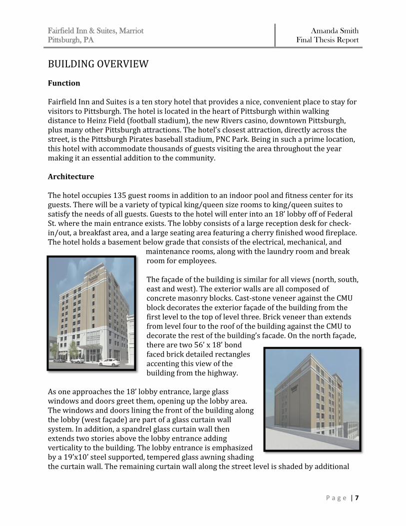
Function Fairfield Inn and Suites is a ten story hotel that provides a nice, convenient place to stay for visitors to Pittsburgh. The hotel is located in the heart of Pittsburgh within walking distance to Heinz Field (football stadium), the new Rivers casino, downtown Pittsburgh, plus many other Pittsburgh attractions. The hotel’s closest attraction, directly across the street, is the Pittsburgh Pirates baseball stadium, PNC Park. Being in such a prime location, this hotel with accommodate thousands of guests visiting the area throughout the year making it an essential addition to the community. Architecture The hotel occupies 135 guest rooms in addition to an indoor pool and fitness center for its guests. There will be a variety of typical king/queen size rooms to king/queen suites to satisfy the needs of all guests. Guests to the hotel will enter into an 18’ lobby off of Federal St. where the main entrance exists. The lobby consists of a large reception desk for check-in/out, a breakfast area, and a large seating area featuring a cherry finished wood fireplace. The hotel holds a basement below grade that consists of the electrical, mechanical, and
maintenance rooms, along with the laundry room and break room for employees. The façade of the building is similar for all views (north, south, east and west). The exterior walls are all composed of concrete masonry blocks. Cast-stone veneer against the CMU block decorates the exterior façade of the building from the first level to the top of level three. Brick veneer than extends from level four to the roof of the building against the CMU to decorate the rest of the building’s facade. On the north façade, there are two 56’ x 18’ bond faced brick detailed rectangles accenting this view of the building from the highway.
As one approaches the 18’ lobby entrance, large glass windows and doors greet them, opening up the lobby area. The windows and doors lining the front of the building along the lobby (west façade) are part of a glass curtain wall system. In addition, a spandrel glass curtain wall then extends two stories above the lobby entrance adding verticality to the building. The lobby entrance is emphasized by a 19’x10’ steel supported, tempered glass awning shading the curtain wall. The remaining curtain wall along the street level is shaded by additional
Fairfield Inn & Suites, Marriot
Pittsburgh, PA Amanda Smith
Final Thesis Report
P a g e | 8
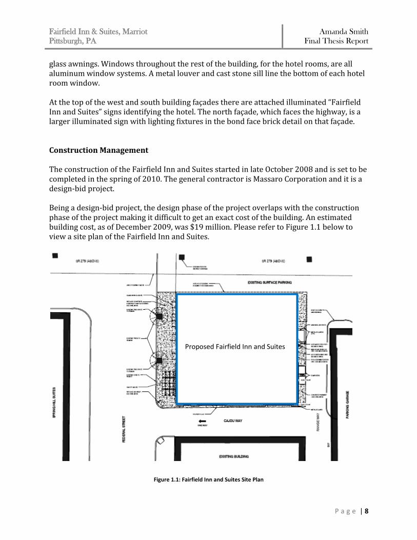
glass awnings. Windows throughout the rest of the building, for the hotel rooms, are all aluminum window systems. A metal louver and cast stone sill line the bottom of each hotel room window. At the top of the west and south building façades there are attached illuminated “Fairfield Inn and Suites” signs identifying the hotel. The north façade, which faces the highway, is a larger illuminated sign with lighting fixtures in the bond face brick detail on that façade. Construction Management The construction of the Fairfield Inn and Suites started in late October 2008 and is set to be completed in the spring of 2010. The general contractor is Massaro Corporation and it is a design-bid project. Being a design-bid project, the design phase of the project overlaps with the construction phase of the project making it difficult to get an exact cost of the building. An estimated building cost, as of December 2009, was $19 million. Please refer to Figure 1.1 below to view a site plan of the Fairfield Inn and Suites.
Figure 1.1: Fairfield Inn and Suites Site Plan
Proposed Fairfield Inn and Suites
Fairfield Inn & Suites, Marriot
Pittsburgh, PA Amanda Smith
Final Thesis Report
P a g e | 9
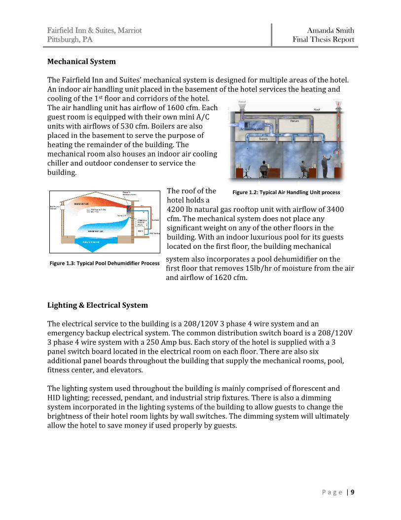
Mechanical System The Fairfield Inn and Suites’ mechanical system is designed for multiple areas of the hotel. An indoor air handling unit placed in the basement of the hotel services the heating and cooling of the 1st floor and corridors of the hotel. The air handling unit has airflow of 1600 cfm. Each guest room is equipped with their own mini A/C units with airflows of 530 cfm. Boilers are also placed in the basement to serve the purpose of heating the remainder of the building. The mechanical room also houses an indoor air cooling chiller and outdoor condenser to service the building.
The roof of the hotel holds a 4200 lb natural gas rooftop unit with airflow of 3400 cfm. The mechanical system does not place any significant weight on any of the other floors in the building. With an indoor luxurious pool for its guests located on the first floor, the building mechanical
system also incorporates a pool dehumidifier on the first floor that removes 15lb/hr of moisture from the air and airflow of 1620 cfm.
Lighting & Electrical System The electrical service to the building is a 208/120V 3 phase 4 wire system and an emergency backup electrical system. The common distribution switch board is a 208/120V 3 phase 4 wire system with a 250 Amp bus. Each story of the hotel is supplied with a 3 panel switch board located in the electrical room on each floor. There are also six additional panel boards throughout the building that supply the mechanical rooms, pool, fitness center, and elevators. The lighting system used throughout the building is mainly comprised of florescent and HID lighting; recessed, pendant, and industrial strip fixtures. There is also a dimming system incorporated in the lighting systems of the building to allow guests to change the brightness of their hotel room lights by wall switches. The dimming system will ultimately allow the hotel to save money if used properly by guests.
Figure 1.2: Typical Air Handling Unit process
Figure 1.3: Typical Pool Dehumidifier Process
Fairfield Inn & Suites, Marriot
Pittsburgh, PA Amanda Smith
Final Thesis Report
P a g e | 10
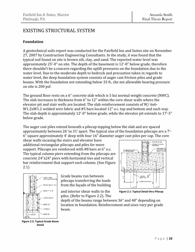
EXISTING STRUCTURAL SYSTEM Foundation A geotechnical soils report was conducted for the Fairfield Inn and Suites site on November 27, 2007 by Construction Engineering Consultants. In the study, it was found that the typical soil found on site is brown silt, clay, and sand. The reported water level was approximately 25’-0” on site. The depth of the basement is 12’-8” below grade, therefore there shouldn’t be a concern regarding the uplift pressures on the foundation due to the water level. Due to the moderate depth to bedrock and precaution taken in regards to water level, the deep foundation system consists of auger cast friction piles and grade beams. With the foundation not extending below 33 ft., the net allowable bearing pressure on site is 200 psf. The ground floor rests on a 6” concrete slab which is 5 ksi normal weight concrete (NWC). The slab increases in thickness from 6” to 12” within the core shear walls where the elevator pit and stair wells are located. The slab reinforcement consists of W/ 6x6-W1.2xW1.2 welded wire fabric and #5 bars located 12” o.c. top and bottom and each way. The slab depth is approximately 12’-0” below grade, while the elevator pit extends to 17’-5” below grade. The auger cast piles extend beneath a pilecap topping below the slab and are spaced approximately between 26’ to 31’ apart. The typical size of the foundation pilecaps are a 7’-6” square approximately 4’ deep with four 16” diameter auger cast piles per cap. The core shear walls incasing the stairs and elevator have additional rectangular pilecaps and piles for more support. Pilecaps are reinforced with #8 bars at 6” o.c. The typical column piers extending from the pilecaps are concrete 24”x24” piers with horizontal ties and vertical bar reinforcement that support each column. (See Figure 2.1)
Grade beams run between pilecaps transferring the loads from the façade of the building
and interior shear walls to the piles. (Refer to Figure 2.2). The depth of the beams range between 36” and 48” depending on location in foundation. Reinforcement and sizes vary per grade beam.
Figure 2.1: Typical Detail thru Pilecap
Figure 2.2: Typical Grade Beam Detail
Fairfield Inn & Suites, Marriot
Pittsburgh, PA Amanda Smith
Final Thesis Report
P a g e | 11
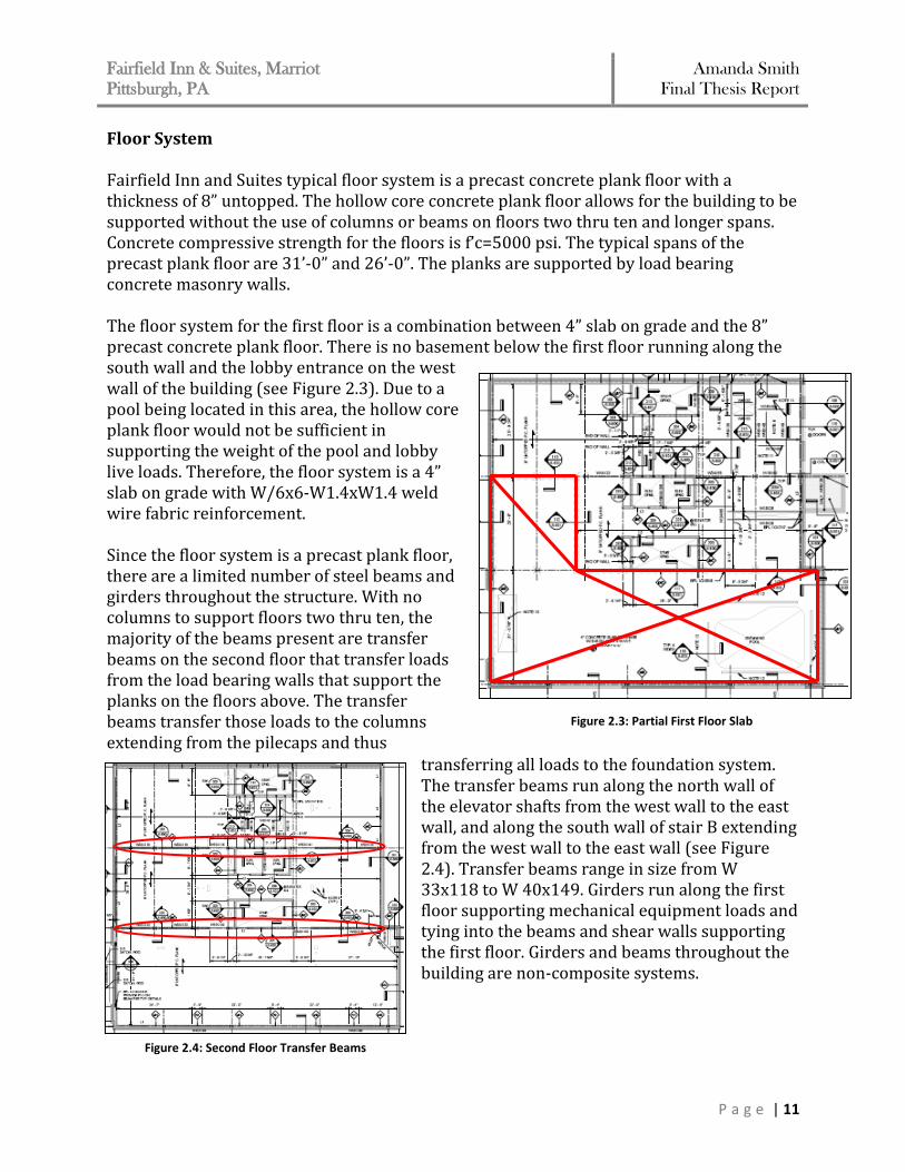
Floor System Fairfield Inn and Suites typical floor system is a precast concrete plank floor with a thickness of 8” untopped. The hollow core concrete plank floor allows for the building to be supported without the use of columns or beams on floors two thru ten and longer spans. Concrete compressive strength for the floors is f’c=5000 psi. The typical spans of the precast plank floor are 31’-0” and 26’-0”. The planks are supported by load bearing concrete masonry walls. The floor system for the first floor is a combination between 4” slab on grade and the 8” precast concrete plank floor. There is no basement below the first floor running along the south wall and the lobby entrance on the west wall of the building (see Figure 2.3). Due to a pool being located in this area, the hollow core plank floor would not be sufficient in supporting the weight of the pool and lobby live loads. Therefore, the floor system is a 4” slab on grade with W/6x6-W1.4xW1.4 weld wire fabric reinforcement. Since the floor system is a precast plank floor, there are a limited number of steel beams and girders throughout the structure. With no columns to support floors two thru ten, the majority of the beams present are transfer beams on the second floor that transfer loads from the load bearing walls that support the planks on the floors above. The transfer beams transfer those loads to the columns extending from the pilecaps and thus
transferring all loads to the foundation system. The transfer beams run along the north wall of the elevator shafts from the west wall to the east wall, and along the south wall of stair B extending from the west wall to the east wall (see Figure 2.4). Transfer beams range in size from W 33x118 to W 40x149. Girders run along the first floor supporting mechanical equipment loads and tying into the beams and shear walls supporting the first floor. Girders and beams throughout the building are non-composite systems.
Figure 2.3: Partial First Floor Slab
Figure 2.4: Second Floor Transfer Beams
Fairfield Inn & Suites, Marriot
Pittsburgh, PA Amanda Smith
Final Thesis Report
P a g e | 12
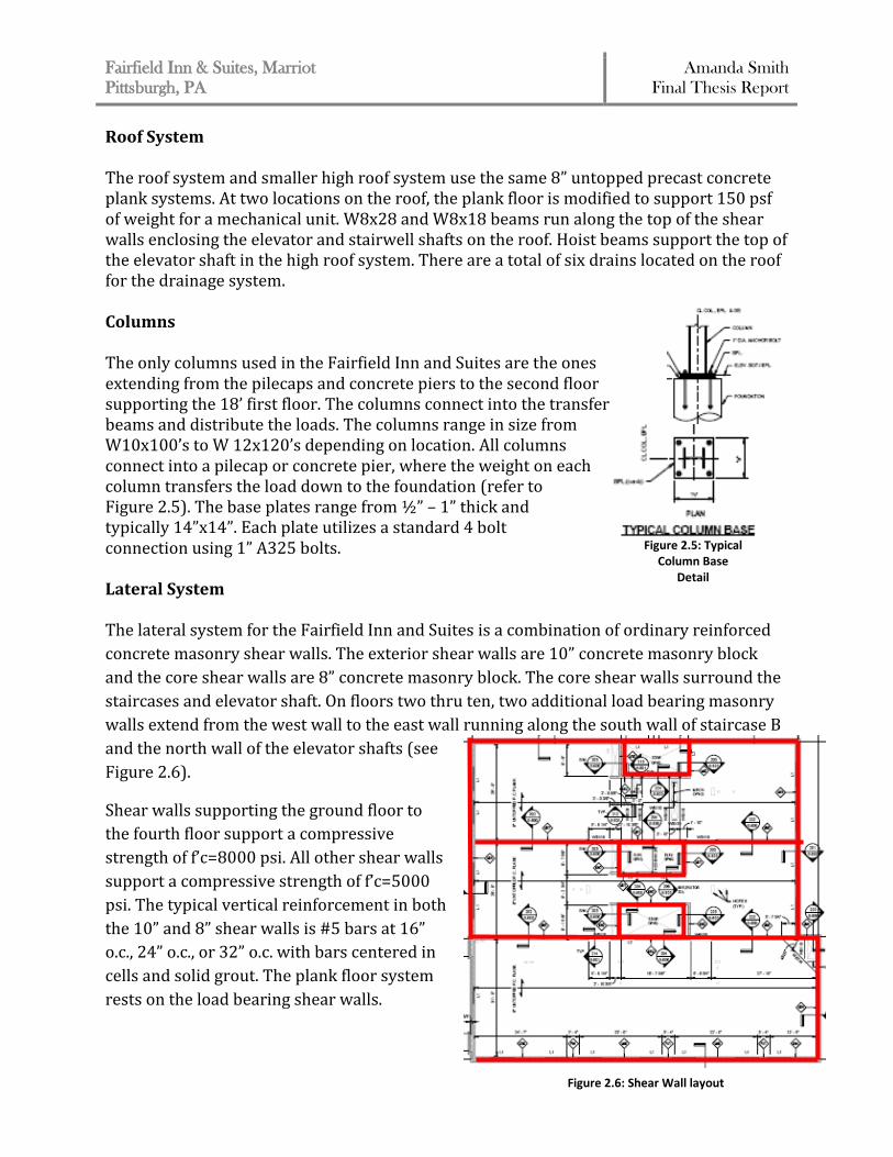
Roof System The roof system and smaller high roof system use the same 8” untopped precast concrete plank systems. At two locations on the roof, the plank floor is modified to support 150 psf of weight for a mechanical unit. W8x28 and W8x18 beams run along the top of the shear walls enclosing the elevator and stairwell shafts on the roof. Hoist beams support the top of the elevator shaft in the high roof system. There are a total of six drains located on the roof for the drainage system. Columns The only columns used in the Fairfield Inn and Suites are the ones extending from the pilecaps and concrete piers to the second floor supporting the 18’ first floor. The columns connect into the transfer beams and distribute the loads. The columns range in size from W10x100’s to W 12x120’s depending on location. All columns connect into a pilecap or concrete pier, where the weight on each column transfers the load down to the foundation (refer to Figure 2.5). The base plates range from ½” – 1” thick and typically 14”x14”. Each plate utilizes a standard 4 bolt connection using 1” A325 bolts. Lateral System The lateral system for the Fairfield Inn and Suites is a combination of ordinary reinforced
concrete masonry shear walls. The exterior shear walls are 10” concrete masonry block
and the core shear walls are 8” concrete masonry block. The core shear walls surround the
staircases and elevator shaft. On floors two thru ten, two additional load bearing masonry
walls extend from the west wall to the east wall running along the south wall of staircase B
and the north wall of the elevator shafts (see
Figure 2.6).
Shear walls supporting the ground floor to
the fourth floor support a compressive
strength of f’c=8000 psi. All other shear walls
support a compressive strength of f’c=5000
psi. The typical vertical reinforcement in both
the 10” and 8” shear walls is #5 bars at 16”
o.c., 24” o.c., or 32” o.c. with bars centered in
cells and solid grout. The plank floor system
rests on the load bearing shear walls.
Figure 2.5: Typical Column Base
Detail
Figure 2.6: Shear Wall layout
Fairfield Inn & Suites, Marriot
Pittsburgh, PA Amanda Smith
Final Thesis Report
P a g e | 13
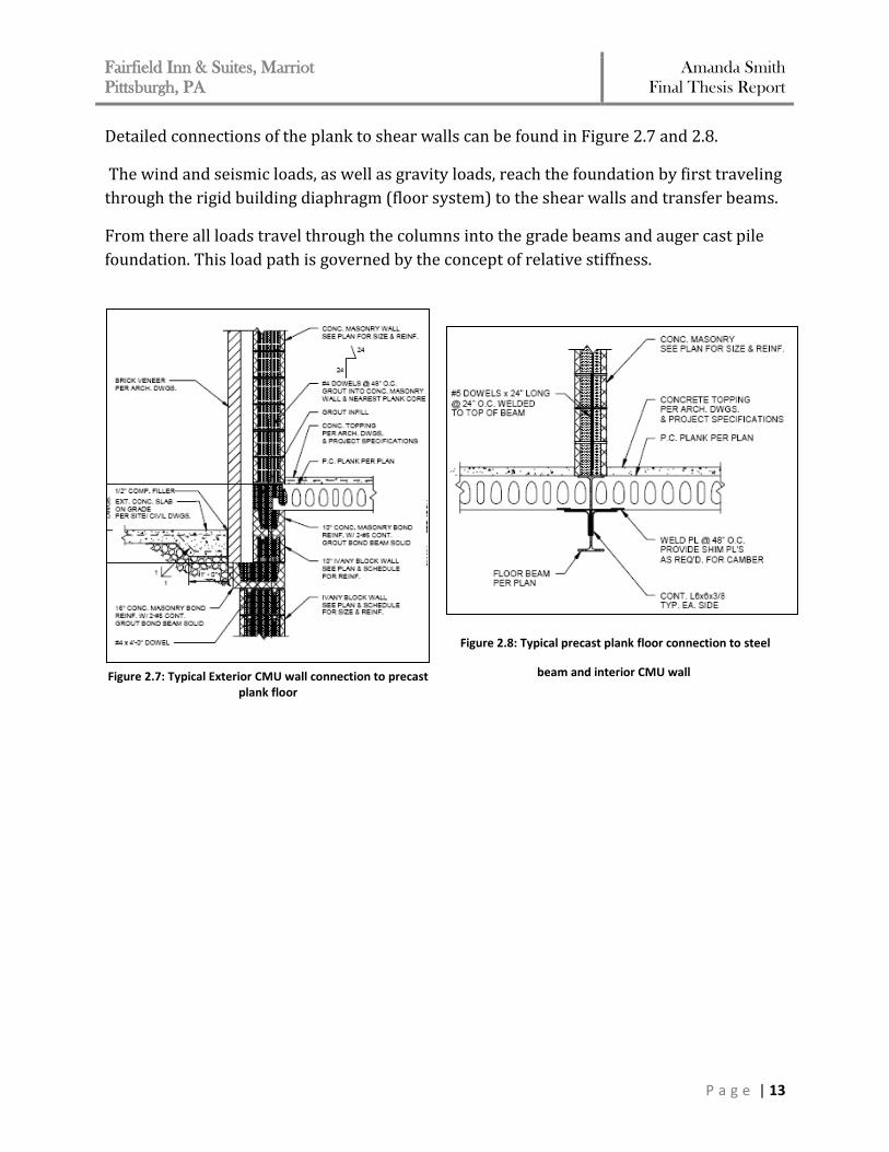
Detailed connections of the plank to shear walls can be found in Figure 2.7 and 2.8.
The wind and seismic loads, as well as gravity loads, reach the foundation by first traveling
through the rigid building diaphragm (floor system) to the shear walls and transfer beams.
From there all loads travel through the columns into the grade beams and auger cast pile
foundation. This load path is governed by the concept of relative stiffness.
Figure 2.8: Typical precast plank floor connection to steel
beam and interior CMU wall
Figure 2.7: Typical Exterior CMU wall connection to precast plank floor
Fairfield Inn & Suites, Marriot
Pittsburgh, PA Amanda Smith
Final Thesis Report
P a g e | 14
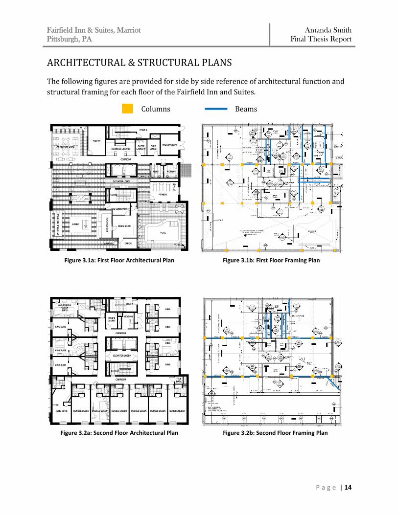
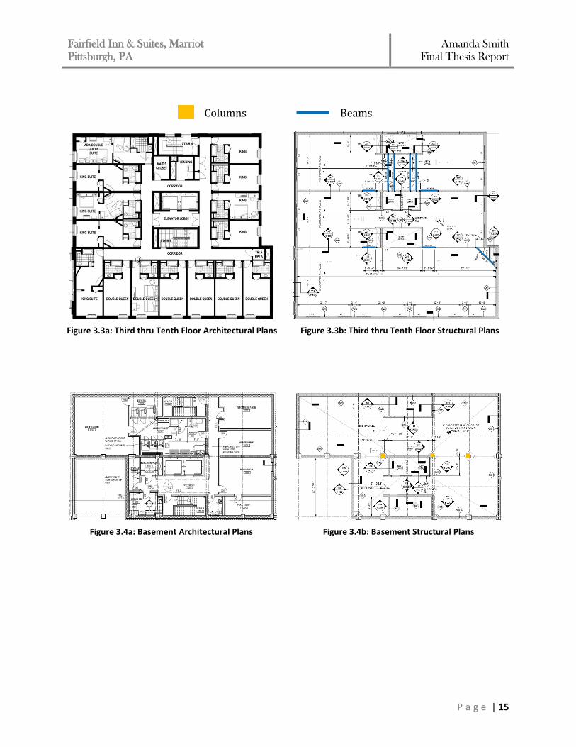
ARCHITECTURAL & STRUCTURAL PLANS
The following figures are provided for side by side reference of architectural function and
structural framing for each floor of the Fairfield Inn and Suites.
Columns Beams
Figure 3.1a: First Floor Architectural Plan Figure 3.1b: First Floor Framing Plan
Figure 3.2a: Second Floor Architectural Plan Figure 3.2b: Second Floor Framing Plan
Fairfield Inn & Suites, Marriot
Pittsburgh, PA Amanda Smith
Final Thesis Report
P a g e | 15
Columns Beams
Figure 3.3a: Third thru Tenth Floor Architectural Plans Figure 3.3b: Third thru Tenth Floor Structural Plans
Figure 3.4a: Basement Architectural Plans Figure 3.4b: Basement Structural Plans
Fairfield Inn & Suites, Marriot
Pittsburgh, PA Amanda Smith
Final Thesis Report
P a g e | 16
PROPOSAL BACKGROUND AND PROJECT GOALS
Problem Statement The nature of this site for the Fairfield Inn and Suites had an impact on the structural design of the building. Based on the field and laboratory test data within the geotechnical report for the site, it was determined that the soil on site is poor and classified as soil class D. This significantly impacted the base shear value, leading the building to be seismically controlled even when torsion effects were considered. The auger cast piles design of the foundation system for the building was designed to best fit this criterion and support the building in this soil class. The possibility of increased loads to the building and other implications resulting from the implementation of any new system, will require checks to be done at the foundation to verify it is sufficient to withstand changes or whether or not alterations must be made if at all feasible. The existing structural design of the building meets all required design requirements as per ASCE 07 and any code requirements concerning restrictions due to location or zoning. Therefore, when considering an alternative design to this building, the final decision may not prove to be more effective compared to the existing design. However, a further investigation of other options to the building design should be considered. With the number of load bearing concrete masonry walls making up the building, it results in a very high overall building weight that must be supported in such a poor soil site. For such a poor soil class, a lighter building weight would be suggested for the design to enhance its supporting foundation. A redesign of the structural system of the existing Fairfield Inn and Suites will be designed in an attempt to find an equally effective and efficient building system. To determine whether a different system is equally efficient and effective, it will be compared to the existing system in a number of categories. Proposed Solution Due to the nature of the soil, steel may be the best viable solution for the design of the structural system. Concrete is a heavier material by nature, therefore the steel could only decrease the weight of the building, creating a lighter base shear value. As a result, a viable alternative structural system for the Fairfield Inn and Suites is altering the framing system to a steel frame. This consequently will affect the foundation and construction management issues like schedule and cost. The architecture of the building could also be impacted without the exterior shear walls present. In addition, since the controlling lateral load case is seismic, changing the building frame to steel may reduce those loads due to stiffness. With a steel framing system, an alteration to the lateral force resisting system and gravity resisting system will be considered. The current hollow core plank floor system will remain as it proved to be the most efficient floor system solution. The plank floor system will sit

Fairfield Inn & Suites, Marriot
Pittsburgh, PA Amanda Smith
Final Thesis Report
P a g e | 17
on steel non-composite girders rather than the existing load bearing masonry walls. The majority of the load bearing masonry walls will be eliminated from the structural design. The shear walls will only remain in the core of the building surrounding the staircases and elevator shaft. The core shear walls will now be what make up the lateral force resisting system. The shear walls will be redesigned in order to withstand the lateral loads. An optimization study will be performed to verify the new design. Steel moment frames will be designed to resist the gravity loads placed on the building. All relative structural elements of the building will have to be considered throughout this alternate design. Since the redesign incorporates a different primary material for the building, steel, the existing columns and transfer beams will be altered. The floor spans and location of the floor framing members will remain unchanged. The location of the interior load bearing masonry walls will be replaced by steel columns and non-composite moment frames. Instead of steel columns extending from the auger cast piles to the second floor transfer beams, they will now extend to the roof of the building. This will ultimately eliminate the use of transfer beams at the second floor. Finally, an analysis will be done to the foundation to ensure the new lateral loads and building weight can be resisted by the auger cast piles or if a redesign is required. The purpose of making these alterations to the structure is simply to investigate the overall affects they have on the project, whether the results are positive or negative. Project Goals
1. Reduce the weight of the overall building by optimizing the gravity system 2. Optimize the lateral force resisting system, in coordination with the gravity system 3. Verify the impact on the foundation system 4. Research façade options available to the building design 5. Determine the impact an altered design has on the construction schedule and cost
Fairfield Inn & Suites, Marriot
Pittsburgh, PA Amanda Smith
Final Thesis Report
P a g e | 18
GRAVITY SYSTEM REDESIGN
This following section discusses the redesign and analysis process of the gravity system. As discussed in the proposal it was decided to explore the use of steel as a framing material to resist gravity loads as opposed to concrete. Design Loads & Criteria
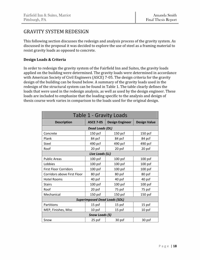
In order to redesign the gravity system of the Fairfield Inn and Suites, the gravity loads applied on the building were determined. The gravity loads were determined in accordance with American Society of Civil Engineers (ASCE) 7-05. The design criteria for the gravity design of the building can be found below. A summary of the gravity loads used in the redesign of the structural system can be found in Table 1. The table clearly defines the loads that were used in the redesign analysis, as well as used by the design engineer. These loads are included to emphasize that the loading specific to the analysis and design of thesis course work varies in comparison to the loads used for the original design.
Table 1 - Gravity Loads Description ASCE 7-05 Design Engineer Design Value
Dead Loads (DL)
Concrete 150 pcf 150 pcf 150 pcf
Plank 84 pcf 84 pcf 84 pcf
Steel 490 pcf 490 pcf 490 pcf
Roof 20 psf 20 psf 20 psf
Live Loads (LL)
Public Areas 100 psf 100 psf 100 psf
Lobbies 100 psf 100 psf 100 psf
First Floor Corridors 100 psf 100 psf 100 psf
Corridors above First Floor 80 psf 80 psf 80 psf
Hotel Rooms 40 psf 40 psf 40 psf
Stairs 100 psf 100 psf 100 psf
Roof 20 psf 75 psf 75 psf
Mechanical 150 psf 150 psf 150 psf
Superimposed Dead Loads (SDL)
Partitions 15 psf 15 psf 15 psf
MEP, Finishes, Misc 10 psf 15 psf 10 psf
Snow Loads (S)
Snow 25 psf 30 psf 30 psf

Fairfield Inn & Suites, Marriot
Pittsburgh, PA Amanda Smith
Final Thesis Report
P a g e | 19
Strength Design Criteria: ASCE 7-05 LRFD Load Combinations
1. 1.4D
2. 1.2D + 1.6L + 0.5(Lr or S)
3. 1.2D + 1.6Lr + 0.5L
The controlling load combination is 1.2D + 1.6L + 0.5Lr. The loads produced by this case
were used in designing the steel moment frame member sizes.
Serviceability Criteria: Deflection
Non-Composite:
Dead Load ………………………….l/360
Live Load …………………………...l/360
Total Load ………………………….l/240
Economy Criteria: Camber
Beams that do NOT camber: Beams that are less than 25ft Beams that requires less that ¾” of camber Beams in braced frames

Fairfield Inn & Suites, Marriot
Pittsburgh, PA Amanda Smith
Final Thesis Report
P a g e | 20
Design Process
Framing Plan
The structural redesign of the gravity system began with determining an initial framing
plan. It was possible to use the existing column locations for all interior and exterior
columns, as well as adding additional columns around the perimeter. The main effects of
the redesign will be that the columns in the building no longer only extend to the second
floor, but now extend the entire height of the building.
The plank floor system will still exist and now rest on steel girders rather than the load
bearing walls. Girders will now connect the columns making up the moment frames and the
perimeter of the building. The location of the interior moment frames was chosen because
this is where the interior load bearing masonry walls existed. A steel framing system
creates a thicker floor depth than having the 8” plank floor rest on load bearing walls. This
would affect the floor-to-ceiling height and ultimately result in a higher overall building
height. Even though the location of the building site would allow for the additional height,
placing the moment frames along the line of where the interior load bearing walls existed
than the floor-to-ceiling height would not be altered, and the overall building height would
remain the same.
Figure 4.1: Schematic Framing Plan
Fairfield Inn & Suites, Marriot
Pittsburgh, PA Amanda Smith
Final Thesis Report
P a g e | 21
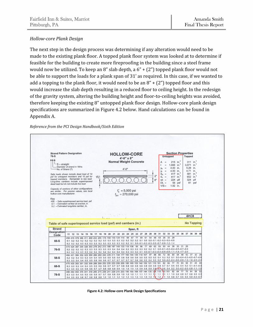
Hollow-core Plank Design
The next step in the design process was determining if any alteration would need to be
made to the existing plank floor. A topped plank floor system was looked at to determine if
feasible for the building to create more fireproofing in the building since a steel frame
would now be utilized. To keep an 8” slab depth, a 6” + (2”) topped plank floor would not
be able to support the loads for a plank span of 31’ as required. In this case, if we wanted to
add a topping to the plank floor, it would need to be an 8” + (2”) topped floor and this
would increase the slab depth resulting in a reduced floor to ceiling height. In the redesign
of the gravity system, altering the building height and floor-to-ceiling heights was avoided,
therefore keeping the existing 8” untopped plank floor design. Hollow-core plank design
specifications are summarized in Figure 4.2 below. Hand calculations can be found in
Appendix A.
Reference from the PCI Design Handbook/Sixth Edition
Figure 4.2: Hollow-core Plank Design Specifications
Fairfield Inn & Suites, Marriot
Pittsburgh, PA Amanda Smith
Final Thesis Report
P a g e | 22
Beam and Girder Design
With the plank floor system confirmed, the supporting steel framing members could be
designed for the given loads. Beams and girders were designed in accordance with Load
and Resistance Factor Design (LRFD) methods and the AISC Steel Construction Manual, 13th
edition. In accordance with ASCE 7-05, loads were multiplied by a load factor combination
that incorporated both the situations in which the loads would occur simultaneously at
their maximum level and the margins against which failure if the structure is measured.
Since the planks sit on the steel girders, there was no use for composite steel girders and
non-composite steel members were designed to support the floor system. The system of
hollow-core plank floors on structural steel frames is economical, easy to design, and fast to
erect.
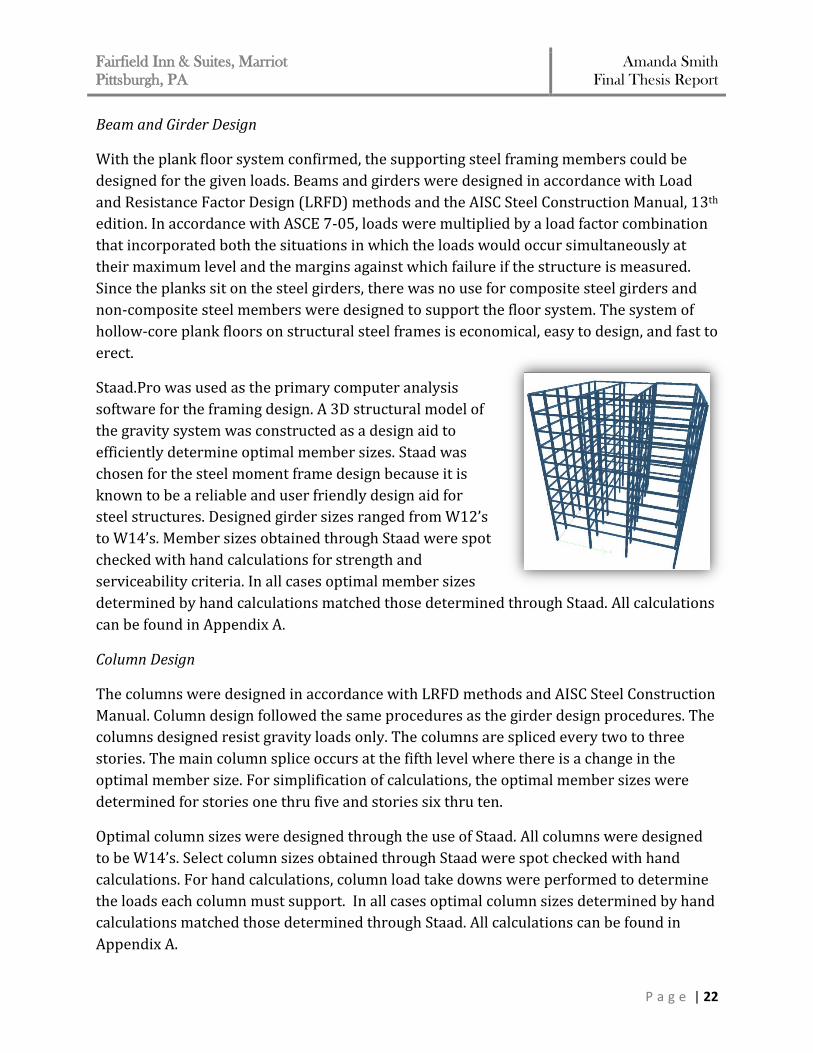
Staad.Pro was used as the primary computer analysis
software for the framing design. A 3D structural model of
the gravity system was constructed as a design aid to
efficiently determine optimal member sizes. Staad was
chosen for the steel moment frame design because it is
known to be a reliable and user friendly design aid for
steel structures. Designed girder sizes ranged from W12’s
to W14’s. Member sizes obtained through Staad were spot
checked with hand calculations for strength and
serviceability criteria. In all cases optimal member sizes
determined by hand calculations matched those determined through Staad. All calculations
can be found in Appendix A.
Column Design
The columns were designed in accordance with LRFD methods and AISC Steel Construction
Manual. Column design followed the same procedures as the girder design procedures. The
columns designed resist gravity loads only. The columns are spliced every two to three
stories. The main column splice occurs at the fifth level where there is a change in the
optimal member size. For simplification of calculations, the optimal member sizes were
determined for stories one thru five and stories six thru ten.
Optimal column sizes were designed through the use of Staad. All columns were designed
to be W14’s. Select column sizes obtained through Staad were spot checked with hand
calculations. For hand calculations, column load take downs were performed to determine
the loads each column must support. In all cases optimal column sizes determined by hand
calculations matched those determined through Staad. All calculations can be found in
Appendix A.
Fairfield Inn & Suites, Marriot
Pittsburgh, PA Amanda Smith
Final Thesis Report
P a g e | 23
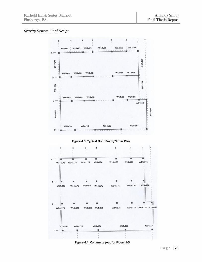
Gravity System Final Design
Figure 4.3: Typical Floor Beam/Girder Plan
Figure 4.4: Column Layout for Floors 1-5
Fairfield Inn & Suites, Marriot
Pittsburgh, PA Amanda Smith
Final Thesis Report
P a g e | 24
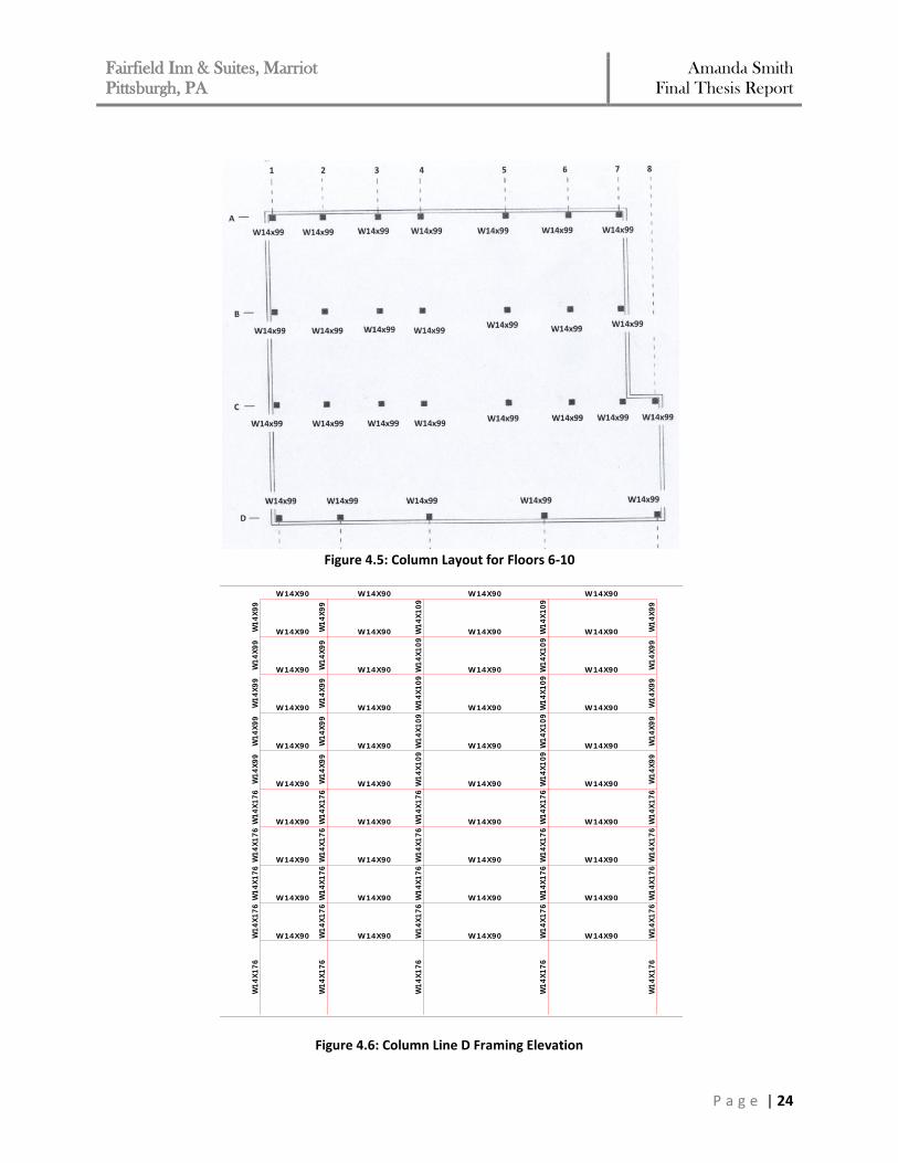
Figure 4.5: Column Layout for Floors 6-10
Figure 4.6: Column Line D Framing Elevation
W14X90
W1
4X
99
W14X90
W1
4X
99
W14X90
W1
4X
99
W1
4X
99
W1
4X
99
W1
4X
99
W14X90
W14X90W1
4X
99
W14X90
W14X90 W1
4X
99
W1
4X
17
6
W14X90
W14X90
W1
4X
99
W1
4X
17
6
W1
4X
10
9
W14X90
W1
4X
10
9
W14X90
W14X90
W14X90
W1
4X
17
6
W1
4X
10
9
W14X90
W14X90
W1
4X
17
6
W14X90 W14X90
W14X90
W1
4X
17
6W
14
X1
76
W1
4X
17
6
W14X90
W1
4X
17
6
W14X90
W1
4X
17
6
W1
4X
17
6
W1
4X
99
W1
4X
10
9W
14
X1
76
W14X90
W1
4X
99
W1
4X
17
6
W14X90
W1
4X
99
W1
4X
17
6
W14X90
W1
4X
10
9
W1
4X
17
6
W14X90
W1
4X
17
6
W1
4X
10
9
W14X90
W1
4X
17
6
W14X90
W1
4X
17
6
W14X90
W14X90
W1
4X
99
W14X90
W1
4X
17
6
W14X90
W1
4X
99
W14X90
W1
4X
17
6
W14X90
W1
4X
10
9
W1
4X
17
6
W1
4X
17
6
W14X90
W1
4X
17
6
W1
4X
10
9
W1
4X
17
6
W14X90
W14X90
W1
4X
10
9
W14X90
W1
4X
99
W14X90
W1
4X
10
9
W14X90
W1
4X
17
6
W1
4X
17
6
W14X90
W14X90
Load 1
Fairfield Inn & Suites, Marriot
Pittsburgh, PA Amanda Smith
Final Thesis Report
P a g e | 25
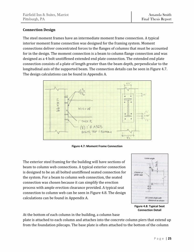
Connection Design
The steel moment frames have an intermediate moment frame connection. A typical
interior moment frame connection was designed for the framing system. Moment
connections deliver concentrated forces to the flanges of columns that must be accounted
for in the design. The moment connection is a beam to column flange connection and was
designed as a 4 bolt unstiffened extended end plate connection. The extended end plate
connection consists of a plate of length greater than the beam depth, perpendicular to the
longitudinal axis of the supported beam. The connection details can be seen in Figure 4.7.
The design calculations can be found in Appendix A.
Figure 4.7: Moment Frame Connection
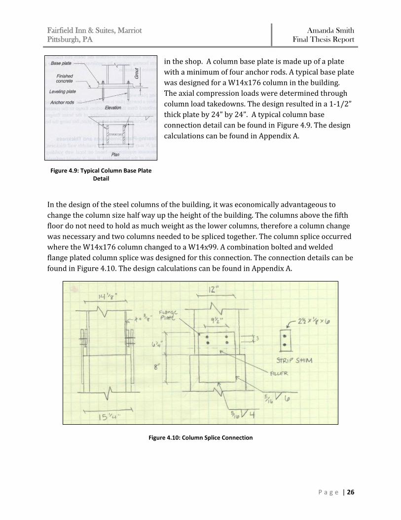
The exterior steel framing for the building will have sections of
beam to column web connections. A typical exterior connection
is designed to be an all bolted unstiffened seated connection for
the system. For a beam to column web connection, the seated
connection was chosen because it can simplify the erection
process with ample erection clearance provided. A typical seat
connection to column web can be seen in Figure 4.8. The design
calculations can be found in Appendix A.
At the bottom of each column in the building, a column base
plate is attached to each column and attaches into the concrete column piers that extend up
from the foundation pilecaps. The base plate is often attached to the bottom of the column
Figure 4.8: Typical Seat Connection Detail
Fairfield Inn & Suites, Marriot
Pittsburgh, PA Amanda Smith
Final Thesis Report
P a g e | 26
in the shop. A column base plate is made up of a plate
with a minimum of four anchor rods. A typical base plate
was designed for a W14x176 column in the building.
The axial compression loads were determined through
column load takedowns. The design resulted in a 1-1/2”
thick plate by 24” by 24”. A typical column base
connection detail can be found in Figure 4.9. The design
calculations can be found in Appendix A.
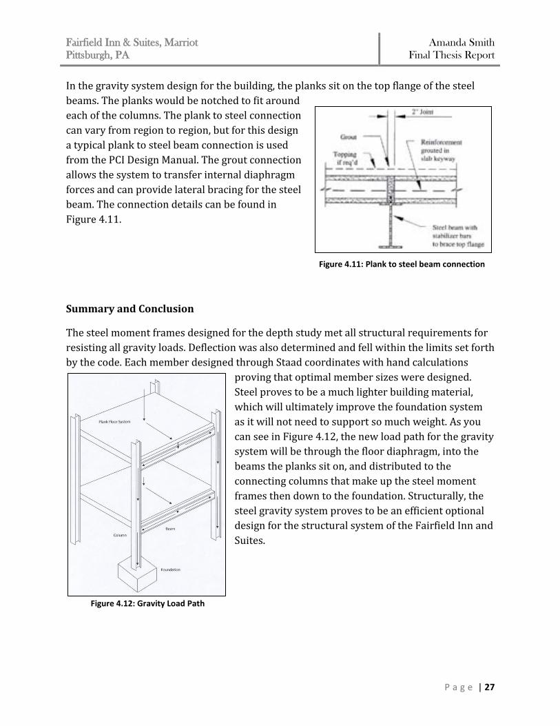
In the design of the steel columns of the building, it was economically advantageous to
change the column size half way up the height of the building. The columns above the fifth
floor do not need to hold as much weight as the lower columns, therefore a column change
was necessary and two columns needed to be spliced together. The column splice occurred
where the W14x176 column changed to a W14x99. A combination bolted and welded
flange plated column splice was designed for this connection. The connection details can be
found in Figure 4.10. The design calculations can be found in Appendix A.
Figure 4.10: Column Splice Connection
Figure 4.9: Typical Column Base Plate Detail
Fairfield Inn & Suites, Marriot
Pittsburgh, PA Amanda Smith
Final Thesis Report
P a g e | 27
In the gravity system design for the building, the planks sit on the top flange of the steel
beams. The planks would be notched to fit around
each of the columns. The plank to steel connection
can vary from region to region, but for this design
a typical plank to steel beam connection is used
from the PCI Design Manual. The grout connection
allows the system to transfer internal diaphragm
forces and can provide lateral bracing for the steel
beam. The connection details can be found in
Figure 4.11.
Summary and Conclusion
The steel moment frames designed for the depth study met all structural requirements for
resisting all gravity loads. Deflection was also determined and fell within the limits set forth
by the code. Each member designed through Staad coordinates with hand calculations
proving that optimal member sizes were designed.
Steel proves to be a much lighter building material,
which will ultimately improve the foundation system
as it will not need to support so much weight. As you
can see in Figure 4.12, the new load path for the gravity
system will be through the floor diaphragm, into the
beams the planks sit on, and distributed to the
connecting columns that make up the steel moment
frames then down to the foundation. Structurally, the
steel gravity system proves to be an efficient optional
design for the structural system of the Fairfield Inn and
Suites.
Figure 4.11: Plank to steel beam connection
Figure 4.12: Gravity Load Path
Fairfield Inn & Suites, Marriot
Pittsburgh, PA Amanda Smith
Final Thesis Report
P a g e | 28
LATERAL FORCE RESISTING SYSTEM REDESIGN
This following section discusses the redesign and analysis process of the lateral force resisting system. As discussed in the proposal it was decided to keep shear walls as the lateral system, but to reduce the number of walls used in the system compared to the original design. Design Loads & Criteria
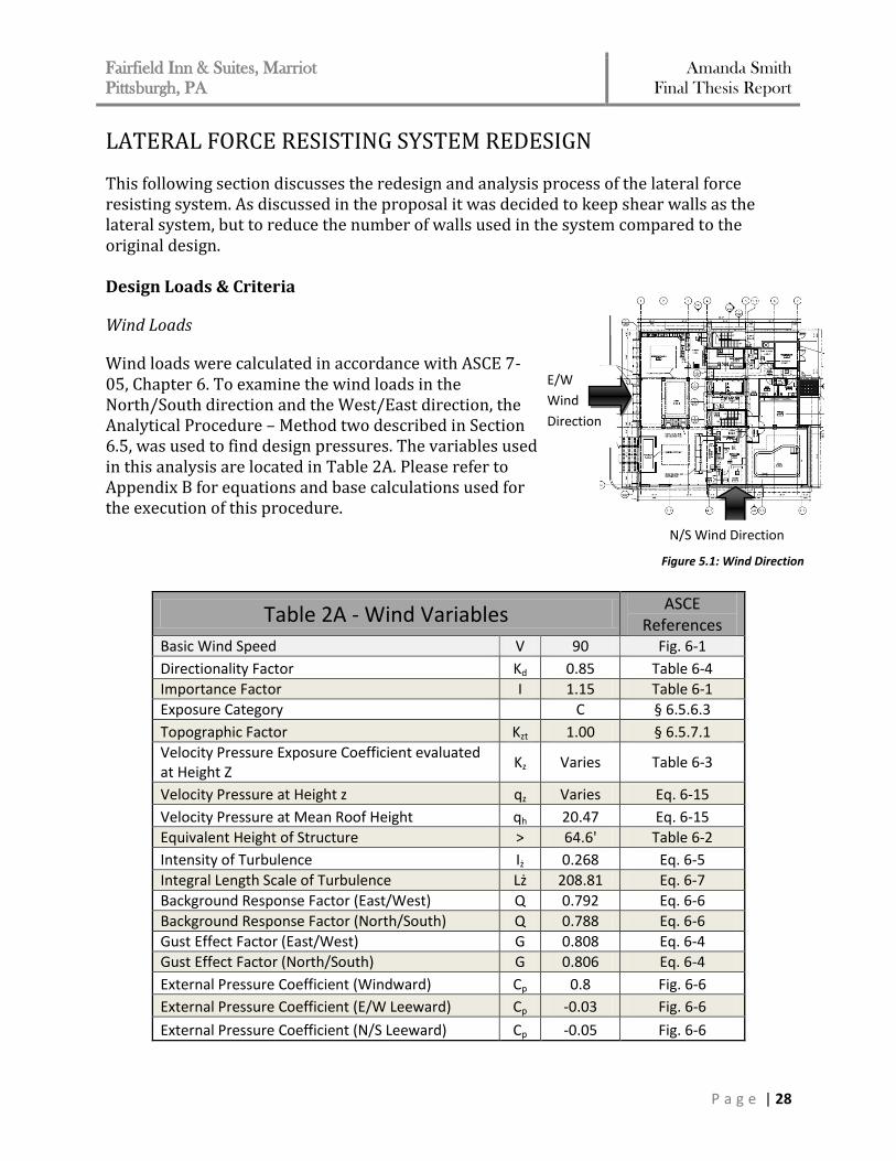
Wind Loads
Wind loads were calculated in accordance with ASCE 7-05, Chapter 6. To examine the wind loads in the North/South direction and the West/East direction, the Analytical Procedure – Method two described in Section 6.5, was used to find design pressures. The variables used in this analysis are located in Table 2A. Please refer to Appendix B for equations and base calculations used for the execution of this procedure.
Table 2A - Wind Variables ASCE
References Basic Wind Speed V 90 Fig. 6-1
Directionality Factor Kd 0.85 Table 6-4
Importance Factor I 1.15 Table 6-1
Exposure Category C § 6.5.6.3
Topographic Factor Kzt 1.00 § 6.5.7.1
Velocity Pressure Exposure Coefficient evaluated at Height Z
Kz Varies Table 6-3
Velocity Pressure at Height z qz Varies Eq. 6-15
Velocity Pressure at Mean Roof Height qh 20.47 Eq. 6-15
Equivalent Height of Structure > 64.6' Table 6-2
Intensity of Turbulence Iż 0.268 Eq. 6-5
Integral Length Scale of Turbulence Lż 208.81 Eq. 6-7
Background Response Factor (East/West) Q 0.792 Eq. 6-6
Background Response Factor (North/South) Q 0.788 Eq. 6-6
Gust Effect Factor (East/West) G 0.808 Eq. 6-4
Gust Effect Factor (North/South) G 0.806 Eq. 6-4
External Pressure Coefficient (Windward) Cp 0.8 Fig. 6-6
External Pressure Coefficient (E/W Leeward) Cp -0.03 Fig. 6-6
External Pressure Coefficient (N/S Leeward) Cp -0.05 Fig. 6-6
Figure 5.1: Wind Direction
E/W
Wind
Direction
N/S Wind Direction
Fairfield Inn & Suites, Marriot
Pittsburgh, PA Amanda Smith
Final Thesis Report
P a g e | 29
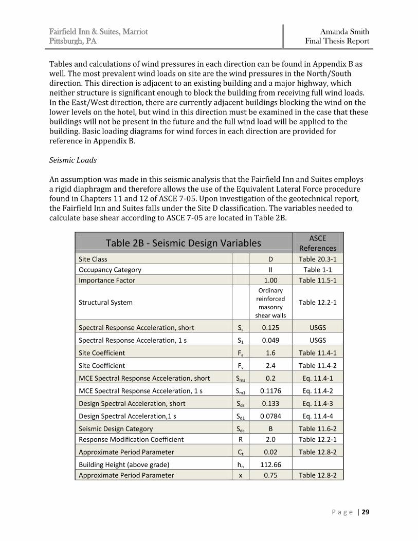
Tables and calculations of wind pressures in each direction can be found in Appendix B as well. The most prevalent wind loads on site are the wind pressures in the North/South direction. This direction is adjacent to an existing building and a major highway, which neither structure is significant enough to block the building from receiving full wind loads. In the East/West direction, there are currently adjacent buildings blocking the wind on the lower levels on the hotel, but wind in this direction must be examined in the case that these buildings will not be present in the future and the full wind load will be applied to the building. Basic loading diagrams for wind forces in each direction are provided for reference in Appendix B. Seismic Loads An assumption was made in this seismic analysis that the Fairfield Inn and Suites employs a rigid diaphragm and therefore allows the use of the Equivalent Lateral Force procedure found in Chapters 11 and 12 of ASCE 7-05. Upon investigation of the geotechnical report, the Fairfield Inn and Suites falls under the Site D classification. The variables needed to calculate base shear according to ASCE 7-05 are located in Table 2B.
Table 2B - Seismic Design Variables ASCE
References
Site Class D Table 20.3-1
Occupancy Category II Table 1-1
Importance Factor 1.00 Table 11.5-1
Structural System
Ordinary reinforced masonry
shear walls
Table 12.2-1
Spectral Response Acceleration, short Ss 0.125 USGS
Spectral Response Acceleration, 1 s S1 0.049 USGS
Site Coefficient Fa 1.6 Table 11.4-1
Site Coefficient Fv 2.4 Table 11.4-2
MCE Spectral Response Acceleration, short Sms 0.2 Eq. 11.4-1
MCE Spectral Response Acceleration, 1 s Sm1 0.1176 Eq. 11.4-2
Design Spectral Acceleration, short Sds 0.133 Eq. 11.4-3
Design Spectral Acceleration,1 s Sd1 0.0784 Eq. 11.4-4
Seismic Design Category Sdc B Table 11.6-2
Response Modification Coefficient R 2.0 Table 12.2-1
Approximate Period Parameter Ct 0.02 Table 12.8-2
Building Height (above grade) hn 112.66
Approximate Period Parameter x 0.75 Table 12.8-2
Fairfield Inn & Suites, Marriot
Pittsburgh, PA Amanda Smith
Final Thesis Report
P a g e | 30
Calculated Period Upper Limit Coefficient Cu 1.70 Table 12.8-1
Approximate Fundamental Period Ta 0.692 Eq. 12.8-7
Fundamental Period T 1.17 Sec. 12.8.2
Long Period Transition Period TL 12 Fig. 22-15
Seismic Response Coefficient Cs 0.034 Eq. 12.8-2
Structural Period Exponent k 1.335 Sec. 12.8.3
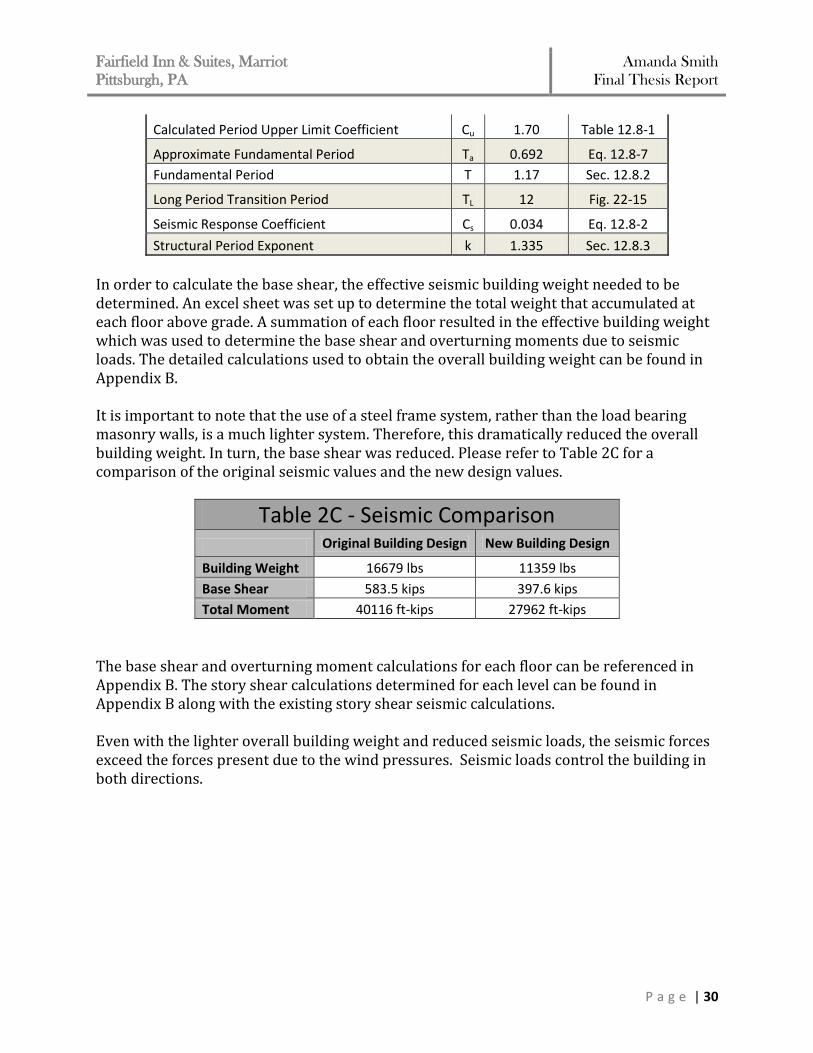
In order to calculate the base shear, the effective seismic building weight needed to be determined. An excel sheet was set up to determine the total weight that accumulated at each floor above grade. A summation of each floor resulted in the effective building weight which was used to determine the base shear and overturning moments due to seismic loads. The detailed calculations used to obtain the overall building weight can be found in Appendix B. It is important to note that the use of a steel frame system, rather than the load bearing masonry walls, is a much lighter system. Therefore, this dramatically reduced the overall building weight. In turn, the base shear was reduced. Please refer to Table 2C for a comparison of the original seismic values and the new design values.
Table 2C - Seismic Comparison Original Building Design New Building Design
Building Weight 16679 lbs 11359 lbs
Base Shear 583.5 kips 397.6 kips
Total Moment 40116 ft-kips 27962 ft-kips
The base shear and overturning moment calculations for each floor can be referenced in Appendix B. The story shear calculations determined for each level can be found in Appendix B along with the existing story shear seismic calculations. Even with the lighter overall building weight and reduced seismic loads, the seismic forces exceed the forces present due to the wind pressures. Seismic loads control the building in both directions.
Fairfield Inn & Suites, Marriot
Pittsburgh, PA Amanda Smith
Final Thesis Report
P a g e | 31
Load Combinations The list below shows the various load cases according to ASCE-07 section 2.3 for factored loads using strength design and from the International Building Code, 2006 edition. These were the load cases used in the analysis of the lateral system for this report. 1.4D 1.2D +1.6L +0.5Lr 1.2D +1.6W +1.0L +0.5Lr 1.2D + 1.0E + 0.5L 0.9D + 1.6W 0.9D + 1.0E The controlling load combination in each direction is 0.9D + 1.0E. Drift Criteria The following allowable drift criteria that will be used to check deflection for the redesign of the buildings lateral system will be in accordance with the International Building Code, 2006 edition.
(Allowable Building Drift) Δwind = H/400
(Allowable Story Drift) Δseismic = 0.015Hsx
Since the seismic loads control in both directions, the story drift will be governed by the allowable seismic drift equation. Material Properties The material strengths for the lateral system redesign are as follows: Normal Weight Concrete
f’c = 8000 psi (for walls supporting ground to 4th floor) f’c = 5000 psi (for walls supporting 5th floor and above) Ec = 5700 kis
CMU Block
f’m = 1500 psi Reinforcing Steel
fy = 60 ksi Es = 29000 ksi
Fairfield Inn & Suites, Marriot
Pittsburgh, PA Amanda Smith
Final Thesis Report
P a g e | 32
Design Process
Modified Shear Wall Layout
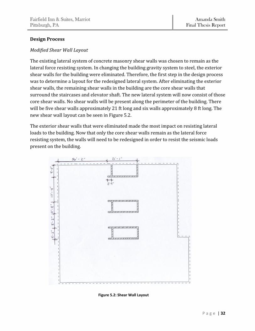
The existing lateral system of concrete masonry shear walls was chosen to remain as the
lateral force resisting system. In changing the building gravity system to steel, the exterior
shear walls for the building were eliminated. Therefore, the first step in the design process
was to determine a layout for the redesigned lateral system. After eliminating the exterior
shear walls, the remaining shear walls in the building are the core shear walls that
surround the staircases and elevator shaft. The new lateral system will now consist of those
core shear walls. No shear walls will be present along the perimeter of the building. There
will be five shear walls approximately 21 ft long and six walls approximately 8 ft long. The
new shear wall layout can be seen in Figure 5.2.
The exterior shear walls that were eliminated made the most impact on resisting lateral
loads to the building. Now that only the core shear walls remain as the lateral force
resisting system, the walls will need to be redesigned in order to resist the seismic loads
present on the building.
Figure 5.2: Shear Wall Layout
Fairfield Inn & Suites, Marriot
Pittsburgh, PA Amanda Smith
Final Thesis Report
P a g e | 33
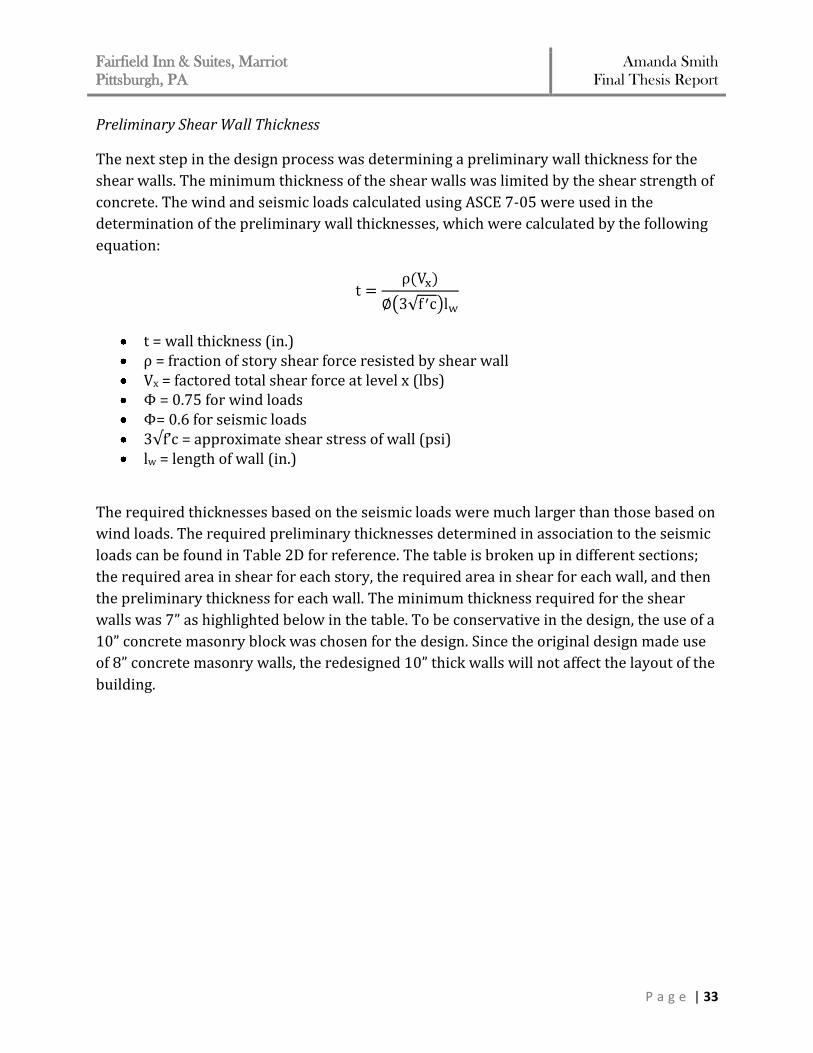
Preliminary Shear Wall Thickness
The next step in the design process was determining a preliminary wall thickness for the
shear walls. The minimum thickness of the shear walls was limited by the shear strength of
concrete. The wind and seismic loads calculated using ASCE 7-05 were used in the
determination of the preliminary wall thicknesses, which were calculated by the following
equation:
t = wall thickness (in.) ρ = fraction of story shear force resisted by shear wall Vx = factored total shear force at level x (lbs) Φ = 0.75 for wind loads Φ= 0.6 for seismic loads 3√f’c = approximate shear stress of wall (psi) lw = length of wall (in.)
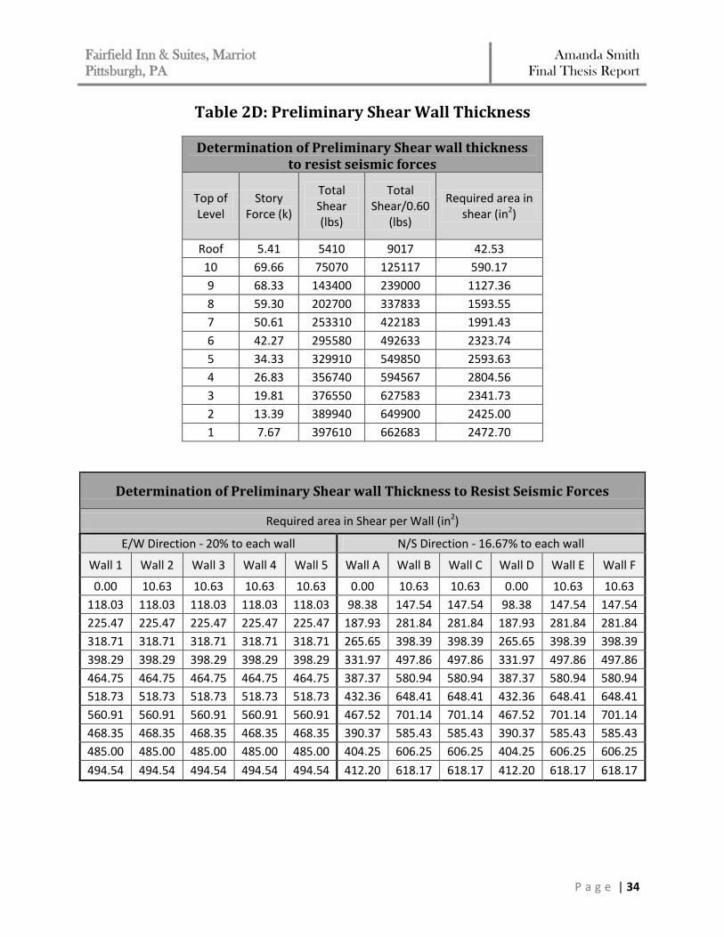
The required thicknesses based on the seismic loads were much larger than those based on
wind loads. The required preliminary thicknesses determined in association to the seismic
loads can be found in Table 2D for reference. The table is broken up in different sections;
the required area in shear for each story, the required area in shear for each wall, and then
the preliminary thickness for each wall. The minimum thickness required for the shear
walls was 7” as highlighted below in the table. To be conservative in the design, the use of a
10” concrete masonry block was chosen for the design. Since the original design made use
of 8” concrete masonry walls, the redesigned 10” thick walls will not affect the layout of the
building.
Fairfield Inn & Suites, Marriot
Pittsburgh, PA Amanda Smith
Final Thesis Report
P a g e | 34
Table 2D: Preliminary Shear Wall Thickness
Determination of Preliminary Shear wall thickness to resist seismic forces
Top of Level
Story Force (k)
Total Shear (lbs)
Total Shear/0.60
(lbs)
Required area in shear (in2)
Roof 5.41 5410 9017 42.53
10 69.66 75070 125117 590.17
9 68.33 143400 239000 1127.36
8 59.30 202700 337833 1593.55
7 50.61 253310 422183 1991.43
6 42.27 295580 492633 2323.74
5 34.33 329910 549850 2593.63
4 26.83 356740 594567 2804.56
3 19.81 376550 627583 2341.73
2 13.39 389940 649900 2425.00
1 7.67 397610 662683 2472.70
Determination of Preliminary Shear wall Thickness to Resist Seismic Forces
Required area in Shear per Wall (in2)
E/W Direction - 20% to each wall N/S Direction - 16.67% to each wall
Wall 1 Wall 2 Wall 3 Wall 4 Wall 5 Wall A Wall B Wall C Wall D Wall E Wall F
0.00 10.63 10.63 10.63 10.63 0.00 10.63 10.63 0.00 10.63 10.63
118.03 118.03 118.03 118.03 118.03 98.38 147.54 147.54 98.38 147.54 147.54
225.47 225.47 225.47 225.47 225.47 187.93 281.84 281.84 187.93 281.84 281.84
318.71 318.71 318.71 318.71 318.71 265.65 398.39 398.39 265.65 398.39 398.39
398.29 398.29 398.29 398.29 398.29 331.97 497.86 497.86 331.97 497.86 497.86
464.75 464.75 464.75 464.75 464.75 387.37 580.94 580.94 387.37 580.94 580.94
518.73 518.73 518.73 518.73 518.73 432.36 648.41 648.41 432.36 648.41 648.41
560.91 560.91 560.91 560.91 560.91 467.52 701.14 701.14 467.52 701.14 701.14
468.35 468.35 468.35 468.35 468.35 390.37 585.43 585.43 390.37 585.43 585.43
485.00 485.00 485.00 485.00 485.00 404.25 606.25 606.25 404.25 606.25 606.25
494.54 494.54 494.54 494.54 494.54 412.20 618.17 618.17 412.20 618.17 618.17
Fairfield Inn & Suites, Marriot
Pittsburgh, PA Amanda Smith
Final Thesis Report
P a g e | 35
Determination of Preliminary Shear wall Thickness to Resist Seismic Forces
Preliminary Thickness (in)
E/W Direction N/S Direction
Wall 1 Wall 2 Wall 3 Wall 4 Wall 5 Wall A Wall B Wall C Wall D Wall E Wall F
0.000 0.043 0.043 0.041 0.041 0.000 0.111 0.097 0.000 0.111 0.097
0.457 0.480 0.480 0.457 0.457 0.965 1.537 1.341 0.965 1.537 1.341
0.874 0.917 0.917 0.874 0.874 1.842 2.936 2.562 1.842 2.936 2.562
1.235 1.296 1.296 1.235 1.235 2.604 4.150 3.622 2.604 4.150 3.622
1.544 1.619 1.619 1.544 1.544 3.255 5.186 4.526 3.255 5.186 4.526
1.801 1.889 1.889 1.801 1.801 3.798 6.051 5.281 3.798 6.051 5.281
2.011 2.109 2.109 2.011 2.011 4.239 6.754 5.895 4.239 6.754 5.895
2.174 2.280 2.280 2.174 2.174 4.584 7.304 6.374 4.584 7.304 6.374
1.815 1.904 1.904 1.815 1.815 3.827 6.098 5.322 3.827 6.098 5.322
1.880 1.972 1.972 1.880 1.880 3.963 6.315 5.511 3.963 6.315 5.511
1.917 2.010 2.010 1.917 1.917 4.041 6.439 5.620 4.041 6.439 5.620
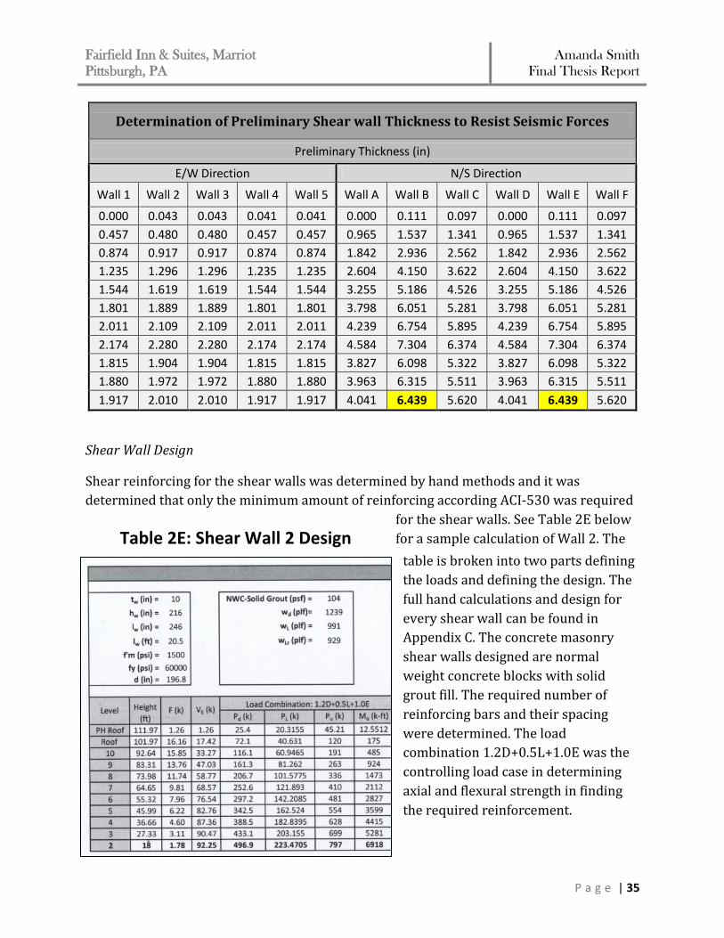
Shear Wall Design
Shear reinforcing for the shear walls was determined by hand methods and it was
determined that only the minimum amount of reinforcing according ACI-530 was required
for the shear walls. See Table 2E below
for a sample calculation of Wall 2. The
table is broken into two parts defining
the loads and defining the design. The
full hand calculations and design for
every shear wall can be found in
Appendix C. The concrete masonry
shear walls designed are normal
weight concrete blocks with solid
grout fill. The required number of
reinforcing bars and their spacing
were determined. The load
combination 1.2D+0.5L+1.0E was the
controlling load case in determining
axial and flexural strength in finding
the required reinforcement.
Table 2E: Shear Wall 2 Design
Fairfield Inn & Suites, Marriot
Pittsburgh, PA Amanda Smith
Final Thesis Report
P a g e | 36
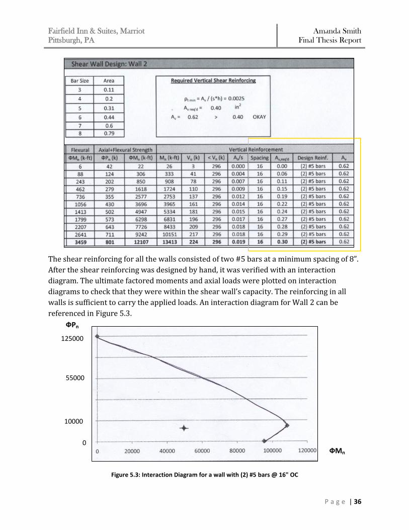
The shear reinforcing for all the walls consisted of two #5 bars at a minimum spacing of 8”.
After the shear reinforcing was designed by hand, it was verified with an interaction
diagram. The ultimate factored moments and axial loads were plotted on interaction
diagrams to check that they were within the shear wall’s capacity. The reinforcing in all
walls is sufficient to carry the applied loads. An interaction diagram for Wall 2 can be
referenced in Figure 5.3.
Figure 5.3: Interaction Diagram for a wall with (2) #5 bars @ 16" OC
125000
10000
0
55000
ФPn
ФMn
Fairfield Inn & Suites, Marriot
Pittsburgh, PA Amanda Smith
Final Thesis Report
P a g e | 37
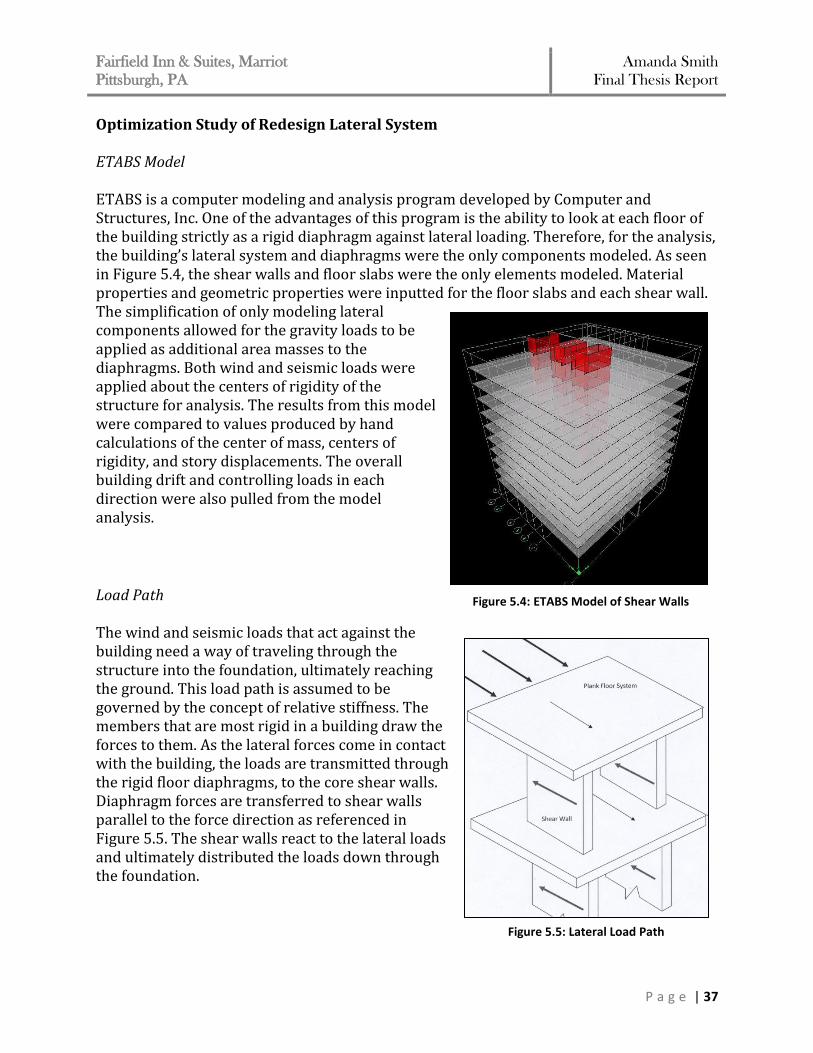
Optimization Study of Redesign Lateral System ETABS Model ETABS is a computer modeling and analysis program developed by Computer and Structures, Inc. One of the advantages of this program is the ability to look at each floor of the building strictly as a rigid diaphragm against lateral loading. Therefore, for the analysis, the building’s lateral system and diaphragms were the only components modeled. As seen in Figure 5.4, the shear walls and floor slabs were the only elements modeled. Material properties and geometric properties were inputted for the floor slabs and each shear wall. The simplification of only modeling lateral components allowed for the gravity loads to be applied as additional area masses to the diaphragms. Both wind and seismic loads were applied about the centers of rigidity of the structure for analysis. The results from this model were compared to values produced by hand calculations of the center of mass, centers of rigidity, and story displacements. The overall building drift and controlling loads in each direction were also pulled from the model analysis.
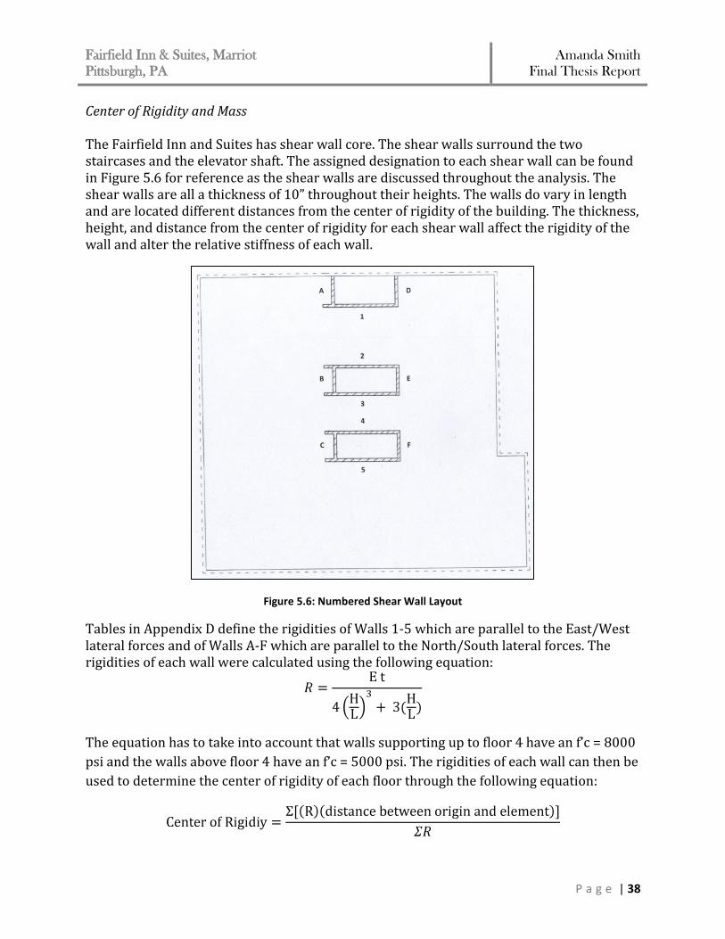
Load Path The wind and seismic loads that act against the building need a way of traveling through the structure into the foundation, ultimately reaching the ground. This load path is assumed to be governed by the concept of relative stiffness. The members that are most rigid in a building draw the forces to them. As the lateral forces come in contact with the building, the loads are transmitted through the rigid floor diaphragms, to the core shear walls. Diaphragm forces are transferred to shear walls parallel to the force direction as referenced in Figure 5.5. The shear walls react to the lateral loads and ultimately distributed the loads down through the foundation.
Figure 5.4: ETABS Model of Shear Walls
Figure 5.5: Lateral Load Path
Fairfield Inn & Suites, Marriot
Pittsburgh, PA Amanda Smith
Final Thesis Report
P a g e | 38
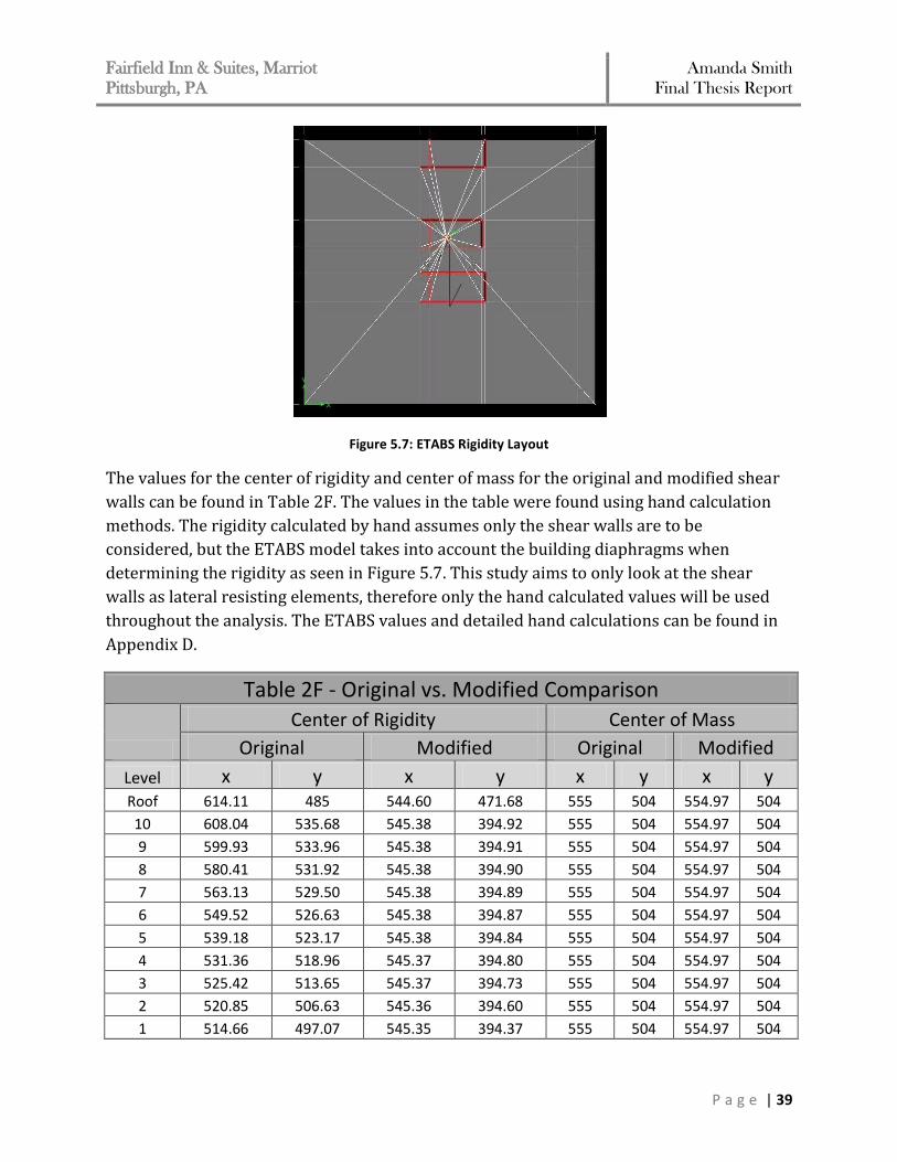
Center of Rigidity and Mass The Fairfield Inn and Suites has shear wall core. The shear walls surround the two staircases and the elevator shaft. The assigned designation to each shear wall can be found in Figure 5.6 for reference as the shear walls are discussed throughout the analysis. The shear walls are all a thickness of 10” throughout their heights. The walls do vary in length and are located different distances from the center of rigidity of the building. The thickness, height, and distance from the center of rigidity for each shear wall affect the rigidity of the wall and alter the relative stiffness of each wall.
Figure 5.6: Numbered Shear Wall Layout
Tables in Appendix D define the rigidities of Walls 1-5 which are parallel to the East/West lateral forces and of Walls A-F which are parallel to the North/South lateral forces. The rigidities of each wall were calculated using the following equation:
The equation has to take into account that walls supporting up to floor 4 have an f’c = 8000
psi and the walls above floor 4 have an f’c = 5000 psi. The rigidities of each wall can then be
used to determine the center of rigidity of each floor through the following equation:
Fairfield Inn & Suites, Marriot
Pittsburgh, PA Amanda Smith
Final Thesis Report
P a g e | 39
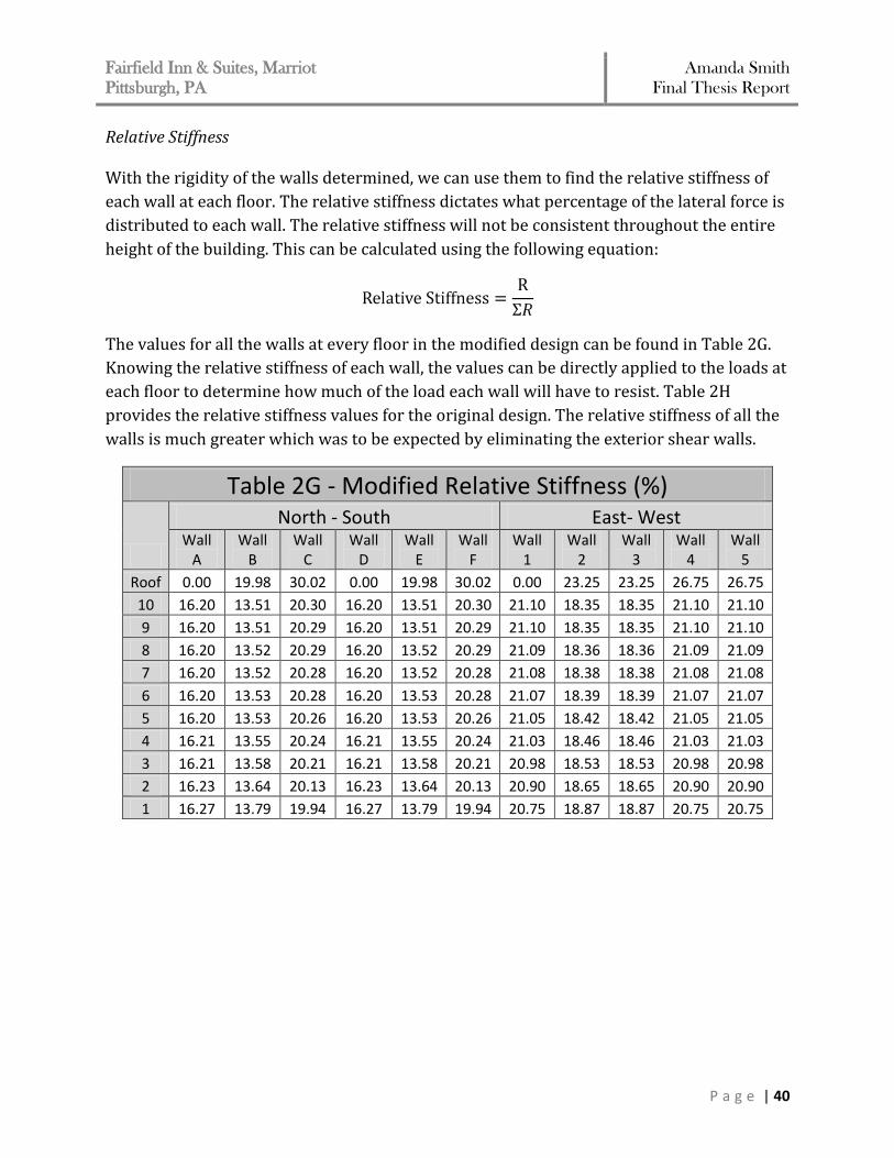
Figure 5.7: ETABS Rigidity Layout
The values for the center of rigidity and center of mass for the original and modified shear
walls can be found in Table 2F. The values in the table were found using hand calculation
methods. The rigidity calculated by hand assumes only the shear walls are to be
considered, but the ETABS model takes into account the building diaphragms when
determining the rigidity as seen in Figure 5.7. This study aims to only look at the shear
walls as lateral resisting elements, therefore only the hand calculated values will be used
throughout the analysis. The ETABS values and detailed hand calculations can be found in
Appendix D.
Table 2F - Original vs. Modified Comparison
Center of Rigidity Center of Mass
Original Modified Original Modified
Level x y x y x y x y Roof 614.11 485 544.60 471.68 555 504 554.97 504
10 608.04 535.68 545.38 394.92 555 504 554.97 504
9 599.93 533.96 545.38 394.91 555 504 554.97 504
8 580.41 531.92 545.38 394.90 555 504 554.97 504
7 563.13 529.50 545.38 394.89 555 504 554.97 504
6 549.52 526.63 545.38 394.87 555 504 554.97 504
5 539.18 523.17 545.38 394.84 555 504 554.97 504
4 531.36 518.96 545.37 394.80 555 504 554.97 504
3 525.42 513.65 545.37 394.73 555 504 554.97 504
2 520.85 506.63 545.36 394.60 555 504 554.97 504
1 514.66 497.07 545.35 394.37 555 504 554.97 504
Fairfield Inn & Suites, Marriot
Pittsburgh, PA Amanda Smith
Final Thesis Report
P a g e | 40
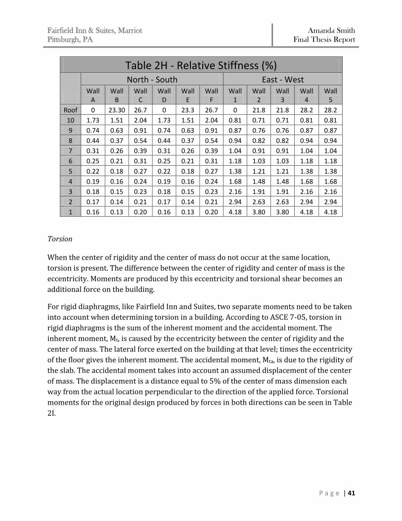
Relative Stiffness With the rigidity of the walls determined, we can use them to find the relative stiffness of
each wall at each floor. The relative stiffness dictates what percentage of the lateral force is
distributed to each wall. The relative stiffness will not be consistent throughout the entire
height of the building. This can be calculated using the following equation:
The values for all the walls at every floor in the modified design can be found in Table 2G.
Knowing the relative stiffness of each wall, the values can be directly applied to the loads at
each floor to determine how much of the load each wall will have to resist. Table 2H
provides the relative stiffness values for the original design. The relative stiffness of all the
walls is much greater which was to be expected by eliminating the exterior shear walls.
Table 2G - Modified Relative Stiffness (%)
North - South East- West Wall
A Wall
B Wall
C Wall
D Wall
E Wall
F Wall
1 Wall
2 Wall
3 Wall
4 Wall
5
Roof 0.00 19.98 30.02 0.00 19.98 30.02 0.00 23.25 23.25 26.75 26.75
10 16.20 13.51 20.30 16.20 13.51 20.30 21.10 18.35 18.35 21.10 21.10
9 16.20 13.51 20.29 16.20 13.51 20.29 21.10 18.35 18.35 21.10 21.10
8 16.20 13.52 20.29 16.20 13.52 20.29 21.09 18.36 18.36 21.09 21.09
7 16.20 13.52 20.28 16.20 13.52 20.28 21.08 18.38 18.38 21.08 21.08
6 16.20 13.53 20.28 16.20 13.53 20.28 21.07 18.39 18.39 21.07 21.07
5 16.20 13.53 20.26 16.20 13.53 20.26 21.05 18.42 18.42 21.05 21.05
4 16.21 13.55 20.24 16.21 13.55 20.24 21.03 18.46 18.46 21.03 21.03
3 16.21 13.58 20.21 16.21 13.58 20.21 20.98 18.53 18.53 20.98 20.98
2 16.23 13.64 20.13 16.23 13.64 20.13 20.90 18.65 18.65 20.90 20.90
1 16.27 13.79 19.94 16.27 13.79 19.94 20.75 18.87 18.87 20.75 20.75
Fairfield Inn & Suites, Marriot
Pittsburgh, PA Amanda Smith
Final Thesis Report
P a g e | 41
Table 2H - Relative Stiffness (%)
North - South East - West Wall
A Wall
B Wall
C Wall
D Wall
E Wall
F Wall
1 Wall
2 Wall
3 Wall
4 Wall
5
Roof 0 23.30 26.7 0 23.3 26.7 0 21.8 21.8 28.2 28.2
10 1.73 1.51 2.04 1.73 1.51 2.04 0.81 0.71 0.71 0.81 0.81
9 0.74 0.63 0.91 0.74 0.63 0.91 0.87 0.76 0.76 0.87 0.87
8 0.44 0.37 0.54 0.44 0.37 0.54 0.94 0.82 0.82 0.94 0.94
7 0.31 0.26 0.39 0.31 0.26 0.39 1.04 0.91 0.91 1.04 1.04
6 0.25 0.21 0.31 0.25 0.21 0.31 1.18 1.03 1.03 1.18 1.18
5 0.22 0.18 0.27 0.22 0.18 0.27 1.38 1.21 1.21 1.38 1.38
4 0.19 0.16 0.24 0.19 0.16 0.24 1.68 1.48 1.48 1.68 1.68
3 0.18 0.15 0.23 0.18 0.15 0.23 2.16 1.91 1.91 2.16 2.16
2 0.17 0.14 0.21 0.17 0.14 0.21 2.94 2.63 2.63 2.94 2.94
1 0.16 0.13 0.20 0.16 0.13 0.20 4.18 3.80 3.80 4.18 4.18
Torsion When the center of rigidity and the center of mass do not occur at the same location,
torsion is present. The difference between the center of rigidity and center of mass is the
eccentricity. Moments are produced by this eccentricity and torsional shear becomes an
additional force on the building.
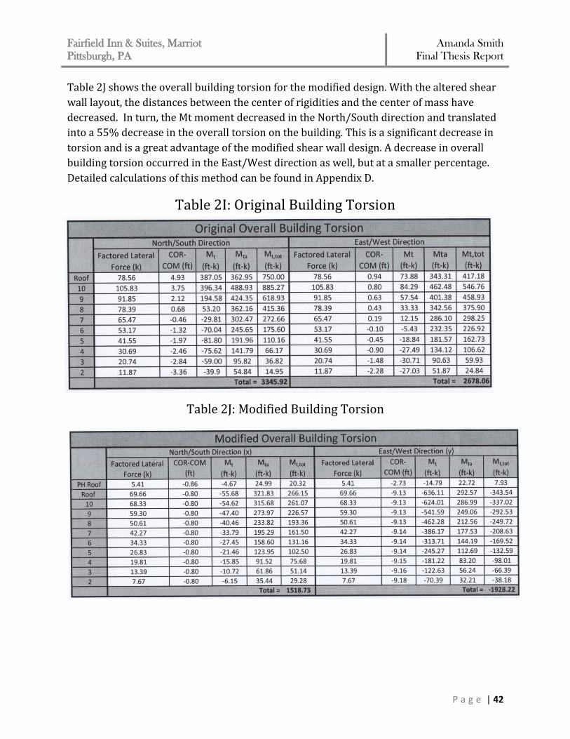
For rigid diaphragms, like Fairfield Inn and Suites, two separate moments need to be taken
into account when determining torsion in a building. According to ASCE 7-05, torsion in
rigid diaphragms is the sum of the inherent moment and the accidental moment. The
inherent moment, Mt, is caused by the eccentricity between the center of rigidity and the
center of mass. The lateral force exerted on the building at that level; times the eccentricity
of the floor gives the inherent moment. The accidental moment, Mta, is due to the rigidity of
the slab. The accidental moment takes into account an assumed displacement of the center
of mass. The displacement is a distance equal to 5% of the center of mass dimension each
way from the actual location perpendicular to the direction of the applied force. Torsional
moments for the original design produced by forces in both directions can be seen in Table
2I.
Fairfield Inn & Suites, Marriot
Pittsburgh, PA Amanda Smith
Final Thesis Report
P a g e | 42
Table 2J shows the overall building torsion for the modified design. With the altered shear
wall layout, the distances between the center of rigidities and the center of mass have
decreased. In turn, the Mt moment decreased in the North/South direction and translated
into a 55% decrease in the overall torsion on the building. This is a significant decrease in
torsion and is a great advantage of the modified shear wall design. A decrease in overall
building torsion occurred in the East/West direction as well, but at a smaller percentage.
Detailed calculations of this method can be found in Appendix D.
Table 2I: Original Building Torsion
Table 2J: Modified Building Torsion
Fairfield Inn & Suites, Marriot
Pittsburgh, PA Amanda Smith
Final Thesis Report
P a g e | 43
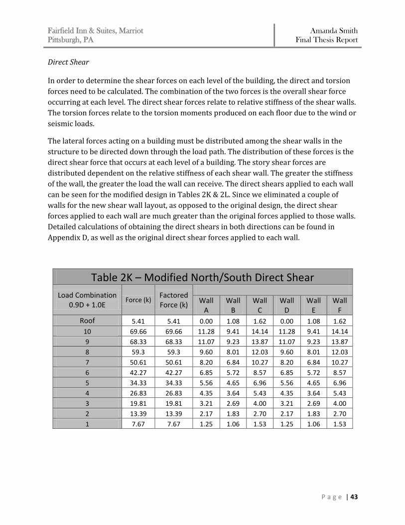
Direct Shear In order to determine the shear forces on each level of the building, the direct and torsion
forces need to be calculated. The combination of the two forces is the overall shear force
occurring at each level. The direct shear forces relate to relative stiffness of the shear walls.
The torsion forces relate to the torsion moments produced on each floor due to the wind or
seismic loads.
The lateral forces acting on a building must be distributed among the shear walls in the
structure to be directed down through the load path. The distribution of these forces is the
direct shear force that occurs at each level of a building. The story shear forces are
distributed dependent on the relative stiffness of each shear wall. The greater the stiffness
of the wall, the greater the load the wall can receive. The direct shears applied to each wall
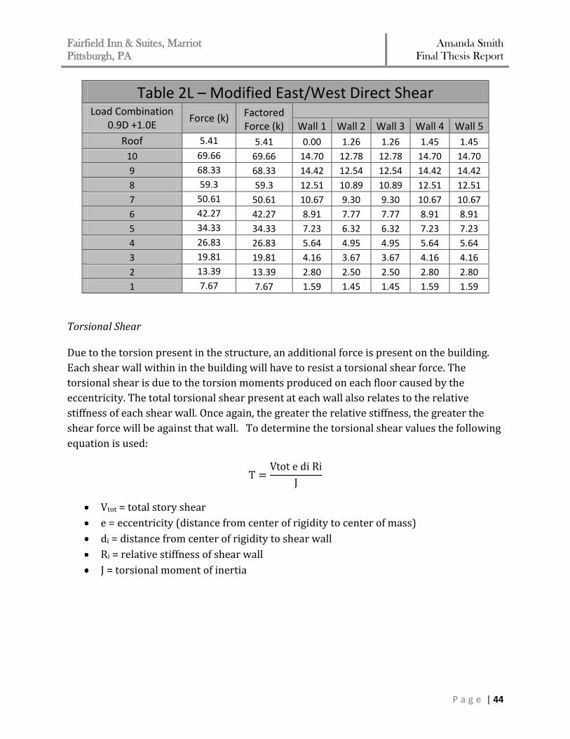
can be seen for the modified design in Tables 2K & 2L. Since we eliminated a couple of
walls for the new shear wall layout, as opposed to the original design, the direct shear
forces applied to each wall are much greater than the original forces applied to those walls.
Detailed calculations of obtaining the direct shears in both directions can be found in
Appendix D, as well as the original direct shear forces applied to each wall.
Table 2K – Modified North/South Direct Shear
Load Combination 0.9D + 1.0E
Force (k) Factored Force (k)
Wall A
Wall B
Wall C
Wall D
Wall E
Wall F
Roof 5.41 5.41 0.00 1.08 1.62 0.00 1.08 1.62
10 69.66 69.66 11.28 9.41 14.14 11.28 9.41 14.14
9 68.33 68.33 11.07 9.23 13.87 11.07 9.23 13.87
8 59.3 59.3 9.60 8.01 12.03 9.60 8.01 12.03
7 50.61 50.61 8.20 6.84 10.27 8.20 6.84 10.27
6 42.27 42.27 6.85 5.72 8.57 6.85 5.72 8.57
5 34.33 34.33 5.56 4.65 6.96 5.56 4.65 6.96
4 26.83 26.83 4.35 3.64 5.43 4.35 3.64 5.43
3 19.81 19.81 3.21 2.69 4.00 3.21 2.69 4.00
2 13.39 13.39 2.17 1.83 2.70 2.17 1.83 2.70
1 7.67 7.67 1.25 1.06 1.53 1.25 1.06 1.53
Fairfield Inn & Suites, Marriot
Pittsburgh, PA Amanda Smith
Final Thesis Report
P a g e | 44
Table 2L – Modified East/West Direct Shear Load Combination
0.9D +1.0E Force (k) Factored
Force (k)
Wall 1 Wall 2 Wall 3 Wall 4 Wall 5
Roof 5.41 5.41 0.00 1.26 1.26 1.45 1.45
10 69.66 69.66 14.70 12.78 12.78 14.70 14.70
9 68.33 68.33 14.42 12.54 12.54 14.42 14.42
8 59.3 59.3 12.51 10.89 10.89 12.51 12.51
7 50.61 50.61 10.67 9.30 9.30 10.67 10.67
6 42.27 42.27 8.91 7.77 7.77 8.91 8.91
5 34.33 34.33 7.23 6.32 6.32 7.23 7.23
4 26.83 26.83 5.64 4.95 4.95 5.64 5.64
3 19.81 19.81 4.16 3.67 3.67 4.16 4.16
2 13.39 13.39 2.80 2.50 2.50 2.80 2.80
1 7.67 7.67 1.59 1.45 1.45 1.59 1.59
Torsional Shear Due to the torsion present in the structure, an additional force is present on the building.
Each shear wall within in the building will have to resist a torsional shear force. The
torsional shear is due to the torsion moments produced on each floor caused by the
eccentricity. The total torsional shear present at each wall also relates to the relative
stiffness of each shear wall. Once again, the greater the relative stiffness, the greater the
shear force will be against that wall. To determine the torsional shear values the following
equation is used:
Vtot = total story shear
e = eccentricity (distance from center of rigidity to center of mass)
di = distance from center of rigidity to shear wall
Ri = relative stiffness of shear wall
J = torsional moment of inertia
Fairfield Inn & Suites, Marriot
Pittsburgh, PA Amanda Smith
Final Thesis Report
P a g e | 45
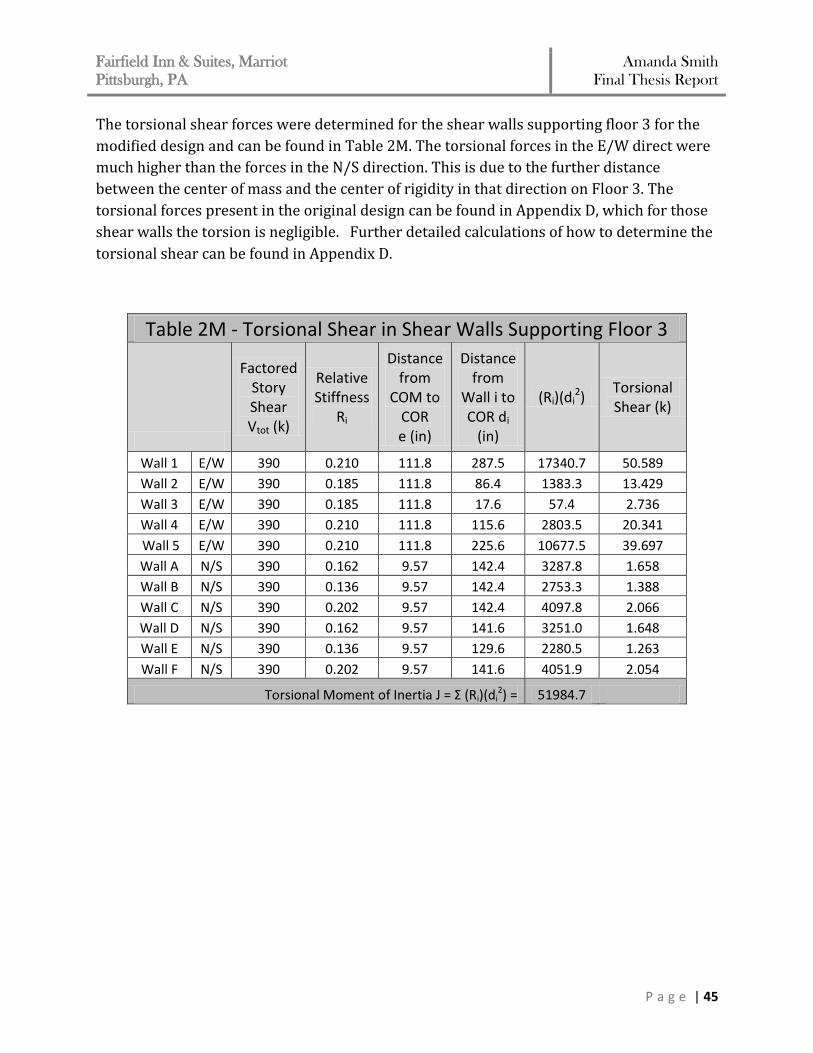
The torsional shear forces were determined for the shear walls supporting floor 3 for the
modified design and can be found in Table 2M. The torsional forces in the E/W direct were
much higher than the forces in the N/S direction. This is due to the further distance
between the center of mass and the center of rigidity in that direction on Floor 3. The
torsional forces present in the original design can be found in Appendix D, which for those
shear walls the torsion is negligible. Further detailed calculations of how to determine the
torsional shear can be found in Appendix D.
Table 2M - Torsional Shear in Shear Walls Supporting Floor 3
Factored Story Shear Vtot (k)
Relative Stiffness
Ri
Distance from
COM to COR e (in)
Distance from
Wall i to COR di
(in)
(Ri)(di2)
Torsional Shear (k)
Wall 1 E/W 390 0.210 111.8 287.5 17340.7 50.589
Wall 2 E/W 390 0.185 111.8 86.4 1383.3 13.429
Wall 3 E/W 390 0.185 111.8 17.6 57.4 2.736
Wall 4 E/W 390 0.210 111.8 115.6 2803.5 20.341
Wall 5 E/W 390 0.210 111.8 225.6 10677.5 39.697
Wall A N/S 390 0.162 9.57 142.4 3287.8 1.658
Wall B N/S 390 0.136 9.57 142.4 2753.3 1.388
Wall C N/S 390 0.202 9.57 142.4 4097.8 2.066
Wall D N/S 390 0.162 9.57 141.6 3251.0 1.648
Wall E N/S 390 0.136 9.57 129.6 2280.5 1.263
Wall F N/S 390 0.202 9.57 141.6 4051.9 2.054
Torsional Moment of Inertia J = Σ (Ri)(di2) = 51984.7
Fairfield Inn & Suites, Marriot
Pittsburgh, PA Amanda Smith
Final Thesis Report
P a g e | 46
Drift The overall drift of a building should be limited as much as possible. The drift is a
serviceability consideration that relates to the rigidity of each of the shear walls. The higher
a building, the more important the overall drift of a building becomes a factor. The wind
drift is limited to an allowable drift of Δ = ℓ/400. The seismic forces control the drift in the
both directions. The seismic drift is limited to an allowable drift of Δ = 0.015hsx. For the
Fairfield Inn and Suites the allowable building drift limit (at the top of the building) will be:
Δlimit = 0.015 x (1224”) = 18.36”
Each floor will be examined independently to determine an approximate story
displacement and story drift, adding up to overall building drift. A hand calculation was
done to determine the displacements on each floor, keeping in mind that the modulus of
elasticity and rigidity change as the f’c of shear walls supporting up to level 4 changes from
f’c = 8000 to f’c = 5000. The hand calculations done were determined using the following
equation:
Δcantilever = Δflexural + Δshear
The hand calculations done according to drift are an approximation. In order to computer
the story drift and displacements of all the shear walls working together by hand would be
very intricate. ETABS does analyze the drift and displacements with all the shear walls
working together as a lateral resisting system, therefore, the values computed by hand
can’t be directly compared with the ETAB results.
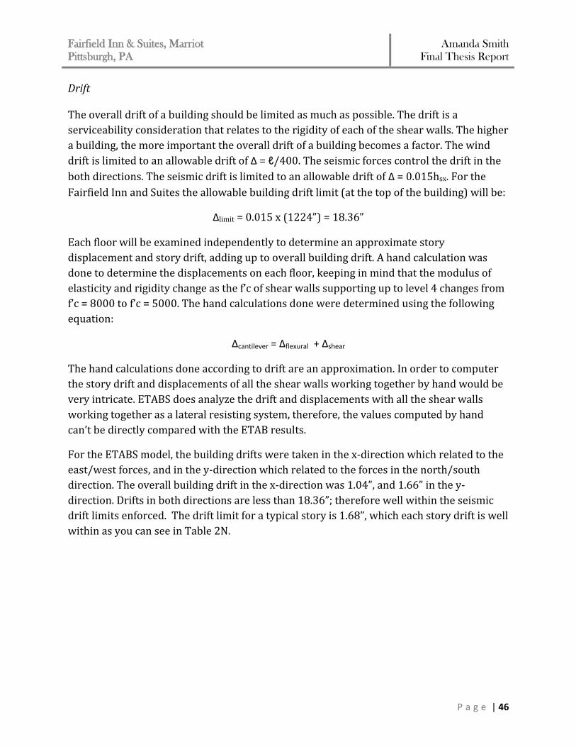
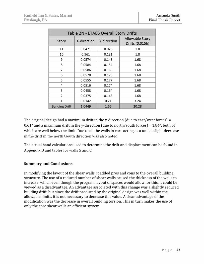
For the ETABS model, the building drifts were taken in the x-direction which related to the
east/west forces, and in the y-direction which related to the forces in the north/south
direction. The overall building drift in the x-direction was 1.04”, and 1.66” in the y-
direction. Drifts in both directions are less than 18.36”; therefore well within the seismic
drift limits enforced. The drift limit for a typical story is 1.68”, which each story drift is well
within as you can see in Table 2N.
Fairfield Inn & Suites, Marriot
Pittsburgh, PA Amanda Smith
Final Thesis Report
P a g e | 47
Table 2N - ETABS Overall Story Drifts
Story X-direction Y-direction Allowable Story Drifts (0.015h)
11 0.0471 0.026 1.8
10 0.561 0.131 1.8
9 0.0574 0.143 1.68
8 0.0584 0.154 1.68
7 0.0586 0.165 1.68
6 0.0578 0.173 1.68
5 0.0555 0.177 1.68
4 0.0516 0.174 1.68
3 0.0458 0.164 1.68
2 0.0375 0.143 1.68
1 0.0142 0.21 3.24
Building Drift 1.0449 1.66 20.28
The original design had a maximum drift in the x-direction (due to east/west forces) =
0.61” and a maximum drift in the y-direction (due to north/south forces) = 1.84”, both of
which are well below the limit. Due to all the walls in core acting as a unit, a slight decrease
in the drift in the north/south direction was also noted.
The actual hand calculations used to determine the drift and displacement can be found in
Appendix D and tables for walls 5 and C.
Summary and Conclusions In modifying the layout of the shear walls, it added pros and cons to the overall building structure. The use of a reduced number of shear walls caused the thickness of the walls to increase, which even though the program layout of spaces would allow for this, it could be viewed as a disadvantage. An advantage associated with this change was a slightly reduced building drift, but since the drift produced by the original design was well within the allowable limits, it is not necessary to decrease this value. A clear advantage of the modification was the decrease in overall building torsion. This in turn makes the use of only the core shear walls an efficient system.
Fairfield Inn & Suites, Marriot
Pittsburgh, PA Amanda Smith
Final Thesis Report
P a g e | 48
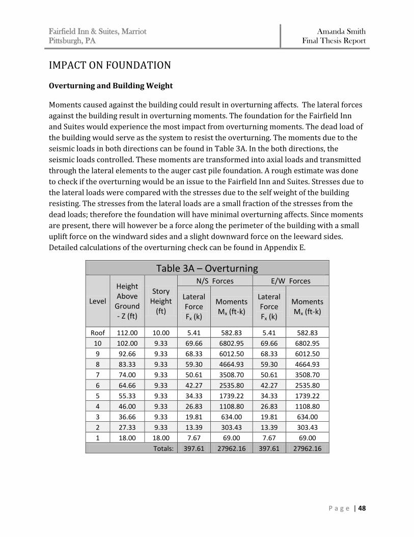
IMPACT ON FOUNDATION Overturning and Building Weight Moments caused against the building could result in overturning affects. The lateral forces
against the building result in overturning moments. The foundation for the Fairfield Inn
and Suites would experience the most impact from overturning moments. The dead load of
the building would serve as the system to resist the overturning. The moments due to the
seismic loads in both directions can be found in Table 3A. In the both directions, the
seismic loads controlled. These moments are transformed into axial loads and transmitted
through the lateral elements to the auger cast pile foundation. A rough estimate was done
to check if the overturning would be an issue to the Fairfield Inn and Suites. Stresses due to
the lateral loads were compared with the stresses due to the self weight of the building
resisting. The stresses from the lateral loads are a small fraction of the stresses from the
dead loads; therefore the foundation will have minimal overturning affects. Since moments
are present, there will however be a force along the perimeter of the building with a small
uplift force on the windward sides and a slight downward force on the leeward sides.
Detailed calculations of the overturning check can be found in Appendix E.
Table 3A – Overturning
Level
Height Above
Ground - Z (ft)
Story Height
(ft)
N/S Forces E/W Forces
Lateral Force Fx (k)
Moments Mx (ft-k)
Lateral Force Fx (k)
Moments Mx (ft-k)
Roof 112.00 10.00 5.41 582.83 5.41 582.83
10 102.00 9.33 69.66 6802.95 69.66 6802.95
9 92.66 9.33 68.33 6012.50 68.33 6012.50
8 83.33 9.33 59.30 4664.93 59.30 4664.93
7 74.00 9.33 50.61 3508.70 50.61 3508.70
6 64.66 9.33 42.27 2535.80 42.27 2535.80
5 55.33 9.33 34.33 1739.22 34.33 1739.22
4 46.00 9.33 26.83 1108.80 26.83 1108.80
3 36.66 9.33 19.81 634.00 19.81 634.00
2 27.33 9.33 13.39 303.43 13.39 303.43
1 18.00 18.00 7.67 69.00 7.67 69.00
Totals: 397.61 27962.16 397.61 27962.16
Fairfield Inn & Suites, Marriot
Pittsburgh, PA Amanda Smith
Final Thesis Report
P a g e | 49
Foundation Piles
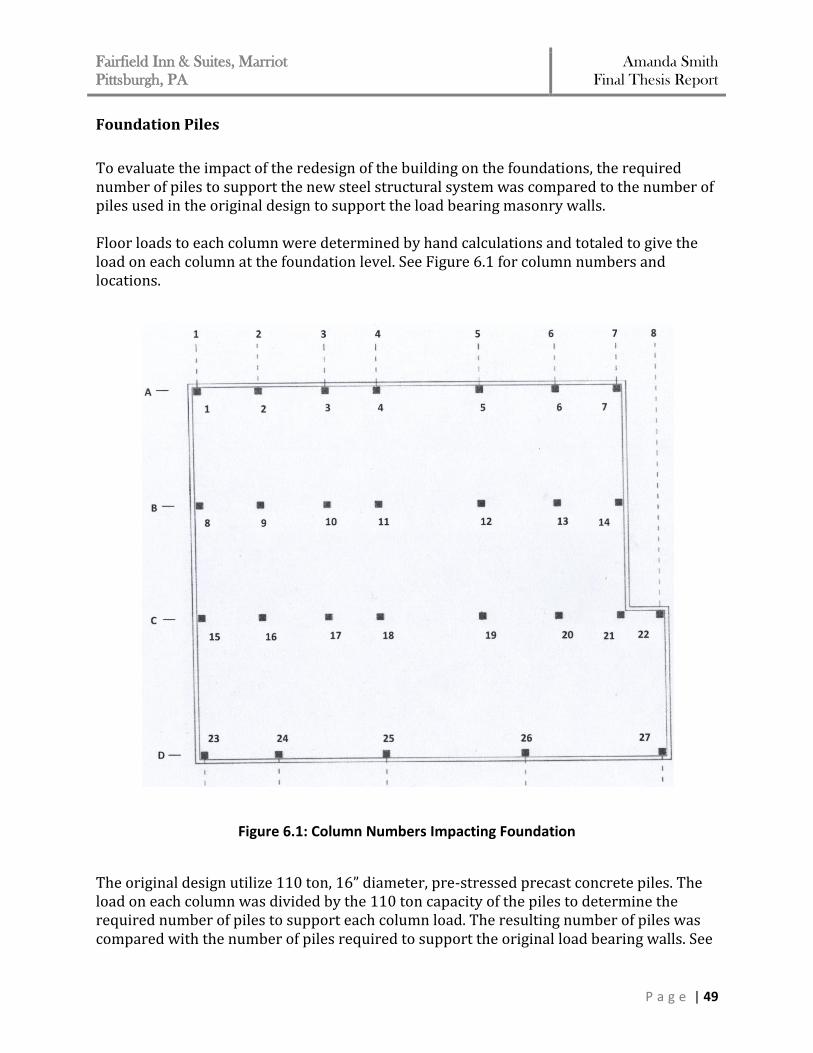
To evaluate the impact of the redesign of the building on the foundations, the required number of piles to support the new steel structural system was compared to the number of piles used in the original design to support the load bearing masonry walls. Floor loads to each column were determined by hand calculations and totaled to give the load on each column at the foundation level. See Figure 6.1 for column numbers and locations.
Figure 6.1: Column Numbers Impacting Foundation
The original design utilize 110 ton, 16” diameter, pre-stressed precast concrete piles. The load on each column was divided by the 110 ton capacity of the piles to determine the required number of piles to support each column load. The resulting number of piles was compared with the number of piles required to support the original load bearing walls. See
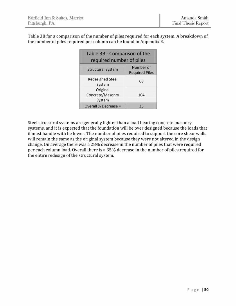
Fairfield Inn & Suites, Marriot
Pittsburgh, PA Amanda Smith
Final Thesis Report
P a g e | 50
Table 3B for a comparison of the number of piles required for each system. A breakdown of the number of piles required per column can be found in Appendix E.
Table 3B - Comparison of the required number of piles
Structural System Number of Required Piles
Redesigned Steel System
68
Original Concrete/Masonry
System 104
Overall % Decrease = 35
Steel structural systems are generally lighter than a load bearing concrete masonry systems, and it is expected that the foundation will be over designed because the loads that if must handle with be lower. The number of piles required to support the core shear walls will remain the same as the original system because they were not altered in the design change. On average there was a 28% decrease in the number of piles that were required per each column load. Overall there is a 35% decrease in the number of piles required for the entire redesign of the structural system.
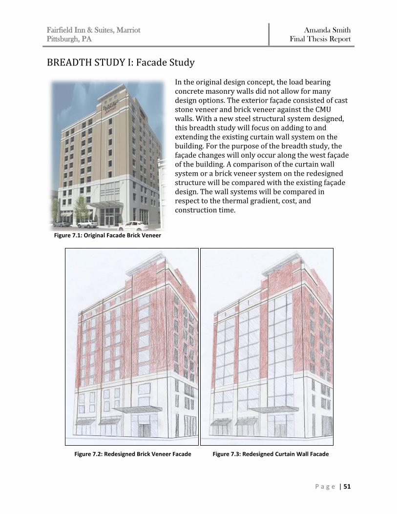
Fairfield Inn & Suites, Marriot
Pittsburgh, PA Amanda Smith
Final Thesis Report
P a g e | 51
BREADTH STUDY I: Facade Study In the original design concept, the load bearing concrete masonry walls did not allow for many design options. The exterior façade consisted of cast stone veneer and brick veneer against the CMU walls. With a new steel structural system designed, this breadth study will focus on adding to and extending the existing curtain wall system on the building. For the purpose of the breadth study, the façade changes will only occur along the west façade of the building. A comparison of the curtain wall system or a brick veneer system on the redesigned structure will be compared with the existing façade design. The wall systems will be compared in respect to the thermal gradient, cost, and construction time.
Figure 7.1: Original Facade Brick Veneer
Figure 7.2: Redesigned Brick Veneer Facade Figure 7.3: Redesigned Curtain Wall Facade

Fairfield Inn & Suites, Marriot
Pittsburgh, PA Amanda Smith
Final Thesis Report
P a g e | 52
Thermal Gradient Comparison The thermal gradient for each wall system was determined by establishing the thermal resistance (R-value) for each material within the wall. The R-values for the brick veneer system and the original design were determine in accordance with the 2001 ASHRAE Handbook – Fundamentals. The curtain wall system is an EFCO Series 5900 Wall System and the R-values were determined from the product specifications. Once the R-values were know, the temperature difference between the materials was determined by the following equation:
Tx = Toutdoor + (Tindoor – Toutdoor)(ΣRo-x/ΣRo-i) The following assumptions were made for these calculations:
1. The outdoor air temperature (Toutdoor) was taken as 0°F 2. The indoor air temerpature (Tindoor) was taken as 70°F 3. The relative humidity was taken as 50%
The thermal gradients for the original façade, curtain wall, and brick veneer wall systems
are shown in Figures 7.4, 7.5, & 7.6. Please refer to Appendix F for detailed calculations
showing how exactly these values were determined.
Existing CMU/Masonry System
Between Material
ΣRo-x (°F ft2 h/BTU)
Temperature (°F)
o - 1 0.17 0
1 - 2 0.28 0.931
2 - 3 1.54 5.12
3 - 4 2.86 9.51
4 - 5 16.61 55.24
5 - 6 19.81 65.88
6 - i 20.37 67.74
21.05 70
U = 0.0475 (BTU/°F ft2 h)
Figure 7.4: Existing Facade Thermal Gradient
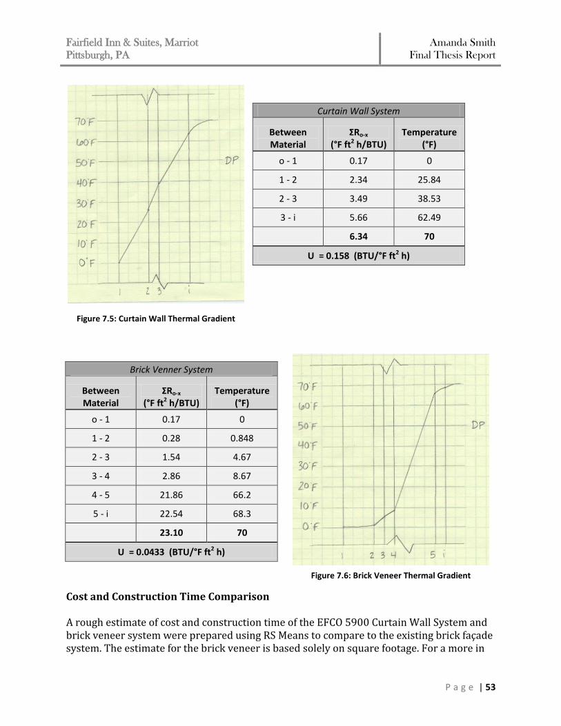
Fairfield Inn & Suites, Marriot
Pittsburgh, PA Amanda Smith
Final Thesis Report
P a g e | 53
Curtain Wall System
Between Material
ΣRo-x (°F ft2 h/BTU)
Temperature (°F)
o - 1 0.17 0
1 - 2 2.34 25.84
2 - 3 3.49 38.53
3 - i 5.66 62.49
6.34 70
U = 0.158 (BTU/°F ft2 h)
Brick Venner System
Between Material
ΣRo-x (°F ft2 h/BTU)
Temperature (°F)
o - 1 0.17 0
1 - 2 0.28 0.848
2 - 3 1.54 4.67
3 - 4 2.86 8.67
4 - 5 21.86 66.2
5 - i 22.54 68.3
23.10 70
U = 0.0433 (BTU/°F ft2 h)
Cost and Construction Time Comparison A rough estimate of cost and construction time of the EFCO 5900 Curtain Wall System and brick veneer system were prepared using RS Means to compare to the existing brick façade system. The estimate for the brick veneer is based solely on square footage. For a more in
Figure 7.5: Curtain Wall Thermal Gradient
Figure 7.6: Brick Veneer Thermal Gradient

Fairfield Inn & Suites, Marriot
Pittsburgh, PA Amanda Smith
Final Thesis Report
P a g e | 54
depth estimate, scaffolding would need to be considered when setting brick veneer. However, for this breadth, a simple square footage analysis is sufficient to get the overall idea of the differences between each system. The estimate for each wall system is summarized in Table 4 below.
Table 4 – Façade Comparisons
Façade of Existing Structural Design
Wall System S.F. Crew Size
Material Cost
Labor Cost
Total Cost Daily
Output Construction
Time
CMU/Brick Veneer System
5734 3 Layers $10.92 $14.13 $143,637 540 11 days
Façade Systems with Redesigned Structural System
Wall System S.F. Crew Size
Material Cost/SF
Labor Cost/SF
Total Cost Daily
Output Construction
Time
Curtain Wall System
5734 2 Glaziers $30.49 $6.94 $214,624 410 14 days
Brick Veneer System
5734 3 Brick Layers
$6.95 $8.94 $91,113 660 7 days
Conclusions The thermal gradient of the brick veneer wall system is very gradual due to the batting insulation used within the system. This is the same with the original CMU/Brick veneer system. In determining which system would be most efficient with the redesign of the structural system, the comparison of the heat transfer values (U-values) determines that the curtain wall system transfers approximately 27.4% more BTU/hr than the brick veneer system. Therefore, it can be concluded that utilizing the brick veneer system along the west façade would minimize the heat loss within the guest rooms. This would take away from the esthetics the curtain wall would bring to the room by allowing more light to enter, but ultimately occupant comfort would be improved by utilizing the brick veneer system. In addition, the brick veneer wall is more cost efficient with respect to construction time. As previously stated, scaffolding for the brick veneer would add to overall cost, however it can still be concluded that the installation of the brick veneer system is more efficient than that of the curtain wall system. It is recommended that the façade on the redesigned structural system implements the brick veneer.

Fairfield Inn & Suites, Marriot
Pittsburgh, PA Amanda Smith
Final Thesis Report
P a g e | 55
BREADTH STUDY II: Construction Management To further determine which structural system would be most viable for the Fairfield Inn and Suites, a cost and schedule comparison was conducted between the load bearing concrete masonry walls and the steel framing. In utilizing a steel structural system, the erection time of steel is much faster than CMU load bearing walls. The reduction of shear walls that would need to be constructed will impact the schedule as well. Ideally, this would save significant time on the construction schedule which will ultimately allow the Fairfield Inn and Suites to open sooner. The redesign of the structural system did not greatly impact the foundation or the interior layout of the building. Therefore, the assumption will be made that only the structural system would impact the construction schedule and alter the cost of the building. For these reasons, a schedule and cost analysis was prepared for both the existing structural system and the redesigned structural system. Construction Schedule Comparison Construction Schedule of Existing Structural System The existing structural system of the Fairfield Inn and Suites was scheduled to start on February 26, 2009. The construction of the masonry bearing structure was estimated to take approximately six months by being completed by August 13, 2009. A schedule for the structural system construction coordinates the placement of the block walls and the setting of the precast plank floors, in addition to the minimal transfer beam erection. A summary of the construction time is provided in Table 5A. Please refer to Appendix G to view a more detailed construction schedule for the existing structure. Construction Schedule of Redesigned Structural System The redesigned structural system will schedule to have the same start date of February 26, 2009. The steel erection and construction of the shear walls was estimated to take approximately 2 months by being completed on April 24, 2009. A lot of construction time was saved by utilizing the steel structural system. Steel erection impacted the construction schedule of the structural system by cutting it in half. A mock construction schedule for the structural system was created that coordinates the erection of the steel, placement of the block walls, and setting the precast plank floor. For a detailed construction schedule of the redesigned structural system, please refer to Appendix G. It must be noted, the steel erection does greatly reduce the construction schedule, but it may also increase the lead time of the project by coordinating all the steel members that are now required.
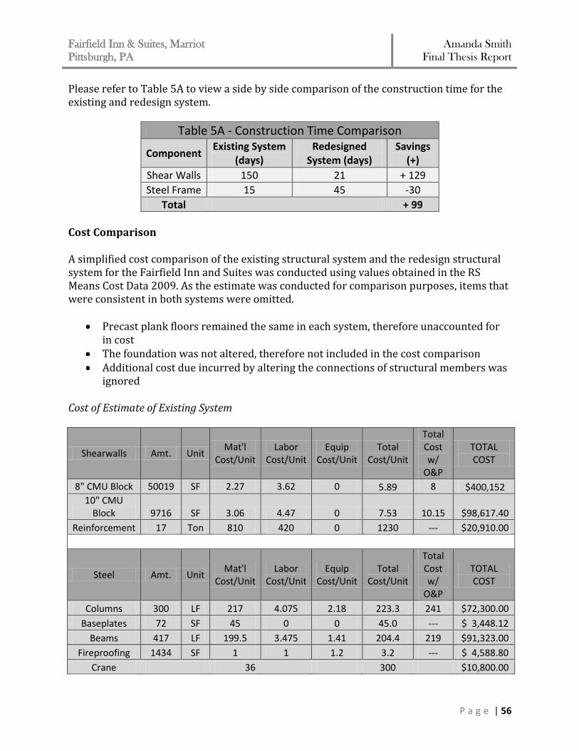
Fairfield Inn & Suites, Marriot
Pittsburgh, PA Amanda Smith
Final Thesis Report
P a g e | 56
Please refer to Table 5A to view a side by side comparison of the construction time for the existing and redesign system.
Table 5A - Construction Time Comparison
Component Existing System
(days) Redesigned
System (days) Savings
(+)
Shear Walls 150 21 + 129
Steel Frame 15 45 -30
Total + 99
Cost Comparison A simplified cost comparison of the existing structural system and the redesign structural system for the Fairfield Inn and Suites was conducted using values obtained in the RS Means Cost Data 2009. As the estimate was conducted for comparison purposes, items that were consistent in both systems were omitted.
Precast plank floors remained the same in each system, therefore unaccounted for in cost
The foundation was not altered, therefore not included in the cost comparison Additional cost due incurred by altering the connections of structural members was
ignored Cost of Estimate of Existing System
Shearwalls Amt. Unit Mat'l
Cost/Unit Labor
Cost/Unit Equip
Cost/Unit Total
Cost/Unit
Total Cost w/
O&P
TOTAL COST
8" CMU Block 50019 SF 2.27 3.62 0 5.89 8 $400,152
10" CMU Block 9716 SF 3.06 4.47 0 7.53 10.15 $98,617.40
Reinforcement 17 Ton 810 420 0 1230 --- $20,910.00
Steel Amt. Unit Mat'l
Cost/Unit Labor
Cost/Unit Equip
Cost/Unit Total
Cost/Unit
Total Cost w/
O&P
TOTAL COST
Columns 300 LF 217 4.075 2.18 223.3 241 $72,300.00
Baseplates 72 SF 45 0 0 45.0 --- $ 3,448.12
Beams 417 LF 199.5 3.475 1.41 204.4 219 $91,323.00
Fireproofing 1434 SF 1 1 1.2 3.2 --- $ 4,588.80
Crane 36
300 $10,800.00
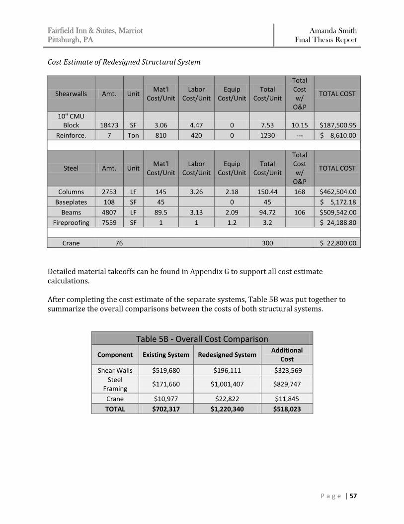
Fairfield Inn & Suites, Marriot
Pittsburgh, PA Amanda Smith
Final Thesis Report
P a g e | 57
Cost Estimate of Redesigned Structural System
Shearwalls Amt. Unit Mat'l
Cost/Unit Labor
Cost/Unit Equip
Cost/Unit Total
Cost/Unit
Total Cost w/
O&P
TOTAL COST
10" CMU Block 18473 SF 3.06 4.47 0 7.53 10.15 $187,500.95
Reinforce. 7 Ton 810 420 0 1230 --- $ 8,610.00
Steel Amt. Unit Mat'l
Cost/Unit Labor
Cost/Unit Equip
Cost/Unit Total
Cost/Unit
Total Cost w/
O&P
TOTAL COST
Columns 2753 LF 145 3.26 2.18 150.44 168 $462,504.00
Baseplates 108 SF 45 0 45 $ 5,172.18
Beams 4807 LF 89.5 3.13 2.09 94.72 106 $509,542.00
Fireproofing 7559 SF 1 1 1.2 3.2 $ 24,188.80
Crane 76 300 $ 22,800.00
Detailed material takeoffs can be found in Appendix G to support all cost estimate calculations. After completing the cost estimate of the separate systems, Table 5B was put together to summarize the overall comparisons between the costs of both structural systems.
Table 5B - Overall Cost Comparison
Component Existing System Redesigned System Additional
Cost
Shear Walls $519,680 $196,111 -$323,569
Steel Framing
$171,660 $1,001,407 $829,747
Crane $10,977 $22,822 $11,845
TOTAL $702,317 $1,220,340 $518,023
Fairfield Inn & Suites, Marriot
Pittsburgh, PA Amanda Smith
Final Thesis Report
P a g e | 58
Conclusion
The use of the steel structural system significantly impacts the cost and construction time
of the Fairfield Inn and Suites. Since steel erection can be installed at a higher quantity per
day than CMU, the construction time was reduced by approximately 66% in regards to the
structural system construction only. In addition, with the high reduction in the
construction schedule, the steel structural system is not the most cost efficient for the
building. The redesigned system costs approximately 42% most than the existing structural
system.
In the event that the hotel would want to be completed faster to make a necessary deadline,
the use of the steel structural system could be an efficient option, but the shortened
construction time will result in an increase in cost the owner.
Fairfield Inn & Suites, Marriot
Pittsburgh, PA Amanda Smith
Final Thesis Report
P a g e | 59
CONCLUSION AND RECOMMENDATIONS
The main focus of this final thesis report is to optimize the gravity and lateral systems of
the Fairfield Inn and Suites. Classified as Seismic Site Class D soil, it was necessary at the
time of the design to utilize a steel structural system in order to reduce the load on the
supporting foundation at such a poor soil site. While this design exhibits no problems
structurally, both systems are possible areas of optimization for the building.
The gravity system proves that the use of steel moment frame system considerably reduces
the overall building weight. The framing plan conducted in the redesign conformed easily
to the existing architectural layout, while not affecting the structural depth of the floor
system. The system does cut done on construction time, but would not be cost effective.
Without having any negative effects on the layout of the building, the reduced building
weight does improve the efficiency of the gravity system on the foundation and soil class.
While seismic loads still controlled despite the reduced loads, the base shear value was
decreased by approximately 32%. This allowed for a reduction of shear walls that made up
the lateral force resisting system. The use of shear walls in the redesign of the lateral
system was chosen to keep consistency around the core areas of the building, similar to the
original design. As a result, the core shear walls were designed slightly thicker to
compensate for the loss of exterior shear wall, without adding weight to the building. The
lateral system optimization study favors the modified shear wall layout in comparison to
the original design because less building torsion is present on the building while drift is still
well within the limits set forth by the code. This in fact would reduce the number of piles
required by the foundation system to support the overall redesigned structural system.
The façade breadth study focuses on improvements in guest comfort with respect to
natural daylight penetration verse heat transfer through the wall system. By implementing
the brick veneer system, the heat transfer through the wall would not be affected, as
opposed to using the larger curtain wall system façade option which would increase the
heat transfer by approximately 70%. Therefore, choosing the system with a lower heat
transfer rate verse the amount of natural daylight it allows in the room is more efficient for
the building.
The goals of this thesis were to create an efficient optional gravity and lateral system for
the Fairfield Inn and Suites. Based on the results discussed, these goals are clearly met. If
cost was not an issue, it is the recommendation of the author to implement the changes
proposed, as each study does impact the building in a positive way from a feasibility
standpoint.
Fairfield Inn & Suites, Marriot
Pittsburgh, PA Amanda Smith
Final Thesis Report
P a g e | 60
CODES & REFERENCES
American Concrete Institute (2008) Building Code Requirements for Structural Concrete (ACI 318-08), ACI, Farmington Hills, MI American Concrete Institute (2005) Building Code Requirements for Masonry Structures (ACI 530-99), ACI, Farmington Hills, MI American Institute of Steel Construction (2005) Steel Construction Manual, Thirteenth Edition, AISC, Chicago, IL American Society of Civil Engineers (2005) ASCE 7-05: Minimum Design Loads for Building and Other Structures, ASCE, Reston, VA Concrete Masonry Association (2006) Design of Reinforced Masonry Structures, 5th Edition, CMACN, Citrus Heights, CA EFCO Walls, www.efco-usa.com
ETABS Nonlinear v9.2.0, copyright 2008 (Computers and Structures, Inc.) Geschwindner, L. (2008) Unified Design of Steel Structures, John Wiley and Sons, Inc., Hoboken, NJ International Code Council (2006) International Building Code, ICC Inc, County Club Hills, IL PCI Concrete (2004) PCI Design Handbook: Precast/Prestressed Concrete Institute, 6th Edition, PCI, Chicago, IL RSMeans Construction Publishers and Consultants. Building Construction Cost Data 2008 66th Annual Edition. Reed Construction Data, Inc.: Kingston, MA, 2007. Staad.Pro Software v6.1, copyright 2007 (Research Engineers, Intl.)