fakulti kejuruteraan elektrik universiti teknikal …eprints.utem.edu.my/18229/1/development of an...
TRANSCRIPT

FAKULTI KEJURUTERAAN ELEKTRIK
UNIVERSITI TEKNIKAL MALAYSIA MELAKA
LAPORAN PROJEK
SARJANA MUDA
DEVELOPMENT OF AN ACTIVE BRAKING SYSTEM FOR A GO KART
LEE YEE CHERN
Bachelor of Mechatronics Engineering
May 2015

i
“I hereby declare that I have read through this report entitle “Development of an
Active Braking System for a Go-kart” and found that it has comply the partial
fulfilment for awarding the degree of Bachelor of Mechatronics Engineering.
Signature : ………………………..
Supervisor’s Name : ………………………..
Date : ………………………..
ii
DEVELOPMENT OF AN ACTIVE BRAKING SYSTEM FOR A GO KART
LEE YEE CHERN
A report submitted in partial fulfilment of the requirements for the degree
of Mechatronics Engineering
Faculty of Electrical Engineering
UNIVERSITI TEKNIKAL MALAYSIA MELAKA
2014 / 2015

iii
I declare that this report entitle “Development of an Active Braking System for a Go-
kart” is the result of my own research except as cited in the references. The report has
not been accepted for any degree and is not concurrently submitted in candidature of
any other degree.
Signature :
Name :
Date :

i
Acknowledgement
First and foremost, I would like to express my gratitude to my supervisor,
Encik Zamzuri Bin Ab Rashid for his guidance and patience in my Final Year Project
progress throughout this semester. Encik Zamzuri is a pleasant and friendly supervisor.
When I met any problems in my progress, he would explain and guide me towards the
correct direction in engineering perspective. Besides, he is also patient and gives full
attention to me whenever I raised questions regarding my project. Not only that, his
constructive criticism also pushed me to work harder to complete this project. It is my
pleasure to work together with Encik Zamzuri.
Next, I would like to thank my panels, Puan Norafizah Binti Abas and
Dr.Ahmad Zaki Bin Shukor for providing important feedback on my report and
research progress. Puan Norafizah Binti Abas has patiently marked my progress
report and gave correctional comments for me to improve this report before the final
evaluation.
Last but not least, I would like to thank my dearest family and friends for
giving me support and encouragement to complete my final year project. Special
thanks to my dearest Lim Khai Yun, for being supportive and being there for me all
the time.

ii
Abstract
This report presents the development of an active braking system for a go-kart.
The active braking system is a noble invention where its benefit is significant to
improve driving safety and to save human life during an emergency situation. The
development of this electromechanical brake system is significant to the progress of
the automobile technology towards the eco-friendly or green technology, as the
electromechanical braking system mitigates the usage of hydraulic fluid; whereby
common problems such as improper disposal of used hydraulic fluid or leaked
hydraulic fluid pollutes our environment. Besides, driving safety of a vehicle greatly
improves when active braking system such as anti-locking brakes, traction control
system and vehicle stability control is implemented in a vehicle. The active braking
system is implemented by designing an electromechanical braking system. The basic
requirement of an active braking system is that actuators component in the system has
to be electrically powered and controlled using electronic controllers. The
electromechanical brake system consists of a linear actuated stepper motor as the
brake actuator, an Arduino Uno R3 as the brake system microcontroller, IR coupling
sensor as the wheel speed sensor and a potentiometer as the brake pedal, whereby
certain conventional brake components such as brake disc and brake pads are being
used as well. The linear actuated stepper motor must be able to provide strong thrust
force and quick response time for a good braking performance. The brake caliper
assembly has to be light weight and easy to assemble or disassemble for regular
maintenance work. An IR sensor coupling is used to provide signal pulses for wheel
speed measurement for the Anti-locking Brake System (ABS) and wheel slip control
(TRC) that was implemented in the active braking system. To achieve the objective of
this project, an active braking system for a go-kart will be developed and a test bench
will be fabricated to test the completed electromechanical braking system.
iii
ABSTRAK
Laporan ini membentangkan pembinaan sistem brek aktif untuk go-kart. Pembinaan
sistem brek elektromekanikal ini mempunyai impak yang kuat terhadap kemajuan
teknologi otomobil ke arah teknologi hijau, dimana cecair brek tidak digunakan dalam
sistem brek elektromekanikal ini, mengurangkan masalah biasa seperti kebocoran
cecair brek yang menyebabkan pencemaran alam sekitar. Bukan itu sahaja,
keselamatan permanduan juga diperbaikkan apabila teknologi aktif seperti Anti-
Locking Brake dan Traction Control digunaankan dalam sesuatu kenderaan. Sistem
brek aktif ini adalah ciptaan yang penting dimana ia menaikkan taraf keselamatan
pemandu kenderaan dan mampu menyelamatkan nyawa manusia semasa keadaan
kecemasan. Sistem brek aktif ini dilaksanakan melalui rekaan cipta suatu sistem brek
elektromekanikal. Keperluan asas untuk sesuatu system brek aktif ialah komponen
penggeraknya mesti dikuasai elektrik dan dikawal oleh pengawal elektronik. Sistem
brek elektromekanikal ini terdiri daripada satu linear actuated stepper motor,
mikropengawal Arduino, satu set pengesan inframerah, dan pedal brek elektronik,
dimana komponen brek biasa seperti cakera brek, pad brek juga digunakan. Linear
actuated stepper motor perlu mempunyai kuasa cengkaman yang kuat untuk memberi
prestasi baik untuk brek dan cepat balasan breknya . Pemasangan angkup brek perlu
ringan dan mudah dipasang untuk mempermudahkan kerja pengelengaraan. Set
pengesan inframerah memberi isyarat nadi bagi menentukan kelajuan putaran roda
untuk sistem Anti-Locking Brake dan Traction Control dalam system brek aktif ini.
Untuk mencapai objektif projek ini, suatu sistem brek aktif untuk go-kart akan dibina
dan diuji atas bangku ujian sistem brek elektromekanikal.

iv
Table of Contents
Chapter Title Page
Abstract i
Abstrak ii
Acknowledgement iii
Lists of Figures iv
Lists of Tables v
1 Introduction
1.1 Motivation 1
1.2 Problem Statement 2
1.3 Objectives 2
1.4 Scopes 3
2 Literature Review
2.0 Overview 4
2.1 Literature review on design 4
2.2 Literature review on system modeling 8
2.3 Literature review on controller algorithm 15
2.4 Literature review on system performance 17
2.5 Summary table for literature review 20
2.5.1 Summary for design 20
2.6 Chapter Conclusion 21
3 Methodology
3.0 Overview 22
3.1 Methodology flowchart 23
3.2 Methodology flowchart explanation 24
3.3 System Operation Flowchart 25
3.4 System design sketch
3.4.1 Sketch No.1
26

v
3.4.2 Sketch No.2
3.4.3 Sketch No.3
3.4.4 Sketch No.4
3.4.5 Sketch No.5
3.4.5 Sketch No.6
3.5 Table of advantages and disadvantages of each design sketch 29
3.6 Table of component used in each design sketch 31
3.7 Material Selection 32
3.7.1 Hardware material 32
3.7.2 Electric actuator selection 33
3.7.3 Mechanical actuator selection 35
3.7.4 Controller hardware selection 37
3.7.5 Controller algorithm selection 38
3.8.1 System Operation Method
3.8.1 Rotation of Disc Brake on Test Bench 40
3.8.2 Measurement of Disc Brake’s Rotation 41
3.8.3 Controller Unit of the Electromechanical 42
Brake System
3.8.4 Actuation of Electromechanical Brake 43
3.9 Lists of experiments
3.9.1: Experiment 1: SolidWorks Evaluation of Mass 44
Properties through Simulation
3.9.2: Experiment 2: MATLAB Simulink ABS Simulation 44
3.9.3 Experiment 3: Determine Maximum Velocity of Disc 45
Brake
3.9.4 Experiment 4: Braking Performance with Maximum 46
Braking Torque Applied
3.9.5 Experiment 5: Braking Performance with Intermittent 47
Maximum Braking Torque
3.9.6 Experiment 6: Triggering Anti-Locking Brake (ABS) 48
System
3.10 Chapter Conclusion 48

vi
4 Result & Analysis
4.0 Overview 49
4.1 SolidWorks design (Electromechanical Brake Assembly)
4.1.1 SolidWorks design in isometric view 49
4.1.1.1 Components in EMB Assembly 50
4.1.2 SolidWorks design in exploded view 51
4.1.3 SolidWorks design in front view 52
4.1.4 SolidWorks design in side view 53
4.1.5 SolidWorks design in top view 53
4.2 SolidWorks design (Test Bench)
4.2.1 SolidWorks in isometric view 54
4.2.2 SolidWorks in front view 54
4.2.3 SolidWorks in side view 55
4.2.4 SolidWorks in top view 55
4.3 Complete assembly of EMB on test bench 56
4.4 Experiment Results
4.4.1 Experiment 1: SolidWorks Mass Properties Data 57
Results
4.4.2: Experiment 2: MATLAB Simulink ABS Simulation 61
4.4.3 Experiment 3: Determine Maximum Velocity of Disc 64
Brake
4.4.4 Experiment 4: Braking Performance with Maximum 67
Braking Torque Applied
4.4.5 Experiment 5: Braking Performance with Intermittent 69
Maximum Braking Torque
4.4.6 Experiment 6: Triggering Anti-Locking Brake (ABS) 73
System
4.5 Comparison and Analysis of all Braking Tests 74
4.6 Fitting of Disc Brake Actuator on Go-Kart 75
5 Conclusion and Recommendation 77
References 78
Appendix 81

vii
List of Figures
Figure Title Page
2.1.1 Electromechanical brake caliper using Servomotor [1] 4
2.1.2 Electromechanical brake caliper using Brushless DC motor [2] 5
2.1.3 Wedge type electromechanical brake caliper using DC motor [14] 6
2.1.4 Electromechanical brake caliper with built-in linear actuated motor
[16]
7
2.1.5 Electromechanical brake caliper using a Switch-Reluctance Motor
(SRM) [17]
7
2.2.1 Motor torque friction model [1] 9
2.2.2 Diagram showing the screw radius, head and pitch of lead screw [1] 10
2.2.3 Static friction model [1] 10
2.2.4 A model showing the forces acting on a braking vehicle [2] 12
2.2.5 A tire model showing forces acting on a braking tire [2] 12
2.3.1 Clamping force control loop of a PID controller [1] 15
2.3.2(a) An overall architecture of a PI controller [4] 15
2.3.2(b) Graph of motor angular displacement against clamping force [4] 16
2.3.3 Cascaded triple loop using PI controller 16
2.4.1(a) Step-wise input graph of clamping force against time [1] 17
2.4.1(b) Step-wise input graph of motor torque against time [1] 17
2.4.2(a) Ramp-wise input graph of clamping force against time [1] 18
2.4.2(b) Ramp-wise input graph of motor torque against time [1] 18
2.4.3 Comparison graph between target, measured and estimated clamping
force relative to time [1]
18
2.4.4 Graph of ball screw feed against time [2] 19
2.4.5 Graph of actual clamping force compared to estimated clamping
force [4]
19
3.1.1 Flowchart of project progress 23
3.3.1 Flowchart of system operation 25
3.4.1 EMB Sketch No.1 26

viii
3.4.2 EMB Sketch No.2 26
3.4.3 EMB Sketch No.3 27
3.4.4 EMB Sketch No.4 27
3.4.5 EMB Sketch No.5 28
3.4.6 EMB Sketch No.6 28
3.7.1.1 Brake Caliper 32
3.7.1.2 Brake Caliper with Brake Pad 32
3.7.1.3 Cross Drilled Rotor 33
3.7.2.1 Linear Actuated Stepper Motor 33
3.7.2.2 Linear Actuated Stepper Motor with Piston attached 34
3.7.2.3 Infrared Coupling 35
3.7.3.1 Brake Pedal 35
3.7.3.2 Potentiometer 36
3.7.4.1 Arduino UNO chipset 37
3.7.5.1 Block Diagram of the Electromechanical Brake System 38
3.7.5.2 Controller Unit 38
3.7.5.3 Detailed schematic diagram of controller circuit 39
3.8.1.1 AC Motor used to drive disc brake using pulley and belt system 40
3.8.2.1 Tachometer setup using Infrared sensor circuit 42
3.8.3.1 Front view of the controller unit 42
3.8.3.2 Back view of the controller unit 42
3.8.4.1 Actuating the brake caliper’s piston to apply brakes 43
3.8.2.1 Dynamic behavior simulation of a vehicle with ABS under braking
condition
44
3.9.3.1 Experimental setup 45
3.9.4.1 Experimental setup 46
3.9.4.2 Experiment setup before running AC motor 46
3.9.4.3 Experiment setup when running AC Motor 46
4.1.1.1 Electromechanical Brake Assembly 49
4.1.1.2 Linear Stepper Motor 50
4.1.1.3 Brake Disc 50
4.1.1.4 Wheels Mounting Hub 50
4.1.1.5 Brake Pads 50

ix
4.1.2.1 Exploded view of the Electromechanical Brake Assembly 51
4.1.3.1 Front View of Electromechanical Brake 52
4.1.3.2 Back view of Electromechanical Brake 52
4.1.4.1 Side view of Electromechanical Brake 53
4.1.5.1 Top view of Electromechanical Brake 53
4.2.1.1 Isometric view of Test Bench 54
4.2.2.1 Front view of Test Bench 54
4.2.3.1 Side view of Test Bench 55
4.2.4.1 Top view of Test Bench 55
4.3.1 SolidWorks isometric view of the complete test bench with the
electromechanical brake assembly assembled
56
4.3.2 Actual isometric view of the complete test bench with the
electromechanical brake assembly assembled
56
4.4.1.1 Axis coordinate of disc brake at centre of mass 57
4.4.1.2 Axis coordinate of wheel hub at centre of mass 58
4.4.1.3 Axis coordinate of drive shaft at centre of mass 59
4.4.2.1 Graph of comparison between vehicle speed and wheel speed with
ABS
61
4.4.2.2 Graph of comparison between vehicle speed and wheel speed without
ABS
61
4.4.2.3 Relative Slip of tyre on road surface with ABS 62
4.4.2.4 Relative Slip of tyre on road surface without ABS 62
4.4.3.1 Chart of current of AC motor vs linear velocity of disc brake 66
4.4.4.1 Graph of time against velocity for braking without ABS 68
4.4.5.1 Graph of time against velocity for braking with ABS with 1 pulse 70
4.4.5.2 Graph of time against velocity for braking with ABS with 2 pulse 72
4.5.1 Graph of time required to reach full stop from initial velocity for all
braking tests
74
4.6.1 Fitting the electromechanical brake system on a go-kart 75
4.6.2 Electromechanical brake system with tyres attached 75
4.6.3 Photo showing the electromechanical brake system on a go-kart 76
4.6.4 Electromechanical brake system side view 76
x
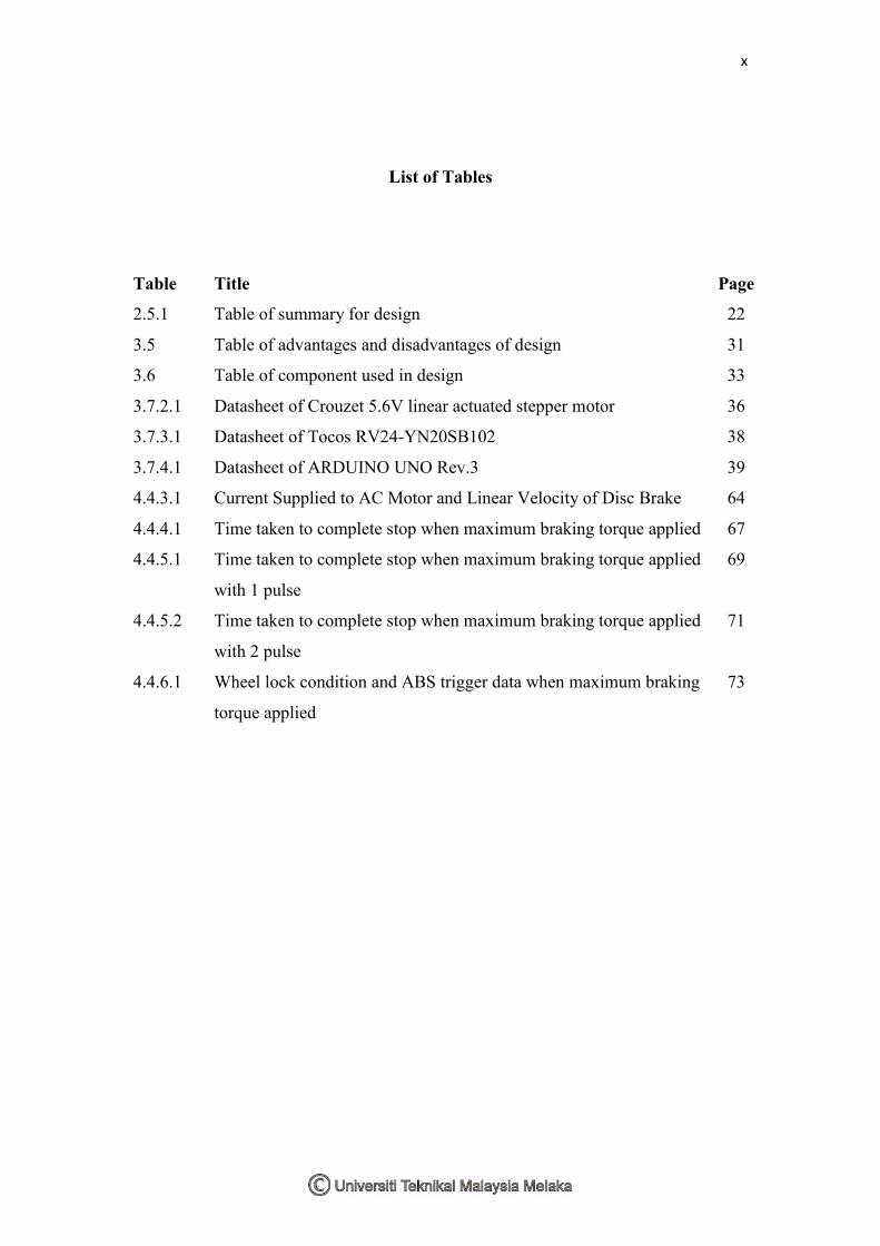
List of Tables
Table Title Page
2.5.1 Table of summary for design 22
3.5 Table of advantages and disadvantages of design 31
3.6 Table of component used in design 33
3.7.2.1 Datasheet of Crouzet 5.6V linear actuated stepper motor 36
3.7.3.1 Datasheet of Tocos RV24-YN20SB102 38
3.7.4.1 Datasheet of ARDUINO UNO Rev.3 39
4.4.3.1 Current Supplied to AC Motor and Linear Velocity of Disc Brake 64
4.4.4.1 Time taken to complete stop when maximum braking torque applied 67
4.4.5.1 Time taken to complete stop when maximum braking torque applied
with 1 pulse
69
4.4.5.2 Time taken to complete stop when maximum braking torque applied
with 2 pulse
71
4.4.6.1 Wheel lock condition and ABS trigger data when maximum braking
torque applied
73

1
CHAPTER 1
INTRODUCTION
1.1 Motivation
In recent years, electromechanical braking system (EMB) has gained
worldwide popularity and had a strong development support by the automobile
manufacturers. Motivation to research on the electromechanical braking system is to
overcome certain problems caused by the hydraulic braking system.
Firstly, the United States Environmental Protection Agency (EPA) reported
that there are 7.5 million liters of used hydraulic fluid that were improperly disposed
yearly [20]. It is a significant improvement for the environment as the
electromechanical brakes doesn’t use any hydraulic fluid. Besides, leakage of the
hydraulic fluid is also a common problem found in vehicles with hydraulic braking
system.
Next, hydraulic braking system has long brake lines and excessive brake pipe
valve components that often lead to the delay of hydraulic transmission time, weak
dynamic response speed, and these disadvantages are responsible for the increased
braking distance and reduced driving security [2].
Moreover, the electromechanical brakes have faster braking response due to
the motor dynamics. Based on a journal in 2010 [4], the motor-driven brake system
can apply the braking force more quickly and more accurately than conventional
brake system.
Finally, the gaining popularity of go-karts in motorsports has brought an
interest to develop a more advanced and satisfied driving experience. Therefore, it is
essential to provide a safe go-kart platform for the amateurs and professionals at an
affordable cost of utilizing the electromechanical braking system.

2
1.2 Problem Statement
When the project is in progress, I have found several problems related to the
electromechanical brake system. Firstly, the selected linear actuated motor have a
linear thrust force 58N only and it is inversely proportional to the rotational speed of
the stepper motor. To achieve a good braking performance, the electromechanical
brake must have two essential properties, which is strong clamping force and quick
braking response time. Therefore, I have to make several experiments to achieve an
optimum setting of linear trust force and motor rotational speed. At the same time,
the brake assembly must be reliable, light-weight, easy to assemble and dissemble
during maintenance work. Next, the Arduino Uno R3 controller has a processing
speed of only 16Mghz, where by the speed of execution is limited by the hardware
itself. I found that the Arduino Uno R3 can only handle one interrupt process at a time,
although it has two interrupt pins at Digital Pin 2(Int0) & Digital Pin 3(Int1). The
wheel speed sensor for anti-locking brake system (ABS) and wheel slip control or
traction control (TSC) on both wheels can only be implemented if two Arduino Uno
R3 controller is used simultaneously. Therefore, only the quarter wheel model and test
bench will be tested in this research.
1.3 Objectives
1. To design, develop and fabricate an electromechanical braking system for a
go-kart with anti-locking brake system (ABS).
2. To analyze the performance of the electromechanical braking system in terms
of braking response time, braking distance, and active features which is anti-
locking brake system (ABS) on a test bench.
3. To fabricate and implement the electromechanical braking system on a go-kart.

3
1.4 Scopes
1. The electromechanical braking system includes a potentiometer as the brake
pedal to provide brake signal input, a brake caliper assembly for the brake
actuator, brake disc for the spinning wheel and controller hardware as the
brake control unit.
2. Arduino UNO R3 is used as the main controller and Arduino IDE
programming and C++ control algorithm is used to control the
electromechanical brake system.
3. The electromechanical brake system must show an improvement in braking
performance under wheel lock condition with the ABS system activated, when
full braking force is applied.
4. An electromechanical braking system test bench for only the front-right single
wheel model will be developed for the purpose of this study.
5. A three phase AC motor will be used to rotate the disc brake to simulate a
rotating wheel.

4
CHAPTER 2
LITERATURE REVIEW
2.0 Overview
This chapter elaborates the literature review based on research journals
regarding the Electromechanical Brake System (EMB). The electromechanical brake
system reviews were inclusive of design of the brake itself which consists of the
components being used, types of actuators and mechanism, and types of motor.
Besides, mathematical system modeling and physics of the electromechanical brake
are compared were summarized. Not only that, algorithm and logic of the
electromechanical brake controller from each of the system found in the research
journals were explained. Lastly, system performance of the electromechanical brake
system from certain analysis aspects was shown, where results were obtained from
either simulations, actual tests or both.
2.1 Literature Review on Design
Figure 2.1.1: Electromechanical brake caliper using Servomotor [1]

5
In the paper done by [1], the author designed a “brake-by-wire” planetary
reducing gear-type electromechanical brake (EMB) as shown in Figure 2.1.1. The
electromechanical brake assembly consists of a motor that works together with a set
of planetary reducing gear, and also a lead screw which converts rotational motion of
the servo motor to a linear actuated motion. This linear actuated motion mimicked the
piston in a hydraulic brake system. Clamping force act on the brake pads, which
generates friction between the brake disc and brake pad to either slow down or stops
the rotor from spinning. The maximum amount of clamping force was dependent on
the torque of the servo motor, where it was rated at 2.86Nm. Power of servo motor
was 300W and maximum rotation was 2000rpm. The sun and ring gears, or known as
planetary reduction gear had a ratio of 10:1. The screw thread gear had a pitch of
2.5mm with a radius of 11.5mm and thread angle of 3.2°. The working principle of
this EMB was as follow: When the driver pushes the brake pedal, a brake control unit
(BCU) estimates the required braking force as per the driver demand. The brake
control unit transmits the control signal to the motor driver to drive the motor. The
rotational motion of the servo motor was converted to a linear motion through the lead
screw, and provides the braking torque. The clamping force was regulated through the
displacement of the head of lead screw; the more the head of lead screw travels, the
greater the clamping force acts on the brake pad.
Figure 2.1.2: Electromechanical brake caliper using Brushless DC motor [2]
In the next paper done by [7], the author designed and simulated an
electromechanical brake system which consists of a brushless DC motor and
mechanism actuators as shown in Figure 2.1.2. Basic braking components were used

6
in this design, which were the brake pads, brake disc, calipers, and planetary gear sets.
There was an addition of a speed sensor and a pressure sensor for closed-loop speed
control, clamping force control and error correction. The linear actuated motion was
produced through a ball screw and planetary gear set that was connected to the shaft
of the brushless DC motor. The brushless DC motor was rated at 373W, with base
armature voltage of 42V, base torque of 0.89Nm, and a maximum speed of 4000rpm.
The lead of ball screw was 5mm while the planetary gear had a reduction ratio of
3.9:1. The operation of the system was as follow: When the controller unit receives a
braking signal, the brushless DC motor rotates, and the rotation is reduced by the
planetary gear sets, and the motor rotation is converted to a linear motion through the
ball screw. The linear motion pushes the brake pad against the brake disc and
produces the braking effect. When the braking signal ends, the brushless DC motor
reverse its rotation direction and the ball screw retracts the brake pad away from the
brake disc.
Figure 2.1.3: Wedge type electromechanical brake caliper using DC motor [14]
In the following paper done by [14], the author designed a wedge type
electromechanical brake system as shown in Figure 2.1.3. This design has a
diagonally mounted DC motor with 30kW power rating, 6500rpm maximum speed
and 215Nm maximum torque. It uses the conventional brake disc and brake pads;
however clamping motion of the wedge was at a diagonal direction, not horizontal
when compared to the usual brake actuator motion. The working operation of this
design was as follow: When the brake pedal was pushed, signal will be sent to the
brake control unit to estimate the required clamping force. The brake control unit

7
controls the rotation of the DC motor, and the upper wedge moves towards the brake
disc. When the upper wedge closes in, the roller pulls in the lower wedge. Brake pads
made contact with the brake disc to provide the required braking friction.
Figure 2.1.4: Electromechanical brake caliper with built-in linear actuated motor [16]
In the paper done by [16], the author designed an electromechanical brake
which a built in linear-actuated DC motor, and used the ball screw to convert
rotational motion of the motor to linear motion as shown in Figure 2.1.4. The linear
motion acts on the inner brake pad (closer to the motor), and the outer brake pad
(further from motor) were pulled in from the clamping motion. This was due to the
floating characteristics of the brake caliper itself where the caliper was allowed to
slide on a shaft.
Figure 2.1.5: Electromechanical brake caliper using a Switch-Reluctance Motor
(SRM) [17]

8
In the paper done by [17], the author designed an electromechanical brake
which was controlled using “brake-by-wire” as shown in Figure 2.1.5. The driver’s
foot pressure measured by a sensor on the brake pedal was communicated to
microcontrollers that relay the signal to the electromechanical brake actuators situated
at each wheel. The brake actuator then applies the required pressure at the brake pads
to smoothly control the car’s speed. The motor used in this design was a Switch-
Reluctance Motor (SRM). This SRM has a positioning and speed control embedded in
the system. There was a clamping force sensor in this unit as well. The controller
hardware that was being used for the brake control unit was a microcontroller.
2.2 Literature Review on System Modelling
In [1], the author modelled the system using a dynamic model of the EMB.
The model includes motor, reduction gear, screw thread gear, and clamping force of
caliper. The motor was modelled using standard equations for a permanent magnet
DC motor in Eq.2.2.1, where 𝑉𝑎 is armature voltage, 𝑅𝑎is armature resistance, 𝑖𝑎 is
armature current, 𝐿𝑎 is armature inductance, 𝐾𝐸𝑀𝐹 is back-emf voltage and ɷ𝑚 is
motor rotational speed.
(Eq.2.2.1)
It was assumed that the field current was constant; the motor torque 𝑇𝑚
represented as in Eq.2.2.2, where 𝐾𝑚𝑜𝑡𝑜𝑟 is motor torque constant, 𝐽𝑚 is angular
inertia of motor and 𝑇𝐹 is frictional torque.
(Eq.2.2.2)
The speed and torque ratio of the planetary reduction gear were represented by
Eq.2.2.3, where 𝑍𝑠𝑢𝑛 is the sun-gear teeth number, 𝑍𝑟𝑖𝑛𝑔is the ring-gear teeth number,
ɷ𝑠𝑢𝑛is the sun-gear speed which equals to the motor speed ɷ𝑚; ɷ𝑐𝑎𝑟𝑟𝑖𝑒𝑟 is the carrier
speed, 𝑇𝑠𝑢𝑛 is the sun-gear torque, 𝑇𝑐𝑎𝑟𝑟𝑖𝑒𝑟 is the carrier torque, and GR is the
reduction gear ratio.

9
(Eq.2.2.3)
Figure 2.2.1: Motor torque friction model [1]
The motor friction torque, 𝑇𝐹 model shown in Figure 2.2.1 above was
expressed by Eq.2.2.4, where 𝑇𝐶 is the Coulomb-friction torque, 𝑇𝑆 is the stiction
torque, 𝑏𝑣 is coefficient of viscous friction, and ɷ𝑠 is Stribeck velocity.
(Eq.2.2.4)
For the screw-thread gear, it was modelled with a torsional spring damper. The
forces acting on the screw was shown in Figure 2.2.2, and the rotational speed of the
screw,�̇�𝑠𝑐𝑟𝑒𝑤 was represented by Eq.2.2.5, where �̇�𝑠𝑐𝑟𝑒𝑤 is the rotational displacement
of the screw, 𝑟𝑠𝑐𝑟𝑒𝑤 is the average radius of the screw, and 𝑥ℎ𝑒𝑎𝑑 is the linear
displacement of the head along the slope.
(Eq.2.2.5)

10
Figure 2.2.2: Diagram showing the screw radius, head and pitch of lead screw [1]
The force P acts on the head and was obtained from the rotational
displacement of the screw 𝜃𝑠𝑐𝑟𝑒𝑤from Eq.2.2.6, where 𝑘𝑠𝑐𝑟𝑒𝑤 is the screw stiffness,
and 𝑏𝑠𝑐𝑟𝑒𝑤 is the frictional coefficient.
(Eq.2.2.6)
Static friction on the screw was described as shown in Figure 2.2.3 through the
normal force as 𝐹𝑠 = 𝜇𝑠 N, where 𝐹𝑠 is the static friction, 𝜇𝑠 is the static-friction
coefficient and N is the normal force, which is represented by N = Q cos α + P sin α.
Figure 2.2.3: Static friction model [1]
The frictional force increases up to some point with the sliding velocity and
decreases as the sliding velocity increases. The velocity where the frictional force
begins to decrease was called the “Stribeck” velocity. After the region of decrease, the
frictional force increases again with the sliding velocity. LuGre’s frictional force was
represented by the following equations in Eq.2.2.7: