falk omnibox worm gear drive - rexnord
TRANSCRIPT

Falk Omnibox Worm Gear Drive(Inch)
Download the most up-to-date version at www.rexnord.com/documentation

Falk Omnibox Worm Gear Drives
To learn more about the Falk® Omnibox® Worm Gear Drive, go to www.rexnord.com, where you’ll find:
Product information • Brochures • Catalogs • Manuals 866-REXNORD/866-739-6673 (toll-free within the U.S.) or 414-643-2366 (Outside the U.S.)

© Rexnord 2019 3 (271-108)
Table Of Contents
DesCripTiOn pAGe
GenerAL inFOrMATiOnFalk® Omnibox® Worm Gear Drive Basic Information . . . . . . . . . . . . . . . . . . . . . . . . . . . . . . . . . . . . . . . . . . . . . . . . . . . . . . . . . . . . . . . . . . . . . . . . . . . . . . . . . . . . .4Conditions Affecting Selection . . . . . . . . . . . . . . . . . . . . . . . . . . . . . . . . . . . . . . . . . . . . . . . . . . . . . . . . . . . . . . . . . . . . . . . . . . . . . . . . . . . . . . . . . . . . . . . . . . . . . . .4How to Select and Order . . . . . . . . . . . . . . . . . . . . . . . . . . . . . . . . . . . . . . . . . . . . . . . . . . . . . . . . . . . . . . . . . . . . . . . . . . . . . . . . . . . . . . . . . . . . . . . . . . . . . . . . . . . .5Drive Nomenclature . . . . . . . . . . . . . . . . . . . . . . . . . . . . . . . . . . . . . . . . . . . . . . . . . . . . . . . . . . . . . . . . . . . . . . . . . . . . . . . . . . . . . . . . . . . . . . . . . . . . . . . . . . . . . . .6Service Factors . . . . . . . . . . . . . . . . . . . . . . . . . . . . . . . . . . . . . . . . . . . . . . . . . . . . . . . . . . . . . . . . . . . . . . . . . . . . . . . . . . . . . . . . . . . . . . . . . . . . . . . . . . . . . . . 7, 8
sinGLe reDUCTiOn WOrMSelection Guide . . . . . . . . . . . . . . . . . . . . . . . . . . . . . . . . . . . . . . . . . . . . . . . . . . . . . . . . . . . . . . . . . . . . . . . . . . . . . . . . . . . . . . . . . . . . . . . . . . . . . .10, 11, 12, 13Quick Selection Tables . . . . . . . . . . . . . . . . . . . . . . . . . . . . . . . . . . . . . . . . . . . . . . . . . . . . . . . . . . . . . . . . . . . . . . . . . . . . . . . . . . . . . . . . . . . . . . . . . . . . . . . . 14, 15Exact Ratios and Hollow Shaft Bore Sizes . . . . . . . . . . . . . . . . . . . . . . . . . . . . . . . . . . . . . . . . . . . . . . . . . . . . . . . . . . . . . . . . . . . . . . . . . . . . . . . . . . . . . . . . . . . . 16Horsepower and Torque Ratings . . . . . . . . . . . . . . . . . . . . . . . . . . . . . . . . . . . . . . . . . . . . . . . . . . . . . . . . . . . . . . . . . . . . . . . . . . . . . . . . . . . . . . . . .17, 18, 19, 20Weights, Dimensions and Assemblies . . . . . . . . . . . . . . . . . . . . . . . . . . . . . . . . . . . . . . . . . . . . . . . . . . . . . . . . . . . . . . . . . . . . . . . . . . . . . . . . . . . . . . . . . . . 21 - 39
DOUBLe reDUCTiOn/WOrM-WOrMSelection Guide . . . . . . . . . . . . . . . . . . . . . . . . . . . . . . . . . . . . . . . . . . . . . . . . . . . . . . . . . . . . . . . . . . . . . . . . . . . . . . . . . . . . . . . . . . . . . . . . . . . . . . . . . 40, 41, 42Quick Selection Tables . . . . . . . . . . . . . . . . . . . . . . . . . . . . . . . . . . . . . . . . . . . . . . . . . . . . . . . . . . . . . . . . . . . . . . . . . . . . . . . . . . . . . . . . . . . . . . . . . . . . . . . . 43, 44Horsepower and Torque Ratings . . . . . . . . . . . . . . . . . . . . . . . . . . . . . . . . . . . . . . . . . . . . . . . . . . . . . . . . . . . . . . . . . . . . . . . . . . . . . . . . . . . . . . . . . . . . . . . 45 - 49Exact Ratio Combinations and Hollow Shaft Bore Sizes . . . . . . . . . . . . . . . . . . . . . . . . . . . . . . . . . . . . . . . . . . . . . . . . . . . . . . . . . . . . . . . . . . . . . . . . . . . . . . . 50, 51Weights, Dimensions and Assemblies . . . . . . . . . . . . . . . . . . . . . . . . . . . . . . . . . . . . . . . . . . . . . . . . . . . . . . . . . . . . . . . . . . . . . . . . . . . . . . . . . . . . . . . . . . . 52 - 71
DOUBLe AnD TripLe reDUCTiOn/HeLiCAL-WOrMSelection Guide . . . . . . . . . . . . . . . . . . . . . . . . . . . . . . . . . . . . . . . . . . . . . . . . . . . . . . . . . . . . . . . . . . . . . . . . . . . . . . . . . . . . . . . . . . . . . . . . . . . . . . . . . . . . . 72, 73Quick Selection Tables . . . . . . . . . . . . . . . . . . . . . . . . . . . . . . . . . . . . . . . . . . . . . . . . . . . . . . . . . . . . . . . . . . . . . . . . . . . . . . . . . . . . . . . . . . . . . . . . . . . . . . . . 74, 75Horsepower and Torque Ratings . . . . . . . . . . . . . . . . . . . . . . . . . . . . . . . . . . . . . . . . . . . . . . . . . . . . . . . . . . . . . . . . . . . . . . . . . . . . . . . . . . . . . . . . . . . . . . . . . . . 76Exact Ratio Combinations and Weights . . . . . . . . . . . . . . . . . . . . . . . . . . . . . . . . . . . . . . . . . . . . . . . . . . . . . . . . . . . . . . . . . . . . . . . . . . . . . . . . . . . . . . . . . . . . . . 77Dimensions and Assemblies . . . . . . . . . . . . . . . . . . . . . . . . . . . . . . . . . . . . . . . . . . . . . . . . . . . . . . . . . . . . . . . . . . . . . . . . . . . . . . . . . . . . . . . . . . . . . . . . . . 78 - 85
HeLiCAL AnD WOrM priMAriesType HP & WP Selection Guide . . . . . . . . . . . . . . . . . . . . . . . . . . . . . . . . . . . . . . . . . . . . . . . . . . . . . . . . . . . . . . . . . . . . . . . . . . . . . . . . . . . . . . . . . . . . . . . . . 86, 87Worm Primaries Horsepower and Torque Ratings . . . . . . . . . . . . . . . . . . . . . . . . . . . . . . . . . . . . . . . . . . . . . . . . . . . . . . . . . . . . . . . . . . . . . . . . . . . . . . . . . . . . . . 88Dimensions and Assemblies . . . . . . . . . . . . . . . . . . . . . . . . . . . . . . . . . . . . . . . . . . . . . . . . . . . . . . . . . . . . . . . . . . . . . . . . . . . . . . . . . . . . . . . . . . . . . . . . . . . . . . 89
ACCessOries AnD ADDiTiOnAL inFOrMATiOnAdditional Product Offerings for Special Applications . . . . . . . . . . . . . . . . . . . . . . . . . . . . . . . . . . . . . . . . . . . . . . . . . . . . . . . . . . . . . . . . . . . . . . . . . . . . . . . . . . . 90Accessories . . . . . . . . . . . . . . . . . . . . . . . . . . . . . . . . . . . . . . . . . . . . . . . . . . . . . . . . . . . . . . . . . . . . . . . . . . . . . . . . . . . . . . . . . . . . . . . . . . . . . . . . . . . . . . . . . . . 91Technical Information — Bolt Circle Dimensions . . . . . . . . . . . . . . . . . . . . . . . . . . . . . . . . . . . . . . . . . . . . . . . . . . . . . . . . . . . . . . . . . . . . . . . . . . . . . . . . . . . . . . 92Double-Ended High-Speed Shafts . . . . . . . . . . . . . . . . . . . . . . . . . . . . . . . . . . . . . . . . . . . . . . . . . . . . . . . . . . . . . . . . . . . . . . . . . . . . . . . . . . . . . . . . . . . . . . . . . . 93Non-Preferred Mounting Positions . . . . . . . . . . . . . . . . . . . . . . . . . . . . . . . . . . . . . . . . . . . . . . . . . . . . . . . . . . . . . . . . . . . . . . . . . . . . . . . . . . . . . . . . . . . . . . . . . 94Technical Information — Oil Capacities and Lubrication . . . . . . . . . . . . . . . . . . . . . . . . . . . . . . . . . . . . . . . . . . . . . . . . . . . . . . . . . . . . . . . . . . . . . . . . . . . . . . . . . 95Falk Omnibox Interchangeability . . . . . . . . . . . . . . . . . . . . . . . . . . . . . . . . . . . . . . . . . . . . . . . . . . . . . . . . . . . . . . . . . . . . . . . . . . . . . . . . . . . . . . . . . . . . . . . . . . . 96Overhung Load and Thrust Loads . . . . . . . . . . . . . . . . . . . . . . . . . . . . . . . . . . . . . . . . . . . . . . . . . . . . . . . . . . . . . . . . . . . . . . . . . . . . . . . . . . . . . . . . . . . . . . . 97, 98Extended Output Shaft Drive Overhung Load . . . . . . . . . . . . . . . . . . . . . . . . . . . . . . . . . . . . . . . . . . . . . . . . . . . . . . . . . . . . . . . . . . . . . . . . . . . . . . . . . . . . . . . . . . 99

4 (271-108) © Rexnord 2019
Falk Omnibox Worm Gear Drive Basic information
safety notes
Falk Gear Drives — The Falk and Rexnord name on the gear drive is the purchaser’s assurance that the drive was engineered, rated and manufactured to sound design practices .
The power supplied to the geared drive must be equal to or less than the power for which the drive was selected using the appropriate service factor for the application . The customer must also assume the responsibility of isolating the geared drive from any vibratory or transient load induced by the driven equipment .
Install and operate Rexnord products in conformance with applicable local and national safety codes and per Rexnord installation manuals which are shipped with gear drives and are also available upon request . Suitable guards for rotating members may be purchased from Rexnord as optional accessories . Consult your local Rexnord Representative for complete details .
people Conveying equipment — Selection of Rexnord gear drives for applications whose primary purpose is the transportation of people is not approved . This includes such applications as freight or passenger elevators, escalators, man-lift platforms, and ski tows and ski lifts .
If the primary purpose of the application is material conveyance and occasionally people are transported, the Rexnord warranty may remain in effect, provided the design and load conditions are not exceeded and certification to the appropriate safety codes and load conditions has been obtained by the system designer or end user from the appropriate enforcement authorities .
Gear Drive ratings
All gear drive ratings in this catalog allow 100% overload for starting loads and momentary overloads for electric-motor-driven applications operating ten hours per day under uniform conditions (unity service factor) . For other conditions, compute an equivalent power by multiplying the actual power required for the application by the appropriate service factor .
Gear Drive identification — Tables in this catalog identify gear drives by size, type and ratio . See Drive Nomenclature page 6 .
Horsepower & Torque — Drive mechanical horsepower and torque ratings are tabulated in the selection guide to permit selections for specific application requirements . Refer to the tables in each product group for selection guidelines .nOTe: Drives may be selected using the Quick Selection Tables under most circumstances .
stored & inactive Gear Drive — Each drive is protected with rust preventive that will protect parts against rust for a period of six months in an indoor dry shelter .
Sizes 1133 through 1600 — If a drive is to be stored, or is inactive after installation beyond the above periods, drain oil from housing and spray all internal parts with a rust preventive oil that is soluble in lubricating oil or add “Motorstor” J vapor phase rust inhibitor at the rate of one ounce per cubic foot of internal drive space (or 5% of sump capacity) and rotate the shafts several times by hand . Before operating, drives which have been stored or inactive must be filled to the proper level with oil meeting the specifications given in Manual 278-109 .
Periodically inspect stored or inactive gear drives and spray or add rust inhibitor every six months, or more often if necessary . Indoor dry storage is recommended .
Drives ordered for extended storage can be treated at the Factory with a special preservative and sealed to rust-proof parts for periods longer than those cited previously .
Factory Warranty — Falk products generally carry a limited, 1 .5 year warranty against defects in materials or workmanship; but, for an actual statement of the Factory Warranty, or a Rexnord distributor for our Standard Conditions of Sale, refer to the Factory .
Conditions Affecting selection
non-standard Application procedures
The following conditions may affect the Omnibox gear drive selection procedure, drive size and auxiliary equipment being furnished .
excessive Overloads — The maximum momentary or starting load must not exceed 200% of rated load (100% overload) . Rated load is defined as gear drive rating with a service factor of 1 .0 . If the maximum starting or momentary load exceeds the above conditions, compute a second equivalent power rating by dividing the peak load by two . The gear drive selected must have capacity equal to, or in excess of, the larger equivalent power rating .
reversing service — Applications involving either more than 20 reversals per ten hour period, or less than 20 reversals per ten hour period with peak torques greater than 200% of normal load must be referred to Factory .
Brake-equipped Applications — When a gear drive is equipped with a “working” brake that is used to decelerate the motion of the system and the brake is located between the prime mover and the gear drive, select the drive based on the brake rating or the highest equivalent power rating, whichever is greater . If the brake is used for holding only and is applied after the motion of the system has come to rest, the brake rating must be less than 200% of the catalog rating, so refer the application to Factory . Also refer to Factory all applications in which the brake is located on the output shaft of the gear drive .
Oversized prime Mover — Published service factors do not cover applications that require oversize prime movers for high-energy or peak loads . Refer such applications to Factory for selection of suitable drives .
speed Variation — Gear drives offered in this catalog are designed to operate with splash lubrication at all speeds for which they are cataloged, provided the appropriate amount of lubricant is present based on the drive-mounting position . (Refer to Manual 278-109 for oil quantity associated with each gear drive mounting position .) Variation of speed between cataloged speeds, or at speeds falling between cataloged speeds, is permissible .
Different oil levels are necessary for various drive sizes, speeds and ratios . Consequently, to operate an existing drive at different speeds from those shown on the nameplate, full application and nameplate information must be referred to Rexnord for review of the lubrication system .
Lubrication of sizes 1133 to 1600 — These sizes are furnished filled with a quantity of oil . Quantity of oil furnished is based on the customer-identified drive-mounting position stated at the time of order . Standard drive-mounting positions are shown on the Dimensions pages of this catalog . Standard oil furnished with the gear drive is a petroleum-based lubricant conforming to AGMA Viscosity Grade 7C, ISO Viscosity Grade 460, and no further lubrication of the gear drive is required upon start-up unless otherwise specified .
Lubrication of sizes 1700 to 11000 — These sizes are furnished without oil . Customer oil fill is required . These sizes are furnished with oil fill plug, oil drain plug and vent plug . Lubricant quantity, lubricant specifications, location of plugs and recommended oil change frequency are stated in the Installation & Maintenance Guide 278-109 .
For Quadrive primaries, refer to Manual 378-101 for lubricant recommendations . Refer to Manual 278-109 for secondary lubricant recommendations .
effects of solar energy — If a drive operates in the sun at ambient temperatures over 100°F (38°C), then special measures must be taken to protect the drive from solar energy . This protection can consist of a canopy over the drive or reflective paint on the drive . If neither is possible, additional cooling may be required, such as shaft fans, electric fans, cooling tubes or heat exchangers .
Overhung Loads & Thrust Loads — The overhung load and thrust load ratings published in this catalog are based on a service factor of unity and a combination of the most unfavorable conditions of rotation, speed, direction of applied load and drive loading . If the calculated load exceeds the published value, or if an overhung load and thrust load are applied simultaneously to a shaft, refer complete application information to Factory .
General Information

© Rexnord 2019 5 (271-108)
How to select and Order
Quick selection Method
1 . Determine Service Factor — pages 7 and 8 .
2 . Determine Required Input Horsepower — Calculate the equivalent hp by multiplying the motor hp by the Service Factor .
3 . Determine Driver Output Speed and Ratio .
4 . Select Drive Type and Size — Refer to the Selection Guide at the front of the section and select the desired drive configuration . Then refer to the Quick Selection Tables in the section and select the drive size . Locate the table containing required ratio, low speed shaft rpm and select the drive size with a mechanical rating equal to or exceeding the equivalent hp requirement .
5 . Check Overhung Load — Refer to tables on pages 97 and 98 that provide the overhung load capacities of the gear drives . If an overhung load is present (input or output), calculate the value of the load per instructions on page 97 . Sprockets or other power takeoff devices mounted on the input or output shaft of the gear drive should be sized and positioned so the overhung load capacities are not exceeded . If applied overhung loads exceed the capacity of the initial gear drive selected, a larger gear drive with adequate capacity must be selected .
6 . Check External Thrust Load — Allowable thrust loads are provided on page 98 . If thrust and overhung loads are provided simultaneously, or if loads exceed allowable thrust capacities, consult Factory .
7 . Check Gear Drive Dimensions — pages 22-39 (Single Reduction), pages 54-71 (Double Reduction, Worm-Worm), or pages 78-85 (Double Reduction, Helical-Worm) .
example
Application: Belt conveyor, heavy-duty, head shaft speed is approximately 58 rpm, gear drive is to be flange-mounted with hollow input shaft .
Duty Cycle: 16 hours per day .
Driver: 2 hp electric motor, 1750 rpm .
Output: 3" pitch diameter sprocket with a 2:1 chain drive . Sprocket is mounted 1 .5" from drive seal cage .
1 . Service Factor from page 7 is 1 .50 .
2 . Motor Horsepower is 2 hp .
3 . The head shaft speed must be multiplied by the chain drive ratio to obtain the gear drive output rpm (58 rpm x 2 = 116 rpm) .
4 . From page 10, the desired configuration is a Type WOM . From page 15, in the 1 .50 Service Factor Table, the correct selection is a Size 1262, 15:1 ratio drive .
5 . Overhung Load Check — The allowable overhung loads are listed in the table on page 98 . The output shaft allowable OHL is 1625 lbs . The actual output shaft OHL must be calculated using the following formula:
126,000 x 2 .0 x 3 .216 x 1 .00 x 1 .12
3 .00 x 3 .614 x 116 = 721 lbs .
The actual OHL of 721 lbs is less than the allowable of 1625 lbs and therefore is acceptable .
6 . Check External Thrust Load Capacity on page 98 . For this example there is no external thrust .
7 . Check Gear Drive Dimensions on pages 24-25 .

6 (271-108) © Rexnord 2019
Drive nomenclature
1133 WBQM 2 A - 30 AH 125
DRIVE SIZE
PRODUCT TYPE
ASSEMBLY NUMBER
MODEL
HOLLOW LOW-SPEED SHAFT BORE SIZE
MOTOR FRAME SIZE
RATIO
Drive size (shaft Centers)
1133 = 1 .33 1262 = 2 .62 1525 = 5 .25
1154 = 1 .54 1300 = 3 .00 1600 = 6 .00
1175 = 1 .75 1325 = 3 .25 1700 = 7 .00
1206 = 2 .06 1326 = 3 .26 1800 = 8 .00
1238 = 2 .38 1425 = 4 .25 11000 = 10 .00
product Type ➀
Expressed in 2 to 5 letters, including Primary Type, Output Shaft and Motor Flange, as required
WB — Basic drive without Feet (Single Reduction)
WU — Worm Under (Horizontal LSS)
WO — Worm Over (Horizontal LSS)
WX — Vertical Low-Speed Shaft
WJ — Vertical High-Speed Shaft (Horizontal LSS)
WL — Flange-Mounted drive
WR — Extended Output Shaft
primary/Type
H — Helical drives (Double Reduction)
W — Worm drives (Double Reduction)
Output shaft
Q — Hollow Low-Speed Shaft
Motor Flange
F — Flange-Mounted Electric Motor with Coupling
M — Flange-Mounted Electric Motor without Coupling (Hollow Input Shaft)
Assembly number
See individual dimension pages
Model
A, B, C, etc .
S — Modified or Special
Models A 1700, 1800, 11000 (Single Reduction Only)
ratio
Nominal ratio, expressed in 1 to 4 digits, as required
➀ Refer to page 94 for Omnibox Non-Preferred Mounting Positions .
Motor Frame size
NEMA Frame Sizes
AH — 48C
AA — 56C
AB — 140TC
AC — 180TC
AD — 210TC
AE — 250TC
IEC Frame Sizes
GA — 63D
GB — 71D
GD — 80D
GF — 90D
GH — 100LD
GK — 112D
GM — 132D
Hollow Low-speed shaft Bore size
For all “bored-to-sze” option, Output Shaft = “Q” drives only (decimal omitted)

© Rexnord 2019 7 (271-108)
service Factors
service Factors
A gear drive is rated to a specific application by the use of Service Factor . Each application has its conditions and operating requirements . These have been analyzed and cataloged . Numerical values, based on field experience, have been assigned to these classifications for intermittent service of 3 to 10 hours per day and for service over 10 hours per day and also for the type of prime mover … electric motor or engine . Values for most applications are listed by application on page 8, Table 3 and by industry at right, Table 2 . Refer unlisted applications to Factory .
Since most industrial applications are electric-motor-driven, Service Factors are based on the use of electric motors . These factors can be easily converted to engine-drive factors as outlined in Table 1 below .
Service Factors are based on the assumption that the system is free of dynamic vibrations, as explained in the Basic Information section, and that maximum momentary or starting loads do not exceed 200% of the rated load . Refer applications subject to repetitive shocks and applications where exceedingly high energy load must be absorbed, as when stalling, to Factory for special considerations .
Occasional & intermittent service or engine-Driven Applications
Engine-driven applications and applications operating up to 3 hours per day, continuously or intermittently, require adjusted Service Factors . Determine normal Service Factor for the application from the 3 to 10 hours per day column in Table 2 or Table 3 . Next, in the first column of Table 1 below, find this same Service Factor in the first column . Then, to the right, under the desired hours of service and prime mover, locate the converted Service Factor .
For example, from Table 3, the Service Factor is 1 .25 for a uniformly-loaded belt conveyor . From Table 1, for the same application the following are the Service Factors for various conditions .
1 . Engine-driven (multi-cylinder): 3 to 10 hours per day, use 1 .50 .
2 . Engine-driven (multi-cylinder): over 10 hours per day, use 1 .75 .
3 . Motor-driven (electric): up to 3 hours intermittently, use 1 .00 .
Table 1 — service Factor Conversions
Table 2 or Table 3
3 to 10 HourserviceFactor
3 to 10 Hoursper Day
Over 10 Hours per Day
intermittent – Up to3 Hours per Day ➀
Multi-Cyl.engine ➁
Multi-Cyl.engine ➁ Motor Multi-Cyl.
engine ➁
1 .00 1 .25 1 .50 1 .00 1 .001 .25 1 .50 1 .75 1 .00 1 .251 .50 1 .75 2 .00 1 .25 1 .501 .75 2 .00 2 .25 1 .50 1 .752 .00 2 .25 2 .50 1 .75 2 .00
➀ For applications operating one half hour or less per day and applications driven by single-cylinder engines, refer to Factory .
➁ These service factors are based on the assumption that the system is free from serious critical and torsional vibrations and that maximum momentary or starting loads do not exceed 200% of the normal load .
➂ Service Factors for paper mill applications are applied to the nameplate rating of the electric drive motor at the motor-rated base speed and are consistent with those shown in TAPPI standards .
➃ Anti-friction bearings only .➄ A service factor of 1 .00 may be applied at base speed of a super calender operating
over a speed range of part constant hp and part constant torque, where the constant hp speed range is greater than 1 .5 to 1 . A service factor of 1 .25 is applicable to super calenders operating at constant torque over the entire speed range or where the constant hp speed range is less than 1 .5 to 1 .
Table 2 — service Factors Listed by industry
(For electric motor, steam turbine or hydraulic motor drives . . . recommendations are MINIMUM and normal conditions are assumed .)
industry
service3 to 10
Hour
Over 10
HourBOTTLinG AnD BreWinGBottling Machinery . . . . . . . . . . . . . . . . . . . . . . . . . . . . . . . . . . 1 .00 1 .25Brew Kettles, Continuous Duty . . . . . . . . . . . . . . . . 1 .00 1 .25Can Filling Machines . . . . . . . . . . . . . . . . . . . . . . . . . . . . . . 1 .00 1 .25Cookers — Continuous Duty . . . . . . . . . . . . . . . . . . 1 .00 1 .25Mash Tubs — Continuous Duty . . . . . . . . . . . . . 1 .00 1 .25Scale Hoppers — Frequent Starts . . . . . . . . . . 1 .25 1 .50CLAY WOrKinG inDUsTrYBrick Press . . . . . . . . . . . . . . . . . . . . . . . . . . . . . . . . . . . . . . . . . . . . . . 1 .75 2 .00Briquette Machines . . . . . . . . . . . . . . . . . . . . . . . . . . . . . . . . . 1 .75 2 .00Clay Working Machinery . . . . . . . . . . . . . . . . . . . . . . . . . 1 .25 1 .50Pug Mills . . . . . . . . . . . . . . . . . . . . . . . . . . . . . . . . . . . . . . . . . . . . . . . . 1 .25 1 .50DisTiLLinG See BrewingDreDGesCable Reels, Conveyors . . . . . . . . . . . . . . . . . . . . . . . . . . 1 .25 1 .50Cutter Head, Jig Drives & Pumps . . . . . . . . . . . . 1 .75 2 .00Maneuvering Winches . . . . . . . . . . . . . . . . . . . . . . . . . . . . . 1 .25 1 .50Screen Drives . . . . . . . . . . . . . . . . . . . . . . . . . . . . . . . . . . . . . . . . . . 1 .50 1 .75Stackers, Utility Winches . . . . . . . . . . . . . . . . . . . . . . . . . 1 .25 1 .50FOOD inDUsTrYBeet Slicers . . . . . . . . . . . . . . . . . . . . . . . . . . . . . . . . . . . . . . . . . . . . . 1 .25 1 .50Bottling, Can Filling Machine . . . . . . . . . . . . . . . . . . 1 .00 1 .25Cereal Cookers . . . . . . . . . . . . . . . . . . . . . . . . . . . . . . . . . . . . . . . . 1 .00 1 .25Dough Mixers, Meat Grinders . . . . . . . . . . . . . . . . . 1 .25 1 .50LUMBer inDUsTrYBarkers — Spindle Feed . . . . . . . . . . . . . . . . . . . . . . . . . 1 .25 1 .50Barkers — Main Drive . . . . . . . . . . . . . . . . . . . . . . . . . . . . 1 .75 1 .75Carriage Drive . . . . . . . . . . . . . . . . . . . . . . . . . . . . . . . . . . . . . . . . . . .Refer to FactoryConveyors
Burner . . . . . . . . . . . . . . . . . . . . . . . . . . . . . . . . . . . . . . . . . . . . . 1 .25 1 .50Main or Heavy-Duty . . . . . . . . . . . . . . . . . . . . . . . . . 1 .50 1 .50Main Log . . . . . . . . . . . . . . . . . . . . . . . . . . . . . . . . . . . . . . . . . 1 .75 2 .00Re-Saw Merry-Go-Round . . . . . . . . . . . . . . . . 1 .25 1 .50Slab . . . . . . . . . . . . . . . . . . . . . . . . . . . . . . . . . . . . . . . . . . . . . . . . . 1 .75 2 .00Transfer . . . . . . . . . . . . . . . . . . . . . . . . . . . . . . . . . . . . . . . . . . . . 1 .25 1 .50
Chains — Floor . . . . . . . . . . . . . . . . . . . . . . . . . . . . . . . . . . . . . . 1 .50 1 .50Chains — Green . . . . . . . . . . . . . . . . . . . . . . . . . . . . . . . . . . . . . 1 .50 1 .75Cut-Off Saws — Chain & Drag . . . . . . . . . . . . . . 1 .50 1 .75Debarking Drums . . . . . . . . . . . . . . . . . . . . . . . . . . . . . . . . . . . . 1 .75 2 .00Feeds — Edger . . . . . . . . . . . . . . . . . . . . . . . . . . . . . . . . . . . . . . . 1 .25 1 .50Feeds — Gang . . . . . . . . . . . . . . . . . . . . . . . . . . . . . . . . . . . . . . . . 1 .50 1 .50Feeds — Trimmer . . . . . . . . . . . . . . . . . . . . . . . . . . . . . . . . . . . 1 .25 1 .50Log Deck . . . . . . . . . . . . . . . . . . . . . . . . . . . . . . . . . . . . . . . . . . . . . . . . . 1 .50 1 .50Log Hauls — Incline, Well Type . . . . . . . . . . . . . 1 .50 1 .50Log Turning Devices . . . . . . . . . . . . . . . . . . . . . . . . . . . . . . . 1 .50 1 .50Planer Feed . . . . . . . . . . . . . . . . . . . . . . . . . . . . . . . . . . . . . . . . . . . . . 1 .25 1 .50Planer Tilting Hoists . . . . . . . . . . . . . . . . . . . . . . . . . . . . . . . . 1 .50 1 .50Rolls–Live–Off Bearing–Roll Cases . . . . . . . . 1 .50 1 .50Sorting Table, Tipple Hoist . . . . . . . . . . . . . . . . . . . . . . 1 .25 1 .50Transfers — Chain & Craneway . . . . . . . . . . . . . 1 .50 1 .75Tray Drives . . . . . . . . . . . . . . . . . . . . . . . . . . . . . . . . . . . . . . . . . . . . . . 1 .25 1 .50Veneer Lathe Drives . . . . . . . . . . . . . . . . . . . . . . . . . . . . . . . . . .Refer to FactoryOiL inDUsTrYChillers . . . . . . . . . . . . . . . . . . . . . . . . . . . . . . . . . . . . . . . . . . . . . . . . . . . 1 .25 1 .50Oil Well Pumping . . . . . . . . . . . . . . . . . . . . . . . . . . . . . . . . . . . . . .Refer to FactoryParaffin Filter Press . . . . . . . . . . . . . . . . . . . . . . . . . . . . . . . . . 1 .25 1 .50
Rotary Kilns . . . . . . . . . . . . . . . . . . . . . . . . . . . . . . . . . . . . . 1 .25 1 .50pAper MiLLs ➂Agitator (Mixer) . . . . . . . . . . . . . . . . . . . . . . . . . . . . . . . . . . . . . . . – 1 .50Agitator for Pure Liquids . . . . . . . . . . . . . . . . . . . . . . . . . – 1 .25Barking Drums, Barkers — Mech . . . . . . . . . . . – 1 .75Beater . . . . . . . . . . . . . . . . . . . . . . . . . . . . . . . . . . . . . . . . . . . . . . . . . . . . . . – 1 .50Breaker Stack . . . . . . . . . . . . . . . . . . . . . . . . . . . . . . . . . . . . . . . . . . – 1 .25➃Calender . . . . . . . . . . . . . . . . . . . . . . . . . . . . . . . . . . . . . . . . . . . . . – 1 .25Chipper . . . . . . . . . . . . . . . . . . . . . . . . . . . . . . . . . . . . . . . . . . . . . . . . . . . – 1 .75Chip Feeder . . . . . . . . . . . . . . . . . . . . . . . . . . . . . . . . . . . . . . . . . . . . . – 1 .50Coating Rolls . . . . . . . . . . . . . . . . . . . . . . . . . . . . . . . . . . . . . . . . . . – 1 .25Conveyors —
Chip, Bark, Chemical . . . . . . . . . . . . . . . . . . . . . . . – 1 .25Log (incl . Slab) . . . . . . . . . . . . . . . . . . . . . . . . . . . . . . . . – 1 .75
Couch Rolls . . . . . . . . . . . . . . . . . . . . . . . . . . . . . . . . . . . . . . . . . . . . – 1 .25Cutter . . . . . . . . . . . . . . . . . . . . . . . . . . . . . . . . . . . . . . . . . . . . . . . . . . . . . . – 2 .00Cylinder Molds . . . . . . . . . . . . . . . . . . . . . . . . . . . . . . . . . . . . . . . – 1 .25➃ Dryers —
Paper Mach . & Conveyor Type . . . . . . . – 1 .25
industry
service3 to 10
Hour
Over 10
HourEmbosser . . . . . . . . . . . . . . . . . . . . . . . . . . . . . . . . . . . . . . . . . . . . . . . – 1 .25Extruder . . . . . . . . . . . . . . . . . . . . . . . . . . . . . . . . . . . . . . . . . . . . . . . . . . – 1 .50Fourdrinier Rolls — Lumpbreaker, Wire Turning, Dandy & Return Rolls . . . . . . . . . . . . . – 1 .25
Jordan . . . . . . . . . . . . . . . . . . . . . . . . . . . . . . . . . . . . . . . . . . . . . . . . . . . . – 1 .50Kiln Drive . . . . . . . . . . . . . . . . . . . . . . . . . . . . . . . . . . . . . . . . . . . . . . . – 1 .50Mt . Hope & Paper Rolls . . . . . . . . . . . . . . . . . . . . . . . . . – 1 .25Platter . . . . . . . . . . . . . . . . . . . . . . . . . . . . . . . . . . . . . . . . . . . . . . . . . . . . . – 1 .50Presses (Felt & Suction) . . . . . . . . . . . . . . . . . . . . . . . . – 1 .25Pulper (Continuous) . . . . . . . . . . . . . . . . . . . . . . . . . . . . . . . – 1 .50Repulper (Heavy Shock) . . . . . . . . . . . . . . . . . . . . . . . . . – 1 .75Reel (Surface Type) . . . . . . . . . . . . . . . . . . . . . . . . . . . . . . . . – 1 .25Screens
Chip & Rotary . . . . . . . . . . . . . . . . . . . . . . . . . . . . . . . . . – 1 .50Vibrating . . . . . . . . . . . . . . . . . . . . . . . . . . . . . . . . . . . . . . . . . – 1 .75
Size Press . . . . . . . . . . . . . . . . . . . . . . . . . . . . . . . . . . . . . . . . . . . . . . – 1 .25➄ Super Calenders . . . . . . . . . . . . . . . . . . . . . . . . . . . . . . . . – 1 .25Thickener & Washer
AC Motor . . . . . . . . . . . . . . . . . . . . . . . . . . . . . . . . . . . . . . . . – 1 .50DC Motor . . . . . . . . . . . . . . . . . . . . . . . . . . . . . . . . . . . . . . . . – 1 .25
Vacuum Pumps . . . . . . . . . . . . . . . . . . . . . . . . . . . . . . . . . . . . . . – 1 .50Wind & Unwind Stand . . . . . . . . . . . . . . . . . . . . . . . . . . . . – 1 .00Winders (Surface Type) . . . . . . . . . . . . . . . . . . . . . . . . . . – 1 .25➃ Yankee Dryers . . . . . . . . . . . . . . . . . . . . . . . . . . . . . . . . . . . . – 1 .25pLAsTiC inDUsTrYBatch Drop Mill, 2 smooth rolls . . . . . . . . . . . . . 1 .50 1 .50Calenders . . . . . . . . . . . . . . . . . . . . . . . . . . . . . . . . . . . . . . . . . . . . . . . 1 .50 1 .50Compounding Mills . . . . . . . . . . . . . . . . . . . . . . . . . . . . . . . 1 .25 1 .25Continuous Feed, Holding & Blend Mill 1 .25 1 .25Extruders . . . . . . . . . . . . . . . . . . . . . . . . . . . . . . . . . . . . . . . . . . . . . . . . 1 .50 1 .50
Variable Speed Drive . . . . . . . . . . . . . . . . . . . . . . . 1 .50 1 .50Fixed Speed Drive . . . . . . . . . . . . . . . . . . . . . . . . . . . 1 .50 1 .50
Intensive Internal MixersBatch Mixers . . . . . . . . . . . . . . . . . . . . . . . . . . . . . . . . . . . 1 .50 1 .50Continuous Mixers . . . . . . . . . . . . . . . . . . . . . . . . . 1 .50 1 .50
rUBBer inDUsTrYBatch Drop Mill, 2 smooth rolls . . . . . . . . . . . . . – 1 .50Calenders . . . . . . . . . . . . . . . . . . . . . . . . . . . . . . . . . . . . . . . . . . . . . . . – 1 .50Cracker, 2 corrugated rolls . . . . . . . . . . . . . . . . . . . . . – 1 .75Cracker Warmer — 2 roll, 1 corrugated roll . . . . . . . . . . . . . . . . . . . . . . . . . . . . . . . . . . . – 1 .50
ExtrudersContinuous Screw Operation . . . . . . . . . . 1 .50 1 .50Intermittent Screw Operation . . . . . . . . . . 1 .50 1 .50
Holding, Feed & Blend Mill–2 Roll . . . . . . . . 1 .25 1 .25Intensive Internal Mixers
Batch Mixers . . . . . . . . . . . . . . . . . . . . . . . . . . . . . . . . . . . 1 .50 1 .50Continuous Mixers . . . . . . . . . . . . . . . . . . . . . . . . . 1 .50 1 .50
Mixing Mill — 2 smooth rolls (if corrugated rolls are used, use Cracker Warmer service factors) . . . . . . . . . . . 1 .50 1 .50
Refiner — 2 roll . . . . . . . . . . . . . . . . . . . . . . . . . . . . . . . . . . . . . – 1 .50seWAGe DispOsALBar Screens . . . . . . . . . . . . . . . . . . . . . . . . . . . . . . . . . . . . . . . . . . . . 1 .00 1 .25Chemical Feeders . . . . . . . . . . . . . . . . . . . . . . . . . . . . . . . . . . . 1 .00 1 .25Collectors . . . . . . . . . . . . . . . . . . . . . . . . . . . . . . . . . . . . . . . . . . . . . . . 1 .00 1 .25Dewatering Screens . . . . . . . . . . . . . . . . . . . . . . . . . . . . . . . 1 .25 1 .50Scum Breakers . . . . . . . . . . . . . . . . . . . . . . . . . . . . . . . . . . . . . . . 1 .25 1 .50Slow or Rapid Mixers . . . . . . . . . . . . . . . . . . . . . . . . . . . . . 1 .25 1 .50Thickeners . . . . . . . . . . . . . . . . . . . . . . . . . . . . . . . . . . . . . . . . . . . . . . 1 .25 1 .50Vacuum Filters . . . . . . . . . . . . . . . . . . . . . . . . . . . . . . . . . . . . . . . 1 .25 1 .50sUGAr inDUsTrYCane Knives, Crushers . . . . . . . . . . . . . . . . . . . . . . . . . . . – 1 .50Mills (low speed end) . . . . . . . . . . . . . . . . . . . . . . . . . . . . . – 1 .50TeXTiLe inDUsTrYBatchers, Calenders . . . . . . . . . . . . . . . . . . . . . . . . . . . . . . . 1 .25 1 .50Card Machines . . . . . . . . . . . . . . . . . . . . . . . . . . . . . . . . . . . . . . . 1 .25 1 .50Dry Cans, Dryers . . . . . . . . . . . . . . . . . . . . . . . . . . . . . . . . . . . 1 .25 1 .50Dyeing Machinery . . . . . . . . . . . . . . . . . . . . . . . . . . . . . . . . . . 1 .25 1 .50Knitting Machinery . . . . . . . . . . . . . . . . . . . . . . . . . . . . . . . . . . Refer to FactoryLooms, Mangles, Nappers, Pads . . . . . . . . . . . . 1 .25 1 .50Range Drives . . . . . . . . . . . . . . . . . . . . . . . . . . . . . . . . . . . . . . . . . . . Refer to FactorySlashers, Soapers, Spinners, Tenter Frames, Washers, Winders . . . . . . . . . . . . . . . . . . . 1 .25 1 .50
WinDLAss . . . . . . . . . . . . . . . . . . . . . . . . . . . . . . . . . . . . . . . . . . . Refer to Factory

8 (271-108) © Rexnord 2019
service Factors
Application
service3 to 10
Hour
Over 10
HourAGiTATOrsPure Liquids . . . . . . . . . . . . . . . . . . . . . . . . . . . . . . . . . . . . . . . . . . . . 1 .00 ➁ 1 .25 ➁Liquids & Solids . . . . . . . . . . . . . . . . . . . . . . . . . . . . . . . . . . . . . 1 .25 ➁ 1 .50 ➁Liquids-Variable Density . . . . . . . . . . . . . . . . . . . . . . . . . 1 .25 ➁ 1 .50 ➁AprOn COnVeYOrsUniformly-Loaded or Fed . . . . . . . . . . . . . . . . . . . . . . . . 1 .00 1 .25Heavy-Duty . . . . . . . . . . . . . . . . . . . . . . . . . . . . . . . . . . . . . . . . . . . . . 1 .25 1 .50AprOn FeeDers . . . . . . . . . . . . . . . . . . . . . . . . . . . . . . . . 1 .25 1 .50AsseMBLY COnVeYOrsUniformly-Loaded or Fed . . . . . . . . . . . . . . . . . . . . . . . . 1 .00 1 .25Heavy-Duty . . . . . . . . . . . . . . . . . . . . . . . . . . . . . . . . . . . . . . . . . . . . . 1 .25 1 .50BALL MiLLs . . . . . . . . . . . . . . . . . . . . . . . . . . . . . . . . . . . . . . . .See Mills, RotaryBArGe HAUL pULLers . . . . . . . . . . . . . . . . . . . . . 1 .50 1 .75BArKinGDrums (Coupling Connected) . . . . . . . . . . . . . . . . . – 1 .75Mechanical . . . . . . . . . . . . . . . . . . . . . . . . . . . . . . . . . . . . . . . . . . . . . . – 1 .75BAr sCreens (sewage) . . . . . . . . . . . . . . . . . . 1 .00 1 .25BATCHers (Textile) . . . . . . . . . . . . . . . . . . . . . . . . . . . 1 .25 1 .50BeLT COnVeYOrsUniformly-Loaded or Fed . . . . . . . . . . . . . . . . . . . . . . . . 1 .00 1 .25Heavy-Duty . . . . . . . . . . . . . . . . . . . . . . . . . . . . . . . . . . . . . . . . . . . . . 1 .25 1 .50BeLT FeeDers . . . . . . . . . . . . . . . . . . . . . . . . . . . . . . . . . . . . 1 .25 1 .50BenDinG rOLLs (Machine) . . . . . . . . . . . . . 1 .25 1 .50BLOWersCentrifugal . . . . . . . . . . . . . . . . . . . . . . . . . . . . . . . . . . . . . . . . . . . . . . 1 .00 1 .25Lobe . . . . . . . . . . . . . . . . . . . . . . . . . . . . . . . . . . . . . . . . . . . . . . . . . . . . . . . . 1 .25 1 .50Vane . . . . . . . . . . . . . . . . . . . . . . . . . . . . . . . . . . . . . . . . . . . . . . . . . . . . . . . . 1 .00 1 .25BOTTLinG MACHinerY . . . . . . . . . . . . . . . . . . . . . 1 .00 1 .25BreWinG . . . . . . . . . . . . . . . . . . . . . . . . . . . . . . . . . . . . . . . . . . . . . . . See Table 3BriCK press (Clay Working) 1 .75 2 .00BriQUeTTe MACHines (Clay Working) . . . . . . . . . . . . . . . . . . . . . . . . . . . . . . . . . . . . 1 .75 2 .00BUCKeTConveyors Uniform . . . . . . . . . . . . . . . . . . . . . . . . . . . . . . . . . 1 .00 1 .25Conveyors Heavy-Duty . . . . . . . . . . . . . . . . . . . . . . . . . . . 1 .25 1 .50Elevators Continuous . . . . . . . . . . . . . . . . . . . . . . . . . . . . . . 1 .00 1 .25Elevators Uniform . . . . . . . . . . . . . . . . . . . . . . . . . . . . . . . . . . . . 1 .00 1 .25Elevators Heavy-Duty . . . . . . . . . . . . . . . . . . . . . . . . . . . . . . 1 .25 1 .50CALenDersRubber and Plastic . . . . . . . . . . . . . . . . . . . . . . . . . . . . . . . . . . . See Table 3Textile . . . . . . . . . . . . . . . . . . . . . . . . . . . . . . . . . . . . . . . . . . . . . . . . . . . . . . 1 .25 1 .50CAne KniVes . . . . . . . . . . . . . . . . . . . . . . . . . . . . . . . . . . . . . . . – 1 .50CAn FiLLinG MACHines . . . . . . . . . . . . . . . . . . . 1 .00 1 .25CArD MACHines (Textile) . . . . . . . . . . . . . . . . 1 .25 1 .50CAr DUMpers . . . . . . . . . . . . . . . . . . . . . . . . . . . . . . . . . . . . 1 .50 1 .75CAr pULLers . . . . . . . . . . . . . . . . . . . . . . . . . . . . . . . . . . . . . 1 .25 1 .50CeMenT KiLns . . . . . . . . . . . . . . . . . . . . . . . . . . . . . . . . . . .See Mills, RotaryCenTriFUGAL
Blowers, Compressors, Discharge Elevators, Fans or Pumps . . . . . . . . . . . . . . . 1 .00 1 .25
CHAin COnVeYOrsUniformly-Loaded or Fed . . . . . . . . . . . . . . . . . . . . . . . . 1 .00 1 .25Heavy-Duty . . . . . . . . . . . . . . . . . . . . . . . . . . . . . . . . . . . . . . . . . . . . . 1 .25 1 .50CHeMiCAL FeeDers (sewage) . . . . . . . 1 .00 1 .25CLAriFiers . . . . . . . . . . . . . . . . . . . . . . . . . . . . . . . . . . . . . . . . . 1 .00 1 .25CLAssiFiers . . . . . . . . . . . . . . . . . . . . . . . . . . . . . . . . . . . . . . . 1 .25 1 .50CLAY WOrKinG . . . . . . . . . . . . . . . . . . . . . . . . . . . . . . . . . . . See Table 3COLLeCTOrs (sewage) . . . . . . . . . . . . . . . . . . . . 1 .00 1 .25COMpressOrsCentrifugal . . . . . . . . . . . . . . . . . . . . . . . . . . . . . . . . . . . . . . . . . . . . . . 1 .00 1 .25Lobe . . . . . . . . . . . . . . . . . . . . . . . . . . . . . . . . . . . . . . . . . . . . . . . . . . . . . . . . 1 .25 1 .50Reciprocating
Multi-Cylinder . . . . . . . . . . . . . . . . . . . . . . . . . . . . . . . . . 1 .25 1 .50Single-Cylinder . . . . . . . . . . . . . . . . . . . . . . . . . . . . . . . 1 .50 1 .75
COnCreTe MiXersContinuous . . . . . . . . . . . . . . . . . . . . . . . . . . . . . . . . . . . . . . . . . . . . . 1 .25 ➁ 1 .50 ➁Intermittent . . . . . . . . . . . . . . . . . . . . . . . . . . . . . . . . . . . . . . . . . . . . . . 1 .25 ➁ 1 .50 ➁
Application
service3 to 10
Hour
Over 10
Hour➀COnVeYOrs—Uniformly-Loaded or Fed
Apron, Bucket, Assembly, Belt, Chain, Flight, Oven, Screw . . . . . . . . . . . . . 1 .00 1 .25
➀COnVeYOrs—Heavy-Duty, not Uniformly Fed
Apron, Assembly, Belt, Bucket, Chain, Flight, Oven, Screw . . . . . . . . . . . . . 1 .25 1 .50
COnVeYOrs—severe DutyLive Roll . . . . . . . . . . . . . . . . . . . . . . . . . . . . . . . . . . . . . . . . . . . . . . . . . . . Refer to FactoryReciprocating Shaker . . . . . . . . . . . . . . . . . . . . . . . . . . . . . . 1 .50 1 .75COOKers (Brewing & Distilling), (food) . . . . . . . . . . . . . . . . . . . . . . . . . . . . . . . . . . . . . . . . . . . . . . . . . . . . . 1 .00 1 .25COOLinG TOWer FAns . . . . . . . . . . . . . . . . . . . . . . .Refer to Factory➀CrAnesDry Dock Cranes, Main Hoist, Bridge and Trolley Travel . . . . . . . . . . . . . . . . . . . . . . . . Refer to Factory
CrUsHersOre or Stone . . . . . . . . . . . . . . . . . . . . . . . . . . . . . . . . . . . . . . . . . . . . 1 .50 1 .75Sugar . . . . . . . . . . . . . . . . . . . . . . . . . . . . . . . . . . . . . . . . . . . . . . . . . . . . . . – 1 .50DeWATerinG sCreens (sewage) . 1 .25 1 .50DisC FeeDers . . . . . . . . . . . . . . . . . . . . . . . . . . . . . . . . . . . . 1 .00 1 .25DisTiLLinG . . . . . . . . . . . . . . . . . . . . . . . . . . . . . . . . . . . . . . . . . . . See Table 3DOUBLe ACTinG pUMps2 or more Cylinders . . . . . . . . . . . . . . . . . . . . . . . . . . . . . . . . 1 .25 1 .50Single-Cylinder . . . . . . . . . . . . . . . . . . . . . . . . . . . . . . . . . . . . . . . . .Refer to FactoryDOUGH MiXer (Food) . . . . . . . . . . . . . . . . . . . . . . . 1 .25 1 .50DrAW BenCH (Metal Mills)Carriage & Main Drive . . . . . . . . . . . . . . . . . . . . . . . . . . . . 1 .25 1 .50DreDGes . . . . . . . . . . . . . . . . . . . . . . . . . . . . . . . . . . . . . . . . . . . . . . . See Table 3DrY DOCK CrAnes * *DrYers & COOLers (Mills, rotary) . . . . . . . . . . . . . . . . . . . . . . . . . . . . . . . . . . . . . . . . . . . . . . . . . . – 1 .50DYeinG MACHinerY (Textile) . . . . . . . . . . 1 .25 1 .50eLeVATOrsBucket-Uniform Load . . . . . . . . . . . . . . . . . . . . . . . . . . . . . . 1 .00 1 .25Bucket-Heavy-Duty . . . . . . . . . . . . . . . . . . . . . . . . . . . . . . . . . 1 .25 1 .50Bucket-Continuous . . . . . . . . . . . . . . . . . . . . . . . . . . . . . . . . . 1 .00 1 .00Centrifugal Discharge . . . . . . . . . . . . . . . . . . . . . . . . . . . . . . 1 .25 1 .25➀ Escalators . . . . . . . . . . . . . . . . . . . . . . . . . . . . . . . . . . . . . . . . . . . . . . Not Approved➀ Freight . . . . . . . . . . . . . . . . . . . . . . . . . . . . . . . . . . . . . . . . . . . . . . . . . . . Not ApprovedGravity Discharge . . . . . . . . . . . . . . . . . . . . . . . . . . . . . . . . . . . . 1 .00 1 .25➀ Man Lifts, Passenger . . . . . . . . . . . . . . . . . . . . . . . . . . . . . Not ApprovedeXTrUDers (plastic & rubber) . . . . . . . See Table 3FAnsCentrifugal . . . . . . . . . . . . . . . . . . . . . . . . . . . . . . . . . . . . . . . . . . . . . . 1 .00 1 .25Cooling Towers . . . . . . . . . . . . . . . . . . . . . . . . . . . . . . . . . . . . . . . . Refer to FactoryForced Draft . . . . . . . . . . . . . . . . . . . . . . . . . . . . . . . . . . . . . . . . . . . . . – 1 .25Induced Draft . . . . . . . . . . . . . . . . . . . . . . . . . . . . . . . . . . . . . . . . . . . 1 .25 1 .50Large (Mine, etc .) . . . . . . . . . . . . . . . . . . . . . . . . . . . . . . . . . . . . 1 .25 1 .50Large lndustrial . . . . . . . . . . . . . . . . . . . . . . . . . . . . . . . . . . . . . . . 1 .25 1 .50Light (Small Diameter) . . . . . . . . . . . . . . . . . . . . . . . . . . . . 1 .00 1 .25FeeDersApron, Belt . . . . . . . . . . . . . . . . . . . . . . . . . . . . . . . . . . . . . . . . . . . . . . 1 .25 1 .50Disc . . . . . . . . . . . . . . . . . . . . . . . . . . . . . . . . . . . . . . . . . . . . . . . . . . . . . . . . . 1 .00 1 .25Reciprocating . . . . . . . . . . . . . . . . . . . . . . . . . . . . . . . . . . . . . . . . . . 1 .75 2 .00Screw . . . . . . . . . . . . . . . . . . . . . . . . . . . . . . . . . . . . . . . . . . . . . . . . . . . . . . 1 .25 1 .50FLiGHT COnVeYOrsUniform . . . . . . . . . . . . . . . . . . . . . . . . . . . . . . . . . . . . . . . . . . . . . . . . . . . 1 .00 1 .25Heavy . . . . . . . . . . . . . . . . . . . . . . . . . . . . . . . . . . . . . . . . . . . . . . . . . . . . . . 1 .25 1 .50FOOD inDUsTrY . . . . . . . . . . . . . . . . . . . . . . . . . . . . . . . . . . See Table 3GenerATOrs (not Welding) . . . . . . . . . . . . 1 .00 1 .25GrAViTY DisCHArGe eLeVATOrs . 1 .00 1 .25HAMMer MiLLs . . . . . . . . . . . . . . . . . . . . . . . . . . . . . . . . . 1 .50 1 .75
Application
service3 to 10
Hour
Over 10
Hour➀HOisTsHeavy-Duty . . . . . . . . . . . . . . . . . . . . . . . . . . . . . . . . . . . . . . . . . . . . . 1 .75 2 .00Medium Duty . . . . . . . . . . . . . . . . . . . . . . . . . . . . . . . . . . . . . . . . . . 1 .25 1 .50Skip Hoist . . . . . . . . . . . . . . . . . . . . . . . . . . . . . . . . . . . . . . . . . . . . . . . 1 .25 1 .50inDUCeD DrAFT FAns . . . . . . . . . . . . . . . . . . . . . . 1 .25 1 .50KiLns . . . . . . . . . . . . . . . . . . . . . . . . . . . . . . . . . . . . . . . . . . . . . . . . . . .See Mills, RotaryLAUnDrY WAsHers . . . . . . . . . . . . . . . . . . . . . . . . . 1 .25 1 .50LAUnDrY TUMBLers . . . . . . . . . . . . . . . . . . . . . . . . 1 .25 1 .50Line sHAFTsDriving Processing Equipment . . . . . . . . . . . . . . . . 1 .25 1 .50Other Line Shafts, Light . . . . . . . . . . . . . . . . . . . . . . . . . . . 1 .00 1 .25LiVe rOLL COnVeYOrs . . . . . . . . . . . . . . . . . . . . . .Refer to FactoryLOBe BLOWers Or COMpressOrs . . . . . . . . . . . . . . . . . . . . . . . . . . . . . . . . . . 1 .25 1 .50LOG HAULs (Lumber) . . . . . . . . . . . . . . . . . . . . . . . .Incline-Well Type . . . . . . . . . . . . . . . . . . . . . . . . . . . . . . . . . . . . 1 .50 1 .50LOOMs (Textile) . . . . . . . . . . . . . . . . . . . . . . . . . . . . . . . . . . 1 .25 1 .50LUMBer inDUsTrY . . . . . . . . . . . . . . . . . . . . . . . . . . . See Table 3MACHine TOOLsAuxiliary Drives . . . . . . . . . . . . . . . . . . . . . . . . . . . . . . . . . . . . . . . 1 .00 1 .25Bending Rolls . . . . . . . . . . . . . . . . . . . . . . . . . . . . . . . . . . . . . . . . . . 1 .25 1 .50Main Drives . . . . . . . . . . . . . . . . . . . . . . . . . . . . . . . . . . . . . . . . . . . . . 1 .25 1 .50Notching Press (Belted) . . . . . . . . . . . . . . . . . . . . . . . . . . . .Refer to FactoryPlate Planers . . . . . . . . . . . . . . . . . . . . . . . . . . . . . . . . . . . . . . . . . . . 1 .50 1 .75Punch Press (Geared) . . . . . . . . . . . . . . . . . . . . . . . . . . . . . 1 .50 1 .75Tapping Machines . . . . . . . . . . . . . . . . . . . . . . . . . . . . . . . . . . . 1 .50 1 .75MAnGLe (Textile) . . . . . . . . . . . . . . . . . . . . . . . . . . . . . . . 1 .25 1 .50MAsH TUBs (Brewing & Distilling) 1 .00 1 .25MeAT GrinDers (Food) . . . . . . . . . . . . . . . . . . . 1 .00 1 .50MeTAL MiLLsDraw Bench Carriages & Main Drives . . . . . 1 .25 1 .50Pinch, Dryer & Scrubber Rolls, Reversing . . . . . . . . . . . . . . . . . . . . . . . . . . . . . . . . . . . . . . . . . . . . . . . . Refer to Factory
Slitters . . . . . . . . . . . . . . . . . . . . . . . . . . . . . . . . . . . . . . . . . . . . . . . . . . . . . 1 .25 1 .50Table Conveyors, Non-Reversing Group Drives . . . . . . . . . . . . . . . . . . . . . . . . . . . . . . . . . . . . . . . . . 1 .50 1 .50
Non-Reversing Individual Drives . . . . . 2 .00 2 .00Reversing . . . . . . . . . . . . . . . . . . . . . . . . . . . . . . . . . . . . . . . . . Refer to Factory
Wire Drawing & Flattening Machines . . . . . . 1 .25 1 .50Wire Winding Machines . . . . . . . . . . . . . . . . . . . . . . . . . . 1 .25 1 .50MiLLs, rOTArYBall and Rod Mills
with Spur Ring Gear . . . . . . . . . . . . . . . . . . . . . . . . . – 1 .75with Helical Ring Gear . . . . . . . . . . . . . . . . . . . . . – 1 .50Direct Connected . . . . . . . . . . . . . . . . . . . . . . . . . . . . . – 2 .00
Cement Kilns, Dryers & Coolers, Pebble, Plain & Wedge Bar Mills . . . . . . . . . . . . . . . . . . . . . . . – 1 .50
Tumbling Barrels . . . . . . . . . . . . . . . . . . . . . . . . . . . . . . . . . . . . . 1 .50 1 .75MiXer (Also see Agitators)Concrete, Cont . & lnt . . . . . . . . . . . . . . . . . . . . . . . . . . . . . . 1 .25 ➁ 1 .50 ➁Constant Density . . . . . . . . . . . . . . . . . . . . . . . . . . . . . . . . . . . . . 1 .00 ➁ 1 .50 ➁Variable Density . . . . . . . . . . . . . . . . . . . . . . . . . . . . . . . . . . . . . . 1 .25 ➁ 1 .50 ➁nAppers (Textile) . . . . . . . . . . . . . . . . . . . . . . . . . . . . . . 1 .25 1 .50OiL inDUsTrY . . . . . . . . . . . . . . . . . . . . . . . . . . . . . . . . . . . . . See Table 3Ore CrUsHers . . . . . . . . . . . . . . . . . . . . . . . . . . . . . . . . . . 1 .50 2 .00OVen COnVeYOrsUniform . . . . . . . . . . . . . . . . . . . . . . . . . . . . . . . . . . . . . . . . . . . . . . . . . . . 1 .00 1 .25Heavy-Duty . . . . . . . . . . . . . . . . . . . . . . . . . . . . . . . . . . . . . . . . . . . . . 1 .25 1 .50pAper MiLLs . . . . . . . . . . . . . . . . . . . . . . . . . . . . . . . . . . . . . . See Table 3➀pAssenGer eLeVATOrs . . . . . . . . . . . . . Not ApprovedpeBBLe MiLLs . . . . . . . . . . . . . . . . . . . . . . . . . . . . . . . . . . . . – 1 .50pLATe pLAners . . . . . . . . . . . . . . . . . . . . . . . . . . . . . . . . . 1 .50 1 .75prinTinG presses . . . . . . . . . . . . . . . . . . . . . . . . . . . . .Refer to FactoryprOpOrTiOninG pUMps . . . . . . . . . . . . . . . . . 1 .25 1 .50pUG MiLLs (Clay) . . . . . . . . . . . . . . . . . . . . . . . . . . . . . . . 1 .25 1 .50pULLers (Barge Haul) . . . . . . . . . . . . . . . . . . . . . . 1 .50 1 .75
Application
service3 to 10
Hour
Over 10
HourpUMpsCentrifugal . . . . . . . . . . . . . . . . . . . . . . . . . . . . . . . . . . . . . . . . . . . . . . 1 .00 1 .25Proportioning . . . . . . . . . . . . . . . . . . . . . . . . . . . . . . . . . . . . . . . . . . 1 .25 1 .50Reciprocating
Single-Act ., 3 or more Cyl . . . . . . . . . . . . . . . 1 .25 1 .50Double-Act ., 2 or more Cyl . . . . . . . . . . . . . . 1 .25 1 .50Single-Act ., 1 or 2 Cyl . . . . . . . . . . . . . . . . . . . . . Refer to FactoryDouble-Acting, 1 Cyl . . . . . . . . . . . . . . . . . . . . . . . Refer to Factory
Rotary: Gear, Lobe, Vane . . . . . . . . . . . . . . . . . . . . . . . . . 1 .00 1 .25pUnCH presses (Gear-Driven) . . . . . . . . . . . . . . . . . . . . . . . . . . . . . . . . . . . . . . 1 .50 1 .75reCiprOCATinG Conveyors & Feeders . . . . . . . . . . . . . . . . . . . . . . . . . . . . . . 1 .75 2 .00reCiprOCATinG COMpressOrsMulti-Cylinder . . . . . . . . . . . . . . . . . . . . . . . . . . . . . . . . . . . . . . . . . 1 .25 1 .75Single-Cylinder . . . . . . . . . . . . . . . . . . . . . . . . . . . . . . . . . . . . . . . 1 .50 1 .75rOD MiLLs . . . . . . . . . . . . . . . . . . . . . . . . . . . . . . . . . . . . . . . . . .See Mills, RotaryrOTArYPumps . . . . . . . . . . . . . . . . . . . . . . . . . . . . . . . . . . . . . . . . . . . . . . . . . . . . . 1 .00 1 .25Screens (Sand or Gravel) . . . . . . . . . . . . . . . . . . . . . . . . 1 .25 1 .50rUBBer & pLAsTiCs inDUsTries See Table 3sAnD MULLers . . . . . . . . . . . . . . . . . . . . . . . . . . . . . . . . . . 1 .25 1 .50sCreensAir Washing . . . . . . . . . . . . . . . . . . . . . . . . . . . . . . . . . . . . . . . . . . . . 1 .00 1 .25Rotary—Sand or Gravel . . . . . . . . . . . . . . . . . . . . . . . . . . 1 .25 1 .50Traveling Water Intake . . . . . . . . . . . . . . . . . . . . . . . . . . . . . 1 .00 1 .25sCreW COnVeYOrs . . . . . . . . . . . . . . . . . . . . . . . . .Uniform . . . . . . . . . . . . . . . . . . . . . . . . . . . . . . . . . . . . . . . . . . . . . . . . . . . 1 .00 1 .25Heavy-Duty or Feeder . . . . . . . . . . . . . . . . . . . . . . . . . . . . . . 1 .25 1 .50sCUM BreAKers (sewage) . . . . . . . . . . . . . 1 .25 1 .50seWAGe DispOsAL . . . . . . . . . . . . . . . . . . . . . . . . . . . See Table 3sHAKer COnVeYOrs . . . . . . . . . . . . . . . . . . . . . . . . 1 .50 1 .75sHeeTers (rubber) . . . . . . . . . . . . . . . . . . . . . . . . . . . – 1 .50sinGLe-ACTinG pUMpI or 2 Cylinders . . . . . . . . . . . . . . . . . . . . . . . . . . . . . . . . . . . . . . . . Refer to Factory3 or more Cylinders . . . . . . . . . . . . . . . . . . . . . . . . . . . . . . . . 1 .25 1 .50➀sKi TOWs & LiFTs . . . . . . . . . . . . . . . . . . . . . . . . . . . . . .Not Approved➀sKip HOisT . . . . . . . . . . . . . . . . . . . . . . . . . . . . . . . . . . . . . . 1 .25 1 .50sLAB pUsHers . . . . . . . . . . . . . . . . . . . . . . . . . . . . . . . . . . . 1 .25 1 .50sLiTTers (Metal) . . . . . . . . . . . . . . . . . . . . . . . . . . . . . . . 1 .25 1 .50sLUDGe COLLeCTOrs (sewage) . . . . 1 .00 1 .25sOApers (Textile) . . . . . . . . . . . . . . . . . . . . . . . . . . . . . . 1 .25 1 .50spinners (Textile) . . . . . . . . . . . . . . . . . . . . . . . . . . . . 1 .25 1 .50sTeerinG GeArs . . . . . . . . . . . . . . . . . . . . . . . . . . . . . . . . .Refer to FactorysTOKers . . . . . . . . . . . . . . . . . . . . . . . . . . . . . . . . . . . . . . . . . . . . . . 1 .00 1 .25sTOne CrUsHers . . . . . . . . . . . . . . . . . . . . . . . . . . . . . 1 .50 1 .75sUGAr inDUsTrY . . . . . . . . . . . . . . . . . . . . . . . . . . . . . . . See Table 3TABLe COnVeYOrs (non-reversing) Group Drives . . . . . . . . . . . . . . . . . . . . . . . . . . . . . . . . . . . . . . . . . . . 1 .25 1 .50Individual Drives . . . . . . . . . . . . . . . . . . . . . . . . . . . . . . . . . . . . . 1 .50 1 .75Reversing . . . . . . . . . . . . . . . . . . . . . . . . . . . . . . . . . . . . . . . . . . . . . . . . . Refer to FactoryTenTer FrAMes (Textile) . . . . . . . . . . . . . . . . 1 .25 1 .50TeXTiLe inDUsTrY . . . . . . . . . . . . . . . . . . . . . . . . . . . . See Table 3THiCKeners (sewage) . . . . . . . . . . . . . . . . . . . . . 1 .25 1 .50TUMBLinG BArreLs . . . . . . . . . . . . . . . . . . . . . . . . . 1 .50 1 .75VACUUM FiLTers (sewage) . . . . . . . . . . . . 1 .25 1 .50VAne BLOWers . . . . . . . . . . . . . . . . . . . . . . . . . . . . . . . . . . 1 .00 1 .25WinCHes (Dredges) . . . . . . . . . . . . . . . . . . . . . . . . . . 1 .25 1 .50WinDers (Textile) . . . . . . . . . . . . . . . . . . . . . . . . . . . . . 1 .25 1 .50WinDLAss . . . . . . . . . . . . . . . . . . . . . . . . . . . . . . . . . . . . . . . . . . . . .Refer to FactoryWireDrawing Machines . . . . . . . . . . . . . . . . . . . . . . . . . . . . . . . . . . 1 .25 1 .50Winding Machines . . . . . . . . . . . . . . . . . . . . . . . . . . . . . . . . . . 1 .25 1 .50
Table 3 — service Factors Listed by Application
(For electric motor, steam turbine or hydraulic motor drives . . . recommendations are MINIMUM and normal conditions are assumed .)
➀ Selection of Rexnord products for applications whose primary purpose is the transportation of people is not approved . This includes such applications as freight or passenger elevators, escalators, man lifts, work lift platforms and ski tows and ski lifts . If the primary purpose of the application is material conveyance and occasionally people are transported, the Factory warranty may remain in effect provided the design load conditions are not exceeded and certification to the appropriate safety codes and load conditions has been obtained by the system designer or end user from the appropriate enforcement authorities .
➁ Contact Rexnord for proper selection of a Falk RAM mixer drive .

© Rexnord 2019 9 (271-108)
nOTes:

10 (271-108) © Rexnord 2019
Selection GuideSolid Output Shaft Type Single Reduction Worm
Horizontal BaseWorm Under
Modified Stock Types
WOM
WOF
WO
WUM ➀
WUF ➀
WU ➀
➀ Not a recommended mounting style. Contact Rexnord for selection assistance.
Horizontal BaseWorm Over
Ratings: pages 17-20Dimensions: pages 24-25
Ratings: pages 17-20Dimensions: pages 26-27
Using off-the-shelf accessories, stock types WBM, WBF and WB can be field or factory-modified into a wide range of styles. See page 91 for details.
WBM
WBF
WB
Stock Types
Ratings: pages 17-20Dimensions: pages 22-23
NO
N-F
LAN
GED
INPU
T
MO
TOR
IZED
C-F
LAN
GE
FLEX
IBLE
CO
UPL
ING
INPU
TM
OTO
RIZ
ED
C-FL
ANG
E Q
UIL
L IN
PUT
Additional accessories, options and assembly services are available. Contact Rexnord for details.
VerticalInput Shaft
WJM
WJF
WJ
Ratings: pages 17-20Dimensions: pages 28-29
Ratings: pages 17-20Dimensions: pages 24-25
Ratings: pages 17-20Dimensions: pages 26-27
Ratings: pages 17-20Dimensions: pages 22-23
Ratings: pages 17-20Dimensions: pages 28-29
Ratings: pages 17-20Dimensions: pages 24-25
Ratings: pages 17-20Dimensions: pages 26-27
Ratings: pages 17-20Dimensions: pages 22-23
Ratings: pages 17-20Dimensions: pages 28-29
Single Reduction Worm

© Rexnord 2019 11 (271-108)
Selection GuideSolid Output Shaft Type Single Reduction Worm
Vertical Output Shaft
Low Base
Vertical Output ShaftHigh Base
Flange Mounted
Output Shaft
WXM ➁
WXF ➁
WX ➁
WXM ➁
WXF ➁
WX ➁
WLM
WLF
WL
Extended Flange Mounted
Output Shaft
WRM
WRF
WR
Ratings: pages 17-20Dimensions: pages 30-31
Ratings: pages 17-20Dimensions: pages 32-33
Ratings: pages 17-20Dimensions: pages 38-39
Ratings: pages 17-20Dimensions: pages 30-31
Ratings: pages 17-20Dimensions: pages 30-31
Ratings: pages 17-20Dimensions: pages 32-33
Ratings: pages 17-20Dimensions: pages 38-39
Ratings: pages 17-20Dimensions: pages 30-31
Ratings: pages 17-20Dimensions: pages 30-31
Ratings: pages 17-20Dimensions: pages 32-33
Ratings: pages 17-20Dimensions: pages 38-39
Ratings: pages 17-20Dimensions: pages 30-31
➁ Specify shaft up or down for these types.

12 (271-108) © Rexnord 2019
Selection GuideHollow Output Shaft Type Single Reduction Worm
NO
N-F
LAN
GED
IN
PUT
MO
TOR
IZED
C-F
LAN
GE
FLEX
IBLE
CO
UPL
ING
INPU
TM
OTO
RIZ
ED
C-FL
ANG
E Q
UIL
L IN
PUT
WBQM
WBQF
WBQ
WJQM
WJQ
WJQF
Additional accessories, options and assembly services are available. Contact Rexnord for details.
Using off-the-shelf accessories, stock types WBQM, WBQF and WBQ can be field or factory-modified into a wide range of styles. See page 91 for details.
VerticalInput Shaft
Ratings: pages 17-20Dimensions: Contact Factory
Ratings: pages 17-20Dimensions: pages 34-35
Ratings: pages 17-20Dimensions: Contact Factory
Ratings: pages 17-20Dimensions: pages 34-35
Ratings: pages 17-20Dimensions: Contact Factory
Ratings: pages 17-20Dimensions: pages 34-35
Modified Stock StylesStock Types

© Rexnord 2019 13 (271-108)
Selection GuideHollow Output Shaft Type Single Reduction Worm
WXQM
WXQF
WXQ
WXQM
WXQF
WLQM
WLQF
WLQWXQ
Vertical Output Shaft
Low Base
Vertical Output ShaftHigh Base
Flange Mounted
Output Shaft
Ratings: pages 17-20Dimensions: Contact Factory
Ratings: pages 17-20Dimensions: Contact Factory
Ratings: pages 17-20Dimensions: pages 36-37
Ratings: pages 17-20Dimensions: Contact Factory
Ratings: pages 17-20Dimensions: Contact Factory
Ratings: pages 17-20Dimensions: pages 36-37
Ratings: pages 17-20Dimensions: Contact Factory
Ratings: pages 17-20Dimensions: Contact Factory
Ratings: pages 17-20Dimensions: pages 36-37

14 (271-108) © Rexnord 2019
How to UseBased on required output rpm and input motor horsepower, read across table for the appropriate reducer size. As a rule of thumb, use 1.00 service factor table for applications having uniform loads with up to 10 hours service duration per day. Use 1.25 service factor table for longer service or shock loading. These tables are to be considered as guides only. Refer to page 8 or contact Rexnord with specific application information.
1.00 Service Factor
Nominal Ratio ➀
OutputRPM
Input Horsepower @ 1750 RPM1/6 1/4 1/3 1/2 3/4 1 1-1/2 2 3 5 7-1/2 10 15 20 25 30 40 50 60 75 100
5 350 1133 1133 1133 1133 1133 1133 1154 1175 1206 1238 1300 1325 1425 1525 1525 1525 1600 1700 1800 11000 110007.5 233 1133 1133 1133 1133 1133 1133 1175 1206 1238 1262 1325 1425 1425 1525 1525 1600 1700 1800 11000 1100010 175 1133 1133 1133 1133 1133 1154 1175 1206 1238 1300 1325 1425 1425 1525 1600 1700 1800 11000 1100015 117 1133 1133 1133 1133 1154 1154 1206 1238 1262 1325 1425 1425 1525 1700 1700 1800 11000 1100020 88 1133 1133 1133 1133 1154 1175 1206 1238 1262 1325 1425 1525 1600 1700 1800 11000 1100025 70 1133 1133 1133 1154 1154 1206 1238 1262 1300 1425 1425 1525 1700 1800 11000 1100030 58 1133 1133 1133 1154 1206 1206 1238 1262 1325 1425 1525 1525 1800 11000 1100040 44 1133 1133 1133 1154 1206 1238 1262 1300 1425 1425 1525 1700 11000 1100050 35 1133 1133 1154 1175 1206 1238 1300 1325 1425 1525 1700 1800 1100060 29 1133 1133 1154 1206 1238 1262 1300 1325 1425 1525 1800 1100070 25 – – – – – – – – – 1700 1800 1100080 22 1154 1206 1238 1262 1300 1325 1425 1525 1600100 18 1206 1238 1262 1300 1425 1425 1525 1525
1.25 Service Factor
Nominal Ratio ➀
OutputRPM
Input Horsepower @ 1750 RPM1/6 1/4 1/3 1/2 3/4 1 1-1/2 2 3 5 7-1/2 10 15 20 25 30 40 50 60 75
5 350 1133 1133 1133 1133 1133 1133 1154 1206 1238 1262 1325 1425 1525 1525 1525 1700 1700 1800 11000 110007.5 233 1133 1133 1133 1133 1133 1154 1175 1206 1238 1300 1425 1425 1525 1525 1700 1700 1800 11000 1100010 175 1133 1133 1133 1133 1154 1154 1206 1238 1262 1325 1425 1425 1525 1600 1700 1800 11000 1100015 117 1133 1133 1133 1133 1154 1175 1206 1238 1300 1425 1425 1525 1600 1700 1800 11000 1100020 88 1133 1133 1133 1154 1175 1206 1238 1262 1300 1425 1425 1525 1700 1800 11000 1100025 70 1133 1133 1133 1154 1206 1206 1238 1262 1325 1425 1525 1600 1800 11000 1100030 58 1133 1133 1154 1154 1206 1238 1262 1300 1425 1425 1525 1700 11000 1100040 44 1133 1133 1154 1206 1238 1238 1300 1325 1425 1525 1700 1800 1100050 35 1133 1154 1154 1206 1238 1262 1300 1425 1425 1525 1800 1100060 29 1133 1154 1175 1206 1238 1300 1325 1425 1525 1700 11000 1100070 25 – – – – – – – – 1700 1800 1100080 22 1154 1206 1238 1300 1325 1425 1525 1525
100 18 1154 1238 1300 1325 1425 1525 1525 1600
➀ Refer to page 16 for exact ratio of single reduction worm gear reducers.
indicates a selection where a smaller reducer (1 case size) can be used with redesigned product due to rating increase.
indicates a selection where a smaller reducer (2 case sizes) can be used with redesigned product due to rating increase.
NOTE: This table is meant as a guide for reducer selections at specific motor horsepowers. Actual service factor may be greater than indicated. For actual service factors and maximum worm reducer ratings, refer to pages 7-8 and pages 17-20.
Single Reduction WormQuick Selection Tables

© Rexnord 2019 15 (271-108)
1.50 Service Factor
Nominal Ratio ➀
OutputRPM
Input Horsepower @ 1750 RPM1/6 1/4 1/3 1/2 3/4 1 1-1/2 2 3 5 7-1/2 10 15 20 25 30 40 50 60
5 350 1133 1133 1133 1133 1133 1154 1175 1206 1238 1300 1325 1425 1525 1525 1700 1700 1800 11000 110007.5 233 1133 1133 1133 1133 1154 1154 1206 1238 1262 1325 1425 1425 1525 1600 1700 1800 11000 1100010 175 1133 1133 1133 1133 1154 1175 1206 1238 1262 1325 1425 1525 1525 1700 1800 11000 1100015 117 1133 1133 1133 1154 1175 1206 1238 1262 1300 1425 1525 1525 1700 1800 11000 1100020 88 1133 1133 1133 1154 1206 1206 1238 1262 1325 1425 1525 1600 1800 11000 1100025 70 1133 1133 1154 1154 1206 1238 1262 1300 1425 1425 1525 1700 11000 1100030 58 1133 1133 1154 1206 1206 1238 1300 1325 1425 1525 1700 1800 1100040 44 1133 1154 1154 1206 1238 1262 1300 1325 1425 1525 1800 1100050 35 1133 1154 1175 1206 1238 1300 1325 1425 1525 1700 1800 1100060 29 1133 1154 1206 1238 1262 1300 1425 1425 1525 1800 1100070 25 – – – – – – – – 1700 1800 1100080 22 1206 1238 1262 1300 1425 1425 1525 1600100 18 1238 1262 1300 1425 1425 1525 1600
1.75 Service Factor
Nominal Ratio ➀
OutputRPM
Input Horsepower @ 1750 RPM1/6 1/4 1/3 1/2 3/4 1 1-1/2 2 3 5 7-1/2 10 15 20 25 30 40 50 60
5 350 1133 1133 1133 1133 1154 1154 1175 1206 1238 1300 1425 1425 1525 1600 1700 1800 11000 11000 110007.5 233 1133 1133 1133 1133 1154 1175 1206 1238 1300 1325 1425 1525 1525 1700 1800 1800 1100010 175 1133 1133 1133 1154 1175 1206 1238 1238 1300 1425 1425 1525 1700 1700 1800 1100015 117 1133 1133 1133 1154 1206 1206 1238 1262 1325 1425 1525 1525 1700 11000 1100020 88 1133 1133 1154 1154 1206 1238 1262 1300 1425 1425 1525 1700 11000 1100025 70 1133 1133 1154 1175 1206 1238 1300 1325 1425 1525 1700 1800 1100030 58 1133 1154 1154 1206 1238 1262 1300 1325 1425 1525 1700 1800 1100040 44 1133 1154 1175 1206 1238 1300 1325 1425 1425 1600 1800 1100050 35 1133 1154 1206 1238 1262 1300 1425 1425 1525 1700 11000 1100060 29 1154 1175 1206 1238 1300 1325 1425 1425 1525 1800 1100070 25 – – – – – – – – 1700 1100080 22 1206 1238 1262 1300 1425 1425 1525 1600100 18 1238 1300 1300 1425 1525 1525
2.00 Service Factor
Nominal Ratio ➀
OutputRPM
Input Horsepower @ 1750 RPM1/6 1/4 1/3 1/2 3/4 1 1-1/2 2 3 5 7-1/2 10 15 20 25 30 40 50
5 350 1133 1133 1133 1133 1154 1175 1206 1238 1262 1325 1425 1525 1525 1700 1700 1800 11000 110007.5 233 1133 1133 1133 1133 1154 1206 1238 1238 1300 1425 1425 1525 1600 1700 1800 11000 1100010 175 1133 1133 1133 1154 1175 1206 1238 1262 1300 1425 1525 1525 1700 1800 11000 1100015 117 1133 1133 1154 1154 1206 1238 1262 1300 1325 1425 1525 1700 1800 11000 1100020 88 1133 1133 1154 1175 1206 1238 1262 1325 1425 1525 1600 1800 11000 1100025 70 1133 1154 1154 1206 1238 1238 1300 1325 1425 1525 1700 1800 1100030 58 1133 1154 1175 1206 1238 1262 1325 1425 1425 1525 1800 1100040 44 1133 1154 1206 1238 1262 1300 1425 1425 1525 1700 11000 1100050 35 1154 1175 1206 1238 1300 1325 1425 1425 1525 1800 1100060 29 1154 1206 1206 1262 1300 1325 1425 1525 1600 1100070 25 – – – – – – 1700 1700 1800 1100080 22 1238 1262 1300 1325 1425 1525 1600100 18 1262 1300 1325 1425 1525 1525
➀ Refer to page 16 for exact ratio of single reduction worm gear reducers.
indicates a selection where a smaller reducer (1 case size) can be used with redesigned product due to rating increase.
indicates a selection where a smaller reducer (2 case sizes) can be used with redesigned product due to rating increase.
NOTE: This table is meant as a guide for reducer selections at specific motor horsepowers. Actual service factor may be greater than indicated. For actual service factors and maximum worm reducer ratings, refer to pages 7-8 and pages 17-20.
Single Reduction WormQuick Selection Tables

16 (271-108) © Rexnord 2019
Single Reduction Exact RatiosNominal
Total Rating
Gear Reducer Size
1133 1154 1175 1206 1238 1262 1300 1325 1425 1525 1600 1700 1800 11000
5 5.0 5.0 5.0 5.0 5.0 5.17 5.0 5.17 5.17 5.13 5.0 5.13 5.13 5.137.5 7.5 7.5 7.5 7.5 7.5 7.5 7.5 7.5 7.5 7.5 7.5 7.4 7.4 7.3310 10.0 10.0 10.0 10.0 10.0 10.0 10.0 10.0 10.0 10.0 10.0 9.75 9.75 9.7515 15.0 15.0 15.0 15.0 15.0 15.0 15.0 15.0 15.0 15.0 15.0 14.67 14.67 14.6720 20.0 20.0 20.0 20.0 20.0 20.0 20.0 20.0 20.0 20.0 20.0 20.5 20.5 20.525 25.0 25.0 25.0 25.0 25.0 25.0 25.0 25.0 25.0 25.0 25.0 24.5 24.5 24.530 30.0 30.0 30.0 30.0 30.0 30.0 30.0 30.0 30.0 30.0 30.0 29.5 29.5 29.540 40.0 40.0 40.0 40.0 40.0 40.0 40.0 40.0 40.0 40.0 40.0 40.0 40.0 40.050 50.0 50.0 50.0 50.0 50.0 50.0 50.0 50.0 50.0 50.0 50.0 50.0 50.0 50.060 60.0 60.0 60.0 60.0 60.0 60.0 60.0 60.0 60.0 60.0 60.0 60.0 60.0 60.070 – – – – – – – – – – – 70.0 70.0 70.080 80.0 80.0 80.0 80.0 80.0 80.0 80.0 80.0 80.0 80.0 80.0 – – –
100 100.0 100.0 100.0 100.0 100.0 100.0 100.0 100.0 100.0 100.0 100.0 – – –
Hollow Shaft Bore Sizes (in) ➀Fraction
SizeDecimal
Size 1133 1154 1175 1206 1238 1262 1300 1325 1425 1525 1600 1700 1800 11000 Keyway➁
5/8 0.625 3/16 x 3/3211/16 0.688 3/16 x 3/32
3/4 0.750 3/16 x 3/327/8 0.875 3/16 x 3/321 1.000 1/4 x 1/8
1-1/8 1.125 1/4 x 1/81-3/16 1.188 1/4 x 1/81-1/4 1.250 1/4 x 1/81-7/16 1.438 3/8 x 3/161-1/2 1.500 3/8 x 3/161-5/8 1.625 3/8 x 3/16
1-11/16 1.688 3/8 x 3/161-3/4 1.750 3/8 x 3/161-7/8 1.875 1/2 x 1/4
1-15/16 1.938 1/2 x 1/42 2.000 1/2 x 1/4
2- 3/16 2.188 1/2 x 1/42-1/4 2.250 1/2 x 1/42-7/16 2.438 5/8 x 5/162-1/2 2.500 5/8 x 5/16
2-11/16 2.688 5/8 x 5/162-15/16 2.938 3/4 x 3/8
3 3.000 3/4 x 3/83-3/16 3.188 3/4 x 3/83-7/16 3.438 7/8 x 7/16
3-15/16 3.938 1 x 1/24-3/16 4.188 1 x 1/24-7/16 4.438 1 x 1/2
4-15/16 4.938 1-1/4 x 5/85-7/16 5.438 1-1/4 x 5/8
Stock Bore Sizes.➀ Other bore sizes are available. Contact Rexnord for sizes and availability.➁ Dimensions refer to customer-driven shaft.NOTE: Specify the required bore size when ordering. The suffix “XX” can be substituted with the bore code from table above.
Exact Ratios and Hollow Shaft Bore Sizes

© Rexnord 2019 17 (271-108)
Single Reduction WormHorsepower and Torque Ratings
NominalRatio
Speed (RPM) Size 1133 Size 1154 Size 1175 Size 1206
Input OutputHorsepower Output
Torque(lb-in)
Horsepower Output Torque(lb-in)
Horsepower Output Torque(lb-in)
Horsepower Output Torque(lb-in)Input Output Input Output Input Output Input Output
5
2500 500.0 1.528 1.429 180 2.310 2.151 271 3.095 2.900 366 4.305 4.043 5101750 350.0 1.248 1.158 209 1.939 1.794 323 2.600 2.422 436 3.653 3.410 6141170 234.0 0.952 0.872 235 1.537 1.408 379 2.066 1.906 513 2.873 2.657 716870 174.0 0.764 0.692 251 1.260 1.142 414 1.694 1.549 561 2.344 2.146 777100 20.0 0.140 0.095 298 0.235 0.167 526 0.312 0.228 717 0.433 0.310 977
7.5
2500 333.3 1.281 1.178 223 1.785 1.619 306 2.307 2.127 402 3.300 3.051 5771750 233.3 1.025 0.933 252 1.522 1.368 370 1.909 1.745 471 2.793 2.562 6921170 156.0 0.770 0.689 278 1.205 1.068 431 1.473 1.328 537 2.194 1.989 804870 116.0 0.615 0.540 293 0.988 0.863 469 1.191 1.059 576 1.790 1.604 871100 13.3 0.118 0.072 339 0.196 0.125 591 0.227 0.147 697 0.341 0.230 1089
10
2500 250.0 1.016 0.912 230 1.500 1.324 334 1.996 1.820 459 2.973 2.722 6861750 175.0 0.823 0.729 263 1.279 1.116 402 1.625 1.466 528 2.464 2.235 8051170 117.0 0.626 0.543 293 1.014 0.869 468 1.239 1.099 592 1.905 1.702 917870 87.0 0.504 0.428 310 0.834 0.702 509 0.997 0.869 629 1.542 1.358 984100 10.0 0.103 0.058 363 0.176 0.101 639 0.196 0.118 744 0.300 0.189 1192
15
2500 166.7 0.790 0.678 257 1.174 0.982 371 1.485 1.301 492 2.284 2.035 7691750 116.7 0.642 0.541 292 1.003 0.826 446 1.224 1.058 571 1.887 1.661 8971170 78.0 0.491 0.402 325 0.800 0.643 519 0.945 0.799 645 1.459 1.259 1017870 58.0 0.397 0.317 344 0.662 0.519 563 0.767 0.634 689 1.183 1.002 1088100 6.7 0.090 0.042 401 0.155 0.075 706 0.165 0.087 823 0.245 0.138 1309
20
2500 125.0 0.681 0.562 283 1.077 0.860 434 1.283 1.093 551 1.914 1.642 8281750 87.5 0.551 0.445 320 0.919 0.719 518 1.046 0.875 630 1.584 1.338 9641170 58.5 0.422 0.328 354 0.734 0.557 600 0.803 0.652 702 1.229 1.012 1090870 43.5 0.343 0.258 373 0.609 0.448 649 0.651 0.514 744 1.002 0.804 1165100 5.0 0.084 0.034 431 0.155 0.064 807 0.150 0.069 872 0.226 0.111 1397
25
2500 100.0 0.544 0.431 272 0.881 0.670 422 1.088 0.900 567 1.623 1.359 8571750 70.0 0.445 0.344 309 0.752 0.559 503 0.884 0.715 644 1.333 1.094 9851170 46.8 0.344 0.255 344 0.602 0.431 580 0.678 0.530 713 1.030 0.820 1104870 34.8 0.282 0.201 364 0.502 0.346 627 0.551 0.416 753 0.839 0.648 1174100 4.0 0.074 0.027 423 0.137 0.049 775 0.135 0.055 874 0.200 0.088 1386
30
2500 83.3 0.481 0.364 276 0.729 0.526 398 0.892 0.702 531 1.359 1.102 8331750 58.3 0.395 0.290 314 0.630 0.442 478 0.741 0.569 614 1.129 0.896 9681170 39.0 0.308 0.215 348 0.510 0.344 555 0.580 0.428 692 0.882 0.677 1095870 29.0 0.254 0.169 368 0.428 0.277 602 0.478 0.340 738 0.724 0.538 1169100 3.3 0.071 0.023 429 0.124 0.040 754 0.126 0.047 880 0.181 0.074 1399
40
2500 62.5 0.400 0.283 285 0.649 0.432 435 0.739 0.551 556 1.096 0.829 8361750 43.8 0.329 0.223 322 0.560 0.361 520 0.609 0.440 634 0.916 0.674 9711170 29.3 0.258 0.165 355 0.456 0.279 601 0.476 0.328 706 0.722 0.509 1097870 21.8 0.214 0.129 375 0.385 0.225 651 0.393 0.258 748 0.598 0.404 1172100 2.5 0.066 0.017 432 0.122 0.032 808 0.113 0.035 874 0.167 0.056 1401
50
2500 50.0 0.346 0.232 292 0.536 0.329 415 0.625 0.444 559 0.925 0.670 8451750 35.0 0.285 0.182 327 0.464 0.274 494 0.515 0.352 634 0.769 0.539 9701170 23.4 0.224 0.133 359 0.379 0.211 569 0.404 0.260 701 0.606 0.403 1086870 17.4 0.187 0.104 377 0.322 0.170 615 0.335 0.204 740 0.503 0.319 1154100 2.0 0.061 0.014 431 0.110 0.024 760 0.103 0.027 857 0.149 0.043 1359
60
2500 41.7 0.297 0.184 279 0.451 0.257 389 0.542 0.363 550 0.799 0.535 8091750 29.2 0.246 0.145 313 0.391 0.214 462 0.449 0.288 623 0.674 0.435 9401170 19.5 0.195 0.107 345 0.321 0.165 532 0.354 0.213 689 0.539 0.328 1061870 14.5 0.164 0.083 362 0.275 0.132 574 0.296 0.167 728 0.452 0.261 1133100 1.7 0.058 0.011 415 0.099 0.019 707 0.097 0.022 842 0.145 0.036 1354
80
2500 31.3 0.144 0.081 163 0.219 0.109 220 0.247 0.156 314 0.357 0.236 4761750 21.9 0.121 0.064 183 0.204 0.093 269 0.208 0.124 356 0.304 0.190 5471170 14.6 0.096 0.047 201 0.176 0.073 314 0.164 0.091 392 0.241 0.141 609870 10.9 0.079 0.036 210 0.152 0.059 340 0.134 0.071 413 0.198 0.111 644100 1.3 0.014 0.005 237 0.032 0.008 418 0.023 0.009 470 0.034 0.015 743
100
2500 25.0 0.100 0.051 128 0.155 0.069 175 0.167 0.097 245 0.251 0.150 3791750 17.5 0.084 0.040 143 0.145 0.059 213 0.141 0.077 277 0.217 0.122 4391170 11.7 0.067 0.029 156 0.126 0.046 248 0.111 0.057 304 0.175 0.091 491870 8.7 0.055 0.023 164 0.109 0.037 268 0.092 0.044 319 0.146 0.072 521100 1.0 0.010 0.003 184 0.024 0.005 328 0.016 0.006 362 0.026 0.010 605

18 (271-108) © Rexnord 2019
Nominal Ratio
Speed (RPM) Size 1238 Size 1262 Size 1300 Size 1325
Input OutputHorsepower Output
Torque(lb-in)
Horsepower Output Torque(lb-in)
Horsepower Output Torque(lb-in)
Horsepower Output Torque(lb-in)Input Output Input Output Input Output Input Output
5 ➀
2500 500.0 6.322 5.950 750 7.946 7.486 944 10.661 10.091 1272 13.94 13.24 16691750 350.0 5.323 4.985 898 6.693 6.276 1130 9.093 8.573 1544 11.92 11.29 20331170 234.0 4.280 3.976 1071 5.439 5.061 1363 7.434 6.966 1876 9.790 9.220 2483870 174.0 3.533 3.254 1179 4.515 4.169 1510 6.249 5.818 2108 8.287 7.761 2811100 20.0 0.655 0.489 1540 0.844 0.638 2010 1.177 0.928 2925 1.567 1.267 3994
7.5
2500 333.3 4.739 4.401 832 5.877 5.453 1031 8.178 7.669 1450 10.36 9.695 18331750 233.3 3.992 3.685 995 4.956 4.571 1235 6.879 6.421 1734 8.863 8.264 22321170 156.0 3.204 2.929 1183 4.018 3.671 1483 5.668 5.251 2122 7.286 6.747 2726870 116.0 2.644 2.393 1300 3.334 3.017 1639 4.742 4.360 2369 6.174 5.676 3084100 13.3 0.502 0.357 1689 0.640 0.458 2166 0.898 0.683 3228 1.201 0.926 4375
10
2500 250.0 4.199 3.862 974 5.338 4.904 1236 7.293 6.745 1701 9.601 8.943 22541750 175.0 3.564 3.253 1172 4.492 4.097 1475 6.151 5.655 2037 8.092 7.497 27001170 117.0 2.808 2.531 1364 3.579 3.226 1738 4.989 4.541 2446 6.604 6.066 3268870 87.0 2.296 2.044 1480 2.944 2.622 1900 4.141 3.732 2703 5.498 5.006 3626100 10.0 0.442 0.295 1857 0.572 0.386 2431 0.799 0.567 3573 1.048 0.770 4853
15
2500 166.7 3.268 2.913 1102 4.316 3.881 1468 5.734 5.149 1947 7.258 6.582 24891750 116.7 2.765 2.439 1318 3.614 3.216 1737 4.843 4.311 2329 6.127 5.516 29801170 78.0 2.178 1.888 1526 2.821 2.468 1994 3.903 3.426 2768 5.031 4.478 3618870 58.0 1.784 1.520 1652 2.298 1.978 2149 3.234 2.799 3041 4.208 3.702 4023100 6.7 0.369 0.217 2056 0.467 0.279 2637 0.663 0.418 3949 0.853 0.573 5413
20
2500 125.0 2.750 2.365 1192 3.503 3.050 1538 4.662 4.067 2051 6.122 5.412 27291750 87.5 2.326 1.972 1421 2.965 2.549 1836 3.947 3.407 2454 5.180 4.536 32671170 58.5 1.835 1.522 1640 2.339 1.970 2123 3.198 2.713 2923 4.215 3.636 3917870 43.5 1.508 1.223 1772 1.921 1.585 2296 2.661 2.219 3215 3.513 2.984 4323100 5.0 0.337 0.174 2193 0.419 0.226 2849 0.579 0.332 4189 0.746 0.452 5695
25
2500 100.0 2.335 1.949 1228 2.955 2.505 1579 3.957 3.355 2114 5.162 4.457 28091750 70.0 1.967 1.615 1454 2.487 2.076 1869 3.355 2.807 2527 4.373 3.732 33601170 46.8 1.551 1.239 1669 1.957 1.594 2146 2.713 2.223 2993 3.543 2.968 3996870 34.8 1.276 0.993 1798 1.608 1.277 2312 2.259 1.812 3282 2.949 2.425 4392100 4.0 0.302 0.140 2205 0.370 0.180 2837 0.519 0.269 4238 0.655 0.362 5710
30
2500 83.3 1.945 1.579 1194 2.556 2.115 1600 3.389 2.787 2108 4.262 3.562 26941750 58.3 1.653 1.317 1423 2.145 1.743 1883 2.879 2.332 2519 3.619 2.986 32261170 39.0 1.314 1.016 1642 1.687 1.332 2152 2.335 1.845 2982 2.987 2.415 3902870 29.0 1.088 0.817 1775 1.387 1.064 2312 1.950 1.504 3269 2.515 1.992 4329100 3.3 0.270 0.116 2197 0.335 0.149 2816 0.472 0.223 4217 0.593 0.306 5787
40
2500 62.5 1.574 1.195 1205 1.989 1.545 1558 2.639 2.054 2071 3.434 2.736 27591750 43.8 1.342 0.994 1433 1.695 1.287 1854 2.251 1.720 2477 2.926 2.293 33031170 29.3 1.074 0.766 1650 1.354 0.993 2139 1.843 1.366 2944 2.402 1.833 3950870 21.8 0.895 0.615 1782 1.126 0.797 2311 1.551 1.116 3234 2.022 1.502 4353100 2.5 0.245 0.087 2198 0.299 0.113 2857 0.407 0.167 4200 0.513 0.227 5710
50
2500 50.0 1.335 0.961 1211 1.672 1.237 1560 2.238 1.654 2084 2.883 2.199 27721750 35.0 1.137 0.795 1432 1.420 1.023 1843 1.915 1.383 2490 2.462 1.841 33151170 23.4 0.911 0.609 1641 1.135 0.784 2112 1.569 1.094 2945 2.018 1.461 3935870 17.4 0.762 0.488 1767 0.947 0.628 2274 1.324 0.891 3227 1.700 1.193 4321100 2.0 0.224 0.069 2163 0.269 0.088 2783 0.372 0.132 4156 0.458 0.178 5601
60
2500 41.7 1.149 0.806 1219 1.433 1.015 1536 1.907 1.336 2020 2.471 1.812 27411750 29.2 0.967 0.656 1418 1.216 0.835 1805 1.637 1.117 2413 2.114 1.515 32741170 19.5 0.770 0.496 1604 0.973 0.637 2060 1.348 0.883 2854 1.733 1.197 3869870 14.5 0.644 0.394 1714 0.814 0.509 2213 1.143 0.719 3126 1.462 0.975 4236100 1.7 0.197 0.054 2054 0.245 0.071 2689 0.341 0.106 4026 0.414 0.144 5448
80
2500 31.3 0.520 0.348 701 0.659 0.456 919 0.972 0.671 1352 1.122 0.796 16051750 21.9 0.455 0.288 830 0.577 0.379 1092 0.895 0.585 1684 1.030 0.695 20001170 14.6 0.370 0.219 946 0.469 0.289 1247 0.757 0.463 1996 0.869 0.551 2371870 10.9 0.309 0.175 1011 0.391 0.231 1335 0.646 0.376 2179 0.740 0.447 2590100 1.3 0.056 0.024 1202 0.070 0.032 1593 0.126 0.054 2731 0.143 0.064 3246
100
2500 25.0 0.351 0.219 551 0.441 0.286 721 0.656 0.424 1069 0.754 0.503 12681750 17.5 0.307 0.180 648 0.386 0.236 851 0.603 0.367 1321 0.691 0.435 15671170 11.7 0.251 0.136 735 0.314 0.179 966 0.511 0.289 1554 0.584 0.343 1846870 8.7 0.210 0.108 784 0.262 0.143 1032 0.437 0.234 1691 0.498 0.277 2009100 1.0 0.039 0.015 926 0.048 0.019 1222 0.087 0.033 2100 0.097 0.040 2496
➀ For Size 1262, 5.17 actual. For Size 1325, 5.167 actual.
Single Reduction WormHorsepower and Torque Ratings

© Rexnord 2019 19 (271-108)
Nominal Ratio
Speed (RPM) Size 1425 Size 1525 Size 1600
Input OutputHorsepower Output
Torque(lb-in)
Horsepower Output Torque(lb-in)
Horsepower Output Torque(lb-in)Input Output Input Output Input Output
5 ➀
2500 500.0 20.79 19.87 2589 37.08 35.61 4601 39.83 38.29 48271750 350.0 18.08 17.25 3209 32.51 31.17 5753 35.10 33.70 60681170 234.0 15.18 14.43 4016 27.55 26.35 7276 29.94 28.69 7726870 174.0 13.13 12.44 4654 24.11 23.00 8538 26.32 25.16 9115100 20.0 2.751 2.376 7738 5.390 4.794 15484 6.203 5.581 17587
7.5
2500 333.3 18.84 17.83 3372 32.21 30.68 5800 34.20 32.60 61631750 233.3 16.27 15.36 4148 28.10 26.70 7213 29.98 28.52 77041170 156.0 13.42 12.61 5094 23.67 22.42 9058 25.41 24.11 9740870 116.0 11.66 10.90 5922 20.47 19.32 10497 21.86 20.67 11230100 13.3 2.342 1.931 9126 4.442 3.821 18062 5.018 4.371 20662
10
2500 250.0 17.39 16.37 4127 26.55 24.99 6300 28.53 26.90 67821750 175.0 14.93 14.00 5042 23.15 21.73 7827 24.99 23.51 84671170 117.0 12.31 11.47 6180 19.50 18.23 9818 21.17 19.84 10687870 87.0 10.51 9.74 7053 16.88 15.71 11381 18.25 17.04 12345100 10.0 2.051 1.629 10629 3.701 3.073 19367 4.198 3.542 22324
15
2500 166.7 12.94 11.92 4507 20.77 19.05 7204 21.95 20.17 76281750 116.7 11.13 10.20 5508 18.11 16.55 8941 19.23 17.61 95151170 78.0 9.193 8.357 6752 15.26 13.86 11201 16.30 14.85 11996870 58.0 7.869 7.095 7710 13.24 11.95 12984 14.09 12.77 13872100 6.7 1.608 1.190 11245 2.997 2.309 21826 3.337 2.623 24797
20
2500 125.0 11.02 9.91 4999 16.69 14.95 7538 17.93 16.11 81231750 87.5 9.462 8.458 6092 14.56 12.98 9351 15.71 14.06 101271170 58.5 7.816 6.913 7447 12.29 10.87 11709 13.32 11.84 12758870 43.5 6.661 5.828 8444 10.68 9.37 13573 11.54 10.188 14761100 5.0 1.407 0.956 12056 2.499 1.802 22716 2.805 2.078 26194
25
2500 100.0 9.256 8.164 5145 13.95 12.18 7674 14.89 13.04 82191750 70.0 7.940 6.946 6254 12.19 10.57 9517 13.06 11.378 102451170 46.8 6.551 5.658 7619 10.298 8.848 11915 11.094 9.582 12903870 34.8 5.563 4.741 8587 8.963 7.626 13811 9.628 8.245 14932100 4.0 1.210 0.764 12038 2.176 1.464 23068 2.418 1.678 26436
30
2500 83.3 7.517 6.455 4882 12.056 10.264 7763 12.73 10.87 82221750 58.3 6.481 5.517 5960 10.538 8.910 9627 11.177 9.486 102491170 39.0 5.384 4.518 7300 8.918 7.457 12051 9.507 7.989 12911870 29.0 4.626 3.825 8314 7.774 6.427 13968 8.262 6.874 14939100 3.3 1.066 0.636 12026 1.949 1.233 23305 2.143 1.400 26480
40
2500 62.5 6.101 5.013 5055 9.258 7.533 7596 9.922 8.119 81871750 43.8 5.262 4.274 6156 8.105 6.538 9419 8.722 7.083 102031170 29.3 4.379 3.490 7520 6.878 5.471 11789 7.433 5.963 12848870 21.8 3.756 2.938 8512 6.012 4.716 13664 6.477 5.132 14870100 2.5 0.920 0.480 12090 1.592 0.903 22772 1.761 1.042 26260
50
2500 50.0 5.088 4.029 5078 7.727 5.990 7550 8.226 6.417 80881750 35.0 4.389 3.426 6170 6.777 5.199 9362 7.242 5.597 100791170 23.4 3.655 2.788 7510 5.766 4.350 11717 6.188 4.712 12691870 17.4 3.130 2.334 8454 5.055 3.749 13581 5.406 4.055 14689100 2.0 0.804 0.375 11809 1.411 0.718 22622 1.544 0.823 25925
60
2500 41.7 4.333 3.317 5017 6.621 4.912 7429 6.977 5.202 78691750 29.2 3.681 2.772 5989 5.816 4.263 9212 6.152 4.539 98081170 19.5 3.116 2.285 7386 4.961 3.567 11528 5.269 3.822 12352870 14.5 2.668 1.906 8283 4.359 3.074 13362 4.613 3.289 14294100 1.7 0.715 0.302 11439 1.270 0.588 22251 1.376 0.669 25283
80
2500 31.3 2.019 1.486 2995 3.226 2.217 4469 4.130 2.939 59621750 21.9 1.760 1.257 3620 2.906 1.902 5478 3.702 2.522 72641170 14.6 1.585 1.049 4519 2.618 1.600 6894 3.315 2.122 9142870 10.9 1.385 0.875 5068 2.419 1.396 8090 3.037 1.843 10679100 1.3 0.290 0.135 6804 0.744 0.280 14089 0.950 0.382 19249
100
2500 25.0 1.341 0.933 2351 2.285 1.504 3790 2.849 1.905 48021750 17.5 1.201 0.792 2852 2.072 1.291 4646 2.571 1.635 58861170 11.7 1.062 0.655 3527 1.820 1.052 5663 2.323 1.376 7408870 8.7 0.928 0.544 3937 1.748 0.950 6879 2.147 1.198 8674100 1.0 0.197 0.083 5219 0.515 0.180 11331 0.686 0.244 15389
➀ For Size 1425, 5.17 actual. For Size 1525, 5.13 actual.
Single Reduction WormHorsepower and Torque Ratings

20 (271-108) © Rexnord 2019
Single Reduction WormHorsepower and Torque Ratings
Nominal Ratio
Speed (RPM) Size 1700 Size 1800 Size 11000
Input OutputHorsepower Output
Torque(lb-in)
Horsepower Output Torque(lb-in)
Horsepower Output Torque(lb-in)Input Output Input Output Input Output
5 ➀
1750 350.0 51.17 49.12 9062 66.88 64.31 11866 104.65 100.92 186191170 234.0 43.35 41.32 11404 56.62 54.11 14932 88.50 84.91 23431870 174.0 38.43 36.39 13506 50.16 47.65 17685 78.33 74.77 27750100 20.0 9.25 8.18 26416 13.93 12.42 36447 22.12 19.80 63935
7.5 ➁
1750 233.3 41.55 39.68 10572 54.37 52.05 13867 84.41 81.11 214131170 156.0 35.25 33.39 13304 46.09 43.80 17451 71.47 68.24 26947870 116.0 30.76 28.92 15499 40.87 38.57 20668 63.32 60.10 31914100 13.3 6.97 6.09 28388 9.72 8.54 39793 16.55 14.66 67727
10 ➂
1750 175.0 35.74 33.88 11893 43.32 41.16 14447 67.12 64.01 224661170 117.0 30.37 28.51 14967 36.77 34.63 18181 56.89 53.85 28273870 87.0 26.47 24.63 17391 32.65 30.50 21532 50.46 47.43 33484100 10.0 6.15 5.26 32282 7.96 6.83 41958 13.68 11.84 72712
15 ➃
1750 116.7 25.98 24.29 12827 33.82 31.75 16766 52.79 49.83 263081170 78.0 22.14 20.44 16143 28.79 26.72 21099 44.86 41.92 33107870 58.0 19.58 17.88 18991 25.30 23.23 24672 39.88 36.92 39209100 6.7 4.16 3.44 31744 5.75 6.82 44195 9.95 8.37 77295
20 ➄
1750 87.5 19.92 18.20 13431 25.93 23.82 17575 40.43 37.39 275971170 58.5 17.05 15.31 16903 22.16 20.04 22118 34.48 31.46 34730870 43.5 15.13 13.39 19880 19.51 17.39 25815 30.75 27.71 41131100 5.0 3.35 2.60 33520 4.63 3.62 46792 8.01 6.35 82011
25 ➅
1750 70.0 16.91 15.26 13462 21.94 19.93 17578 34.20 31.31 276181170 46.8 14.06 12.44 16417 18.79 16.77 22122 29.22 26.35 34756870 34.8 12.91 11.23 19931 16.65 14.62 25946 26.10 23.20 41163100 4.0 2.82 2.12 32790 3.86 2.94 45421 6.70 5.18 79871
30 ➆
1750 58.3 14.11 12.58 13356 17.93 16.16 17166 28.53 25.83 274331170 39.0 11.91 10.38 16491 14.99 13.26 21058 24.44 21.73 34523870 29.0 10.79 9.23 19725 13.67 11.89 25398 21.27 18.62 39769100 3.3 2.30 1.68 31233 2.94 2.21 41088 5.49 4.12 76598
40
1750 43.8 10.88 9.31 13399 14.08 12.16 17507 21.82 19.08 274711170 29.3 9.18 7.62 16416 12.17 10.23 22032 18.80 16.05 34571870 21.8 8.45 6.85 19828 10.88 8.93 25875 16.91 14.14 40943100 2.5 1.94 1.28 32194 2.64 1.77 44687 4.54 3.11 78246
50
1750 35.0 8.74 7.23 13011 11.32 9.46 17028 17.48 14.84 267031170 23.4 7.43 5.93 15966 9.84 7.96 21429 15.13 12.48 33605870 17.4 6.86 5.32 19250 8.84 6.95 25166 13.20 10.62 38444100 2.0 1.62 0.99 31109 2.22 1.38 43469 3.79 2.41 75935
60
1750 29.2 7.00 5.66 12220 9.05 7.40 15982 13.98 11.62 251071170 19.5 6.03 4.69 15143 7.63 6.01 19430 12.15 9.78 31597870 14.5 5.51 4.15 18014 7.13 5.45 23663 10.76 8.42 36566100 1.7 1.27 0.74 28131 1.75 1.04 39244 3.01 1.83 69119
70
1750 21.9 5.74 4.48 11300 7.37 5.85 14743 11.43 9.22 232351170 14.6 4.96 3.71 13979 6.24 4.76 17921 9.98 7.76 29240870 10.9 4.57 3.29 16676 5.85 4.31 21829 8.85 6.66 33736100 1.3 1.09 0.60 26222 1.48 0.82 36215 2.59 1.46 64584
➀ 5.13 actual.➁ 7.33 actual.➂ 9.75 actual.➃ 14.67 actual.➄ 20.50 actual.➅ 24.50 actual.➆ 29.50 actual.

© Rexnord 2019 21 (271-108)
Weights
Single Reduction Approximate Weights➀ (lb)
Reducer TypeReducer Size
1133 1154 1175 1206 1238 1262 1300 1325 1425 1525 1600 1700 1800 11000Solid Output Shaft
WBM 17 21 24 29 45 56 68 75 146 247 331 – – –WBF 22 23 26 30 47 57 69 76 154 254 336 429 612 –WB 17 18 20 25 40 52 64 71 136 232 321 399 582 904
WOM & WUM 19 24 27 33 49 62 74 84 160 267 362 – – –WOF & WUF 24 26 29 34 51 63 75 85 168 274 367 470 660 –WO & WU 19 21 23 29 44 58 70 80 150 252 352 440 630 980
WJM 18 22 26 32 48 61 74 81 156 262 – – – –WJF 23 24 28 33 50 62 75 82 164 269 – – – –WJ 18 19 22 28 43 57 70 77 146 247 – – – –
WXM 19 24 27 36 52 65 78 88 166 272 367 – – –WXF 24 26 29 37 54 66 79 89 174 279 372 500 690 –WX 19 21 23 32 47 61 74 84 156 257 357 470 660 1060
WLM 18 22 25 32 48 60 78 85 161 277 369 – – –WLF 23 24 27 33 50 61 79 86 169 284 374 489 630 –WL 18 19 21 28 43 56 74 81 151 262 359 459 600 925
WRM – – – – – – 78 85 176 278 373 – – –WRF – – – – – – 79 86 184 285 378 590 810 –WR – – – – – – 74 71 166 263 363 560 780 1180
Hollow Output ShaftWBQM 18 21 25 30 47 55 69 77 149 247 331 – – –WBQF 22 23 27 31 49 56 70 78 157 254 336 429 612 –WBQ 18 19 21 26 42 51 65 73 139 232 321 399 582 904
WLQM 19 22 27 33 50 59 79 87 164 277 369 – – –WLQF 23 24 29 34 51 60 80 88 172 284 374 444 630 –WLQ 19 20 23 29 45 55 75 83 154 262 359 414 600 925
➀ Weights include oil.
Accessories Approximate Weights (lb)
AccessoryReducer Size
1133 1154 1175 1206 1238 1262 1300 1325 1425 1525 1600 1700 1800 11000HOFK 2 3 3 4 4 6 6 9 14 20 31 41 48 76VIFK 1 1 2 3 3 5 6 6 10 15 – – – –VOFK 2 3 3 7 7 9 10 13 20 25 36 ➁ ➁ ➁OFK 1 1 2 3 3 4 10 10 15 30 38 ➁ ➁ ➁RB – 7 7 9 9 12 15 31 24 15 – – – –
TRK 5 5 5 5 5 5 5 5 5 8 8 – – –Coupling Input C-Flange Kits
48CZ, 56C, 140TC 7 7 7 7 8 8 11 11 14 16 – – – –180TC-210TC – – – – 11 11 11 11 16 18 22 30 30 –
250TC – – – – – – – 28 30 30 32 34 36 –
➁ This accessory must be assembled at the Factory. It is not available as a kit for field installation.
Weights, Dimensions and Assemblies

22 (271-108) © Rexnord 2019
Type WBM, WBF, WB Single Reduction Worm
FZ
D
CD
SQ.OUTPUT
KEY
FA
J
RQLQ1I
BE
H(8) TAPPEDHOLES(4) TOP &(4) BOTTOM
AJAK
BD
USABLE
BOREDIA.
(4) HOLESBF
O*USABLE
(2) HOLES3/8-16
BE1
K
B
C
LQ
T
GF
A
T
N N
O
FZ
FA
AJ(4) HOLES
BF
LML1
SQ.INPUTKEYL
D
CD
SQ.OUTPUT
KEY
JH(8) TAPPEDHOLES(4) TOP &(4) BOTTOM
U
BE
AK
BD
USABLEO*
USABLE
I
C
K
B
BE1
O
AF
G
N N
T T
Type
WBF
Type
WBM
FZ
CD
SQ.OUTPUT
KEY
SQ.INPUTKEY
I LM
J
D
H(8) TAPPEDHOLES(4) TOP &(4) BOTTOM
U
FA
USABLE USABLEO*
C
B
K
O
AF
G
N N
T T
2
3
1
Assemblies ➀
➀ Reverse all arrows for opposite input shaft rotation. Contact Rexnord for other mountings or assembly positions.
Type
WB
Assemblies ➀
Assemblies ➀
2
3
1
2
3
1

© Rexnord 2019 23 (271-108)
Type WBM, WBF, WB Single Reduction Worm
Dimensions (in)
Size A B C D CD F FA➀ FZ➀ GH
I J K L M N O O➁T
+.000 -.0015
U+.000 -.0015
Input Key➂
Output KeyTap Size Depth
1133 2.82 3.80 4.66 1.72 1.33 2.00 – – 1.00 5/16-18 UNC 0.50 2.61 3.25 1.63 3.82 1.76 4.00 2.16 1.94 0.625 0.500 1/8 x 1.00 3/16 x 1.501154 3.44 4.88 5.38 1.91 1.54 2.75 – – 1.38 5/16-18 UNC 0.63 3.14 4.19 2.09 4.35 1.76 4.31 2.11 1.90 0.750 0.625 3/16 x 1.38 3/16 x 1.501175 3.56 5.06 5.75 2.06 1.75 2.75 – – 1.38 5/16-18 UNC 0.63 3.24 4.19 2.09 4.45 1.76 4.31 2.05 1.84 0.875 0.625 3/16 x 1.38 3/16 x 1.381206 3.81 5.80 6.38 2.28 2.06 3.00 – – 1.44 5/16-18 UNC 0.63 3.61 4.75 2.50 4.82 1.76 4.68 2.29 2.08 1.000 0.625 3/16 x 1.38 1/4 x 1.441238 4.06 6.12 6.94 2.50 2.38 2.88 – – 1.44 3/8-16 UNC 0.69 3.77 5.00 2.50 5.51 2.38 5.14 2.66 2.44 1.125 0.750 3/16 x 1.63 1/4 x 1.751262 4.84 7.12 8.00 2.94 2.63 3.38 – – 1.69 3/8-16 UNC 0.69 4.34 6.38 3.19 6.07 2.38 5.63 2.73 2.52 1.125 0.750 3/16 x 1.63 1/4 x 1.751300 5.25 8.12 8.88 3.25 3.00 4.00 – – 2.00 7/16-14 UNC 0.88 4.84 7.00 3.50 6.57 2.38 6.75 3.60 3.36 1.250 0.875 3/16 x 1.63 1/4 x 1.751325 5.75 8.50 9.38 3.50 3.25 4.00 – – 2.00 7/16-14 UNC 0.88 5.02 7.50 3.75 6.76 2.38 7.06 3.66 3.42 1.375 0.875 3/16 x 1.63 5/16 x 2.631425 6.13 10.25 11.38 4.44 4.25 5.00 – – 2.50 5/8-11 UNC 1.00 6.10 8.50 4.25 9.57 3.47 8.12 4.50 4.21 1.875 1.250 1/4 x 2.50 1/2 x 3.061525 7.19 13.00 14.00 5.12 5.25 5.81 – – 2.91 5/8-11 UNC 1.25 7.50 11.00 5.50 10.88 3.38 9.06 4.78 4.53 2.000 1.250 1/4 x 3.00 1/2 x 3.501600 8.13 14.25 16.50 6.50 6.00 6.38 11.13 0.33 3.19 5/8-11 UNC 1.00 – 12.75 6.38 11.78 3.41 10.00 4.65 4.65 2.250 1.500 3/8 x 3.00 5/8 x 4.001700 7.63 14.88 18.91 7.59 7.00 5.50 11.37 0.35 2.75 1-8 UNC 1.56 – 12.50 6.25 11.50 2.97 11.76 5.65 5.65 2.750 1.625 3/8 x 2.87➃ 5/8 x 4.00➃1800 8.63 17.00 20.96 8.86 8.00 6.50 12.52 0.57 3.25 1-8 UNC 1.66 – 14.25 7.13 12.50 2.84 12.25 5.98 5.98 3.000 1.875 1/2 x 2.81➃ 3/4 x 4.50➃11000 9.53 20.88 25.47 10.36 10.00 6.88 14.69 0.51 3.44 1-1/4 -7 UNC 2.04 – 17.75 8.88 15.50 3.76 14.75 6.76 6.76 3.750 2.250 1/2 x 3.69➃ 7/8 x 5.00➃
Motor Mounting Dimensions
NEMA Dimensions (in)
SizeLM L1 LQ
48CZ/ 56C/140TC
LQ1 RQ
48CZ 56C/ 140TC
180TC/ 210TC 250TC 180TC 210TC 250TC 48CZ/
56C/140TC 180TC 210TC 250TC
1133 5.63 6.07 – – 3.46 – – – 3.09 – – –1154 6.16 6.60 – – 3.99 – – – 3.62 – – –1175 6.26 6.70 – – 4.09 – – – 3.59 – – –1206 6.63 7.07 – – 4.46 – – – 4.06 – – –1238 – 7.76 8.76 – 4.63➄ 5.06 – – 4.09➄ 4.56 – –1262 – 8.32 9.32 – 5.19➄ 5.62 – – 4.82➄ 5.13 – –1300 – 8.82 9.82 – 5.95➄ 6.15 6.56 – 5.32➄ 5.63 6.06 –1325 – 9.01 10.01 – 6.14➄ 6.34 6.75 – 5.51➄ 5.81 6.25 –1425 – 11.81 12.90 13.46 6.45➄ 7.21 7.21 7.77 6.04➄ 6.68 6.68 7.241525 – 13.21 14.30 14.86 7.85➄ 8.61 8.61 9.17 7.35➄ 7.98 7.98 8.541600 – – 15.88 16.50 10.45➄ 9.33 9.33 9.94 10.01➄ 8.69 8.69 8.691700 – – 15.50 15.50 – – – – – – – –1800 – – 16.58➅ 16.58 – – – – – – – –
IEC B5 & B3/B5 Metric Dimensions (in) ➈
SizeLQ1 RQ
D63D D71D D80D D90D D100LD/D112MD D132D D63D D71D D80D D90D D100LD/
D112MD D132D
1133 2.62 2.65 2.89 – – – 2.45 2.47 2.71 – – –1154 3.15 3.18 3.42 – – – 2.98 3.00 3.24 – – –1175 3.25 3.28 3.52 – – – 2.95 2.97 3.21 – – –1206 3.62 3.65 3.89 – – – 3.43 3.44 3.68 – – –1238 – 3.72 4.34 – – – – 3.46 3.71 – – –1262 – 4.28 4.90 4.90 5.30 – – 4.09 4.72 4.72 5.07 –1300 – 4.78 5.41 5.41 5.88 – – 4.59 5.22 5.22 5.57 –1325 – 4.97 5.59 5.59 6.07 – – 4.78 5.41 5.41 5.76 –1425 – – – 6.38 6.39 7.17 – – – 6.16 6.14 6.931525 – – – 7.78 7.78 8.57 – – – 7.46 7.45 8.24
➀ Sizes 1600-11000 are supplied with a fan. Dimensions refer to fan guard location.➁ Applies to double output shaft.➂ Type WB and WBF only.➃ Key not provided with gear reducer. Keyway dimension shown.➄ 48CZ not available.➅ 180TC not available.➆ Keyway width by depth.
➇ Mounting holes rotated 45 degrees from positions shown on Size 1600, Type WBF with frame sizes 180TC-250TC.
➈ Metric IEC B5 input flange options are available only on quill input styles.
WARNING For safety, purchaser or user should provide protective guards over shaft extensions and any couplings, sheaves and belts, sprockets and chains, etc., mounted thereon.
Frame AJ AK BD BE Bore Dia. Keyway➆ BF TAP OD
D63D 115 95 117 10 11 4 x 2 M8 x 1.25 131D71D 130 110 132 11 14 5 x 2.5 M8 x 1.25 146D80D 165 130 165 15 19 6 x 3 M10 x 1.50 184D90D 165 130 165 15 24 8 x 3.5 M10 x 1.50 184
D100LD/D112MD 215 180 216 18 28 8 x 3.5 M12 x 1.75 237
D132D 265 230 267 18 38 10 x 4 M12 x 1.75 290
NEMA Dimensions (in)
Frame AJ➇ AK BD BE BE1 Bore Dia. Keyway➆ BF➇
48CZ 3.75 3.00 4.36 0.38 – 0.500 1/8 x 1/16 0.2856C 5.88 4.50 6.50 0.38 – 0.625 3/16 x 3/32 0.41
140TC 5.88 4.50 6.50 0.38 – 0.875 3/16 x 3/32 0.41180TC 7.25 8.50 9.00 – 0.50 1.125 1/4 x 1/8 0.53210TC 7.25 8.50 9.00 – 0.50 1.375 5/16 x 5/32 0.53250TC 7.25 8.50 9.00 – 0.50 1.625 3/8 x 3/16 0.53
IEC B5 & B3/B5 Metric Dimensions (mm)

24 (271-108) © Rexnord 2019
Type WOM, WOF, WO Single Reduction Worm Over
FZ
D
CD
FA
(4) HOLESBF
SQ.INPUTKEY
L1LM
L AJ
SQ.OUTPUT
KEY
JHDIA.(4) HOLES
U
BE
BD
AK
USABLE
V
USABLEO*
I
C
K
B
BE1
O
N N
GF
A
T T
Type
WOF
FZ
D
CD
SQ.OUTPUT
KEY
FA
J
LQ1RQ
I
BE
HDIA.(4) HOLES
BD
AJAK
USABLE
BOREDIA.
(4) HOLESBF
O*USABLE
V
(2) HOLES3/8-16
LQ
C
K
B
BE1
O
GF
A
N N
T T
Type
WOM
FZ
D
CD
SQ.OUTPUT
KEY
SQ.INPUTKEY
MI L
JHDIA.(4) HOLES
U
FA
USABLE
V
USABLEO*
C
K
B
O
N N
GF
A
TT
Type
WO
Assemblies ➀
➀ Reverse all arrows for opposite input shaft rotation. Contact Rexnord for other mountings or assembly positions.
Assemblies ➀
Assemblies ➀
1
2
3
2
3
1
3
2
1

© Rexnord 2019 25 (271-108)
Type WOM, WOF, WO Single Reduction Worm Over
Dimensions (in)
Size A B C D CD F FA➀ FZ➀ G H I J K L M N O O➁ VT
+.000 -.0015
U+.000 -.0015
Input Key➂
Output Key
1133 5.38 5.37 5.19 2.25 1.33 3.31 – – 1.66 0.34 2.61 4.37 2.19 3.82 1.76 4.00 2.16 1.94 0.53 0.625 0.500 1/8 x 1.00 3/16 x 1.501154 5.56 6.50 5.97 2.50 1.54 4.31 – – 2.16 0.41 3.14 5.25 2.63 4.35 1.76 4.31 2.11 1.90 0.59 0.750 0.625 3/16 x 1.38 3/16 x 1.501175 5.75 6.99 6.44 2.75 1.75 4.50 – – 2.25 0.41 3.24 5.75 2.88 4.45 1.76 4.31 2.05 1.84 0.69 0.875 0.625 3/16 x 1.38 3/16 x 1.381206 6.00 7.69 7.09 3.00 2.06 4.69 – – 2.34 0.47 3.61 6.38 3.19 4.82 1.76 4.68 2.29 2.08 0.72 1.000 0.625 3/16 x 1.38 1/4 x 1.441238 6.19 8.37 7.69 3.25 2.38 4.88 – – 2.44 0.49 3.77 7.06 3.53 5.51 2.38 5.14 2.66 2.44 0.75 1.125 0.750 3/16 x 1.63 1/4 x 1.751262 6.50 9.25 8.75 3.69 2.63 5.25 – – 2.63 0.53 4.34 8.00 4.00 6.07 2.38 5.63 2.73 2.52 0.75 1.125 0.750 3/16 x 1.63 1/4 x 1.751300 7.50 10.00 9.63 4.00 3.00 5.88 – – 2.94 0.53 4.84 8.44 4.22 6.57 2.38 6.75 3.60 3.36 0.75 1.250 0.875 3/16 x 1.63 1/4 x 1.751325 7.75 11.12 10.25 4.38 3.25 6.13 – – 3.06 0.53 5.02 9.50 4.75 6.76 2.38 7.06 3.66 3.42 0.81 1.375 0.875 3/16 x 1.63 5/16 x 2.631425 9.75 13.24 12.38 5.44 4.25 7.63 – – 3.81 0.66 6.10 11.12 5.56 9.57 3.47 8.12 4.50 4.21 1.00 1.875 1.250 1/4 x 2.50 1/2 x 3.061525 10.50 16.24 15.13 6.25 5.25 8.38 – – 4.19 0.78 7.50 14.12 7.06 10.88 3.38 9.06 4.78 4.53 1.13 2.000 1.250 1/4 x 3.00 1/2 x 3.501600 12.00 18.99 17.75 7.75 6.00 9.50 11.13 0.33 4.75 0.91 – 16.49 8.25 11.78 3.41 10.00 4.65 4.65 1.25 2.250 1.500 3/8 x 3.00 5/8 x 4.001700 13.38 15.38 20.33 9.00 7.00 11.25 11.37 0.35 5.63 1.13 – 13.00 6.50 11.50 2.97 11.76 5.65 5.65 1.42 2.750 1.625 3/8 x 2.87➃ 5/8 x 4.00➃1800 13.50 17.37 22.61 10.50 8.00 11.50 12.52 0.57 5.75 1.13 – 14.75 7.38 12.50 2.84 12.25 5.98 5.98 1.65 3.000 1.875 1/2 x 2.81➃ 3/4 x 4.50➃11000 16.88 21.14 27.12 12.00 10.00 14.00 14.69 0.51 7.00 1.44 – 17.00 8.50 15.50 3.76 14.75 6.76 6.76 1.65 3.750 2.250 1/2 x 3.69➃ 7/8 x 5.00➃
Motor Mounting Dimensions
NEMA Dimensions (in)
SizeLM L1 LQ
48CZ/ 56C/140TC
LQ1 RQ
48CZ 56C/ 140TC
180TC/ 210TC 250TC 180TC 210TC 250TC 48CZ/
56C/140TC 180TC 250TC
1133 5.63 6.07 – – 3.46 – – – 3.09 – –1154 6.16 6.60 – – 3.99 – – – 3.62 – –1175 6.26 6.70 – – 4.09 – – – 3.59 – –1206 6.63 7.07 – – 4.46 – – – 4.06 – –1238 – 7.76 8.76 – 4.63➄ 5.06 – – 4.09➄ 4.56 –1262 – 8.32 9.32 – 5.19➄ 5.62 – – 4.82➄ 5.13 –1300 – 8.82 9.82 – 5.95➄ 6.15 6.56 – 5.32➄ 5.63 –1325 – 9.01 10.01 – 6.14➄ 6.34 6.75 – 5.51➄ 5.81 –1425 – 11.81 12.90 13.46 6.45➄ 7.21 7.21 7.77 6.04➄ 6.68 7.241525 – 13.21 14.30 14.86 7.85➄ 8.61 8.61 9.17 7.35➄ 7.98 8.541600 – – 15.88 16.50 10.45➄ 9.33 9.33 9.94 10.01➄ 8.69 8.691700 – – 15.50 15.50 – – – – – – –1800 – – 16.58➅ 16.58 – – – – – – –
IEC B5 & B3/B5 Metric Dimensions (in) ➈
SizeLQ1 RQ
D63D D71D D80D D90D D100LD/D112MD D132D D63D D71D D80D D90D D100LD/
D112MD D132D
1133 2.62 2.65 2.89 – – – 2.45 2.47 2.71 – – –1154 3.15 3.18 3.42 – – – 2.98 3.00 3.24 – – –1175 3.25 3.28 3.52 – – – 2.95 2.97 3.21 – – –1206 3.62 3.65 3.89 – – – 3.43 3.44 3.68 – – –1238 – 3.72 4.34 – – – – 3.46 3.71 – – –1262 – 4.28 4.90 4.90 5.30 – – 4.09 4.72 4.72 5.07 –1300 – 4.78 5.41 5.41 5.88 – – 4.59 5.22 5.22 5.57 –1325 – 4.97 5.59 5.59 6.07 – – 4.78 5.41 5.41 5.76 –1425 – – – 6.38 6.39 7.17 – – – 6.16 6.14 6.931525 – – – 7.78 7.78 8.57 – – – 7.46 7.45 8.24
➀ Sizes 1600-11000 are supplied with a fan. Dimensions refer to fan guard location.➁ Applies to double output shaft.➂ Type WO and WOF only.➃ Key not provided with gear reducer. Keyway dimension shown.➄ 48CZ not available.➅ 180TC not available.➆ Keyway width by depth.
➇ Mounting holes rotated 45 degrees from positions shown on Size 1600, Type WOF with frame sizes 180TC-250TC.
➈ Metric IEC B5 input flange options are available only on quill input styles.
WARNING For safety, purchaser or user should provide protective guards over shaft extensions and any couplings, sheaves and belts, sprockets and chains, etc., mounted thereon.
Frame AJ AK BD BE Bore Dia. Keyway➆ BF TAP OD
D63D 115 95 117 10 11 4 x 2 M8 x 1.25 131D71D 130 110 132 11 14 5 x 2.5 M8 x 1.25 146D80D 165 130 165 15 19 6 x 3 M10 x 1.50 184D90D 165 130 165 15 24 8 x 3.5 M10 x 1.50 184
D100LD/D112MD 215 180 216 18 28 8 x 3.5 M12 x 1.75 237
D132D 265 230 267 18 38 10 x 4 M12 x 1.75 290
NEMA Dimensions (in)
Frame AJ➇ AK BD BE BE1 Bore Dia. Keyway➆ BF➇
48CZ 3.75 3.00 4.36 0.38 – 0.500 1/8 x 1/16 0.2856C 5.88 4.50 6.50 0.38 – 0.625 3/16 x 3/32 0.41
140TC 5.88 4.50 6.50 0.38 – 0.875 3/16 x 3/32 0.41180TC 7.25 8.50 9.00 – 0.50 1.125 1/4 x 1/8 0.53210TC 7.25 8.50 9.00 – 0.50 1.375 5/16 x 5/32 0.53250TC 7.25 8.50 9.00 – 0.50 1.625 3/8 x 3/16 0.53
IEC B5 & B3/B5 Metric Dimensions (mm)

26 (271-108) © Rexnord 2019
Type WUM, WUF, WU Single Reduction Worm Under
HDIA.
(4) HOLES
CD
D
LM
J
L1LIFA
U
SQ.OUTPUT
KEY
SQ.INPUTKEY
BE
N
BDAK
AJ
BF(4) HOLES
NO
USABLE
V
O*USABLE
FZ
C
K
B
BE1
T T
AF
G
Type
WUF
HDIA.
(4) HOLES
D
CD
RQLQ1
LQ
J
FA
BE
SQ.OUTPUT
KEY
BORE DIA.AKAJ
BD
N
BF (4)HOLES
NO
USABLE
V
(2) HOLES3/8-16
O*USABLE
I
FZ
C
K
B
BE1 G
AF
T T
Type
WUM
FZ
N NO*O
FAI L
M
J
DSQ.INPUTKEY
HDIA.(4) HOLES
SQ.OUTPUT
KEY
USABLE
V
USABLE
CD CU
K
B
G
AF
TT
Type
WU
Assemblies ➀
➀ Reverse all arrows for opposite input shaft rotation. Contact Rexnord for other mountings or assembly positions.
Assemblies ➀
Assemblies ➀
2
3
1
3
2
1
3
2
1

© Rexnord 2019 27 (271-108)
Type WUM, WUF, WU Single Reduction Worm Under
Dimensions (in)
Size A B C D CD F FA➀ FZ➀ G H I J K L M N O O➁ VT
+.000 -.0015
U+.000 -.0015
Input Key➂
Output Key
1133 4.24 5.37 5.19 2.14 1.33 3.31 – – 1.66 0.34 2.61 4.37 2.19 3.82 1.76 4.00 2.16 1.94 0.53 0.625 0.500 1/8 x 1.00 3/16 x 1.501154 5.56 6.50 5.97 2.52 1.54 4.31 – – 2.16 0.41 3.14 5.25 2.63 4.35 1.76 4.31 2.11 1.90 0.59 0.750 0.625 3/16 x 1.38 3/16 x 1.501175 5.75 6.99 6.44 2.63 1.75 4.50 – – 2.25 0.41 3.24 5.75 2.88 4.45 1.76 4.31 2.05 1.84 0.69 0.875 0.625 3/16 x 1.38 3/16 x 1.381206 6.00 7.69 7.09 2.75 2.06 4.69 – – 2.34 0.47 3.61 6.38 3.19 4.82 1.76 4.68 2.29 2.08 0.72 1.000 0.625 3/16 x 1.38 1/4 x 1.441238 6.19 8.37 7.69 2.81 2.38 4.88 – – 2.44 0.49 3.77 7.06 3.53 5.51 2.38 5.14 2.66 2.44 0.75 1.125 0.750 3/16 x 1.63 1/4 x 1.751262 6.50 9.25 8.75 3.19 2.63 5.25 – – 2.63 0.53 4.34 8.00 4.00 6.07 2.38 5.63 2.73 2.52 0.75 1.125 0.750 3/16 x 1.63 1/4 x 1.751300 7.50 10.00 9.63 3.38 3.00 5.88 – – 2.94 0.53 4.84 8.44 4.22 6.57 2.38 6.75 3.60 3.36 0.75 1.250 0.875 3/16 x 1.63 1/4 x 1.751325 7.75 11.12 10.25 3.50 3.25 6.13 – – 3.06 0.53 5.02 9.50 4.75 6.76 2.38 7.06 3.66 3.42 0.81 1.375 0.875 3/16 x 1.63 5/16 x 2.631425 9.75 13.24 12.38 3.69 4.25 7.63 – – 3.81 0.66 6.10 11.12 5.56 9.57 3.47 8.12 4.50 4.21 1.00 1.875 1.250 1/4 x 2.50 1/2 x 3.061525 10.50 16.24 15.13 4.76 5.25 8.38 – – 4.19 0.78 7.50 14.12 7.06 10.88 3.38 9.06 4.78 4.53 1.13 2.000 1.250 1/4 x 3.00 1/2 x 3.501600 12.00 18.99 17.75 5.25 6.00 9.50 11.13 0.33 4.75 0.91 – 16.49 8.25 11.78 3.41 10.00 4.65 4.65 1.25 2.250 1.500 3/8 x 3.00 5/8 x 4.001700 13.38 15.38 20.33 5.74 7.00 11.25 11.37 0.35 5.63 1.13 – 13.00 6.50 11.50 2.97 11.76 5.65 5.65 1.42 2.750 1.625 3/8 x 2.87➃ 5/8 x 4.00➃1800 13.50 17.37 22.61 5.75 8.00 11.50 12.52 0.57 5.75 1.13 – 14.75 7.38 12.50 2.84 12.25 5.98 5.98 1.65 3.000 1.875 1/2 x 2.81➃ 3/4 x 4.50➃11000 16.88 21.14 27.12 6.76 10.00 14.00 14.69 0.51 7.00 1.44 – 17.00 8.50 15.50 3.76 14.75 6.76 6.76 1.65 3.750 2.250 1/2 x 3.69➃ 7/8 x 5.00➃
Motor Mounting Dimensions
NEMA Dimensions (in)
SizeLM L1 LQ
48CZ/ 56C/140TC
LQ1 RQ
48CZ 56C/ 140TC
180TC/ 210TC 250TC 180TC 210TC 250TC 48CZ/
56C/140TC 180TC 250TC
1133 5.63 6.07 – – 3.46 – – – 3.09 – –1154 6.16 6.60 – – 3.99 – – – 3.62 – –1175 6.26 6.70 – – 4.09 – – – 3.59 – –1206 6.63 7.07 – – 4.46 – – – 4.06 – –1238 – 7.76 8.76 – 4.63➄ 5.06 – – 4.09➄ 4.56 –1262 – 8.32 9.32 – 5.19➄ 5.62 – – 4.82➄ 5.13 –1300 – 8.82 9.82 – 5.95➄ 6.15 6.56 – 5.32➄ 5.63 –1325 – 9.01 10.01 – 6.14➄ 6.34 6.75 – 5.51➄ 5.81 –1425 – 11.81 12.90 13.46 6.45➄ 7.21 7.21 7.77 6.04➄ 6.68 7.241525 – 13.21 14.30 14.86 7.85➄ 8.61 8.61 9.17 7.35➄ 7.98 8.541600 – – 15.88 16.50 10.45➄ 9.33 9.33 9.94 10.01➄ 8.69 8.691700 – – 15.50 15.50 – – – – – – –1800 – – 16.58➅ 16.58 – – – – – – –
➀ Sizes 1600-11000 are supplied with a fan. Dimensions refer to fan guard location.➁ Applies to double output shaft.➂ Type WU and WUF only.➃ Key not provided with gear reducer. Keyway dimension shown.➄ 48CZ not available.➅ 180TC not available.➆ Keyway width by depth.➇ Mounting holes rotated 45 degrees from positions shown on Size 1600, Type WUF
with frame sizes 180TC-250TC.
WARNING For safety, purchaser or user should provide protective guards over shaft extensions and any couplings, sheaves and belts, sprockets and chains, etc., mounted thereon.
NOTE: Types WUM, WUF and WU are worm under mounting assemblies and not recommended due to increased potential for high speed shaft seal leakage and potential mounting interference. Motor flange may extend below base. Riser blocks are available upon request (see page 91). Contact Rexnord for selection assistance.
NEMA Dimensions (in)
Frame AJ➇ AK BD BE BE1 Bore Dia. Keyway➆ BF➇
48CZ 3.75 3.00 4.36 0.38 – 0.500 1/8 x 1/16 0.2856C 5.88 4.50 6.50 0.38 – 0.625 3/16 x 3/32 0.41
140TC 5.88 4.50 6.50 0.38 – 0.875 3/16 x 3/32 0.41180TC 7.25 8.50 9.00 – 0.50 1.125 1/4 x 1/8 0.53210TC 7.25 8.50 9.00 – 0.50 1.375 5/16 x 5/32 0.53250TC 7.25 8.50 9.00 – 0.50 1.625 3/8 x 3/16 0.53

28 (271-108) © Rexnord 2019
Type WJM, WJF, WJ Single Reduction Worm/Vertical Input
H DIA(4) HOLES B
JK
CF
CD DG
A
V
RQ
LQLQ1
R
AKBD
BE1
N
SQ.OUTPUT
KEYO
USABLE
T
BE
N
O*USABLE
T
BF DIA.(4) HOLES ONAJ B.C.
BORE DIA.
V
CDG
D
R
A
CF
BDAK
LM
L1L
USQ.INPUTKEY
O*OSQ.OUTPUT
KEY
H DIA(4) HOLES
B
USABLE
JK
USABLE
BE1
N
T
BE
N
T
BF DIA.(4) HOLES ONAJ B.C.
Type
WJF
Type
WJM
O O*SQ.OUTPUT
KEY
CD D
R
G
V
AF H DIA
(4) HOLES B
USABLE
JK
USABLE
C
U
M
L
SQ.INPUTKEY
N
T
N
T
Type
WJ
Assemblies ➀
➀ Reverse all arrows for opposite input shaft rotation. Contact Rexnord for other mountings or assembly positions.
Assemblies ➀
Assemblies ➀
2
3
1
2
3
1
2
3
1

© Rexnord 2019 29 (271-108)
Type WJM, WJF, WJ Single Reduction Worm/Vertical Input
Dimensions (in)
Size A B C D CD F G H J K L M N O O➀ R VT
+.000 -.0015
U+.000 -.0015
Input Key➁
Output Key
1133 7.42 2.75 4.66 1.72 1.33 6.42 2.60 0.38 2.00 1.00 3.82 1.76 4.00 2.16 1.94 2.94 0.25 0.625 0.500 1/8 x 1.00 3/16 x 1.501154 8.14 3.50 5.38 1.91 1.54 7.08 2.76 0.44 2.75 1.38 4.35 1.76 4.31 2.11 1.90 3.50 0.25 0.750 0.625 3/16 x 1.38 3/16 x 1.501175 8.51 3.50 5.75 2.06 1.75 7.45 - 7.63 3.00 0.44 slot 2.50-2.75 1.25-1.38 4.45 1.76 4.31 2.05 1.84 3.50 0.25 0.875 0.625 3/16 x 1.38 3/16 x 1.381206 9.76 4.00 6.38 2.28 2.06 8.63 3.40 0.56 slot 2.63-2.75 1.31-1.38 4.82 1.76 4.68 2.29 2.08 4.01 0.38 1.000 0.625 3/16 x 1.38 1/4 x 1.441238 10.31 4.00 6.94 2.50 2.38 9.19 3.63 0.69 2.88 1.44 5.51 2.38 5.14 2.66 2.44 4.06 0.38 1.125 0.750 3/16 x 1.63 1/4 x 1.751262 11.62 5.00 8.00 2.94 2.63 10.38 4.13 0.56 3.38 1.69 6.07 2.38 5.63 2.73 2.52 5.00 0.38 1.125 0.750 3/16 x 1.63 1/4 x 1.751300 12.64 6.00 8.88 3.25 3.00 11.38 4.50 0.56 3.88 1.94 6.57 2.38 6.75 3.60 3.36 5.62 0.38 1.250 0.875 3/16 x 1.63 1/4 x 1.751325 13.14 6.00 9.38 3.50 3.25 11.88 4.75 0.56 3.88 1.94 6.76 2.38 7.06 3.66 3.42 5.63 0.38 1.375 0.875 3/16 x 1.63 5/16 x 2.631425 16.38 7.00 11.38 4.44 4.25 14.88 6.19 0.69 5.00 2.50 9.57 3.47 8.12 4.50 4.21 6.50 0.50 1.875 1.250 1/4 x 2.50 1/2 x 3.061525 19.00 7.00 14.00 5.12 5.25 17.50 6.87 0.69 5.81 2.91 10.88 3.38 9.06 4.78 4.53 7.75 0.50 2.000 1.250 1/4 x 3.00 1/2 x 3.50
Motor Mounting Dimensions
NEMA Dimensions (in)
SizeLM L1 LQ
48CZ/ 56C/140TC
LQ1 RQ
48CZ 56C/ 140TC
180TC/ 210TC 250TC 180TC 210TC 250TC 48CZ/
56C/140TC 180TC
1133 5.63 6.07 – – 3.46 – – – 3.09 –1154 6.16 6.60 – – 3.99 – – – 3.62 –1175 6.26 6.70 – – 4.09 – – – 3.59 –1206 6.63 7.07 – – 4.46 – – – 4.06 –1238 – 7.76 8.76 – 4.63➂ 5.06 – – 4.09 4.561262 – 8.32 9.32 – 5.19➂ 5.62 – – 4.82➂ 5.131300 – 8.82 9.82 – 5.95➂ 6.15 6.56 – 5.32➂ 5.631325 – 9.01 10.01 – 6.14➂ 6.34 6.75 – 5.51➂ 5.811425 – 11.81 12.90 13.46 6.45➂ 7.21 7.21 7.77 6.04➂ 6.681525 – 13.21 14.30 14.86 7.85➂ 8.61 8.61 9.17 7.35➂ 7.98
IEC B5 & B3/B5 Metric Dimensions (in) ➄
SizeLQ1 RQ
D63D D71D D80D D90D D100LD/D112MD D132D D63D D71D D80D D90D
1133 2.62 2.65 2.89 – – – 2.45 2.47 2.71 –1154 3.15 3.18 3.42 – – – 2.98 3.00 3.24 –1175 3.25 3.28 3.52 – – – 2.95 2.97 3.21 –1206 3.62 3.65 3.89 – – – 3.43 3.44 3.68 –1238 – 3.72 4.34 – – – – 3.46 3.71 –1262 – 4.28 4.90 4.90 5.30 – – 4.09 4.72 4.721300 – 4.78 5.41 5.41 5.88 – – 4.59 5.22 5.221325 – 4.97 5.59 5.59 6.07 – – 4.78 5.41 5.411425 – – – 6.38 6.39 7.17 – – – 6.161525 – – – 7.78 7.78 8.57 – – – 7.46
➀ Applies to double output shaft.➁ Type WJ and WJF only.➂ 48CZ not available.➃ Keyway width by depth.➄ Metric IEC B5 input flange options are available only on quill input styles.
WARNING For safety, purchaser or user should provide protective guards over shaft extensions and any couplings, sheaves and belts, sprockets and chains, etc., mounted thereon.
Frame AJ AK BD BE Bore Dia. Keyway➃ BF TAP OD
D63D 115 95 117 10 11 4 x 2 M8 x 1.25 131D71D 130 110 132 11 14 5 x 2.5 M8 x 1.25 146D80D 165 130 165 15 19 6 x 3 M10 x 1.50 184D90D 165 130 165 15 24 8 x 3.5 M10 x 1.50 184
D100LD/D112MD 215 180 216 18 28 8 x 3.5 M12 x 1.75 237
D132D 265 230 267 18 38 10 x 4 M12 x 1.75 290
NEMA Dimensions (in)
Frame AJ➇ AK BD BE BE1 Bore Dia. Keyway➃ BF
48CZ 3.75 3.00 4.36 0.38 – 0.500 1/8 x 1/16 0.2856C 5.88 4.50 6.50 0.38 – 0.625 3/16 x 3/32 0.41
140TC 5.88 4.50 6.50 0.38 – 0.875 3/16 x 3/32 0.41180TC 7.25 8.50 8.50 – 0.50 1.125 1/4 x 1/8 0.53210TC 7.25 8.50 8.50 – 0.50 1.375 5/16 x 5/32 0.53250TC 7.25 8.50 8.50 – 0.50 1.625 3/8 x 3/16 0.53
IEC B5 & B3/B5 Metric Dimensions (mm)

30 (271-108) © Rexnord 2019
Type WXM, WXF, WX Single Reduction Worm/Vertical Output
N
AJ
BDAK
U
L
DL
BE1BE
BJ
H DIA.(4) HOLES
SQ.OUTPUTKEY
K
SQ.INPUTKEY
G
AF
N
V OUSABLE
T
L1LMFA
I
BF(4) HOLES
O*USABLE
T
DH
CD
R
Type
WXF
DL
H DIA.(4) HOLES
BEBE1
BSQ.OUTPUTKEY
JK
FAI
RQLQ1
LQ
V
N
G
AF
OUSABLE
T
BOREDIA.
BD
AJAK
(2) HOLES3/8-16
N
BF(4) HOLES
O*USABLE
T
DH
CD
R
4
65
3
21
Assemblies ➀
6
43
5
21
Assemblies ➀
Type
WXM
DL
M
L
H DIA.(4) HOLES
BJ
SQ.OUTPUTKEY
K
IFA
N
GF
A
N VSQ.INPUTKEY
U
OUSABLE
T
O*USABLE
T
DH
CD
R
Type
WX
3
5 6
4
1 2
➀ Reverse all arrows for opposite input shaft rotation. Contact Rexnord for other mountings or assembly positions.
Assemblies ➀

© Rexnord 2019 31 (271-108)
Type WXM, WXF, WX Single Reduction Worm/Vertical Output
Dimensions (in)
Size A B CD DL DH F FA➀ FZ➀ G H I J K L M N O O➁ R VT
+.000 -.0015
U+.000 -.0015
Input Key➂
Output Key
1133 7.26 4.00 1.33 2.63 3.56 6.50 – – 3.86 0.38 2.61 3.00 1.50 3.82 1.76 4.00 2.16 1.94 1.72 0.25 0.625 0.500 1/8 x 1.00 3/16 x 1.501154 7.88 5.00 1.54 3.00 4.38 7.00 – – 4.28 0.44 3.14 4.00 2.00 4.35 1.76 4.31 2.11 1.90 1.91 0.25 0.750 0.625 3/16 x 1.38 3/16 x 1.501175 8.25 5.00 1.75 3.00 4.38 7.37 – – 4.50 0.44 3.24 4.00 2.00 4.45 1.76 4.31 2.05 1.84 2.06 0.25 0.875 0.625 3/16 x 1.38 3/16 x 1.381206 9.38 6.00 2.06 3.13 4.88 8.38 – – 5.09 0.50 3.61 4.88 2.44 4.82 1.76 4.68 2.29 2.08 2.28 0.38 1.000 0.625 3/16 x 1.38 1/4 x 1.441238 9.94 6.00 2.38 3.38 5.25 8.81 – – 5.44 0.50 3.77 4.88 2.44 5.51 2.38 5.14 2.66 2.44 2.50 0.38 1.125 0.750 3/16 x 1.63 1/4 x 1.751262 11.24 7.00 2.63 3.63 5.56 10.12 – – 6.12 0.56 4.34 5.75 2.88 6.07 2.38 5.63 2.73 2.52 2.94 0.38 1.125 0.750 3/16 x 1.63 1/4 x 1.751300 12.50 8.00 3.00 3.94 5.88 11.13 – – 6.75 0.56 4.84 6.00 3.00 6.57 2.38 6.75 3.60 3.36 3.25 0.38 1.250 0.875 3/16 x 1.63 1/4 x 1.751325 13.00 8.50 3.25 4.69 6.25 11.88 – – 7.13 0.56 5.02 6.13 3.06 6.76 2.38 7.06 3.66 3.42 3.50 0.38 1.375 0.875 3/16 x 1.63 5/16 x 2.631425 16.26 10.00 4.25 5.00 7.50 14.88 – – 8.69 0.69 6.10 7.88 3.94 9.57 3.47 8.12 4.50 4.21 4.44 0.50 1.875 1.250 1/4 x 2.50 1/2 x 3.061525 19.62 13.00 5.25 5.16 9.16 18.00 – – 10.88 0.78 7.50 10.00 5.00 10.88 3.38 9.06 4.78 4.53 5.12 0.50 2.000 1.250 1/4 x 3.00 1/2 x 3.501600 23.26 14.75 6.00 7.31 9.63 20.88 11.13 0.33 12.19 0.91 – 11.76 5.88 11.78 3.41 10.00 4.65 4.65 6.50 0.50 2.250 1.500 3/8 x 3.00 5/8 x 4.001700 26.91 14.88 7.00 7.00 – 23.99 11.37 0.35 13.87 1.13 – 12.50 6.25 11.50 2.97 11.76 5.65 5.65 7.59 0.75 2.750 1.625 3/8 x 2.87➃ 5/8 x 4.00➃1800 28.96 17.00 8.00 8.00 – 25.50 12.52 0.57 14.38 1.13 – 14.00 7.00 12.50 2.84 12.25 5.98 5.98 8.86 0.75 3.000 1.875 1/2 x 2.81➃ 3/4 x 4.50➃11000 37.47 20.88 10.00 9.00 – 30.75 14.69 0.51 17.76 1.44 – 17.75 8.88 15.50 3.76 14.75 6.76 6.76 10.36 1.00 3.750 2.250 1/2 x 3.69➃ 7/8 x 5.00➃
Motor Mounting Dimensions
NEMA Dimensions (in)
SizeLM L1 LQ
48CZ/ 56C/140TC
LQ1 RQ
48CZ 56C/ 140TC
180TC/ 210TC 250TC 180TC 210TC 250TC 48CZ/
56C/140TC 180TC 250TC
1133 5.63 6.07 – – 3.46 – – – 3.09 – –1154 6.16 6.60 – – 3.99 – – – 3.62 – –1175 6.26 6.70 – – 4.09 – – – 3.59 – –1206 6.63 7.07 – – 4.46 – – – 4.06 – –1238 – 7.76 8.76 – 4.63➄ 5.06 – – 4.09➄ 4.56 –1262 – 8.32 9.32 – 5.19➄ 5.62 – – 4.82➄ 5.13 –1300 – 8.82 9.82 – 5.95➄ 6.15 6.56 – 5.32➄ 5.63 –1325 – 9.01 10.01 – 6.14➄ 6.34 6.75 – 5.51➄ 5.81 –1425 – 11.81 12.90 13.46 6.45➄ 7.21 7.21 7.77 6.04➄ 6.68 7.241525 – 13.21 14.30 14.86 7.85➄ 8.61 8.61 9.17 7.35➄ 7.98 8.541600 – – 15.88 16.50 10.45➄ 9.33 9.33 9.94 10.01➄ 8.69 8.691700 – – 15.50 15.50 – – – – – – –1800 – – 16.58 ➅ 16.58 – – – – – – –
IEC B5 & B3/B5 Metric Dimensions (in) ➈
SizeLQ1 RQ
D63D D71D D80D D90D D100LD/D112MD D132D D63D D71D D80D D90D D132D
1133 2.62 2.65 2.89 – – – 2.45 2.47 2.71 – –1154 3.15 3.18 3.42 – – – 2.98 3.00 3.24 – –1175 3.25 3.28 3.52 – – – 2.95 2.97 3.21 – –1206 3.62 3.65 3.89 – – – 3.43 3.44 3.68 – –1238 – 3.72 4.34 – – – – 3.46 3.71 – –1262 – 4.28 4.90 4.90 5.30 – – 4.09 4.72 4.72 –1300 – 4.78 5.41 5.41 5.88 – – 4.59 5.22 5.22 –1325 – 4.97 5.59 5.59 6.07 – – 4.78 5.41 5.41 –1425 – – – 6.38 6.39 7.17 – – – 6.16 6.931525 – – – 7.78 7.78 8.57 – – – 7.46 8.24
➀ Sizes 1600-11000 are supplied with a fan. Dimensions refer to fan guard location.➁ Applies to double output shaft.➂ Type WX and WXF only.➃ Key not provided with gear reducer. Keyway dimension shown.➄ 48CZ not available.➅ 180TC not available.➆ Keyway width by depth.
➇ Mounting holes rotated 45 degrees from positions shown on Size 1600, Type WXF with frame sizes 180TC-250TC.
➈ Metric IEC B5 input flange options are available only on quill input styles.
WARNING For safety, purchaser or user should provide protective guards over shaft extensions and any couplings, sheaves and belts, sprockets and chains, etc., mounted thereon.
Frame AJ AK BD BE Bore Dia. Keyway➆ BF TAP OD
D63D 115 95 117 10 11 4 x 2 M8 x 1.25 131D71D 130 110 132 11 14 5 x 2.5 M8 x 1.25 146D80D 165 130 165 15 19 6 x 3 M10 x 1.50 184D90D 165 130 165 15 24 8 x 3.5 M10 x 1.50 184
D100LD/D112MD 215 180 216 18 28 8 x 3.5 M12 x 1.75 237
D132D 265 230 267 18 38 10 x 4 M12 x 1.75 290
NEMA Dimensions (in)
Frame AJ➇ AK BD BE BE1 Bore Dia. Keyway➆ BF➇
48CZ 3.75 3.00 4.36 0.38 – 0.500 1/8 x 1/16 0.2856C 5.88 4.50 6.50 0.38 – 0.625 3/16 x 3/32 0.41
140TC 5.88 4.50 6.50 0.38 – 0.875 3/16 x 3/32 0.41180TC 7.25 8.50 8.50 – 0.50 1.125 1/4 x 1/8 0.53210TC 7.25 8.50 8.50 – 0.50 1.375 5/16 x 5/32 0.53250TC 7.25 8.50 8.50 – 0.50 1.625 3/8 x 3/16 0.53
IEC B5 & B3/B5 Metric Dimensions (mm)

32 (271-108) © Rexnord 2019
Type WLM, WLF, WL Single Reduction Worm/Flanged Output
CD C
XB.C.
Y SQUARE
H(4) HOLES
SQ.OUTPUT
KEYO*
D
USABLE
LB
FAI
FZ
U
SQ.INPUTKEY
MN
R
V
N
A
T T
W BB
Type
WL
2
6
1
5
43
Assemblies ➀
➀ Reverse all arrows for opposite input shaft rotation. Contact Rexnord for other mountings or assembly positions.
XB.C.
Y SQUARE
H(4) HOLES
BE
BL
L1LM
FAI
FZ
U
SQ.INPUTKEY
CDC
AKAJ
R
SQ.OUTPUT
KEY
BB
DO*
USABLE
BD
(4) HOLESBF
BE1
A
T T
N N
WV
Type
WLF
BOREDIA.
C
BD
(2) HOLES3/8-16AJ
AK
XB.C.
Y SQUARE
H(4) HOLES
BE
RSQ.
OUTPUTKEY
V
CD
DO*
USABLE
BRQ
LQ1I
FA
FZ (4) HOLESBF
BE1
LQ
A
N N
T T
W BB
2
6
1
5
43
Assemblies ➀
6
21
4
5
3
Assemblies ➀
Type
WLM
NOTE: Sizes 1133-11000 output flange must be mounted at Factory on Types WLM, WLF, WL.

© Rexnord 2019 33 (271-108)
Type WLM, WLF, WL Single Reduction Worm/Flanged Output
Dimensions (in)
Size A B C D CD FA➀ FZ➀ H I L M N O➁ R V W X YT
+.000 -.0015
U+.000 -.0015
Input Key➂
Output Key
1133 2.82 3.80 4.66 1.72 1.33 – – 0.34 2.61 3.82 1.76 4.00 1.94 2.52 0.38 5.92 5.00 4.50 0.625 0.500 1/8 x 1.00 3/16 x 1.501154 3.44 4.88 5.38 1.91 1.54 – – 0.34 3.14 4.35 1.76 4.31 1.90 2.87 0.38 5.88 5.00 4.50 0.750 0.625 3/16 x 1.38 3/16 x 1.501175 3.56 5.06 5.75 2.06 1.75 – – 0.34 3.24 4.45 1.76 4.31 1.84 3.18 0.38 6.64 5.88 5.00 0.875 0.625 3/16 x 1.38 3/16 x 1.381206 3.81 5.80 6.38 2.28 2.06 – – 0.41 3.61 4.82 1.76 4.68 2.08 3.69 0.44 7.88 7.00 5.99 1.000 0.625 3/16 x 1.38 1/4 x 1.441238 4.06 6.12 6.94 2.50 2.38 – – 0.41 3.77 5.51 2.38 5.14 2.44 3.73 0.44 8.39 7.50 6.27 1.125 0.750 3/16 x 1.63 1/4 x 1.751262 4.84 7.12 8.00 2.94 2.63 – – 0.41 4.34 6.07 2.38 5.63 2.52 3.70 0.50 8.88 8.00 6.67 1.125 0.750 3/16 x 1.63 1/4 x 1.751300 5.25 8.12 8.88 3.25 3.00 – – 0.41 4.84 6.57 2.38 6.75 3.36 3.78 0.50 9.89 9.00 7.37 1.250 0.875 3/16 x 1.63 1/4 x 1.751325 5.75 8.50 9.38 3.50 3.25 – – 0.41 5.02 6.76 2.38 7.06 3.42 4.03 0.50 9.89 9.00 7.37 1.375 0.875 3/16 x 1.63 5/16 x 2.631425 6.13 10.25 11.38 4.44 4.25 – – 0.56 6.10 9.57 3.47 8.12 4.21 4.56 0.62 12.95 11.50 9.65 1.875 1.250 1/4 x 2.50 1/2 x 3.061525 7.19 13.00 14.00 5.12 5.25 – – 0.69 7.50 10.88 3.38 9.06 4.53 5.62 0.75 15.50 14.00 11.75 2.000 1.250 1/4 x 3.00 1/2 x 3.501600 8.13 14.25 16.50 6.50 6.00 11.13 0.33 0.69 – 11.78 3.41 10.00 4.65 7.26 0.75 18.00 15.63 14.00 2.250 1.500 3/8 x 3.00 5/8 x 4.001700 7.63 14.88 18.91 7.59 7.00 11.37 0.35 0.78 – 11.50 2.97 11.76 5.65 7.45 0.75 21.00 18.38 15.63 2.750 1.625 3/8 x 2.87➃ 5/8 x 4.00➃1800 8.63 17.00 20.96 8.86 8.00 12.52 0.57 1.03 – 12.50 2.84 12.25 5.98 8.34 0.75 24.00 21.00 17.88 3.000 1.875 1/2 x 2.81➃ 3/4 x 4.50➃
11000 9.53 20.88 25.47 10.36 10.00 14.69 0.51 1.03 – 15.50 3.76 14.75 6.76 9.07 1.00 29.00 25.00 21.19 3.750 2.250 1/2 x 3.69➃ 7/8 x 5.00➃
Motor Mounting Dimensions
NEMA Dimensions (in)
SizeLM L1 LQ
48CZ/ 56C/140TC
LQ1 RQ
48CZ 56C/ 140TC
180TC/ 210TC 250TC 180TC 210TC 250TC 48CZ/
56C/140TC 180TC 250TC
1133 5.63 6.07 – – 3.46 – – – 3.09 – –1154 6.16 6.60 – – 3.99 – – – 3.62 – –1175 6.26 6.70 – – 4.09 – – – 3.59 – –1206 6.63 7.07 – – 4.46 – – – 4.06 – –1238 – 7.76 8.76 – 4.63➄ 5.06 – – 4.09➄ 4.56 –1262 – 8.32 9.32 – 5.19➄ 5.62 – – 4.82➄ 5.13 –1300 – 8.82 9.82 – 5.95➄ 6.15 6.56 – 5.32➄ 5.63 –1325 – 9.01 10.01 – 6.14➄ 6.34 6.75 – 5.51➄ 5.81 –1425 – 11.81 12.90 13.46 6.45➄ 7.21 7.21 7.77 6.04➄ 6.68 7.241525 – 13.21 14.30 14.86 7.85➄ 8.61 8.61 9.17 7.35➄ 7.98 8.541600 – – 15.88 16.50 10.45➄ 9.33 9.33 9.94 10.01➄ 8.69 8.691700 – – 15.50 15.50 – – – – – – –1800 – – 16.58➅ 16.58 – – – – – – –
IEC B5 & B3/B5 Metric Dimensions (in) ➈
SizeLQ1 RQ
D63D D71D D80D D90D D100LD/D112MD D132D D63D D71D D80D D90D D132D
1133 2.62 2.65 2.89 – – – 2.45 2.47 2.71 – –1154 3.15 3.18 3.42 – – – 2.98 3.00 3.24 – –1175 3.25 3.28 3.52 – – – 2.95 2.97 3.21 – –1206 3.62 3.65 3.89 – – – 3.43 3.44 3.68 – –1238 – 3.72 4.34 – – – – 3.46 3.71 – –1262 – 4.28 4.90 4.90 5.30 – – 4.09 4.72 4.72 –1300 – 4.78 5.41 5.41 5.88 – – 4.59 5.22 5.22 –1325 – 4.97 5.59 5.59 6.07 – – 4.78 5.41 5.41 –1425 – – – 6.38 6.39 7.17 – – – 6.16 6.931525 – – – 7.78 7.78 8.57 – – – 7.46 8.24
➀ Sizes 1600-11000 are supplied with a fan. Dimensions refer to fan guard location.➁ Applies to double output shaft.➂ Type WL and WLF only.➃ Key not provided with gear reducer. Keyway dimension shown.➄ 48CZ not available.➅ 180TC not available.➆ Keyway width by depth.
➇ Mounting holes rotated 45 degrees from positions shown on Size 1600, Type WLF with frame sizes 180TC-250TC.
➈ Metric IEC B5 input flange options are available only on quill input styles.
WARNING For safety, purchaser or user should provide protective guards over shaft extensions and any couplings, sheaves and belts, sprockets and chains, etc., mounted thereon.
Frame AJ AK BD BE Bore Dia. Keyway➆ BF TAP OD
D63D 115 95 117 10 11 4 x 2 M8 x 1.25 131D71D 130 110 132 11 14 5 x 2.5 M8 x 1.25 146D80D 165 130 165 15 19 6 x 3 M10 x 1.50 184D90D 165 130 165 15 24 8 x 3.5 M10 x 1.50 184
D100LD/D112MD 215 180 216 18 28 8 x 3.5 M12 x 1.75 237
D132D 265 230 267 18 38 10 x 4 M12 x 1.75 290
NEMA Dimensions (in)
Frame AJ➇ AK BD BE BE1 Bore Dia. Keyway➆ BF➇
48CZ 3.75 3.00 4.36 0.38 – 0.500 1/8 x 1/16 0.2856C 5.88 4.50 6.50 0.38 – 0.625 3/16 x 3/32 0.41
140TC 5.88 4.50 6.50 0.38 – 0.875 3/16 x 3/32 0.41180TC 7.25 8.50 9.00 – 0.50 1.125 1/4 x 1/8 0.53210TC 7.25 8.50 9.00 – 0.50 1.375 5/16 x 5/32 0.53250TC 7.25 8.50 9.00 – 0.50 1.625 3/8 x 3/16 0.53
IEC B5 & B3/B5 Metric Dimensions (mm)

34 (271-108) © Rexnord 2019
Type WBQM, WBQF, WBQ Single Reduction Worm/Hollow Shaft
AE2 AE1AG
AD
G
FB
LML1
OUTPUTKEY
(3) SETSCREWS120° APARTTYP EA. END
L
AA
IFA
D
AB
FZ
CCD
TMAX.
BORE
R
H DIA.
(4) HOLESBF
BD
V DIA.
BEBE1
SQ.INPUT
KEY
U
AJ
AK
AF
J
Type
WBQF
CCD
AABD
AJ
AK
BE1
(3) SETSCREWS120° APARTTYP EA. ENDOUTPUTKEY
D
AB
TMAX.
BORE
B
AGADAE2
BE
V DIA.
AE1
GF
LQ1LQ
RQ
FZ
R IFA
H DIA.
BOREDIA.
AF
(4) HOLESBF
(2) HOLES3/8-16
J
Type
WBQM
(3) SETSCREWS120° APARTTYP EA. END
OUTPUTKEY
ML
AB
D
C
TMAX.
BORE
B
FA
FZ
R
AA
I
CD
H DIA.
V DIA.
GAE2 AE1
AG
FAD
SQ.INPUTKEY
U
AF
J
Type
WBQ
Assemblies ➀➁
➀ Supplied as standard unless specified.
➁ Reverse all arrows for opposite input shaft rotation. Contact Rexnord for other mountings or assembly positions.
Assemblies ➀➁
Assemblies ➀➁
1
H2
1
H2
1
H2

© Rexnord 2019 35 (271-108)
Type WBQM, WBQF, WBQ Single Reduction Worm/Hollow Shaft
Dimensions (in)
Size AA AB AD AE1 AE2 AF AG B C D CD F FA➀ FZ➀ G H I J L M R V
T Max ➁
+.000 -.0025
U+.000 -.0015
Input Key➂
Output Key ➁
1133 4.19 2.97 3.90 0.53 0.32 0.75 4.75 3.80 4.66 1.72 1.33 2.00 – – 1.00 0.53 2.61 3.25 3.82 1.76 0.50 1.00 0.625 0.500 1/8 x 1.00 3/16 x 1.501154 5.97 4.41 4.61 0.51 0.30 0.75 5.42 5.19 5.38 1.91 1.54 2.75 – – 1.38 0.53 3.14 4.19 4.35 1.76 0.75 1.00 0.625 0.625 3/16 x 1.38 3/16 x 1.501175 6.19 4.56 4.73 0.49 0.28 0.75 5.50 5.19 5.75 2.06 1.75 2.75 – – 1.38 0.53 3.24 4.19 4.45 1.76 0.75 1.44 1.000 0.625 3/16 x 1.38 1/4 x 3.001206 7.24 5.43 4.99 0.61 0.40 0.75 6.00 5.80 6.38 2.28 2.06 3.00 – – 1.44 0.53 3.61 4.75 4.82 1.76 0.75 1.94 1.500 0.625 3/16 x 1.38 3/8 x 3.001238 7.69 5.75 5.18 0.51 0.31 0.75 6.00 6.12 6.94 2.50 2.38 2.88 – – 1.44 0.53 3.77 5.00 5.51 2.38 0.75 1.94 1.500 0.750 3/16 x 1.63 3/8 x 3.001262 8.81 6.69 6.01 0.60 0.39 0.75 7.00 7.38 8.00 2.94 2.63 3.38 – – 1.69 0.53 4.34 6.38 6.07 2.38 0.75 1.94 1.500 0.750 3/16 x 1.63 3/8 x 3.001300 10.63 8.25 6.53 0.60 0.36 0.75 7.50 8.12 8.88 3.25 3.00 4.00 – – 2.00 0.53 4.84 7.00 6.57 2.38 0.88 2.51 2.188 0.875 3/16 x 1.63 1/2 x 3.001325 10.88 8.50 7.04 0.54 0.29 0.75 7.88 8.75 9.38 3.50 3.25 4.00 – – 2.00 0.53 5.02 7.50 6.76 2.38 0.88 2.51 2.188 0.875 3/16 x 1.63 1/2 x 3.001425 11.94 9.44 7.53 0.63 0.34 0.75 8.50 10.25 11.38 4.44 4.25 5.00 – – 2.50 0.53 6.10 8.50 9.57 3.47 0.75 2.75 2.188 1.250 1/4 x 2.50 1/2 x 3.001525 13.88 10.12 8.85 0.97 0.68 1.00 10.50 13.00 14.00 5.12 5.25 5.81 – – 2.91 0.66 7.50 11.00 10.88 3.38 1.00 4.26 3.438 1.250 1/4 x 3.00 7/8 x 3.441600 15.00 11.50 10.52 0.52 0.52 0.38 11.50 14.50 16.50 6.50 6.00 6.38 11.13 0.33 3.19 0.66 – 12.75 11.78 3.41 0.69 4.18 3.438 1.500 3/8 x 3.00 7/8 x 3.441700 – – 11.36 1.09 1.09 – 13.50 14.88 18.91 7.59 7.00 5.50 11.37 0.35 2.75 – – 12.50 11.50 2.97 – 4.92 3.938 1.625 3/8 x 2.87➃ 1 x 1/2➃1800 – – 12.48 1.03 1.03 – 14.50 17.00 20.96 8.86 8.00 6.50 12.52 0.57 3.25 – – 14.25 12.50 2.84 – 5.55 4.438 1.875 1/2 x 2.81➃ 1 x 1/2➃
11000 – – 15.78 1.39 1.39 – 18.50 20.88 25.47 10.36 10.00 6.88 14.69 0.51 3.44 – – 14.75 15.50 3.76 – 6.67 5.438 2.250 1/2 x 3.69➃1-1/4 x 5/8➃
Motor Mounting Dimensions
NEMA Dimensions (in)
SizeLM L1 LQ
48CZ/ 56C/140TC
LQ1 RQ
48CZ 56C/ 140TC
180TC/ 210TC 250TC 180TC 210TC 250TC 48CZ/
56C/140TC 180TC 210TC 250TC
1133 5.63 6.07 – – 3.46 – – – 3.09 – – –1154 6.16 6.60 – – 3.99 – – – 3.62 – – –1175 6.26 6.70 – – 4.09 – – – 3.59 – – –1206 6.63 7.07 – – 4.46 – – – 4.06 – – –1238 – 7.76 8.76 – 4.63➄ 5.06 – – 4.09➄ 4.56 – –1262 – 8.32 9.32 – 5.19➄ 5.62 – – 4.82➄ 5.13 – –1300 – 8.82 9.82 – 5.95➄ 6.15 6.56 – 5.32➄ 5.63 6.06 –1325 – 9.01 10.01 – 6.14➄ 6.34 6.75 – 5.51➄ 5.81 6.25 –1425 – 11.81 12.90 13.46 6.45➄ 7.21 7.21 7.77 6.04➄ 6.68 6.68 7.241525 – 13.21 14.30 14.86 7.85➄ 8.61 8.61 9.17 7.35➄ 7.98 7.98 8.541600 – – 15.88 16.50 10.45➄ 9.33 9.33 9.94 10.01➄ 8.69 8.69 8.691700 – – 15.50 15.50 – – – – – – – –1800 – – 16.58➅ 16.58 – – – – – – – –
IEC B5 & B3/B5 Metric Dimensions (in) ➈
SizeLQ1 RQ
D63D D71D D80D D90D D100LD/D112MD D132D D63D D71D D80D D90D D100LD/
D112MD D132D
1133 2.62 2.65 2.89 – – – 2.45 2.47 2.71 – – –1154 3.15 3.18 3.42 – – – 2.98 3.00 3.24 – – –1175 3.25 3.28 3.52 – – – 2.95 2.97 3.21 – – –1206 3.62 3.65 3.89 – – – 3.43 3.44 3.68 – – –1238 – 3.72 4.34 – – – – 3.46 3.71 – – –1262 – 4.28 4.90 4.90 5.30 – – 4.09 4.72 4.72 5.07 –1300 – 4.78 5.41 5.41 5.88 – – 4.59 5.22 5.22 5.57 –1325 – 4.97 5.59 5.59 6.07 – – 4.78 5.41 5.41 5.76 –1425 – – – 6.38 6.39 7.17 – – – 6.16 6.14 6.931525 – – – 7.78 7.78 8.57 – – – 7.46 7.45 8.24
➀ Sizes 1600-11000 are supplied with a fan. Dimensions refer to fan guard location.➁ Max bore dimensions shown. For additional bores available, refer to page 16.➂ Type WBQ and WBQF only.➃ Key not provided with gear reducer. Keyway dimension shown.➄ 48CZ not available.➅ 180TC not available.➆ Keyway width by depth.➇ Mounting holes rotated 45 degrees from positions shown on Size 1600, Type WBQF
with frame sizes 180TC-250TC.➈ Metric IEC B5 input flange options are available only on quill input styles.
WARNING For safety, purchaser or user should provide protective guards over shaft extensions and any couplings, sheaves and belts, sprockets and chains, etc., mounted thereon.
NOTE: Torque arm bracket available separately. Refer to page 91 for kits. If a special bracket is required, refer to Type WBM dimensions for mounting pad dimensions on top/bottom of reducer.
Frame AJ AK BD BE Bore Dia. Keyway➆ BF TAP OD
D63D 115 95 117 10 11 4 x 2 M8 x 1.25 131D71D 130 110 132 11 14 5 x 2.5 M8 x 1.25 146D80D 165 130 165 15 19 6 x 3 M10 x 1.50 184D90D 165 130 165 15 24 8 x 3.5 M10 x 1.50 184
D100LD/D112MD 215 180 216 18 28 8 x 3.5 M12 x 1.75 237
D132D 265 230 267 18 38 10 x 4 M12 x 1.75 290
NEMA Dimensions (in)
Frame AJ➇ AK BD BE BE1 Bore Dia. Keyway➆ BF➇
48CZ 3.75 3.00 4.36 0.38 – 0.500 1/8 x 1/16 0.2856C 5.88 4.50 6.50 0.38 – 0.625 3/16 x 3/32 0.41
140TC 5.88 4.50 6.50 0.38 – 0.875 3/16 x 3/32 0.41180TC 7.25 8.50 9.00 – 0.50 1.125 1/4 x 1/8 0.53210TC 7.25 8.50 9.00 – 0.50 1.375 5/16 x 5/32 0.53250TC 7.25 8.50 9.00 – 0.50 1.625 3/8 x 3/16 0.53
IEC B5 & B3/B5 Metric Dimensions (mm)

36 (271-108) © Rexnord 2019
Type WLQM, WLQF, WLQ Single Reduction Worm/Hollow Shaft/Flanged Output
LML1FA
BI L
BE
H(4) HOLES
Y SQUARETMAX.
BORE
XB.C.
FZ
(3) SETSCREWS120° APARTTYP EA. END
OUTPUTKEY
SQ.INPUTKEY
U
NR
CD
AK
BD
AJ(4) HOLES
BF
D
AE
BE1
V
A
W
Type
WLQF
RQ
FZ
I
H(4) HOLES
Y SQUARET
MAX.BORE
XB.C.
OUTPUTKEY
(3) SETSCREWS120° APARTTYP EA. END
BE
FA
B
LQ1
BOREDIA.
AK
AJ
NR
BD
AE
CD
D
(2) HOLES3/8-16
(4) HOLESBF
LQ
BE1
V
A
W
Type
WLQM
R
XB.C.
IB
FA
H(4) HOLES
Y SQUARETMAX.
BORE
FZ
OUTPUTKEY
(3) SETSCREWS120° APARTTYP EA. END
M
L
SQ.INPUTKEY
U
N
CD
C
AE
D
V
A
W
Type
WLQAssemblies ➀
➀ Reverse all arrows for opposite input shaft rotation. Contact Rexnord for other mountings or assembly positions.
Assemblies ➀
Assemblies ➀
1
2
1
2
1
2

© Rexnord 2019 37 (271-108)
Type WLQM, WLQF, WLQ Single Reduction Worm/Hollow Shaft/Flanged Output
Dimensions (in)
Size A AE B C D CD FA➀ FZ➀ H I L M N R V W X Y
T Max ➁
+.000 -.0025
U+.000 -.0015
Input Key➂
Output Key➁
1133 2.82 0.53 3.80 4.66 1.72 1.33 – – 0.34 2.61 3.82 1.76 2.38 2.52 0.38 5.92 5.00 4.50 0.625 0.500 1/8 x 1.00 3/16 x 1.501154 3.44 0.51 5.19 5.38 1.91 1.54 – – 0.34 3.14 4.35 1.76 2.71 2.87 0.38 5.88 5.00 4.50 0.625 0.625 3/16 x 1.38 3/16 x 1.501175 3.56 0.49 5.19 5.75 2.06 1.75 – – 0.34 3.24 4.45 1.76 2.75 3.18 0.38 6.64 5.88 5.00 1.000 0.625 3/16 x 1.38 1/4 x 3.001206 3.81 0.61 5.80 6.38 2.28 2.06 – – 0.41 3.61 4.82 1.76 3.00 3.69 0.44 7.88 7.00 5.99 1.500 0.625 3/16 x 1.38 3/8 x 3.001238 4.06 0.51 6.12 6.94 2.50 2.38 – – 0.41 3.77 5.51 2.38 3.00 3.73 0.44 8.39 7.50 6.27 1.500 0.750 3/16 x 1.63 3/8 x 3.001262 4.84 0.60 7.38 8.00 2.94 2.63 – – 0.41 4.34 6.07 2.38 3.50 3.70 0.50 8.88 8.00 6.67 1.500 0.750 3/16 x 1.63 3/8 x 3.001300 5.25 0.60 8.12 8.88 3.25 3.00 – – 0.41 4.84 6.57 2.38 3.75 3.78 0.50 9.89 9.00 7.37 2.188 0.875 3/16 x 1.63 1/2 x 3.001325 5.75 0.54 8.75 9.38 3.50 3.25 – – 0.41 5.02 6.76 2.38 3.94 4.03 0.50 9.89 9.00 7.37 2.188 0.875 3/16 x 1.63 1/2 x 3.001425 6.13 0.63 10.25 11.38 4.44 4.25 – – 0.56 6.10 9.57 3.47 4.25 4.56 0.62 12.95 11.50 9.65 2.188 1.250 1/4 x 2.50 1/2 x 3.001525 7.19 0.97 13.00 14.00 5.12 5.25 – – 0.69 7.50 10.88 3.38 5.25 5.62 0.75 15.50 14.00 11.75 3.438 1.250 1/4 x 3.00 7/8 x 3.441600 8.13 0.52 14.50 16.50 6.50 6.00 11.13 0.33 0.69 – 11.78 3.41 5.75 7.26 0.75 18.00 15.63 14.00 3.438 1.500 3/8 x 3.00 7/8 x 3.441700 7.63 1.09 14.88 18.91 7.59 7.00 11.37 0.35 0.78 – 11.50 2.97 6.75 7.45 0.75 21.00 18.38 15.63 3.938 1.625 3/8 x 2.87➃ 1 x 1/2➃1800 8.63 1.03 17.00 20.96 8.86 8.00 12.52 0.57 1.03 – 12.50 2.84 7.25 8.34 0.75 24.00 21.00 17.88 4.438 1.875 1/2 x 2.81➃ 1 x 1/2➃
11000 9.53 1.39 20.88 25.47 10.36 10.00 14.69 0.51 1.03 – 15.50 3.76 9.25 9.07 1.00 29.00 25.00 21.19 5.438 2.250 1/2 x 3.69➃1-1/4 x 5/8➃
Motor Mounting Dimensions
NEMA Dimensions (in)
SizeLM L1 LQ
48CZ/ 56C/140TC
LQ1 RQ
48CZ 56C/ 140TC
180TC/ 210TC 250TC 180TC 210TC 250TC 48CZ/
56C/140TC 180TC 210TC 250TC
1133 5.63 6.07 – – 3.46 – – – 3.09 – – –1154 6.16 6.60 – – 3.99 – – – 3.62 – – –1175 6.26 6.70 – – 4.09 – – – 3.59 – – –1206 6.63 7.07 – – 4.46 – – – 4.06 – – –1238 – 7.76 8.76 – 4.63➄ 5.06 – – 4.09➄ 4.56 – –1262 – 8.32 9.32 – 5.19➄ 5.62 – – 4.82➄ 5.13 – –1300 – 8.82 9.82 – 5.95➄ 6.15 6.56 – 5.32➄ 5.63 6.06 –1325 – 9.01 10.01 – 6.14➄ 6.34 6.75 – 5.51➄ 5.81 6.25 –1425 – 11.81 12.90 13.46 6.45➄ 7.21 7.21 7.77 6.04➄ 6.68 6.68 7.241525 – 13.21 14.30 14.86 7.85➄ 8.61 8.61 9.17 7.35➄ 7.98 7.98 8.541600 – – 15.88 16.50 10.45➄ 9.33 9.33 9.94 10.01➄ 8.69 8.69 8.691700 – – 15.50 15.50 – – – – – – – –1800 – – 16.58➅ 16.58 – – – – – – – –
IEC B5 & B3/B5 Metric Dimensions (in) ➈
SizeLQ1 RQ
D63D D71D D80D D90D D100LD/D112MD D132D D63D D71D D80D D90D D100LD/
D112MD D132D
1133 2.62 2.65 2.89 – – – 2.45 2.47 2.71 – – –1154 3.15 3.18 3.42 – – – 2.98 3.00 3.24 – – –1175 3.25 3.28 3.52 – – – 2.95 2.97 3.21 – – –1206 3.62 3.65 3.89 – – – 3.43 3.44 3.68 – – –1238 – 3.72 4.34 – – – – 3.46 3.71 – – –1262 – 4.28 4.90 4.90 5.30 – – 4.09 4.72 4.72 5.07 –1300 – 4.78 5.41 5.41 5.88 – – 4.59 5.22 5.22 5.57 –1325 – 4.97 5.59 5.59 6.07 – – 4.78 5.41 5.41 5.76 –1425 – – – 6.38 6.39 7.17 – – – 6.16 6.14 6.931525 – – – 7.78 7.78 8.57 – – – 7.46 7.45 8.24
➀ Sizes 1600-11000 are supplied with a fan. Dimensions refer to fan guard location.➁ Max bore dimensions shown. For additional bores available, refer to page 16.➂ Type WLQ and WLQF only.➃ Key not provided with gear reducer. Keyway dimension shown.➄ 48CZ not available.➅ 180TC not available.➆ Keyway width by depth.
➇ Mounting holes rotated 45 degrees from positions shown on Size 1600, Type WLQF with frame sizes 180TC-250TC.
➈ Metric IEC B5 input flange options are available only on quill input styles.
WARNING For safety, purchaser or user should provide protective guards over shaft extensions and any couplings, sheaves and belts, sprockets and chains, etc., mounted thereon.
Frame AJ AK BD BE Bore Dia. Keyway➆ BF TAP OD
D63D 115 95 117 10 11 4 x 2 M8 x 1.25 131D71D 130 110 132 11 14 5 x 2.5 M8 x 1.25 146D80D 165 130 165 15 19 6 x 3 M10 x 1.50 184D90D 165 130 165 15 24 8 x 3.5 M10 x 1.50 184
D100LD/D112MD 215 180 216 18 28 8 x 3.5 M12 x 1.75 237
D132D 265 230 267 18 38 10 x 4 M12 x 1.75 290
NEMA Dimensions (in)
Frame AJ➇ AK BD BE BE1 Bore Dia. Keyway➆ BF➇
48CZ 3.75 3.00 4.36 0.38 – 0.500 1/8 x 1/16 0.2856C 5.88 4.50 6.50 0.38 – 0.625 3/16 x 3/32 0.41
140TC 5.88 4.50 6.50 0.38 – 0.875 3/16 x 3/32 0.41180TC 7.25 8.50 9.00 – 0.50 1.125 1/4 x 1/8 0.53210TC 7.25 8.50 9.00 – 0.50 1.375 5/16 x 5/32 0.53250TC 7.25 8.50 9.00 – 0.50 1.625 3/8 x 3/16 0.53
IEC B5 & B3/B5 Metric Dimensions (mm)

38 (271-108) © Rexnord 2019
Type WRM, WRF, WR Single Reduction Worm/Extended Flanged Output
Type
WRF
N
JB
O
SQ. OUTPUT
KEY
T DIA.
AC
VIEW "A-A"
ACAD TAP
H DIA. (4) HOLES
D
AM
BF, (4) EQ. SP.ON AJ BOLT CIRCLE
C
CD
BD DIA.AK DIA.
OD DIA.
FH
FA
A A
LQ1LQ
AM
FAI
BE1BE
RQ
BORE DIA.
V
P
Type
WRM
Type
WR
Assemblies ➀
➀ Reverse all arrows for opposite input shaft rotation. Contact Rexnord for other mountings or assembly positions.
1 2
1 2
CD
LMLM1
L
U DIA.
BE BE1
AF
A A AD TAP
VIEW "A-A"
AC
AC
SQ.INPUT KEY
BJ
OT DIA.
SQ. OUTPUT
KEY
H DIA. (4) HOLES
N
D
C
FH
AMOD DIA.
AK DIA.BD DIA.
BF, (4) EQ. SP.ON AJ BOLT CIRCLE
I
AM
FA
V
P
CD
D
NFH
T DIA. O
JB
SQ. OUTPUT
KEY
U DIA.
MSQ.INPUTKEY
LI
AF
FA
H DIA. (4) HOLES
AC
VIEW "A-A"
ACAD TAP
A A
C
AM
V
Assemblies ➀
1 2
1 2
Assemblies ➀
1 2
1 2
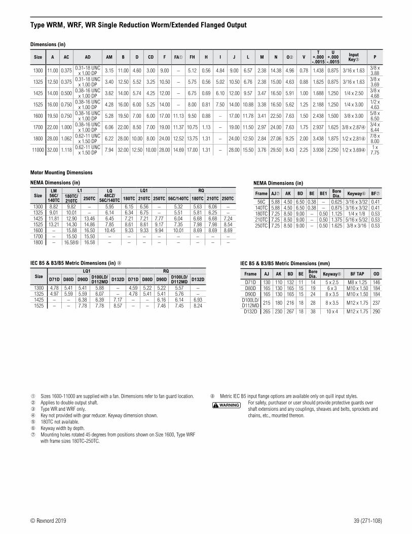
© Rexnord 2019 39 (271-108)
Type WRM, WRF, WR Single Reduction Worm/Extended Flanged Output
Dimensions (in)
Size A AC AD AM B D CD F FA➀ FH H I J L M N O➁ VT
+.000 -.0015
U+.000 -.0015
Input Key➂ P
1300 11.00 0.375 0.31-18 UNC x 1.00 DP 3.15 11.00 4.60 3.00 9.00 – 5.12 0.56 4.84 9.00 6.57 2.38 14.38 4.96 0.78 1.438 0.875 3/16 x 1.63 3/8 x
3.88
1325 12.50 0.375 0.31-18 UNC x 1.00 DP 3.40 12.50 5.52 3.25 10.50 – 5.75 0.56 5.02 10.50 6.76 2.38 15.00 4.63 0.88 1.625 0.875 3/16 x 1.63 3/8 x
3.69
1425 14.00 0.500 0.38-16 UNC x 1.00 DP 3.62 14.00 5.74 4.25 12.00 – 6.75 0.69 6.10 12.00 9.57 3.47 16.50 5.91 1.00 1.688 1.250 1/4 x 2.50 3/8 x
4.68
1525 16.00 0.750 0.38-16 UNC x 1.00 DP 4.28 16.00 6.00 5.25 14.00 – 8.00 0.81 7.50 14.00 10.88 3.38 16.50 5.62 1.25 2.188 1.250 1/4 x 3.00 1/2 x
4.63
1600 19.50 0.750 0.38-16 UNC x 1.00 DP 5.28 19.50 7.00 6.00 17.00 11.13 9.50 0.88 – 17.00 11.78 3.41 22.50 7.63 1.50 2.438 1.500 3/8 x 3.00 5/8 x
6.50
1700 22.00 1.000 0.38-16 UNC x 1.00 DP 6.06 22.00 8.50 7.00 19.00 11.37 10.75 1.13 – 19.00 11.50 2.97 24.00 7.63 1.75 2.937 1.625 3/8 x 2.87➃ 3/4 x
6.44
1800 28.00 1.062 0.62-11 UNC x 1.50 DP 6.22 28.00 10.00 8.00 24.00 12.52 13.75 1.31 – 24.00 12.50 2.84 27.06 9.25 2.00 3.438 1.875 1/2 x 2.81➃ 7/8 x
8.00
11000 32.00 1.118 0.62-11 UNC x 1.50 DP 7.94 32.00 12.50 10.00 28.00 14.69 17.00 1.31 – 28.00 15.50 3.76 29.50 9.43 2.25 3.938 2.250 1/2 x 3.69➃ 1 x
7.75
Motor Mounting Dimensions
NEMA Dimensions (in)
SizeLM
56C/ 140TC
L1 LQ48CZ/
56C/140TC
LQ1 RQ 180TC/ 210TC 250TC 180TC 210TC 250TC 56C/140TC 180TC 210TC 250TC
1300 8.82 9.82 – 5.95 6.15 6.56 – 5.32 5.63 6.06 –1325 9.01 10.01 – 6.14 6.34 6.75 – 5.51 5.81 6.25 –1425 11.81 12.90 13.46 6.45 7.21 7.21 7.77 6.04 6.68 6.68 7.241525 13.21 14.30 14.86 7.85 8.61 8.61 9.17 7.35 7.98 7.98 8.541600 – 15.88 16.50 10.45 9.33 9.33 9.94 10.01 8.69 8.69 8.691700 – 15.50 15.50 – – – – – – – –1800 – 16.58➄ 16.58 – – – – – – – –
IEC B5 & B3/B5 Metric Dimensions (in) ➇
SizeLQ1 RQ
D71D D80D D90D D100LD/D112MD D132D D71D D80D D90D D100LD/
D112MD D132D
1300 4.78 5.41 5.41 5.88 – 4.59 5.22 5.22 5.57 –1325 4.97 5.59 5.59 6.07 – 4.78 5.41 5.41 5.76 –1425 – – 6.38 6.39 7.17 – – 6.16 6.14 6.931525 – – 7.78 7.78 8.57 – – 7.46 7.45 8.24
➀ Sizes 1600-11000 are supplied with a fan. Dimensions refer to fan guard location.➁ Applies to double output shaft.➂ Type WR and WRF only.➃ Key not provided with gear reducer. Keyway dimension shown.➄ 180TC not available.➅ Keyway width by depth.➆ Mounting holes rotated 45 degrees from positions shown on Size 1600, Type WRF
with frame sizes 180TC-250TC.
➇ Metric IEC B5 input flange options are available only on quill input styles.
WARNING For safety, purchaser or user should provide protective guards over shaft extensions and any couplings, sheaves and belts, sprockets and chains, etc., mounted thereon.
Frame AJ AK BD BE Bore Dia. Keyway➅ BF TAP OD
D71D 130 110 132 11 14 5 x 2.5 M8 x 1.25 146D80D 165 130 165 15 19 6 x 3 M10 x 1.50 184D90D 165 130 165 15 24 8 x 3.5 M10 x 1.50 184
D100LD/D112MD 215 180 216 18 28 8 x 3.5 M12 x 1.75 237
D132D 265 230 267 18 38 10 x 4 M12 x 1.75 290
NEMA Dimensions (in)
Frame AJ➆ AK BD BE BE1 Bore Dia. Keyway➅ BF➆
56C 5.88 4.50 6.50 0.38 – 0.625 3/16 x 3/32 0.41140TC 5.88 4.50 6.50 0.38 – 0.875 3/16 x 3/32 0.41180TC 7.25 8.50 9.00 – 0.50 1.125 1/4 x 1/8 0.53210TC 7.25 8.50 9.00 – 0.50 1.375 5/16 x 5/32 0.53250TC 7.25 8.50 9.00 – 0.50 1.625 3/8 x 3/16 0.53
IEC B5 & B3/B5 Metric Dimensions (mm)

40 (271-108) © Rexnord 2019
Selection GuideSolid Output Shaft Type Double Reduction Worm-Worm
Ratings: pages 45-49Dimensions: pages 56-57
Ratings: pages 45-49Dimensions: pages 54-55
Ratings: pages 45-49Dimensions: pages 58-59
Ratings: pages 45-49Dimensions: pages 56-57
Ratings: pages 45-49Dimensions: pages 54-55
Ratings: pages 45-49Dimensions: pages 58-59
Ratings: pages 45-49Dimensions: pages 56-57
Ratings: pages 45-49Dimensions: pages 54-55
Ratings: pages 45-49Dimensions: pages 58-59
MO
TOR
IZED
C-
FLAN
GE
FLEX
IBLE
CO
UPL
ING
INPU
T
MO
TOR
IZED
C-
FLAN
GE
QU
ILL
INPU
T
Type WBWM
Type WBWF
Type WBW
Type WOWF
Type WOW
Type WUWF ➀
Type WUW ➀
➀ Not a recommended mounting style. Contact Rexnord for selection assistance.
Additional accessories, options and assembly services are available. Contact Rexnord for details.
Stock Types Modified Stock Types
Using off-the-shelf accessories, stock types WBWM, WBWF and WBW can be field or factory- modified into a wide range of styles. See page 91 for details.
Type WOWM Type WUWM ➀
Horizontal BaseWorm Over
Horizontal BaseWorm Under
Double Reduction/Worm-Worm
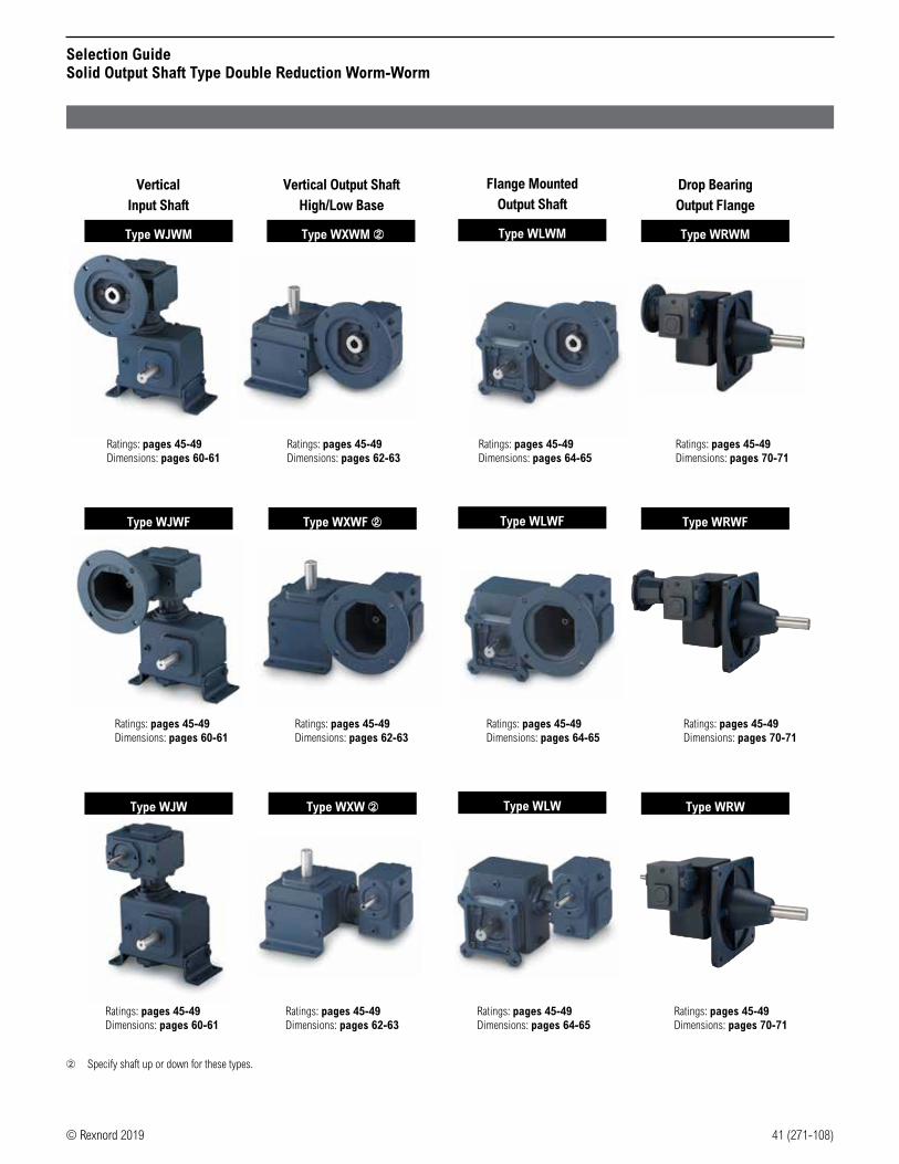
© Rexnord 2019 41 (271-108)
Selection GuideSolid Output Shaft Type Double Reduction Worm-Worm
Ratings: pages 45-49Dimensions: pages 62-63
Ratings: pages 45-49Dimensions: pages 64-65
Ratings: pages 45-49Dimensions: pages 60-61
Ratings: pages 45-49Dimensions: pages 62-63
Ratings: pages 45-49Dimensions: pages 60-61
Ratings: pages 45-49Dimensions: pages 64-65
Ratings: pages 45-49Dimensions: pages 62-63
Ratings: pages 45-49Dimensions: pages 60-61
Ratings: pages 45-49Dimensions: pages 64-65
Ratings: pages 45-49Dimensions: pages 70-71
Ratings: pages 45-49Dimensions: pages 70-71
Ratings: pages 45-49Dimensions: pages 70-71
Type WJWF
Type WJW
Type WXWF ➁
Type WXW ➁
Type WRWF
Type WRW
Type WJWM Type WXWM ➁ Type WRWM
Type WLWF
Type WLW
VerticalInput Shaft
Vertical Output ShaftHigh/Low Base
Drop BearingOutput Flange
Flange MountedOutput Shaft
Type WLWM
➁ Specify shaft up or down for these types.

42 (271-108) © Rexnord 2019
Selection GuideHollow Output Shaft Type Double Reduction Worm-Worm
Ratings: pages 45-49Dimensions: pages 68-69
Ratings: pages 45-49Dimensions: pages 66-67
Ratings: pages 45-49Dimensions: pages 68-69
Ratings: pages 45-49Dimensions: pages 66-67
Ratings: pages 45-49Dimensions: pages 68-69
Ratings: pages 45-49Dimensions: pages 66-67
NO
N-F
LAN
GED
INPU
T
MO
TOR
IZED
C-
FLAN
GE
FLEX
IBLE
CO
UPL
ING
INPU
T
MO
TOR
IZED
C-
FLAN
GE
QU
ILL
INPU
T
Type WBWQM
Type WBWQF
Type WBWQ
Stock Types Modified Stock Types
Using off-the-shelf accessories, stock types WBWQM, WBWQF and WBWQ can be field or factory-modified into a wide range of styles. See page 91 for details.
Type WLWQM
Type WLWQF
Type WLWQ
Flange MountedOutput Shaft

© Rexnord 2019 43 (271-108)
Double Reduction/Worm-WormQuick Selection Tables
How to UseBased on required output rpm and input motor horsepower, read across table for the appropriate reducer size. As a rule of thumb, use 1.00 service factor table for applications having uniform loads with up to 10 hours service duration per day. Use 1.25 service factor table for longer service or shock loading. These tables are to be considered as guides only. Refer to page 8 or contact Rexnord with specific application information.
1.00 Service Factor
Nominal Ratio ➀
OutputRPM
Input Horsepower @ 1750 RPM1/8 1/6 1/4 1/3 1/2 3/4 1 1-1/2 2 3 5 7-1/2 10 15 20 25
75 23.3 1133 1133 1154 1154 1206 1238 1262 1300 1325 1425 1525 1600 1800 1800 11000 11000100 17.5 1133 1133 1154 1154 1206 1238 1262 1300 1425 1425 1525 1600 1800 11000 11000150 11.7 1133 1154 1206 1206 1238 1262 1300 1325 1425 1525 1525 1800 11000 11000200 8.75 1154 1154 1206 1238 1262 1300 1325 1425 1425 1525 1700 1800 11000250 7.00 1154 1175 1206 1238 1262 1300 1325 1425 1525 1525 1800 11000 11000300 5.83 1154 1206 1238 1238 1300 1325 1425 1425 1525 1525 1800 11000 11000400 4.38 1206 1206 1238 1262 1300 1425 1425 1525 1525 1600 11000 11000500 3.50 1206 1238 1262 1300 1325 1425 1425 1525 1525 1800 11000600 2.92 1206 1238 1262 1300 1325 1425 1525 1525 1600 1800 11000750 2.33 1238 1238 1300 1300 1425 1425 1525 1525 1700 11000 11000900 1.94 1238 1262 1300 1325 1425 1425 1525 1525 1800 11000
1000 1.75 1238 1300 1300 1325 1425 1425 1525 1600 1800 110001200 1.46 1238 1300 1300 1325 1425 1525 1525 1700 1800 110001500 1.17 1300 1300 1325 1425 1425 1525 1600 1800 11000 110001800 0.972 1300 1300 1325 1425 1525 1525 1600 11000 110002400 0.729 1300 1300 1425 1425 1525 1525 1800 11000 110003000 0.583 1300 1300 1425 1425 1525 1525 1800 110003600 0.486 1300 1325 1425 1525 1525 1800 11000
1.25 Service Factor
Nominal Ratio ➀
OutputRPM
Input Horsepower @ 1750 RPM1/8 1/6 1/4 1/3 1/2 3/4 1 1-1/2 2 3 5 7-1/2 10 15 20
75 23.3 1133 1133 1154 1175 1206 1238 1300 1325 1425 1425 1525 1800 1800 11000 11000100 17.5 1133 1154 1154 1206 1238 1262 1300 1325 1425 1425 1525 1800 1800 11000150 11.7 1154 1154 1206 1238 1262 1300 1325 1425 1425 1525 1700 1800 11000200 8.75 1154 1206 1238 1238 1300 1325 1425 1425 1525 1525 1800 11000 11000250 7.00 1154 1206 1238 1262 1300 1325 1425 1425 1525 1525 1800 11000300 5.83 1175 1206 1238 1262 1300 1425 1425 1525 1525 1700 11000 11000400 4.38 1206 1238 1262 1300 1325 1425 1425 1525 1525 1800 11000500 3.50 1238 1238 1300 1300 1425 1425 1525 1525 1600 1800 11000600 2.92 1238 1238 1300 1325 1425 1425 1525 1525 1700 11000750 2.33 1238 1262 1300 1325 1425 1525 1525 1600 1800 11000900 1.94 1238 1300 1300 1325 1425 1525 1525 1800 1800 11000
1000 1.75 1262 1300 1300 1425 1425 1525 1525 1800 11000 110001200 1.46 1300 1300 1325 1425 1425 1525 1525 1800 11000 110001500 1.17 1300 1300 1425 1425 1525 1525 1800 11000 110001800 0.972 1300 1325 1425 1425 1525 1600 1800 11000 110002400 0.729 1300 1425 1425 1525 1525 1800 11000 110003000 0.583 1300 1425 1425 1525 1525 1800 11000 3600 0.486 1325 1425 1425 1525 1525 11000 11000
➀ Actual ratio combinations may vary from above depending on application and manufacturing requirements. Refer to page 50 for exact ratio of double reduction worm-worm gear reducers.
indicates a selection where a smaller reducer (1 case size) can be used with redesigned product due to rating increase.
indicates a selection where a smaller reducer (2 case sizes) can be used with redesigned product due to rating increase.
NOTE: This table is meant as a guide for reducer selections at specific motor horsepowers. Actual service factor may be greater than indicated. For actual service factors and maximum worm reducer ratings, refer to pages 7-8 and pages 45-49.

44 (271-108) © Rexnord 2019
Double Reduction/Worm-WormQuick Selection Tables
1.50 Service Factor
Nominal Ratio ➀
OutputRPM
Input Horsepower @ 1750 RPM1/8 1/6 1/4 1/3 1/2 3/4 1 1-1/2 2 3 5 7-1/2 10 15
75 23.3 1133 1154 1154 1206 1238 1262 1300 1425 1425 1525 1600 1800 1800 11000100 17.5 1154 1154 1206 1206 1238 1300 1300 1425 1425 1525 1600 1800 11000150 11.7 1154 1206 1206 1238 1262 1325 1325 1425 1525 1525 1800 11000 11000200 8.75 1154 1206 1238 1262 1300 1325 1425 1425 1525 1600 1800 11000250 7.00 1206 1206 1238 1262 1300 1425 1425 1525 1525 1700 11000 11000300 5.83 1206 1238 1262 1300 1325 1425 1425 1525 1525 1800 11000400 4.38 1238 1238 1300 1300 1425 1425 1525 1525 1600 1800 11000500 3.50 1238 1262 1300 1325 1425 1425 1525 1525 1800 11000600 2.92 1238 1262 1300 1325 1425 1525 1525 1700 1800 11000750 2.33 1262 1300 1325 1425 1425 1525 1525 1800 11000 11000900 1.94 1262 1300 1325 1425 1425 1525 1525 1800 11000
1000 1.75 1300 1300 1325 1425 1425 1525 1600 1800 110001200 1.46 1300 1300 1325 1425 1525 1525 1700 11000 110001500 1.17 1300 1325 1425 1425 1525 1600 1800 11000 110001800 0.972 1300 1425 1425 1525 1525 1800 11000 110002400 0.729 1425 1425 1525 1525 1525 1800 110003000 0.583 1425 1425 1525 1525 1525 11000 110003600 0.486 1425 1425 1525 1525 1800 11000
1.75 Service Factor
Nominal Ratio ➀
OutputRPM
Input Horsepower @ 1750 RPM1/8 1/6 1/4 1/3 1/2 3/4 1 1-1/2 2 3 5 7-1/2 10 15
75 23.3 1133 1154 1206 1206 1238 1300 1300 1425 1425 1525 1600 1800 11000 11000100 17.5 1154 1154 1206 1238 1262 1300 1325 1425 1425 1525 1700 11000 11000150 11.7 1154 1206 1238 1262 1300 1325 1425 1425 1525 1525 1800 11000200 8.75 1206 1206 1238 1262 1300 1425 1425 1525 1525 1700 11000 11000250 7.00 1206 1238 1262 1300 1325 1425 1425 1525 1525 1800 11000300 5.83 1206 1238 1262 1300 1325 1425 1525 1525 1600 1800 11000400 4.38 1238 1262 1300 1325 1425 1425 1525 1525 1800 11000500 3.50 1238 1262 1300 1325 1425 1525 1525 1700 1800 11000600 2.92 1262 1300 1325 1425 1425 1525 1525 1800 11000 11000750 2.33 1262 1300 1325 1425 1425 1525 1600 1800 11000900 1.94 1300 1300 1325 1425 1525 1525 1800 11000 11000
1000 1.75 1300 1300 1425 1425 1525 1525 1800 11000 110001200 1.46 1300 1325 1425 1425 1525 1525 1800 11000 110001500 1.17 1325 1425 1425 1525 1525 1800 11000 110001800 0.972 1325 1425 1425 1525 1525 11000 110002400 0.729 1425 1425 1525 1525 1700 11000 110003000 0.583 1425 1425 1525 1525 1800 11000 110003600 0.486 1425 1425 1525 1525 11000 11000
2.00 Service Factor
Nominal Ratio ➀
OutputRPM
Input Horsepower @ 1750 RPM1/8 1/6 1/4 1/3 1/2 3/4 1 1-1/2 2 3 5 7-1/2 10 15
75 23.3 1154 1154 1206 1238 1262 1300 1325 1425 1525 1525 1800 1800 11000100 17.5 1154 1154 1206 1238 1262 1300 1425 1425 1525 1525 1800 11000 11000150 11.7 1206 1206 1238 1262 1300 1325 1425 1525 1525 1700 11000 11000200 8.75 1206 1238 1262 1300 1325 1425 1425 1525 1525 1800 11000250 7.00 1206 1238 1262 1300 1325 1425 1525 1525 1600 1800 11000300 5.83 1238 1238 1300 1325 1425 1425 1525 1525 1700 11000 11000400 4.38 1238 1262 1300 1325 1425 1525 1525 1600 1800 11000500 3.50 1262 1300 1325 1425 1425 1525 1525 1800 11000 11000600 2.92 1262 1300 1325 1425 1525 1525 1600 1800 11000 11000750 2.33 1300 1300 1425 1425 1525 1525 1700 11000 11000900 1.94 1300 1325 1425 1425 1525 1525 1800 11000 11000
1000 1.75 1300 1325 1425 1425 1525 1600 1800 11000 110001200 1.46 1300 1325 1425 1425 1525 1700 1800 110001500 1.17 1325 1425 1425 1525 1600 1800 11000 110001800 0.972 1425 1425 1525 1525 1600 11000 110002400 0.729 1425 1425 1525 1525 1800 11000 110003000 0.583 1425 1425 1525 1525 1800 110003600 0.486 1425 1525 1525 1525 11000
➀ Actual ratio combinations may vary from above depending on application and manufacturing requirements. Refer to page 50 for exact ratio of double reduction worm-worm gear reducers.
indicates a selection where a smaller reducer (1 case size) can be used with redesigned product due to rating increase.
indicates a selection where a smaller reducer (2 case sizes) can be used with redesigned product due to rating increase.
NOTE: This table is meant as a guide for reducer selections at specific motor horsepowers. Actual service factor may be greater than indicated. For actual service factors and maximum worm reducer ratings, refer to pages 7-8 and pages 45-49.

© Rexnord 2019 45 (271-108)
Double Reduction/Worm-WormHorsepower and Torque Ratings
Nominal Ratio
Speed (RPM) Size 1133 Size 1154 Size 1175
Input OutputHorsepower Output
Torque(lb-in)
Horsepower Output Torque(lb-in)
Horsepower Output Torque(lb-in)Input Output Input Output Input Output
751750 23.3 0.215 0.141 381 0.391 0.242 654 0.415 0.287 7761170 15.6 0.154 0.097 390 0.286 0.168 678 0.295 0.197 797870 11.6 0.119 0.073 395 0.224 0.127 690 0.229 0.149 809
1001750 17.5 0.183 0.114 411 0.339 0.194 698 0.344 0.230 8271170 11.7 0.130 0.078 420 0.249 0.134 721 0.244 0.157 847870 8.70 0.103 0.059 425 0.196 0.101 734 0.191 0.118 858
1501750 11.7 0.122 0.073 395 0.233 0.125 674 0.235 0.150 8091170 7.80 0.085 0.050 400 0.166 0.085 690 0.166 0.101 820870 5.80 0.067 0.037 402 0.131 0.064 699 0.128 0.076 826
2001750 8.75 0.104 0.059 425 0.187 0.095 686 0.195 0.119 8581170 5.85 0.075 0.040 430 0.136 0.065 698 0.137 0.081 868870 4.35 0.058 0.030 432 0.105 0.049 705 0.107 0.060 874
2501750 7.00 0.090 0.046 417 0.158 0.073 660 0.165 0.096 8611170 4.68 0.064 0.031 422 0.113 0.050 671 0.115 0.065 871870 3.48 0.051 0.024 424 0.089 0.038 677 0.092 0.049 876
3001750 5.83 0.084 0.039 422 0.139 0.064 699 0.154 0.080 8641170 3.90 0.060 0.026 427 0.099 0.044 706 0.110 0.054 876870 2.90 0.046 0.020 430 0.078 0.033 711 0.085 0.041 882
4001750 4.38 0.062 0.030 432 0.111 0.049 705 0.114 0.061 8741170 2.93 0.043 0.020 435 0.081 0.033 711 0.081 0.040 879870 2.18 0.033 0.015 436 0.066 0.025 713 0.063 0.031 882
5001750 3.50 0.053 0.024 424 0.098 0.039 708 0.097 0.049 8771170 2.34 0.007 0.016 427 0.069 0.026 713 0.068 0.032 882870 1.74 0.029 0.012 428 0.053 0.019 715 0.054 0.024 884
6001750 2.92 0.048 0.020 430 0.086 0.033 711 0.090 0.041 8821170 1.95 0.034 0.013 432 0.065 0.022 714 0.066 0.027 888870 1.45 0.027 0.010 434 0.051 0.016 717 0.054 0.021 892
7501750 2.33 0.040 0.016 427 0.071 0.025 683 0.080 0.032 8861170 1.56 0.030 0.011 429 0.055 0.017 686 0.061 0.023 891870 1.16 0.027 0.008 429 0.046 0.013 689 0.048 0.017 893
9001750 1.94 0.036 0.013 432 0.067 0.020 665 0.068 0.027 8881170 1.30 0.028 0.009 434 0.048 0.014 668 0.050 0.018 893870 0.967 0.024 0.007 435 0.039 0.010 671 0.041 0.014 895
10001750 1.75 0.038 0.012 428 0.063 0.020 715 0.064 0.025 8841170 1.17 0.029 0.008 429 0.045 0.014 718 0.045 0.017 886870 0.870 0.020 0.006 430 0.037 0.010 719 0.035 0.013 887
12001750 1.46 0.034 0.010 434 0.052 0.017 717 0.059 0.021 8921170 0.975 0.025 0.007 435 0.041 0.011 719 0.043 0.014 895870 0.725 0.018 0.005 436 0.031 0.008 720 0.034 0.010 896
15001750 1.17 0.030 0.008 429 0.052 0.013 689 0.054 0.017 8931170 0.780 0.022 0.005 430 0.038 0.009 691 0.038 0.011 896870 0.580 0.018 0.004 431 0.032 0.007 692 0.029 0.009 897
18001750 0.972 0.028 0.007 435 0.045 0.010 601 0.048 0.014 8951170 0.650 0.018 0.005 436 0.032 0.007 603 0.038 0.010 897870 0.483 0.014 0.003 436 0.028 0.005 604 0.026 0.007 898
24001750 0.729 0.021 0.005 438 0.039 0.007 644 0.036 0.010 8871170 0.488 0.014 0.003 439 0.032 0.005 646 0.030 0.007 889870 0.363 0.014 0.003 439 0.027 0.004 647 0.024 0.006 890
30001750 0.583 0.021 0.004 437 0.033 0.006 605 0.032 0.008 8691170 0.390 0.014 0.003 438 0.028 0.004 607 0.023 0.006 871870 0.290 0.017 0.002 438 0.017 0.003 608 0.019 0.004 872
36001750 0.486 0.020 0.003 421 0.029 0.004 562 0.027 0.007 8541170 0.325 0.009 0.002 422 0.017 0.003 564 0.020 0.004 856870 0.242 0.011 0.002 422 0.017 0.002 566 0.020 0.003 857

46 (271-108) © Rexnord 2019
Double Reduction/Worm-WormHorsepower and Torque Ratings
Nominal Ratio
Speed (RPM) Size 1206 Size 1238 Size 1262
Input OutputHorsepower Output
Torque(lb-in)
Horsepower Output Torque(lb-in)
Horsepower Output Torque(lb-in)Input Output Input Output Input Output
751750 23.3 0.631 0.455 1230 0.979 0.707 1910 1.226 0.911 24611170 15.6 0.451 0.313 1266 0.702 0.489 1975 0.872 0.629 2540870 11.6 0.349 0.237 1285 0.546 0.370 2011 0.675 0.475 2583
1001750 17.5 0.537 0.365 1315 0.829 0.567 2041 1.048 0.736 26491170 11.7 0.384 0.251 1352 0.597 0.392 2109 0.755 0.508 2739870 8.7 0.299 0.189 1372 0.466 0.296 2146 0.588 0.385 2788
1501750 11.7 0.366 0.238 1284 0.572 0.373 2010 0.753 0.509 27401170 7.8 0.253 0.161 1303 0.397 0.253 2045 0.532 0.347 2803870 5.8 0.195 0.121 1313 0.306 0.190 2064 0.414 0.261 2836
2001750 8.75 0.305 0.190 1372 0.478 0.298 2145 0.602 0.387 27871170 5.85 0.216 0.129 1392 0.339 0.203 2182 0.426 0.263 2835870 4.35 0.167 0.097 1402 0.262 0.152 2201 0.000 0.197 2860
2501750 7.00 0.252 0.151 1363 0.405 0.240 2160 0.501 0.309 27791170 4.68 0.180 0.103 1381 1.276 0.164 2195 0.356 0.211 2824870 3.48 0.137 0.077 1390 0.225 0.123 2213 0.276 0.158 2848
3001750 5.83 0.222 0.128 1392 0.346 0.201 2182 0.436 0.261 28351170 3.90 0.158 0.087 1405 0.248 0.137 2207 0.312 0.177 2868870 2.90 0.121 0.065 1412 0.193 0.102 2220 0.242 0.133 2885
4001750 4.38 0.179 0.098 1402 0.280 0.154 2201 0.353 0.200 28601170 2.92 0.126 0.065 1412 0.197 0.102 2220 0.249 0.133 2885870 2.18 0.099 0.049 1417 0.156 0.078 2230 0.196 0.101 2898
5001750 3.50 0.154 0.078 1408 0.241 0.123 2212 0.303 0.160 28751170 2.34 0.108 0.052 1416 0.169 0.081 2227 0.215 0.106 2895870 1.74 0.085 0.038 1420 0.133 0.060 2235 0.167 0.078 2905
6001750 2.92 0.134 0.065 1412 0.213 0.101 2205 0.253 0.127 27521170 1.95 0.098 0.044 1419 0.154 0.069 2224 0.171 0.079 2568870 1.45 0.078 0.033 1422 0.119 0.051 2234 0.125 0.055 2376
7501750 2.33 0.114 0.051 1409 0.181 0.081 2217 0.219 0.105 28711170 1.56 0.087 0.036 1417 0.137 0.057 2232 0.166 0.073 2887870 1.16 0.068 0.027 1422 0.108 0.043 2240 0.133 0.055 2895
9001750 1.94 0.100 0.043 1413 0.159 0.067 2224 0.189 0.086 28481170 1.30 0.076 0.029 1420 0.118 0.046 2237 0.141 0.059 2863870 0.967 0.062 0.022 1424 0.095 0.035 2244 0.112 0.044 2871
10001750 1.75 0.099 0.041 1420 0.152 0.062 2175 0.156 0.066 23091170 1.17 0.072 0.027 1424 0.099 0.038 1989 0.050 0.040 2107870 0.870 0.056 0.020 1426 0.075 0.026 1840 0.076 0.028 1960
12001750 1.46 0.088 0.034 1418 0.139 0.053 2234 0.125 0.048 20291170 0.975 0.061 0.022 1423 0.100 0.035 2244 0.081 0.029 1882870 0.725 0.049 0.016 1426 0.076 0.025 2249 0.057 0.019 1733
15001750 1.17 0.076 0.027 1421 0.119 0.043 2240 0.113 0.042 22091170 0.780 0.056 0.018 1426 0.087 0.029 2248 0.077 0.026 2044870 0.580 0.042 0.014 1428 0.071 0.021 2252 0.058 0.018 1885
18001750 0.972 0.068 0.023 1424 0.111 0.036 2244 0.107 0.038 23651170 0.650 0.053 0.016 1427 0.085 0.025 2250 0.075 0.024 2184870 0.483 0.040 0.011 1429 0.066 0.018 2253 0.052 0.016 2010
24001750 0.729 0.056 0.016 1425 0.087 0.025 2244 0.096 0.028 25631170 0.488 0.043 0.011 1429 0.069 0.018 2250 0.070 0.019 2336870 0.363 0.035 0.009 1431 0.062 0.014 2254 0.053 0.014 2152
30001750 0.583 0.053 0.013 1381 0.080 0.021 2206 0.091 0.026 26911170 0.390 0.040 0.009 1384 0.057 0.014 2212 0.061 0.016 2456870 0.290 0.028 0.007 1386 0.047 0.011 2215 0.048 0.011 2253
36001750 0.486 0.048 0.011 1378 0.064 0.017 2090 0.084 0.022 27411170 0.325 0.034 0.007 1381 0.042 0.010 2095 0.055 0.013 2748870 0.242 0.028 0.005 1383 0.037 0.008 2098 0.048 0.010 2752

© Rexnord 2019 47 (271-108)
Nominal Ratio
Speed (RPM) Size 1300 Size 1325
Input OutputHorsepower Output
Torque(lb-in)
Horsepower Output Torque(lb-in)Input Output Input Output
751750 23.3 1.811 1.338 3615 2.005 1.482 40021170 15.6 1.312 0.932 3764 1.569 1.109 4481870 11.6 1.031 0.708 3846 1.251 0.859 4669
1001750 17.5 1.528 1.063 3830 1.984 1.405 50591170 11.7 1.108 0.741 3990 1.528 1.038 5592870 8.70 0.871 0.563 4078 1.214 0.796 5763
1501750 11.7 1.075 0.714 3844 1.537 0.973 52431170 7.80 0.766 0.486 3925 1.136 0.679 5485870 5.80 0.598 0.365 3968 0.901 0.517 5617
2001750 8.75 0.904 0.566 4076 1.208 0.768 55341170 5.85 0.649 0.386 4163 0.870 0.525 5658870 4.35 0.510 0.291 4210 0.681 0.395 5723
2501750 7.00 0.770 0.458 4128 1.016 0.617 55571170 4.68 0.557 0.314 4213 0.735 0.423 5675870 3.48 0.437 0.236 4258 0.576 0.319 5737
3001750 5.83 0.638 0.365 3967 0.931 0.517 56151170 3.90 0.462 0.248 4010 0.680 0.356 5747870 2.90 0.361 0.186 4032 0.534 0.268 5818
4001750 4.38 0.549 0.294 4209 0.735 0.399 57221170 2.92 0.389 0.196 4254 0.523 0.266 5786870 2.18 0.313 0.149 4278 0.420 0.203 5820
5001750 3.50 0.466 0.236 4257 0.591 0.302 54401170 2.34 0.330 0.157 4301 0.414 0.197 5400870 1.74 0.259 0.117 4324 0.307 0.139 5168
6001750 2.92 0.409 0.195 4235 0.571 0.268 58171170 1.95 0.297 0.132 4279 0.419 0.182 5886870 1.45 0.234 0.099 4302 0.329 0.136 5922
7501750 2.33 0.359 0.157 4301 0.484 0.214 58581170 1.56 0.274 0.110 4331 0.370 0.150 5914870 1.16 0.221 0.083 4347 0.294 0.113 5943
9001750 1.94 0.315 0.129 4279 0.440 0.177 58861170 1.30 0.234 0.089 4309 0.330 0.122 5933870 0.967 0.191 0.067 4324 0.265 0.092 5958
10001750 1.75 0.314 0.123 4324 0.411 0.165 57761170 1.17 0.234 0.083 4346 0.301 0.111 5827870 0.870 0.187 0.062 4358 0.240 0.084 5854
12001750 1.46 0.277 0.102 4302 0.378 0.136 57311170 0.975 0.200 0.067 4324 0.258 0.085 5503870 0.725 0.156 0.048 4336 0.192 0.058 5191
15001750 1.17 0.206 0.067 3537 0.282 0.093 49051170 0.780 0.148 0.043 3395 0.201 0.059 4684870 0.580 0.111 0.031 3223 0.154 0.042 4444
18001750 0.972 0.193 0.059 3746 0.221 0.067 42211170 0.650 0.145 0.040 3580 0.169 0.045 4045870 0.483 0.105 0.027 3375 0.122 0.030 3822
24001750 0.729 0.173 0.046 4136 0.183 0.051 45651170 0.488 0.133 0.031 3900 0.141 0.034 4318870 0.363 0.107 0.023 3666 0.116 0.026 4077
30001750 0.583 0.168 0.041 4261 0.182 0.046 48231170 0.390 0.149 0.027 4276 0.129 0.029 4553870 0.290 0.101 0.020 4284 0.102 0.020 4285
36001750 0.486 0.151 0.033 4128 0.174 0.040 50641170 0.325 0.100 0.020 4142 0.112 0.023 4767870 0.242 0.090 0.016 4150 0.088 0.017 4465
Double Reduction/Worm-WormHorsepower and Torque Ratings

48 (271-108) © Rexnord 2019
Nominal Ratio
Speed (RPM) Size 1425 Size 1525 Size 1600
Input OutputHorsepower Output
Torque(lb-in)
Horsepower Output Torque(lb-in)
Horsepower Output Torque(lb-in)Input Output Input Output Input Output
751750 23.3 3.845 2.941 7945 7.099 5.472 14782 9.100 7.135 192711170 15.6 3.001 2.215 8949 5.800 4.296 17357 6.941 5.231 21133870 11.6 2.413 1.731 9405 4.802 3.446 18723 5.581 4.086 22202
1001750 17.5 3.820 2.815 10140 7.206 5.269 18977 8.665 5.947 214171170 11.7 2.978 2.099 11307 5.470 3.822 20589 6.123 4.355 23458870 8.70 2.377 1.625 11772 4.421 2.968 21503 4.945 3.400 24627
1501750 11.7 2.870 2.029 10931 5.336 3.724 20059 5.945 4.357 234711170 7.80 2.182 1.479 11950 4.273 2.845 22985 3.283 3.093 24995870 5.80 1.715 1.127 12241 3.477 2.234 24280 3.498 2.378 25843
2001750 8.75 2.347 1.612 11613 4.438 2.983 21487 4.954 3.416 246071170 5.85 1.689 1.109 11953 3.258 2.082 22429 2.728 2.397 25821870 4.35 1.309 0.838 12136 2.565 1.583 22940 2.886 1.828 26485
2501750 7.00 1.960 1.290 11619 3.834 2.424 21825 4.251 2.759 248411170 4.68 1.417 0.890 11941 2.827 1.699 22777 2.354 1.943 26061870 3.48 1.104 0.673 12113 2.251 1.294 23294 2.514 1.484 26728
3001750 5.83 1.704 1.100 11955 3.230 2.065 22434 3.607 2.376 258211170 3.90 1.226 0.754 12191 2.358 1.429 23097 2.627 1.652 26689870 2.90 0.949 0.567 12316 1.850 1.079 23452 2.057 1.249 27151
4001750 4.38 1.376 0.847 12132 2.660 1.601 22932 3.009 1.848 264731170 2.92 0.973 0.567 12313 1.895 1.079 23443 2.138 1.249 27140870 2.18 0.770 0.433 12408 1.512 0.828 23715 1.722 0.960 27495
5001750 3.50 1.149 0.679 12219 2.249 1.290 23238 2.516 1.492 268721170 2.34 0.787 0.441 12092 1.591 0.863 23655 1.801 1.000 27416870 1.74 0.577 0.312 11570 1.235 0.644 23875 0.140 0.747 27704
6001750 2.92 0.936 0.524 11386 1.951 1.079 23447 2.242 1.249 271511170 1.95 0.665 0.348 11241 1.411 0.736 23798 1.629 0.854 27602870 1.45 0.490 0.248 10760 1.100 0.552 23982 1.286 0.641 27844
7501750 2.33 0.873 0.446 12217 1.686 0.869 23807 1.929 0.999 273861170 1.56 0.650 0.314 12369 1.270 0.613 24161 1.458 0.707 27851870 1.16 0.512 0.237 12448 1.004 0.464 24348 1.159 0.535 28094
9001750 1.94 0.766 0.371 12293 1.516 0.725 24049 1.622 0.827 274341170 1.30 0.566 0.256 12420 1.121 0.503 24406 1.218 0.575 27900870 0.967 0.446 0.192 12487 0.884 0.379 24594 0.969 0.433 28144
10001750 1.75 0.749 0.351 12273 1.467 0.687 24072 1.611 0.792 277371170 1.17 0.538 0.236 12417 1.059 0.463 24342 1.171 0.535 28088870 0.870 0.425 0.178 12492 0.841 0.350 24484 0.930 0.404 28269
12001750 1.46 0.665 0.295 12389 1.325 0.579 24316 1.403 0.659 276831170 0.975 0.465 0.192 12485 0.931 0.378 24589 1.000 0.433 28138870 0.725 0.357 0.139 12535 0.713 0.275 24731 0.770 0.315 28320
15001750 1.17 0.538 0.226 11853 0.938 0.393 20658 1.240 0.535 280881170 0.780 0.361 0.141 11117 0.654 0.254 19979 0.903 0.360 28328870 0.580 0.271 0.099 10357 0.497 0.180 18904 0.720 0.271 28453
18001750 0.972 0.439 0.168 10608 0.915 0.356 22441 1.000 0.401 252731170 0.650 0.320 0.111 10016 0.666 0.238 21472 0.767 0.283 25490870 0.483 0.230 0.075 9412 0.480 0.160 20158 0.586 0.203 25602
24001750 0.729 0.371 0.129 11595 0.785 0.267 24026 0.839 0.310 278931170 0.488 0.272 0.086 10782 0.618 0.192 24206 0.694 0.223 28130870 0.363 0.219 0.064 10044 0.534 0.154 24300 0.594 0.179 28253
30001750 0.583 0.360 0.116 12214 0.756 0.227 23866 0.750 0.255 267921170 0.390 0.269 0.078 12271 0.557 0.153 24044 0.602 0.171 27020870 0.290 0.220 0.059 12301 0.450 0.115 24137 0.482 0.129 27138
36001750 0.486 0.315 0.094 11816 0.688 0.186 23474 0.653 0.183 230671170 0.325 0.213 0.057 11870 0.456 0.113 23649 0.436 0.111 23264870 0.242 0.184 0.045 11897 0.400 0.090 23741 0.373 0.089 23366
Double Reduction/Worm-WormHorsepower and Torque Ratings

© Rexnord 2019 49 (271-108)
Nominal Ratio
Speed (RPM) Size 1700 Size 1800 Size 11000
Input OutputHorsepower Output
Torque(lb-in)
Horsepower Output Torque(lb-in)
Horsepower Output Torque(lb-in)Input Output Input Output Input Output
751750 23.3 9.13 7.55 20601 15.50 13.00 35507 26.50 22.50 610101170 15.6 7.69 6.16 25161 12.00 9.78 39931 20.40 16.90 68348870 11.6 6.80 5.32 29208 9.57 7.61 41787 16.30 13.20 72067
1001750 17.5 9.13 7.22 27535 12.60 10.10 38575 20.80 17.00 643631170 11.7 7.04 5.37 30607 9.55 7.40 42191 16.20 12.80 72302870 8.70 5.61 4.16 31879 7.64 5.76 44192 13.00 10.00 76335
1501750 11.7 7.25 5.53 30621 9.82 7.62 42212 16.50 13.00 720691170 7.80 5.31 3.90 32270 7.23 5.41 44811 12.30 9.38 77678870 5.80 4.18 2.98 33158 5.71 4.15 46217 9.78 7.25 80749
2001750 8.75 5.81 4.32 31857 7.92 5.98 44158 13.50 10.30 762611170 5.85 4.21 3.00 33136 5.75 4.18 46181 9.93 7.31 80671870 4.35 3.29 2.28 33817 4.50 3.18 47264 7.83 5.59 83051
2501750 7.00 4.90 3.54 31238 6.61 4.88 43010 11.30 8.45 745711170 4.68 3.55 2.46 32432 4.80 3.40 44863 8.31 5.96 78638870 3.48 2.77 1.86 33067 3.76 2.58 45852 6.55 4.55 80828
3001750 5.83 4.27 2.99 33136 5.82 4.17 46181 10.10 7.29 806711170 3.90 3.06 2.05 34024 4.19 2.87 47593 7.29 5.06 83779870 2.90 2.39 1.55 34489 3.26 2.17 48334 5.71 3.84 85419
4001750 4.38 3.41 2.29 33805 4.65 3.20 47245 8.12 5.62 830111170 2.92 2.43 1.56 34477 3.33 2.19 48316 5.85 3.87 85377870 2.18 2.10 1.17 34830 2.59 1.65 48879 4.58 2.92 86628
5001750 3.50 2.86 1.85 34209 3.88 2.60 45835 6.89 4.57 844311170 2.34 2.04 1.26 34752 2.78 1.77 46812 4.96 3.13 86351870 1.74 1.59 0.94 35036 2.16 1.33 47326 3.88 2.35 87361
6001750 2.92 2.53 1.56 34477 3.43 2.18 48316 6.03 3.86 853771170 1.95 1.81 1.06 34936 2.46 1.48 49049 4.34 2.63 87006870 1.45 1.42 0.79 35174 1.92 1.11 49429 3.40 1.97 87854
7501750 2.33 2.13 1.27 33682 2.87 1.77 46812 5.04 3.13 829641170 1.56 1.53 0.86 34109 2.05 1.20 47481 3.63 2.13 84459870 1.16 1.20 0.65 34331 1.60 0.90 47827 2.85 1.60 85236
9001750 1.94 1.73 1.01 32016 2.50 1.47 46627 4.13 2.49 793531170 1.30 1.24 0.68 32391 1.80 0.99 46972 2.97 1.69 80681870 0.967 0.97 0.51 32585 1.42 0.74 47150 2.33 1.27 81371
10001750 1.75 1.73 0.95 35031 2.34 1.33 49201 4.21 2.37 873441170 1.17 1.24 0.64 35308 1.68 0.90 49644 3.05 1.60 88332870 0.870 0.98 0.48 35452 1.32 0.67 49874 2.41 1.20 88847
12001750 1.46 1.52 0.79 35168 2.05 1.12 49420 3.73 1.98 878321170 0.975 1.10 0.53 35402 1.48 0.75 49793 2.72 1.34 88666870 0.725 0.87 0.40 35522 1.16 0.56 49986 2.15 1.00 89097
15001750 1.17 1.28 0.65 34325 1.71 0.90 47819 3.13 1.61 852161170 0.780 0.93 0.44 34542 1.23 0.61 48159 2.28 1.09 85980870 0.580 0.74 0.33 34654 0.98 0.45 48334 1.81 0.81 86375
18001750 0.972 1.04 0.51 32580 1.29 0.67 42944 2.56 1.28 813531170 0.650 0.76 0.34 32770 0.93 0.45 43207 1.86 0.86 82031870 0.483 0.60 0.26 32868 0.74 0.34 43342 1.48 0.64 82381
24001750 0.729 0.90 0.39 33661 1.20 0.54 46987 2.17 0.96 833141170 0.488 0.65 0.26 33868 0.87 0.37 47314 1.59 0.65 84037870 0.363 0.53 0.20 33975 0.69 0.27 47482 1.26 0.49 84411
30001750 0.583 0.76 0.30 32512 1.02 0.42 45708 1.83 0.78 808361170 0.390 0.55 0.20 32710 0.74 0.29 46025 1.35 0.51 81535870 0.290 0.45 0.15 32813 0.60 0.21 46189 1.08 0.38 81896
36001750 0.486 0.60 0.23 29307 0.80 0.32 41112 1.46 0.57 732841170 0.325 0.44 0.15 29473 0.58 0.21 41376 1.07 0.38 73877870 0.242 0.35 0.11 29558 0.47 0.16 41512 0.86 0.29 74183
Double Reduction/Worm-WormHorsepower and Torque Ratings

50 (271-108) © Rexnord 2019
Double Reduction (Worm-Worm) Exact Ratio Combinations
Nominal Total
Rating
Gear Reducer Size1133 1154 1175 1206 1238 1262 1300
Primary1133
Secondary1133
Primary1133
Secondary1154
Primary1133
Secondary1175
Primary1133
Secondary1206
Primary1133
Secondary1238
Primary1133
Secondary1262
Primary1175
Secondary1300
75 5 15 5 15 5 15 5 15 5 15 5 15 5 15100 5 20 5 20 5 20 5 20 5 20 5 20 5 20150 10 15 7.5 20 10 15 10 15 10 15 7.5 20 10 15200 10 20 10 20 10 20 10 20 10 20 10 20 10 20250 10 25 10 25 10 25 10 25 10 25 10 25 10 25300 10 30 15 20 10 30 15 20 15 20 15 20 20 15400 20 20 20 20 20 20 20 20 20 20 20 20 20 20500 20 25 25 20 25 20 25 20 25 20 25 20 20 25600 20 30 30 20 20 30 30 20 20 30 30 20 20 30750 30 25 30 25 25 30 25 30 25 30 30 25 30 25900 30 30 30 30 30 30 30 30 30 30 30 30 30 30
1000 40 25 50 20 50 20 50 20 50 20 50 20 40 251200 40 30 60 20 40 30 40 30 40 30 60 20 40 301500 60 25 60 25 50 30 50 30 50 30 60 25 60 251800 60 30 60 30 60 30 60 30 60 30 60 30 60 302400 60 40 60 40 60 40 60 40 60 40 60 40 60 403000 60 50 60 50 60 50 60 50 60 50 60 50 60 503600 60 60 60 60 60 60 60 60 60 60 60 60 60 60
Double Reduction (Worm-Worm) Exact Ratio Combinations continued
Nominal Total
Rating
Gear Reducer Size1325 1425 1525 1600 1700 1800 11000
Primary1175
Secondary1325
Primary1206
Secondary1425
Primary1262
Secondary1525
Primary1325
Secondary1600
Primary1325
Secondary1700
Primary1425
Secondary1800
Primary1525
Secondary11000
75 5 15 5 15 5.17 15 5.17 15 5.17 14.67 5.17 14.67 5.13 14.67100 5 20 5 20 5.17 20 5.17 20 5.17 20.5 5.17 20.5 5.13 20.5150 5 30 7.5 20 7.5 20 10 15 7.5 20.5 7.5 20.5 10 14.67200 10 20 10 20 10 20 10 20 10 20.5 10 20.5 10 20.5250 10 25 10 25 10 25 10 25 10 24.5 10 24.5 10 24.5300 10 30 15 20 15 20 20 15 15 20.5 15 20.5 20 14.67400 20 20 20 20 20 20 20 20 20 20.5 20 20.5 20 20.5500 25 20 25 20 25 20 25 20 25 20.5 20 24.5 25 20.5600 20 30 30 20 30 20 30 20 30 20.5 30 20.5 30 20.5750 25 30 25 30 30 25 30 25 30 24.5 30 24.5 30 24.5900 30 30 30 30 30 30 60 15 30 29.5 30 29.5 60 14.67
1000 25 40 25 40 40 25 50 20 50 20.5 40 24.5 50 20.51200 40 30 40 30 40 30 60 20 60 20.5 40 29.5 60 20.51500 50 30 50 30 60 25 60 25 60 24.5 60 24.5 60 24.51800 60 30 60 30 60 30 60 30 60 29.5 60 29.5 60 29.52400 60 40 60 40 60 40 60 40 60 40 60 40 60 403000 60 50 60 50 60 50 60 50 60 50 60 50 60 503600 60 60 60 60 60 60 60 60 60 60 60 60 60 60
NOTE: Exact ratios are listed. Actual ratio combinations supplied may vary from above depending on application and manufacturing requirements. For exact total of double reduction package, multiply primary stage ratio by secondary stage ratio.
Exact Ratio Combinations and Hollow Shaft Bore Sizes
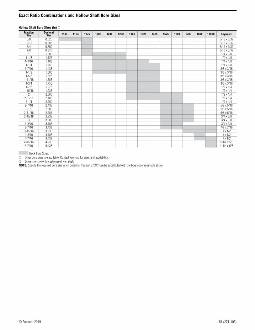
© Rexnord 2019 51 (271-108)
Hollow Shaft Bore Sizes (in) ➀Fraction
SizeDecimal
Size 1133 1154 1175 1206 1238 1262 1300 1325 1425 1525 1600 1700 1800 11000 Keyway➁
5/8 0.625 3/16 x 3/3211/16 0.688 3/16 x 3/32
3/4 0.750 3/16 x 3/327/8 0.875 3/16 x 3/321 1.000 1/4 x 1/8
1-1/8 1.125 1/4 x 1/81-3/16 1.188 1/4 x 1/81-1/4 1.250 1/4 x 1/81-7/16 1.438 3/8 x 3/161-1/2 1.500 3/8 x 3/161-5/8 1.625 3/8 x 3/16
1-11/16 1.688 3/8 x 3/161-3/4 1.750 3/8 x 3/161-7/8 1.875 1/2 x 1/4
1-15/16 1.938 1/2 x 1/42 2.000 1/2 x 1/4
2- 3/16 2.188 1/2 x 1/42-1/4 2.250 1/2 x 1/42-7/16 2.438 5/8 x 5/162-1/2 2.500 5/8 x 5/16
2-11/16 2.688 5/8 x 5/162-15/16 2.938 3/4 x 3/8
3 3.000 3/4 x 3/83-3/16 3.188 3/4 x 3/83-7/16 3.438 7/8 x 7/16
3-15/16 3.938 1 x 1/24-3/16 4.188 1 x 1/24-7/16 4.438 1 x 1/2
4-15/16 4.938 1-1/4 x 5/85-7/16 5.438 1-1/4 x 5/8
Stock Bore Sizes.➀ Other bore sizes are available. Contact Rexnord for sizes and availability.➁ Dimensions refer to customer-driven shaft.NOTE: Specify the required bore size when ordering. The suffix “XX” can be substituted with the bore code from table above.
Exact Ratio Combinations and Hollow Shaft Bore Sizes

52 (271-108) © Rexnord 2019
Weights
Double Reduction Worm-Worm Approximate Weights➀ (lb)
Reducer TypeReducer Size
1133 1154 1175 1206 1238 1262 1300 1325 1425 1525 1600 1700 1800 11000Solid Output Shaft
WBWM 34 38 41 46 62 73 89 96 175 303 406 482 728 1151WBWF 39 43 46 51 67 78 91 98 176 304 407 493 736 1158WBW 34 38 41 46 62 73 86 93 171 299 402 478 718 1136
WOWM & WUWM 36 41 44 50 66 79 95 105 189 323 437 523 776 1227WOWF & WUWF 41 46 49 55 71 84 97 107 190 324 438 534 784 1234WOW & WUW 36 41 44 50 66 79 92 102 185 319 433 519 766 1212
WJWM 35 39 43 49 65 78 95 102 185 318 – – – –WJWF 40 44 48 54 70 83 97 104 186 319 – – – –WJW 35 39 43 49 65 78 92 99 181 314 – – – –
WXWM 36 41 44 53 69 82 99 109 195 328 442 553 806 1307WXWF 41 46 49 58 74 87 101 111 196 329 443 564 814 1314WXW 36 41 44 53 69 82 96 106 191 324 438 549 796 1292
WLWM 35 39 43 49 65 77 99 106 190 333 444 497 746 1172WLWF 40 44 48 54 70 82 101 108 191 334 445 508 754 1179WLW 35 39 43 49 65 77 96 103 186 329 440 493 736 1157
WRWM – – – – – – 99 106 205 334 448 647 930 1431WRWF – – – – – – 101 108 206 335 449 658 938 1438WRW – – – – – – 96 103 201 330 444 643 920 1406
Hollow Output ShaftWBWQM 35 38 42 47 64 72 90 98 178 303 406 482 728 1151WBWQF 40 42 46 51 68 76 92 100 179 304 407 493 736 1158WBWQ 35 38 42 47 64 72 87 95 174 299 402 478 718 1136
WLWQM 36 39 44 50 67 76 100 108 193 333 444 497 746 1172WLWQF 41 43 48 54 71 80 102 110 194 334 445 508 754 1179WLWQ 36 39 44 50 67 76 97 105 189 329 440 493 736 1157
➀ Weights include oil.
Accessories Approximate Weights (lb)
AccessoryReducer Size
1133 1154 1175 1206 1238 1262 1300 1325 1425 1525 1600 1700 1800 11000HOFK 2 3 3 4 4 6 6 9 14 20 31 41 48 76VIFK 1 1 2 3 3 5 6 6 10 15 – – – –VOFK 2 3 3 7 7 9 10 13 20 25 36 ➁ ➁ ➁OFK 1 1 2 3 3 4 10 10 15 30 38 ➁ ➁ ➁RB – 7 7 9 9 12 15 31 24 15 – – – –
TRK 5 5 5 5 5 5 5 5 5 8 8 – – –Coupling Input C-Flange Kits
48CZ, 56C, 140TC 7 7 7 7 8 8 11 11 14 16 – – – –180TC-210TC – – – – 11 11 11 11 16 18 22 30 30 –
250TC – – – – – – – 28 30 30 32 34 36 –
➁ This accessory must be assembled at the factory. It is not available as a kit for field installation.
Weights, Dimensions and Assemblies

© Rexnord 2019 53 (271-108)
NOTES:
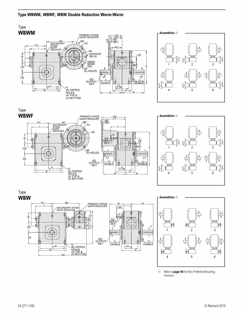
54 (271-108) © Rexnord 2019
Type WBWM, WBWF, WBW Double Reduction Worm-Worm
SECONDARYSTAGEGEARREDUCER
BC
JB
K
R
I
D2
CD
(2)HOLES3/8-16
LQLQ1
RQ
CE
C
AK
AJBD
GF
AN
H(8) TAPPEDHOLES(4) TOP &(4) BOTTOM
BF(4) HOLES
NEMABOREDIA.
OSQ.OUTPUT
KEY USABLE
TO*
N
USABLE
D1
T
PRIMARY STAGEGEAR REDUCER
BE1BE
FC
Type
WBWM
Type
WBWF
Type
WBW
SECONDARY STAGEGEAR REDUCER
BC
JB
K
D2
I
CD
R
N N
C
G
T T
FA
H(8) TAPPEDHOLES(4) TOP &(4) BOTTOM
SQ.OUTPUT
KEY USABLEO
USABLEO*
LML1
LBD
AK
AJ
BF(4) HOLES
PRIMARY STAGEGEAR REDUCER
SQ.INPUTKEY
U
BEBE1
D1
CE
FC
BJ
BC
BJ
K
SECONDARY STAGEGEAR REDUCER
I
D2
R
CD
LN
AG
F
M
C1
C
H(8) TAPPEDHOLES(4) TOP &(4) BOTTOM
D1
CE
T
SQ.OUTPUT
KEY USABLEO
SQ.INPUTKEY
U
PRIMARY STAGEGEAR REDUCER
N
T
O*USABLE
FC
➀ Refer to page 94 for Non-Preferred Mounting Positons.
1
4
2
5
3
6
Assemblies ➀
1
4
2
5
3
6
Assemblies ➀
1
4
2
5
3
6
Assemblies ➀

© Rexnord 2019 55 (271-108)
Type WBWM, WBWF, WBW Double Reduction Worm-Worm
Dimensions (in)
Size A B BC BJ C CD CE C1 D1 D2 F FC➀ GH
I J K L M N O O➁ RT
+.000 -.0015
U+.000 -.0015
Input Key➂
Output KeyTap Size Depth
1133 2.82 3.80 5.32 9.06 5.99 1.33 1.33 4.66 1.72 1.72 2.00 – 1.00 5/16-18 UNC 0.50 2.61 3.25 1.63 3.82 1.76 4.00 2.16 1.94 1.61 0.625 0.500 1/8 x 1.00 3/16 x 1.501154 3.44 4.88 5.85 10.13 6.38 1.54 1.33 4.66 1.72 1.91 2.75 – 1.38 5/16-18 UNC 0.63 3.14 4.19 2.09 3.82 1.76 4.31 2.11 1.90 1.93 0.750 0.500 1/8 x 1.00 3/16 x 1.501175 3.56 5.06 5.94 10.32 6.75 1.75 1.33 4.66 1.72 2.06 2.75 – 1.38 5/16-18 UNC 0.63 3.24 4.19 2.09 3.82 1.76 4.31 2.05 1.84 1.94 0.875 0.500 1/8 x 1.00 3/16 x 1.381206 3.81 5.80 6.32 11.06 7.28 2.06 1.33 4.66 1.72 2.28 3.00 – 1.44 3/8-16 UNC 0.63 3.61 4.75 2.50 3.82 1.76 4.68 2.29 2.08 2.03 1.000 0.500 1/8 x 1.00 1/4 x 1.441238 4.06 6.12 6.44 11.35 7.81 2.38 1.33 4.66 1.72 2.50 2.88 – 1.44 3/8-16 UNC 0.69 3.77 5.00 2.50 3.82 1.76 5.14 2.66 2.44 2.06 1.125 0.500 1/8 x 1.00 1/4 x 1.751262 4.84 7.12 7.01 12.41 8.50 2.63 1.33 4.66 1.72 2.94 3.38 – 1.69 3/8-16 UNC 0.69 4.34 6.38 3.19 3.82 1.76 5.63 2.73 2.52 2.44 1.125 0.500 1/8 x 1.00 1/4 x 1.751300 5.25 8.12 7.86 14.12 9.94 3.00 1.75 5.38 2.06 3.25 4.00 – 2.00 7/16-14 UNC 0.88 4.84 7.00 3.50 4.45 1.76 6.75 3.60 3.36 2.63 1.250 0.625 3/16 x 1.38 1/4 x 1.751325 5.75 8.50 8.05 14.50 10.44 3.25 1.75 5.38 2.06 3.50 4.00 – 2.00 7/16-14 UNC 0.88 5.02 7.50 3.75 4.45 1.76 7.06 3.66 3.42 2.63 1.375 0.625 3/16 x 1.38 5/16 x 2.631425 6.13 10.25 9.18 16.69 12.78 4.25 2.06 6.38 2.28 4.44 5.00 – 2.50 5/8-11 UNC 1.00 6.10 8.50 4.25 4.82 1.76 8.12 4.50 4.21 2.69 1.875 0.625 3/16 x 1.38 1/2 x 3.061525 7.19 13.00 11.57 20.97 15.43 5.25 2.63 8.00 2.94 5.12 5.81 – 2.91 5/8-11 UNC 1.25 7.50 11.00 5.50 6.07 2.38 9.06 4.78 4.53 3.63 2.000 0.750 3/16 x 1.63 1/2 x 3.501600 8.13 14.25 13.30 23.82 18.38 6.00 3.25 9.38 3.50 6.50 6.38 10.24 3.19 5/8-11 UNC 1.00 – 12.75 6.38 6.76 2.38 10.00 4.65 4.65 4.00 2.250 0.875 3/16 x 1.63 5/8 x 4.00
1700 7.63 14.88 12.96 24.33 20.46 7.00 3.25 9.38 3.50 7.59 5.50 10.63 2.75 1-8 UNC 1.56 – 12.50 6.25 6.76 2.38 11.76 5.65 5.65 4.33 2.750 0.8753/16 x 1.75➃
5/8 x 4.00➃
1800 8.63 17.00 13.94 26.69 23.79 8.00 4.25 11.38 4.44 8.86 6.50 11.93 3.25 1-8 UNC 1.66 – 14.25 7.13 9.57 3.47 12.25 5.98 5.98 4.11 3.000 1.2503/4 x
2.88➃3/4 x
4.50➃
11000 9.53 20.88 17.05 32.74 29.24 10.00 5.25 14.00 5.12 10.36 6.88 14.34 3.44 1-1/4 -7 UNC 2.04 – 17.75 8.88 10.88 3.38 14.75 6.76 6.76 5.12 3.750 1.2501/4 x
3.00➃7/8 x
5.00➃
Motor Mounting Dimensions
NEMA Dimensions (in)
SizeLM L1 LQ
48CZ/ 56C/140TC
LQ1 RQ
48CZ56C/
140TC180TC/ 210TC
250TC 180TC 210TC 250TC48CZ/
56C/140TC180TC 210TC 250TC
1133 5.63 6.07 – – 3.46 – – – 3.09 – – –1154 5.63 6.07 – – 3.46 – – – 3.09 – – –1175 5.63 6.07 – – 3.46 – – – 3.09 – – –1206 5.63 6.07 – – 3.46 – – – 3.09 – – –1238 5.63 6.07 – – 3.46 – – – 3.09 – – –1262 5.63 6.07 – – 3.46 – – – 3.09 – – –1300 6.26 6.70 – – 4.09 – – – 3.59 – – –1325 6.26 6.70 – – 4.09 – – – 3.59 – – –1425 6.63 7.07 – – 4.46 – – – 4.06 – – –1525 – 8.32 9.32 – 5.19➄ 5.62 – – 4.82➄ 5.13 – –1600 – 9.01 10.01 – 6.14➄ 6.34 6.75 – 5.51➄ 5.81 6.25 –1700 – 9.01 10.01 – 6.14➄ 6.34 6.75 – 5.51➄ 5.81 6.25 –1800 – 11.81 12.90 13.46 6.45➄ 7.21 7.21 7.77 6.04➄ 6.68 6.68 7.2411000 – 13.21 14.30 14.86 7.85➄ 8.61 8.61 9.17 7.35➄ 7.98 7.98 8.54
IEC B5 & B3/B5 Metric Dimensions (in) ➇
SizeLQ1 RQ
D63D D71D D80D D90DD100LD/D112MD
D132D D63D D71D D80D D90DD100LD/D112MD
D132D
1133 2.62 2.65 2.89 – – – 2.45 2.47 2.71 – – –1154 2.62 2.65 2.89 – – – 2.45 2.47 2.71 – – –1175 2.62 2.65 2.89 – – – 2.45 2.47 2.71 – – –1206 2.62 2.65 2.89 – – – 2.45 2.47 2.71 – – –1238 2.62 2.65 2.89 – – – 2.45 2.47 2.71 – – –1262 2.62 2.65 2.89 – – – 2.45 2.47 2.71 – – –1300 3.25 3.28 3.52 – – – 2.95 2.97 3.21 – – –1325 3.25 3.28 3.52 – – – 2.95 2.97 3.21 – – –1425 3.62 3.65 3.89 – – – 3.43 3.44 3.68 – – –1525 – 4.28 4.90 4.90 5.30 – – 4.09 4.72 4.72 5.07 –1600 – 4.97 5.59 5.59 6.07 – – 4.78 5.41 5.41 5.76 –1700 – 4.97 5.59 5.59 6.07 – – 4.78 5.41 5.41 5.76 –1800 – – – 6.38 6.39 7.17 – – – 6.16 6.14 6.9311000 – – – 7.78 7.78 8.57 – – – 7.46 7.45 8.24
➀ Sizes 1600-11000 have extended cap. Dimensions refer to cap location.➁ Applies to double output shaft.➂ Type WBW and WBWF only.➃ Key not provided with gear reducer. Keyway dimension shown.➄ 48CZ not available.➅ Keyway width by depth.
➆ Mounting holes rotated 45 degrees from positions shown on Size 1600, Type WBWF with frame sizes 180TC-250TC.
➇ Metric IEC B5 input flange options are available only on quill input styles.
WARNING For safety, purchaser or user should provide protective guards over shaft extensions and any couplings, sheaves and belts, sprockets and chains, etc., mounted thereon.
Frame AJ AK BD BEBore Dia.
Keyway➅ BF TAP OD
D63D 115 95 117 10 11 4 x 2 M8 x 1.25 131D71D 130 110 132 11 14 5 x 2.5 M8 x 1.25 146D80D 165 130 165 15 19 6 x 3 M10 x 1.50 184D90D 165 130 165 15 24 8 x 3.5 M10 x 1.50 184
D100LD/D112MD
215 180 216 18 28 8 x 3.5 M12 x 1.75 237
D132D 265 230 267 18 38 10 x 4 M12 x 1.75 290
NEMA Dimensions (in)
Frame AJ AK BD BE BE1Bore Dia.
Keyway➅ BF➆
48CZ 3.75 3.00 4.36 0.38 – 0.500 1/8 x 1/16 0.2856C 5.88 4.50 6.50 0.38 – 0.625 3/16 x 3/32 0.41
140TC 5.88 4.50 6.50 0.38 – 0.875 3/16 x 3/32 0.41180TC 7.25 8.50 9.00 – 0.50 1.125 1/4 x 1/8 0.53210TC 7.25 8.50 9.00 – 0.50 1.375 5/16 x 5/32 0.53250TC 7.25 8.50 9.00 – 0.50 1.625 3/8 x 3/16 0.53
IEC B5 & B3/B5 Metric Dimensions (mm)

56 (271-108) © Rexnord 2019
Type WOWM, WOWF, WOW Double Reduction Worm-Worm/Worm Over
Type
WOWM
Type
WOWF
Type
WOW
➀ Refer to page 94 for Non-Preferred Mounting Positons.
1
4
2
5
3
6
Assemblies ➀
1
4
2
5
3
6
Assemblies ➀
1
4
2
5
3
6
Assemblies ➀
BJ
D2
I
CD
R(2)HOLES3/8-16
C
BDAJ
AKCE
RQ
LQ1LQ
BC
N
O
BF(4) HOLES
NEMABOREDIA.
KHDIA.(4) HOLES
SQ.OUTPUT
KEY USABLE
T
G
N
O*
FA
USABLE
V
D1T
BEBE1
PRIMARY STAGEGEAR REDUCER
SECONDARY STAGE GEARREDUCER
FC
D2
G
T
C
T
NNB
J
O
KHDIA.(4) HOLES
SQ.OUTPUT
KEYUSABLE
AFV
O*USABLE
I
R
CD
SQ.INPUT
KEY
U
L
L1LMPRIMARY STAGE
GEAR REDUCER
BF(4) HOLES
AK
AJBD
SECONDARYSTAGE GEARREDUCER
BCBEBE1
D1
CE
FC
JB
I
BJ
D2
R
CD
A
O
U
SQ.INPUTKEY
MN
LSECONDARY STAGEGEAR REDUCER
BC
C
HDIA.(4) HOLES
K
D1
CE
T
SQ.OUTPUT
KEYUSABLE
PRIMARY STAGEGEAR REDUCER
N
G
T
FV
USABLEO*
FC

© Rexnord 2019 57 (271-108)
Type WOWM, WOWF, WOW Double Reduction Worm-Worm/Worm Over
Dimensions (in)
Size A B BC BJ C CD CE C1 D1 D2 F FC➀ G H I J K L M N O O➁ R VT
+.000 -.0015
U+.000 -.0015
Input Key➂
Output Key
1133 4.24 5.37 5.32 9.85 6.52 1.33 1.33 4.66 1.72 2.25 3.31 – 1.66 0.34 2.61 4.37 2.19 3.82 1.76 4.00 2.16 1.94 1.61 0.53 0.625 0.500 1/8 x 1.00 3/16 x 1.501154 5.56 6.50 5.85 10.94 6.98 1.54 1.33 4.66 1.72 2.50 4.31 – 2.16 0.41 3.14 5.25 2.63 3.82 1.76 4.31 2.11 1.90 1.93 0.59 0.750 0.500 1/8 x 1.00 3/16 x 1.501175 5.75 6.99 5.94 11.28 7.44 1.75 1.33 4.66 1.72 2.75 4.50 – 2.25 0.41 3.24 5.75 2.88 3.82 1.76 4.31 2.05 1.84 1.94 0.69 0.875 0.500 1/8 x 1.00 3/16 x 1.381206 6.00 7.69 6.32 12.01 8.00 2.06 1.33 4.66 1.72 3.00 4.69 – 2.34 0.47 3.61 6.38 3.19 3.82 1.76 4.68 2.29 2.08 2.03 0.72 1.000 0.500 1/8 x 1.00 1/4 x 1.441238 6.19 8.37 6.44 12.48 8.56 2.38 1.33 4.66 1.72 3.25 4.88 – 2.44 0.49 3.77 7.06 3.53 3.82 1.76 5.14 2.66 2.44 2.06 0.75 1.125 0.500 1/8 x 1.00 1/4 x 1.751262 6.50 9.25 7.01 13.48 9.25 2.63 1.33 4.66 1.72 3.69 5.25 – 2.63 0.53 4.34 8.00 4.00 3.82 1.76 5.63 2.73 2.52 2.44 0.75 1.125 0.500 1/8 x 1.00 1/4 x 1.751300 7.50 10.00 7.86 15.08 9.94 3.00 1.75 5.38 2.06 4.00 5.88 – 2.94 0.53 4.84 8.44 4.22 4.35 1.76 6.75 3.60 3.36 2.63 0.75 1.250 0.625 3/16 x 1.38 1/4 x 1.751325 7.75 11.12 8.05 15.81 10.44 3.25 1.75 5.38 2.06 4.38 6.13 – 3.06 0.53 5.02 9.50 4.75 4.35 1.76 7.06 3.66 3.42 2.63 0.81 1.375 0.625 3/16 x 1.38 5/16 x 2.631425 9.75 13.24 9.18 18.19 13.78 4.25 2.06 6.38 2.28 5.44 7.63 – 3.81 0.66 6.10 11.12 5.56 4.82 1.76 8.12 4.50 4.21 2.69 1.00 1.875 0.625 3/16 x 1.38 1/2 x 3.061525 10.50 16.24 11.57 22.59 16.56 5.25 2.63 8.00 2.94 6.25 8.38 – 4.19 0.78 7.50 14.12 7.06 6.07 2.38 9.06 4.78 4.53 3.63 1.13 2.000 0.750 3/16 x 1.63 1/2 x 3.501600 12.00 18.99 13.30 26.19 19.63 6.00 3.25 9.38 3.50 7.75 9.50 10.24 4.75 0.91 – 16.49 8.25 6.76 2.38 10.00 4.65 4.65 4.00 1.25 2.250 0.875 3/16 x 1.63 5/8 x 4.001700 13.38 15.38 12.96 24.58 21.88 7.00 3.25 9.38 3.50 9.00 11.25 10.63 5.63 1.13 – 13.00 6.50 6.76 2.38 11.76 5.65 5.65 4.33 1.42 2.750 0.875 3/16 x 1.75➃ 5/8 x 4.00➃1800 13.50 17.37 13.94 26.88 25.44 8.00 4.25 11.38 4.44 10.50 11.50 11.93 5.75 1.13 – 14.75 7.38 9.57 3.47 12.25 5.98 5.98 4.11 1.65 3.000 1.250 1/4 x 2.88➃ 3/4 x 4.50➃
11000 16.88 21.14 17.05 32.92 30.88 10.00 5.25 14.00 5.12 12.00 14.00 14.34 7.00 1.44 – 17.00 8.50 10.88 3.38 14.75 6.76 6.76 5.12 1.65 3.750 1.250 1/4 x 3.00➃ 7/8 x 5.00➃
Motor Mounting Dimensions
NEMA Dimensions (in)
SizeLM L1 LQ
48CZ/ 56C/140TC
LQ1 RQ
48CZ56C/
140TC180TC/ 210TC
250TC 180TC 210TC 250TC48CZ/
56C/140TC180TC 210TC 250TC
1133 5.63 6.07 – – 3.46 – – – 3.09 – – –1154 5.63 6.07 – – 3.46 – – – 3.09 – – –1175 5.63 6.07 – – 3.46 – – – 3.09 – – –1206 5.63 6.07 – – 3.46 – – – 3.09 – – –1238 5.63 6.07 – – 3.46 – – – 3.09 – – –1262 5.63 6.07 – – 3.46 – – – 3.09 – – –1300 6.26 6.70 – – 4.09 – – – 3.59 – – –1325 6.26 6.70 – – 4.09 – – – 3.59 – – –1425 6.63 7.07 – – 4.46 – – – 4.06 – – –1525 – 8.32 9.32 – 5.19➄ 5.62 – – 4.82➄ 5.13 – –1600 – 9.01 10.01 – 6.14➄ 6.34 6.75 – 5.51➄ 5.81 6.25 –1700 – 9.01 10.01 – 6.14➄ 6.34 6.75 – 5.51➄ 5.81 6.25 –1800 – 11.81 12.90 13.46 6.45➄ 7.21 7.21 7.77 6.04➄ 6.68 6.68 7.2411000 – 13.21 14.30 14.86 7.85➄ 8.61 8.61 9.17 7.35➄ 7.98 7.98 8.54
IEC B5 & B3/B5 Metric Dimensions (in) ➇
SizeLQ1 RQ
D63D D71D D80D D90DD100LD/D112MD
D132D D63D D71D D80D D90DD100LD/D112MD
D132D
1133 2.62 2.65 2.89 – – – 2.45 2.47 2.71 – – –1154 2.62 2.65 2.89 – – – 2.45 2.47 2.71 – – –1175 2.62 2.65 2.89 – – – 2.45 2.47 2.71 – – –1206 2.62 2.65 2.89 – – – 2.45 2.47 2.71 – – –1238 2.62 2.65 2.89 – – – 2.45 2.47 2.71 – – –1262 2.62 2.65 2.89 – – – 2.45 2.47 2.71 – – –1300 3.25 3.28 3.52 – – – 2.95 2.97 3.21 – – –1325 3.25 3.28 3.52 – – – 2.95 2.97 3.21 – – –1425 3.62 3.65 3.89 – – – 3.43 3.44 3.68 – – –1525 – 4.28 4.90 4.90 5.30 – – 4.09 4.72 4.72 5.07 –1600 – 4.97 5.59 5.59 6.07 – – 4.78 5.41 5.41 5.76 –1700 – 4.97 5.59 5.59 6.07 – – 4.78 5.41 5.41 5.76 –1800 – – – 6.38 6.39 7.17 – – – 6.16 6.14 6.9311000 – – – 7.78 7.78 8.57 – – – 7.46 7.45 8.24
➀ Sizes 1600-11000 have extended cap. Dimensions refer to cap location.➁ Applies to double output shaft.➂ Type WOW and WOWF only.➃ Key not provided with gear reducer. Keyway dimension shown.➄ 48CZ not available.➅ Keyway width by depth.
➆ Mounting holes rotated 45 degrees from positions shown on Size 1600, Type WOWF with frame sizes 180TC-250TC.
➇ Metric IEC B5 input flange options are available only on quill input styles.
WARNING For safety, purchaser or user should provide protective guards over shaft extensions and any couplings, sheaves and belts, sprockets and chains, etc., mounted thereon.
Frame AJ AK BD BEBore Dia.
Keyway➅ BF TAP OD
D63D 115 95 117 10 11 4 x 2 M8 x 1.25 131D71D 130 110 132 11 14 5 x 2.5 M8 x 1.25 146D80D 165 130 165 15 19 6 x 3 M10 x 1.50 184D90D 165 130 165 15 24 8 x 3.5 M10 x 1.50 184
D100LD/D112MD
215 180 216 18 28 8 x 3.5 M12 x 1.75 237
D132D 265 230 267 18 38 10 x 4 M12 x 1.75 290
NEMA Dimensions (in)
Frame AJ AK BD BE BE1Bore Dia.
Keyway➅ BF➆
48CZ 3.75 3.00 4.36 0.38 – 0.500 1/8 x 1/16 0.2856C 5.88 4.50 6.50 0.38 – 0.625 3/16 x 3/32 0.41
140TC 5.88 4.50 6.50 0.38 – 0.875 3/16 x 3/32 0.41180TC 7.25 8.50 9.00 – 0.50 1.125 1/4 x 1/8 0.53210TC 7.25 8.50 9.00 – 0.50 1.375 5/16 x 5/32 0.53250TC 7.25 8.50 9.00 – 0.50 1.625 3/8 x 3/16 0.53
IEC B5 & B3/B5 Metric Dimensions (mm)

58 (271-108) © Rexnord 2019
Type WUWM, WUWF, WUW Double Reduction Worm-Worm/Worm Under
Type
WUWM
Type
WUWF
Type
WUW
➀ Refer to page 94 for Non-Preferred Mounting Positons.
1
4
2
5
3
6
Assemblies ➀
1
4
2
5
3
6
Assemblies ➀
1
4
2
5
3
6
Assemblies ➀
I
BJ
D2
C
R
CD
D1NEMABOREDIA.
BDAJ
KF A
BF(4) HOLES
HDIA.(4) HOLES
G V
CE
N
(2)HOLES3/8-16
PRIMARY STAGEGEAR REDUCER
AK
BCSECONDARY STAGEGEAR REDUCER
BE1BE
RQ
LQ1LQ
USABLEO
N
T
SQ.OUTPUT
KEY
USABLEO*
T
FC
I
BJ
R
C
D2
CD CE
FA
NL
L1LM
BDAJ
BF(4) HOLES
AK
K HDIA.(4) HOLES
G
SQ.INPUT
KEY
U
PRIMARY STAGEGEARREDUCER
BCSECONDARY STAGEGEAR REDUCER
BE1BE
T
V D1
O*USABLE
FC
SECONDARY STAGE GEARREDUCER
BCI NN
BJB
J
CDC
D2
R
FA
PRIMARYSTAGEGEARREDUCER
CEC1
K HDIA.(4) HOLES
D1 SQ.INPUTKEY
U
L
M
SQ.OUTPUT
KEY
G
T
OUSABLE
V
O*
T
USABLE
FC

© Rexnord 2019 59 (271-108)
Type WUWM, WUWF, WUW Double Reduction Worm-Worm/Worm Under
Dimensions (in)
Size A B BC BJ C CD CE C1 D1 D2 F FC➀ G H I J K L M N O O➁ R VT
+.000 -.0015
U+.000 -.0015
Input Key➂
Output Key
1133 4.24 5.37 5.32 9.85 5.19 1.33 1.33 4.66 1.72 2.14 3.31 – 1.66 0.34 2.61 4.37 2.19 3.82 1.76 4.00 2.16 1.94 1.72 0.53 0.625 0.500 1/8 x 1.00 3/16 x 1.501154 5.56 6.50 5.85 10.94 5.97 1.54 1.33 4.66 1.72 2.52 4.31 – 2.16 0.41 3.14 5.25 2.63 3.82 1.76 4.31 2.11 1.90 1.91 0.59 0.750 0.500 1/8 x 1.00 3/16 x 1.501175 5.75 6.99 5.94 11.28 6.44 1.75 1.33 4.66 1.72 2.63 4.50 – 2.25 0.41 3.24 5.75 2.88 3.82 1.76 4.31 2.05 1.84 2.06 0.69 0.875 0.500 1/8 x 1.00 3/16 x 1.381206 6.00 7.69 6.32 12.01 7.09 2.06 1.33 4.66 1.72 2.75 4.69 – 2.34 0.47 3.61 6.38 3.19 3.82 1.76 4.68 2.29 2.08 2.28 0.72 1.000 0.500 1/8 x 1.00 1/4 x 1.441238 6.19 8.37 6.44 12.48 7.69 2.38 1.33 4.66 1.72 2.81 4.88 – 2.44 0.49 3.77 7.06 3.53 3.82 1.76 5.14 2.66 2.44 2.50 0.75 1.125 0.500 1/8 x 1.00 1/4 x 1.751262 6.50 9.25 7.01 13.48 8.75 2.63 1.33 4.66 1.72 3.19 5.25 – 2.63 0.53 4.34 8.00 4.00 3.82 1.76 5.63 2.73 2.52 2.94 0.75 1.125 0.500 1/8 x 1.00 1/4 x 1.751300 7.50 10.00 7.86 15.08 9.94 3.00 1.75 5.38 2.06 3.38 5.88 – 2.94 0.53 4.84 8.44 4.22 4.35 1.76 6.75 3.60 3.36 3.25 0.75 1.250 0.625 3/16 x 1.38 1/4 x 1.751325 7.75 11.12 8.05 15.81 10.44 3.25 1.75 5.38 2.06 3.50 6.13 – 3.06 0.53 5.02 9.50 4.75 4.35 1.76 7.06 3.66 3.42 3.50 0.81 1.375 0.625 3/16 x 1.38 5/16 x 2.631425 9.75 13.24 9.18 18.19 12.38 4.25 2.06 6.38 2.28 3.69 7.63 – 3.81 0.66 6.10 11.12 5.56 4.82 1.76 8.12 4.50 4.21 4.44 1.00 1.875 0.625 3/16 x 1.38 1/2 x 3.061525 10.50 16.24 11.57 22.59 15.13 5.25 2.63 8.00 2.94 4.76 8.38 – 4.19 0.78 7.50 14.12 7.06 6.07 2.38 9.06 4.78 4.53 5.12 1.13 2.000 0.750 3/16 x 1.63 1/2 x 3.501600 12.00 18.99 13.30 26.19 17.75 6.00 3.25 9.38 3.50 5.25 9.50 10.24 4.75 0.91 – 16.49 8.25 6.76 2.38 10.00 4.65 4.65 6.50 1.25 2.250 0.875 3/16 x 1.63 5/8 x 4.001700 13.38 15.38 12.96 24.58 20.33 7.00 3.25 9.38 3.50 5.74 11.25 10.63 5.63 1.13 – 13.00 6.50 6.76 2.38 11.76 5.65 5.65 7.59 1.42 2.750 0.875 3/16 x 1.75➃ 5/8 x 4.00➃1800 13.50 17.37 13.94 26.88 22.61 8.00 4.25 11.38 4.44 5.75 11.50 11.93 5.75 1.13 – 14.75 7.38 9.57 3.47 12.25 5.98 5.98 8.86 1.65 3.000 1.250 1/4 x 2.88➃ 3/4 x 4.50➃
11000 16.88 21.14 17.05 32.92 27.12 10.00 5.25 14.00 5.12 6.76 14.00 14.34 7.00 1.44 – 17.00 8.50 10.88 3.38 14.75 6.76 6.76 10.36 1.65 3.750 1.250 1/4 x 3.00➃ 7/8 x 5.00➃
Motor Mounting Dimensions
NEMA Dimensions (in)
SizeLM L1 LQ
48CZ/ 56C/140TC
LQ1 RQ
48CZ56C/
140TC180TC/ 210TC
250TC 180TC 210TC 250TC48CZ/
56C/140TC180TC 210TC 250TC
1133 5.63 6.07 – – 3.46 – – – 3.09 – – –1154 5.63 6.07 – – 3.46 – – – 3.09 – – –1175 5.63 6.07 – – 3.46 – – – 3.09 – – –1206 5.63 6.07 – – 3.46 – – – 3.09 – – –1238 5.63 6.07 – – 3.46 – – – 3.09 – – –1262 5.63 6.07 – – 3.46 – – – 3.09 – – –1300 6.26 6.70 – – 4.09 – – – 3.59 – – –1325 6.26 6.70 – – 4.09 – – – 3.59 – – –1425 6.63 7.07 – – 4.46 – – – 4.06 – – –1525 – 8.32 9.32 – 5.19➄ 5.62 – – 4.82➄ 5.13 – –1600 – 9.01 10.01 – 6.14➄ 6.34 6.75 – 5.51➄ 5.81 6.25 –1700 – 9.01 10.01 – 6.14➄ 6.34 6.75 – 5.51➄ 5.81 6.25 –1800 – 11.81 12.90 13.46 6.45➄ 7.21 7.21 7.77 6.04➄ 6.68 6.68 7.2411000 – 13.21 14.30 14.86 7.85➄ 8.61 8.61 9.17 7.35➄ 7.98 7.98 8.54
IEC B5 & B3/B5 Metric Dimensions (in) ➇
SizeLQ1 RQ
D63D D71D D80D D90DD100LD/D112MD
D132D D63D D71D D80D D90DD100LD/D112MD
D132D
1133 2.62 2.65 2.89 – – – 2.45 2.47 2.71 – – –1154 2.62 2.65 2.89 – – – 2.45 2.47 2.71 – – –1175 2.62 2.65 2.89 – – – 2.45 2.47 2.71 – – –1206 2.62 2.65 2.89 – – – 2.45 2.47 2.71 – – –1238 2.62 2.65 2.89 – – – 2.45 2.47 2.71 – – –1262 2.62 2.65 2.89 – – – 2.45 2.47 2.71 – – –1300 3.25 3.28 3.52 – – – 2.95 2.97 3.21 – – –1325 3.25 3.28 3.52 – – – 2.95 2.97 3.21 – – –1425 3.62 3.65 3.89 – – – 3.43 3.44 3.68 – – –1525 – 4.28 4.90 4.90 5.30 – – 4.09 4.72 4.72 5.07 –1600 – 4.97 5.59 5.59 6.07 – – 4.78 5.41 5.41 5.76 –1700 – 4.97 5.59 5.59 6.07 – – 4.78 5.41 5.41 5.76 –1800 – – – 6.38 6.39 7.17 – – – 6.16 6.14 6.9311000 – – – 7.78 7.78 8.57 – – – 7.46 7.45 8.24
➀ Sizes 1600-11000 with extended cap. Dimensions refer to cap location.➁ Applies to double output shaft.➂ Type WUW and WUWF only.➃ Key not provided with gear reducer. Keyway dimension shown.➄ 48CZ not available.➅ Keyway width by depth.
➆ Mounting holes rotated 45 degrees from positions shown on Size 1600, Type WUWF with frame sizes 180TC-250TC.
➇ Metric IEC B5 input flange options are available only on quill input styles.
WARNING For safety, purchaser or user should provide protective guards over shaft extensions and any couplings, sheaves and belts, sprockets and chains, etc., mounted thereon.
Frame AJ AK BD BEBore Dia.
Keyway➅ BF TAP OD
D63D 115 95 117 10 11 4 x 2 M8 x 1.25 131D71D 130 110 132 11 14 5 x 2.5 M8 x 1.25 146D80D 165 130 165 15 19 6 x 3 M10 x 1.50 184D90D 165 130 165 15 24 8 x 3.5 M10 x 1.50 184
D100LD/D112MD
215 180 216 18 28 8 x 3.5 M12 x 1.75 237
D132D 265 230 267 18 38 10 x 4 M12 x 1.75 290
NEMA Dimensions (in)
Frame AJ AK BD BE BE1Bore Dia.
Keyway➅ BF➆
48CZ 3.75 3.00 4.36 0.38 – 0.500 1/8 x 1/16 0.2856C 5.88 4.50 6.50 0.38 – 0.625 3/16 x 3/32 0.41
140TC 5.88 4.50 6.50 0.38 – 0.875 3/16 x 3/32 0.41180TC 7.25 8.50 9.00 – 0.50 1.125 1/4 x 1/8 0.53210TC 7.25 8.50 9.00 – 0.50 1.375 5/16 x 5/32 0.53250TC 7.25 8.50 9.00 – 0.50 1.625 3/8 x 3/16 0.53
IEC B5 & B3/B5 Metric Dimensions (mm)

60 (271-108) © Rexnord 2019
Type WJWM, WJWF, WJW Double Reduction Worm-Worm/Vertical Input
Type
WJWM
Type
WJWF
Type
WJW
➀ Refer to page 94 for Non-Preferred Mounting Positons.
1
4
2
5
3
6
Assemblies ➀
1
4
2
5
3
6
Assemblies ➀
1
4
2
5
3
6
Assemblies ➀
BCSECONDARY STAGEGEAR REDUCER
BJ
AJ
CAF
R
N
O
HDIA.(4) HOLES
CD GD2
V
SQ.OUTPUT
KEY USABLE
T
NB
J
O*
K
USABLE
T
(2)HOLES3/8-16
NEMABOREDIA.
BD
AKBEBE1
PRIMARY STAGEGEAR REDUCER
BF(4) HOLES
RQ
LQLQ1
C
PRIMARY STAGEGEAR REDUCER
CDFA
BC
AJ
BD
AK
R
BJ
N
O
HDIA.
(4) HOLESG
D2
V
SECONDARY STAGEGEAR REDUCER
T
SQ.OUTPUT
KEYUSABLE
NB
JK
T
USABLEO*
LML1
L
U
SQ.INPUTKEY
BF(4) HOLES
BEBE1
SECONDARY STAGEGEAR REDUCER
N N
BJ
BC
CAF
R O
GD2
CD
V
HDIA.(4) HOLES
SQ.OUTPUT
KEY USABLE
T
O*
BK
J
USABLE
T
CEC1
L
SQ.INPUTKEY
U
MD1
PRIMARY STAGEGEAR REDUCER

© Rexnord 2019 61 (271-108)
Type WJWM, WJWF, WJW Double Reduction Worm-Worm/Vertical Input
Dimensions (in)
Size A B BC BJ C CD CE C1 D1 D2 F G H J K L M N O O➀ R VT
+.000 -.0015
U+.000 -.0015
Input Key➁
Output Key
1133 7.42 2.75 5.32 10.10 4.66 1.33 1.33 4.66 1.72 1.72 6.42 2.60 0.38 2.00 1.00 3.82 1.76 4.00 2.16 1.94 2.94 0.25 0.625 0.500 1/8 x 1.00 3/16 x 1.501154 8.14 3.50 5.85 11.20 5.38 1.54 1.33 4.66 1.72 1.91 7.08 2.76 0.44 2.75 1.38 3.82 1.76 4.31 2.11 1.90 3.50 0.25 0.750 0.500 1/8 x 1.00 3/16 x 1.501175 8.51 3.50 5.94 11.29 5.75 1.75 1.33 4.66 1.72 2.06 7.45-7.63 3.00 0.44 slot 2.50-2.75 1.25-1.38 3.82 1.76 4.31 2.05 1.84 3.50 0.25 0.875 0.500 1/8 x 1.00 3/16 x 1.381206 9.76 4.00 6.32 12.17 6.38 2.06 1.33 4.66 1.72 2.28 8.63 3.40 0.56 slot 2.63-2.75 1.31-1.38 3.82 1.76 4.68 2.29 2.08 4.01 0.38 1.000 0.500 1/8 x 1.00 1/4 x 1.441238 10.31 4.00 6.44 12.35 6.94 2.38 1.33 4.66 1.72 2.50 9.19 3.63 0.69 2.88 1.44 3.82 1.76 5.14 2.66 2.44 4.06 0.38 1.125 0.500 1/8 x 1.00 1/4 x 1.751262 11.62 5.00 7.01 13.85 8.00 2.63 1.33 4.66 1.72 2.94 10.38 4.13 0.56 3.38 1.69 3.82 1.76 5.63 2.73 2.52 5.00 0.38 1.125 0.500 1/8 x 1.00 1/4 x 1.751300 12.64 6.00 7.86 15.68 9.94 3.00 1.75 5.38 2.06 3.25 11.38 4.50 0.56 3.88 1.94 4.35 1.76 6.75 3.60 3.36 5.62 0.38 1.250 0.625 3/16 x 1.38 1/4 x 1.751325 13.14 6.00 8.05 15.88 10.44 3.25 1.75 5.38 2.06 3.50 11.88 4.75 0.56 3.88 1.94 4.35 1.76 7.06 3.66 3.42 5.63 0.38 1.375 0.625 3/16 x 1.38 5/16 x 2.631425 16.38 7.00 9.18 18.07 11.38 4.25 2.06 6.38 2.28 4.44 14.88 6.19 0.69 5.00 2.50 4.82 1.76 8.12 4.50 4.21 6.50 0.50 1.875 0.625 1/4 x 2.88➂ 1/2 x 3.061525 19.00 7.00 11.57 22.22 14.00 5.25 2.63 8.00 2.94 5.12 17.50 6.87 0.69 5.81 2.91 6.07 2.38 9.06 4.78 4.53 7.75 0.50 2.000 0.750 1/4 x 3.00➂ 1/2 x 3.50
Motor Mounting Dimensions
NEMA Dimensions (in)
SizeLM L1 LQ
48CZ/ 56C/140TC
LQ1 RQ
48CZ56C/
140TC180TC/ 210TC
250TC 180TC 210TC 250TC48CZ/
56C/140TC180TC 210TC 250TC
1133 5.63 6.07 – – 3.46 – – – 3.09 – – –1154 5.63 6.07 – – 3.46 – – – 3.09 – – –1175 5.63 6.07 – – 3.46 – – – 3.09 – – –1206 5.63 6.07 – – 3.46 – – – 3.09 – – –1238 5.63 6.07 – – 3.46 – – – 3.09 – – –1262 5.63 6.07 – – 3.46 – – – 3.09 – – –1300 6.26 6.70 – – 4.09 – – – 3.59 – – –1325 6.26 6.70 – – 4.09 – – – 3.59 – – –1425 6.63 7.07 – – 4.46 – – – 4.06 – – –1525 – 8.32 9.32 – 5.19➃ 5.62 – – 4.82➃ 5.13 – –
IEC B5 & B3/B5 Metric Dimensions (in) ➅
SizeLQ1 RQ
D63D D71D D80D D90DD100LD/D112MD
D132D D63D D71D D80D D90DD100LD/D112MD
D132D
1133 2.62 2.65 2.89 – – – 2.45 2.47 2.71 – – –1154 2.62 2.65 2.89 – – – 2.45 2.47 2.71 – – –1175 2.62 2.65 2.89 – – – 2.45 2.47 2.71 – – –1206 2.62 2.65 2.89 – – – 2.45 2.47 2.71 – – –1238 2.62 2.65 2.89 – – – 2.45 2.47 2.71 – – –1262 2.62 2.65 2.89 – – – 2.45 2.47 2.71 – – –1300 3.25 3.28 3.52 – – – 2.95 2.97 3.21 – – –1325 3.25 3.28 3.52 – – – 2.95 2.97 3.21 – – –1425 3.62 3.65 3.89 – – – 3.43 3.44 3.68 – – –1525 – 4.28 4.90 4.90 5.30 – – 4.09 4.72 4.72 5.07 –
➀ Applies to double output shaft.➁ Type WJW and WJWF only.➂ Key not provided with gear reducer. Keyway dimension shown.➃ 48CZ not available.➄ Keyway width by depth.➅ Metric IEC B5 input flange options are available only on quill input styles.
WARNING For safety, purchaser or user should provide protective guards over shaft extensions and any couplings, sheaves and belts, sprockets and chains, etc., mounted thereon.
Frame AJ AK BD BEBore Dia.
Keyway➄ BF TAP OD
D63D 115 95 117 10 11 4 x 2 M8 x 1.25 131D71D 130 110 132 11 14 5 x 2.5 M8 x 1.25 146D80D 165 130 165 15 19 6 x 3 M10 x 1.50 184D90D 165 130 165 15 24 8 x 3.5 M10 x 1.50 184
D100LD/D112MD
215 180 216 18 28 8 x 3.5 M12 x 1.75 237
D132D 265 230 267 18 38 10 x 4 M12 x 1.75 290
NEMA Dimensions (in)
Frame AJ AK BD BE BE1Bore Dia.
Keyway➄ BF➆
48CZ 3.75 3.00 4.36 0.38 – 0.500 1/8 x 1/16 0.2856C 5.88 4.50 6.50 0.38 – 0.625 3/16 x 3/32 0.41
140TC 5.88 4.50 6.50 0.38 – 0.875 3/16 x 3/32 0.41180TC 7.25 8.50 9.00 – 0.50 1.125 1/4 x 1/8 0.53210TC 7.25 8.50 9.00 – 0.50 1.375 5/16 x 5/32 0.53250TC 7.25 8.50 9.00 – 0.50 1.625 3/8 x 3/16 0.53
IEC B5 & B3/B5 Metric Dimensions (mm)

62 (271-108) © Rexnord 2019
N
DLBF(4) HOLES
BD
D1
B
H DIA.(4) HOLES
J K SQ.OUTPUTKEY
V
GF
AR
OUSABLE
T
BCSECONDARY STAGE GEARREDUCER
I
AJ
NEMABOREDIA.
AK(2)HOLES3/8-16
PRIMARY STAGEGEAR REDUCER
LQLQ1
RQ
CE
BE1BE
CD
N
O*USABLET
DH
FC
R
NOUSABLE
F
H DIA.(4) HOLES
ASQ.OUTPUTKEY
KJBG
PRIMARY STAGEGEAR REDUCERI
BC
SECONDARYSTAGE GEARREDUCER
BD
AK
AJ
VBF(4) HOLES
CDLML1
L
CEU
SQ.INPUTKEY
BEBE1
N
DLD1
T
O*USABLET
DH
FC
AFJ
B
PRIMARY STAGEGEAR REDUCER
SECONDARY STAGEGEAR REDUCER
BCI
H DIA.(4) HOLES
KSQ.OUTPUTKEY
C1
D1
V
CE
CD
N
LO*
USABLE
N
G
DL
SQ.INPUTKEY
UM
R
OUSABLE
T
T
BH
DH
FC
Type WXWM, WXWF, WXW Double Reduction Worm-Worm/Vertical Output
Type
WXWM
Type
WXWF
Type
WXW
➀ Refer to page 94 for Non-Preferred Mounting Positons.
1
4
2
5
3
6
Assemblies ➀
1
4
2
5
3
6
Assemblies ➀
1
4
2
5
3
6
Assemblies ➀

© Rexnord 2019 63 (271-108)
Type WXWM, WXWF, WXW Double Reduction Worm-Worm/Vertical Output
Dimensions (in)
Size A B BC BH CD CE C1 D1 DL DH F FC➀ G H I J K L M N O O➁ R VT
+.000 -.0015
U+.000 -.0015
Input Key➂
Output Key
1133 7.26 4.00 5.32 7.16 1.33 1.33 4.66 1.72 2.63 3.56 6.50 – 3.86 0.38 2.61 3.00 1.50 3.82 1.76 4.00 2.16 1.94 1.72 0.25 0.625 0.500 1/8 x 1.00 3/16 x 1.501154 7.88 5.00 5.85 7.69 1.54 1.33 4.66 1.72 3.00 4.38 7.00 – 4.28 0.44 3.14 4.00 2.00 3.82 1.76 4.31 2.11 1.90 1.91 0.25 0.750 0.500 1/8 x 1.00 3/16 x 1.501175 8.25 5.00 5.94 7.79 1.75 1.33 4.66 1.72 3.00 4.38 7.37 – 4.50 0.44 3.24 4.00 2.00 3.82 1.76 4.31 2.05 1.84 2.06 0.25 0.875 0.500 1/8 x 1.00 3/16 x 1.381206 9.38 6.00 6.32 8.16 2.06 1.33 4.66 1.72 3.13 4.88 8.38 – 5.09 0.50 3.61 4.88 2.44 3.82 1.76 4.68 2.29 2.08 2.28 0.38 1.000 0.500 1/8 x 1.00 1/4 x 1.441238 9.94 6.00 6.44 8.29 2.38 1.33 4.66 1.72 3.38 5.25 8.81 – 5.44 0.50 3.77 4.88 2.44 3.82 1.76 5.14 2.66 2.44 2.50 0.38 1.125 0.500 1/8 x 1.00 1/4 x 1.751262 11.24 7.00 7.01 8.85 2.63 1.33 4.66 1.72 3.63 5.56 10.12 – 6.12 0.56 4.34 5.75 2.88 3.82 1.76 5.63 2.73 2.52 2.94 0.38 1.125 0.500 1/8 x 1.00 1/4 x 1.751300 12.50 8.00 7.86 10.06 3.00 1.75 5.38 2.06 3.94 5.88 11.13 – 6.75 0.56 4.84 6.00 3.00 4.35 1.76 6.75 3.60 3.36 3.25 0.38 1.250 0.625 3/16 x 1.38 1/4 x 1.751325 13.00 8.50 8.05 10.25 3.25 1.75 5.38 2.06 4.69 6.25 11.88 – 7.13 0.56 5.02 6.13 3.06 4.35 1.76 7.06 3.66 3.42 3.50 0.38 1.375 0.625 3/16 x 1.38 5/16 x 2.631425 16.26 10.00 9.18 11.57 4.25 2.06 6.38 2.28 5.00 7.50 14.88 – 8.69 0.69 6.10 7.88 3.94 4.82 1.76 8.12 4.50 4.21 4.44 0.50 1.875 0.625 3/16 x 1.38 1/2 x 3.061525 19.62 13.00 11.57 14.47 5.25 2.63 8.00 2.94 5.16 9.16 18.00 – 10.88 0.78 7.50 10.00 5.00 6.07 2.38 9.06 4.78 4.53 5.12 0.50 2.000 0.750 3/16 x 1.63 1/2 x 3.501600 23.26 14.75 13.30 16.70 6.00 3.25 9.38 3.50 7.31 9.63 20.88 10.24 12.19 0.91 – 11.76 5.88 6.76 2.38 10.00 4.65 4.65 6.50 0.50 2.250 0.875 3/16 x 1.63 5/8 x 4.001700 26.91 14.88 12.96 16.90 7.00 3.25 9.38 3.50 7.00 – 23.99 10.63 13.87 1.13 – 12.50 6.25 6.76 2.38 11.76 5.65 5.65 7.59 0.75 2.750 0.875 3/16 x 1.75➃ 5/8 x 4.00➃1800 28.96 17.00 13.94 18.19 8.00 4.25 11.38 4.44 8.00 – 25.50 11.93 14.38 1.13 – 14.00 7.00 9.57 3.47 12.25 5.98 5.98 8.86 0.75 3.000 1.250 1/4 x 2.88➃ 3/4 x 4.50➃
11000 37.47 20.88 17.05 22.30 10.00 5.25 14.00 5.12 9.00 – 30.75 14.34 17.76 1.44 – 17.75 8.88 10.88 3.38 14.75 6.76 6.76 10.36 1.00 3.750 1.250 1/4 x 3.00➃ 7/8 x 5.00➃
Motor Mounting Dimensions
NEMA Dimensions (in)
SizeLM L1 LQ
48CZ/ 56C/140TC
LQ1 RQ
48CZ56C/
140TC180TC/ 210TC
250TC 180TC 210TC 250TC48CZ/
56C/140TC180TC 210TC 250TC
1133 5.63 6.07 – – 3.46 – – – 3.09 – – –1154 5.63 6.07 – – 3.46 – – – 3.09 – – –1175 5.63 6.07 – – 3.46 – – – 3.09 – – –1206 5.63 6.07 – – 3.46 – – – 3.09 – – –1238 5.63 6.07 – – 3.46 – – – 3.09 – – –1262 5.63 6.07 – – 3.46 – – – 3.09 – – –1300 6.26 6.70 – – 4.09 – – – 3.59 – – –1325 6.26 6.70 – – 4.09 – – – 3.59 – – –1425 6.63 7.07 – – 4.46 – – – 4.06 – – –1525 – 8.32 9.32 – 5.19➄ 5.62 – – 4.82➄ 5.13 – –1600 – 9.01 10.01 – 6.14➄ 6.34 6.75 – 5.51➄ 5.81 6.25 –1700 – 9.01 10.01 – 6.14➄ 6.34 6.75 – 5.51➄ 5.81 6.25 –1800 – 11.81 12.90 13.46 6.45➄ 7.21 7.21 7.77 6.04➄ 6.68 6.68 7.2411000 – 13.21 14.30 14.86 7.85➄ 8.61 8.61 9.17 7.35➄ 7.98 7.98 8.54
IEC B5 & B3/B5 Metric Dimensions (in) ➇
SizeLQ1 RQ
D63D D71D D80D D90DD100LD/D112MD
D132D D63D D71D D80D D90DD100LD/D112MD
D132D
1133 2.62 2.65 2.89 – – – 2.45 2.47 2.71 – – –1154 2.62 2.65 2.89 – – – 2.45 2.47 2.71 – – –1175 2.62 2.65 2.89 – – – 2.45 2.47 2.71 – – –1206 2.62 2.65 2.89 – – – 2.45 2.47 2.71 – – –1238 2.62 2.65 2.89 – – – 2.45 2.47 2.71 – – –1262 2.62 2.65 2.89 – – – 2.45 2.47 2.71 – – –1300 3.25 3.28 3.52 – – – 2.95 2.97 3.21 – – –1325 3.25 3.28 3.52 – – – 2.95 2.97 3.21 – – –1425 3.62 3.65 3.89 – – – 3.43 3.44 3.68 – – –1525 – 4.28 4.90 4.90 5.30 – – 4.09 4.72 4.72 5.07 –1600 – 4.97 5.59 5.59 6.07 – – 4.78 5.41 5.41 5.76 –1700 – 4.97 5.59 5.59 6.07 – – 4.78 5.41 5.41 5.76 –1800 – – – 6.38 6.39 7.17 – – – 6.16 6.14 6.9311000 – – – 7.78 7.78 8.57 – – – 7.46 7.45 8.24
➀ Sizes 1600-11000 have extended cap. Dimensions refer to cap location.➁ Applies to double output shaft.➂ Type WXW and WXWF only.➃ Key not provided with gear reducer. Keyway dimension shown.➄ 48CZ not available.➅ Keyway width by depth.
➆ Mounting holes rotated 45 degrees from positions shown on Size 1600, Type WXWF with frame sizes 180TC-250TC.
➇ Metric IEC B5 input flange options are available only on quill input styles.
WARNING For safety, purchaser or user should provide protective guards over shaft extensions and any couplings, sheaves and belts, sprockets and chains, etc., mounted thereon.
Frame AJ AK BD BEBore Dia.
Keyway➅ BF TAP OD
D63D 115 95 117 10 11 4 x 2 M8 x 1.25 131D71D 130 110 132 11 14 5 x 2.5 M8 x 1.25 146D80D 165 130 165 15 19 6 x 3 M10 x 1.50 184D90D 165 130 165 15 24 8 x 3.5 M10 x 1.50 184
D100LD/D112MD
215 180 216 18 28 8 x 3.5 M12 x 1.75 237
D132D 265 230 267 18 38 10 x 4 M12 x 1.75 290
NEMA Dimensions (in)
Frame AJ AK BD BE BE1Bore Dia.
Keyway➅ BF➆
48CZ 3.75 3.00 4.36 0.38 – 0.500 1/8 x 1/16 0.2856C 5.88 4.50 6.50 0.38 – 0.625 3/16 x 3/32 0.41
140TC 5.88 4.50 6.50 0.38 – 0.875 3/16 x 3/32 0.41180TC 7.25 8.50 9.00 – 0.50 1.125 1/4 x 1/8 0.53210TC 7.25 8.50 9.00 – 0.50 1.375 5/16 x 5/32 0.53250TC 7.25 8.50 9.00 – 0.50 1.625 3/8 x 3/16 0.53
IEC B5 & B3/B5 Metric Dimensions (mm)

64 (271-108) © Rexnord 2019
Type WLWM, WLWF, WLW Double Reduction Worm-Worm/Flanged Output
Type
WLW
➀ Refer to page 94 for Non-Preferred Mounting Positons.
1
4
2
5
3
6
Assemblies ➀
1
4
2
5
3
6
Assemblies ➀
1
4
2
5
3
6
Assemblies ➀
(2)HOLES3/8-16
BDAJ
AK
BC
I
Y
XB.C.
D2
H(4) HOLES
CDBF(4) HOLES
NEMABOREDIA.
SECONDARYSTAGE GEARREDUCER
PRIMARY STAGEGEAR REDUCER
C
RQ
LQ1LQ
CE
NN
D1
SQ.OUTPUT
KEY
VA
T
O*USABLE
T
BEBE1
W
R
FC
D2
XB.C. Y
H(4) HOLES
BCSECONDARY STAGE GEARREDUCER
I
CD
AJ
AK
BD
BF(4) HOLES
PRIMARY STAGEGEAR REDUCER
C
O*SQ.OUTPUT
KEYV
A
USABLE
N
CE
D1
SQ.INPUTKEY
L
L1LM
T
U
BE1BE
T
W
R
FC
Type
WLWM
Type
WLWF
NOTE: Sizes 1154-1525 output flange must be mounted at factory.

© Rexnord 2019 65 (271-108)
Type WLWM, WLWF, WLW Double Reduction Worm-Worm/Flanged Output
Dimensions (in)
Size A BC BH C CD CE C1 D1 D2 FC➀ H I L M N O➁ R V W X YT
+.000 -.0015
U+.000 -.0015
Input Key➂
Output Key
1133 2.82 5.32 7.16 5.99 1.33 1.33 4.66 1.72 1.72 – 0.34 2.61 3.82 1.76 4.00 1.94 2.52 0.38 5.92 5.00 4.50 0.625 0.500 1/8 x 1.00 3/16 x 1.501154 3.44 5.85 7.69 6.38 1.54 1.33 4.66 1.72 1.91 – 0.34 3.14 3.82 1.76 4.31 1.90 2.87 0.38 5.88 5.00 4.50 0.750 0.500 1/8 x 1.00 3/16 x 1.501175 3.56 5.94 7.79 6.75 1.75 1.33 4.66 1.72 2.06 – 0.34 3.24 3.82 1.76 4.31 1.84 3.18 0.38 6.64 5.88 5.00 0.875 0.500 1/8 x 1.00 3/16 x 1.381206 3.81 6.32 8.16 7.28 2.06 1.33 4.66 1.72 2.28 – 0.41 3.61 3.82 1.76 4.68 2.08 3.69 0.44 7.88 7.00 5.99 1.000 0.500 1/8 x 1.00 1/4 x 1.441238 4.06 6.44 8.29 7.81 2.38 1.33 4.66 1.72 2.50 – 0.41 3.77 3.82 1.76 5.14 2.44 3.73 0.44 8.39 7.50 6.27 1.125 0.500 1/8 x 1.00 1/4 x 1.751262 4.84 7.01 8.85 8.50 2.63 1.33 4.66 1.72 2.94 – 0.41 4.34 3.82 1.76 5.63 2.52 3.70 0.50 8.88 8.00 6.67 1.125 0.500 1/8 x 1.00 1/4 x 1.751300 5.25 7.86 10.06 9.94 3.00 1.75 5.38 2.06 3.25 – 0.41 4.84 4.35 1.76 6.75 3.36 3.78 0.50 9.89 9.00 7.37 1.250 0.625 3/16 x 1.38 1/4 x 1.751325 5.75 8.05 10.25 10.44 3.25 1.75 5.38 2.06 3.50 – 0.41 5.02 4.35 1.76 7.06 3.42 4.03 0.50 9.89 9.00 7.37 1.375 0.625 3/16 x 1.38 5/16 x 2.631425 6.13 9.18 11.57 12.78 4.25 2.06 6.38 2.28 4.44 – 0.56 6.10 4.82 1.76 8.12 4.21 4.56 0.62 12.95 11.50 9.65 1.875 0.625 3/16 x 1.38 1/2 x 3.061525 7.19 11.57 14.47 15.43 5.25 2.63 8.00 2.94 5.12 – 0.69 7.50 6.07 2.38 9.06 4.53 5.62 0.75 15.50 14.00 11.75 2.000 0.750 3/16 x 1.63 1/2 x 3.501600 8.13 13.30 16.70 18.38 6.00 3.25 9.38 3.50 6.50 10.24 0.69 – 6.76 2.38 10.00 4.65 7.26 0.75 18.00 15.63 14.00 2.250 0.875 3/16 x 1.63 5/8 x 4.001700 7.63 12.96 16.90 20.46 7.00 3.25 9.38 3.50 7.59 10.63 0.78 – 6.76 2.38 11.76 5.65 7.45 0.75 21.00 18.38 15.63 2.750 0.875 3/16 x 1.75➃ 5/8 x 4.00➃1800 8.63 13.94 18.19 23.79 8.00 4.25 11.38 4.44 8.86 11.93 1.03 – 9.57 3.47 12.25 5.98 8.34 0.75 24.00 21.00 17.88 3.000 1.250 1/4 x 2.88➃ 3/4 x 4.50➃11000 9.53 17.05 22.30 29.24 10.00 5.25 14.00 5.12 10.36 14.34 1.03 – 10.88 3.38 14.75 6.76 9.07 1.00 29.00 25.00 21.19 3.750 1.250 1/4 x 3.00➃ 7/8 x 5.00➃
Motor Mounting Dimensions
NEMA Dimensions (in)
SizeLM L1 LQ
48CZ/ 56C/140TC
LQ1 RQ
48CZ56C/
140TC180TC/ 210TC
250TC 180TC 210TC 250TC48CZ/
56C/140TC180TC 210TC 250TC
1133 5.63 6.07 – – 3.46 – – – 3.09 – – –1154 5.63 6.07 – – 3.46 – – – 3.09 – – –1175 5.63 6.07 – – 3.46 – – – 3.09 – – –1206 5.63 6.07 – – 3.46 – – – 3.09 – – –1238 5.63 6.07 – – 3.46 – – – 3.09 – – –1262 5.63 6.07 – – 3.46 – – – 3.09 – – –1300 6.26 6.70 – – 4.09 – – – 3.59 – – –1325 6.26 6.70 – – 4.09 – – – 3.59 – – –1425 6.63 7.07 – – 4.46 – – – 4.06 – – –1525 – 8.32 9.32 – 5.19➄ 5.62 – – 4.82➄ 5.13 – –1600 – 9.01 10.01 – 6.14➄ 6.34 6.75 – 5.51➄ 5.81 6.25 –1700 – 9.01 10.01 – 6.14➄ 6.34 6.75 – 5.51➄ 5.81 6.25 –1800 – 11.81 12.90 13.46 6.45➄ 7.21 7.21 7.77 6.04➄ 6.68 6.68 7.2411000 – 13.21 14.30 14.86 7.85➄ 8.61 8.61 9.17 7.35➄ 7.98 7.98 8.54
IEC B5 & B3/B5 Metric Dimensions (in) ➇
SizeLQ1 RQ
D63D D71D D80D D90DD100LD/D112MD
D132D D63D D71D D80D D90DD100LD/D112MD
D132D
1133 2.62 2.65 2.89 – – – 2.45 2.47 2.71 – – –1154 2.62 2.65 2.89 – – – 2.45 2.47 2.71 – – –1175 2.62 2.65 2.89 – – – 2.45 2.47 2.71 – – –1206 2.62 2.65 2.89 – – – 2.45 2.47 2.71 – – –1238 2.62 2.65 2.89 – – – 2.45 2.47 2.71 – – –1262 2.62 2.65 2.89 – – – 2.45 2.47 2.71 – – –1300 3.25 3.28 3.52 – – – 2.95 2.97 3.21 – – –1325 3.25 3.28 3.52 – – – 2.95 2.97 3.21 – – –1425 3.62 3.65 3.89 – – – 3.43 3.44 3.68 – – –1525 – 4.28 4.90 4.90 5.30 – – 4.09 4.72 4.72 5.07 –1600 – 4.97 5.59 5.59 6.07 – – 4.78 5.41 5.41 5.76 –1700 – 4.97 5.59 5.59 6.07 – – 4.78 5.41 5.41 5.76 –1800 – – – 6.38 6.39 7.17 – – – 6.16 6.14 6.9311000 – – – 7.78 7.78 8.57 – – – 7.46 7.45 8.24
➀ Sizes 1600-11000 have extended cap. Dimensions refer to cap location.➁ Applies to double output shaft.➂ Type WLW and WLWF only.➃ Key not provided with gear reducer. Keyway dimension shown.➄ 48CZ not available.➅ Keyway width by depth.
➆ Mounting holes rotated 45 degrees from positions shown on Size 1600, Type WLWF with frame sizes 180TC-250TC.
➇ Metric IEC B5 input flange options are available only on quill input styles.
WARNING For safety, purchaser or user should provide protective guards over shaft extensions and any couplings, sheaves and belts, sprockets and chains, etc., mounted thereon.
Frame AJ AK BD BEBore Dia.
Keyway➅ BF TAP OD
D63D 115 95 117 10 11 4 x 2 M8 x 1.25 131D71D 130 110 132 11 14 5 x 2.5 M8 x 1.25 146D80D 165 130 165 15 19 6 x 3 M10 x 1.50 184D90D 165 130 165 15 24 8 x 3.5 M10 x 1.50 184
D100LD/D112MD
215 180 216 18 28 8 x 3.5 M12 x 1.75 237
D132D 265 230 267 18 38 10 x 4 M12 x 1.75 290
NEMA Dimensions (in)
Frame AJ AK BD BE BE1Bore Dia.
Keyway➅ BF➆
48CZ 3.75 3.00 4.36 0.38 – 0.500 1/8 x 1/16 0.2856C 5.88 4.50 6.50 0.38 – 0.625 3/16 x 3/32 0.41
140TC 5.88 4.50 6.50 0.38 – 0.875 3/16 x 3/32 0.41180TC 7.25 8.50 9.00 – 0.50 1.125 1/4 x 1/8 0.53210TC 7.25 8.50 9.00 – 0.50 1.375 5/16 x 5/32 0.53250TC 7.25 8.50 9.00 – 0.50 1.625 3/8 x 3/16 0.53
IEC B5 & B3/B5 Metric Dimensions (mm)

66 (271-108) © Rexnord 2019
Type WBWQM, WBWQF, WBWQ Double Reduction Worm-Worm/Hollow Shaft
Type
WBWQ
➀ Refer to page 94 for Non-Preferred Mounting Positons.
1
2
Assemblies ➀
1
2
Assemblies ➀
Type
WBWQM
Type
WBWQF
BE1BE
LQLQ1
SECONDARYSTAGE GEARREDUCER
PRIMARY STAGEGEAR REDUCER
BC
BD
AA
I
CE
ADAG
F
AB
D2
B
TMAX.
BORE
CD
AE2G
OUTPUTKEY
NEMABOREDIA.
BF(4) HOLES
AK
AJ
(3) SETSCREWS120° APARTTYP EA. END
V DIA.
(2)HOLES3/8-16
RQ
AE1
CD1
C1
RH DIA. AF
FC
J
CE
ADAG
F
BC AFH DIA.R I
AB
D2
B
TMAX.
BORE
AA
CD
AE2
G
(3) SETSCREWS120° APARTTYP EA. END
OUTPUTKEY
BF(4) HOLES
AJ
AK
PRIMARYSTAGE GEARREDUCER
BDSECONDARYSTAGE GEARREDUCER
U
LML1
L
SQ.INPUTKEY
V DIA.
BE1BE
AE1
C
C1
D1
FC
J
CE
ADF
AG
BH
CD
I
AA
R
TMAX.
BORE
B
D2
AB
G
V DIA.
OUTPUTKEY
(3) SETSCREWS120° APARTTYP EA. END
AE2
PRIMARY STAGEGEAR REDUCER
SECONDARYSTAGE GEARREDUCER
BCH DIA.
LSQ.
INPUTKEY
U
M
AF
C
AE1
C1
D1
FC
J
1
2
Assemblies ➀

© Rexnord 2019 67 (271-108)
Type WBWQM, WBWQF, WBWQ Double Reduction Worm-Worm/Hollow Shaft
Dimensions (in)
Size AA AB AD AE1 AE2 AF AG B BC BH C CD CE C1 C2 D1 D2 F FC➀ G H I J L M R V
T MAX ➁
+.000 -.0025
U+.000 -.0015
Input Key➂
Output Key
1133 4.19 2.97 3.90 0.53 0.32 0.75 4.75 3.80 5.32 7.16 5.99 1.33 1.33 4.66 4.66 1.72 1.72 2.00 – 1.00 0.53 2.61 3.25 3.82 1.76 0.50 1.00 0.625 0.500 1/8 x 1.00 3/16 x 1.501154 5.97 4.41 4.61 0.51 0.30 0.75 5.42 5.19 5.85 7.69 6.38 1.54 1.33 4.66 5.38 1.72 1.91 2.75 – 1.38 0.53 3.14 4.19 3.82 1.76 0.75 1.00 0.625 0.500 1/8 x 1.00 3/16 x 1.501175 6.19 4.56 4.73 0.49 0.28 0.75 5.50 5.19 5.94 7.79 6.75 1.75 1.33 4.66 5.75 1.72 2.06 2.75 – 1.38 0.53 3.24 4.19 3.82 1.76 0.75 1.44 1.000 0.500 1/8 x 1.00 1/4 x 3.001206 7.24 5.43 4.99 0.61 0.40 0.75 6.00 5.80 6.32 8.16 7.28 2.06 1.33 4.66 6.38 1.72 2.28 3.00 – 1.44 0.53 3.61 4.75 3.82 1.76 0.75 1.44 1.500 0.500 1/8 x 1.00 3/8 x 3.001238 7.69 5.75 5.18 0.51 0.31 0.75 6.00 6.12 6.44 8.29 7.81 2.38 1.33 4.66 6.94 1.72 2.50 2.88 – 1.44 0.53 3.77 5.00 3.82 1.76 0.75 1.94 1.500 0.500 1/8 x 1.00 3/8 x 3.001262 8.81 6.69 6.01 0.60 0.39 0.75 7.00 7.38 7.01 8.85 8.50 2.63 1.33 4.66 8.00 1.72 2.94 3.38 – 1.69 0.53 4.34 6.38 3.82 1.76 0.75 1.94 1.500 0.500 1/8 x 1.00 3/8 x 3.001300 10.63 8.25 6.53 0.60 0.36 0.75 7.50 8.12 7.86 10.06 9.94 3.00 1.75 5.38 8.88 2.06 3.25 4.00 – 2.00 0.53 4.84 7.00 4.35 1.76 0.88 2.51 2.188 0.625 3/16 x 1.38 1/2 x 3.001325 10.88 8.50 7.04 0.54 0.29 0.75 7.88 8.75 8.05 10.25 10.44 3.25 1.75 5.38 9.38 2.06 3.50 4.00 – 2.00 0.53 5.02 7.50 4.35 1.76 0.88 2.51 2.188 0.625 3/16 x 1.38 1/2 x 3.001425 11.94 9.44 7.53 0.63 0.34 0.75 8.50 10.25 9.18 11.57 12.78 4.25 2.06 6.38 11.38 2.28 4.44 5.00 – 2.50 0.53 6.10 8.50 4.82 1.76 0.75 2.75 2.188 0.625 3/16 x 1.38 1/2 x 3.001525 13.88 10.12 8.85 0.97 0.68 1.00 10.50 13.00 11.57 14.47 15.43 5.25 2.63 8.00 14.00 2.94 5.12 5.81 – 2.91 0.66 7.50 11.00 6.07 2.38 1.00 4.26 3.438 0.750 3/16 x 1.63 7/8 x 3.441600 15.00 11.50 10.52 0.52 0.52 0.38 11.50 14.50 13.30 16.70 18.38 6.00 3.25 9.38 16.50 3.50 6.50 6.38 10.24 3.19 0.66 – 12.75 6.76 2.38 0.69 4.18 3.438 0.875 3/16 x 1.63 7/8 x 3.44
1700 – – 11.36 1.09 1.09 – 13.50 14.88 12.96 16.90 20.46 7.00 3.25 9.38 18.91 3.50 7.59 5.50 10.63 2.75 – – 12.50 6.76 2.38 – 4.92 3.938 0.8753/16 x 1.75➃
1 x 1/2➃
1800 – – 12.48 1.03 1.03 – 14.50 17.00 13.94 18.19 23.79 8.00 4.25 11.38 20.96 4.44 8.86 6.50 11.93 3.25 – – 14.25 9.57 3.47 – 5.55 4.438 1.2501/4 x
2.88➃1 x 1/2➃
11000 – – 15.78 1.39 1.39 – 18.50 20.88 17.05 22.30 29.24 10.00 5.25 14.00 25.47 5.12 10.36 6.88 14.34 3.44 – – 17.75 10.88 3.38 – 6.67 5.438 1.2501/4 x
3.00➃1-1/4 x 5/8➃
Motor Mounting Dimensions
NEMA Dimensions (in)
SizeLM L1 LQ
48CZ/ 56C/140TC
LQ1 RQ
48CZ56C/
140TC180TC/ 210TC
250TC 180TC 210TC 250TC48CZ/
56C/140TC180TC 210TC 250TC
1133 5.63 6.07 – – 3.46 – – – 3.09 – – –1154 5.63 6.07 – – 3.46 – – – 3.09 – – –1175 5.63 6.07 – – 3.46 – – – 3.09 – – –1206 5.63 6.07 – – 3.46 – – – 3.09 – – –1238 5.63 6.07 – – 3.46 – – – 3.09 – – –1262 5.63 6.07 – – 3.46 – – – 3.09 – – –1300 6.26 6.70 – – 4.09 – – – 3.59 – – –1325 6.26 6.70 – – 4.09 – – – 3.59 – – –1425 6.63 7.07 – – 4.46 – – – 4.06 – – –1525 – 8.32 9.32 – 5.19➄ 5.62 – – 4.82➄ 5.13 – –1600 – 9.01 10.01 – 6.14➄ 6.34 6.75 – 5.51➄ 5.81 6.25 –1700 – 9.01 10.01 – 6.14➄ 6.34 6.75 – 5.51➄ 5.81 6.25 –1800 – 11.81 12.90 13.46 6.45➄ 7.21 7.21 7.77 6.04➄ 6.68 6.68 7.2411000 – 13.21 14.30 14.86 7.85➄ 8.61 8.61 9.17 7.35➄ 7.98 7.98 8.54
IEC B5 & B3/B5 Metric Dimensions (in) ➇
SizeLQ1 RQ
D63D D71D D80D D90DD100LD/D112MD
D132D D63D D71D D80D D90DD100LD/D112MD
D132D
1133 2.62 2.65 2.89 – – – 2.45 2.47 2.71 – – –1154 2.62 2.65 2.89 – – – 2.45 2.47 2.71 – – –1175 2.62 2.65 2.89 – – – 2.45 2.47 2.71 – – –1206 2.62 2.65 2.89 – – – 2.45 2.47 2.71 – – –1238 2.62 2.65 2.89 – – – 2.45 2.47 2.71 – – –1262 2.62 2.65 2.89 – – – 2.45 2.47 2.71 – – –1300 3.25 3.28 3.52 – – – 2.95 2.97 3.21 – – –1325 3.25 3.28 3.52 – – – 2.95 2.97 3.21 – – –1425 3.62 3.65 3.89 – – – 3.43 3.44 3.68 – – –1525 – 4.28 4.90 4.90 5.30 – – 4.09 4.72 4.72 5.07 –1600 – 4.97 5.59 5.59 6.07 – – 4.78 5.41 5.41 5.76 –1700 – 4.97 5.59 5.59 6.07 – – 4.78 5.41 5.41 5.76 –1800 – – – 6.38 6.39 7.17 – – – 6.16 6.14 6.9311000 – – – 7.78 7.78 8.57 – – – 7.46 7.45 8.24
➀ Sizes 1600-11000 have extended cap. Dimensions refer to cap location.➁ Max bore dimensions shown. For additional bores available, refer to page 51.➂ Type WBWQ and WBWQF only.➃ Key not provided with gear reducer. Keyway dimension shown.➄ 48CZ not available.➅ Keyway width by depth.
➆ Mounting holes rotated 45 degrees from positions shown on Size 1600, Type WBWQF with frame sizes 180TC-250TC.
➇ Metric IEC B5 input flange options are available only on quill input styles.
WARNING For safety, purchaser or user should provide protective guards over shaft extensions and any couplings, sheaves and belts, sprockets and chains, etc., mounted thereon.
Frame AJ AK BD BEBore Dia.
Keyway➅ BF TAP OD
D63D 115 95 117 10 11 4 x 2 M8 x 1.25 131D71D 130 110 132 11 14 5 x 2.5 M8 x 1.25 146D80D 165 130 165 15 19 6 x 3 M10 x 1.50 184D90D 165 130 165 15 24 8 x 3.5 M10 x 1.50 184
D100LD/D112MD
215 180 216 18 28 8 x 3.5 M12 x 1.75 237
D132D 265 230 267 18 38 10 x 4 M12 x 1.75 290
NEMA Dimensions (in)
Frame AJ AK BD BE BE1Bore Dia.
Keyway➅ BF➆
48CZ 3.75 3.00 4.36 0.38 – 0.500 1/8 x 1/16 0.2856C 5.88 4.50 6.50 0.38 – 0.625 3/16 x 3/32 0.41
140TC 5.88 4.50 6.50 0.38 – 0.875 3/16 x 3/32 0.41180TC 7.25 8.50 9.00 – 0.50 1.125 1/4 x 1/8 0.53210TC 7.25 8.50 9.00 – 0.50 1.375 5/16 x 5/32 0.53250TC 7.25 8.50 9.00 – 0.50 1.625 3/8 x 3/16 0.53
IEC B5 & B3/B5 Metric Dimensions (mm)

68 (271-108) © Rexnord 2019
Type WLWQM, WLWQF, WLWQ Double Reduction Worm-Worm/Hollow Shaft/Flanged Output
Type
WLWQ
➀ Refer to page 94 for Non-Preferred Mounting Positons.
1
2
Assemblies ➀
1
2
Assemblies ➀
1
2
Assemblies ➀
Type
WLWQM
Type
WLWQF
PRIMARY STAGEGEAR REDUCER
NEMABOREDIA.
BF(4) HOLES
AK
TMAX.
BORE
(3) SETSCREWS120° APARTTYP EA. END
D2
XB.C.
H(4) HOLES
YOUTPUTKEY
I
CD
AJBDBC
C
RA
V
AE
N
CE
LQ1LQ
RQ
(2)HOLES3/8-16
BE1BE
D1
W
FC
SECONDARY STAGEGEAR REDUCER
N
BE1BE
LML1
PRIMARY STAGEGEAR REDUCER
BC
BF(4) HOLES
AK
TMAX.
BOREOUTPUTKEY
H(4) HOLES
YX
B.C.
I
CD
D2
AJBD
(3) SETSCREWS120° APARTTYP EA. END
AERA
V
CESQ.
INPUTKEY
L
U
CD1
W
FC
SECONDARY STAGEGEAR REDUCER
N
C
CEC1
I
BC
H(4) HOLES
Y
XB.C.
TMAX.
BORE
D2
CD
OUTPUTKEY
(3) SETSCREWS120° APARTTYP EA. END
D1
RA
V
AE
PRIMARY STAGEGEAR REDUCER
SECONDARY STAGEGEAR REDUCER
SQ.INPUTKEY
ML
U
W
BHFC

© Rexnord 2019 69 (271-108)
Type WLWQM, WLWQF, WLWQ Double Reduction Worm-Worm/Hollow Shaft/Flanged Output
Dimensions (in)
Size A AE BC BH C CD CE C1 D1 D2 FC➀ H I L M N R V W X Y
T MAX ➁
+.000 -.0025
U+.000 -.0015
Input Key➂
Output Key
1133 2.82 0.53 5.32 7.16 5.99 1.33 1.33 4.66 1.72 1.72 – 0.34 2.61 3.82 1.76 2.38 2.52 0.38 5.92 5.00 4.50 0.625 0.500 1/8 x 1.00 3/16 x 1.501154 3.44 0.51 5.85 7.69 6.38 1.54 1.33 4.66 1.72 1.91 – 0.34 3.14 3.82 1.76 2.71 2.87 0.38 5.88 5.00 4.50 0.625 0.500 1/8 x 1.00 3/16 x 1.501175 3.56 0.49 5.94 7.79 6.75 1.75 1.33 4.66 1.72 2.06 – 0.34 3.24 3.82 1.76 2.75 3.18 0.38 6.64 5.88 5.00 1.000 0.500 1/8 x 1.00 1/4 x 3.001206 3.81 0.61 6.32 8.16 7.28 2.06 1.33 4.66 1.72 2.28 – 0.41 3.61 3.82 1.76 3.00 3.69 0.44 7.88 7.00 5.99 1.500 0.500 1/8 x 1.00 3/8 x 3.001238 4.06 0.51 6.44 8.29 7.81 2.38 1.33 4.66 1.72 2.50 – 0.41 3.77 3.82 1.76 3.00 3.73 0.44 8.39 7.50 6.27 1.500 0.500 1/8 x 1.00 3/8 x 3.001262 4.84 0.60 7.01 8.85 8.50 2.63 1.33 4.66 1.72 2.94 – 0.41 4.34 3.82 1.76 3.50 3.70 0.50 8.88 8.00 6.67 1.500 0.500 1/8 x 1.00 3/8 x 3.001300 5.25 0.60 7.86 10.06 9.94 3.00 1.75 5.38 2.06 3.25 – 0.41 4.84 4.35 1.76 3.75 3.78 0.50 9.89 9.00 7.37 2.188 0.625 3/16 x 1.38 1/2 x 3.001325 5.75 0.54 8.05 10.25 10.44 3.25 1.75 5.38 2.06 3.50 – 0.41 5.02 4.35 1.76 3.94 4.03 0.50 9.89 9.00 7.37 2.188 0.625 3/16 x 1.38 1/2 x 3.001425 6.13 0.63 9.18 11.57 12.78 4.25 2.06 6.38 2.28 4.44 – 0.56 6.10 4.82 1.76 4.25 4.56 0.62 12.95 11.50 9.65 2.188 0.625 3/16 x 1.38 1/2 x 3.001525 7.19 0.97 11.57 14.47 15.43 5.25 2.63 8.00 2.94 5.12 – 0.69 7.50 6.07 2.38 5.25 5.62 0.75 15.50 14.00 11.75 3.438 0.750 3/16 x 1.63 7/8 x 3.441600 8.13 0.52 13.30 16.70 18.38 6.00 3.25 9.38 3.50 6.50 10.24 0.69 – 6.76 2.38 5.75 7.26 0.75 18.00 15.63 14.00 3.438 0.875 3/16 x 1.63 7/8 x 3.441700 7.63 1.09 12.96 16.90 20.46 7.00 3.25 9.38 3.50 7.59 10.63 0.78 – 6.76 2.38 6.75 7.45 0.75 21.00 18.38 15.63 3.938 0.875 3/16 x 1.75➃ 1 x 1/2➃1800 8.63 1.03 13.94 18.19 23.79 8.00 4.25 11.38 4.44 8.86 11.93 1.03 – 9.57 3.47 7.25 8.34 0.75 24.00 21.00 17.88 4.438 1.250 1/4 x 2.88➃ 1 x 1/2➃11000 9.53 1.39 17.05 22.30 29.24 10.00 5.25 14.00 5.12 10.36 14.34 1.03 – 10.88 3.38 9.25 9.07 1.00 29.00 25.00 21.19 5.438 1.250 1/4 x 3.00➃ 1-1/4 x 5/8➃
Motor Mounting Dimensions
NEMA Dimensions (in)
SizeLM L1 LQ
48CZ/ 56C/140TC
LQ1 RQ
48CZ56C/
140TC180TC/ 210TC
250TC 180TC 210TC 250TC48CZ/
56C/140TC180TC 210TC 250TC
1133 5.63 6.07 – – 3.46 – – – 3.09 – – –1154 5.63 6.07 – – 3.46 – – – 3.09 – – –1175 5.63 6.07 – – 3.46 – – – 3.09 – – –1206 5.63 6.07 – – 3.46 – – – 3.09 – – –1238 5.63 6.07 – – 3.46 – – – 3.09 – – –1262 5.63 6.07 – – 3.46 – – – 3.09 – – –1300 6.26 6.70 – – 4.09 – – – 3.59 – – –1325 6.26 6.70 – – 4.09 – – – 3.59 – – –1425 6.63 7.07 – – 4.46 – – – 4.06 – – –1525 – 8.32 9.32 – 5.19➄ 5.62 – – 4.82➄ 5.13 – –1600 – 9.01 10.01 – 6.14➄ 6.34 6.75 – 5.51➄ 5.81 6.25 –1700 – 9.01 10.01 – 6.14➄ 6.34 6.75 – 5.51➄ 5.81 6.25 –1800 – 11.81 12.90 13.46 6.45➄ 7.21 7.21 7.77 6.04➄ 6.68 6.68 7.2411000 – 13.21 14.30 14.86 7.85➄ 8.61 8.61 9.17 7.35➄ 7.98 7.98 8.54
IEC B5 & B3/B5 Metric Dimensions (in) ➇
SizeLQ1 RQ
D63D D71D D80D D90DD100LD/D112MD
D132D D63D D71D D80D D90DD100LD/D112MD
D132D
1133 2.62 2.65 2.89 – – – 2.45 2.47 2.71 – – –1154 2.62 2.65 2.89 – – – 2.45 2.47 2.71 – – –1175 2.62 2.65 2.89 – – – 2.45 2.47 2.71 – – –1206 2.62 2.65 2.89 – – – 2.45 2.47 2.71 – – –1238 2.62 2.65 2.89 – – – 2.45 2.47 2.71 – – –1262 2.62 2.65 2.89 – – – 2.45 2.47 2.71 – – –1300 3.25 3.28 3.52 – – – 2.95 2.97 3.21 – – –1325 3.25 3.28 3.52 – – – 2.95 2.97 3.21 – – –1425 3.62 3.65 3.89 – – – 3.43 3.44 3.68 – – –1525 – 4.28 4.90 4.90 5.30 – – 4.09 4.72 4.72 5.07 –1600 – 4.97 5.59 5.59 6.07 – – 4.78 5.41 5.41 5.76 –1700 – 4.97 5.59 5.59 6.07 – – 4.78 5.41 5.41 5.76 –1800 – – – 6.38 6.39 7.17 – – – 6.16 6.14 6.9311000 – – – 7.78 7.78 8.57 – – – 7.46 7.45 8.24
➀ Sizes 1600-11000 have extended cap. Dimensions refer to cap location.➁ Max bore dimensions shown. For additional bores available, refer to page 51.➂ Type WLWQ and WLWQF only.➃ Key not provided with gear reducer. Keyway dimension shown.➄ 48CZ not available.➅ Keyway width by depth.
➆ Mounting holes rotated 45 degrees from positions shown on Size 1600, Type WLWQF with frame sizes 180TC-250TC.
➇ Metric IEC B5 input flange options are available only on quill input styles.
WARNING For safety, purchaser or user should provide protective guards over shaft extensions and any couplings, sheaves and belts, sprockets and chains, etc., mounted thereon.
Frame AJ AK BD BEBore Dia.
Keyway➅ BF TAP OD
D63D 115 95 117 10 11 4 x 2 M8 x 1.25 131D71D 130 110 132 11 14 5 x 2.5 M8 x 1.25 146D80D 165 130 165 15 19 6 x 3 M10 x 1.50 184D90D 165 130 165 15 24 8 x 3.5 M10 x 1.50 184
D100LD/D112MD
215 180 216 18 28 8 x 3.5 M12 x 1.75 237
D132D 265 230 267 18 38 10 x 4 M12 x 1.75 290
NEMA Dimensions (in)
Frame AJ AK BD BE BE1Bore Dia.
Keyway➅ BF➆
48CZ 3.75 3.00 4.36 0.38 – 0.500 1/8 x 1/16 0.2856C 5.88 4.50 6.50 0.38 – 0.625 3/16 x 3/32 0.41
140TC 5.88 4.50 6.50 0.38 – 0.875 3/16 x 3/32 0.41180TC 7.25 8.50 9.00 – 0.50 1.125 1/4 x 1/8 0.53210TC 7.25 8.50 9.00 – 0.50 1.375 5/16 x 5/32 0.53250TC 7.25 8.50 9.00 – 0.50 1.625 3/8 x 3/16 0.53
IEC B5 & B3/B5 Metric Dimensions (mm)

70 (271-108) © Rexnord 2019
Type WRWM, WRWF, WRW Double Reduction Worm-Worm/Drop Bearing Flanged Output
Type
WRW
➀ Refer to page 94 for Non-Preferred Mounting Positons.
1
2
Assemblies ➀
1
2
Assemblies ➀
1
2
Assemblies ➀
Type
WRWM
Type
WRWF
AF
VIEW "A-A"
AD TAP
AC
AC
BF, (4) EQ. SP.ON AJ BOLT CIRCLE
AK DIA.
BD DIA.
BH
IFC
V
D1
CE
BCOD DIA.
BJ
T DIA. O
SQ.OUTPUT
KEY
N
D
AM
CD
LQLQ1
BE1BE
FH
A A
RQBORE DIA.
H DIA.(4) HOLES
PRIMARY STAGEGEAR REDUCER
SECONDARY STAGEGEAR REDUCER
U DIA.
LMLM1
BE1BE
L
FA
A A AC
VIEW "A-A"
ACAD TAP
FCI
BHBC
CE
Z
D1
O
SQ.INPUTKEY
OD DIA.BD DIA.
AK DIA.
BF, (4) EQ. SP.ON AJ BOLT CIRCLE
AM
D
N
CD
AF
V V
PRIMARY STAGEGEAR REDUCER
SECONDARY STAGEGEAR REDUCER
CD
D
NFH
T DIA. O
JB
SQ. OUTPUT
KEY
I
F
FC
H DIA. (4) HOLES
AC
VIEW "A-A"
ACAD TAP
A A
V
LM
U DIA.
SQ.INPUTKEY
A
BCBH
Z
CE
D1
K
PRIMARY STAGEGEAR REDUCER
SECONDARY STAGEGEAR REDUCER

© Rexnord 2019 71 (271-108)
Type WRWM, WRWF, WRW Double Reduction Worm-Worm/Drop Bearing Flanged Output
Dimensions (in)
Size A AC AD AM B BC BH CD CE C1 D D1 F FC➀ FH H I J K L M N O➁V
-.0015
T+.000 -.0015
U+.000
P➂Output Key➂
1300 11.00 0.3750.31-18 UNC x
1.00 DP3.15 11.00 7.86 10.06 3.00 1.75 5.38 4.60 2.06 9.00 – 5.12 0.56 4.84 9.00 17.85 4.35 1.76 14.38 4.96 0.78 1.438 0.625 3/16 x 1.38 3/8 x 3.88
1325 12.50 0.3750.31-18 UNC x
1.00 DP3.40 12.50 8.05 10.25 3.25 1.75 5.38 5.52 2.06 10.50 – 5.75 0.56 5.02 10.50 18.47 4.35 1.76 15.00 4.63 0.88 1.438 0.625 3/16 x 1.38 3/8 x 3.69
1425 14.00 0.5000.38-16 UNC x
1.00 DP3.62 14.00 9.18 11.57 4.25 2.06 6.38 5.74 2.28 12.00 – 6.75 0.69 6.10 12.00 20.59 4.82 1.76 16.50 5.91 1.00 1.688 0.625 3/16 x 1.38 3/8 x 4.68
1525 16.00 0.7500.38-16 UNC x
1.00 DP4.28 16.00 11.57 14.47 5.25 2.62 8.00 6.00 2.94 14.00 – 8.00 0.81 7.50 14.00 21.56 6.07 2.38 16.50 5.62 1.25 2.188 0.750 3/16 x 1.63 1/2 x 4.63
1600 19.50 0.7500.38-16 UNC x
1.00 DP5.28 19.50 13.30 16.70 6.00 3.25 9.38 7.00 3.50 17.00 10.24 9.50 0.88 – 17.00 28.36 6.76 2.38 22.50 7.63 1.50 2.438 0.875 3/16 x 1.63 5/8 x 6.50
1700 22.00 1.0000.38-16 UNC x
1.00 DP6.06 22.00 12.96 16.90 7.00 3.25 9.38 8.50 3.50 19.00 10.63 10.75 1.13 – 19.00 29.88 6.76 2.38 24.00 7.63 1.75 2.937 0.875
3/16 x 1.75➃
3/4 x 6.44
1800 28.00 1.0620.62-11 UNC x
1.50 DP6.22 28.00 13.94 18.19 8.00 4.25 11.38 10.00 4.44 24.00 11.93 13.75 1.31 – 24.00 34.00 9.57 3.47 27.06 9.25 2.00 3.438 1.250
1/4 x 2.88➃
7/8 x 8.00
11000 32.00 1.1180.62-11 UNC x
1.50 DP7.94 32.00 17.05 22.30 10.00 5.25 14.00 12.50 5.12 28.00 14.34 17.00 1.31 – 28.00 38.38 10.88 3.38 29.50 9.43 2.25 3.938 1.250
1/4 x 3.00➃
1 x 7.75
Motor Mounting Dimensions
NEMA Dimensions (in)
SizeLM L1 LQ
48CZ/ 56C/140TC
LQ1 RQ
48CZ56C/
140TC180TC/ 210TC
250TC 180TC 210TC 250TC48CZ/
56C/140TC180TC 210TC 250TC
1300 6.26 6.70 – – 4.09 – – – 3.59 – – –1325 6.26 6.70 – – 4.09 – – – 3.59 – – –1425 6.63 7.07 – – 4.46 – – – 4.06 – – –1525 – 8.32 9.32 – 5.19➄ 5.62 – – 4.82➄ 5.13 – –1600 – 9.01 10.01 – 6.14➄ 6.34 6.75 – 5.51➄ 5.81 6.25 –1700 – 9.01 10.01 – 6.14➄ 6.34 6.75 – 5.51➄ 5.81 6.25 –1800 – 11.81 12.90 13.46 6.45➄ 7.21 7.21 7.77 6.04➄ 6.68 6.68 7.2411000 – 13.21 14.30 14.86 7.85➄ 8.61 8.61 9.17 7.35➄ 7.98 7.98 8.54
IEC B5 & B3/B5 Metric Dimensions (in) ➇
SizeLQ1 RQ
D63D D71D D80D D90DD100LD/D112MD
D132D D63D D71D D80D D90DD100LD/D112MD
D132D
1300 3.25 3.28 3.52 – – – 2.95 2.97 3.21 – – –1325 3.25 3.28 3.52 – – – 2.95 2.97 3.21 – – –1425 3.62 3.65 3.89 – – – 3.43 3.44 3.68 – – –1525 – 4.28 4.90 4.90 5.30 – – 4.09 4.72 4.72 5.07 –1600 – 4.97 5.59 5.59 6.07 – – 4.78 5.41 5.41 5.76 –1700 – 4.97 5.59 5.59 6.07 – – 4.78 5.41 5.41 5.76 –1800 – – – 6.38 6.39 7.17 – – – 6.16 6.14 6.9311000 – – – 7.78 7.78 8.57 – – – 7.46 7.45 8.24
➀ Sizes 1600-11000 with extended cap. Dimensions refer to cap location.➁ “O” dimension is the minimum dimension to output or screw head on Sizes 1600-
11000.➂ Type WRW and WRWF only.➃ Key not provided with gear reducer. Keyway dimension shown.➄ 48CZ not available.➅ Keyway width by depth.
➆ Mounting holes rotated 45 degrees from positions shown on Size 1600, Type WRWF with frame sizes 180TC-250TC.
➇ Metric IEC B5 input flange options are available only on quill input styles.
WARNING For safety, purchaser or user should provide protective guards over shaft extensions and any couplings, sheaves and belts, sprockets and chains, etc., mounted thereon.
Frame AJ AK BD BEBore Dia.
Keyway➅ BF TAP OD
D63D 115 95 117 10 11 4 x 2 M8 x 1.25 131D71D 130 110 132 11 14 5 x 2.5 M8 x 1.25 146D80D 165 130 165 15 19 6 x 3 M10 x 1.50 184D90D 165 130 165 15 24 8 x 3.5 M10 x 1.50 184
D100LD/D112MD
215 180 216 18 28 8 x 3.5 M12 x 1.75 237
D132D 265 230 267 18 38 10 x 4 M12 x 1.75 290
NEMA Dimensions (in)
Frame AJ AK BD BE BE1Bore Dia.
Keyway➅ BF➆
48CZ 3.75 3.00 4.36 0.38 – 0.500 1/8 x 1/16 0.2856C 5.88 4.50 6.50 0.38 – 0.625 3/16 x 3/32 0.41
140TC 5.88 4.50 6.50 0.38 – 0.875 3/16 x 3/32 0.41180TC 7.25 8.50 9.00 – 0.50 1.125 1/4 x 1/8 0.53210TC 7.25 8.50 9.00 – 0.50 1.375 5/16 x 5/32 0.53250TC 7.25 8.50 9.00 – 0.50 1.625 3/8 x 3/16 0.53
IEC B5 & B3/B5 Metric Dimensions (mm)

72 (271-108) © Rexnord 2019
Selection GuideSolid Output Shaft Type Double Reduction Helical-Worm
Type WBH Type WOH
Horizontal BaseWorm Over
Stock Types Modified Stock Types
Using off-the-shelf accessories, stock types WBHM and WBH can be field or factory- modified into a wide range of styles.
NO
N-F
LAN
GED
INPU
T
Ratings: page 76Dimensions: pages 82-83
Ratings: page 76Dimensions: pages 84-85
Type WXH ➀ Type WRH
NO
N-F
LAN
GED
INPU
T
➀ Specify shaft up or down for these types. Additional accessories, options and assembly services are available. Contact Rexnord for details.
Ratings: page 76Dimensions: pages 80-81
Ratings: page 76Dimensions: pages 78-79
Double and Triple Reduction/Helical-Worm

© Rexnord 2019 73 (271-108)
Selection GuideHollow Output Shaft Type Double Reduction Helical-Worm
NO
N-F
LAN
GED
INPU
T
Type WBHQ
Stock Types Modified Stock Types
Using off-the-shelf accessories, stock type WBHQ can be field or factory-modified into a wide range of styles.
Ratings: page 76Dimensions: pages 78-79

74 (271-108) © Rexnord 2019
Double Reduction Helical-WormQuick Selection Tables
How to UseBased on required output rpm and input motor horsepower, read across table for the appropriate reducer size. As a rule of thumb, use 1.00 service factor table for applications having uniform loads with up to 10 hours service duration per day. Use 1.25 service factor table for longer service or shock loading. These tables are to be considered as guides only. Typically double reduction reducers are selected based on application torque, not necessarily hp. Refer to page 8 or contact Rexnord with specific application information. Series numbers correspond to center distances of secondary stage reducer, as shown in the table below.
1.00 Service Factor
Nominal Ratio ➀ Output RPMInput Horsepower @ 1750 RPM
5 7-1/2 10 15 20 25 30 4025 70.0 – – – 1700 1800 1800 1800 1100050 35.0 – – – 1700 1800 11000 11000 –75 23.3 – – 1700 1800 11000 11000 – –
100 17.5 – 1700 1800 11000 11000 – – –125 14.0 – 1700 1800 11000 – – – –150 11.7 – 1800 11000 11000 – – – –200 8.8 1700 11000 11000 – – – – –250 7.0 1800 11000 11000 – – – – –300 5.8 11000 – – – – – – –
➀ Actual ratio combinations may vary from above depending on application and manufacturing requirements. Refer to page 77 for exact ratio of helical primary stage and worm gear secondary stage.
NOTE: Actual service factor may be greater than indicated. For actual service factors and maximum worm reducer ratings, refer to page 76.

© Rexnord 2019 75 (271-108)
Double Reduction Helical-WormQuick Selection Tables
1.25 Service Factor
Nominal Ratio ➀ Output RPMInput Horsepower @ 1750 RPM
3 5 7-1/2 10 15 20 25 3025 70.0 – – – 1700 1700 1800 11000 1100050 35.0 – – – 1700 1800 11000 11000 1100075 23.3 – – 1700 1800 11000 11000 – –
100 17.5 – – 1800 1800 11000 – – –125 14.0 – 1700 1800 11000 11000 – – –150 11.7 – 1700 11000 11000 – – – –200 8.8 – 1700 11000 11000 – – – –250 7.0 1700 11000 11000 – – – – –300 5.8 1800 11000 – – – – – –
➀ Actual ratio combinations may vary from above depending on application and manufacturing requirements. Refer to page 77 for exact ratio of helical primary stage and worm gear secondary stage.
NOTE: Actual service factor may be greater than indicated. For actual service factors and maximum worm reducer ratings, refer to page 76.

76 (271-108) © Rexnord 2019
Nominal Ratio
Speed (RPM) Size 1700 Size 1800 Size 11000
Input OutputHorsepower Output
Torque(lb-in)
Exact Total
Horsepower Output Torque(lb-in)
Exact Total
Horsepower Output Torque(lb-in)
Exact TotalInput Output Input Output Input Output
251750 70.0 19.60 18.10 17000 26.05 31.90 29.70 26900 25.23 42.10 39.30 36800 26.021170 46.8 14.50 13.11 18284 26.05870 34.8 11.60 10.38 19478 26.05
37.51750 46.7 18.60 16.90 22900 37.61 26.80 24.60 32300 36.43 42.10 39.00 52300 37.231170 31.2 37.61870 23.2 37.61
501750 35.0 15.20 13.70 24400 49.56 21.70 19.70 34100 48.00 37.80 34.60 61700 49.501170 23.4870 17.4
751750 23.3 11.20 9.74 26200 74.55 16.20 14.30 37100 72.21 28.40 25.20 67700 74.461170 15.6870 11.6
1001750 17.5 8.95 7.41 27800 104.20 12.60 10.60 38600 100.92 22.30 19.00 71400 104.081170 11.7870 8.7
1251750 14.0 7.56 6.14 27500 124.53 10.80 8.90 38600 120.61 18.90 15.80 70600 124.391170 9.4870 7.0
1381750 12.7 6.90 5.84 29000 138.08 10.20 8.75 41200 130.65 17.80 15.40 79000 139.221170 8.5870 6.3
1501750 11.7 6.26 4.95 26700 149.95 9.05 7.27 38000 145.23 15.80 13.00 69000 149.771170 7.8870 5.8
1851750 9.5 5.52 4.43 30800 192.99 8.00 6.53 42900 182.61 14.20 11.70 83900 194.591170 6.3870 4.7
2001750 8.8 5.06 3.70 27100 203.32 7.00 5.22 37000 196.92 12.40 9.46 69200 203.081170 5.9870 4.4
2101750 8.3 4.90 4.07 30200 205.92 6.94 5.84 43200 205.78 12.60 10.70 80800 212.231170 5.6870 4.1
2501750 7.0 3.77 3.25 28500 244.04 5.35 4.63 41100 246.38 10.10 8.81 77300 243.651170 4.7870 3.5
2801750 6.3 3.98 3.09 32000 287.82 5.50 4.38 45300 287.62 10.10 8.13 86800 296.641170 4.2870 3.1
3001750 5.8 3.31 2.23 24500 304.98 4.78 3.23 34300 295.38 7.15 5.69 62400 304.621170 3.9870 2.9
NOTE: Actual ratio combinations may vary from above depending on application and manufacturing requirements. Refer to page 77 for exact ratio of helical primary stage and worm gear secondary stage. At speeds above 1750 input RPM, gear reducers may become thermally limited. For continuous operation, limit input HP to 1750 RPM input ratings shown. Contact Rexnord with application requirements if higher speeds are required. For input/output shaft overhung load and thrust load ratings, refer to page 98.
Double Reduction/Helical-WormHorsepower and Torque Ratings

© Rexnord 2019 77 (271-108)
Exact Ratio Combinations and Weights
Double & Triple Reduction (Helical-Worm) Exact Ratio Combinations
NominalTotalRatio
Gear Reducer Size1700 1800 11000
Primary Helical5115
Secondary1700
Primary Helical5203
Secondary1800
Primary Helical5207
Secondary11000
25 5.083 5.13 5.071 5.13 5.077 5.1337.5 5.083 7.40 5.071 7.40 5.077 7.3350 5.083 9.75 5.071 9.75 5.077 9.7575 5.083 14.67 5.071 14.67 5.077 14.67
100 5.083 20.5 5.071 20.5 5.077 20.5138 9.414 14.67 9.179 14.67 9.492 14.67150 5.083 29.5 5.071 29.5 5.077 29.5185 9.414 20.5 9.179 20.5 9.492 20.5200 5.083 40.0 5.071 40 5.077 40210 14.04 14.67 14.452 14.67 14.47 14.67250 25.03 9.75 26.942 9.75 24.99 9.75280 14.04 20.5 14.452 20.5 14.47 20.5300 5.083 60 5.071 60 5.077 60
NOTE: Exact ratios are listed. Actual ratio combinations supplied may vary from above depending on application and manufacturing requirements. For exact total of double reduction package, multiply primary stage ratio by secondary stage ratio.
Double Reduction Helical-Worm Approximate Weights➀ (lb)
Reducer TypeReducer Size
1700 1800 11000Solid Output Shaft
WBH 510 770 1250WOH 551 818 1326WXH 581 848 1403WRH 671 968 1526
Hollow Output ShaftWBHQ 510 770 1250
➀ Weights include oil.
Accessories Approximate Weights (lb)
AccessoryReducer Size
1700 1800 11000HOFK 41 48 76VOFK ➁ ➁ ➁OFK ➁ ➁ ➁
Coupling Input C-Flange Kits180TC-210TC 30 30 –
250TC 34 36 –
➁ This accessory must be assembled at the factory. It is not available as a kit for field installation.

78 (271-108) © Rexnord 2019
Type WBH, WBHQ Double and Triple Reduction Helical-Worm
TAAC
ALAE ADAG
THREE SETSCREWSEACH END
TB
E
(4) -DIA. UNCTAPPED HOLES
HJ
K
B
F
A
G
J
K
B
M
U
L
CTRS
D
C
TT
F
A
G
OAR
Q
NN
S
O
LOW-SPEEDSHAFT KEY
HIGH-SPEEDSHAFT KEY
E
(4) -DIA. UNCTAPPED HOLES
H
HD-DEEP
HD-DEEP
Type
WBH
Type
WBHQ
Dimensions (in)Size ➀
CTRS A B C D E F G H HD J K L M ➁ N O ➂ OA ➂ Q R S
1700 7.00 7.63 14.88 18.91 7.59 10.63 5.50 2.75 1.0000-8 1.56 12.50 6.25 19.68 2.50 11.76 5.65 5.65 3.49 8.10 10.361800 8.00 8.63 17.00 20.96 8.86 11.93 6.50 3.25 1.0000-8 1.66 14.25 7.13 21.30 3.00 12.25 5.98 5.98 4.07 9.89 11.64
11000 10.00 9.53 20.88 25.47 10.36 14.34 6.88 3.44 1.2500-7 2.04 17.75 8.88 25.78 3.50 14.75 6.76 6.76 4.90 11.83 13.85
Size➀
Low-Speed Shaft Hollow Low-Speed Shaft High-Speed Shaft
AC AD AE AG AL
Approx. Wt (lb)
T-.0005-.0015
Key
TAMax
+.002-.000
TB KeyU
-.0005-.0015
Key WBH WBHM
1700 2.750 0.625 x 0.625 x 4.00 3.938 4.92 1.000 x 0.750 x 7.00 1.1250 0.250 x 0.250 x 2.25 1.06 11.36 1.09 13.50 1.09 510 5101800 3.000 0.750 x 0.750 x 4.50 4.438 5.55 1.000 x 0.750 x 8.50 1.3750 0.313 x 0.313 x 2.75 1.06 12.48 1.03 14.50 1.03 770 77011000 3.750 0.875 x 0.875 x 5.00 5.438 6.67 1.250 x 0.938 x 12.00 1.5000 0.375 x 0.375 x 3.25 1.33 15.78 1.39 18.50 1.39 1250 1250
➀ Drives are for horizontal operation unless specifically stated otherwise. Consult Factory for other mountings. Dimensions are for reference only and are subject to change without notice unless certified.
➁ Dimension “M” is the usable shaft extension length.➂ Dimensions “O” & “OA” are the usable shaft extension lengths.
Dimensions and Assemblies

© Rexnord 2019 79 (271-108)
Type WBH, WBHQ Double and Triple Reduction Helical-Worm
Assemblies ➀
NOTE: Reverse all arrows for opposite rotation of high-speed shaft.
Double Reduction — Solid Output Shaft Triple Reduction — Solid Output Shaft
WBH
1 2 3 4 13 14 15 16
5 6 7 8 17 18 19 20
Double Reduction — Double L.S. Shaft Extension Triple Reduction — Double L.S. Shaft Extension
1 2 3 4 21 22 23 24
7 8
WBHQ
Double Reduction — Hollow Output Triple Reduction — Hollow Output
1 2 3 4 5 6 7 8
Double Reduction
Ratios (Nominal)
25:137.5:150:175:1
100:1125:1150:1200:1300:1
H.S.SHAFT
H.S.SHAFT
Triple Reduction
Ratios (Nominal)
138:1 560:1185:1 625:1210:1 700:1250:1 750:1280:1 840:1350:1 1000:1375:1 1250:1420:1 1500:1500:1 1750:1
➀ Refer to page 94 for Non-Preferred Mounting Positions.

80 (271-108) © Rexnord 2019
Type WOH Double and Triple Reduction Helical-Worm/Worm Over
TA
ALAE ADAG
THREE SETSCREWSEACH END
TB
E
(4) HOLES FORJ
K
B
F
A
G
J
K
B
M
U
L
CTRS
D
C
TT
VF
A
G
OAR
Q
NN
S
O
LOW-SPEEDSHAFT KEY
HIGH-SPEEDSHAFT KEY
E
(4) HOLES FORH-DIA. BOLT
H-DIA. BOLT
Type
WOH
Type
WOHQ
Dimensions (in)Size ➀
CTRS A B C D E F G H J K L M ➁ N O ➂ OA ➂ Q R S
1700 7.00 13.38 15.38 20.33 9.00 10.63 11.25 5.63 1.13 13.00 6.50 19.68 2.50 11.76 5.69 5.69 3.49 8.10 10.361800 8.00 13.50 17.37 22.61 10.50 11.93 11.50 5.75 1.13 14.75 7.38 21.30 3.00 12.25 6.02 6.02 4.07 9.89 11.6411000 10.00 16.88 21.24 27.12 12.00 14.34 14.00 7.00 1.44 17.00 8.50 25.78 3.50 14.75 6.80 6.80 4.90 11.83 13.85
Size➀
Low-Speed Shaft High-Speed Shaft
V Approx. Wt (lb)
T-.0005-.0015
KeyU
-.0005-.0015
Key
1700 2.7500 0.625 x 0.625 x 4.00 1.1250 0.250 x 0.250 x 2.25 1.42 5101800 3.0000 0.750 x 0.750 x 4.50 1.3750 0.313 x 0.313 x 2.75 1.65 77011000 3.7500 0.875 x 0.875 x 5.00 1.5000 0.375 x 0.375 x 3.25 1.65 1250
➀ Drives are for horizontal operation unless specifically stated otherwise. Consult Factory for other mountings. Dimensions are for reference only and are subject to change without notice unless certified.
➁ Dimension “M” is the usable shaft extension length.➂ Dimensions “O” & “OA” are the usable shaft extension lengths.

© Rexnord 2019 81 (271-108)
Type WOH Double and Triple Reduction Helical-Worm/Worm Over
Assemblies ➀
NOTE: Reverse all arrows for opposite rotation of high-speed shaft.
Double Reduction — Solid Output Shaft Triple Reduction — Solid Output Shaft
WOH
1 2 3 4 13 14 15 16
5 6 7 8 17 18 19 20
Double Reduction — Double L.S. Shaft Extension Triple Reduction — Double L.S. Shaft Extension
9 10 11 12 5 6 7 8
Double Reduction
Ratios (Nominal)
25:137.5:150:175:1
100:1125:1150:1200:1300:1
H.S.SHAFT
H.S.SHAFT
Triple Reduction
Ratios (Nominal)
138:1 560:1185:1 625:1210:1 700:1250:1 750:1280:1 840:1350:1 1000:1375:1 1250:1420:1 1500:1500:1 1750:1
➀ Refer to page 94 for Non-Preferred Mounting Positions.

82 (271-108) © Rexnord 2019
Type WXH Double and Triple Reduction Helical-Worm/Vertical Output
TBTA
AD
AE
AL
AG
DB
(4) HOLES FOR
JK
B
V
GFA
HIGH-SPEEDSHAFT KEY
JK
B
M
T
T
U
V
LE
D
Q R
N
N
S
OA
CTRS
O
GFA
LOW-SPEEDSHAFT KEY
HIGH-SPEEDSHAFT KEY
(4) HOLES FORH-DIA. BOLT
H-DIA. BOLT
Type
WXH
Type
WXHQ
Dimensions (in)Size ➀
CTRS A B D E F G H J K L M ➁ N O ➂ OA ➂ Q R S
1700 7.00 26.91 14.88 7.00 10.63 23.99 13.87 1.13 12.50 6.25 19.68 2.50 11.76 5.69 5.69 3.49 7.59 10.361800 8.00 28.96 17.00 8.00 11.93 25.50 14.38 1.13 14.00 7.00 21.30 3.00 12.25 6.02 6.02 4.07 8.86 11.64
11000 10.00 37.47 20.88 9.00 14.34 30.75 17.76 1.44 17.75 8.88 25.78 3.50 14.75 6.80 6.80 4.90 10.36 13.85
Size➀
Low-Speed Shaft High-Speed Shaft
V Approx. Wt (lb)
T-.0005-.0015
KeyU
-.0005-.0015
Key
1700 2.7498 0.625 x 0.625 x 4.00 1.1250 0.250 x 0.250 x 2.25 0.75 5101800 2.9995 0.750 x 0.750 x 4.50 1.3750 0.313 x 0.313 x 2.75 0.75 770
11000 3.7495 0.875 x 0.875 x 5.00 1.5000 0.375 x 0.375 x 3.25 1.00 1250
➀ Drives are for horizontal operation unless specifically stated otherwise. Consult Factory for other mountings. Dimensions are for reference only and are subject to change without notice unless certified.
➁ Dimension “M” is the usable shaft extension length.➂ Dimensions “O” & “OA” are the usable shaft extension lengths.

© Rexnord 2019 83 (271-108)
Type WXH Double and Triple Reduction Helical-Worm/Vertical Output
Assemblies ➀
NOTE: Reverse all arrows for opposite rotation of high-speed shaft.
Double Reduction ➁
WXHLow-Speed Shaft
Extension Up
1 2 3
YA YA
4 5 6 7 8
WXHLow-Speed Shaft Extension Down
9 10 11
YA YA
12 13 14 15 16
WXHDouble Low-Speed
Shaft Extension
17 18 19
YA YA
20 21 22 23 24
Triple Reduction ➁
WXHLow-Speed Shaft
Extension Up
25 26
YA YA
27 28 29 30 31 32
WXHLow-Speed Shaft Extension Down
33 34
YA YA
35 36 37 38 39 40
WXHDouble Low-Speed
Shaft Extension
41 42 43 44 45 46 47 48
Double Reduction
Ratios (Nominal)
25:137.5:150:175:1
100:1125:1150:1200:1300:1
H.S. SHAFT
L.S. SHAFT Triple Reduction
Ratios (Nominal)
138:1 560:1185:1 625:1210:1 700:1250:1 750:1280:1 840:1350:1 1000:1375:1 1250:1420:1 1500:1500:1 1750:1
L.S. SHAFT
H.S. SHAFT
➀ Refer to page 94 for Non-Preferred Mounting Positions.➁ For assemblies 3, 7, 11, 16, 19, 23, 27, 31, 43 & 47, dimension “YA” is the thickness of shims required under drive to permit helical head to clear the foundation by 0.25 inches.
Add “YA” dimension to dimension “V”. Shims by purchaser.

84 (271-108) © Rexnord 2019
Type WRH Double Reduction Helical-Worm/Flange Mounted
Type
WRH
O
BJ
FH
V
FA
H DIA.(4) HOLES
A A VIEW "A-A"
AC
AC
AD TAP
N
R
AM
T DIA.
ICDFC
D
WP
X
M
U DIA.
L
SQ.INPUTKEY
SQ.OUTPUT
KEY
SECONDARYREDUCER
PRIMARYREDUCER
21
Assemblies ➀
➀ Reverse all arrows for opposite input shaft rotation. Contact Rexnord for other mountings or assembly positions.
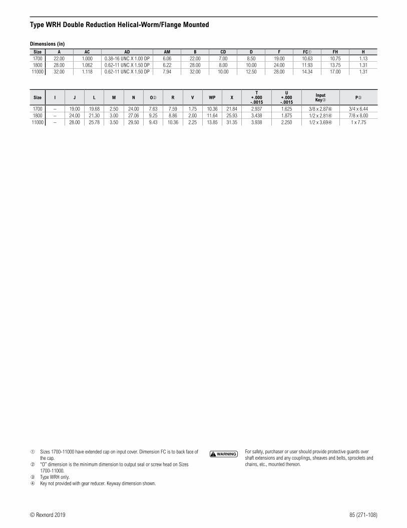
© Rexnord 2019 85 (271-108)
Type WRH Double Reduction Helical-Worm/Flange Mounted
Dimensions (in)
Size A AC AD AM B CD D F FC➀ FH H
1700 22.00 1.000 0.38-16 UNC X 1.00 DP 6.06 22.00 7.00 8.50 19.00 10.63 10.75 1.131800 28.00 1.062 0.62-11 UNC X 1.50 DP 6.22 28.00 8.00 10.00 24.00 11.93 13.75 1.31
11000 32.00 1.118 0.62-11 UNC X 1.50 DP 7.94 32.00 10.00 12.50 28.00 14.34 17.00 1.31
Size I J L M N O➁ R V WP XT
+.000 -.0015
U+.000 -.0015
Input Key➂ P➂
1700 – 19.00 19.68 2.50 24.00 7.63 7.59 1.75 10.36 21.84 2.937 1.625 3/8 x 2.87➃ 3/4 x 6.441800 – 24.00 21.30 3.00 27.06 9.25 8.86 2.00 11.64 25.93 3.438 1.875 1/2 x 2.81➃ 7/8 x 8.00
11000 – 28.00 25.78 3.50 29.50 9.43 10.36 2.25 13.85 31.35 3.938 2.250 1/2 x 3.69➃ 1 x 7.75
➀ Sizes 1700-11000 have extended cap on input cover. Dimension FC is to back face of the cap.
➁ “O” dimension is the minimum dimension to output seal or screw head on Sizes 1700-11000.
➂ Type WRH only.➃ Key not provided with gear reducer. Keyway dimension shown.
WARNING For safety, purchaser or user should provide protective guards over shaft extensions and any couplings, sheaves and belts, sprockets and chains, etc., mounted thereon.

86 (271-108) © Rexnord 2019
Helical and Worm PrimariesType WP Selection Guide
• Increases inventory & application flexibility.
• Choice of ratios 2:1 through 60:1.
• Three input types:
Solid input
Motorized hollow input
Motorized solid input/coupling
• Motor frame
WPM
Ratio Multipliers for Universal Mounting Between Any C-Face Motor & Drive
C-FaceInput
Standard NEMAC-Face Motor
Type HPHelical Primary
C-Face Mounted Input/Output
C-FaceOutput
Type WPWorm Primary
Worm Gear DriveReducer —Combined Ratiosto 216,000:1
Helical DriveReducer —Combined Ratiosto 60,000:1
Helical ShaftMounted Drive —Combined Ratiosto 1,500:1
C-FaceInput
Standard NEMAC-Face Motor
Type HPHelical Primary
C-Face Mounted Input/Output
C-FaceOutput
Type WPWorm Primary
Worm Gear DriveReducer —Combined Ratiosto 216,000:1
Helical DriveReducer —Combined Ratiosto 60,000:1
Helical ShaftMounted Drive —Combined Ratiosto 1,500:1
Helical and Worm Primaries

© Rexnord 2019 87 (271-108)
Helical and Worm PrimariesType WP Selection Guide
Selection Procedure
1. Determine Service Factor (SF).
2. Determine motor horsepower (HP), input RPM, output RPM & overall ratio.
Overall Ratio = Input RPM
Output RPM
3. Calculate equivalent output torque rating.
HP x SF x 6300
Output RPM
4. Select secondary size and type.
Input RPM = Motor RPM
Primary Ratio
Secondary Ratio = Overall Ratio
Primary Ratio
Select the secondary size and ratio at the corresponding input/output rpm with an output torque rating that exceeds the equivalent output torque.
5. Check overhung or thrust loads.
6. Select the primary size and type.
Select the primary size and ratio at the corresponding input/output rpm with an equivalent hp rating (SF x motor HP) that exceeds the drive input hp rating.
Match the primary C-face output to the secondary C-face input flange.
NOTE: The output torque delivered is a function of the overall drive combined efficiency!
7. Check drive dimensions.
Example:
Select a drive for a uniformly-loaded, hollow shaft connected belt conveyor with a headshaft speed of 17.5 rpm, operating 16 hours per day, driven by a 1750 rpm, 3 hp electric motor.
1. Service Factor is 1.25 from page 8.
2. Motor horsepower is 3 hp.
3. Drive output speed is 17.5 rpm,
1750 RPM Input
1750 RPM Output = 100:1 Overall Ratio
NOTE: When using a worm gear secondary, the selection can be made from the WBW Worm-Worm Quick Selection tables. After making the selection, substitute the WPM worm primary of the same size and ratio for the WBW standard primary, onto the secondary drive with a C-face input sized to match the primary output.
4. Equivalent output torque rating:
3 HP x 1.25 SF x 63,000
17.5 RPM = 3,500 lb-in
5. Select secondary size and type.
100:1 Overall Ratio
Primary Ratio = Secondary Ratio
1750 RPM
5:1 Primary Ratio = 350 RPM Secondary Input Speed
Select the secondary size at 350 rpm input with 20:1 ratio and an output torque rating equal to or greater than 13,500 lb-in.
6. No overhung or thrust loads.
7. Select primary size and type:
Equivalent HP rating = 3 HP x 1.25 SF = 3.75 Ehp.
Select the primary size at 1750 rpm input and 20:1 ratio with an input hp rating greater than 3.75 hp.
8. Check drive dimensions.
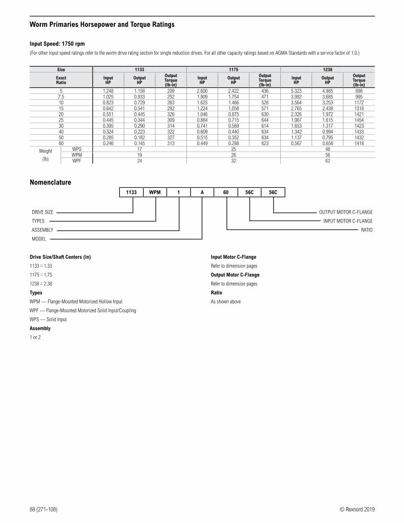
88 (271-108) © Rexnord 2019
Worm Primaries Horsepower and Torque Ratings
Input Speed: 1750 rpm
(For other input speed ratings refer to the worm drive rating section for single reduction drives. For all other capacity ratings based on AGMA Standards with a service factor of 1.0.)
Size 1133 1175 1238
ExactRatio
InputHP
OutputHP
OutputTorque(lb-in)
InputHP
OutputHP
OutputTorque(lb-in)
InputHP
OutputHP
OutputTorque(lb-in)
5 1.248 1.158 209 2.600 2.422 436 5.323 4.985 8987.5 1.025 0.933 252 1.909 1.754 471 3.992 3.685 99510 0.823 0.729 263 1.625 1.466 528 3.564 3.253 117215 0.642 0.541 292 1.224 1.058 571 2.765 2.438 131820 0.551 0.445 326 1.046 0.875 630 2.326 1.972 142125 0.445 0.344 309 0.884 0.715 644 1.967 1.615 145430 0.395 0.290 314 0.741 0.569 614 1.653 1.317 142340 0.324 0.223 322 0.609 0.440 634 1.342 0.994 143350 0.285 0.182 327 0.515 0.352 634 1.137 0.795 143260 0.246 0.145 313 0.449 0.288 623 0.567 0.656 1418
Weight
(lb)
WPS 17 25 48WPM 19 26 56WPF 24 32 62
Nomenclature1133 WPM 1 A 60 56C 56C
DRIVE SIZE
TYPES
ASSEMBLY
MODEL
OUTPUT MOTOR C-FLANGE
INPUT MOTOR C-FLANGE
RATIO
Drive Size/Shaft Centers (in)
1133 = 1.33
1175 = 1.75
1238 = 2.38
Types
WPM — Flange-Mounted Motorized Hollow Input
WPF — Flange-Mounted Motorized Solid Input/Coupling
WPS — Solid Input
Assembly
1 or 2
Input Motor C-Flange
Refer to dimension pages
Output Motor C-Flange
Refer to dimension pages
Ratio
As shown above

© Rexnord 2019 89 (271-108)
ILMR
NX
CD
D A DIA.
B DIA.
U
TAP, (4) EQ. SP.ON J BOLT CIRCLE
CT
ILMR
NX
CD
D A DIA.
B DIA.
U
TAP, (4) EQ. SP.ON J BOLT CIRCLE
CT
Type WPM, WPS Worm Primaries
Motor Data
NEMA Motor Flange Face Locations (in)
Drive Size56C/140TC 180TC 210TC
LA LC LB LD LD1133 3.46 6.07 – – –1175 4.09 6.70 – – –1238 4.63 7.76 5.06 8.76 8.76
NEMA Motor Mounting Dimensions (in)
Frame Size AJ AK BA BB BD BF BG UA Keyway
56C 5.88 4.50 0.38 – 5.88 0.41 6.64 0.625 0.1875 x 0.0938140TC 5.88 4.50 0.38 – 5.88 0.41 6.64 0.875 0.1875 x 0.0938180TC 7.25 8.50 – 0.50 9.00 0.53 – 1.125 0.2500 x 0.1250210TC 7.25 8.50 – 0.50 9.00 0.53 – 1.375 0.3125 x 0.1562
Dimensions (in)
SeriesOutput C-Face Frame
A B C D CD I J L M N R X Tap SizeT
+.000 -.0015
U +.000 -.0015
Input Key➁ Output Key
1133 56C 4.50 6.64 4.66 1.72 1.33 2.61 5.88 3.82 1.76 5.00 2.06 1.84 3/8-16 UNC 0.625 0.500 1/8 X 1.00 3/16 X 1.501175 140TC 4.50 6.64 5.44 2.06 1.75 3.24 5.88 4.45 1.76 4.28 2.13 1.81 3/8-16 UNC 0.875 0.625 3/16 X 1.38 3/16 X 1.381238 180TC 8.50 9.00 6.88 2.69 2.38 3.77 7.25 5.51 2.38 6.59 2.37 1.97 1/2-13 UNC 1.125 0.750 3/16 X 1.63 1/4 X 1.75
Motor Mounting Dimensions
NEMA Dimensions (in)
SizeLM L1 LQ
48CZ/ 56C/140TC
LQ1 RQ
48CZ 56C/ 140TC
180TC/ 210TC 250TC 180TC 210TC 250TC 48CZ/
56C/140TC 180TC 210TC 250TC
1133 5.63 6.07 – – 3.46 – – – 3.09 – – –1175 6.26 6.70 – – 4.09 – – – 3.59 – – –1238 – 7.76 8.76 – 4.63➂ 5.06 – – 4.09➂ 4.56 – –
IEC B5 & B3/B5 Metric Dimensions (in)➄
SizeLQ1 RQ
D63D D71D D80D D90D D100LD/D112MD D132D D63D D71D D80D D90D D100LD/
D112MD D132D
1133 2.62 2.65 2.89 – – – 2.45 2.47 2.71 – – –1175 3.25 3.28 3.52 – – – 2.95 2.97 3.21 – – –1238 – 3.72 4.34 – – – – 3.46 3.71 – – –
Type
WPS
CD
LQLQ1
RQ
A DIA.N
R
BD
AJAK
X
BF(4) HOLES
(2) HOLES3/8-16
T
B DIA.
I
D
TAP, (4) EQ. SP.ON J BOLT CIRCLE
BE1BE
C
Type
WPM
➀ Reverse all arrows for opposite input shaft rotation. Contact Rexnord for other mountings or assembly positions.
NEMA Dimensions (in)
Frame AJ AK BD BE BE1 Bore Dia. Keyway➃ BF
48CZ 3.75 3.00 4.36 0.38 – 0.500 1/8 x 1/16 0.2856C 5.88 4.50 6.50 0.38 – 0.625 3/16 x 3/32 0.41
140TC 5.88 4.50 6.50 0.38 – 0.875 3/16 x 3/32 0.41180TC 7.25 8.50 9.00 – 0.50 1.125 1/4 x 1/8 0.53210TC 7.25 8.50 9.00 – 0.50 1.375 5/16 x 5/32 0.53
Frame AJ AK BD BE Bore Dia. Keyway➃ BF TAP OD
D63D 115 95 117 10 11 4 x 2 M8 x 1.25 131D71D 130 110 132 11 14 5 x 2.5 M8 x 1.25 146D80D 165 130 165 15 19 6 x 3 M10 x 1.50 184
IEC B5 & B3/B5 Metric Dimensions (mm)
➁ Type WPS only.➂ 48CZ not available.➃ Keyway width by depth.➄ Metric IEC B5 input flange options are available only on quill input styles.
WARNING For safety, purchaser or user should provide protective guards over shaft extensions and any couplings, sheaves and belts, sprockets and chains, etc., mounted thereon.
Type
WPF
U
LDLC
BABB
L
HIGH-SPEEDSHAFT KEY
Type
WPF
Assemblies ➀
R
L2
1
Assemblies ➀
R
L
1R
L2
Dimensions and Assemblies

90 (271-108) © Rexnord 2019
Additional Product Offerings for Special Applications
Stainless Steel BISSC Certified
• Suitable for harsh environments and special wash-down applications.
• Housings and covers are 304 grade cast stainless steel, output shafts are 303 grade stainless steel.
• External hardware is all stainless steel.
• Includes Pressure Equalizing System.
• Viton® seals are standards.
• Synthetic lube.
• Stainless steel nameplate.
• Suitable for wash-down applications and furnished with USDA approved paint, 303 stainless steel output shafts, Viton seals, smooth exterior surfaces, solid head plugs and bolts for easy cleaning and a stainless steel nameplate.
Certifications:
• Baking Industry Sanitation Standard Committee (BISSC) Certified
• Standard Lubrications us USDA H-2 Approved
Size and Type Availability of Stainless Steel and BISSC Certified
DriveSize
Single Reduction Double ReductionWBF WBM WBQM WBWF WBWM WBWQM
56/140 56/140 180/210 56/140 180/210 56/140 56/140 56/1401133 X X X X X X1154 X X X X X X
1175 ➀ X X X X X X1206 X X X* X X* X X X1238 X X X* X X* X X X
1262 ➀ X X X* X X* X X X1325 X X X* X X* X X X
➀ Stainless steel only. * Only available with 180 frame.
Additional Products Available
• Ratios larger than 100:1
• Double reduction worm reducers
• Size 1425-1800
Accessories and Additional Information

© Rexnord 2019 91 (271-108)
Accessories
Horizontal Output Foot Kit (HOFK)
Vertical Output Foot Kit (VOFK)
Vertical Input Foot Kit (VIFK)
Oil Level Sight Gauge (OLSG)
Riser Block (RB)
Drive Size Number1133 HOFK 11331154 HOFK 11541175 HOFK 11751206 HOFK 12061238 HOFK 12381262 HOFK 12621300 HOFK 13001325 HOFK 13251425 HOFK 14251525 HOFK 15251600 HOFK 16001700 HOFK 17001800 HOFK 1800
11000 HOFK 11000
Drive Size Number1133 VOFK 11331154 VOFK 11541175 VOFK 11751206 VOFK 12061238 VOFK 12381262 VOFK 12621300 VOFK 13001325 VOFK 13251425 VOFK 14251525 VOFK 15251600 VOFK 16001700 VOFK 17001800 VOFK 180011000 VOFK 11000
Drive Size Number1133 VIFK 11331154 VIFK 11541175 VIFK 11751206 VIFK 12061238 VIFK 12381262 VIFK 12621300 VIFK 13001325 VIFK 13251425 VIFK 14251525 VIFK 1525
Drive Size Number1133 OLSG 11331154 OLSG 11541175 OLSG 11751206 OLSG 12061238 OLSG 12381262 OLSG 12621300 OLSG 13001325 OLSG 13251425 OLSG 14251525 OLSG 15251600 OLSG 16001700 OLSG 17001800 OLSG 1800
11000 OLSG 11000
Drive Size Number Height (inches)
1133 – –1154 RB 1154 2.001175 RB 1175 2.001206 RB 1206 2.001238 RB 1238 2.001262 RB 1262 1.501300 RB 1300 2.131325 RB 1325 2.131425 RB 1425 2.131525 RB 1525 1.251600 – –1700 – –1800 – –
11000 – –
Tie Rod (TRK) Hollow Output Flange Kit (OFK)
Drive Size Number1133 TRK 11331154 TRK 11541175 TRK 11751206 TRK 12061238 TRK 12381262 TRK 12621300 TRK 13001325 TRK 13251425 TRK 14251525 TRK 15251600 TRK 1600
Drive Size Number1133 OFK 11331154 OFK 11541175 OFK 11751206 OFK 12061238 OFK 12381262 OFK 12621300 OFK 13001325 OFK 13251425 OFK 14251525 OFK 15251600 OFK 16001700 OFK 1700 ➀1800 OFK 1800 ➀11000 OFK 11000 ➀
NOTE: Flange can only mount to “bolted cover side” of hollow reducer on sizes 1133-1525. Please specify correct mounting assembly with order. Refer to dimension pages for assembly positions.
Motor Flange & Coupling (MFK)
Drive Size Number Drive Size Number
1133MFK 1133-48
1325
MFK 1325-56MFK 1133-56 MFK 1325-140
MFK 1133-140 MFK 1325-180
1154MFK 1154-48 MFK 1325-210MFK 1154-56
1425
MFK 1425-56MFK 1154-140 MFK 1425-140
1175MFK 1175-48 MFK 1425-180MFK 1175-56 MFK 1425-210
MFK 1175-140 MFK 1425-250
1206MFK 1206-48
1525
MFK 1525-56MFK 1206-56 MFK 1525-140
MFK 1206-140 MFK 1525-180
1238
MFK 1238-56 MFK 1525-210MFK 1238-140 MFK 1525-250MFK 1238-180
1600MFK 1600-180
MFK 1238-210 MFK 1600-210
1262
MFK 1262-56 MFK 1600-250MFK 1262-140
1700MFK 1700-180
MFK 1262-180 MFK 1700-210MFK 1262-210 MFK 1700-250
1300
MFK 1300-56 1800 MFK 1800-210MFK 1300-140 MFK 1800-250MFK 1300-180MFK 1300-180

92 (271-108) © Rexnord 2019
Technical Information — Bolt Circle Dimensions
NOTE: Reducers do not have tapped holes on “integral cover side” of reducer. Integral side of reducer can be machined with tapped holes. See reverse housing assembly below for dimensions.
BOLT SIZE
BOLT SIZE
BOLT SIZE BOLT SIZE
A
A
B
B
EF
CD
CD
E
F
Size 1133 Size 1154-1206 Size 1238-11000
Output Cover Dimensions (in)Drive Size A B Bolt Size
1133 1.016 2.033 0.312-181154 1.016 2.033 0.312-181175 1.480 2.961 0.312-181206 1.480 2.961 0.312-181238 1.856 3.712 0.312-181262 1.856 3.712 0.312-181300 2.298 4.596 0.375-161325 2.298 4.596 0.375-161425 2.939 5.877 0.438-141525 3.359 6.717 0.438-141600 Consult Factory 0.500-131700 Consult Factory 0.500-131800 Consult Factory 0.500-13
11000 Consult Factory 0.500-13
Input Cover Dimensions (in)Drive Size C D E F Bolt Size
1133 1.219 2.438 – – 0.312-181154 1.219 2.438 – – 0.312-181175 1.219 2.438 – – 0.312-181206 1.219 2.438 – – 0.312-181238 1.313 2.625 0.781 1.562 0.312-181262 1.313 2.625 0.781 1.562 0.312-181300 1.600 3.200 1.050 2.100 0.438-141325 1.600 3.200 1.050 2.100 0.438-141425 1.600 3.200 1.050 2.100 0.438-141525 1.600 3.200 1.050 2.100 0.438-141600 1.370 2.740 1.370 2.740 0.438-141700 2.033 4.066 2.033 4.066 0.438-141800 2.121 4.242 2.121 4.066 0.500-13
11000 Consult Factory 0.625-11

© Rexnord 2019 93 (271-108)
Double-Ended High-Speed Shafts
Dimension (in)
Solid/Solid Size 1133-1325
LA LM
U
M
HIGH-SPEEDSHAFT KEY
HIGH-SPEEDSHAFT KEY
Drive L LA M U Key1133 3.82 4.37 1.76 0.500 0.1250 x 1.441154 4.35 4.90 1.76 0.625 0.1875 x 1.501175 4.45 5.00 1.76 0.625 0.1875 x 1.501206 4.82 5.37 1.76 0.625 0.1875 x 1.501238 5.51 6.15 2.38 0.750 0.1875 x 1.501262 6.07 6.72 2.38 0.750 0.1875 x 1.501300 6.57 7.22 2.38 0.875 0.1875 x 1.501325 6.76 7.40 2.38 0.875 0.1875 x 1.50
Solid/Solid Size 1425-1525
LA LM
U
M
HIGH-SPEEDSHAFT KEY
HIGH-SPEEDSHAFT KEY Z
Drive L M U Key1425 9.57 3.47 1.250 0.2500 x 2.881525 10.88 3.38 1.250 0.2500 x 3.00
Solid/Solid Size 1600-11000
LA LM
U
M
HIGH-SPEEDSHAFT KEY
HIGH-SPEEDSHAFT KEY
Drive L LA M MA U Key Z1600 11.78 14.55 3.41 3.41 1.500 0.3750 x 3.00 0.331700 11.50 13.88 2.97 2.51 1.625 0.3750 x 2.81 0.351800 12.50 15.50 2.84 2.98 1.875 0.5000 x 2.81 0.5711000 15.50 18.82 3.76 4.13 2.250 0.5000 x 3.69 0.51
Quill/Solid Size 1133-1600
L
REFER TO STANDARDMOTOR DATA
U
M
HIGH-SPEEDSHAFT KEY
Drive L M U Key1133 4.37 1.76 0.500 0.1250 x 1.441154 4.90 1.76 0.625 0.1875 x 1.501175 5.00 1.76 0.625 0.1875 x 1.501206 5.37 1.76 0.625 0.1875 x 1.501238 6.15 2.38 0.750 0.1875 x 1.501262 6.72 2.38 0.750 0.1875 x 1.501300 7.22 2.38 0.875 0.1875 x 1.501325 7.40 2.38 0.875 0.1875 x 1.501425 9.55 3.47 1.250 0.2500 x 2.881525 10.88 3.39 1.250 0.2500 x 3.00
1600 ➀ 14.55 3.41 1.500 0.3750 x 3.00
➀ Size 1600 comes standard with fan not shown.

94 (271-108) © Rexnord 2019
Non-Preferred Mounting Positions
The mounting positions noted below are not recommended due to the increased probability of leakage from high-speed shafts seals. Assembly position options also apply to motor flange drives.
Single Reduction
All types of worm drives mounted in the Worm-Under position or where the drive is rotated so the high-speed solid shaft is pointing vertically down.
Double Reduction/Worm-Worm
All types of worm primaries where the primary is in the Worm-Under position or where the worm primary is rotated so the high-speed shaft is pointing vertically down.
Double Reduction/Helical-Worm
All types of helical primaries where the high-speed shaft is in the six o’clock position (high-speed shaft is beneath the low-speed shaft ) or where the helical primary is positioned with the high-speed shaft pointing vertically down.

© Rexnord 2019 95 (271-108)
Technical Information — Oil Capacities and Lubrication
The precision-made gears and bearings in Falk Omnibox Worm Gear Drives require high-grade lubricants of the proper viscosity to maintain trouble-free performance. Synthetic lubricants provide the potential for numerous benefits including wider operating temperature range and increased interval between changes. For normal ambient temperatures (-10°F to 105°F)➀ we recommend the use of ISO viscosity grade Mobile Glygoyle 460 polyalkalene glycol (PAG) lubricant which is the standard oil shipped in our product and is compatible with the Viton seal material used through Size 1525. For other temperatures, contact Rexnord for a recommendation. For synthetic lubrication to be used in helical reducers (primaries of helical-worm reducers and ratio multipliers), contact Rexnord.
➀ Temperature range for continuous duty. For intermittent duty, contact Rexnord.
Oil Capacities (oz) - Standard Units
Mounting PositionUnit Size
1133 1154 1175 1206 1238 1262 1300 1325 1425 1525 1600 1700➁ 1800➁ 11000➁Worm Over 4 12 12 20 24 40 56 72 112 188 312 560 768 1152
Worm Under 8 16 20 28 40 60 84 108 152 304 328 524 820 1280Vertical Output 4 16 16 28 32 48 68 88 128 248 320 332 460 640Vertical Input 4 16 16 24 32 48 72 92 128 248 325 584 800 1200
Extended Bearing – – – – – – – 8 12 17 27 640 1008 1632Worm Over on
Secondary of Double Reduction
– – – – – – – 192 308 320 485 805 1144 1716
Stainless Steel and Washguard® All
Mounting Positions6 14 18 26 32 50 78 98 – – – – – –
➁ Shipped dry.
CAUTION Always check for proper oil level after filling. Capacities vary somewhat with model and mounting position. Oil should rise to bottom edge of level hole. Do not overfill.
CAUTION Do not operate the reducer without making sure it contains the correct amount of oil. Do not overfill or underfill with oil, or injury to personnel, or damage to reducer or other equipment may result.
Standard Gear Reducer Mounting Positions & Vent Plug, Level and Drain Locations➂
LEVEL
DRAIN
VENT
DRAIN
LEVEL
VENT
DRAIN
LEVEL
VENT
DRAIN
LEVEL
VENT
DRAIN
VENT
LEVELLEVEL
VENT
DRAIN
DIPSTICKLEVEL
DRAIN
VENT
WORM OVER VERTICAL OUTPUT
WORM UNDER VERTICAL INPUT
EXTENDED BEARING
DOUBLE REDUCTION WORM-WORM
Lubrication
Units shipped from factory are assembled to properly lubricate all internal components based on a specific assumed mounting orientation. Factory-assumed mounting orientations are given below. If a Size 1175 or larger unit will be mounted in a different orientation than listed below or run with sustained input speeds less than 1200 rpm, it should be specified with the order. The unit can then be modified to assure proper lubrication.
Factory-Assumed Mounting Orientation Applicable Unit Types ➅
Worm Over WB, WO, WL, WBQ, WLQ Single ReductionWBW, WOW, WLW, WBWQ, WLWQ Double Reduction Worm-WormWBH, WOH, WBHQ, WLHQ Double Reduction Helical-Worm
Worm Under WU Single ReductionWUW Double Reduction Worm-Worm
Vertical Output WX, WR Single ReductionWXW, WRW Double Reduction Worm-WormWXH, WRH Double Reduction Helical-Worm
Vertical Input WJ Single ReductionWJW Double Reduction Worm-Worm
➅ Includes “F” and “M” versions of all styles listed.
16 oz = 1 pint
2 pints = 1 quart
4 quarts = 1 gallon
1 gallon = 128 oz = 231 in3
➂ Does not apply to Stainless Steel, Washguard or units with Enviroseal option. ➃ For 4-1/4 through 6 inch center distance units (far side plug).➄ For 7 inch center distance & larger units.NOTE: High oil levels apply to all 4-1/4 inch center distance & larger secondary & tertiary units, regardless of primary unit type.

96 (271-108) © Rexnord 2019
Falk Omnibox Interchangeability
Component Interchangeability of Gear Drives & Accessories 100W Series & 1000W Series ➀100W Series 100 133 154 175 206 238 262 300 325 425 525 600 700 800 10001000W Series NA 1133 1154 1175 1206 1238 1262 1300 1325 1425 1525 1600 1700 1800 11000
WB ➁ YES ➄ YESWBM ➄ ➂ YES NA
WBQ ➂ YES ➄ YESWBQM ➄ ➂ YES NA
HOFK ➂ YESVOFK ➂ YESVIFK ➂ YES NA
Tie Rod ➂ YES NASlide Base ➂ YES NA
Oil Sight Gauge ➂ YESWWAK ➂ NO NAMFK ➂ NO YES NA
Coupling for MFK ➂ YES NAOutput Flange ➂ NO YESRiser Blocks ➂ YES NA
Bushings ➂ YES ➃ YESFans ➂ NA NO YES
Scoop Mount ➂Top Motor Mount ➂
Drywell ➂Added 1000 Series Features
Pressure Equalizing System NA Refer to Product Catalog for Specific Feature Availability
Stainless Steel Drives NA Refer to Product Catalog for Specific Feature Availability
➀ NA = Not Available Yes = Item is interchangeable between 100 & 1000 Series Drives. No = Item is not interchangeable between 100 & 1000 Series Drives.➁ Item or size is discontinued for 1000 Series.➂ Distance from the end of the input shaft to the centerline of the drive is shorter on the 1000 Series Omnibox. All other critical dimensions are the same.➃ 100 Series Bushings may be used in 1000 Series Drives provided the setscrew holes are redrilled.➄ Sizes 1700 and 1800 are Types WBF or WBQF.

© Rexnord 2019 97 (271-108)
Overhung Load and Thrust Loads
Overhung Load — Overhung load is imposed upon a shaft when a pinion, sprocket, or sheave is used as a power take-off. The magnitude of the load varies with the type of take-off and its proximity to the shaft bearing. Calculate the load (including minimum required service factor) and check the result against the tabulated overhung load rating. The overhung load formula below considers the transmitted horsepower without service factor. This is appropriate for applications where starting loads, momentary overloads, and brake capacities do not exceed 200% of drive rating (100% overload). For other conditions, compute the equivalent power by multiplying the transmitted power by the appropriate service factor.
Overhung Load Formulas:
Output OHL = 126,000 x motor hp x output hp rating x Fc x Lf
pitch diameter x input hp rating x output rpm
Input OHL = 126,000 x motor hp x output hp rating x Fc x Lf
pitch diameter x input rpm
Where:
Output hp Rating = from pages 17-20
Input hp Rating = from pages 17-20 (Single Reduction), pages 45-49 (Double Reduction, Worm-Worm), or page 76 (Double Reduction, Helical-Worm)
Fc = load connection factor
Lf = load location factor (The input shaft OHL is assumed to be applied at one shaft diameter from the seal cage, (Lf = 1.0). If the load is applied at a distance greater than one shaft diameter from the seal cage, refer the application to Rexnord.)
The calculated overhung load must be less than or equal to the capacity shown on page 98.
Load Location Factor (Lf) — The output shaft load location factors are shown below.
Load Connection Factor (Fc)Type of Connection Factor
Sprocket or Timing Belt ➀ 1.00Machined Pinion & Gear ➀ 1.25
V-Belt 1.50Flat Belt 2.50
Synchronous (Timing) Belts ➀ 1.30
➀ Refer all multiple chain, sprocket and pinion-mounted applications to Rexnord for deflection analysis.
Locate the centerline of the load as close to the drive housing as practical to minimize the overhung load and increase the bearing life. The overhung load formula employs the transmitted horsepower, without service factor, providing the overloads starting loads and brake capacities do not exceed the amounts listed in Basic Information on page 4.
Example:
Gear Drive Size = 1325WB2B30, exact ratio of 30.0
Input hp rating = 3.619 hp
Output hp rating = 2.986 hp
Motor = 3.0 hp at 1750 rpm
Low-speed shaft rpm =
4-inch diameter sprocket mounted on low-speed shaft. Centerline of sprocket overhung load is positioned at 1.125 inches.
Calculate the overhung load as follows:
OHL = 126,000 x 3.0 x 2.986 x 1.00 x 0.95
= 1270 lb4 x 58.3 x 3.619
Allowable OHL on page 98 is 2275 lbs and is satisfactory for this selection.
Lf - Load Location Factors for Output ShaftsDistancein inches
➁
Drive Size
1133 1154 1175 1206 1238 1262 1300 1325 1425 1525 1600 1700 1800 11000
0.250 0.89 0.890.375 0.93 0.930.500 0.96 0.96 0.92 0.90 – 0.890.625 1.00 1.00 0.94 0.93 0.90 0.910.750 1.08 1.08 0.97 0.95 0.91 0.93 0.92 0.89 0.860.875 1.16 1.16 1.00 0.97 0.94 0.95 0.94 0.91 0.88 0.881.000 1.23 1.23 1.06 1.00 0.97 0.98 0.96 0.93 0.91 0.89 0.88 0.69 0.68 0.631.125 1.31 1.31 1.13 1.07 1.00 1.00 0.98 0.95 0.92 0.91 0.89 0.72 0.71 0.651.250 1.39 1.39 1.20 1.14 1.03 1.03 1.00 0.98 0.93 0.92 0.90 0.75 0.74 0.671.375 1.48 1.48 1.28 1.21 1.09 1.08 1.06 1.00 0.94 0.93 0.92 0.76 0.76 0.691.500 1.56 1.56 1.35 1.27 1.14 1.12 1.10 1.03 0.96 0.94 0.93 0.79 0.77 0.711.625 1.64 1.64 1.42 1.33 1.21 1.16 1.16 1.06 0.97 0.96 0.94 0.81 0.79 0.721.750 1.72 1.72 1.49 1.39 1.28 1.22 1.21 1.10 0.98 0.97 0.95 0.82 0.80 0.731.875 1.79 1.82 1.56 1.45 1.35 1.27 1.26 1.12 1.00 0.99 0.96 0.84 0.82 0.752.000 – – – 1.52 1.45 1.33 1.31 1.16 1.04 1.00 0.97 0.87 0.84 0.772.250 – – – – 1.64 1.47 1.42 1.25 1.11 1.06 1.00 0.91 0.88 0.802.500 – – – – – 1.64 1.52 1.33 1.18 1.12 1.09 0.96 0.92 0.842.750 – – – – – – 1.62 1.45 1.25 1.19 1.18 1.00 0.96 0.873.000 – – – – – – 1.72 1.59 1.33 1.25 1.27 1.04 1.00 0.903.250 – – – – – – 1.83 1.72 1.41 1.32 1.35 1.08 1.04 0.933.500 – – – – – – – – 1.47 1.39 1.43 1.13 1.08 0.973.750 – – – – – – – – 1.54 1.45 1.52 1.18 1.12 1.004.000 – – – – – – – – – 1.52 1.61 1.23 1.16 1.034.250 – – – – – – – – – – 1.69 1.28 4.20 1.064.500 – – – – – – – – – – 1.79 1.32 1.24 1.104.750 – – – – – – – – – – 1.89 1.36 1.28 1.135.000 – – – – – – – – – – 1.96 1.40 1.32 1.165.750 – – – – – – – – – – – – – 1.26
➁ Distance is in inches from the L.S. Seal Cage. Interpolate for Load Location Factors at intermediate distances. For example, the load location factor is 1.56 for Size 1262 when distance is 2.375 inches. Consult Rexnord for distances greater than those shown.
DISTANCE
CENTER LINEOF LOAD
HOUSING

98 (271-108) © Rexnord 2019
Overhung Load and Thrust Loads
Consult Factory for Higher Overhung Load Ratings — In many cases, overhung load capacity in excess of that published is available. Published ratings are based on a combination of the most unfavorable conditions of rotation, speed, direction of applied load and drive loading. If the actual load should exceed the published capacity, refer full details to Factory.
Thrust LoadsOutput shaft external thrust capacities are shown below. The applied external thrust must be less than or equal to the published capacity. The published thrust capacity is for applications with a pure thrust load only. Combined overhung load and thrust applications should be referred to the Factory.
Engineering Data
The following overhung load values are based on load located at one shaft diameter from seal cage. Published ratings are based on a combination of the most unfavorable conditions of loading. For higher ratings, refer full data to Factory.
Single Reduction L.S. Shaft Overhung Load (lb)
NominalRatio
Speed (RPM) Drive Size
Input Approx.Output 1133 1154 1175 1206 1238 1262 1300 1325 1425 1525 1600 1700 1800 11000
5
1750 350
700 860 1200 494 1770 1625 2170 2275
2204 2384 3538
6209 7761 110281170 234 2265 2591 37231700 174 2265 2750 3723100 20 2265 2752 3723
7.5
1750 233
700 860 1200 494 1770 1625 2170 2275 2265
2724
3723 6209 7761 110281170 156 27521700 116 2752100 13 2752
All Other Ratios 700 860 1200 494 1770 1625 2170 2275 2265 2752 3723 6209 7761 11028
Single Reduction H.S. Shaft Overhung Load (lb)Drive Size 1133 1154 1175 1206 1238 1262 1300 1325 1425 1525 1600 1700 1800 11000
H.S. Shaft OHL 75 75 75 75 125 125 150 150 175 300 450 450 450 500
Single Reduction L.S. Shaft Thrust Load Capacity (lb)
Nominal Ratio
Drive Size1133 1154 1175 1206 1238 1262 1300 1325 1425 1525 1600 1700 1800 11000
5 827 794 793 735 1451 1420 1729 1605 1445 1675 3633 4009 4777 68087.5 948 949 868 811 1659 1609 1944 1869 1640 2021 3990 4009 4777 680810 1070 1056 976 898 1820 1762 2147 2026 1788 2449 3990 4009 4777 680815 1144 1144 1144 1099 2091 2069 2459 2490 2319 3033 3990 4009 4777 6808
All Other Ratios 1144 1144 1144 1144 2091 2091 2574 2574 2533 3412 3990 4009 4777 6808
Double Reduction (Worm-Worm) L.S. Shaft & H.S. Shaft Overhung Load & Thrust Load Capacity (lb)Drive Size 1133 1154 1175 1206 1238 1262 1300 1325 1425 1525 1600 1700 1800 11000
L.S. Shaft OHL (all ratios) 419 517 473 494 1107 1107 1518 1536 2265 2752 3951 6209 7761 11028
H.S. Shaft OHL (all ratios) 75 75 75 75 75 75 75 75 75 125 150 150 175 300
L.S. Shaft Thrust 1144 1144 1144 1144 2091 2091 2574 2574 2533 3412 3990 4009 4777 6808
Double Reduction & Triple (Helical-Worm) Overhung Load & Thrust Load Capacity (lb)Drive Size 1700 1800 11000
L.S. Shaft OHL 6209 7761 11028H.S. Shaft OHL 175 300 450
L.S. Shaft Thrust 4009 477 6808

© Rexnord 2019 99 (271-108)
Overhead Conveyor Drive — WRExtended Output Shaft Drive Overhung Load
Single and Double Reduction Input Shaft Overhung Load (lb)Drive Size 1133 1154 1175 1206 1237 1262 1300 1325 1425 1525 1600 1700 1800 11000
Single Reduction 75 75 75 75 125 125 150 150 175 300 450 450 450 500Double Reduction
Worm-Worm 75 75 75 75 75 75 75 75 75 125 150 150 175 300
Double Reduction Helical-Worm 75 75 75 75 75 75 75 75 150 150 150 175 300 450
Single and Double Reduction Output Shaft Overhung Load (lb)Drive Size 1300 1325 1425 1525 1600 1700 1800 11000
OHL 605 959 1200 2524 2245 3791 4850 8500
Lf — Load Location Factors for Output ShaftsDistance fromEnd of Shaft
(in) ➀
Drive Size
1425 1525 1600 1700 1800 11000
0 1.00 1.00 1.00 1.00 1.00 1.000.5 1.03 1.03 1.02 1.02 1.02 1.021.0 1.06 1.06 1.04 1.04 1.04 1.031.5 1.09 1.09 1.06 1.06 1.05 1.052.0 1.12 1.12 1.09 1.08 1.07 1.062.5 1.16 1.15 1.11 1.10 1.09 1.083.0 1.20 1.19 1.14 1.13 1.11 1.103.5 1.24 1.23 1.16 1.15 1.13 1.124.0 1.28 1.27 1.19 1.17 1.15 1.144.5 1.32 1.32 1.22 1.20 1.18 1.165.0 1.37 1.36 1.25 1.23 1.20 1.185.5 1.43 1.42 1.28 1.26 1.23 1.206.0 – – 1.31 1.29 1.25 1.226.5 – – 1.35 1.32 1.28 1.247.0 – – 1.39 1.35 1.31 1.277.5 – – 1.42 1.38 1.33 1.298.0 – – – – 1.36 1.318.5 – – – – 1.40 1.349.0 – – – – 1.43 1.37
➀ Distance is in inches from the end of output shaft (inward towards housing). Interpolate for load location factors at intermediate distances. For example, the load location factor is 1.21 for Size 1525 when distance is 3.25 inches.
Consult Factory for Higher Input Shaft Overhung Ratings
In many cases, overhung load capacity in excess of that published is available. Published ratings are based on a combination of the most unfavorable conditions of rotation, speed, direction of applied load and drive loading. If the actual load should exceed the published capacity, refer full details to the Factory.
Input Shaft OHL
Calculate the input shaft overhung load using the following formula:
Input OHL = 126,000 x motor HP x Fc x Lf
pitch diameter x input RPM
Where:
Fc = load connection factor (below)
Lf = load location factor — the input shaft OHL is assumed to be applied at one shaft diameter from the seal cage, (Lf = 1.0). If the calculated overhung load exceeds the capacity shown above or if the load is applied at a distance greater than one shaft diameter from the seal cage, refer the application to the Factory.
Load Connection Factor (Fc)Type of Connection Factor
Sprocket or Timing Belt 1.00Machined Pinion & Gear ➁ 1.25
V-Belt 1.50Flat-Belt 2.00
Synchronous (Timing) Belts 1.30
➁ Refer all multiple chain, sprocket and pinion-mounted applications to Factory for deflection analysis.

Why Choose Rexnord?When it comes to providing highly engineered products that improve productivity and efficiency for industrial applications worldwide, Rexnord is the most reliable in the industry. Commitment to customer satisfaction and superior value extend across every business function.
Delivering Lowest Total Cost of OwnershipThe highest quality products are designed to help prevent equipment downtime and increase productivity and dependable operation.
Valuable ExpertiseAn extensive product offering is accompanied by global sales specialists, customer service and maintenance support teams, available anytime.
Solutions to Enhance Ease of Doing BusinessCommitment to operational excellence ensures the right products at the right place at the right time.
866-REXNORD/866-739-6673 (Within the U.S.)414-643-2366 (Outside the U.S.)
www.rexnord.com
©2019 Rexnord 271-108 06/19