fanno.pdf
TRANSCRIPT

CHAPTER 8
Fanno Flow
Adiabatic flow with friction name after Ginno Fanno a Jewish engineer is the secondmodel described here. The main restriction for this model is that heat transfer isnegligible and can be ignored 1. This model is applicable to flow processes whichare very fast compared to heat transfer mechanisms, small Eckert number. which are considerably
slower (see more discus-sion about dimensionlessnumber in the chapterabout dimensional analysis(not included yet.).
This model explains many industrial flow processes which includes emptyingof pressured container through relatively a short tube, exhaust system internalcombustion engine, compressed air systems, etc. As this model raised from needto explain the steam flow in turbines.
8.1 Introduction
Consider a gas flows through a conduit with a friction (see Figure 8.1). It isadvantages to examine the simplest situation and yet without losing the coreproperties of the process. Later, more general case will be examined2.
1Even the friction does not converted into heat2Not ready yet, discussed on the ideal gas model and on the ideal gas model and the entry length
issues.
125

126 CHAPTER 8. FANNO FLOW
�� ��� ��� �
� � � � ���
c.v.
flowdirection
�� � ���� � � ��� ��� � � � �
���
�!No heat transer
Figure 8.1: Control volume of the gas flow in a constant cross section
8.2 Model
The mass (continuity equation) balance can be written as"#%$'&)(+*,$.-0/21436587)195 (8.1): ; &=<>*?<@$'&)A0*BAThe energy conservation (under the assumption of this model as adiabatic flow
and the friction in not transformed into thermal energy) readsCED < $ C9D A (8.2): ; C <�F *?< AG -IH $ C AJF *BA AG -8H(8.3)
Or in a derivative form K H2L C FMLON * AGQP $'R (8.4)

8.2. MODEL 127
Again for simplicity, the perfect gas model is assumed3.
� $'&�� C (8.5): ; � <&=< C < $ � A&)A C AIt is assumed that the flow can be approximated as one dimensional. The force
acting on the gas is the friction at the wall and the momentum conservation reads
� ( L � ����� L ( � $ "# L=* (8.6)
It is convenient to define a hydraulic diameter as
� $ � �Cross Section Area
wetted perimeter(8.7)
Or in other words (.$�� �A
� (8.8)
It is convenient to substitute�
for of��
but it is referred to the same hydraulicdiameter. The infinitesimal area that shear stress is acting on isL)( � $ � � L�� (8.9)
Introducing the Fanning friction factor as a dimensionless friction factor whichsome times referred to as friction coefficient and reads as following:
� $ ���<A &=* A (8.10)
Utilizing equation (8.2) and substituting equation (8.10) into momentum equation(8.6) yields
�
�� ��� �� �A
� L � � � � L�� ���� ��� �� N��G &=* A P $.( ! "
�#���#�&=* L=* (8.11)
3The equation of state is written again here so that all the relevant equations can be found whenthis chapter is printed separately.
128 CHAPTER 8. FANNO FLOW
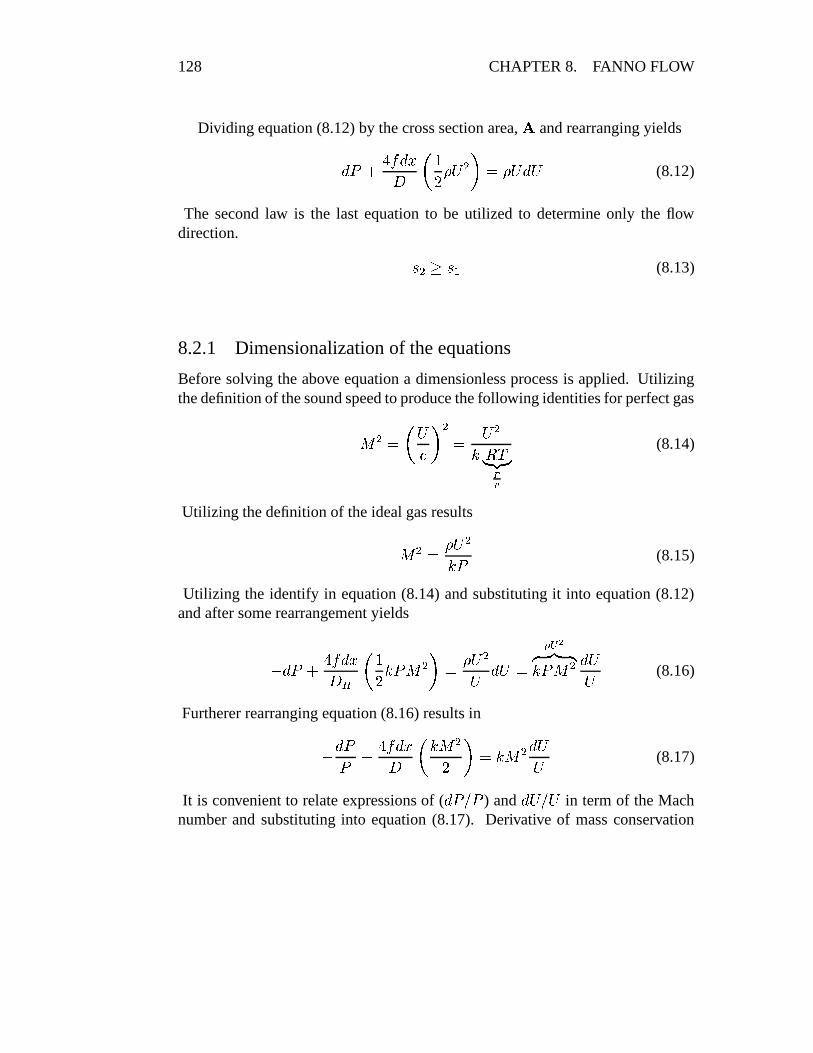
Dividing equation (8.12) by the cross section area, � and rearranging yields
� L � F � � L��� N��G &=* A P $.&=* L=* (8.12)
The second law is the last equation to be utilized to determine only the flowdirection. 3 A��.3 < (8.13)
8.2.1 Dimensionalization of the equations
Before solving the above equation a dimensionless process is applied. Utilizingthe definition of the sound speed to produce the following identities for perfect gas
� A $ N * - P A $ * A� � C�#���#�� � (8.14)
Utilizing the definition of the ideal gas results
� A $ &=* A� � (8.15)
Utilizing the identify in equation (8.14) and substituting it into equation (8.12)and after some rearrangement yields
� L � F � � L �� N �G � ��� A P $ &=* A* L=*'$ ���� ��� �� ��� A L=** (8.16)
Furtherer rearranging equation (8.16) results in
� L �� �� � L��� N � � AG P $ � � A L=** (8.17)
It is convenient to relate expressions of ( L �� � ) and L=* * in term of the Machnumber and substituting into equation (8.17). Derivative of mass conservation
8.2. MODEL 129
(8.2) results
L && F����� ��� �
�G L * A* A $,R (8.18)
The derivation of the equation of state (8.6) and dividing the results by equationof state (8.6) results L �
� $ L)&& F L CL C (8.19)
Derivation of the Mach identity equation (8.14) and dividing by equation (8.14)yields L�� � A��
� A $ L�� * A��* A � L CC (8.20)
Dividing the energy equation (8.4) by
K H and utilizing definition Mach numberyields L CC F �N � �
� � � �� P
� ��� ���
�C * A* A L N * AG P $: ; L CC F � � � �
�� � C� ��� � �
* A* A L N * AG P $: ; L CC F � � �G � A L * A* A $'R (8.21)
Equations (8.17), (8.18), (8.19), (8.20), and (8.21) need to be solved. These This equation is obtainedby combining the definitionof Mach number with equa-tion of state and mass con-servation. Thus, the origi-nal limitations must be ap-plied to the resulting equa-tion.
equations are separable so one variable is a function of only single variable (thechosen independent variable). Explicit explanation is provided only two variables,rest can be done in similar fashion. The dimensionless friction, ���� � , is chosen asindependent variable since the change in the dimensionless resistance, ���� � , causesthe change in the other variables.
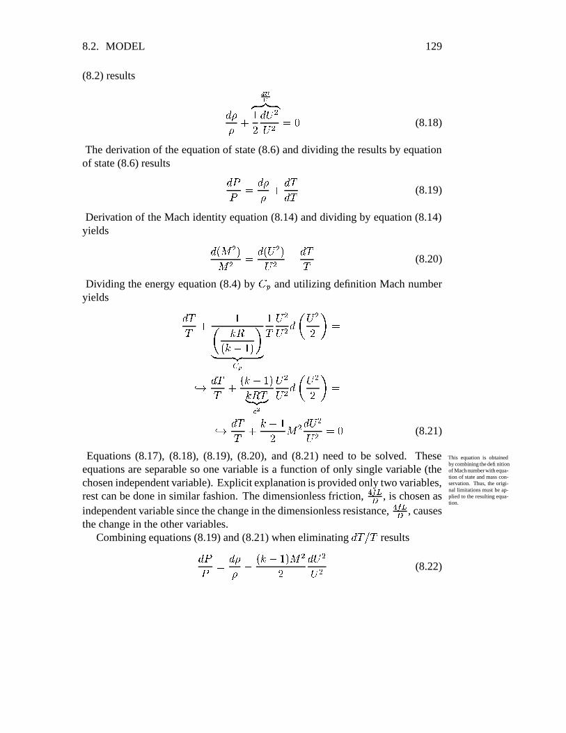
Combining equations (8.19) and (8.21) when eliminating L C �C resultsL �� $ L && � � � � �
� � AG L=* A* A (8.22)

130 CHAPTER 8. FANNO FLOW
The term ��� can be eliminated utilizing equation (8.18) and substituting into
equation (8.22) and rearrangement yieldsL �� $ � � F � � � �
� � AG L=* A* A (8.23)
The term L=* A * A can be eliminated by using (8.23)L �� $ �
� � A � � F � � � �� � A �G � � � � A � � � L��
� (8.24)
The second equation for Mach number,�
variable is obtained by combiningequation (8.20) and (8.21) by eliminating L C �C . Then L)& & and * are eliminatedby utilizing equation (8.18) and equation (8.22). and only left is
�. Then L �� �
can be eliminated by utilizing equation (8.24) and results in� � L��� $ � � � � A � L � A
� � � � � F���� <A � A � (8.25)
Rearranging equation (8.25) results inL � A� A $ � � A�� � F ��� <A � A�
� � � A � � L �� (8.26)
After similar mathematical manipulation one can get the relationship for thevelocity to read L=** $ � � AG � � � � A � � � L �� (8.27)
and the relationship for the temperature isL CC $ �G L -- $ �� � � � �
� � �G � � � � A � � � L��� (8.28)
density is obtained by utilizing equations (8.27) and (8.18) to obtainL)&& $ �� � AG � � � � A � � � L��� (8.29)
The stagnation pressure similarly obtained asL � D�BD $ �
� � AG � � L��� (8.30)

8.3. THE MECHANICS AND WHY THE FLOW IS CHOCK? 131
The second law reads L 3 $ K H���� L CC � �����L �� (8.31)
The stagnation temperature expresses asC4D $ C � � F � � � � � G � A �
. Takingderivative of this expression when
�is remains constant yields L C�D $ L C � � F� � � � � G � A �
and thus when these equations are divided they yieldsL C 2C $'L C9D �C9D (8.32)
In the similar fashion the relationship between the stagnation pressure and thepressure and substitute in the entropy equation resultsL 3 $ K H���� L CEDCED � �����
L �BD� D (8.33)
The first law requires that the stagnation temperature remains constant, � L C�D $.R � .Therefore the entropy change L 3K H $ � � � � �
��
L � D� D (8.34)
Utilizing the equation for stagnation pressure the entropy equation yieldsL 3K H $ � � � �� � AG � � L��
� (8.35)
8.3 The Mechanics and Why The Flow is Chock?
The trends of the properties can examined though looking in equations (8.24)through (8.34). For example, from equation (8.24) it can be observed that thecritical point is when
� $ � . When� � � the pressure decreases downstream
as can seen from equation (8.24) because� L�� and
�are positive. For the same
reasons, in the supersonic branch,� � � , the pressure increases downstream. This
pressure increase is what makes compressible flow so different than “conventional”flow. Thus the discussion will be divided into two cases; one of flow with speedabove speed of sound, and, two flow with speed below of speed of sound.
132 CHAPTER 8. FANNO FLOW
Why the flow is chock?
There explanation is based on the equations developed earlier and there is no knownexplanation that is based on the physics. First it has to recognized that the criticalpoint is when
� $ � at which show change in the trend and singular by itself.For example, L � ��� � $ �
� $�� and mathematically it is a singular point (seeequation (8.24)). Observing from equation (8.24) that increase or decrease fromsubsonic just below one
� $ � � ����
to above just above one� $ � � F � � requires
a change in a sign pressure direction. However, the pressure has to be a monotonicfunction which means that flow cannot crosses over the point of
� $ � . Thisconstrain means that because the flow cannot “cross–over”
� $ � the gas has toreach to this speed,
� $ � at the last point. This situation called chocked flow.
The Trends
The trends or whether the variables are increasing or decreasing can be observedfrom looking at the equation developed. For example, the pressure can be examinedby looking at equation (8.26). It demonstrates that the Mach number increasesdownstream when the flow is subsonic. On the other hand, when the flow issupersonic, the pressure decreases.
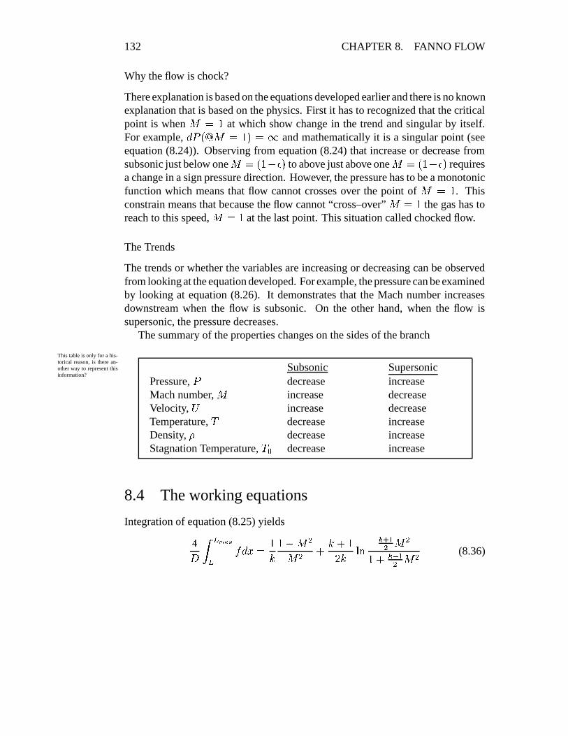
The summary of the properties changes on the sides of the branch
This table is only for a his-torical reason, is there an-other way to represent thisinformation?
Subsonic SupersonicPressure,
�decrease increase
Mach number,�
increase decreaseVelocity, * increase decreaseTemperature,
Cdecrease increase
Density, & decrease increaseStagnation Temperature,
CEDdecrease increase
8.4 The working equations
Integration of equation (8.25) yields��� !��
� L��O$ �� � �� A
� A F � F �G � ������ <A � A
� F ��� <A � A (8.36)

8.4. THE WORKING EQUATIONS 133
A representative friction factor is defined as
�� $ ��������� !��D � L�� (8.37)
Utilizing the mean average theorem equation (8.36) yields
� �� ������� $ �� � �
� A� A F � F �G � ���
��� <A � A� F ��� <A � A (8.38)
It common to replace the��
with�
which is adopted in this book.Equations (8.24), (8.27), (8.28), (8.29), (8.29), and (8.30) can be solved. For
example, the pressure as written in equation 8.23 is represented by ���� � , and Machnumber. Now equation 8.24 can eliminate term ���� � and describe the pressure onthe Mach number. Dividing equation 8.24 in equation 8.26 yields
�
�� �� �
$ � � F � � � � �AG � A � � F ��� <A � A � L � A (8.39)
The symbol “*” denotes the state when the flow is choked and Mach number isequal to 1. Thus,
� $ � when� $ � �
Equation (8.39) can be integrated to yield:
�� � $ ��
��� <A� F ��� <A � A (8.40)
In the same fashion the variables ratio can be obtainedCC � $ - A- � A $ ��� <A� F ��� <A � A (8.41)
&& � $ �� � F ��� <A � A� � <A (8.42)
** � $ N && � P � < $ � ��� <A� F ��� <A � A (8.43)

134 CHAPTER 8. FANNO FLOW
The stagnation pressure decreases can be expressed by
� D� D � $
� < ����� �� � � � �� ����#���#��BD� �� D �� ��#���#�
� ���� � � �� ���� � (8.44)
Utilizing the pressure ratio in equation (8.40) and substituting into equation (8.44)yields
� D� D � $ �
� F ��� <A � A��� <A �� ��� �� � F ��� <A � A
��� <A (8.45)
And further rearranging equation (8.45) provides
� D� D � $ ��
�� F ��� <A � A
��� <A �� ���� � � ���(8.46)
The integration of equation (8.34) yields3 � 3 �-8H $ ��� � A����� � � F �G � A � � F ��� <A � A � ��� ��(8.47)
The results of these equations are plotted in figure 8.2 The fanno flow is in manydiscussion about Reynoldsnumber and dimensionlessfriction ������ parameter. cases shockless and therefore a relationship between two points should be derived.
In most of the times, the “star” values are imaginary values that represent the valueat choking. The real ratio can be obtained by ratio of two star ratios as an exampleC AC < $ ������� � ��� ���� � � (8.48)
A special interest is the equation for the dimensionless friction as following� � �
� � �� L �O$ � !��
�� � �� L�� � � !��
�� � �� L�� (8.49)
Hence, N � � ������� P A $ N � � ������� P < � � � �� (8.50)

8.4. THE WORKING EQUATIONS 135
0.1 1 10Mach number
0.01
0.1
1
1e+01
1e+024fL
D
PP
*
T0/T
0
*
P0/P
0
*
U/U*
Fanno FlowP/P
*, ρ/ρ*
and T/T* as a function of M
Fri Sep 24 13:42:37 2004
Figure 8.2: Various parameters in Fanno flow as a function of Mach number
8.4.1 Example
Example 8.1:Air flows from a reservoir and enters a uniform pipe with a diameter of 0.05 [m]and length of 10 [m]. The air exits to the atmosphere. The following conditionsprevail at the exit:
� A $ ����� 7���� temperatureC A $ G��� � A $ R� �� 4. Assume that
the average friction factor to be� $,R� R R � and that the flow from the reservoir up
to the pipe inlet is essentially isentropic. Estimate the total temperature and totalpressure in the reservoir under the Fanno flow model.
SolutionFor isentropic flow to the pipe inlet, temperature and total pressure at the pipeinlet are the same as the those in the reservoir. Thus, finding the total pressure andtemperature at the pipe inlet is the solution. With the Mach number and temperature
4This property is given only for academic purposes. There is no Mach meter.

136 CHAPTER 8. FANNO FLOW
������� ��� � �������������������
� �"!$#&% ')(�*,+-/."021,3,4�5
687�9;:�< =>8?$@)ACB D E
Figure 8.3: Schematic of example 1
known at the exit, the total temperature at the entrance can be obtained by knowingthe ���� � . For given Mach number (
� $,R� �� ) the following is obtained.
F G&HJIK LL � L"ML"M � �� � NN � OO �R� � R R R R R� R � �QP � � � G � � � R RSR � � R��T � R� � � �/U � R�T G �So the total temperature at the exitC �WV A $ C �C ���� A
C A $ T R R� RST G � $ G � R� P �YX �
To "move" the other side of the tube the ���� � is added as
���� � �� < $ ��� � F ��� � �� A $� � R� R R �� � RR� R P F R� R � �QP �[Z T� G �
The rest of the parameters can be obtained with the new ��� � either from the tableby interpolations or utilizing attached program.
F G&HJIK LL � L"ML"M � �� � NN � OO �R� \T P R�R U T� G � R R T� R � � R � � � R P G P � U � R� \T�R�R � � � � U � �5
Note that the subsonic branch is chosen. the stagnation ratios has to be addedfor
� $,R� \T P R�R UF OO M
�� M]]_^ LL"M
]a` L] � ` L"MR� bT P � R� �� � P R ���TSR � � � R R� � � P � P � G5whatInfo = infoStandard ;
variableName = fldV;k = 1.4;FLD = 3.21 ;

8.4. THE WORKING EQUATIONS 137
The total pressure�BD < can be found from the combination of the ratios as follows:
� D < $ �� ��� � �� ��� �
� A � �� ���� A�� � ���� <
� D� ���� <$ � � �
� � G � � T � T� R � �� �R� � � P $ G �� ����� 7����
C9D <?$ � �� ��� �� �� ��� �C A C �C ���� ACC � ���� <
C9DC ���� <$ T R R � �� R�T G � � � � � � �R� � � P Z T � R X $ � P �
Another academic question:
������� ���� �������������� ���� �! �"�#$&%�')(+*�*,
-/.�0�1�2 3 46587�9 :�; <�=shock
d-c nozzle
>@?BABC
atmosphereconditions
Figure 8.4: The schematic of Example 2
Example 8.2:A system compromised from a convergent-divergent nozzle followed by a tubewith length of 2.5 [cm] in diameter and 1.0 [m] long. The system is supplied by avessel. The vessel conditions are is at 29.65 [Bar], 400 K. With these conditionsa pipe inlet Mach number is 3.0. A normal shock wave occurs in the tube and theflow discharges to the atmosphere, determine;

138 CHAPTER 8. FANNO FLOW
(a) the mass flow rate through the system;
(b) the temperature at the pipe exit; and
(c) determine the Mach number that a normal shock wave occurs [� �
].
Take k = 1.4, R = 287 ��� ��� X � and� $.R� R R P .
Solution
(a) Assuming that the pressure vessel very much larger than the pipe therefore,the velocity in the vessel can be assumed small enough so it can be neglected.Thus, the stagnation conditions can be approximated as the condition in thetank. It further assumed that the flow through the nozzle can be approximatedas isentropic. Hence,
C D <@$ � R R X and� D < $ G �� U�P � � 7�� �
The mass flow rate through the system is constant and for simplicity reasonpoint 1 is chosen in which, "#%$.&)( � -The density and speed of sound are unknowns and needed to be computed.
With the isentropic relationship the Mach number at point one is known thefollowing can be found either from table or program6
F OO M�� M
]] ^ LL"M]a` L] � ` L"MT� R R R R R� \T P � � � R� R � U G T � G T ��U R� R G � G G R� � � P G R
The temperature is C <@$ C <CED < CED < $,R� \T P � � � R R+$ � � G \R XWith the temperature the speed of sound can be calculated as- < $�� � � C $ � � � � G R � � � � G bR Z G T �� P � � # 3�� -��
6It should pay attention that in the program the variable whatInfo = infoStagnation ; and notwhatInfo = infoStandard ;

8.4. THE WORKING EQUATIONS 139
The pressure at point 1 can be calculated as
� < $ � <�BD < � D < $,R� R G� � T R Z R� bR ����� 7����
The density as a function of other properties at point 1 is&=< $ �� C ���� < $
R� � � � R �G R � � � � G bR Z � � ��� ���#����The mass flow rate can be evaluated from equation (8.2)"#%$ � � � � � � R� R G P A� � T � G T �� P � $,R� U � � ���3�� -��
(b) First, a check weather the flow is shockless by comparing the flow resistanceand the maximum possible resistance. From the table or by using the attachedprogram7, obtain the flowing
F G HJIK LL � L ML"M � �� � NN � OO �T� R R R R R� P G G � U R� G � R G G � G T ��U R� P R� � R � �� U � R R� � G R P �and the conditions of the tube are
��� � $ � � R� R R P� � RR� R G P $'R� bRSince R� \R � R� P G G � U the flow is chocked and with a shock wave.
The exit pressure determines the location of the shock, if a shock exists, bycomparing “possible”
��� ���to��
. Two possibilities needed to be checked; one,the shock at the entrance of the tube, and two, shock at the exit and comparingthe pressure ratios. First, possibility of the shock wave occurs immediately atthe entrance for which the ratio for
� �are (shock wave table)
7

140 CHAPTER 8. FANNO FLOW
F�� F�
O��O�� � �� � L �L � L"M �L M �T� R R R R R� � � P � � G U � � R T� \R P � � � R� \T�T�T�T R� bT G R�T �After shock wave the flow is subsonic with “
� < ” $,R� � � P � � . (fanno flow table)
F G&HJIK LL � L ML M � �� � NN � OO �R� � � P � � � G � � � G G P � � � bT � R � � �� U � R R� P R � � � � � � R �The stagnation values for
� $,R� � � P � � are
F OO M�� M
]] ^ LL"M]a` L] � ` L"MR� � � P � � R� � PSU � � R� bR� P �QP � \T � R � R� \R PSU � U � � � � G
The ratio of exit pressure to the chamber total pressure is
� A�BD $ <
� ��� �N � A� � P N � �� < P N � <�BD � P N �BD �� D � P <� ��� �N � D ��BD P$ � � �G G P � � � R� \R PSU R � R� bT G R�T �� �$,R� � G � � U
The actual pressure ratio � G �� U/P $'R� R�T�T�R is smaller than the case in whichshock occurs at the entrance. Thus, the shock is somewhere downstream. Onepossible way to find the exit temperature,
C A is by finding the location of theshock. To find the location of the shock ratio of the pressure ratio,
� � is needed.With the location of shock, “claiming” up stream from the exit through shock tothe entrance. For example, calculating the parameters for shock location withknown ���� � in the “y” side. Then either utilizing shock table or the program toobtained the upstream Mach number.
The procedure of the calculations:
1) Calculated the entrance Mach number assuming the shock occurs at theexit:
a) set���A $ � assume the flow in the entire tube is supersonic:

8.5. SUPERSONIC FLOW 141
b) calculated���<
Note this Mach number is the high Value.
2) Calculated the entrance Mach assuming shock at the entrance.
a) set� A $ �
b) add ���� � and calculated� < ’ for subsonic branch
c) calculated� �
for� < ’
Note this Mach number is the low Value.
3) according your root finding algorithm8 calculated or guess the shock location To check Secant Method.
and then compute as above the new� < .
a) set� A $ �
b) for the new ���� � and compute the new�� ’ as on the subsonic branch
c) calculated� �
’ for the�� ’
d) Add the leftover of ��� � and calculated the� <
4) guess new location for the shock according to your finding root procedureand according the result repeat previous stage until finding the solution.
F�� F�� G&HJIK �� ��� G&HJIK �� ����� F�� F�
T� R R R R � R R R R R� G G R � � R� P � ��R � � ��R �� R� P � � � R(c) The way that numerical procedure of solving this problem is by finding ���� � �� Hthat will produce
� <?$ T . In the process� �
and�� must be calculated (see
the chapter on the program with its algorithms.).
8.5 Supersonic Flow
In chapter 7 it was shown that the isothermal model cannot describe the adequatelythe situation because the thermal entry length is relatively large compared to thepipe length and the heat transfer is not sufficient to maintain constant temperature.In the Fanno model there is no heat transfer, and, furthermore, the because the verylimited amount of heat transformed it closer to a adiabatic flow. The only limitation
8You can use any method you which, but be-careful second order methods like Newton-Rapsonmethod can be unstable.

142 CHAPTER 8. FANNO FLOW
of the model is uniform of the velocity (assuming parabolic flow for laminar anddifferent profile for turbulent flow.). The information from the wall to the tubecenter9 is slower in reality. However, experiments by many starting with 1938work by Frossel10 since has shown that the error is not significant. Nevertheless,the comparison with shows that heat transfer cause changes to the flow and theyneeded to be expected. This changes includes the choking point at lower Machnumber.To insert example on the
change in the flow rate be-tween isothermal flow toFanno Flow. Insert also ex-ample on percentage of heattransfer.
on the comparison ofthe maximum length ofisothermal model andFanno Model.
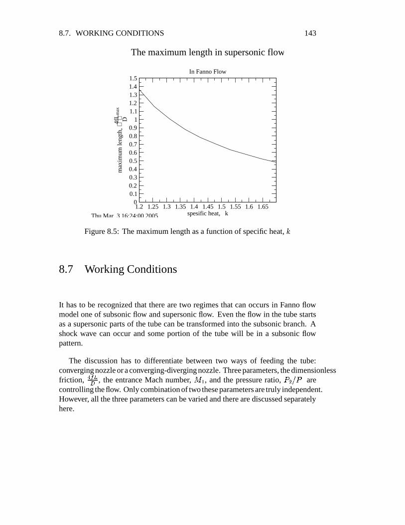
8.6 Maximum length for the supersonic flow
It has to be noted and recognized that as oppose to subsonic branch the supersonicbranch has a limited length. It also must be recognized that there is a maximumlength for which only supersonic flow can exist11. These results were obtainedfrom the mathematical derivations but were verified by numerous experiments12.The maximum length of the supersonic can be evaluated when
� $ � as follow:
� � ��� ���� $ � � � A
� � A F � F �G � ������ <A � AG � � F ��� <A � A � $
���� � � � ; � ��
� �� � � F � F �G � ���� � F �
� �� � � �
� �$ � �� F � F �G � ���� � F �
�G � � � ��$ ���� � � � ; �
�
� $ � �� $'R� \R G � P
The maximum length of the supersonic flow is limited by the above number. Fromthe above analysis, it can be observed that no matter how high the entrance Machnumber will be the tube length is limited and depends only on specific heat ratio,�
as shown in figure 8.5.
9The word information referred into the shear stress transformed from the wall to centerer ofthe tube.
10See on the web http://naca.larc.nasa.gov/digidoc/report/tm/44/NACA-TM-844.PDF11Many in the industry have difficulties to understand this concept. This author seeking nice
explanation of this concept for the non–fluid mechanics engineers. This solicitation is about howto explain this issue to non-engineers or engineer without proper background.
12If you have experiments demonstrating this point, please provide to the undersign so they canbe added to this book. Many of the pictures in the literature carry copyright problems.
8.7. WORKING CONDITIONS 143
1.2 1.25 1.3 1.35 1.4 1.45 1.5 1.55 1.6 1.65spesific heat, k
00.10.20.30.40.50.60.70.80.9
11.11.21.31.41.5
max
imum
leng
th,
4f
Lm
ax
D
The maximum length in supersonic flow
In Fanno Flow
Thu Mar 3 16:24:00 2005
Figure 8.5: The maximum length as a function of specific heat,�
8.7 Working Conditions
It has to be recognized that there are two regimes that can occurs in Fanno flowmodel one of subsonic flow and supersonic flow. Even the flow in the tube startsas a supersonic parts of the tube can be transformed into the subsonic branch. Ashock wave can occur and some portion of the tube will be in a subsonic flowpattern.
The discussion has to differentiate between two ways of feeding the tube:converging nozzle or a converging-diverging nozzle. Three parameters, the dimensionlessfriction, ���� � , the entrance Mach number,
� < , and the pressure ratio,� A � < are
controlling the flow. Only combination of two these parameters are truly independent.However, all the three parameters can be varied and there are discussed separatelyhere.
144 CHAPTER 8. FANNO FLOW
����
�
����� ����� ����������������� �!#"$ %'&&&( )�*
+,,,-�.�/�0213 4'55567
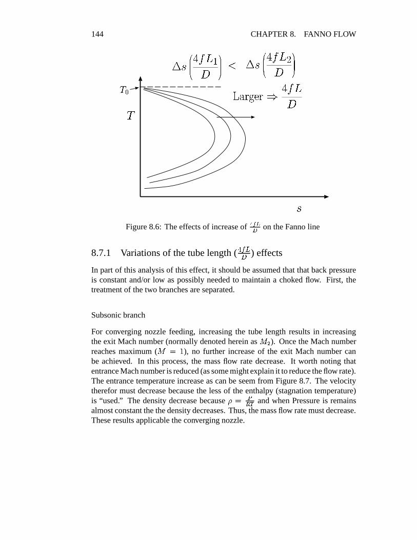
Figure 8.6: The effects of increase of ���� � on the Fanno line
8.7.1 Variations of the tube length ( 8:9�;< ) effects
In part of this analysis of this effect, it should be assumed that that back pressureis constant and/or low as possibly needed to maintain a choked flow. First, thetreatment of the two branches are separated.
Subsonic branch
For converging nozzle feeding, increasing the tube length results in increasingthe exit Mach number (normally denoted herein as
� A ). Once the Mach numberreaches maximum (
� $ � ), no further increase of the exit Mach number canbe achieved. In this process, the mass flow rate decrease. It worth noting thatentrance Mach number is reduced (as some might explain it to reduce the flow rate).The entrance temperature increase as can be seem from Figure 8.7. The velocitytherefor must decrease because the less of the enthalpy (stagnation temperature)is “used.” The density decrease because & $ = � and when Pressure is remainsalmost constant the the density decreases. Thus, the mass flow rate must decrease.These results applicable the converging nozzle.

8.7. WORKING CONDITIONS 145
���
�
�
constant pressurelines
Fanno lines
1
1’
1’’
2
2’
2’’
Figure 8.7: The development properties in of converging nozzle
In the case of the converging–diverging feeding nozzle, increase of the dimensionlessfriction, ���� � , results in a similar flow pattern as in the converging nozzle. Oncethe flow becomes choked a different flow pattern emerged.
Supersonic Branch
There are several transitional points that change the pattern on the flow. The point� is the choking point (for the supersonic branch) in which the exit Mach numberreaches to one. The point � is the maximum possible flow of supersonic flow notdepend on nozzle. The next point, referred here as the critical point, � , is the pointin which no supersonic flow is possible in the tube i.e. the shock reaches to thenozzle. There is another point, � , in which no supersonic flow is possible in theentire nozzle–tube system. Between these transitional points the effect parameterssuch and mass flow rate, entrance and exit Mach number are discussed.
At the starting point the flow is choked in the nozzle, (to achieve supersonicflow). The following ranges that has to be discussed which include (see figure 8.8):

146 CHAPTER 8. FANNO FLOW
0� ���� � � �
���� ������ � ���� R ; �
����� �
����� � ��� � ���� � � �
���� ������ � � � � � ; ��
���� ������ ��� � � � ���� � � �
���� ������ � � � � � ; ��
���� ������ ��� � � � ���� � � � � ; �
� ���
��
������
all supersonicflow
mixed supersonicwith subsonicflow with a shockbetween
the nozzleis stillchoked
�� !#"%$'&#(
)+*
,.-
a
b c/
0+1
Figure 8.8: The Mach numbers at entrance and exit of tube and mass flow rate forFanno Flow as a function of the ���� �The 0- � range, the mass flow rate is constant because the flow is choked at thenozzle. The entrance Mach number,
� < is constant because it is a function of thenuzzle design only. The exit Mach number,
� A decreases (remember this flow ison the supersonic branch) and starts ( ���� � $ R ) as
� A $ � < . At end of the range� ,� A $ � . In the range of � � � the flow is all supersonic.In the next range � � � � The flow is double choked and make the adjustment for
the flow rate at different choking points by changing the shock location. The massflow rate continue to be constant. The entrance Mach continues to be constant andexit Mach number is constant.
The total maximum available for supersonic flow � � � ��2 , � ���� � � ���� , is onlytheoretical length in which the supersonic flow can occur if nozzle will be provided

8.7. WORKING CONDITIONS 147
with a larger Mach number (a change the nozzle area ratio which also reduces themass flow rate.). In the range � � � , is more practical point.
In semi supersonic flow � � � � (in which no supersonic is available in thetube but only the nozzle) the flow is still double chocked and the mass flow rateis constant. Notice that exit Mach number,
� A is still one. However, the entranceMach number,
� < , reduces with the increase of ���� � .It worth noticing that in the � � � � the mass flow rate nozzle entrance velocity,
and the exit velocity remains constant!13
In the last range � � � � the end is really the pressure limitation or the breakof the model and the isothermal model is more appropriate to describe the flow. Inthis range, the flow rate decreases since (
"#�� � < )14. Should the mathematicalderivations be inserted todemonstrate it?To summarize the above discussion the figures 8.8 exhibits the developed of� < , � A mass flow rate as a function of ���� � . Somewhat different then the subsonic
branch the the mass flow rate is constant even the flow in the tube is completelysubsonic. This situation is because the “double” choked condition in the nozzle.The exit Mach
� A is a continuous monotonic function that decreases with ���� � .The entrance Mach
� < is a non continuous function with a jump at point whenshock occurs at the entrance “moves” into the nozzle.
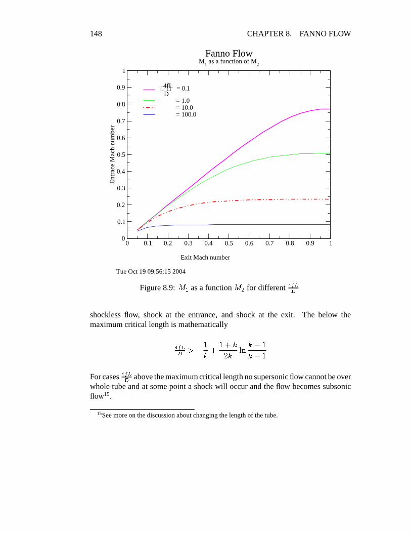
Figure 8.9 exhibits the� < as a function of
� A . The figure was calculated byutilizing the data from figure ?? by obtaining the ���� ! �� for
� A and subtractingthe given ���� � and finding the corresponding
� < .In the figure 8.10The figure 8.10 exhibits the entrance Mach number as a function of the
� A .Obviously there can be two extreme possibilities for the subsonic exit branch.Subsonic velocity occurs for supersonic entrance velocity, one, when the shockwave occurs at the tube exit and, two, at the tube entrance . In the figure 8.10only for ���� � $'R� � and ���� � $,R� � two extremes are shown. For ���� � $,R� G shownwith only shock at the exit only. Obviously, and as can be observed, the larger���� � creates larger differences between exit Mach number for the different shocklocation. The larger ���� � larger
� < must occurs even for shock at the entrance.
For a given ��� � , below the maximum critical length, the entrance supersonicentrance has three different regimes which depends on the back pressure. One,
13On personal note, this situation is rather strange to explain. On one hand, the resistanceincreases and on the other hand, the exit Mach number remains constant and equal to one. Isanyone have explanation for this strange behavior suitable for non–engineers or engineers withoutbackground in fluid mechanics.
14Note that ��� increases with decreases of ��� but this effect is less significant.
148 CHAPTER 8. FANNO FLOW
0 0.1 0.2 0.3 0.4 0.5 0.6 0.7 0.8 0.9 1
Exit Mach number
0
0.1
0.2
0.3
0.4
0.5
0.6
0.7
0.8
0.9
1
Ent
race
Mac
h nu
mbe
r
4fLD
= 0.1
= 1.0= 10.0= 100.0
Fanno FlowM
1 as a function of M
2
Tue Oct 19 09:56:15 2004
Figure 8.9:� < as a function
� A for different ���� �
shockless flow, shock at the entrance, and shock at the exit. The below themaximum critical length is mathematically
���� � � � �� F � F �G � ���� F �� � �
For cases ��� � above the maximum critical length no supersonic flow cannot be overwhole tube and at some point a shock will occur and the flow becomes subsonicflow15.
15See more on the discussion about changing the length of the tube.

8.7. WORKING CONDITIONS 149
0 0.2 0.4 0.6 0.8 1 1.2 1.4 1.6 1.8 2M
2
0
0.5
1
1.5
2
2.5
3
3.5
4
4.5
5M
1
4fLD
= 0.1
= 0.2 = 0.4 = 0.1 shock= 0.4
Fanno Flow
M1 as a function of M
2 for the subsonic brench
Tue Jan 4 11:26:19 2005
Figure 8.10:� < as a function
� A for different ���� � for supersonic entrance velocity
8.7.2 The Pressure Ratio,���� � , effects
In this section the studied parameter is the variation of the back pressure and thus,the pressure ratio
� � variations. For very low pressure ratio the flow can be assumedas incompressible while exit Mach number are smaller than
� R� \T . As the pressureratio increases (smaller back pressure,
� A ), the exit and entrance Mach numbersincrease. According to Fanno model the value of ���� � is constant (friction factor,�
, is independent of the parameters such as, Mach number, Reynolds number etc)thus the flow remains on the same Fanno line. For case where the supply comefrom a reservoir with a constant pressure, the entrance pressure decreases as wellbecause the increase in the entrance Mach number (velocity).

150 CHAPTER 8. FANNO FLOW
Again a differentiation of the feeding is important to point out. If the feedingnozzle is converging than the flow will be only subsonic. If the nozzle is “converging–diverging”than in some part supersonic flow is possible. At first the converging nozzle ispresented and later the converging-diverging nozzle is explained.
������ ��
���
������
critical Point ccriticalPoint bcritical Point a
a shock inthe nozzle
fully subsoinicflow
critical Point d
Figure 8.11: The pressure distribution as a function of ���� � for a short ���� �
Converging nozzle
Choking explanation for pressure variation/reduction
decreasing the pressure ratio or in actuality the back pressure, results in increase ofthe entrance and the exit velocity until a maximum is reached for the exit velocity.The maximum velocity is when exit Mach number equals one. The Much number,as it was shown in the chapter ??, can increase only if the area increase. In our modelthe tube area is postulated as a constant therefore the velocity cannot increase any

8.7. WORKING CONDITIONS 151
further. However, the flow to be continuous the pressure must decrease and for thatthe velocity must increase. Something must break since the conflicting demandsand it result in a “jump” in the flow. This jump and it is referred to as a chokedflow. Any additional reduction in the back pressure will not change the situationin the tube. The only change will be at tube surroundings which are irrelevant tothis discussion.
If the feeding nozzle is a “diverging-converging” then it is has to be differentiatedbetween two cases; One case is where the ���� � is short or equal to the criticallength. The critical length is the maximum ���� !�� � that associate with entranceMach number.
������ � �
���
������
critical Point ccriticalPoint bcritical Point a
a shock inthe nozzle
fully subsoinicflow� ��������� ����� ��� �!�"�#%$'&)(*+-,.�/0 1 23
46587:9 {;)<=>@?BA�CD E FG
H'IKJML HON�HQPSR-L T�L PUIWVYXZ[@\B]�^_ ` ab
Figure 8.12: The pressure distribution as a function of ��� � for a long ���� �

152 CHAPTER 8. FANNO FLOW
Short ���� �Figure 8.12 shows different of pressure profiles for different back pressures. beforethe flow reach critical point a (in the figure) the flow is subsonic. Up to this stage thenozzle feeds the tube increases the mass flow rate (with decreasing back pressure).Between point a and point b the shock is in the nozzle. In this range and furtherreduction of the pressure the mass flow rate is constant no matter how low theback pressure is reduced. Once the back pressure is less the point b the supersonicreaches to the tube. Note however that exit Mach number,
� A � � and is not 1.A back pressure that is at the critical point c results in a shock wave that is at theexit. When the back pressure is below point c, the tube is “clean” of any shock16.The back pressure below point c some a adjustment as to occurs with exceptionsof point d.
Long ���� �In the case of ���� � � ���� ! �� reduction of the back pressure results in the sameprocess as explain in the short ��� � up to to point c. However, point c in this case isdifferent from point c at the case of short tube ���� � � ���� !��� . In this point the exitMach number is equal to 1 and the flow is double shock. Further reduction of theback pressure at this stage will not “move” the shock wave downstream the nozzle.The point c or location of the shock wave is a function entrance Mach number,
� <and the “extra” ���� � . The is no analytical solution for the location of this point c.The procedure is (will be) presented in later stage.
8.7.3 Entrance Mach number, ��� , effects
In this discussion, the effect of changing the throat area on the nozzle efficiency areneglected. In reality these effects have significance and needed to be accounted forin some instances. This dissection deals only when the flow reaches the supersonicbranch reached otherwise the flow is subsonic with regular effects.. It is assumedthat in this discussion that the pressure ratio
� � is large enough to create a choked
flow and ���� � is small enough to allow it to happen.The entrance Mach number,
� < is a function of the ratio of the nozzle’s throatarea to the nozzle exit area and its efficiency. This effect is the third parameter
16It is common misconception that the back pressure has to be at point d.
8.7. WORKING CONDITIONS 153
0 0.05 0.1 0.15 0.2 0.25
4fLD
0
0.2
0.4
0.6
0.8
1
1.2
1.4
1.6
1.8
2M
ach
Num
ber
75% 50%5%
Mach number in Fanno Flow
4fLD
shock at
Tue Jan 4 12:11:20 2005
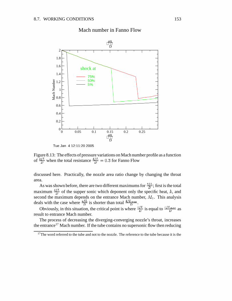
Figure 8.13: The effects of pressure variations on Mach number profile as a functionof ���� � when the total resistance ���� � $.R� \T for Fanno Flow
discussed here. Practically, the nozzle area ratio change by changing the throatarea.
As was shown before, there are two different maximums for ���� � ; first is the totalmaximum ���� � of the supper sonic which deponent only the specific heat,
�, and
second the maximum depends on the entrance Mach number,� < . This analysis
deals with the case where ���� � is shorter than total ���� !�� � .Obviously, in this situation, the critical point is where ���� � is equal to ��� !��� as
result to entrance Mach number.The process of decreasing the diverging-converging nozzle’s throat, increases
the entrance17 Mach number. If the tube contains no supersonic flow then reducing
17The word referred to the tube and not to the nozzle. The reference to the tube because it is the

154 CHAPTER 8. FANNO FLOW
0 0.05 0.1 0.15 0.2 0.25
4fLD
0
0.4
0.8
1.2
1.6
2
2.4
2.8
3.2
3.6
4
4.4
4.8
P2/P
1
5 %50 %75 %
P2/P1 Fanno Flow
4fLD
Fri Nov 12 04:07:34 2004
Figure 8.14: Fanno Flow Mach number as a function of ���� � when the total ���� � $R� \Tthe nozzle throat area wouldn’t increase the entrance Mach number.why? make a question,
is increase can increasethe possibility to super-sonic flow? This part is for the case where some part of the tube under supersonic regime
and there is shock as transition to subsonic branch. Decreasing the nozzle throatarea moves the shock location downstream. The “payment” for increase in thesupersonic length is by reducing the mass flow. Further, decrease of of the throatarea results in flashing the shock out the tube. By doing so, the throat area decreases.The mass flow rate is proportional linear to throat area and therefore the mass flowrate reduces. The process of decreases the throat area also results in increasing the
focus of the study.

8.7. WORKING CONDITIONS 155
� ���� ����� �������shock
��� ���
������
������� �! #"%$&(')*#+�,�-.
/102
354768
9999999 :<;>=?:@;�A<=
Figure 8.15: schematic of a “long” tube in supersonic branch
pressure drop of the nozzle (larger resistance in the nozzle18)19. Admittedly, this authorhave and can explain itmathematically. Theauthor did found anyphysical explanationdeveloped one. Perhapsit is challenge to publicas an open question ofhow to explain it. Thissimilar to surface tensionphenomenon that can beexplained only heavymathematics.
In the case of large tube ���� � � ���� !��� the exit Mach number increases withthe decrease of the throat area. Once the exit Mach number reaches one no furtherincreases is possible. However, the location of the shock wave approaches to thetheoretical location if entrance Mach,
� <?$ � .
The maximum location of the shock The main point in this discussion however,to find the furtherest shock location downstream. Figure 8.16 shows the possibleB �
���� ��
as function of retreat of the location of the shock wave from the maximumlocation. When the entrance Mach number is infinity,
� < $ � , if the shocklocation is at the Maximum length, than shock at
� � $ � results in�� $ � and
possibleThe proposed procedure is based on figure 8.16.
i) Calculated the extra ���� � and subtract the actual extra ���� � assuming shock atthe left side (at the max length).
ii) Calculated the extra ���� � and subtract the actual extra ���� � assuming shock atthe right side (at the entrance).
iii) According to the positive or negative utilizes your root finding procedure.
18Strange? frictionless nozzle has a larger resistance when the throat area decreases19It is one of the strange phenomenon that in one way increasing the resistance (changing the
throat area) decreases the flow rate while in a different way (increasing the C#DFEG ) does not affectthe flow rate.

156 CHAPTER 8. FANNO FLOW
������
������� �������
������������ ��
�����
!!!!!!! "$#&%0
')(+*-,
.0/+132
405+687
Figure 8.16: The extra tube length as a function of the shock location, ���� �supersonic branch
From numerical point of view, the Mach number equal infinity when left sideassume result in infinity length of possible extra (the whole flow in the tubeis subsonic). To overcame this numerical problem it is suggested to start thecalculation from � distance from the right hand side.
Let denote
B ����� �
� $ ����� � � � � � � ���� � H (8.51)
Note that ���� � H is smaller than ���� � �� � ���:9 . The requirement that has to satisfied
is that denote ���� � �� ; � � ; � � � as difference between the maximum possible of lengthin which the flow supersonic achieved and the actual length in which the flow issupersonic see figure 8.15. The retreating length is expressed as subsonic but
���� � �� ; � � ; � � �4$ ���� � �� � ���:9 � ���� � H (8.52)
As the figure ?? shows the entrance Mach number,� < is reduces after the
maximum length is excessed.

8.7. WORKING CONDITIONS 157
�����������
� ����� ����� �
����� ���
1
Figure 8.17: The maximum entrance Mach number,� < to the tube as a function
of ���� � supersonic branch
Example 8.3:Calculate the shock location for entrance Mach number
� < $ R and for ���� � $'R� �assume that
� $ � � .Solution
The solution is obtained by iterative process. The maximum ���� !�� � for� $ � �
is 0.821508116. Hence, ���� � exceed the the maximum length ���� � for this entranceMach number. The maximum for
� < $ R is ���� � $ R� � U R G R thus the extra tube,B ����� �
� $�R� � � R� � U R G R $�R� � T � R , At the left side is when the shock occurs at���� � $'R� � U R G R (flow chocked and no any additional ���� � ). Hence, the value of leftside is � R� � T � R . The right side is when the shock is at the entrance at which theextra ���� � is calculated for
� �and
�� is
F � F�
O �O � � �� � L �L � L"M �L"M �R� R R R R� bT� G � � T� � P PSU�P � � P R� R R�R � R�RWith � � < � 2
F G HJIK LL � L"ML"M � �� � NN � OO �R� bT � G � G � � G G � �/U � U � � G bT P � R� � G T � � � U �

158 CHAPTER 8. FANNO FLOW
The extraB �
���� ��
isG � � G � R� � T � R $ G bT � R G Now the solution is somewhere
between the negative of left side to the positive of the right side.20
The solution of the above utilizing results in the following table
F�� F � G HJIK �� ��� G&HJIK �� ����� F � F�
R� R R R � R R R R� P � R � R� bT G ��T � U � � R� U � R�T8.8 The Approximation of the Fanno flow by Isothermal
Flow
The isothermal flow model has equation that theoreticians are easier to use comparedto Fanno flow model.
One must noticed that the maximum temperature at the entrance isC�D < . When
the Mach number decreases the temperature approaches the stagnation temperature(C ; C9D
). Hence, if one allow certain deviation of temperature, say about 1%) thatflow can be assumed to be isothermal. This tolerance requires that � C�D � C � 2CED $R� � � which requires that enough for
� < � R� � P even for large� $ � U � . This
requirement provide that somewhere (depend) in the vicinity of ���� � $ G P the flowcan be assumed isothermal. Hence the mass flow rate is a function of ���� � because� < changes. Looking that the table or figure ?? or the results from computerprogram attached to this book shows that reduction of the mass flow is very rapid.to insert a question or ex-
ample about this issue inend As it can be seen for the figure 8.18 the dominating parameter is ���� � . The results
are very similar for isothermal flow. The only difference is in small dimensionlessfriction, ���� � .
8.9 More Examples
Example 8.4:To demonstrate the utility of the figure 8.18 consider the flowing example. Findthe mass flow rate for
� $ R� R P , � $ � � # � , � $ R� R G � # � and pressure ratio� A � < $�R� � �R� \T
�R� P
�R� bR . The stagnation conditions at the entrance are T R R X
and T ��� 7�� � air.
20What if the right side is also negative? The flow is choked and shock must occur in the nozzlebefore entering the tube. or in very long tube the whole flow will be subsonic.

8.9. MORE EXAMPLES 159
0 10 20 30 40 50 60 70 80 90 100
4fLD
0
0.1
0.2
0.3
0.4M
1P
2 / P
1 = 0.1 iso
P2 / P
1 = 0.8 iso
P2 / P
1 = 0.1
P2 / P
1 = 0.2
P2 / P
1 = 0.5
P2 / P
1 = 0.8
M1 Fanno flow
with comperison to Isothermal Flow
Wed Mar 9 11:38:27 2005
Figure 8.18: The entrance Mach number as a function of dimensionless resistanceand comparison with Isothermal Flow
SolutionFirst calculate the dimensionless resistance, ���� � .
���� � $ � � R� R P � �R� R G $ � RFrom Figure 8.18 for
� A � <@$'R� � � <�� R� � T etc.or accurately utilizing the program as in the following table.
F�� F � G&HJIK G&HJIK �� � G&HJIK �� � L��L��R� � G � G R � R R R R � R� R R R R � R� R R R R R� R R� ��� U T �R� � G � G R R� � R � � R � R� R R R R � G � U � � G � U � � R� bT R R R RR� ��� T � G R� G G U � � � R� R R R R P R� � PSU � � R� � PSU � R� P R R R RR� R � � � P R� R� � U/P � R� R R R R � R � � G U � � G R U R� bR R R R ROnly for the pressure ratio of 0.1 the flow is choked.

160 CHAPTER 8. FANNO FLOW
F OO M�� M
]] ^ LL M]a` L] � ` L MR� � G � G R R� � � U � � R� ��� � � P � P � � R R� ��R�R � � � P T ��TR� � G � G R R� � � U � G R� ��� G T�T � � R G� R� ��R � G R � U�P G TR� ��� T� G R� � � � � � R� ����T P � P ��� � U R� � � R � � P R � T�TR� R � � � P R� � ��R � T R� ��� U R�T � G R � G R� � � P�P U � G P � �
Therefore,C � CED
and for the same the pressure. Hence, the mass rate is afunction of the Mach number. The Mach number is indeed function of the pressureratio but and therefore mass flow rate is function pressure ratio only through Machnumber.
The mass flow rate is
"# $ � ( � � �� C $ T R R R R R � � � R� R G A� � R� � G� � �
� �G R � T R R � R� � R N ���3�� - Pand for the rest
"# N�� �� �
$,R� \T P � R� � R � R� � G � GR� � G � T $'R� �/U R N ���3�� - P"# N � �� �
$,R� P P � R� � R � R� ��� T �R� � G � T $,R� � T N ���3�� - P"# N�� �� �
$,R� bR P � R� � R � R� R � � � PR� � G� T $'R� \T R N ���3�� - P

8.9. MORE EXAMPLES 161
The table for Fanno Flow
Table 8.15: Fanno Flow Standard basic Table
F G&HJIK LL � L"ML"M � �� � NN � OO �R� R�T R R R � R � R�R T U P ��� U � �� bT R R P T R� � T � R R� R�T G R U � � � �SRR� R � R R R ��� R� \T P G � \T�R � � � � � R � P G G \R G P � R� R � T�R � � � � � UR� R P R R R G R R� R G G � � R�T � ��� P � � � � R� G U G R R� R P � � U � � � � �R� R U R R R � �ST� R�T � R� G P RSR �� U�U�P � � P G G R R R� R U/P � R � � � � �R� R � R R R � � R� U�U � P U � � U R� G � � P � T� R � � � R� R � U�U � � � ��RSRR� R�R R R R � R U � G � T� U R � T � G U � U � � � � R G R� R�R � P R � � ��R PR� R � R R R R�T� � � U � � G � U � R U �/U � T � R� � P � G R� R ��R P � � � ��R �R� � R R R R U�U � G � U � R� � � T P P bR G � R �� � T � R R� � R � � � � � � � UR� G R R R R � � P T�T�T P �QP�P#� G �� U T P � P R G U R� G � R G G � � � R PR� G P R R R R� � R�T � � \T P ��U G � R G � T� U � � G R� G � G � � � � R P GR� bT R R R R P G � ��T T� U � � � G R�T P � T� R � R G R� \T G P � G � � � RSRR� bT P R R R T� �QP G P T� R � G G � � � R R G U � R R R� \T � R � � � � � � TR� � R R R R G \T R�R P G U � P R � P � R � G \T � R � R� � T � TST � � U G RR� �QP R R R � PSU�U � G \T�R U�P � ��� R � G R U ��T R� � R�T G U � � P TSTR� P R R R R � R U � � G � T�R � � bT�T��R � \R � R�R R� P T �QP G � � � G �R� P�P R R R R� � G R R P � ��T � � � G P#� � � � R � G R� P R P R U � � T � PR� U R R R R R� � � R�R G � � U T � � � RSR G � P � P T R� U T � R � � ��� � �R� U/P R R R R� \T G �QP � � U � RST � � T PSU � �/U G U R� U R�T � � � � R U�PR� � R R R R R� G R�R � � � � ��T P � R � ��� � \T U�U/P R� � T � � � � R � G �R� � P R R R R� � G � G R � \T�R � R � R U G � � G R�T�R R� � � R � � � R � R �R� bR R R R R R� R � G G � � G R �ST � R�TSR G � G ��� � R� \R G P � � � R U TSRR� bR P R R R R� R�T U T�T � G R � � � R G R � � � � R � R� \R � R�T � � R � R PR� �� R R R R R� R � �QP � � � G � � � R RSR � � R ��T � R� � � �/U R � R�T G�R� �� P R R R R� R R�T G R � R U � � R R G � R ��� R� � P � R � � R � �� R R R R� R � R R R R R � R R R R R � R R R R R � R R R � R R R R RG R R R R� \T R P R R R� � R�R G P � U RSR R� U � G T � � U T�T R� U�U�USU �T� R R R R� P G G � U R� G � R G G � G T P R� P R � � R � � U � R� � G R P �� R R R R� U T�T R U R� � T�T U T � R� � G R� �/U � � � G � T�R R� G R P � �P R R R R� U ��T�R R R� R�R � ��� T G P R R R� ��� � G � G G T U R� G R R R RU R R R R� � G ��R�R R� R U T � P R P T� � R R� � T PSU R G G � P R� � �/U T �� R R R R� � P G R R R� R � � U � � � R�� F R G R� � G R P � G \T�T�T R� ����� ���R� R R R R� � U R � � R� R�T U R U R � ���� F R G R� � G T � R G \T P � R� R�R U � P �

162 CHAPTER 8. FANNO FLOW
Table 8.15: Fanno Flow Standard basic Table (continue)
F G&HJIK LL � L"ML"M � �� � NN � OO ��� R R R R� � � R �� R� R G ��T � R T� \T�� F R G R� � G R USU G \T � � R� R U � � U �� R� R R R� � R U RST R� R G T � R P P � � F R G R� � � R�TST G \T � R R� R P � � � TG R� R R R� \R � G U�P R� R R U R � � P � F R � R� � � R � � G � T � R� R � � R � PG P R R R� \R � P R G R� R R�T � R � U � F R � R� � R ��RSR G ��� R R� R R� P GT R� R R R� \R � � PSP R� R R G � � � � � F R P R� � R ��TSR G ��� T R� R R U�U TT P R R R� \R � R U R R� R R G R R G P � F R P R� � R � RSR G ���QP R� R R � R�R� R� R R R� \R � � G R R� R R � P T � \R�� F R P R� � R�R�R� G ���/U R� R RST � ��/P R R R� \R � � � P R� R R � G � R� U � F R P R� � R�R � P G ���/U R� R R G � UP R� R R R� \R G R RSR R� R R R � � � � P � F R U R� � R�R USU G ��� � R� R R G � RPSP R R R� \R G R�TST R� R R R�R R � G \T�� F R U R� � R�R P � G ��� � R� R R � ��RU R� R R R� \R G R P G R� R R R U R R T� U � F R U R� � R�R P T G ��� R R� R R � U�UU�P R R R� \R G R USU R� R R R P � � P � � F R U R� � R�R � � G ��� R R� R R � � G� R� R R R� \R G R � R R� R R R P R R � \R�� F R U R� � R�R ��U G ��� R R� R R � G G