fascut · pedal control as well. ... are bending and what size bending die you are bending the bar...
TRANSCRIPT

FASCUT
®
Model FR-800-C Rebar Bender/Cutter Model FR-800 Rebar Bender
INSTRUCTION MANUAL
Built in the U.S.A. – Since 1979
FASCUT® Industries, 7248 Inama Rd., Sauk City, WI 53583 Phone: (608) 643-6678 Fax: (608) 643-2682
Email: [email protected]
www.fascut.com
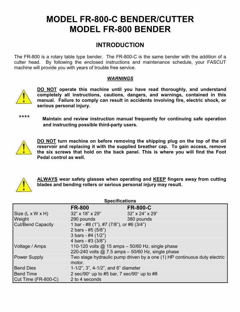
MODEL FR-800-C BENDER/CUTTER MODEL FR-800 BENDER
INTRODUCTION
The FR-800 is a rotary table type bender. The FR-800-C is the same bender with the addition of a cutter head. By following the enclosed instructions and maintenance schedule, your FASCUT machine will provide you with years of trouble free service.
WARNINGS
DO NOT operate this machine until you have read thoroughly, and understand completely all instructions, cautions, dangers, and warnings, contained in this manual. Failure to comply can result in accidents involving fire, electric shock, or serious personal injury.
**** Maintain and review instruction manual frequently for continuing safe operation
and instructing possible third-party users.
DO NOT turn machine on before removing the shipping plug on the top of the oil reservoir and replacing it with the supplied breather cap. To gain access, remove the six screws that hold on the back panel. This is where you will find the Foot Pedal control as well.
ALWAYS wear safety glasses when operating and KEEP fingers away from cutting blades and bending rollers or serious personal injury may result.
Specifications
FR-800 FR-800-C Size (L x W x H) 32” x 18” x 29” 32” x 24” x 29” Weight 290 pounds 380 pounds Cut/Bend Capacity 1 bar - #8 (1”), #7 (7/8”), or #6 (3/4”) 2 bars - #5 (5/8”) 3 bars - #4 (1/2”) 4 bars - #3 (3/8”) Voltage / Amps 110-120 volts @ 15 amps – 50/60 Hz, single phase 220-240 volts @ 7.5 amps – 50/60 Hz, single phase Power Supply Two stage hydraulic pump driven by a one (1) HP continuous duty electric
motor. Bend Dies 1-1/2”, 3”, 4-1/2”, and 6” diameter
Bend Time 2 sec/90 up to #5 bar, 7 sec/90 up to #8 Cut Time (FR-800-C) 2 to 4 seconds

OPERATION
DO NOT attempt to operate this machine until you have read thoroughly and understand completely all instructions, cautions, dangers, and warnings, contained in this manual.
ALWAYS WEAR SAFETY GLASSES when operating machine, or when working close to the machine when it is being operated by others. ALWAYS KEEP FINGERS AWAY from cutting blades and bending rollers.
PLUG UNIT INTO a 110-120 Volt outlet on a circuit with no less than a 20 amp breaker. When using an extension cord, never use less than 12 gauge wire. Runs of over 100 feet are not recommended. Excessive voltage drop at the unit will cause the motor to burn out.
Or if 220 Volt
WIRE UNIT TO a 220-240 volt, 50/60 cycle, 1 phase power source. Unit will draw approximately 8 amps. When using an extension cord, never use less than 14-guage wire. Excessive voltage drop at the unit will cause the motor to burn out.
1. GENERATOR MUST BE 5000 WATTS OR LARGER. Disable idle down feature so generator
engine is running at operating speed before turning on rebar cutter. 2. TURN ON using the toggle switch. In cold weather operations, turn unit on and allow oil to warm
up for 5 to 10 minutes before using. 3. ALWAYS TURN OFF unit when not in use. DO NOT allow unit to idle for long periods of time. 4. KEEP IN UPRIGHT POSITION to prevent loss of hydraulic oil from the oil tank breather cap. 5. DO NOT DROP machine as serious personal injury may result and damage to the machine is likely. 6. DO NOT PICK UP OR CARRY machine alone as serious personal injury may result. Unit has handles so (2) two people can properly and safely move machine.

7. TO BEND a bar or bars, first select the proper bending die using the following table:
Standard Hooks:
1-1/2” die N/A 3” die #3 and #4 rebar 4-1/2” die #5 and #6 rebar 6” die #7 and #8 rebar
Stirrup Hooks:
1-1/2” die #3 rebar
3” die #4 and #5 rebar 4-1/2” die #6 rebar
6” die #7 and #8 rebar
8. THE BENDING POST has four different positions. It is held in place with a large allen head cap screw in one of two threaded holes on the rotary table. The post can be rotated to two different positions per hole. Select the proper position depending on what diameter bar you are bending and what size bending die you are bending the bar on. It should become obvious which position the bending post should be put in. Select your bending die size and then lay your bar up against the die. Select the bending post position that gives the least amount of space between the post and bar. Tighten large allen head cap screw to secure the bending post in this position. Next, with the bar still in position and straight (parallel) to the table, loosen the large allen head cap screw that holds the bending support roller and move it forward so it touches the bar. Adjust this support so the bar is straight (parallel) to the table when you are bending. The machine is now set-up for bending your particular size rebar.
9. ADJUST THE BEND ANGLE by moving the bending angle adjustment lever on the side of the
machine to the required angle. After making a test bend, move the bending adjustment lever slightly either way to achieve the exact angle you require. Move the two stops up against the adjuster on each side to lock it at this angle. The machine will now reproduce this same angle until a different set-up is made to the machine.
10. SEISMIC STIRRUPS require 2 different bend angles. You can preset two bending angles by
positioning one stop for one of the angles and the other stop for the second angle. When bending, simply slide the adjuster back and forth to either stop depending on which angle you want to bend.
11. POSITION BAR INTO BENDER by feeding bar into machine from right to left. Hold the bar in
place with your right hand ONLY. DO NOT hold bar close to the adjustable support roller as the bar is drawn TOWARDS this roller when a bend is made. SERIOUS INJURY COULD RESULT.
ALWAYS KEEP HANDS CLEAR of all bending dies, the bending post, and the adjustable support roller when a bend is being made or SERIOUS INJURY COULD RESULT.

KEEP YOUR HANDS AWAY FROM ALL MOVING PARTS. REMOVE all loose clothing before operating machine.
12. HOLD DOWN FOOT PEDAL until the table stops and reverses direction. The table automatically
stops and reverses at your preset bending angle. Release the pedal at any time to reverse direction. After a bend has been made PULL on the bar to the RIGHT to keep it against the bending spool until the table has returned to the start position.
NEVER have one person work the foot pedal while another is holding or feeding bar into the machine. SERIOUS INJURY COULD RESULT.
______________________________________________________________________ 1. ALWAYS wear safety glasses when operating. 2. KEEP FINGERS AWAY from cutting blades at all times. 3. TURN THE SELECTOR on the side of the machine from BEND to CUT. 4. POSITION bar or bars between cutting blades. Bar must rest on the bottom of the cutter opening
as shown.
5. ADJUST THE BAR SUPPORT on the right side of the cutter so the bar is held perpendicular to
the cutting blades. Press the foot pedal until the cut is made and then release the pedal. DO NOT cut very short pieces (3” or shorter) as they could fly out and cause an accident. If you must cut short pieces, you must come up with a way to contain the cut pieces to prevent them from flying out and injuring someone.
6. CUTTING BLADES have 4 cutting edges. When one set of edges is worn, simply remove blade
securing bolts and rotate to the next sharp edge. To access the blade securing bolts for the blade that moves, simply turn on the machine and make sure Cut/Bend lever is in the CUT position. Press the foot pedal and when the ram has extended about ¾ of the way out, flip off the on/off switch and turn the motor off. The ram will stay in the extended position until the machine is turned back on again. Now you can access the blade securing bolts to rotate or exchange this blade. Carefully grind mushroomed edges flat if they prevent proper seating of the blade in its new
OPERATION OF CUTTER (on FR-800-C models)

position. DO NOT attempt to re-sharpen worn edges as you will destroy the temper (hardening) properties of the blade and it will be ruined.
DO NOT continue to cut with worn blades as damage to the machine or SERIOUS INJURY COULD RESULT.
7. OPTIONAL TYPE 801 CUTTING BLADE can be used when cutting a lot of #3 or #4 bar. Your
cutting times will be faster because the cutter takes less time to advance and makes contact with the bar sooner. REPLACE the regular “stationary” cutting blade with the Optional Type 801 cutting blade. NOTE: This blade must NEVER be installed in the “moving” blade position. As always, make certain the securing bolts are tight. Adjust the bar support to keep rebar at a 90 degree angle to the cutting blades. In order to cut bar over ½” in diameter, the Optional Type 801 blade must be removed from the “stationary” socket and replaced with a standard size cutting blade.
NEVER place hands or fingers near cutter while in operation or SERIOUS INJURY COULD RESULT.
______________________________________________________________________
DAILY MAINTENANCE
1. GREASE fitting on top of the shaft that holds the adjustable bending support roller. 2. GREASE fitting on the left side of the cutter head. (FR-800-C only) 3. TIGHTEN blade securing bolts before each use period. Turn on the machine and make sure
Cut/Bend lever is in the CUT position. Press the foot pedal and when the ram has extended about ¾ of the way out, flip off the on/off switch and turn the motor off. The ram will stay in the extended position until the machine is turned back on again. Use the allen wrench provided on the machine to tighten the two bolts for each blade. DO NOT cut with loose cutting blades or severe damage to the cutter and broken blades will result.
SERIOUS INJURY to operator could result from a broken blade. ALWAYS WEAR EYE PROTECTION WHEN USING MACHINE.
ANNUAL MAINTENANCE
1. DRAIN AND REPLACE OIL at least once a year or 200 operating hours, whichever comes first.
Allow unit to run for five minutes before draining to warm up the oil. Remove six screws that hold on the back panel. The drain plug is on the end of the oil tank. After draining and replacing plug, fill through the breather cap hole on top of the unit to within 1” of the top. (approx. 1-1/2 gallons) Use a quality hydraulic oil with an ISO VG-46 weight rating for general year round use. Use a heavier ISO VG-68 weight rating for continuous hot weather operation.

2. PRESSURE WASH MACHINE inside and out. Remove the front and rear cover plates to access the inside area of the machine. Using compressed air, blow dry the inside and outside components after washing.
3. INSPECT MACHINE FOR OIL LEAKS by turning on and running machine for a minimum of 15
minutes. During this time, cycle the bender a minimum of 10 times. If your machine has a cutter, cycle the cutter a minimum of 10 times as well. Turn off machine and with the front and rear cover plates still removed, use a flash light to look for any signs of hydraulic fluid leaking. Check the entire rotary actuator that moves the bender. Check the cutter hydraulic cylinder (if so equipped). Inspect around the chrome piston rod, and the rear body seal. Check all hydraulic lines and fittings. Oil can travel great distances so it is important to try to find the true source of the leak so that it can be repaired.
4. LUBRICATE ALL THREADED FASTENERS and inspect all wearable components. Remove the
bending post bolt, the bending support roller bolt, the cutter adjustable bar support bolt (if so equipped) and lubricate them liberally with a good quality anti-seize. Use lithium grease and lubricate the end bearings of the table rollers. Spray LPS rust inhibitor on all exposed metal parts to protect them from corrosion.
5. REASSEMBLE MACHINE AND TEST for proper operation and performance. To test the
hydraulic system set-up machine to bend a 1” bar around the 6” die. Set the bend adjuster to 180 degrees. Time the machine to bend a 1” bar 180 degrees. It should take a maximum of 18 to 20 seconds to complete this bend. Set up the cutter (if so equipped) to cut a 1” bar. Time the machine to cut a 1” bar. It should take a maximum of 5 seconds to complete this cut. If after these tests you find your machine taking longer than the times shown above, this is an indication that your hydraulic pump is showing signs of wear and may need to be replaced.
**** The FASCUT factory has very knowledgeable people on staff answering your phone calls.
They are trained in all facets of our machines operation and are very good at helping you determine exactly what is wrong with your machine. The factory stocks every component of all our machines and can assist you and ship any part to you immediately with easy instructions for you to repair your machine on-site.
100% MADE IN THE U.S.A.
We are proud to be able to offer you outstanding customer service to go along with the quality machines that FASCUT has produced for over 30 years.

OPTIONAL – REFERENCE FENCE ATTACHMENT The reference fence attachment consists of a 1” square tube inserted into receptacles that are welded to the machine. The position of the tube can be locked in place by tightening a thumb screw on one of the receptacles. Two paddle bar holders get slid onto the tube. Typically one is positioned to the left of the receptacle and one to the right like shown in the photo below. But the holders can be put anywhere you need to get the dimensions you want. Slide the paddle bars into their holders and position them either closer to or further away from the centerline of the rotary table. This will vary some depending on the size of bar and the bending die being used. The proper setting allows the bar to touch near the tip of the paddle so the bar slides off as soon as it begins bending. For a rectangular stirrup, set one paddle bar for the short dimension and the other for the long. Keep the thumb screw loose on the paddle bar closest to the rotary table and simply slide it back and forth as needed to bend up the rectangle.
WARNING: Make certain that the bending post will not hit a paddle bar when the table rotates. Move the paddle bar further to the left, away from the rotary table so there is clearance between the bending post and the paddle bar when the table rotates. Use lines
etched into the table to reference smaller dimensions. A “Sharpie” works great for this. The FR-800-C Bender/Cutter reference fence attachment has an additional paddle bar that is bolted to the end of the bar. This provides the material stop for cutting accurate lengths.
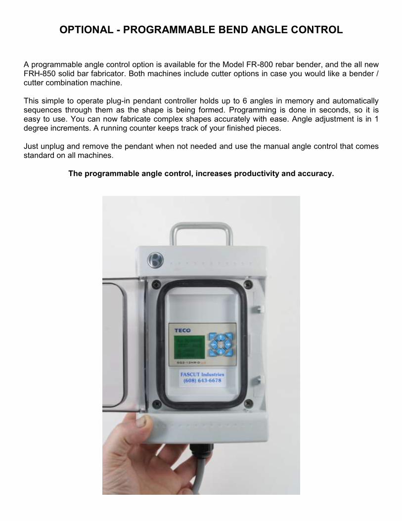
OPTIONAL - PROGRAMMABLE BEND ANGLE CONTROL
A programmable angle control option is available for the Model FR-800 rebar bender, and the all new FRH-850 solid bar fabricator. Both machines include cutter options in case you would like a bender / cutter combination machine. This simple to operate plug-in pendant controller holds up to 6 angles in memory and automatically sequences through them as the shape is being formed. Programming is done in seconds, so it is easy to use. You can now fabricate complex shapes accurately with ease. Angle adjustment is in 1 degree increments. A running counter keeps track of your finished pieces. Just unplug and remove the pendant when not needed and use the manual angle control that comes standard on all machines.
The programmable angle control, increases productivity and accuracy.

Operation of Optional Programmable Angle Control If the programmable angle control is not plugged in, you control the bend angle manually by adjusting the lever control on the side of the machine. IMPORTANT: When you want to use the programmable angle control, plug it in and move the manual lever control on the machine all the way to the right to180 degrees and lock in place. ADJUSTING PRESET VALUE Pushing the DOWN arrow on the control brings you to the PRESET value. Using the LEFT and RIGHT arrows, adjust the PRESET value between 18 to 37. Use this chart to determine what PRESET value to use. If, after selecting the recommended preset, your bend is either too much or not enough; you can use a higher or lower preset value to correct this. Each number increases or decreases the bend by 1 degree.
Rebar Size Die Dia. Preset
#3 (3/8”) 1½” 27
#3 (3/8”) 3” 32
#4 (1/2”) 1½” 22
#4 (1/2”) 3” 27
#5 (5/8”) 3” 23
#5 (5/8”) 4½” 32
#6 (3/4”) 4½” 30
#6 (3/4”) 6” 34
#7 (7/8”) 6” 29
#8 (1”) 6” 24
PROGRAMMING ANGLES Pushing the DOWN arrow a second time brings you to the first angle; A1. Use the LEFT and RIGHT arrows to adjust the angle value for the degrees of bend you want. Each time you push the DOWN arrow you advance to the next angle up to A6. IMPORTANT: When finished programming you MUST push the UP arrow to put the controller into RUN mode. If you forget, nothing will happen when you press the foot pedal. OPERATION The controller will automatically sequence through the angles until it reads a “0” angle. Then the controller goes back to A1 and starts over. Here is an example: A1 = 90; A2 = 90; A3 = 45; A4 = 0; A5 = 0; A6 = 0 The first time you push the foot pedal the table will rotate to bend 90 degrees. The second time you push the foot pedal the table will rotate to bend 90 degrees. The third time the table will rotate to bend 45 degrees. At this point a counter on the RUN line will advance 1 count and the controller goes back to A1 to start the sequence over again. If only 1 angle is required, it only needs to be programmed into A1. Set A2 thru A6 at 0. The machine will repeat this bend indefinitely.

CALCULATING THE ADJUSTMENT FACTOR FOR BENDING DIFFERENT SIZES OF REBAR
For #3 bar bent on 1-1/2" diameter die - L minus 1-1/4" = M For #4 bar bent on 3" diameter die - L minus 2-1/4" = M For #6 bar bent on 4-1/2" diameter die - L minus 3-1/4" = M For #8 bar bent on 6" diameter die - L minus 4-1/4" = M
Bending a Stirrup Refer to the series of pictures showing a standard 5-bend stirrup being bent from start to finish. In this example we are bending a 10" square stirrup with 5-1/4" long tails out of #4 bar on the 3" diameter die. Use the adjustment factor above to determine how to set the reference stop. 10"(L) minus 2-1/4" = 7-3/4"(M). Add up the sides of the stirrup: 5-1/4"+10"+10"+10"+10"+5-1/4" = 50-1/2". Cut one bar this long and make the stirrup. The bar will be too long because less bar is needed to make a round corner than a square one. After the stirrup is made, measure how much the bar is too long and deduct this from the original 50-1/2" length. Cut your bars to this new length and the stirrup will now come together properly after making bend #5.

Stirrup Bending Sequence
Bend #1 – Line up end of bar with mark on table and make 90 degree bend.

Bend #2 – Do the same on the other end of the bar.

Bend #3 – Move bent end over to the reference fence.

Bend #4 – Move bend #3 over to the reference fence. This time, lift up slightly on the “hook” end.
This will help the “hook” end travel over the other “hook” end when making bend #5.

Bend #5 – Stirrup comes together.

FASCUT™ Model FR-800 or FR-800-C Rebar Fabricators
November 1, 2014
Parts List
Index #
Description Part # Price/ea. Qty Req’d
FR-800-C Rebar Fabricator – Complete FR-800 Rebar Fabricator – Complete
FR800C FR800
6,450.00 4,895.00
1 Allen wrench, ¼” 80310 3.36 1
2 Allen wrench, ¾” 80319 19.40 1
3
FR-800 front cover panel FR-800-C front cover panel
80604 80606
39.00 39.00
1 1
4 Rear cover panel 80608 39.00 1
5 Frame 80612 735.00 1
6 Top cover panel 80613 59.00 1
7 Table roller 80615 24.66 2
8 Bar rest support – FR-800-C 80616 13.27 1
9 Cooling fan 80618 42.00 1
10 Selector valve, cut-bend 80623 117.28 1
11 Selector valve, cut-bend – handle only 80624 9.70 1
12 Bar rest assembly – FR-800-C 80710 13.80 1
12 Safety cover plate – FC-800 80720 27.64 1
13 Thumb screw for stop bar attachment 77554 1.15 1
“A” See Breakdown “A”
“B” See Breakdown “B”
“F” See Breakdown “F”
Rota
ry B
en
din
g C
om
pon
ents
B
reakd
ow
n A
FASCUT™ Model FR-800 or FR-800-C
Rebar Fabricator
Parts List
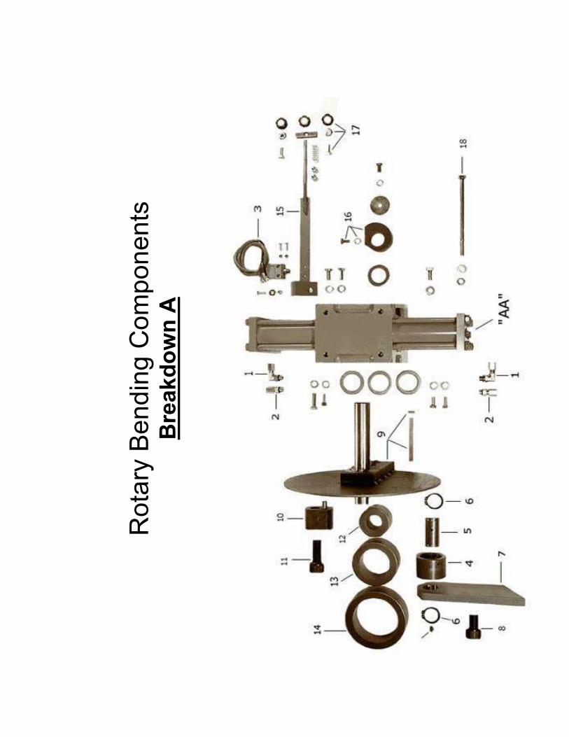
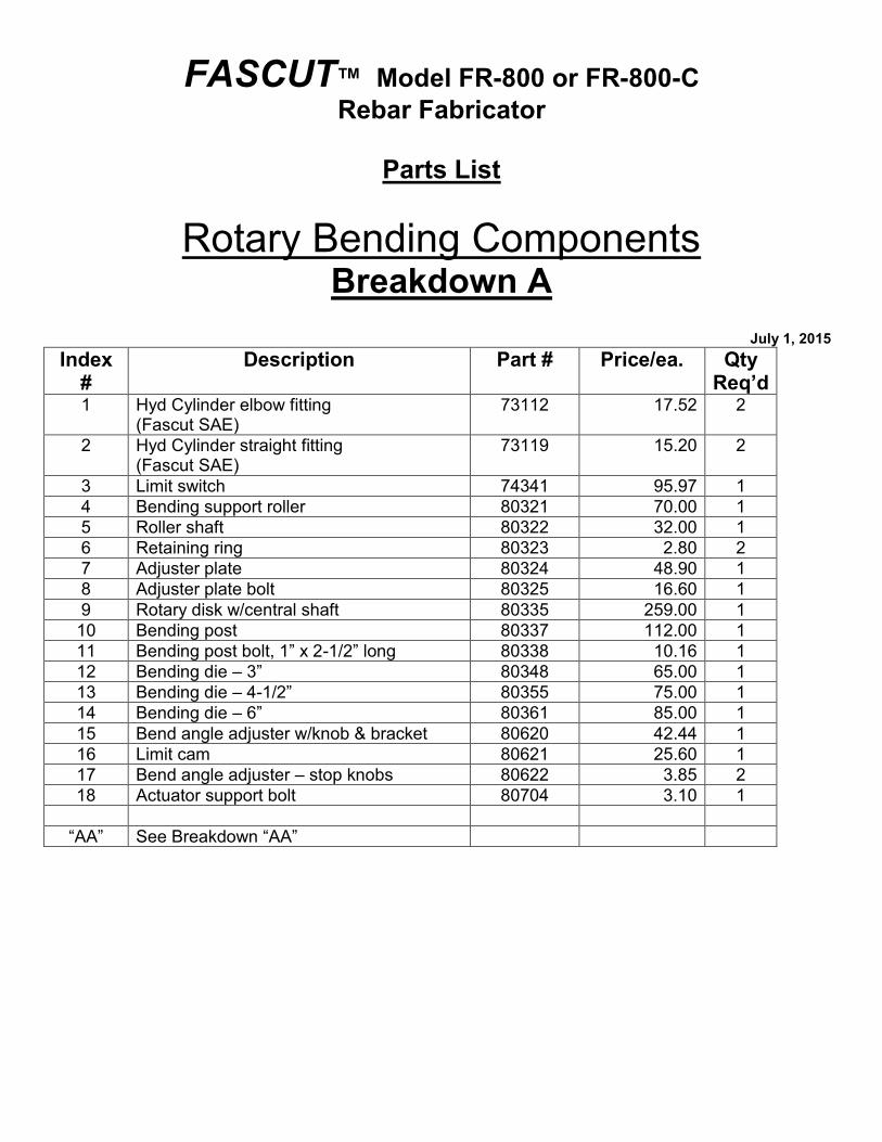
Rotary Bending Components Breakdown A
July 1, 2015
Index #
Description Part # Price/ea. Qty Req’d
1 Hyd Cylinder elbow fitting (Fascut SAE)
73112 17.52 2
2 Hyd Cylinder straight fitting (Fascut SAE)
73119 15.20 2
3 Limit switch 74341 95.97 1
4 Bending support roller 80321 70.00 1
5 Roller shaft 80322 32.00 1
6 Retaining ring 80323 2.80 2
7 Adjuster plate 80324 48.90 1
8 Adjuster plate bolt 80325 16.60 1
9 Rotary disk w/central shaft 80335 259.00 1
10 Bending post 80337 112.00 1
11 Bending post bolt, 1” x 2-1/2” long 80338 10.16 1
12 Bending die – 3” 80348 65.00 1
13 Bending die – 4-1/2” 80355 75.00 1
14 Bending die – 6” 80361 85.00 1
15 Bend angle adjuster w/knob & bracket 80620 42.44 1
16 Limit cam 80621 25.60 1
17 Bend angle adjuster – stop knobs 80622 3.85 2
18 Actuator support bolt 80704 3.10 1
“AA” See Breakdown “AA”

Rota
ry H
yd
raulic
Actu
ato
r B
reakd
ow
n A
A

FASCUT™ Model FR-800 or FR-800-C
Rebar Fabricator
Parts List
Rotary Hydraulic Actuator Breakdown AA
July 1, 2015
Index #
Description Part # Price/ea. Qty Req’d
Rotary hydraulic actuator - Complete Includes: #1-- #6, #8, #10-- #17, #23-- #26
80500 1767.00
Seal kit – Complete Includes: #3, #10, #13-- #15, #23-- #26
80540 47.04
1 Housing 80510 775.00 1
2 Bearing 80522 35.00 2
3 Bearing cap o-ring seal 80530 2.08 1
4 Bearing cap 80513 62.00 1
5 Pinion 80520 159.00 1
6 Tie rod nut 80515 .89 16
8 Tie rod 80514 5.20 16
10 Pinion o-ring seal 80531 2.08 2
11 Relief valve 80516 4.95 1
12 Cylinder tube – serial #18398 and up 80511 61.00 4
Cylinder tube – serial #18397 and down 80542 61.00 4
13 Piston back-up ring 80532 2.24 8
14 Piston o-ring seal 80533 1.60 4
15 Cylinder tube o-ring seal 80534 .96 4
16 Piston rack – serial #18398 and up 80521 232.00 2
Piston rack – serial #18397 and down **** No longer available ****
Must order #12 (80511) and #16 (80521)
17 Cylinder head 80512 69.00 4
23 Cylinder head back-up ring 80535 1.92 4
24 Cylinder head o-ring seal 80536 1.12 4
25 Bearing cap set screw 80517 .32 1
26 Bearing cap nylon pellet 80518 .16 1

Cutte
r H
ead
an
d H
ydra
ulic
Cylin
der
Bre
akd
ow
n B

FASCUT™ Model FR-800-C or FC-800 Rebar Fabricators
Parts List
Cutter Head and Hydraulic Cylinder Breakdown B
November 1, 2012
Index #
Description Part # Price/ea. Qty Req’d
Hydraulic cylinder – Complete Includes: #1, #2, #4, #5, #6, #7
80430 711.00
1 Cylinder body w/back plate 80432 434.00 1
2 Piston & rod assy. w/seal and loader 80434 310.00 1
3 Piston seal w/square loader ring 80436 34.90 1
4 Back body seal 80438 9.00 1
5 Nylon bearing 80440 4.95 1
6 Rod seal 80442 15.50 1
7 Key, ½” sq. #18380, #918 and up 80451 14.50 1
Key, ½” sq. #18379, #917 and down 80452 14.50 1
8 Cutter head casting 80700 748.00 1
9 Cylinder to cutter head bolts/lock washers 80705 1.20 8
10 Bar rest -- FC-800 80710 13.80 1
11 Bar support (adjustable) 80715 21.00 1
12 Safety cover plate – FC-800 80720 27.64 1
Safety cover plate – FR-800-C 80721 27.64 1
13 Safety decal for cover plate 78643 .98 1
14 Safety cover plate attach screw/washer 80723 .15 2
15 Grease fitting – elbow 82548 1.94 1
16 Cutting blades 800 type / set FAS800 85.00 1
special Cutting blade 800 chain modified FAS800CM 62.50 1
special Cutting blade 801 type FAS801 64.00 1
special Cutting blade 801 chain modified FAS801CM 84.00 1
17 Blade bolts & lockwashers / set 85670 2.30 1
Special tools for cylinder dis-assembly
Spanner wrench – flat 80461 15.00
Spanner wrench – extended 80462 30.00

Hyd
raulic
Pow
er
Unit
Bre
akd
ow
n C

FASCUT™ Model FR-800-C & FR-800 Rebar Fabricators
Parts List
Hydraulic Power Unit Breakdown C
November 1, 2012 Index
# Description Part # Price/ea. Qty
Req’d Hydraulic Power Unit – Complete 73405 1,550.00
1 Breather cap 71062 9.00 1
2 Cord grip 71814 3.85 3
3 Hyd. Pump only – serial #6506 and up (except for #6548 thru #6568)
73424 514.00 1
4 Hyd. Pump elbow fitting 73662 17.94 2
5 Hyd. Pump mounting bolt 73844 2.25 4
6 Hyd. Pump oil seal o-ring 73519 .30 1
7 Hyd. Pump pressure seal o-ring 73546 .25 1
10 Electric Motor – serial #8382 and up 75705 541.00 1
Electric Motor – serial #8381 and down to #6506 (except for #6548 thru #6568)
75706 673.00
Electric Motor (Delta) – serial #6200 thru #6505 and #6548 thru #6568
75907 549.00
11 Motor drive coupling 75715 17.72 1
Motor drive coupling (Delta) 75914 17.72
12 Motor fan shroud 75721 47.50 1
13 Motor fan 75734 41.95 1
14 Motor fan retaining ring 75735 .50 1
15 Motor case thru bolt 75797 2.25 4
16 Motor shaft bearing 75872 16.02 2
17 Motor spring washer 75797 1.25 1
18 Motor starting switch 75889 29.50 1
Oil/quart – ISO-46 hydraulic oil 76046 7.60 6
20 Oil drain plug 76245 .79 1
21 Oil tank 76406 89.00 1
22 Oil tank o-ring 76421 9.00 1
23 Oil tank magnet 76256 4.15 1
24 Starting capacitor 77253 18.07 1
25 Valve, directional 78919 94.35 1
26 Valve coil, 110-v 78937 71.40 1
27 Valve coil, 24-v for 220-v unit 78938 77.50 1
28 Valve, kick-down 78989 102.00 1

Hyd
rau
lic L
ines &
Fittin
gs –
FR
-80
0-C
B
reakd
ow
n D

FASCUT™ Model FR-800-C Rebar Fabricator
Parts List
Hydraulic Lines & Fittings Breakdown D
November 1, 2012
Index #
Description Part # Price/ea.
Qty Req’d
FR-800-C cutter / bender
1 Pressure line; goes from hydraulic power unit to center of three-way valve
80481 10.50 1
2 Return line; goes from front port of cutter cylinder to tee in hydraulic power unit
80482 10.50 1
3 Return line; goes from tee in hydraulic power unit to SAE union tee
80483 10.50 1
4 Pressure line; goes from rear port of cutter cylinder to three-way valve
80484 10.50 1
5 Return line; goes from SAE union tee to
rotary actuator cylinder A
80485 10.50 1
6 Pressure line; goes from tee in three-way
valve to rotary actuator cylinder B
80486 10.50 1
7 Pressure line; goes from tee in three-way
valve to rotary actuator cylinder C
80487 10.50 1
8 Return line; goes from SAE union tee to
rotary actuator cylinder D
80488 10.50 1
9 Three–way valve – cut/bend selector 80623 117.28 1
10 Fitting; pipe thread male branch T (NPT) 73121 15.23 1
11 Fitting; union T (SAE) 73122 18.43 1
12 Fitting; o-ring run T (SAE) 73124 27.62 1
13 Fitting; o-ring straight connector (SAE) 73119 15.20 4
14 Fitting; o-ring elbow connector (SAE) 73112 17.52 3
15 Fitting; pipe thread male straight connector (NPT)
73120 15.20 2

Hyd
raulic
Lin
es &
Fittin
gs –
FR
-80
0
Bre
akd
ow
n D
D

FASCUT™ Model FR-800 Rebar Fabricator
Parts List
Hydraulic Lines & Fittings Breakdown DD
November 1, 2012
Index #
Description Part # Price/ea.
Qty Req’d
FR-800 bender
1 Pressure line; goes from hydraulic power unit to center of (SAE) union T
80463 10.50 1
2 Fitting; cap (SAE) 73123 3.25 1
3 Return line; goes from tee in hydraulic power unit to (SAE) union tee
80483 10.50 1
5 Return line; goes from SAE union tee to
rotary actuator cylinder A
80485 10.50 1
6 Pressure line; goes from tee in three-way
valve to rotary actuator cylinder B
80486 10.50 1
7 Pressure line; goes from tee in three-way
valve to rotary actuator cylinder C
80487 10.50 1
8 Return line; goes from SAE union tee to
rotary actuator cylinder D
80488 10.50 1
11 Fitting; union T (SAE) 73122 18.43 1
12 Fitting; o-ring run T (SAE) 73124 27.62 1
13 Fitting; o-ring straight connector (SAE) 73119 15.20 4
14 Fitting; o-ring elbow connector (SAE) 73112 17.52 3

Ele
ctr
ica
l C
om
po
ne
nts
B
reakd
ow
n E

FASCUT™ Model FR-800-C & FR-800 Rebar Fabricators
Parts List
Electrical Components Breakdown E
November 1, 2012 Index
# Description Part # Price/e
a. Qty
Req’d 1 Electric box cover – 600 or 800 66743 6.98 1
2 Foot pedal socket 72373 23.66 1
3 Liquid Tight tubing 74488 3.96 1
4 Liquid Tight fitting – straight 74492 2.20 1
5 Liquid Tight fitting – elbow 74493 3.92 1
6 **
On / Off switch – 110v On / Off switch – 220v On / Off switch boot
76619 76620 76633
8.12 9.60 2.97
1 *1* 1
7 Power cord w/plug – 110v 76745 12.28 1
8 **
Relay, 110v Relay, 24v
76951 76952
23.55 30.39
1 *1*
9 Relay socket 76953 7.80 1
10 Relay retainer clip 76954 .84 1
11 Terminal block 77837 4.85 1
** Transformer 24 VAC (not shown) 77875 29.50 *1*
* * If wired for 220 volts

Foot
Ped
al C
on
tro
l B
reakd
ow
n F

FASCUT™ Model FR-800-C & FR-800 Rebar Fabricators
Parts List
Foot Pedal Control Breakdown F
November 1, 2012 Index
# Description Part # Price/e
a. Qty
Req’d Foot pedal control - Complete 72365 129.00
1 Foot pedal vinyl boot 72366 9.80 1
2 Foot pedal cord w/plug 72369 18.79 1
3 Cord grip ½” – fits Linemaster 72371 3.85 1
4 Cord grip ¾” – fits Square D 72372 5.85 1
Foot pedal socket – See Breakdown E-2 72373 23.66 1
5 Foot pedal switch (Linemaster Clipper) Serial number: 18573 & up
72394 16.95 1
6 Foot pedal switch (Linemaster Hercules) Serial number: 18572 & down
72395 16.95 1
7 Foot pedal switch (Square D) Serial number: 18572 & down also used
72398 59.41 1
Linemaster foot pedals are Orange in color Square D foot pedals are Yellow in color

WIRING DIAGRAMS
Pressing the foot switch completes the circuit to energize the valve coil. The limit switch is spring loaded and normally open. It is triggered by a cam on the rotary disk shaft. Moving the angle adjuster from 0 deg. to 180 deg. positions the limit switch closer to or farther away from the cam. This controls how much the rotary disk must turn before it triggers the limit switch. When the limit switch is triggered, it energizes the relay which will open the valve coil circuit, causing the rotary disk to rotate back to the starting point.

TROUBLESHOOTING
TROUBLE PROBABLE CAUSE REMEDY
Motor will not start
1. No power to unit. 2. Power cord or plug damaged. 3. On/off switch bad. 4. Motor wire connections loose.
1. Check supply cord, fuses, or circuit breaker.
2. Replace power core w/plug.
3. Replace on/off switch. 4. Tighten motor wire
connections.
Motor hums, then blows circuit breaker, or motor is smoking
1. Extension cord too long or not heavy enough.
2. Starting capacitor bad. 3. Starting switch bad. 4. Generator too small. 5. Generator running at idle
before starting unit. 6. Motor windings burnt out.
1. Extension cord must be min. 12 gauge wire and no longer than 100 feet.
2. Replace starting capacitor.
3. Replace starting switch. 4. Use a 5 KW generator or
larger. 5. Turn off or disconnect idle
down feature. 6. Replace motor.
Motor runs, but nothing happens when foot pedal is depressed.
1. Relay has fallen out of its socket.
2. Relay socket is broken. 3. Bend angle adjuster is moved
over to “0” degrees. 4. Limit switch is bad. 5. Relay is bad. 6. Foot pedal cord or plug is
damaged. 7. Jack is bad. 8. Switch inside foot pedal is
bad. 9. Loose wire. 10. Valve coil is bad. 11. Directional valve is bad.
1. Plug relay back into socket.
2. Replace relay socket. 3. Move the bend angle
adjuster away from “0” degrees.
4. Replace limit switch. 5. Replace relay. 6. Replace foot pedal cord
w/plug. 7. Replace jack. 8. Replace inside switch. 9. Check all wiring for loose
connections. 10. Replace valve coil. 11. Replace directional valve.
Cutting blade bolts breaking
1. Cutting blade bolts are loose. 2. Cutting blades are dull.
1. Retighten blade bolts regularly.
2. Turn blades to new cutting edge or replace blades.

Cutting blades breaking
1. Blades are dull. 2. Blade bolts are loose. 3. Rebar is being dropped into
the cutter. 4. You are cutting “no grade”
steel 5. Bar is being cut on the top
corner of the cutting blade
1. Turn blades to a new edge sooner.
2. Check blade bolts for tightness more often.
3. Place rebar into the cutter with greater care.
4. Only cut grade 40 or grade 60 rebar.
5. Bar must rest on the bottom of the cutter opening.
Oil is leaking 1. Hydraulic tubes and fittings are loose or damaged.
2. Hydraulic cylinder body seals or rod seal is leaking.
3. Oil is leaking from rotary actuator.
1. Check fittings for tightness. Replace damaged fittings or tube.
2. Install new body and/or rod seals in hydraulic cylinder.
3. Install new seals and o-rings in rotary actuator.
Bending or Cutting is slow and lacks power
1. Oil level is low. 2. Oil is contaminated. 3. Hydraulic pump is worn.
1. Add oil to tank. 2. Drain and refill oil tank with
fresh ISO-46 hydraulic oil. 3. Replace hydraulic pump.

FASCUT® Industries, Inc.
LIMITED WARRANTY
This product has been thoroughly inspected and tested before leaving the factory. It is guaranteed against defective workmanship and materials for a period of 1 year to the original owner. Should any trouble develop, return defective part transportation prepaid to the factory. If inspection shows trouble is caused by defective workmanship or material, all repairs will be made without charge and returned, transportation prepaid. The guarantee does not apply where: repairs or attempted repairs have been made by persons other than the factory; repairs are due to normal wear; the tool has been abused or in an accident; misuse is evident – caused by overloading the tool beyond its rated capacity; use on improper voltage or current; use of the tool after partial failure or use with improper accessories. This warranty is in lieu of all other warranties, expressed or implied, and there are no warranties on merchantability or fitness for a particular purpose. In no event shall seller be liable for incidental, consequential or special damages. This warrantee is void if Warrantee/Registration card is not filled out and returned. This warranty gives you specific legal rights, and you may also have other rights, which vary from state to state. SERIAL NUMBER ______________________ DATE ____________________
FASCUT® Industries, Inc. 7248 Inama Rd.
Sauk City, WI 53583
Phone: (608) 643-6678 Fax: (608) 643-2682
www.fascut.com