fast crash recovery in ramcloud - sigops
TRANSCRIPT

Fast Crash Recovery in RAMCloud
Diego Ongaro, Stephen M. Rumble, Ryan Stutsman,John Ousterhout, and Mendel Rosenblum
Stanford University
ABSTRACTRAMCloud is a DRAM-based storage system that provides inexpensive durability and availability byrecovering quickly after crashes, rather than storing replicas in DRAM. RAMCloud scatters backupdata across hundreds or thousands of disks, and it harnesses hundreds of servers in parallel to recon-struct lost data. The system uses a log-structured approach for all its data, in DRAM as well as ondisk; this provides high performance both during normal operation and during recovery. RAMCloudemploys randomized techniques to manage the system in a scalable and decentralized fashion. In a60-node cluster, RAMCloud recovers 35 GB of data from a failed server in 1.6 seconds. Our mea-surements suggest that the approach will scale to recover larger memory sizes (64 GB or more) inless time with larger clusters.
Categories and Subject DescriptorsD.4.7 [Operating Systems]: Organization and Design—Distributed systems; D.4.2 [Operating Sys-tems]: Storage Management—Main memory; D.4.5 [Operating Systems]: Reliability—Fault-tolerance;D.4.8 [Operating Systems]: Performance—Measurements
General TermsDesign, Measurement, Performance, Reliability, Experimentation
KeywordsStorage systems, Main memory databases, Crash recovery, Scalability
1. INTRODUCTIONThe role of DRAM in storage systems has been increasing rapidly in recent years, driven by the needsof large-scale Web applications. These applications manipulate very large datasets with an intensitythat cannot be satisfied by disks alone. As a result, applications are keeping more and more of theirdata in DRAM. For example, large-scale caching systems such as memcached [3] are being widelyused (in 2009 Facebook used a total of 150 TB of DRAM in memcached and other caches for a
Permission to make digital or hard copies of all or part of this work for personal or classroom use is grantedwithout fee provided that copies are not made or distributed for profit or commercial advantage and that copiesbear this notice and the full citation on the first page. To copy otherwise, to republish, to post on servers or to redistribute to lists, requires prior specific permission and/or a fee. SOSP '11, October 23-26, 2011, Cascais, Portugal. Copyright © 2011 ACM 978-1-4503-0977-6/11/10 ... $10.00.

database containing 200 TB of disk storage [15]), and the major Web search engines now keep theirsearch indexes entirely in DRAM.
Although DRAM’s role is increasing, it still tends to be used in limited or specialized ways. In mostcases DRAM is just a cache for some other storage system such as a database; in other cases (such assearch indexes) DRAM is managed in an application-specific fashion. It is difficult for developers touse DRAM effectively in their applications; for example, the application must manage consistencybetween caches and the backing storage. In addition, cache misses and backing store overheads makeit difficult to capture DRAM’s full performance potential.
RAMCloud is a general-purpose storage system that makes it easy for developers to harness the fullperformance potential of large-scale DRAM storage. It keeps all data in DRAM all the time, so thereare no cache misses. RAMCloud storage is durable and available, so developers need not managea separate backing store. RAMCloud is designed to scale to thousands of servers and hundreds ofterabytes of data while providing uniform low-latency access (5-10 μs round-trip times for small readoperations).
The most important factor in the design of RAMCloud was the need to provide a high level of dura-bility and availability without impacting system performance. Replicating all data in DRAM wouldhave solved some availability issues, but with 3x replication this would have tripled the cost and en-ergy usage of the system. Instead, RAMCloud keeps only a single copy of data in DRAM; redundantcopies are kept on disk or flash, which is both cheaper and more durable than DRAM. However, thismeans that a server crash will leave some of the system’s data unavailable until it can be reconstructedfrom secondary storage.
RAMCloud’s solution to the availability problem is fast crash recovery: the system reconstructsthe entire contents of a lost server’s memory (64 GB or more) from disk and resumes full servicein 1-2 seconds. We believe this is fast enough to be considered “continuous availability” for mostapplications.
This paper describes and evaluates RAMCloud’s approach to fast recovery. There are several inter-esting aspects to the RAMCloud architecture:
• Harnessing scale: RAMCloud takes advantage of the system’s large scale to recover quicklyafter crashes. Each server scatters its backup data across all of the other servers, allowing thou-sands of disks to participate in recovery. Hundreds of recovery masters work together to avoidnetwork and CPU bottlenecks while recovering data. RAMCloud uses both data parallelismand pipelining to speed up recovery.
• Log-structured storage: RAMCloud uses techniques similar to those from log-structured filesystems [21], not just for information on disk but also for information in DRAM. The log-structured approach provides high performance and simplifies many issues related to crashrecovery.
• Randomization: RAMCloud uses randomized approaches to make decisions in a distributedand scalable fashion. In some cases randomization is combined with refinement: a serverselects several candidates at random and then chooses among them using more detailed infor-mation; this provides near-optimal results at low cost.
• Tablet profiling: RAMCloud uses a novel dynamic tree structure to track the distribution ofdata within tables; this helps divide a server’s data into partitions for fast recovery.
We have implemented the RAMCloud architecture in a working system and evaluated its crash recov-ery properties. Our 60-node cluster recovers in 1.6 seconds from the failure of a server with 35 GBof data, and the approach scales so that larger clusters can recover larger memory sizes in less time.
Measurements of our randomized replica placement algorithm show that it produces uniform alloca-tions that minimize recovery time and that it largely eliminates straggler effects caused by varyingdisk speeds.
Overall, fast crash recovery allows RAMCloud to provide durable and available DRAM-based stor-age for the same price and energy usage as today’s volatile DRAM caches.
2. RAMCLOUDCrash recovery and normal request processing are tightly intertwined in RAMCloud, so this sec-tion provides background on the RAMCloud concept and the basic data structures used to processrequests. We have omitted some details because of space limitations.
2.1 BasicsRAMCloud is a storage system where every byte of data is present in DRAM at all times. Thehardware for RAMCloud consists of hundreds or thousands of off-the-shelf servers in a single data-center, each with as much DRAM as is cost-effective (24 to 64 GB today). RAMCloud aggregatesthe DRAM of all these servers into a single coherent storage system. It uses backup copies on disk orflash to make its storage durable and available, but the performance of the system is determined byDRAM, not disk.
The RAMCloud architecture combines two interesting properties: low latency and large scale. First,RAMCloud is designed to provide the lowest possible latency for remote access by applications inthe same datacenter. Our goal is end-to-end times of 5-10 μs for reading small objects in datacenterswith tens of thousands of machines. This represents an improvement of 50-5,000x over existingdatacenter-scale storage systems.
Unfortunately, today’s datacenters cannot meet RAMCloud’s latency goals (Ethernet switches andNICs typically add at least 200-500 μs to round-trip latency in a large datacenter). Thus we use low-latency Infiniband NICs and switches in our development environment as an approximation to thenetworking hardware we hope will be commonplace in a few years; this makes it easier to explorelatency issues in the RAMCloud software. The current RAMCloud system supports 5 μs reads in asmall cluster, and each storage server can handle about 1 million small read requests per second.
The second important property of RAMCloud is scale: a single RAMCloud cluster must supportthousands of servers in order to provide a coherent source of data for large applications. Scale createsseveral challenges, such as the likelihood of frequent component failures and the need for distributeddecision-making to avoid bottlenecks. However, scale also creates opportunities, such as the abilityto enlist large numbers of resources on problems like fast crash recovery.
RAMCloud’s overall goal is to enable a new class of applications that manipulate large datasets moreintensively than has ever been possible. For more details on the motivation for RAMCloud and someof its architectural choices, see [18].
2.2 Data ModelThe current data model in RAMCloud is a simple key-value store. RAMCloud supports any numberof tables, each of which contains any number of objects. An object consists of a 64-bit identifier, avariable-length byte array (up to 1 MB), and a 64-bit version number. RAMCloud provides a simpleset of operations for creating and deleting tables and for reading, writing, and deleting objects withina table. Objects are addressed with their identifiers and are read and written in their entirety. There isno built-in support for atomic updates to multiple objects, but RAMCloud does provide a conditionalupdate (“replace the contents of object O in table T only if its current version number is V ”), whichcan be used to implement more complex transactions in application software. In the future we plan toexperiment with more powerful features such as indexes, mini-transactions [4], and support for largegraphs.
Coordinator
Master
Backup
Master
Backup
Master
Backup
Master
Backup. . .
Client Client Client Client. . .
Datacenter Network
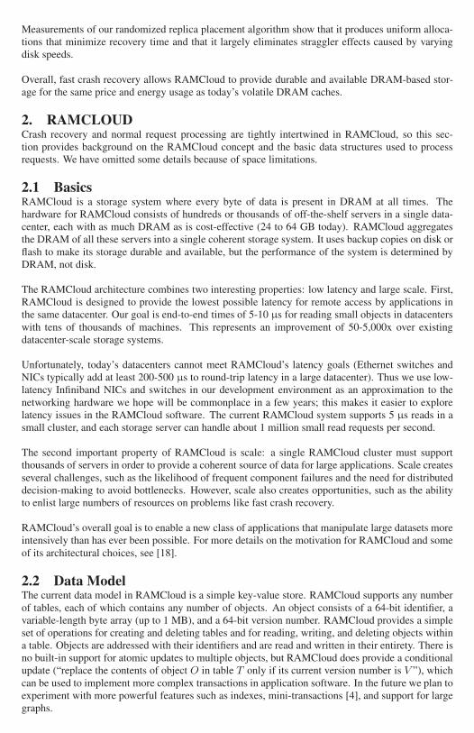
Figure 1: RAMCloud cluster architecture. Each storage server contains a master and a backup. A centralcoordinator manages the server pool and tablet configuration. Client applications run on separate machines andaccess RAMCloud using a client library that makes remote procedure calls.
2.3 System StructureAs shown in Figure 1, a RAMCloud cluster consists of a large number of storage servers, each ofwhich has two components: a master, which manages RAMCloud objects in its DRAM and servicesclient requests, and a backup, which stores redundant copies of objects from other masters usingits disk or flash memory. Each RAMCloud cluster also contains one distinguished server called thecoordinator. The coordinator manages configuration information such as the network addresses ofthe storage servers and the locations of objects; it is not involved in most client requests.
The coordinator assigns objects to storage servers in units of tablets: consecutive key ranges within asingle table. Small tables are stored in their entirety on a single storage server; larger tables are splitacross multiple servers. Client applications do not have control over the tablet configuration; however,they can achieve some locality by taking advantage of the fact that small tables (and adjacent keys inlarge tables) are stored together on a single server.
The coordinator stores the mapping between tablets and storage servers. The RAMCloud clientlibrary maintains a cache of this information, fetching the mappings for each table the first time itis accessed. Clients can usually issue storage requests directly to the relevant storage server withoutinvolving the coordinator. If a client’s cached configuration information becomes stale because atablet has moved, the client library discovers this when it makes a request to a server that no longercontains the tablet, at which point it flushes the stale data from its cache and fetches up-to-dateinformation from the coordinator. Clients use the same mechanism during crash recovery to find thenew location for data.
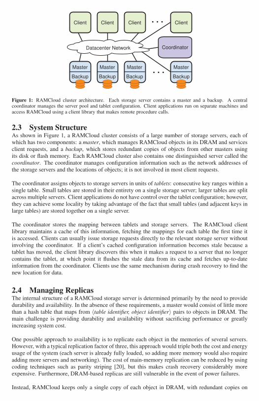
2.4 Managing ReplicasThe internal structure of a RAMCloud storage server is determined primarily by the need to providedurability and availability. In the absence of these requirements, a master would consist of little morethan a hash table that maps from 〈table identifier, object identifier〉 pairs to objects in DRAM. Themain challenge is providing durability and availability without sacrificing performance or greatlyincreasing system cost.
One possible approach to availability is to replicate each object in the memories of several servers.However, with a typical replication factor of three, this approach would triple both the cost and energyusage of the system (each server is already fully loaded, so adding more memory would also requireadding more servers and networking). The cost of main-memory replication can be reduced by usingcoding techniques such as parity striping [20], but this makes crash recovery considerably moreexpensive. Furthermore, DRAM-based replicas are still vulnerable in the event of power failures.
Instead, RAMCloud keeps only a single copy of each object in DRAM, with redundant copies on

Master
Hash table
In-Memory Log
Backup
DiskBuffered Segment
Backup
DiskBuffered Segment
Backup
DiskBuffered Segment
1.Process write
request
2. Append object to log and
update hash table
3. Replicate object
to backups
4. Respond to
write request
Figure 2: When a master receives a write request, it updates its in-memory log and forwards the new data toseveral backups, which buffer the data in their memory. The data is eventually written to disk or flash in largebatches. Backups must use an auxiliary power source to ensure that buffers can be written to stable storage aftera power failure.
secondary storage such as disk or flash. This makes replication nearly free in terms of cost and energyusage (the DRAM for primary copies will dominate both of these factors), but it raises two issues.First, the use of slower storage for backup might impact the normal-case performance of the system(e.g., by waiting for synchronous disk writes). Second, this approach could result in long periods ofunavailability or poor performance after server crashes, since the data will have to be reconstructedfrom secondary storage. Section 2.5 describes how RAMCloud solves the performance problem, andSection 3 deals with crash recovery.
2.5 Log-Structured StorageRAMCloud manages object data using a logging approach. This was originally motivated by thedesire to transfer backup data to disk or flash as efficiently as possible, but it also provides an efficientmemory management mechanism, enables fast recovery, and has a simple implementation. The datafor each master is organized as a log as shown in Figure 2. When a master receives a write request,it appends the new object to its in-memory log and forwards that log entry to several backup servers.The backups buffer this information in memory and return immediately to the master without writingto disk or flash. The master completes its request and returns to the client once all of the backupshave acknowledged receipt of the log data. When a backup’s buffer fills, it writes the accumulatedlog data to disk or flash in a single large transfer, then deletes the buffered data from its memory.
Backups must ensure that buffered log data is as durable as data on disk or flash (i.e., information mustnot be lost in a power failure). One solution is to use new DIMM memory modules that incorporateflash memory and a super-capacitor that provides enough power for the DIMM to write its contentsto flash after a power outage [2]; each backup could use one of these modules to hold all of itsbuffered log data. Other alternatives are per-server battery backups that extend power long enoughfor RAMCloud to flush buffers, or enterprise disk controllers with persistent cache memory.
RAMCloud manages its logs using techniques similar to those in log-structured file systems [21].Each master’s log is divided into 8 MB segments. The master keeps a count of unused space withineach segment, which accumulates as objects are deleted or overwritten. It reclaims wasted space byoccasionally invoking a log cleaner; the cleaner selects one or more segments to clean, reads the liverecords from the segments and rewrites them at the head of the log, then deletes the cleaned segmentsalong with their backup copies. Segments are also the unit of buffering and I/O on backups; the largesegment size enables efficient I/O for both disk and flash.
64 GB / 3 disks / 100 MB/s/disk = 3.5 minutes
Recovery Master
Backups
Datacenter Network
64 GB / 10 Gbps = 1 minute
. . .
Recovery Master
Backups
Datacenter Network
64 GB / 1000 disks / 100 MB/s/disk = 0.6 seconds
Crashed
Master
. . .
Recovery Masters
Backups
Datacenter Network
(a) (b) (c)
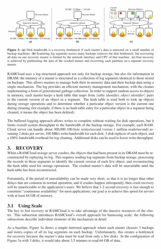
Figure 3: (a) Disk bandwidth is a recovery bottleneck if each master’s data is mirrored on a small number ofbackup machines. (b) Scattering log segments across many backups removes the disk bottleneck, but recoveringall data on one recovery master is limited by the network interface and CPU of that machine. (c) Fast recoveryis achieved by partitioning the data of the crashed master and recovering each partition on a separate recoverymaster.
RAMCloud uses a log-structured approach not only for backup storage, but also for information inDRAM: the memory of a master is structured as a collection of log segments identical to those storedon backups. This allows masters to manage both their in-memory data and their backup data using asingle mechanism. The log provides an efficient memory management mechanism, with the cleanerimplementing a form of generational garbage collection. In order to support random access to objectsin memory, each master keeps a hash table that maps from 〈table identifier, object identifier〉 pairsto the current version of an object in a segment. The hash table is used both to look up objectsduring storage operations and to determine whether a particular object version is the current oneduring cleaning (for example, if there is no hash table entry for a particular object in a segment beingcleaned, it means the object has been deleted).
The buffered logging approach allows writes to complete without waiting for disk operations, but itlimits overall system throughput to the bandwidth of the backup storage. For example, each RAM-Cloud server can handle about 300,000 100-byte writes/second (versus 1 million reads/second) as-suming 2 disks per server, 100 MB/s write bandwidth for each disk, 3 disk replicas of each object, anda 100% bandwidth overhead for log cleaning. Additional disks can be used to boost write throughput.
3. RECOVERYWhen a RAMCloud storage server crashes, the objects that had been present in its DRAM must be re-constructed by replaying its log. This requires reading log segments from backup storage, processingthe records in those segments to identify the current version of each live object, and reconstructingthe hash table used for storage operations. The crashed master’s data will be unavailable until thehash table has been reconstructed.
Fortunately, if the period of unavailability can be made very short, so that it is no longer than otherdelays that are common in normal operation, and if crashes happen infrequently, then crash recoverywill be unnoticeable to the application’s users. We believe that 1-2 second recovery is fast enough toconstitute “continuous availability” for most applications; our goal is to achieve this speed for serverswith at least 64 GB of memory.
3.1 Using ScaleThe key to fast recovery in RAMCloud is to take advantage of the massive resources of the clus-ter. This subsection introduces RAMCloud’s overall approach for harnessing scale; the followingsubsections describe individual elements of the mechanism in detail.
As a baseline, Figure 3a shows a simple mirrored approach where each master chooses 3 backupsand stores copies of all its log segments on each backup. Unfortunately, this creates a bottleneckfor recovery because the master’s data must be read from only a few disks. In the configuration ofFigure 3a with 3 disks, it would take about 3.5 minutes to read 64 GB of data.

RAMCloud works around the disk bottleneck by using more disks during recovery. Each masterscatters its log data across all of the backups in the cluster (each segment on a different set of backups)as shown in Figure 3b. During recovery, these scattered log segments can be read simultaneously;with 1,000 disks, 64 GB of data can be read into memory in less than one second.
Once the segments have been read from disk into backups’ memories, they must be combined to findthe most recent version for each object (no backup can tell in isolation whether a particular object ina particular segment is the most recent version). One approach is to send all the log segments to asingle recovery master and replay the log on that master, as in Figure 3b. Unfortunately, the recoverymaster is a bottleneck in this approach: with a 10 Gbps network interface, it will take about 1 minuteto read 64 GB of data, and the master’s CPU will also be a bottleneck.
To eliminate the recovery master as the bottleneck, RAMCloud uses multiple recovery masters asshown in Figure 3c. During recovery RAMCloud divides the objects of the crashed master intopartitions of roughly equal size. Each partition is assigned to a different recovery master, whichfetches the log data for the partition’s objects from backups and incorporates those objects into itsown log and hash table. With 100 recovery masters operating in parallel, 64 GB of data can betransferred over a 10 Gbps network in less than 1 second. As will be shown in Section 4, this is alsoenough time for each recovery master’s CPU to process the incoming data.
Thus, the overall approach to recovery in RAMCloud is to combine the disk bandwidth, networkbandwidth, and CPU cycles of thousands of backups and hundreds of recovery masters. The sub-sections below describe how RAMCloud divides its work among all of these resources and how itcoordinates the resources to recover in 1-2 seconds.
3.2 Scattering Log SegmentsFor fastest recovery the log segments for each RAMCloud master should be distributed uniformlyacross all of the backups in the cluster. However, there are several factors that complicate this ap-proach:
• Segment placement must reflect failure modes. For example, a segment’s master and each ofits backups must reside in different racks, in order to protect against top-of-rack switch failuresand other problems that disable an entire rack.
• Different backups may have different bandwidth for I/O (different numbers of disks, differentdisk speeds, or different storage classes such as flash memory); segments should be distributedso that each backup uses the same amount of time to read its share of the data during recovery.
• All of the masters are writing segments simultaneously; they should coordinate to avoid over-loading any individual backup. Backups have limited buffer space.
• Storage servers are continuously entering and leaving the cluster, which changes the pool ofavailable backups and may unbalance the distribution of segments.
Making decisions such as segment replica placement in a centralized fashion on the coordinatorwould limit RAMCloud’s scalability. For example, a cluster with 10,000 servers could back up100,000 or more segments per second; this could easily cause the coordinator to become a perfor-mance bottleneck.
Instead, each RAMCloud master decides independently where to place each replica, using a combi-nation of randomization and refinement. When a master needs to select a backup for a segment, itchooses several candidates at random from a list of all backups in the cluster. Then it selects the bestcandidate, using its knowledge of where it has already allocated segment replicas and informationabout the speed of each backup’s disk (backups measure the speed of their disks when they start up

and provide this information to the coordinator, which relays it on to masters). The best backup is theone that can read its share of the master’s segment replicas most quickly from disk during recovery.A backup is rejected if it is in the same rack as the master or any other replica for the current segment.Once a backup has been selected, the master contacts that backup to reserve space for the segment.At this point the backup can reject the request if it is overloaded, in which case the master selectsanother candidate.
The use of randomization eliminates pathological behaviors such as all masters choosing the samebackups in a lock-step fashion. Adding the refinement step provides a solution nearly as optimal asa centralized manager (see [17] and [5] for a theoretical analysis). For example, if a master scatters8,000 segments across 1,000 backups using a purely random approach, backups will have 8 segmentson average. However, some backups are likely to end up with 15-20 segments, which will result inuneven disk utilization during recovery. Adding just a small amount of choice makes the segmentdistribution nearly uniform and also allows for compensation based on other factors such as diskspeed (see Section 4.4). This mechanism also handles the entry of new backups gracefully: a newbackup is likely to be selected more frequently than existing backups until every master has taken fulladvantage of it.
RAMCloud masters mark one of the replicas for each segment as the primary replica. Only theprimary replicas are read during recovery (unless they are unavailable), and the performance opti-mizations described above consider only primary replicas.
We considered the possibility of storing one of the backup replicas on the same machine as themaster. This would reduce network bandwidth requirements, but it has two disadvantages. First, itwould reduce system fault tolerance: the master already has one copy in its memory, so placing asecond copy on the master’s disk provides little benefit. If the master crashes, the disk copy will belost along with the memory copy; it would only provide value in a cold start after a power failure.Second, storing one replica on the master would limit the burst write bandwidth of a master to thebandwidth of its local disks. In contrast, with all replicas scattered, a single master can potentiallyuse the disk bandwidth of the entire cluster (up to the limit of its network interface).
3.3 Failure DetectionRAMCloud detects server failures in two ways. First, RAMCloud clients will notice if a server failsto respond to a remote procedure call. Second, RAMCloud checks its own servers to detect failureseven in the absence of client activity; this allows RAMCloud to replace lost replicas before multiplecrashes cause permanent data loss. Each RAMCloud server periodically issues a ping RPC to anotherserver chosen at random and reports failures to the coordinator. This is another example of using arandomized distributed approach in place of a centralized approach. The probability of detecting acrashed machine in a single round of pings is about 63% for clusters with 100 or more nodes; theodds are greater than 99% that a failed server will be detected within five rounds.
In either case, server failures are reported to the coordinator. The coordinator verifies the problemby attempting to communicate with the server itself, then initiates recovery if the server does notrespond. Timeouts must be relatively short (tens of milliseconds) so that they don’t significantlydelay recovery. See Section 5 for a discussion of the risks introduced by short timeouts.
3.4 Recovery FlowThe coordinator supervises the recovery process, which proceeds in three phases:
1. Setup. The coordinator finds all replicas of all log segments belonging to the crashed master,selects recovery masters, and assigns each recovery master a partition to recover.
2. Replay. Recovery masters fetch log segments in parallel and incorporate the crashed master’spartitions into their own logs.

3. Cleanup. Recovery masters begin serving requests, and the crashed master’s log segments arefreed from backup storage.
These phases are described in more detail below.
3.5 Setup3.5.1 Finding Log Segment Replicas
At the start of recovery, replicas of the crashed master’s segments must be located among the clus-ter’s backups. RAMCloud does not keep a centralized map of replicas since it would be difficult toscale and would hinder common-case performance. Only masters know where their segments arereplicated, but this information is lost when they crash.
The coordinator reconstructs the locations of the crashed master’s replicas by querying all of thebackups in the cluster. Each backup responds with a list of the replicas it has stored for the crashedmaster (backups maintain this index in memory). The coordinator then aggregates the responses intoa single location map. By using RAMCloud’s fast RPC system and querying multiple backups inparallel, the segment location information is collected quickly.
3.5.2 Detecting Incomplete LogsAfter backups return their lists of replicas, the coordinator must determine whether the reportedsegment replicas form the entire log of the crashed master. The redundancy in RAMCloud makesit highly likely that the entire log will be available, but the system must be able to detect situationswhere some data is missing (such as network partitions).
RAMCloud avoids centrally tracking the list of the segments that comprise a master’s log by makingeach log self-describing; the completeness of the log can be verified using data in the log itself. Eachsegment includes a log digest, which is a list of identifiers for all segments in the log at the time thissegment was written. Log digests are small (less than 1% storage overhead even when uncompressed,assuming 8 MB segments and 8,000 segments per master).
This leaves a chance that all the replicas for the newest segment in the log are unavailable, in whichcase the coordinator would not be able to detect that the log is incomplete (the most recent digest itcould find would not list the newest segment). To prevent this, when a master creates a new segmentreplica it makes its transition to the new digest carefully. First, a new digest is inserted in the newreplica, and it is marked as active. Then, after the new active digest is durable, a final update to theprior active digest marks it as inactive. This ordering ensures the log always has an active digest, evenif the master crashes between segments. Two active log digests may be discovered during recovery,but the coordinator simply ignores the newer one since its segment must be empty.
If the active log digest and a replica for each segment cannot be found, then RAMCloud cannotrecover the crashed master. In this unlikely case, RAMCloud notifies the operator and waits forbackups to return to the cluster with replicas for each of the missing segments. Alternatively, at theoperator’s discretion, RAMCloud can continue recovery with loss of data.
3.5.3 Starting Partition RecoveriesNext, the coordinator must divide up the work of recovering the crashed master. The choice ofpartitions for a crashed master is made by the master itself: during normal operation each masteranalyzes its own data and computes a set of partitions that would evenly divide the work of recovery.This information is called a will (it describes how a master’s assets should be divided in the eventof its demise). Masters periodically upload their wills to the coordinator. Section 3.9 describes howmasters compute their wills efficiently.
During recovery setup, the coordinator assigns each of the partitions in the crashed master’s will toan existing master within the cluster. Each of these recovery masters receives two things from the

Recovery MasterBackup
1. Read disk2. Divide segment
data
3. Transfer data
to masters
4. Add objects to
hash table and log
6. Write segment
replicas to disk5. Replicate log
data to backups
Hash table
In-Memory Log
Disk
...
Backup
Disk
...
Figure 4: During recovery, segment data flows from disk or flash on a backup over the network to a recoverymaster, then back to new backups as part of the recovery master’s log.
coordinator: a list of the locations of all the crashed master’s log segments and a list of tablets thatthe recovery master must recover and incorporate into the data it manages.
3.6 ReplayThe vast majority of recovery time is spent replaying segments to reconstruct partitions on the recov-ery masters. During replay the contents of each segment are processed in six stages (see Figure 4):
1. The segment is read from disk into the memory of a backup.
2. The backup divides the records in the segment into separate groups for each partition based ontable and object identifiers in the log records.
3. The records for each partition are transferred over the network to the recovery master for thatpartition.
4. The recovery master incorporates the data into its in-memory log and hash table.
5. As the recovery master fills segments in memory, it replicates those segments over the networkto backups with the same scattering mechanism used in normal operation.
6. The backups write the new segment replicas to disk or flash.
RAMCloud harnesses concurrency in two dimensions during recovery. The first dimension is dataparallelism: different backups read different segments from disk in parallel, different recovery mas-ters reconstruct different partitions in parallel, and so on. The second dimension is pipelining: all ofthe six stages listed above proceed in parallel, with a segment as the basic unit of work. While onesegment is being read from disk on a backup, another segment is being partitioned by that backup’sCPU, and records from another segment are being transferred to a recovery master; similar pipeliningoccurs on recovery masters. For fastest recovery all of the resources of the cluster should be kept fullyutilized, including disks, CPUs, and the network.
3.7 Segment Replay OrderIn order to maximize concurrency, recovery masters and backups operate independently. As soonas the coordinator contacts each backup to obtain its list of segments, the backup begins prefetchingsegments from disk and dividing them by partition. At the same time, masters fetch segment data

from backups and replay it. Ideally backups will constantly run ahead of masters, so that segmentdata is ready and waiting whenever a recovery master requests it. However, this only works if therecovery masters and backups process segments in the same order. If a recovery master accidentallyrequests the last segment in the backup’s order then the master will stall: it will not receive any datato process until the backup has read all of its segments.
In order to avoid pipeline stalls, each backup decides in advance the order in which it will read itssegments. It returns this information to the coordinator during the setup phase, and the coordinatorincludes the order information when it communicates with recovery masters to initiate recovery. Eachrecovery master uses its knowledge of backup disk speeds to estimate when each segment’s data islikely to be loaded. It then requests segment data in order of expected availability. (This approachcauses all masters to request segments in the same order; we could introduce randomization to avoidcontention caused by lock-step behavior.)
Unfortunately, there will still be variations in the speed at which backups read and process segments.In order to avoid stalls because of slow backups, each master keeps several concurrent requests forsegment data outstanding at any given time during recovery; it replays segment data in the order thatthe requests return.
Because of the optimizations described above, recovery masters will end up replaying segments in adifferent order than the one in which the segments were originally written. Fortunately, the versionnumbers in log records allow the log to be replayed in any order without affecting the result. Dur-ing replay each master simply retains the version of each object with the highest version number,discarding any older versions that it encounters.
Although each segment has multiple replicas stored on different backups, only the primary replicasare read during recovery; reading more than one would waste valuable disk bandwidth. Mastersidentify primary replicas when scattering their segments as described in Section 3.2. During recoveryeach backup reports all of its segments, but it identifies the primary replicas and only prefetches theprimary replicas from disk. Recovery masters request non-primary replicas only if there is a failurereading the primary replica.
3.8 CleanupAfter a recovery master completes the recovery of its assigned partition, it notifies the coordinatorthat it is ready to service requests. The coordinator updates its configuration information to indicatethat the master now owns the tablets in the recovered partition, at which point the partition is availablefor client requests. Clients with failed RPCs to the crashed master have been waiting for new config-uration information to appear; they discover it and retry their RPCs with the new master. Recoverymasters can begin service independently without waiting for other recovery masters to finish.
Once all recovery masters have completed recovery, the coordinator contacts each of the backupsagain. At this point the backups free the storage for the crashed master’s segments, since it is nolonger needed. Recovery is complete once all of the backups have been notified.
3.9 Tablet ProfilingEach master is responsible for creating a will, which describes how its objects should be partitionedduring recovery. A partition consists of one or more tablets. The master should balance its partitionsso that they require roughly equal time to recover, and the partitions should be sized based on thedesired recovery time. The master’s storage is not actually partitioned during normal operation as thiswould create unnecessary overheads; partitioning only occurs during recovery. The master uploadsits will to the coordinator and updates the will as its data evolves.
RAMCloud computes wills using tablet profiles. Each tablet profile tracks the distribution of resourceusage within a single table or tablet in a master. It consists of a collection of buckets, each of which

Partition
Not in Partition
Unknown
In Partition
0 2 -164
Bucket Key
Figure 5: A tablet profile consists of a hierarchical collection of bucket arrays; buckets are subdivided dynami-cally when their counts become large. The tree structure creates (bounded) uncertainty when assigning partitionboundaries, since counts in ancestor buckets may represent objects either before or after the boundary.
counts the number of log records corresponding to a range of object identifiers, along with the totallog space consumed by those records. Tablet profiles are updated as new log records are created andold segments are cleaned, and the master periodically scans its tablet profiles to compute a new will.
Unfortunately, it isn’t possible to choose the buckets for a tablet profile statically because the spaceof object identifiers is large (264) and clients can allocate object identifiers however they wish. Withany static choice of buckets, it is possible that all of the objects in a table could end up in a singlebucket, which would provide no information for partitioning. Buckets must be chosen dynamicallyso that the contents of each bucket are small compared to the contents of a partition.
RAMCloud represents a tablet profile as a dynamic tree of bucket arrays, as shown in Figure 5.Initially the tree consists of a single bucket array that divides the entire 64-bit identifier space intobuckets of equal width (in the current implementation there are 256 buckets in each array). Whenevera master creates a new log record it updates the appropriate bucket. If a bucket becomes too large(the number of records or space usage exceeds a threshold) then a child bucket array is created tosubdivide the bucket’s range into smaller buckets. Future log records are profiled in the child bucketarray instead of the parent. However, the counts in the parent bucket remain (RAMCloud does notattempt to redistribute them in the child bucket array since this could require rescanning a largeportion of the log). The master decrements bucket counts when it cleans log segments. Each bucketarray records the position of the log head when that array was created, and the master uses thisinformation during cleaning to decrement the same bucket that was incremented when the record wascreated (thus, over time the counts in non-leaf buckets are likely to become small). Bucket arrays arecollapsed back into their parents when usage drops.
To calculate partitions, a master scans its tablet profiles in a depth-first search, accumulating countsof records and space usage and establishing partition boundaries whenever the counts reach thresholdvalues. For example, one policy might be to assign partitions based on log space usage so that nopartition has more than 600 MB of log data or more than three million objects.
The tablet profile structure creates uncertainty in the actual usage of a partition, as illustrated in Fig-ure 5. If a partition boundary is placed at the beginning of a leaf bucket, it isn’t possible to tellwhether counts in ancestor buckets belong to the new partition or the previous one. Fortunately, theuncertainty is bounded. For example, in the current RAMCloud implementation, there could be upto 7 ancestor buckets, each of which could account for 8 MB of data (the threshold for subdividing abucket), for a worst-case uncertainty of 56 MB for each partition boundary. In order to bound recov-
ery times, RAMCloud pessimistically assumes that unknown counts fall within the current partition.
In the configuration used for RAMCloud, the memory overhead for tablet profiles is 0.6% in theworst case (8 levels of bucket array for 8 MB of data). The parameters of the tablet profile can bechanged to make trade-offs between the storage overhead for profiles and the accuracy of partitionboundaries.
3.10 ConsistencyWe designed RAMCloud to provide a strong form of consistency (linearizability [13], which requiresexactly-once semantics), even across host failures and network partitions. A full discussion of RAM-Cloud’s consistency architecture is beyond the scope of this paper, and the implementation is not yetcomplete; however, it affects crash recovery in two ways. First, a master that is suspected of failure(a sick master) must stop servicing requests before it can be recovered, to ensure that applicationsalways read and write the latest version of each object. Second, when recovering from suspectedcoordinator failures, RAMCloud must ensure that only one coordinator can manipulate and serve thecluster’s configuration at a time.
RAMCloud will disable a sick master’s backup operations when it starts recovery, so the sick masterwill be forced to contact the coordinator to continue servicing writes. The coordinator contacts back-ups at the start of recovery to locate a replica of every segment in the sick master’s log, including theactive segment to which the master may still be writing. Once a backup with a replica of the activesegment has been contacted, it will reject backup operations from the sick master with an indicationthat the master must stop servicing requests until it has contacted the coordinator. Masters will peri-odically check in with their backups, so disabling a master’s backup operations will also stop it fromservicing read requests by the time recovery completes.
Coordinator failures will be handled safely using the ZooKeeper service [14]. The coordinator willuse ZooKeeper to store its configuration information, which consists of a list of active storage serversalong with the tablets they manage. ZooKeeper uses its own replication mechanisms to providea high level of durability and availability for this information. To handle coordinator failures, theactive coordinator and additional standby coordinators will compete for a single coordinator leasein ZooKeeper, which ensures that at most one coordinator runs at a time. If the active coordinatorfails or becomes disconnected, its lease will expire and it will stop servicing requests. An arbitrarystandby coordinator will acquire the lease, read the configuration information from ZooKeeper, andresume service. The configuration information is small, so we expect to recover from coordinatorfailures just as quickly as other server failures.
3.11 Additional Failure ModesOur work on RAMCloud so far has focused on recovering the data stored in the DRAM of a singlefailed master. The sections below describe several other ways in which failures can occur in a RAM-Cloud cluster and some preliminary ideas for dealing with them; we defer a full treatment of thesetopics to future work.
3.11.1 Backup FailuresRAMCloud handles the failure of a backup server by creating new replicas to replace the ones onthe failed backup. Every master is likely to have at least one segment replica on the failed backup,so the coordinator notifies all of the masters in the cluster when it detects a backup failure. Eachmaster checks its segment table to identify segments stored on the failed backup, then it creates newreplicas using the approach described in Section 3.2. All of the masters perform their rereplicationconcurrently and the new replicas are scattered across all of the disks in the cluster, so recovery frombackup failures is fast. If each master has 64 GB of memory then each backup will have about 192GB of data that must be rewritten (assuming 3 replicas for each segment). For comparison, 256 GBof data must be transferred to recover a dead master: 64 GB must be read, then 192 GB must bewritten during rereplication.

CPU Xeon X3470 (4x2.93 GHz cores, 3.6 GHz Turbo)RAM 16 GB DDR3 at 1333 MHzDisk 1 WD 2503ABYX (7200 RPM, 250 GB)
Effective read/write: 105/110 MB/sDisk 2 Seagate ST3500418AS (7200 RPM, 500 GB)
Effective read/write: 108/87 MB/sFlash Crucial M4 CT128M4SSD2 (128GB)Disks Effective read/write: 269/182 MB/sNIC Mellanox ConnectX-2 Infiniband HCA
Switches 5x 36-port Mellanox InfiniScale IV (4X QDR)
Table 1: Experimental cluster configuration. All 60 nodes have identical hardware. Effective disk bandwidth isthe average throughput from 1,000 8 MB sequential accesses to random locations in the first 72 GB of the disk.Flash drives were used in place of disks for Figure 9 only. The cluster has 5 network switches arranged in twolayers. Each port’s maximum network bandwidth is 32 Gbps, but nodes are limited to about 25 Gbps by PCIExpress. The switching fabric is oversubscribed, providing at best about 22 Gbps of bisection bandwidth per nodewhen congested.
3.11.2 Multiple FailuresGiven the large number of servers in a RAMCloud cluster, there will be times when multiple serversfail simultaneously. When this happens, RAMCloud recovers from each failure independently. Theonly difference in recovery is that some of the primary replicas for each failed server may have beenstored on the other failed servers. In this case the recovery masters will use secondary replicas;recovery will complete as long as there is at least one replica available for each segment. It shouldbe possible to recover multiple failures concurrently; for example, if a RAMCloud cluster contains5,000 servers with flash drives for backup, the measurements in Section 4 indicate that a rack failurethat disables 40 masters, each with 64 GB storage, could be recovered in about 2 seconds.
If many servers fail simultaneously, such as in a power failure that disables many racks, RAMCloudmay not be able to recover immediately. This problem arises if no replicas are available for a lostsegment or if the remaining masters do not have enough spare capacity to take over for all the lostmasters. In this case RAMCloud must wait until enough machines have rebooted to provide thenecessary data and capacity (alternatively, an operator can request that the system continue withsome loss of data). RAMCloud clusters should be configured with enough redundancy and sparecapacity to make situations like this rare.
3.11.3 Cold StartRAMCloud must guarantee the durability of its data even if the entire cluster loses power at once.In this case the cluster will need to perform a “cold start” when power returns. Normally, when abackup restarts, it discards all of the segments stored on its disk or flash, since they have alreadybeen rereplicated elsewhere. However, in a cold start this information must be preserved. Backupswill contact the coordinator as they reboot, and the coordinator will instruct them to retain existingdata; it will also retrieve a list of their segments. Once a quorum of backups has become available,the coordinator will begin reconstructing masters. RAMCloud can use the same partitioned approachdescribed above, but it may make more sense to use a different approach where masters are recon-structed exactly as they existed before the cold start. This will be faster than the partitioned approachbecause masters will not need to write any backup data: the existing backups can continue to serveafter the masters are reconstructed.
The current RAMCloud implementation does not perform cold starts.
4. EVALUATIONWe implemented the RAMCloud architecture described in Sections 2 and 3, and we evaluated theperformance and scalability of crash recovery using a 60-node cluster. The cluster hardware consistsof standard off-the-shelf components (see Table 1) with the exception of its networking equipment,which is based on Infiniband; with it our end hosts achieve both high bandwidth (25 Gbps) and low

0
500
1000
1500
2000
2500
0 200 400 600 800 1000
Re
co
ve
ry T
ime
(m
s)
Partition Size (MB)
128 B objects256 B objects1 KB objects
Figure 6: Recovery time as a function of partition size with a single recovery master and 60 backups. Each curveuses objects of a single uniform size.
latency (user-level applications can communicate directly with the NICs to send and receive packets,bypassing the kernel).
The default experimental configuration used one backup server on each machine, with a single disk.A subset of these machines also ran recovery masters. One additional machine ran the coordinator,the crashed master, and the client application. In order to increase the effective scale of the system,some experiments ran two independent backup servers on each machine (each with one disk).
In each experiment a client application observed and measured a crash of a single master and thesubsequent recovery. The client initially filled the master with objects of a single size (1,024 bytesby default). It then sent a magic RPC to the coordinator which caused it to recover the master. Theclient waited until all partitions had been successfully recovered, then read a value from one of thosepartitions and reported the end-to-end recovery time. All experiments used a disk replication factorof 3 (i.e., 3 replicas on disk in addition to one copy in DRAM). The CPUs, disks, and networks wereidle and entirely dedicated to recovery (in practice, recovery would have to compete for resourceswith application workloads, though we would argue for giving priority to recovery).
Each of the subsections below addresses one question related to the performance of recovery. Theoverall results are:
• A 60-node cluster can recover lost data at about 22 GB/sec (a crashed server with 35 GB storagecan be recovered in 1.6 seconds), and recovery performance scales with cluster size. However,our scalability measurements are limited by the small size of our test cluster.
• The speed of an individual recovery master is limited primarily by network speed for writingnew segment replicas.
• The segment scattering algorithm distributes segments effectively and compensates for varyingdisk speeds.
• Fast recovery significantly reduces the risk of data loss.
4.1 How Large Should Partitions Be?Our first measurements provide data for configuring RAMCloud (partition size and number of disksneeded per recovery master). Figure 6 measures how quickly a single recovery master can process

0
200
400
600
800
1000
1200
1400
1600
1800
0 2 4 6 8 10 12 14 16 18
Re
co
ve
ry T
ime
(m
s)
Number of Backups (Disks)
Total RecoveryMax. Disk ReadingAvg. Disk Reading
Figure 7: Recovery time as a function of the number of disks, with a single recovery master, one 600 MB partitionwith 1,024 byte objects, and each disk on a separate machine. “Avg. Disk Reading” measures the average elapsedtime (across all disks) to read backup data during recovery; “Max. Disk Reading” graphs the longest time for anydisk in the cluster. Once 6-8 disks are available recovery time is limited by the network of the recovery master.
backup data, assuming enough backups to keep the recovery master fully occupied. Depending on theobject size, a recovery master can replay log data at a rate of 400-800 MB/s, including the overheadfor reading the data from backups and writing new backup copies. With small objects the speedof recovery is limited by the cost of updating the hash table and tablet profiles. With large objectsrecovery is limited by the network speed during writes to new backups (for example, with 600 MBpartitions and a disk replication factor of 3, the recovery master must write 1.8 GB of data to backups).
For 1-second recovery Figure 6 suggests that partitions should be limited to no more than 800 MBand no more than 3 million log records (with 128-byte objects a recovery master can process 400 MBof data per second, which is roughly 3 million log records). With 10 Gbps Ethernet, partitions mustbe limited to 300 MB due to the bandwidth requirements for rereplication.
In our measurements we filled the log with live objects, but the presence of deleted versions will,if anything, make recovery faster. The master’s memory has the same log structure as the backupreplicas, so the amount of log data to read will always be equal to the size of the master’s memory,regardless of deleted versions. However, deleted versions may not need to be rereplicated (dependingon the order of replay).
4.2 How Many Disks Are Needed for Each Recovery Master?Each of our disks provided an effective bandwidth of 100-110 MB/s when reading 8 MB segments;combined with Figure 6, this suggests that RAMCloud will need about 6-8 disks for each recoverymaster in order to keep the pipeline full. Figure 7 graphs recovery performance with one recoverymaster and a varying number of disks and reaches the same conclusion. With large numbers of disks,the speed of recovery is limited by outbound network bandwidth on the recovery master.
4.3 How Well Does Recovery Scale?The most important issue in recovery for RAMCloud is scalability: if one recovery master can recover600 MB of data in one second, can 10 recovery masters recover 6 GB in the same time, and can 100recovery masters recover 60 GB? Unfortunately, the disk bandwidth available in our cluster limited usto 20 recovery masters (120 backups), which is only about 20% the number we would expect in a full-size RAMCloud recovery. Nonetheless, within this limited range RAMCloud demonstrates excellentscalability. Figure 8 graphs recovery time as the amount of lost data is increased and the cluster size isincreased to match. For each 600 MB partition of lost data, the cluster includes one recovery master

0
200
400
600
800
1000
1200
1400
1600
1800
0 5 10 15 20
Re
co
ve
ry T
ime
(m
s)
Number of 600 MB Partitions(Recovery Masters)
Total RecoveryMax. Disk ReadingAvg. Disk Reading
Figure 8: Recovery performance under proportional scaling (one recovery master and 6 backups for each 600 MBpartition of data to recover). Each recovery master shared a host with 2 backups, and each point is an average of 5runs (Figure 11 shows the variance between runs). A horizontal line would indicate perfect scalability. Recoverytime is limited by disk bandwidth.
and 6 backups with one disk each. With 20 recovery masters and 120 disks, RAMCloud can recover11.7 GB of data in under 1.1 seconds, which is only 13% longer than it takes to recover 600 MB witha single master and 6 disks.
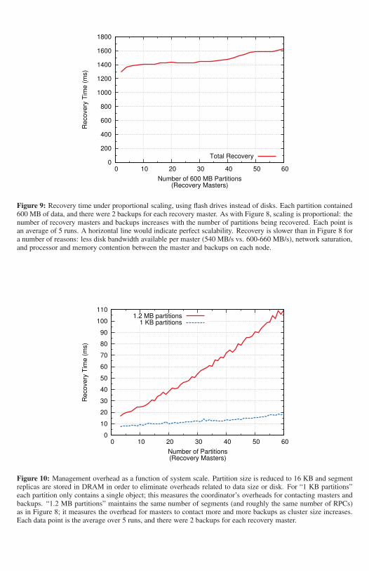
In order to allow more recovery masters to participate in recovery, we replaced all the disks in ourcluster with flash drives, each of which provided 270 MB/s read bandwidth (as opposed to 110 MB/sfor the disks). With this configuration we were able to run recoveries that used 60 recovery masters,as shown in Figure 9. The system still scales well: with 60 recovery masters RAMCloud can recover35 GB of data from a lost server in about 1.6 seconds, which is 26% longer than it takes 2 recoverymasters to recover 1.2 GB of data.
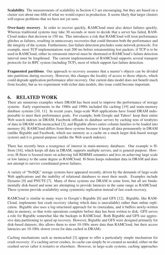
It is important to keep the overhead for additional masters and backups small, so that recovery canspan hundreds of hosts in large clusters. In order to isolate these overheads, we ran additional exper-iments with artificially small segments (16 KB) and kept all segment replicas in DRAM to eliminatedisk overheads. Figure 10 (bottom curve) shows the recovery time using trivial partitions containingjust a single 1 KB object; this measures the cost for the coordinator to contact all the backups andmasters during the setup phase. Our cluster scales to 60 recovery masters with only about a 10 msincrease in recovery time (thanks in large part to fast RPCs).
Figure 10 also shows recovery time using 1.2 MB partitions and 16 KB segments (upper curve). Inthis configuration the cluster performs roughly the same number of RPCs as it does in Figure 8, but ithas very little data to process. This exposes the fixed overheads for recovery masters to communicatewith backups: as the system scale increases, each master must contact more backups, retrievingless data from each individual backup. Each additional recovery master adds only about 1.5 ms ofoverhead, so work can be split across 100 recovery masters without substantially increasing recoverytime.
4.4 How Well Does Segment Scattering Work?Figure 11 shows that the segment placement algorithm described in Section 3.2 works well. Wemeasured three different variations of the placement algorithm: the full algorithm, which considersboth disk speed and number of segments already present on each backup; a version that uses purelyrandom placement; and an in-between version that attempts to even out the number of segmentson each backup but does not consider disk speed. The top graph in Figure 11 shows that the full
0
200
400
600
800
1000
1200
1400
1600
1800
0 10 20 30 40 50 60
Re
co
ve
ry T
ime
(m
s)
Number of 600 MB Partitions(Recovery Masters)
Total Recovery
Figure 9: Recovery time under proportional scaling, using flash drives instead of disks. Each partition contained600 MB of data, and there were 2 backups for each recovery master. As with Figure 8, scaling is proportional: thenumber of recovery masters and backups increases with the number of partitions being recovered. Each point isan average of 5 runs. A horizontal line would indicate perfect scalability. Recovery is slower than in Figure 8 fora number of reasons: less disk bandwidth available per master (540 MB/s vs. 600-660 MB/s), network saturation,and processor and memory contention between the master and backups on each node.
0
10
20
30
40
50
60
70
80
90
100
110
0 10 20 30 40 50 60
Recovery
Tim
e (
ms)
Number of Partitions(Recovery Masters)
1.2 MB partitions1 KB partitions
Figure 10: Management overhead as a function of system scale. Partition size is reduced to 16 KB and segmentreplicas are stored in DRAM in order to eliminate overheads related to data size or disk. For “1 KB partitions”each partition only contains a single object; this measures the coordinator’s overheads for contacting masters andbackups. “1.2 MB partitions” maintains the same number of segments (and roughly the same number of RPCs)as in Figure 8; it measures the overhead for masters to contact more and more backups as cluster size increases.Each data point is the average over 5 runs, and there were 2 backups for each recovery master.

0%
25%
50%
75%
100%
Cu
mu
lative
Pe
rce
nt
Fans Normal
Even Read TimeEven Segments
Uniform Random
0%
25%
50%
75%
100%
0 1 2 3 4 5 6 7 8
Cu
mu
lative
Pe
rce
nt
Recovery Time (seconds)
Fans High
Figure 11: Impact of segment placement on recovery time. Each line is a cumulative distribution of 120 recoveriesof twenty 600 MB partitions, showing the percent of recoveries that completed within a given time. “Even ReadTime” uses the placement algorithm described in Section 3.2; “Uniform Random” uses a purely random approach;and “Even Segments” attempts to spread segments evenly across backups without considering disk speed. The topgraph measured the cluster in its normal configuration, with relatively uniform disk performance; the bottom graphmeasured the system as it was shipped (unnecessarily high fan speed caused vibrations that degraded performancesignificantly for some disks). With fans at normal speed, “Even Read Time” and “Even Segments” perform nearlythe same since there is little variation in disk speed.
algorithm improves recovery time by about 33% over a purely random placement mechanism. Muchof the improvement came from evening out the number of segments on each backup; consideringdisk speed improves recovery time by only 12% over the even-segment approach because the disksdid not vary much in speed.
To further test how the algorithm handles variations in disk speed, we also took measurements usingthe configuration of our cluster when it first arrived. The fans were shipped in a “max speed” debug-ging setting, and the resulting vibration caused large variations in speed among the disks (as much asa factor of 4x). In this environment the full algorithm provided an even larger benefit over purely ran-dom placement, but there was relatively little benefit from considering segment counts without alsoconsidering disk speed (Figure 11, bottom graph). RAMCloud’s placement algorithm compensateseffectively for variations in the speed of disks, allowing recovery times almost as fast with highlyvariable disks as with uniform disks. Disk speed variations may not be significant in our currentcluster, but we think they will be important in large datacenters where there are likely to be differentgenerations of hardware.
4.5 Will Scattering Result in Data Loss?RAMCloud’s approach of scattering segment replicas allows faster recovery, but it increases the sys-tem’s vulnerability in the event of simultaneous node failures. For example, consider a cluster with1,000 nodes and 2x disk replication. With RAMCloud’s scattering approach to segment placement,there is a 5% chance that data will be lost if any 3 nodes fail simultaneously (the three nodes willaccount for the master and both backups for at least one segment). In contrast, if each master con-centrates all its segment replicas on two backups, as in Figure 3a, the probability of data loss dropsto less than 10-5 with 3 simultaneous failures.
Fortunately, the fast recovery enabled by scattering makes it unlikely that a second or third failurewill occur before a first failure has been recovered, and this more than makes up for the additionalvulnerability, as shown in Figure 12. With one-second recovery the probability of data loss is verylow (about 10-5 in one year even with a 100,000-node cluster). The risk of data loss rises rapidlywith recovery time: if recovery takes 1,000 seconds, then RAMCloud is likely to lose data in anyone-year period. The line labeled “100s” corresponds roughly to the recovery mechanisms in othersystems such as GFS and HDFS (these systems keep 3 replicas on disk, vs. 1 replica in DRAM and 2

1e-09
1e-08
1e-07
1e-06
1e-05
0.0001
0.001
0.01
0.1
1
100 1000 10000 100000
Pro
ba
bili
ty o
f D
ata
Lo
ss in
On
e Y
ea
r
Number of Servers
1000s100s10s1s
Concentrated 100sConcentrated 10s
Figure 12: Probability of data loss in one year as a function of cluster size, assuming 8,000 segments per master,two disk replicas for each DRAM copy, and two crashes per year per server with a Poisson arrival distribution.Different lines represent different recovery times. Lines labeled “Concentrated” assume that segments are con-centrated instead of scattered: each master picks 2 backups at random and replicates all of its segments on eachof those backups.
replicas on disk for the corresponding RAMCloud); with large cluster sizes these other systems maybe vulnerable to data loss. Using a concentrated approach rather than scattering improves reliability,but the benefit from faster recovery is much larger: a 10x improvement in recovery time improvesreliability more than a 1,000x reduction in scattering.
One risk with Figure 12 is that it assumes server failures are independent. There is considerableevidence that this is not the case in datacenters [23, 8]; for example, it is not unusual for entire racksto become inaccessible at once. Thus it is important for the segment scattering algorithm to considersources of correlated failure, such as rack boundaries. If there are unpredictable sources of correlatedfailure, they will result in longer periods of unavailability while RAMCloud waits for one or more ofthe backups to reboot (RAMCloud is no better or worse than other systems in this respect).
Although we made all of the performance measurements in this section with 3x disk replication to beconservative, Figure 12 suggests that the combination of two copies on disk and one copy in DRAMshould be quite safe. The main argument for 3x disk replication is to ensure 3-way redundancy evenin the event of a datacenter power outage, which would eliminate the DRAM copies. With 3x diskreplication in addition to the DRAM copy, the likelihood of data loss is extremely small: less than1% in a year even with 100,000 servers and 1,000-second recovery times.
4.6 What Is the Fastest Possible Recovery?Assuming that recovery is scalable, it should be possible to recover even faster than 1-2 seconds byusing more backups and more recovery masters, with smaller partitions. However, we think that itwill be difficult to recover faster than a few hundred milliseconds without significant changes to therecovery mechanism. For example, RAMCloud currently requires 150 milliseconds just to detectfailure, and the time for the coordinator to contact every backup may approach 100 ms in a largecluster. In addition, it takes nearly 100 ms to read a single segment from disk (but this could bereduced if flash memory replaces disk for backup storage).
5. RISKSThere are three risks associated with RAMCloud’s recovery mechanism that we have not been ableto fully evaluate yet. We hope to learn more about these risks (and devise solutions, if necessary) aswe gain more experience with the system.
Scalability. The measurements of scalability in Section 4.3 are encouraging, but they are based on acluster size about one-fifth of what we would expect in production. It seems likely that larger clusterswill expose problems that we have not yet seen.
Over-hasty recovery. In order to recover quickly, RAMCloud must also detect failures quickly.Whereas traditional systems may take 30 seconds or more to decide that a server has failed, RAM-Cloud makes that decision in 150 ms. This introduces a risk that RAMCloud will treat performanceglitches as failures, resulting in unnecessary recoveries that could threaten both the performance andthe integrity of the system. Furthermore, fast failure detection precludes some network protocols. Forexample, most TCP implementations wait 200 ms before retransmitting lost packets; if TCP is to beused in RAMCloud, either its retransmit interval must be shortened or RAMCloud’s failure detectioninterval must be lengthened. The current implementation of RAMCloud supports several transportprotocols for its RPC system (including TCP), most of which support fast failure detection.
Fragmented partitions. Our approach to recovery assumes that a master’s objects can be dividedinto partitions during recovery. However, this changes the locality of access to those objects, whichcould degrade application performance after recovery. Our current data model does not benefit muchfrom locality, but as we experiment with richer data models, this issue could become important.
6. RELATED WORKThere are numerous examples where DRAM has been used to improve the performance of storagesystems. Early experiments in the 1980s and 1990s included file caching [19] and main-memorydatabase systems [10, 11]. In recent years, large-scale Web applications have found DRAM indis-pensable to meet their performance goals. For example, both Google and Yahoo! keep their entireWeb search indexes in DRAM; Facebook offloads its database servers by caching tens of terabytesof data in DRAM with memcached [3]; and Bigtable allows entire column families to be loaded intomemory [6]. RAMCloud differs from these systems because it keeps all data permanently in DRAM(unlike Bigtable and Facebook, which use memory as a cache on a much larger disk-based storagesystem) and it is general-purpose (unlike the Web search indexes).
There has recently been a resurgence of interest in main-memory databases. One example is H-Store [16], which keeps all data in DRAM, supports multiple servers, and is general-purpose. How-ever, H-Store is focused more on achieving full RDBMS semantics and less on achieving large scaleor low latency to the same degree as RAMCloud. H-Store keeps redundant data in DRAM and doesnot attempt to survive coordinated power failures.
A variety of “NoSQL” storage systems have appeared recently, driven by the demands of large-scaleWeb applications and the inability of relational databases to meet their needs. Examples includeDynamo [9] and PNUTS [7]. Many of these systems use DRAM in some form, but all are funda-mentally disk-based and none are attempting to provide latencies in the same range as RAMCloud.These systems provide availability using symmetric replication instead of fast crash recovery.
RAMCloud is similar in many ways to Google’s Bigtable [6] and GFS [12]. Bigtable, like RAM-Cloud, implements fast crash recovery (during which data is unavailable) rather than online repli-cation. Bigtable also uses a log-structured approach for its (meta)data, and it buffers newly-writtendata in memory, so that write operations complete before data has been written to disk. GFS servesa role for Bigtable somewhat like the backups in RAMCloud. Both Bigtable and GFS use aggres-sive data partitioning to speed up recovery. However, Bigtable and GFS were designed primarily fordisk-based datasets; this allows them to store 10-100x more data than RAMCloud, but their accesslatencies are 10-100x slower (even for data cached in DRAM).
Caching mechanisms such as memcached [3] appear to offer a particularly simple mechanism forcrash recovery: if a caching server crashes, its cache can simply be re-created as needed, either on thecrashed server (after it restarts) or elsewhere. However, in large-scale systems, caching approaches
can cause large gaps in availability after crashes. Typically these systems depend on high cache hitrates to meet their performance requirements; if caches are flushed, the system may perform so poorlythat it is essentially unusable until the cache has refilled. This happened in an outage at Facebook inSeptember 2010 [1]: a software error caused 28 TB of memcached data to be flushed, rendering thesite unusable for 2.5 hours while the caches refilled from slower database servers.
Randomization has been used by several previous systems to allow system management decisions tobe made in a distributed and scalable fashion. For example, consistent hashing uses randomizationto distribute objects among a group of servers [24, 9]. Mitzenmacher and others have studied thetheoretical properties of randomization with refinement and have shown that it produces near-optimalresults [17, 5].
RAMCloud’s log-structured approach to storage management is similar in many ways to log-structuredfile systems (LFS) [21]. However, log management in RAMCloud is simpler and more efficient thanin LFS. RAMCloud is simpler because the log need not contain metadata to enable random-accessreads as in LFS: the hash table enables fast access to data in DRAM, and the disk log is never readexcept during recovery, at which time the entire log is read. Thus the log consists primarily of objectrecords and tombstones that mark their deletion. RAMCloud does not require checkpoints as in LFS,because it replays the entire log during recovery. RAMCloud is more efficient than LFS because itneed not read data from disk during cleaning: all live data is always in memory. The only I/O duringcleaning is to rewrite live data at the head of the log; as a result, RAMCloud consumes 3-10x lessbandwidth for cleaning than LFS (cleaning cost has been a controversial topic for LFS; see [22], forexample).
7. CONCLUSIONIn this paper we have demonstrated that the resources of a large-scale storage system can be used torecover quickly from server crashes. RAMCloud distributes backup data across a large number ofsecondary storage devices and employs both data parallelism and pipelining to achieve end-to-endrecovery times of 1-2 seconds. Although we have only been able to evaluate RAMCloud on a smallcluster, our measurements indicate that the techniques will scale to larger clusters. Our implementa-tion uses a simple log-structured representation for data, both in memory and on secondary storage,which provides high write throughput in addition to enabling fast recovery.
Fast crash recovery is a key enabler for RAMCloud: it allows a high-performance DRAM-basedstorage system to provide durability and availability at one-third the cost of a traditional approachusing online replicas.
8. ACKNOWLEDGMENTSAsaf Cidon reeducated us on the fundamentals of probability and assisted us with several calculations,including Figure 12. Nanda Kumar Jayakumar helped us with performance measurements and someof the figures in the paper. Several people provided helpful feedback on the paper, including AsafCidon, Ankita Kejriwal, Kay Ousterhout, George Varghese, the anonymous SOSP reviewers, and ourshepherd Geoff Voelker. This work was supported by the Gigascale Systems Research Center and theMultiscale Systems Center, two of six research centers funded under the Focus Center Research Pro-gram, a Semiconductor Research Corporation program, and by Facebook, Mellanox, NEC, NetApp,SAP, and Samsung. This work was also partially supported by NSF Cybertrust awards CNS-0716806and CNS-1052985 (CT-T: A Clean-Slate Infrastructure for Information Flow Control). Diego Ongarois supported by The Junglee Corporation Stanford Graduate Fellowship. Steve Rumble is supportedby a Natural Sciences and Engineering Research Council of Canada Postgraduate Scholarship.
9. REFERENCES[1] More Details on Today’s Outage | Facebook, Sept. 2010.
http://www.facebook.com/note.php?note_id=431441338919.[2] Agiga tech agigaram, Mar. 2011. http://www.agigatech.com/agigaram.php.
[3] memcached: a distributed memory object caching system, Jan. 2011.http://www.memcached.org/.
[4] M. K. Aguilera, A. Merchant, M. Shah, A. Veitch, and C. Karamanolis. Sinfonia: A newparadigm for building scalable distributed systems. ACM Trans. Comput. Syst., 27:5:1–5:48,November 2009.
[5] Y. Azar, A. Z. Broder, A. R. Karlin, and E. Upfal. Balanced allocations (extended abstract). InProceedings of the twenty-sixth annual ACM symposium on theory of computing, STOC ’94,pages 593–602, New York, NY, USA, 1994. ACM.
[6] F. Chang, J. Dean, S. Ghemawat, W. C. Hsieh, D. A. Wallach, M. Burrows, T. Chandra,A. Fikes, and R. E. Gruber. Bigtable: A distributed storage system for structured data. ACMTrans. Comput. Syst., 26:4:1–4:26, June 2008.
[7] B. F. Cooper, R. Ramakrishnan, U. Srivastava, A. Silberstein, P. Bohannon, H.-A. Jacobsen,N. Puz, D. Weaver, and R. Yerneni. Pnuts: Yahoo!’s hosted data serving platform. Proc. VLDBEndow., 1:1277–1288, August 2008.
[8] J. Dean. Keynote talk: Evolution and future directions of large-scale storage and computationsystems at google. In Proceedings of the 1st ACM symposium on Cloud computing, Jun 2010.
[9] G. DeCandia, D. Hastorun, M. Jampani, G. Kakulapati, A. Lakshman, A. Pilchin,S. Sivasubramanian, P. Vosshall, and W. Vogels. Dynamo: amazon’s highly available key-valuestore. In Proceedings of twenty-first ACM SIGOPS symposium on operating systems principles,SOSP ’07, pages 205–220, New York, NY, USA, 2007. ACM.
[10] D. J. DeWitt, R. H. Katz, F. Olken, L. D. Shapiro, M. R. Stonebraker, and D. A. Wood.Implementation techniques for main memory database systems. In Proceedings of the 1984ACM SIGMOD international conference on management of data, SIGMOD ’84, pages 1–8,New York, NY, USA, 1984. ACM.
[11] H. Garcia-Molina and K. Salem. Main memory database systems: An overview. IEEE Trans.on Knowl. and Data Eng., 4:509–516, December 1992.
[12] S. Ghemawat, H. Gobioff, and S.-T. Leung. The google file system. In Proceedings of thenineteenth ACM symposium on Operating systems principles, SOSP ’03, pages 29–43, NewYork, NY, USA, 2003. ACM.
[13] M. P. Herlihy and J. M. Wing. Linearizability: a correctness condition for concurrent objects.ACM Trans. Program. Lang. Syst., 12:463–492, July 1990.
[14] P. Hunt, M. Konar, F. P. Junqueira, and B. Reed. Zookeeper: wait-free coordination forinternet-scale systems. In Proceedings of the 2010 USENIX annual technical conference,USENIX ATC ’10, pages 11–11, Berkeley, CA, USA, 2010. USENIX Association.
[15] R. Johnson and J. Rothschild. Personal Communications, March 24 and August 20, 2009.[16] R. Kallman, H. Kimura, J. Natkins, A. Pavlo, A. Rasin, S. Zdonik, E. P. C. Jones, S. Madden,
M. Stonebraker, Y. Zhang, J. Hugg, and D. J. Abadi. H-store: a high-performance, distributedmain memory transaction processing system. Proc. VLDB Endow., 1:1496–1499, August 2008.
[17] M. D. Mitzenmacher. The power of two choices in randomized load balancing. PhD thesis,University of California, Berkeley, 1996. AAI9723118.
[18] J. Ousterhout, P. Agrawal, D. Erickson, C. Kozyrakis, J. Leverich, D. Mazières, S. Mitra,A. Narayanan, D. Ongaro, G. Parulkar, M. Rosenblum, S. M. Rumble, E. Stratmann, andR. Stutsman. The case for ramcloud. Commun. ACM, 54:121–130, July 2011.
[19] J. K. Ousterhout, A. R. Cherenson, F. Douglis, M. N. Nelson, and B. B. Welch. The spritenetwork operating system. Computer, 21:23–36, February 1988.
[20] D. A. Patterson, G. Gibson, and R. H. Katz. A case for redundant arrays of inexpensive disks(raid). In Proceedings of the 1988 ACM SIGMOD international conference on management ofdata, SIGMOD ’88, pages 109–116, New York, NY, USA, 1988. ACM.
[21] M. Rosenblum and J. K. Ousterhout. The design and implementation of a log-structured filesystem. ACM Trans. Comput. Syst., 10:26–52, February 1992.
[22] M. Seltzer, K. A. Smith, H. Balakrishnan, J. Chang, S. McMains, and V. Padmanabhan. Filesystem logging versus clustering: a performance comparison. In Proceedings of the USENIX1995 Technical Conference, TCON’95, pages 21–21, Berkeley, CA, USA, 1995. USENIX

Association.[23] K. Shvachko, H. Kuang, S. Radia, and R. Chansler. The hadoop distributed file system. In
Proceedings of the 2010 IEEE 26th Symposium on Mass Storage Systems and Technologies(MSST), MSST ’10, pages 1–10, Washington, DC, USA, 2010. IEEE Computer Society.
[24] I. Stoica, R. Morris, D. Liben-Nowell, D. R. Karger, M. F. Kaashoek, F. Dabek, andH. Balakrishnan. Chord: a scalable peer-to-peer lookup protocol for internet applications.IEEE/ACM Trans. Netw., 11:17–32, February 2003.