fast electrical switching of orbital angular … · fast electrical switching of orbital angular...
TRANSCRIPT
1
Fast Electrical Switching of Orbital Angular Momentum
Modes Using Ultra-compact Integrated Vortex Emitters
Michael J. Strain*,1,2, Xinlun Cai*,3,4 , Jianwei Wang*,4, Jiangbo Zhu3,5, David B. Phillips6,
Lifeng Chen5, Martin Lopez-Garcia5, Jeremy L. O’Brien4, Mark G. Thompson4, Marc Sorel2,
and Siyuan Yu3,5
1Institute of Photonics, University of Strathclyde, Wolfson Centre, 106 Rottenrow East,
Glasgow G4 0NW, UK.
2School of Engineering, Rankine Building, Oakfield Avenue, University of Glasgow, Glasgow
G12 8LT, UK.
3 State Key Laboratory of Optoelectronic Materials and Technologies and School of Physics
and Engineering, Sun Yatsen University, Guangzhou, China.
4Centre for Quantum Photonics, H. H. Wills Physics Laboratory and Department of
Electrical and Electronic Engineering, University of Bristol, Bristol BS8 1UB, UK.
5Photonics Research Group, Merchant Venturers School of Engineering, University of Bristol,
Woodland Road, Bristol BS8 1UB, UK.
6SUPA, School of Physics and Astronomy, University of Glasgow, Glasgow, G12 8QQ, UK.
* These authors contributed equally to this work.
The ability to rapidly switch between orbital angular momentum modes of
light has important implications for future classical and quantum systems.
In general, orbital angular momentum beams are generated using
free-space bulk optical components where the fastest reconfiguration of
such systems is around a millisecond using spatial light modulators. In this
work, an extremely compact optical vortex emitter is demonstrated with
the ability to actively tune between different orbital angular momentum
modes. The emitter is tuned using a single electrically contacted
thermo-optical control, maintaining device simplicity and micron scale
footprint. On-off keying and orbital angular momentum mode switching
are achieved at rates of 10 μs and 20 μs respectively.
2
The orbital angular momentum (OAM) of light represents an additional degree of
freedom for light beams and single photons over those used in conventional
optical systems (i.e. polarization and wavelength)1, 2. OAM is defined in an
unbounded infinite-dimensional space, therefore it is possible to encode a much
larger amount of information in this degree of freedom, offering orders of
magnitude greater transmission capacity3-6, as well as allowing for
higher-security communication protocols7-10. This makes OAM very attractive for
applications in future optical communication and quantum key distribution
(QKD) systems.
To fully access the benefits of the OAM degree of freedom, devices that can
rapidly switch between OAM modes are highly desirable. For classical
communication systems, multiplexing and demultiplexing of OAM modes has
recently led to record-breaking data communication rates both in free space3 and
in optical fibres4. In a similar manner to the evolution of
wavelength-division-multiplexed (WDM) systems, the future advancement of
OAM-based telecommunications systems will require OAM routing flexibility and
reconfigurability with components that can perform the fast switching of OAM
data channels5, 11. For quantum communication systems, current QKD schemes,
relying on polarization encoding, suffer a tight bound on the error tolerance due
to the limits on the amount of information that can be sent per photon8,9.
OAM-based QKD systems show the promise of providing an enhanced tolerance
to errors, and therefore the potential for a quantum communication channel that
is more robust against eavesdropping7-10. The development of fast OAM
switching devices is of great importance for OAM-based QKD systems, because
the key generation rate of the systems is currently limited by the switching speed
of OAM states in such devices.
The commonly used OAM switching or manipulation tools, including spatial
light modulators (SLMs)12, 13 and q-plates14, 15 are slow to respond with the best
switching rates of the order of 1 kHz. Higher switching rates have been reported
by using digital micro-mirror devices (DMD)16, combining q-plates with
electro-optical modulators, or combining SLMs with acousto-optic modulators17.

3
However, all of these approaches rely on large scale optical components with
limitations in terms of cost, stability and scalability. Recently, several integrated
photonic circuits have been demonstrated for the generation and measurement
of OAM carrying beams18-20. These circuits rely on complicated phase-sensitive
arrayed waveguide structures with a large number of electrical contacts for
phase calibration.
Here, based on our previous work21, we report an ultra-compact tunable
integrated OAM device on silicon-on-isolator material, capable of actively on-off
keying OAM modes at record rates of 10 μs and switching OAM modes at record
rates of 20 μs. A single electrically contacted thermo-optical control is used to
achieve rapid switching of OAM modes. Additionally, the emitted OAM modes
show high mode purities within the range of 86% to 99%. This work paves the
way for a scalable integrated silicon photonic platform for high-speed switching
of the OAM modes of light on-chip.
Results
Principle. We have previously presented an integrated device for the emission of
optical beams with well-defined OAM modes21. The operation principle of the
device is based on the coupling of whispering gallery modes (WGM) of a
micro-resonator to free-space propagating OAM modes through the use of an
angular grating (AG) embedded within the micro-resonator. The generated OAM
mode order, l, is defined by the resonant WGM order, p, and the number of
scattering elements in the ring, q, as:
l=p−q (1)
This device benefits from extremely simple operation and compact size,
requiring only a ring resonator and a bus waveguide for coupling of the input
optical signal. Different OAM modes can then be addressed by aligning the input
wavelength to different resonances of the device. In this paper a complimentary
method by which the emitted OAM modes at a fixed wavelength can be actively
modulated is presented, using only a single electrical component.
The resonant WGM wavelengths, R, of a ring resonator can be defined as:
4
λR=
ne
Lc
p, (2)
where ne is the wavelength dependent effective index of the waveguide and Lc is
the geometrical roundtrip length of the ring. Therefore, in a resonator with q
scattering elements, the emitted OAM mode order l=p−q will vary for each R as:
l=p−q= n
eL
c
λR
−q (3)
By exercising control over the waveguide effective index, on-chip modulation of
the generated OAM modes, at a fixed wavelength, can be achieved.
Tuning of silicon devices through refractive index modulation has been
implemented using thermal22 or carrier induced effects23. In this work a resistive
heater device was designed to create a thermal change of refractive index in the
waveguide core, and hence tune the WGM mode and emitted OAM mode. Fig. 1
(a-b) shows a micrograph and a SEM image of the tunable vortex beam emitter.
The metal resistive line was defined concentrically with the ring resonator, with a
slightly larger radius than the silicon ring. This radial offset, whilst still allowing
significant thermo-optic tuning, ensured that the emitted beam did not overlap
the absorbing metallic structure. As the resistive heater width is less than 1 μm in
dimension, the compact footprint of the device is retained, and furthermore, the
use of a single electrical connection for device control maintains the essential
simplicity of the emitter, allowing for the multiplexing of many individually
controlled emitters in an array.
Emission spectrum and mode purity. The measurement setup used to assess
the emitted OAM beam mode order is shown in Fig. 1(c). Simple emission spectra
were measured by scanning the tunable laser wavelength and monitoring the full
measured power at the IR-camera position using a photodetector while the
reference beam was blocked. The OAM beam was coupled through the
polarization filter, consisting of a quarter-wave plate and a polarizer, before
interference with a co-propagating Gaussian reference beam on the camera. The
left hand circularly polarized (LHCP) or right hand circularly polarized (RHCP)
component of the beam was converted to a linear polarized beam with OAM
value of l-1 or l+1, depending on the relative angle between the axis of the
5
quarter-wave plate and the polarizer. Therefore, spiral interferograms, with
number of arms equal to either l–1 or l+1, were obtained.
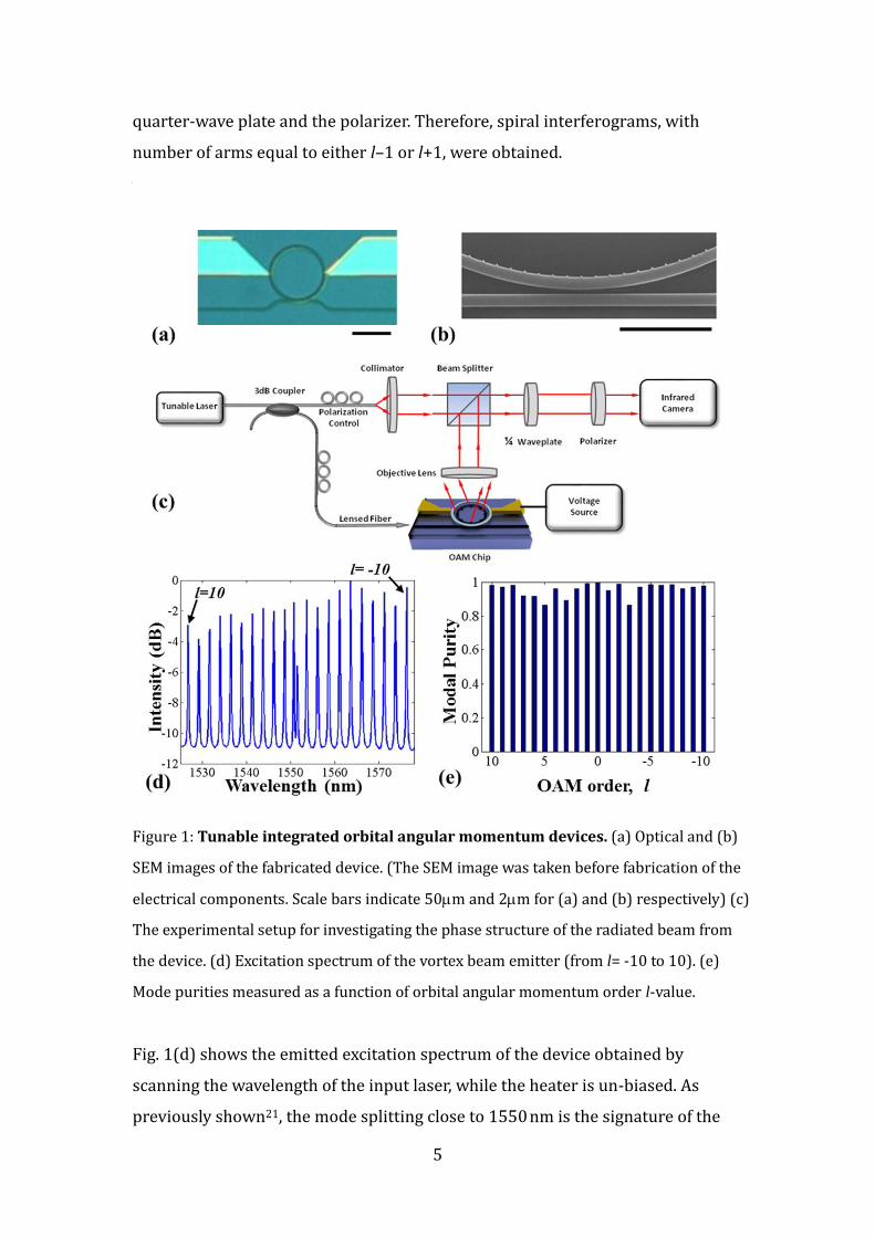
Figure 1: Tunable integrated orbital angular momentum devices. (a) Optical and (b)
SEM images of the fabricated device. (The SEM image was taken before fabrication of the
electrical components. Scale bars indicate 50m and 2m for (a) and (b) respectively) (c)
The experimental setup for investigating the phase structure of the radiated beam from
the device. (d) Excitation spectrum of the vortex beam emitter (from l= -10 to 10). (e)
Mode purities measured as a function of orbital angular momentum order l-value.
Fig. 1(d) shows the emitted excitation spectrum of the device obtained by
scanning the wavelength of the input laser, while the heater is un-biased. As
previously shown21, the mode splitting close to 1550 nm is the signature of the
6
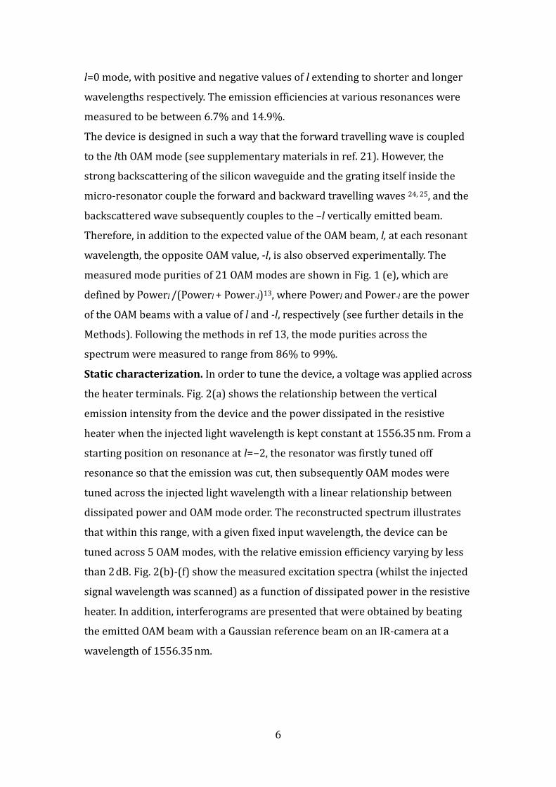
l=0 mode, with positive and negative values of l extending to shorter and longer
wavelengths respectively. The emission efficiencies at various resonances were
measured to be between 6.7% and 14.9%.
The device is designed in such a way that the forward travelling wave is coupled
to the lth OAM mode (see supplementary materials in ref. 21). However, the
strong backscattering of the silicon waveguide and the grating itself inside the
micro-resonator couple the forward and backward travelling waves 24, 25, and the
backscattered wave subsequently couples to the –l vertically emitted beam.
Therefore, in addition to the expected value of the OAM beam, l, at each resonant
wavelength, the opposite OAM value, -l, is also observed experimentally. The
measured mode purities of 21 OAM modes are shown in Fig. 1 (e), which are
defined by Powerl /(Powerl + Power-l)13, where Powerl and Power-l are the power
of the OAM beams with a value of l and -l, respectively (see further details in the
Methods). Following the methods in ref 13, the mode purities across the
spectrum were measured to range from 86% to 99%.
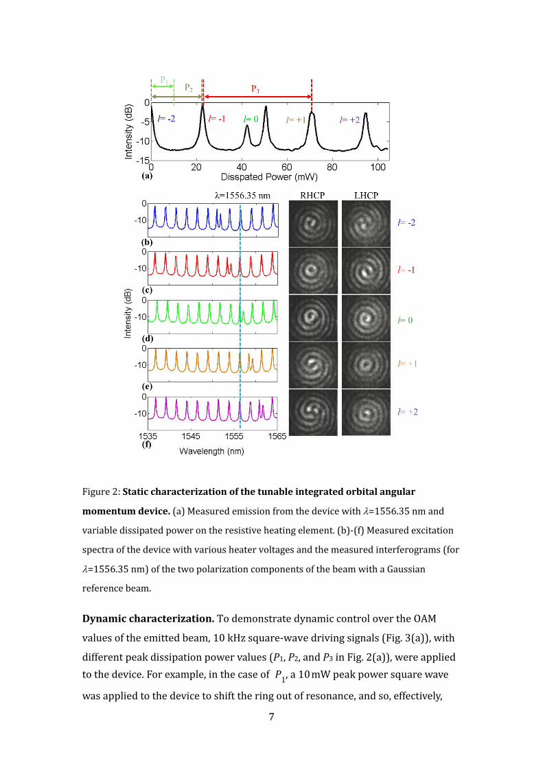
Static characterization. In order to tune the device, a voltage was applied across
the heater terminals. Fig. 2(a) shows the relationship between the vertical
emission intensity from the device and the power dissipated in the resistive
heater when the injected light wavelength is kept constant at 1556.35 nm. From a
starting position on resonance at l=−2, the resonator was firstly tuned off
resonance so that the emission was cut, then subsequently OAM modes were
tuned across the injected light wavelength with a linear relationship between
dissipated power and OAM mode order. The reconstructed spectrum illustrates
that within this range, with a given fixed input wavelength, the device can be
tuned across 5 OAM modes, with the relative emission efficiency varying by less
than 2 dB. Fig. 2(b)-(f) show the measured excitation spectra (whilst the injected
signal wavelength was scanned) as a function of dissipated power in the resistive
heater. In addition, interferograms are presented that were obtained by beating
the emitted OAM beam with a Gaussian reference beam on an IR-camera at a
wavelength of 1556.35 nm.
7
Figure 2: Static characterization of the tunable integrated orbital angular
momentum device. (a) Measured emission from the device with =1556.35 nm and
variable dissipated power on the resistive heating element. (b)-(f) Measured excitation
spectra of the device with various heater voltages and the measured interferograms (for
=1556.35 nm) of the two polarization components of the beam with a Gaussian
reference beam.
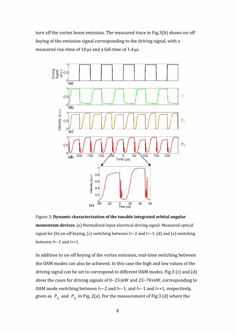
Dynamic characterization. To demonstrate dynamic control over the OAM
values of the emitted beam, 10 kHz square-wave driving signals (Fig. 3(a)), with
different peak dissipation power values (P1, P2, and P3 in Fig. 2(a)), were applied
to the device. For example, in the case of P1, a 10 mW peak power square wave
was applied to the device to shift the ring out of resonance, and so, effectively,
8
turn off the vortex beam emission. The measured trace in Fig.3(b) shows on-off
keying of the emission signal corresponding to the driving signal, with a
measured rise-time of 10 μs and a fall-time of 1.4 μs.
Figure 3: Dynamic characterization of the tunable integrated orbital angular
momentum devices. (a) Normalized input electrical driving signal. Measured optical
signal for (b) on-off keying, (c) switching between l=−2 and l=−1, (d) and (e) switching
between l=−1 and l=+1.
In addition to on-off keying of the vortex emission, real-time switching between
the OAM modes can also be achieved. In this case the high and low values of the
driving signal can be set to correspond to different OAM modes. Fig.3 (c) and (d)
show the cases for driving signals of 0−23 mW and 23−70 mW, corresponding to
OAM mode switching between l=−2 and l=−1, and l=−1 and l=+1, respectively,
given as P2 and P
3 in Fig. 2(a). For the measurement of Fig.3 (d) where the
9
signal sweeps across the double peaked l=0 modes, brief spikes in the temporal
response corresponding to those resonances are clearly visible and are shown in
greater detail in Fig.3 (e), where the asymmetry of the l=0 mode amplitudes can
be used to identify the direction of the spectral mode tuning with time. In this
case the switching time was measured as 20 μs.
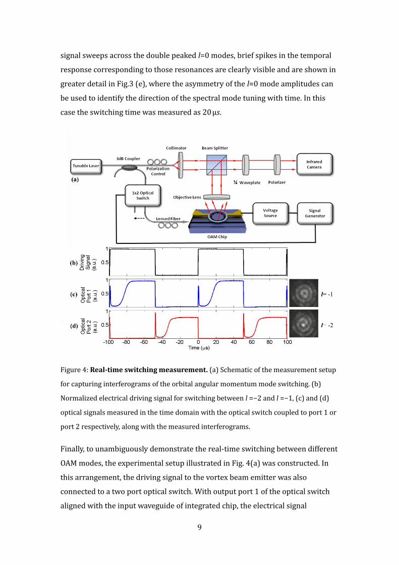
Figure 4: Real-time switching measurement. (a) Schematic of the measurement setup
for capturing interferograms of the orbital angular momentum mode switching. (b)
Normalized electrical driving signal for switching between l =−2 and l =−1, (c) and (d)
optical signals measured in the time domain with the optical switch coupled to port 1 or
port 2 respectively, along with the measured interferograms.
Finally, to unambiguously demonstrate the real-time switching between different
OAM modes, the experimental setup illustrated in Fig. 4(a) was constructed. In
this arrangement, the driving signal to the vortex beam emitter was also
connected to a two port optical switch. With output port 1 of the optical switch
aligned with the input waveguide of integrated chip, the electrical signal
10
synchronized an on-off keying of the optical switch with the OAM switching of
the device. Therefore, as for the continuous wave injection case, an interferogram
of the emitted vortex beam can be measured corresponding to one state of the
switching. The second state can then be measured by simply aligning port 2 of
the optical switch with the input waveguide to the chip. Both of these
interferograms are shown in Fig. 4(b) and (c), along with measured optical
signals from the setup. In this case the electrical signal is 0−23 mW
corresponding to an OAM mode switching between l=−2 and l=−1. The measured
interferograms, created through interference between the linearly polarized
beams converted from RHCP and Gaussian reference beams, clearly show the
expected spiral patterns associated with the predicted OAM states.
Discussion
We report an ultra-compact silicon integrated device capable of rapidly tuning
the OAM modes of emitted light. This is the first demonstration of fast OAM
states switching on-chip, and the switching rate of the device is one to two orders
of magnitude faster than previously demonstrated with bulk-optics approaches.
These switching rates provide an integrated device that can be used in
applications including optical data burst and packet switching26 and quantum
encryption8. Even faster switching among OAM modes, in the order of 100ns,
can be achieved by further optimizing heater designs27 and nano-to-picosecond
switching times are possible by using carrier injection23. Compared to other
photonic integrated circuits with complicated phase-sensitive arrayed waveguide
structures, the tuning of the OAM modes is achieved by the integrated
micro-sized heater, which maintains device simplicity and micron scale footprint.
Following the methods of Gibson et. al. 13, the mode purities of the generated
OAM modes were measured to range from 86% to 99% at various resonances of
the devices, with the undesired OAM mode contribution arising from the
backward travelling wave inside the device due to backscattering in the silicon
waveguide24, 25. In summary, the fully on-chip and single contact control of the
OAM device opens up a wide range of possibilities for applications in sensing and
manipulation28-30, telecommunications3-6 and quantum optics8-10, 31-34.
11
Methods
Devices fabrication and characterization. The micro-ring optical vortex
emitter was fabricated on a silicon on insulator wafer with 220 nm thick silicon
core and 2 μm buried oxide layer. The ring was defined with a radius of 36.6 μm
and q=360 grating elements with a square perturbation cross-section of 60 nm
side length. The device was patterned using direct write electron beam
lithography into a Hydrogen Silsequioxane resist layer. On development the resist
pattern was used as a hard mask for Reactive Ion Etching of the silicon layer. The
silicon device was subsequently coated with a 900 nm thick layer of SiO2 as a
buffer layer between the device and the metal contact layers. The resistive heater
was formed using a lift-off technique with 50 nm of NiCr. The electrical
transmission lines to the heater element was similarly patterned with a 200 nm
thick Au layer. Finally, wire-bonding was carried out for electrical contacting to
the on-chip transmission lines. The resistive heater had a series resistance of
1.5 kΩ and was driven using a constant voltage power supply and an Agilent
33120A function generator. For all emission measurements, light from a tunable
laser (Photonetics, Tunics-BT) was coupled via a lensed optical fibre to the input
waveguide of the silicon chip. The vertical emission of the ring device was
collected with a microscope objective and imaged onto an NIR camera
(Hamamatsu Photonics). For the interferogram measurements a portion of the
source laser light was coupled into a free space Gaussian beam which was
subsequently coaligned with the beam from the vortex emitter for intereference
on the camera. Emitted OAM beams were coupled to an InGaAs amplified
photodetector for the dynamic characterization.
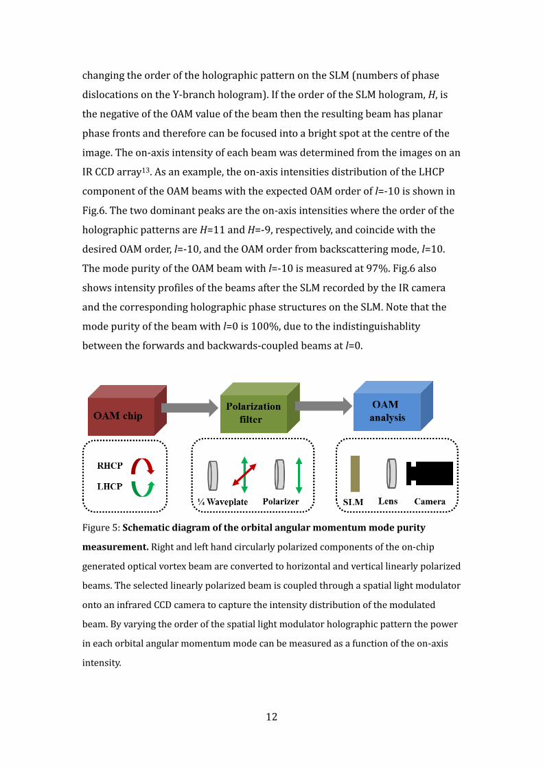
Mode purity measurement. An experimental setup based on a spatial light
modulator (HOLOEYE, PLUTO 1550 SLM), as shown in Fig.5, was used to study
the mode purity of the emitted OAM beam from the device. After going through
the polarization filter, the RHCP or LHCP component of the beam was converted
to a linearly polarized beam with OAM value of l-1 or l+1, dependent on the
relative angle between the axis of the quarter-wave plate and the polarizer. The
polarization filter was used as the SLM can only operate on linearly polarized
light. The OAM order of the linearly polarized beam was then analyzed by
12
changing the order of the holographic pattern on the SLM (numbers of phase
dislocations on the Y-branch hologram). If the order of the SLM hologram, H, is
the negative of the OAM value of the beam then the resulting beam has planar
phase fronts and therefore can be focused into a bright spot at the centre of the
image. The on-axis intensity of each beam was determined from the images on an
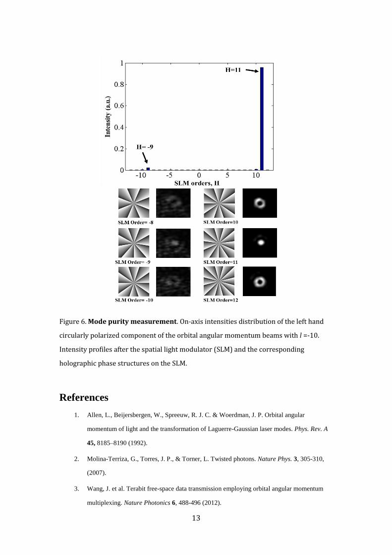
IR CCD array13. As an example, the on-axis intensities distribution of the LHCP
component of the OAM beams with the expected OAM order of l=-10 is shown in
Fig.6. The two dominant peaks are the on-axis intensities where the order of the
holographic patterns are H=11 and H=-9, respectively, and coincide with the
desired OAM order, l=-10, and the OAM order from backscattering mode, l=10.
The mode purity of the OAM beam with l=-10 is measured at 97%. Fig.6 also
shows intensity profiles of the beams after the SLM recorded by the IR camera
and the corresponding holographic phase structures on the SLM. Note that the
mode purity of the beam with l=0 is 100%, due to the indistinguishablity
between the forwards and backwards-coupled beams at l=0.
Figure 5: Schematic diagram of the orbital angular momentum mode purity
measurement. Right and left hand circularly polarized components of the on-chip
generated optical vortex beam are converted to horizontal and vertical linearly polarized
beams. The selected linearly polarized beam is coupled through a spatial light modulator
onto an infrared CCD camera to capture the intensity distribution of the modulated
beam. By varying the order of the spatial light modulator holographic pattern the power
in each orbital angular momentum mode can be measured as a function of the on-axis
intensity.
13
Figure 6. Mode purity measurement. On-axis intensities distribution of the left hand
circularly polarized component of the orbital angular momentum beams with l =-10.
Intensity profiles after the spatial light modulator (SLM) and the corresponding
holographic phase structures on the SLM.
References
1. Allen, L., Beijersbergen, W., Spreeuw, R. J. C. & Woerdman, J. P. Orbital angular
momentum of light and the transformation of Laguerre-Gaussian laser modes. Phys. Rev. A
45, 8185–8190 (1992).
2. Molina-Terriza, G., Torres, J. P., & Torner, L. Twisted photons. Nature Phys. 3, 305-310,
(2007).
3. Wang, J. et al. Terabit free-space data transmission employing orbital angular momentum
multiplexing. Nature Photonics 6, 488-496 (2012).
14
4. Bozinovic, N. et al. Terabit-scale orbital angular momentum mode division multiplexing in
fibers. Science 340, 1545-1548 (2013).
5. Yue, Y. et al. Reconfigurable switching of orbital-angular-momentum-based free-space data
channels. Optics Letters 38, 5118-5121 (2013).
6. Ahmed, N. et al. Reconfigurable 2×2 orbital angular momentum based optical switching of
50-Gbaud QPSK channels. Optics Express 22, 756-761, 2014.
7. Cerf, N., Bourennane, M., Karlsson, A. & Gisin, N. Security of Quantum Key Distribution
Using d-Level Systems. Phys. Rev. Lett. 88, 127902 (2002).
8. Mirhosseini, M., et al. High-dimensional quantum cryptography with twisted light. Preprint
at http://arxiv.org/abs/1402.7113, (2014).
9. Krenn, M., et al. Twisted light communication through turbulent air across Vienna. Preprint
at http://arxiv.org/abs/1402.2602, (2014).
10. Vallone, G., et al. Free-space quantum key distribution by rotation-invariant twisted photons.
Preprint at http://arxiv.org/abs/1402.2932, (2014).
11. Richardson, D. J., Fini, J. M., & Nelson, L. E. Space-division multiplexing in optical fibres.
Nature Photonics 7, 354-362 (2013).
12. Thalhammer, G., Bowman, R.W., Love, G.D., Padgett, M.J., & Ritsch-Marte, M. Speeding
up liquid crystal slms using overdrive with phase change reduction. Optics Express 21,
1779-1797 (2013).
13. Gibson, G. et al. Free-space information transfer using light beams carrying orbital angular
momentum. Opt. Express 12, 5448-5456 (2004).
14. Marrucci, L., Manzo, C., & Paparo, D. Pancharatnam-Berry phase optical elements for wave
front shaping in the visible domain: Switchable helical mode generation. Appl. Phys. Lett. 88,
221102 (2006)
15. Marrucci, L., Manzo, C., & Paparo, D. Optical spin-to-orbital angular momentum
conversion in inhomogeneous anisotropic media. Phys. Rev. Lett. 96, 163905 (2006).
16. Mirhosseini, M., et al. Rapid generation of light beams carrying orbital angular momentum.
Optics Express 21, 30196-30203 (2013).
17. Radwell, N., Brickus, D., Clark, T.W., & Franke-Arnold, S. High speed switching between
arbitrary spatial light profiles. Optics Express 22, 12845-12852 (2014).
15
18. Fontaine, N. K., Doerr, C. R. & Buhl, L. Efficient Multiplexing and Demultiplexing of
Free-space Orbital Angular Momentum using Photonic Integrated Circuits. Opt. Fiber
Commun. Conf. 1, OTu1I.2 (2012).
19. Doerr, C. R., Buhl, L. L. Circular grating coupler for creating focused azimuthally and
radially polarized beams. Opt. Lett. 36, 1209-1211 (2011).
20. Su, T. et al. Demonstration of free space coherent optical communication using integrated
silicon photonic orbital angular momentum devices. Optics Express 20, 9396-9402 (2012).
21. Cai, X. et al. Integrated compact optical vortex beam emitters. Science 33, 363-366 (2012).
22. Dong, P. et al. Low power and compact reconfigurable multiplexing devices based on silicon
microring resonators. Optics Express 18, 9852–9858 (2010).
23. Reed, G.T., Mashanovich, G., Gardes, F. Y., & Thomson, D.J. Silicon optical modulators.
Nature Photonics 4, 518-526 (2010).
24. Morichetti, F. et al. Coherent backscattering in optical microring resonators. Appl. Phys. Lett.
96, 081112 (2010).
25. Morichetti, F. et al., Roughness induced backscattering in optical silicon waveguides. Phys.
Rev. Lett. 104, 033902,( 2010).
26. Yoo, S. J. B. Optical Packet and Burst Switching Technologies for the Future Photonic
Internet. IEEE J. of Lightwave. Tech. 24, 4468–4492 (2006).
27. Atabaki, A. H., Eftekhar, A. A., Yegnanarayanan, S. & Adibi, A. Sub-100-nanosecond
thermal reconfiguration of silicon photonic devices. Optics Express 21, 15706-15718 (2013).
28. Padgett M.,and Bowman, R. Tweezers with a twist. Nature Photonics 5, 343-348, (2011).
29. Yu, Y. F. et al. Pure angular momentum generator using a ring resonator. Optics Express 18,
21 651-62( 2010).
30. Lavery, M. P. J., Speirits, F. C., Barnett, S. M., & Padgett, M. J. Detection of a spinning
object using light’s orbital angular momentum. Science 341, 537–40 (2013).
31. D'Ambrosio, V., et al. Complete experimental toolbox for alignment-free quantum
communication. Nat. Commun. 3, 961-968 (2012).
32. D'Ambrosio, V. et al. Photonic polarization gears for ultra-sensitive angular measurements.
Nat. Commun. 4, 2432 (2013).
16
33. Dada, A. C., Leach, J., Buller, G. S., Padgett, M. J., & Andersson, E. Experimental
high-dimensional two-photon entanglement and violations of generalized Bell inequalities.
Nature Physics 7, 677-680 (2011).
34. Fickler, R. et al. Quantum entanglement of high angular momenta. Science 338, 640-643
(2012).
Acknowledgments
The authors would like to acknowledge support from the EPSRC and the Royal
Academy of Engineering. The project is partially funded by the China National
973 Program through Project No. 2014CB340000. The authors thank the staff of
the James Watt Nanofabrication Centre at the University of Glasgow, and Graham
Marshall and Yunhong Ding for useful discussions.
Author Contributions
M.J.S. and X.C. designed the devices. M.J.S. carried out the fabrication. X.C., J.W., J.Z.,
D.B.P., L.C. and M.L. performed the experiments. All of the authors contributed to
the data analysis and authorship of the manuscript. M.G.T, M.S. and S.Y. developed
and supervised the project.
Competing Financial Interests
The authors declare no competing financial interests.
Figure legends
Figure 1: Tunable integrated orbital angular momentum devices. (a) Optical and (b)
SEM images of the fabricated device. (The SEM image was taken before fabrication of the
electrical components. Scale bars indicate 50m and 2m for (a) and (b) respectively) (c)
The experimental setup for investigating the phase structure of the radiated beam from
the device. (d) Excitation spectrum of the vortex beam emitter (from l= -10 to 10). (e)
Mode purities measured as a function of orbital angular momentum order l-value.
Figure 2: Static characterization of the tunable integrated orbital angular
17
momentum device. (a) Measured emission from the device with =1556.35 nm and
variable dissipated power on the resistive heating element. (b)-(f) Measured excitation
spectra of the device with various heater voltages and the measured interferograms (for
=1556.35 nm) of the two polarization components of the beam with a Gaussian
reference beam.
Figure 3: Dynamic characterization of the tunable integrated orbital angular
momentum devices. (a) Normalized input electrical driving signal. Measured optical
signal for (b) on-off keying, (c) switching between l=−2 and l=−1, (d) and (e) switching
between l=−1 and l=+1.
Figure 4: Real-time switching measurement. (a) Schematic of the measurement setup
for capturing interferograms of the orbital angular momentum mode switching. (b)
Normalized electrical driving signal for switching between l =−2 and l =−1, (c) and (d)
optical signals measured in the time domain with the optical switch coupled to port 1 or
port 2 respectively, along with the measured interferograms.
Figure 5: Schematic diagram of the orbital angular momentum mode purity
measurement. Right and left hand circularly polarized components of the on-chip
generated optical vortex beam are converted to horizontal and vertical linearly polarized
beams. The selected linearly polarized beam is coupled through a spatial light modulator
onto an infrared CCD camera to capture the intensity distribution of the modulated
beam. By varying the order of the spatial light modulator holographic pattern the power
in each orbital angular momentum mode can be measured as a function of the on-axis
intensity.
Figure 6. Mode purity measurement. On-axis intensities distribution of the left hand
circularly polarized component of the orbital angular momentum beams with l =-10.
Intensity profiles after the spatial light modulator (SLM) and the corresponding
holographic phase structures on the SLM.