fast find index - weschler instruments type k-241 & 261 instruments have been designed to...
TRANSCRIPT


FAST FIND INDEX
SWITCHBOARD INSTRUMENTS
Features & Specifications ............................................................................................ ...... K-241, K-241 High Shock, K-261 . ............................................. 1
.........................................................................................................
V-252, H-252 ............................................................................. 6
.........................................................................................................
Synchrotie . ............................................................................. 12
Wattmeter System DataPreferred Scales - Watt & VAR meters . .................................. 14
PANEL INSTRUMENTS
Features & Specifications 20\20 Line. ................................................................................. 15
Conventional Line . ..................................................................... 18
Elapsed Time Line. .................................................................... 22
WESCHLER INSTRUMENTS
16900 Foltz Parkway Cleveland OH 44149
440-238-2550 fax: 440-238-0660
email: [email protected] web: www.weschler.com
REFERENCE INFORMATION
Switchboard Replacement Information. ..................................... 24
Scale Selector Chart - Watt & VAR Meters. .............................. 26
Style Listings - Switchboard....................................................... 30
Style Listings - Panel. ................................................................ 36
WESCHLER INSTRUMENTS
16900 Foltz Parkway Cleveland OH 44149
440-238-2550 fax: 440-238-0660
email: [email protected] web: www.weschler.com

ApplicationType K-241 & 261 instruments have beendesigned to achieve the ultimate in reliabilityand performance. Instruments of this classare recommended for use on electric utilityswitchboards and process control panels forsimilar industrial service.Navy HI-Shock instruments were developedto meet the special needs of the U.S. Navy.These instruments are used almost univer-sally for military shipboard applications. Theymay be used to advantage on commercialmarine and industrial applications or wher-ever humid conditions or severe mechani-cal shocks are sustained.Selection of Type K-241 & 261 instrumentsis indicated whenever there is a need forfrequent, accurate, quick readings andwhere failure in an instrument circuit couldaffect an associated critical circuit.StandardsType K-241 & 261 commercial instrumentscomply with ANSl Standard C39.1 for 1%class switchboard instruments. HI-Shockinstruments meet the stringent requirementsof their associated standards (see table 1).FeaturesTaut-Band SuspensionAll Type K-241 & 261 instruments, exceptthose which rotate continuously, usetaut-band suspension. lnstruments incorpo-rating this feature are identified by the trade-mark tbs . The taut-band suspension instru-ment has certain unique advantages overthe conventional pivot and jewel types:1. lt eliminates friction, giving better accu-
racy and almost perfect repeatability.2. lt gives top performance under adverse
conditions of shock and vibration.3. lt reduces maintenance, thereby saving
money throughout the lifetime of the in-strument.
4. lt assures longer life, reducing annual de-preciation and replacement costs.
5. lt has greater sensitivity, reducing powerburdens on circuits being measured.
EnclosuresThe window of 241 types is shatterproofpolycarbonate.The window of HI-Shock instruments is shat-terproof and 241 types are chemical andscratch resistant. Bases are made from ahigh strength plastic with nontoxic combus-tion products.Cases and hardware for all types are heavilyplated to resist harsh environments.
MechanismsType K-241 and 261 instruments are built withpermanent-magnet moving-coil mechanismsfor all direct current and rectifier types, aswell as for those employing self-contained orexternal transducers. For RNS measurementof alternating current, the mechanisms useiron-vane principles. Both types are built withtaut-band suspensions. The power factormeter and the synchroscope are of the rotat-ing vane type with pivot and jewel bearings.
Full View DesignTo facilitate quick, accurate reading, evenunder adverse conditions, all K-241 instru-ments feature the Westinghouse “full view”design. The window is flat, reducing light re-flection to minimize the need for a non-glaresurface. The dial scale is beveled so thatthere is no dial shadow, making it possibleto read the instrument from a 60-degreeangle.
High Overload CapacityWhile the exact overload capacities vary withratings, the K-241 and 261 instruments gen-erally will withstand momentary overloadsin excess of industry standards without sus-taining damage. For ac instruments thisoverload capacity is in excess of 35 timesnormal current, and for dc it is in excess of150 times. Therefore, it is permissible toselect instruments to read at a preferredthree-quarters scale at normal current andyet permit “pegging” the instrument duringhigh-current transient conditions.
SensitivityDC instruments are available in ratings from100 microamps up. All tbs mechanismshave much lower resistance than their pivotand jewel counterparts and most competi-tive mechanisms.
TYPE KX-261 High Shock
4 1/2 and 8 3/4-inch Rectangular,Type K-241 and 261, For Commercial and Military Service
1

KA-241 Commercial KX-241 High Shock
Notes:1) For readout and bridge circuit.Specifications
Accuracy:1% accuracy class. See AD 43-200 foraccuracy of specific instruments
Case Size:4 1/2-inch class (4 27/61 inches (11.2 cm)square).
Insulation Rating:800 V
Shielding:DC- 1 % influence at 50-200 gauss.AC - 1 % influence at 15 gauss.
Scale Length:7.1 inches (18 0 cm) for 250o rotation.
Net Weight:3 to 5 pounds (1.4 to 2.2 kg), exclusive ofaccessories.
AC Burdens:5A ac ammeter- .375 VAAC wattmeter- 2.0 VA (current coil)AC wattmeter- 2.5 W (potential Coil)150V ac voltmeter- 2.4 WFor details, see Application Data 43-200.
Wiring Diagrams:See Application Data 43-200
Further lnformationOrdering lnformation, Styles & Ratings:See index of this cataloglnstructions: lL 43-241Renewal Parts: RPD 43-241
Modifications
Mechanism Dials:Black with white markingFluorescentDual scaleSpecial colors, trademarks, legends etc.
Windows:Non-glare, Shatterproof
Electrical:lntermediate ratingsSpecial calibrationsOffset or suppressed ZeroMultiple ratingSpecial sensitivity
Mechanical:Pusher or index pointers, Weatherproof,HI-Shock (MIL-S-901C)
Types Available
Function Ranges Type Mechanism Applicable Specification(s)Designation
DC MicroammeterDC MilliameterDC AmmeterDC MillivoltmeterDC Voltmeter
AC MilliammeterAC AmmeterAC VoltmeterAC Frequency MeterAC Frequency MeterAC Frequency MeterAC Power Factor MeterAC Power Factor MeterAC SynchroscopeAC WattmeterAC VarmeterAC Varmeter
Rectifier MilliammeterRectifier AmmeterRectifier Voltmeter
Resistance ThermometerSpeed Indicator (Tachometer)Synchrotie
100uA to 1mA1mA to 1A1A to 50A50mV to 1V1V to 800V
10mA to 1A1A to 20A10V to 750V50, 60 & 400 Hz50, 60 & 400 Hz395-405 Hz0-1-0.5-1-.5........1 to 10A.1 to 10A.1 to 10A
1mA to 1A1A to 17A5V to 600V
All Popular Ranges0-25, up to 13000 PPS0-360o
KX-241 Com & HI, 261 ComKX-241 Com & HI, 261 ComKX-241 Com & HI, 261 ComKX-241 Com & HI, 261 ComKX-241 Com & HI, 261 Com
KA-241 Com & HI, 261 ComKA-241 Com & HI, 261 ComKA-241 Com & HI, 261 ComKX-241 Com & HIKR3-241 ComKR4-241 HIKI-241 Com & HI, 261 ComKJ-241 ComKI-241 Com & HI, 261 ComKP-241 Com & HI, 261 Com & HIKP-241 Com & HI, 261 Com & HIKV-241 Com & HI, 261 Com & HI
KC-241 Com & HI, 261 ComKC-241 Com & HI, 261 ComKC-241 Com & HI, 261 Com
KX-241 Com & HI, 261 ComKR-241 Com & HI, 261 ComKS-241 Com, Unmounted Transmitter
Permanent-magnet moving coilPermanent-magnet moving-coilPermanent-magnet moving-coilPermanent-magnet moving-coilPermanent-magnet moving-coil
Iron VaneIron VaneIron VaneWith Separate TransducerSelf Contained TransducerSelf Contained TransducerRotating VaneSelf Contained TransducerRotating VaneSelf Contained TransducerWith External Phase ShifterSelf Contained Transducer
Permanent-magnet moving-coilPermanent-magnet moving-coilPermanent-magnet moving-coil
Self Contained BridgeSelf Contained TransducerSelf-Synchronous
ANSI C39.1-1981, MIL-M-16034AANSI C39.1-1981, MIL-M-16034AANSI C39.1-1981, MIL-M-16034AANSI C39.1-1981, MIL-M-16034AANSI C39.1-1981, MIL-M-16034A
ANSI C39.1-1981, MIL-M-16034AANSI C39.1-1981, MIL-M-16034AANSI C39.1-1981, MIL-M-16034AANSI C39.1-1981, MIL-M-16125ANSI C39.1-1981MIL-M-23167ANSI C39.1-1981, MIL-M-19261ANSI C39.1-1981ANSI C39.1-1981, MIL-M-16104BANSI C39.1-1981, MIL-W-19088ANSI C39.1-1981ANSI C39.1-1981
ANSI C39.1-1981, MIL-V-23151ANSI C39.1-1981, MIL-V-23151ANSI C39.1-1981, MIL-V-23151
MIL-T-15377F (NOTE 1)ANSI C39.1-1981, MIL-T-16049.......
2
Type K-241 and K-241 High Shock

3
Type K-241 and K
-261
2.813 ( 71)
(commercial grade)
3 phase power factor meters, high shock power factor meters & high shock synchroscopes.

Application
Type 252 edgewise instruments were de-signed specifically for the nuclear powerindustry for use on control panels. How-ever, they are well suited to any use wherehigh reliability and efficient use of spaceare important Considerations.
These instruments incorporate into edge-wise instruments the same taut-band sus-pension system which is used in the high-est quality Weschler portable and switch-board instruments.
They are available in types for direct meas-urement of standard electrical quantities,or in combination with transducers formeasuring any other electrical or mechani-cal quantity capable of being converted intoa proportional electrical quantity.
Standards
There is no published requirement in ANSlC39.1-1981 for instruments of 11/2% ac-curacy class, however; they exceed therequirements for the 2% class specifiedtherein, and may be calibrated to 1% ini-tial accuracy. The type 252 instrumentsmeet the flammability requirements of lEEEStandard 420-1973 and they have passedthe seismic qualification tests under lEEEStandard 344-(1987).
Specifications
Accuracy 1½% of full scaledeflection, horizontalor vertical; ±1% onspecial order
Waveform To 15% of thirdCompensation harmonic content
Momentary ACA & DCA: 10x end scale Overload Capacity ACV: 1.5x DCV: 2x
Working Voltage 1200 volts dc or peak ac,to Ground 800 volts ac rms
Shielding Magnetically shielded
Scale Length 4.5 inches (11.43 Cm)
Net Weight 1½ pounds
Shipping Weight 2½ pounds
Ratings (Self-Contained)
DC: 50 microamperes to 50 amperes50 millivolts to 750 volts
Ac: 10 milliamperes to 20 amperes5 volts to 600 volts
Transducer-type frequency meters, varmeters, wattmeters and
power factor meters are available.
Type 252, 4½” Scale Length 1½% Accuracy
Vertical Type (Grouped)
Horizontal Type
6

Construction: All components aremounted on a plastic drawer which slidesinto a plastic case with a clear, curvedwindow. The entire assembly is treatedto be static free. The plastic is polycar-bonate (ASTM D635) for impact strengthand flame retardance.
Mechanism: The dc instrument is of thepermanent magnet moving-coil type in acore magnet construction.
For ac measurement the same mecha-nism is used, but rectifiers and an rmsnetwork are added. This design permitsthe ac instrument to have a linear scale,to compensate for wave form distortion,and to be practically immune to the ef-fects of magnetic fields from adjacentconductors regardless of their orientation.
Suspension: All type 252 instrumentsuse taut-band suspensions. lnstrumentsincorporating this feature are identified bythe trademark tbs . The absence of fric-tion in taut-band instruments creates theadvantages of perfect repeatability, re-duced maintenance, and lower electricalburdens. The inherent ruggedness of thedesign makes it a top performer underadverse conditions of shock or vibration.
Dials Pointer edge and dial markings areon the same arc so that there is no paral-lax error.
Mounting Instruments may be stackedhorizontally or vertically. Eight edgewisevertical instruments will occupy the samepanel width as three conventional instru-ments. Trim strips, furnished with eachinstrument, finish off the edge of each in-strument or array. Dial cards may be in-terchanged to adapt from horizontal tovertical mounting or to change scales.
Modifications Available:
Internal illumination with low-voltagelamp and translucent dial.
Non-glare window
Dual scale or rating
Straight fine tubular pointer
Offset, center, or suppressed zero
Gasketed construction
Further Information
lnstructions: lnstruction Leaflet 43-252
Transducers: DB 43-840 & 860 Series
Mounting No.of DimensionsFigure 1 shows the two bracket assemblies Instrumentsand two trim strips which are supplied A Bwith each 252 instrument. Figure 2illustrates how these parts are used. 1 1.770(43) 2.166(55)
2 3.510(89) 3.896(99)Two trim strips are needed to trim either 3 5.250(133) 5.620(143)a single instrument or a stacked array. 4 6.990(178) 7.356(187)
5 8.730(222) 9.086(231)6 10.470(266) 10.816(275)7 12.210(310) 12.546(319)8 13.950(354) 14.276(363)
Burden Characteristics at 60 HertzBurdens on Current Transformers at 5 AmpsInstrument Impedance: Resistance: Reactance: Volt-Amperes PercentRating Ohms Ohms Ohms Power Factor
5amp .024 .013 .020 0.6 54
Burden on Potential Transformers at 120 VoltsInstrument Volt- Watts Vars PercentRating Amperes Power Factor
150 volts .096 .096 0 100
LampsLamp Type Volts Amps
46 6.3 0.25
Figure 2: Outline and Drilling Dimensions, In Inches (Millimeters)
Figure 1: Mounting Material Supplied with Instrument
Type 252, 4½” Scale Length 1½% Accuracy
7
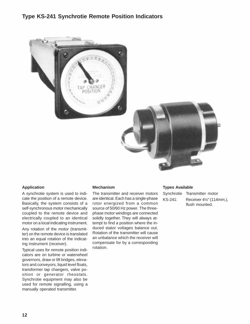
Type KS-241 Synchrotie Remote Position Indicators
12
Application
A synchrotie system is used to indi-cate the position of a remote device.Basically, the system consists of aself-synchronous motor mechanicallycoupled to the remote device andelectrically coupled to an identicalmotor on a local indicating instrument.
Any rotation of the motor (transmit-ter) on the remote device is translatedinto an equal rotation of the indicat-ing instrument (receiver).
Typical uses for remote position indi-cators are on turbine or waterwheelgovernors, draw or lift bridges, eleva-tors and conveyors, liquid level floats,transformer tap changers, valve po-sition or generator rheostats.Synchrotie equipment may also beused for remote signalling, using amanually operated transmitter.
Mechanism
The transmitter and receiver motorsare identical. Each has a single-phaserotor energized from a commonsource of 50/60 Hz power. The three-phase motor windings are connectedsolidly together. They will always at-tempt to find a position where the in-duced stator voltages balance out.Rotation of the transmitter will causean unbalance which the receiver willcompensate for by a correspondingrotation.
Types Available
Synchrotie Transmitter motor
KS-241: Receiver 4½” (114mm,),flush mounted.

Type KS-241 Syn chrotie Remote Position Indicato rs
13
ModificationsDials: Black with white
markingsFluorescent
Wind ows: Non-glareShatterproof
Electrical: Multiple receiversDifferential receivers
SpecificationsMaximum Speed: 200 rpm,
Accura cy: Accuracy is ±1%.Accuracy can be adversely affectedby low line voltage, excessive lineresistance between transmitter andreceiver, or by operating severalreceivers from one transmitter. (Foractual conditions determine errorfrom IL 43-249.)
Power Consumption: 60 VA, 15watts, per motor.
Power Supply: 120 volts, 50/60hertz
Secondary voltage : 57½ volts.
Wiring Di agramsSee Application Data 43-200.
Further InformationOrdering Information & Ratings:This Catalog, Switchboard SectionInstructions: IL 43-249
Outline Dimensions and Drilling Plan , Inches (Millimeters) See Application Data 43-200

In the interest of standardization of preferred wattmeter and varmeter scale markingsfor the common current and potential transformers a listing appears on this page.Such instruments may be supplied with left zero or center zero scales at the same listprice.
Since wattmeter and varmeter current circuits are frequently connected in series, theyshould have equal current carrying capacity. This means that to assure equality thesum of the left and right end-scale values of the varmeter must be equal to or greaterthan the full-scale value of the wattmeter, (or the higher of the end-scale values ifcenter or offset zero). Standard end markings and the proper scale divisions arelisted in Application Data 43-200. If other combinations must be made, check withWeschler.
Scales outside the preferred ranges are available at an extra price for any currenttransformer secondary between .050 and 10 amps at full scale for circular scale, .100and 20 amps for 100o scale and .500 and 10 amps for Edgewise instruments.
Type 221 and 252 instruments 1000 kilowatts and over are marked in megawatts.
Center zero or offset zero varmeters are marked “IN” for left deflection and “OUT” forright deflection.
Preferred scales may be calculated for wattmeters and varmeters not listed on thecharts. Scale watts must be one of the standard full scale dial markings shown on thecharts or on Table A, Application Data 43-200, page 2.
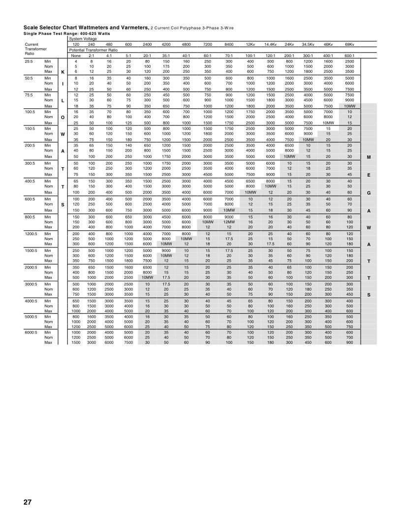
3 phase, 4 wire (3 current coil)MIN =ct ratio x pt ratio x 1.2 (Select next higher scale)NOM =ct ratio x pt ratio x 1.5 (Select nearest scale)MAX =ct ratio x pt ratio x 2.1 (Select next lower scale)
3 phase, 3 wire (2 current coil)MIN =ct ratio x pt ratio x 0.8 (Select next higher scale)NOM =ct ratio x pt ratio x 1.0 (Select nearest scale)MAX =ct ratio x pt ratio x 1.25 (Select next lower scale)
1 phaseMIN =ct ratio x pt ratio x 0.4 (Select next higher scale)NOM =ct ratio x pt ratio x 0.5 (Select nearest scale)MAX =ct ratio x pt ratio x 0.62 (Select next lower scale)
Example: For 3 phase, 3 wire wattmeter with 400:5 ct and 1200:1 pt
MIN = 400/5 x 1200/1 x 0.8 = 77,000 Next higher = 80 MWNOM = 400/5 x 1200/1 x 1.0 = 96,000 Nearest = 100 MWMAX = 400/5 x 1200/1 x 1.25 = 120,000 Next lower = 120 MW
Note: If scale calculates to an exact listed value use it rather thanthe next higher or lower value.
Scale Watts1ph Test Watts = CT ratio x PT ratio x K
WhereK = 1 1 - elementK = 2 2 - elementK = 4 2½ - element
WATT METER SYSTEM DATAPreferred Scales Wattmeters and Varmeters
14

2 1/2" G-332 3 1/2" G-352 4 1/2" G-372 5 1/2" G-382
Bezel StyleNumber
292B767G04 292B767G02 292B767G08 292B767G05
Application
20/20 instruments have neat, cleanlines which harmonize with highlystyled electronic components. Theycan be properly applied on equipmentranging from a spectrometer to a unitof power switchgear.
Readability
20/20 instruments were designed formaximum readability from a distance.The lance-design pointer in conjunc-tion with the bold dial markings makethis instrument the most easily readin its field.
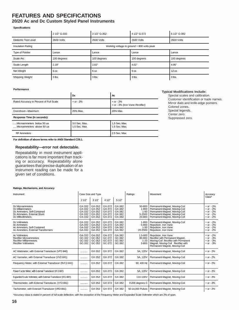
FEATURES AND SPECIFICATIONS20/20 Ac and Dc Custom Styled Panel Instruments
Enclosures
The 20/20 instrument case is madeof a black Lexan plastic, dimensionedto meet the industry standards forCustom Styled Panel Instruments asdefined by ANSI C39.1.
The snap-on cover is made up of ahigh grade Lexan plastic which willremain crystal clear in appearance.It is treated with Weschler Anti-Static
Agent to keep it dust-free, and to in-sure continued freedom from electro-static effects. The side edges of thecover are also of clear plastic, allow-ing light to enter from any angle.
Rear-of-Panel Mounting
Bezels are available for rear-of-panel mounting of each of the foursizes of instruments available.
5 1/2" GA-382 Ac Voltmeter
3 1/2" GX-352 Dc Voltmeter2 1/2" GA-332 Ac Ammeter
4 1/2" GX-372 Dc Voltmeter
15
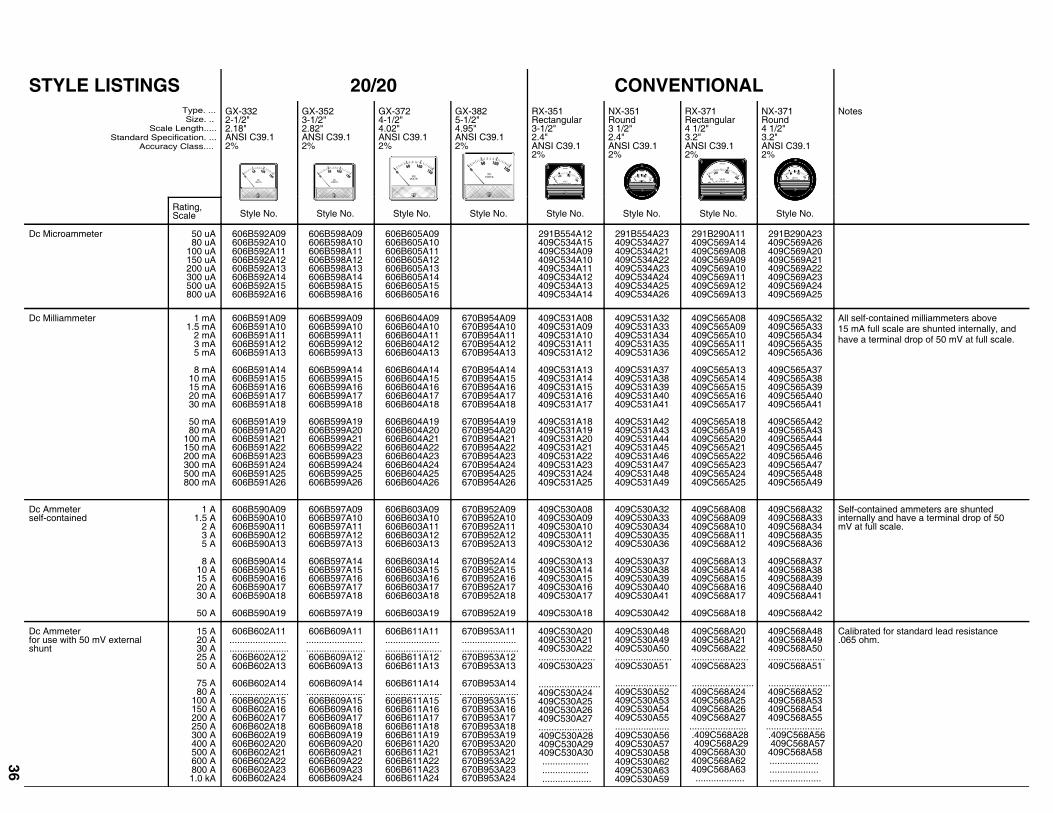
Ratings, Mechanisms, and Accuracy
Instrument Case Size and Type Ratings Movement AccuracyClass*
2 1/2" 3 1/2" 4 1/2" 5 1/2"
Dc MicroammetersDc MilliammetersDc Ammeters, Self-ContainedDc Ammeters, External ShuntDc Millivoltmeters
GX-332GX-332GX-332GX-332GX-332
GX-352GX-352GX-352GX-352GX-352
GX-372GX-372GX-372GX-372GX-372
GX-382GX-382GX-382GX-382GX-382
50-8001-800
1-505-250020-800
Permanent-Magnet, Moving-CoilPermanent-Magnet, Moving-CoilPermanent-Magnet, Moving-CoilPermanent-Magnet, Moving-CoilPermanent-Magnet, Moving-Coil
+ or - 2%+ or - 2%+ or - 2%+ or - 2%+ or - 2%
Dc VoltmetersAc AmmetersAc Ammeters, Self-ContainedAc Ammeters, External Transformers
GX-332GA-332GA-332GA-332
GX-352GA-352GA-352GA-352
GX-372GA-372GA-372GA-372
GX-382GA-382GA-382GA-382
1-8005-800
1-5020-2500
Permanent-Magnet, Moving-CoilRepulsion, Iron VaneRepulsion, Iron VaneRepulsion, Iron Vane
+ or - 2%+ or - 2%+ or - 2%+ or - 2%
Ac VoltmetersRectifier MicroammetersRectifier MilliammetersRectifier Voltmeters
GA-332GC-332GC-332GC-332
GA-352GC-352GC-352GC-352
GA-372GC-372GC-372GC-372
GA-382GC-382GC-382GC-382
1.5-60080-800
1-203-800
Repulsion, Iron VaneRectifier with Permanent Magnet,Moving-Coil Rectifier with PermanentMagnet, Moving-Coil Rectifier withPermanent Magnet, Moving-Coil
+ or - 2%+ or - 3%+ or - 3%+ or - 3%
AC Wattmeter, with External Transducer (VP2-840) ............. GX-352 GX-372 GX-382 5A, 120V Permanent-Magnet, Moving-Coil + or - 2%
AC Varmeter, with External Transducer (VV2-841) ............. GX-352 GX-372 GX-382 5A, 120V Permanent-Magnet, Moving-Coil + or - 2%
Frequency Meter, with External Transducer (9VC2-841) ............. GX-352 GX-372 GX-382 60, 400 Hz Permanent-Magnet, Moving-Coil + or - 2%
Power Factor Meter, with External Transducer (VF2-841) ............. GX-352 GX-372 GX-382 5A, 120V Permanent-Magnet, Moving-Coil + or - 2%
Expanded Scale Voltmeter, with External Transducer (VE2-841) ............. GX-352 GX-372 GX-382 110-130V Permanent-Magnet, Moving-Coil + or - 2%
Thermometer, with External Transducer, (VT2-841) ............. GX-352 GX-372 GX-382 0-200 degrees C Permanent-Magnet, Moving-Coil + or - 2%
Tachometer, with Exteranl Transducer (VR2-841) ............. GX-352 GX-372 GX-382 50-14,000 Pulses Permanent-Magnet, Moving-Coil + or - 2%
*Accuracy class is stated in percent of full scale deflection, with the exception of the Frequency Meter and Expanded Scale Voltmeter which are 2% of span.
16
Typical Modifications Include:Special scales and calibration.Customer identification or trade names.Mirror dials and knife-edge pointers.Colored zones.Special legends.Center zero.Suppressed zero.
Repeatability---error not detectable.Repeatability in most instrument appli-cations is far more important than track-ing or accuracy. Repeatability aloneguarantees that precise duplication of aninstrument reading can be made for agiven set of conditions.
FEATURES AND SPECIFICATIONS20/20 Ac and Dc Custom Styled Panel InstrumentsSpeci ficati ons
2 1/2" G-332 3 1/2" G-352 4 1/2" G-372 5 1/2" G-382
Dielectric Test Level 2600 Volts 2600 Volts 2600 Volts 2600 Volts
Insulation Rating Working voltage to ground = 800 volts peak
Type of Pointer Lance Lance Lance Lance
Scale Arc 100 degrees 100 degrees 100 degrees 100 degrees
Scale Length 2.18" 2.82" 4.02" 4.95"
Net Weight 6 oz. 6 oz. 9 oz. 12 oz.
Shipping Weight 3 lbs. 3 lbs. 3 lbs. 3 lbs.
Perfo rmance
Dc Ac
Rated Accuracy in Percent of Full Scale + or - 2% + or - 2%+ or - 3% (Iron Vane Rectifier)
Overshoot---Maximum 20% Max. 20% Max.
Response Time (in seconds):
.....Microammeters below 50 ua
.....Microammeters above 50 ua3.0 Sec. Max.1.5 Sec. Max.
1.5 Sec. Max.1.5 Sec. Max.
RF Ammeters 2.5 Sec. Max.
For def init ion of above t erms r efer to ANSI Standard C39.1.

Instruments, Outline and Drilling Dimensions in Inches
Type Dimensions in Inches
A B C D E F G (Dia.)
G-332 1 23/32 3 1/8 1 39/64 1 1/2 3 2 9/64 9/32
G-352 2 17/64 355/64 2 5/32 1 55/64 323/32 2 39/64 9/32
G-372 2 29/32 431/32 2 3/4 2 13/32 413/16 3 9/16 3/8
G-382 3 5/16 6 1/16 3 5/32 2 61/64 529/32 4 1/32 3/8
Instrument With Bezel, Outline and Drilling Dimensions in Inches
Type Dimensions in Inches
A B C (Thread Size) D E F G H I J (Dia.) K L M(Dia.)
G-352 3 3 1/2 .138 - 32 (6-32) 2.21 .............. 7/16 1 13/64 2 5/8 1 5/16 0.157 1 3/4 1 13/64 2 1/4
G-372 4 4 1/2 .164 - 32 (8-32) 2.79 0.08 0.568 1 19/32 3 1/2 1 3/4 0.18 2 1/4 1 19/32 3
G-382 4 1/2 5 1/2 .164 - 32 (8-32) 2.79 0.585 1/16 2 3/32 4 1/2 2 1/4 0.18 2 3/4 2 3/32 4
FEATURES AND SPECIFICATIONS20/20 Ac and Dc Custom Styled Panel Instruments
17
WESCHLER INSTRUMENTS www.weschler.com 440-238-2550 fax: 440-238-0660 email: [email protected]
Type G-332
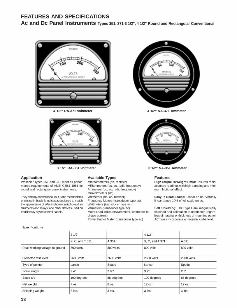
FEATURES AND SPECIFICATIONSAc and Dc Panel Instruments Types 351, 371-3 1/2", 4 1/2" Round and Rectangular Conventional
ApplicationWeschler Types 351 and 371 meet all perfor-mance requirements of ANSI C39.1-1981 forround and rectangular panel instruments.
They employ conventional Taut Band mechanismsenclosed in black fluted cases designed to matchthe appearance of Westinghouse switchboard in-struments and relays, and other devices used ontraditionally styled control panels.
Available TypesMicroammeters (dc, rectifier)Milliammeters (dc, ac, radio frequency)Ammeters (dc, ac, radio frequency)Millivoltmeters (dc)Voltmeters (dc, ac, rectifier)Frequency Meters (transducer type ac)Wattmeters (transducer type ac)Varmeters (transducer type ac)Motor Load Indicators (ammeter, wattmeter, in-phase current)Power Factor Meter (transducer type ac)
FeaturesHigh Torque To Weight Ratio: Insures rapid,accurate readings with high damping and mini-mum frictional effect.
Easy To Read Scales: Linear on dc. Virtuallylinear above 10% of full scale on ac.
Self Shielding: DC types are magneticallyshielded and calibration is unaffected regard-less of material or thickness of mounting panel.AC types incorporate an internal coil-sheild.
4 1/2" NA-371 Ammeter4 1/2" RA-371 Voltmeter
3 1/2" RA-351 Voltmeter 3 1/2" NA-351 Ammeter
Specifications
3 1/2" 4 1/2"
X, C, and T 351 A 351 X, C, and T 371 A 371
Peak working voltage to ground 800 volts 800 volts 800 volts 800 volts
Dielectric test level 2600 volts 2600 volts 2600 volts 2600 volts
Type of pointer Lance Spade Lance Spade
Scale length 2.4" 2.06" 3.2" 2.8"
Scale arc 100 degrees 85 degrees 100 degrees 85 degrees
Net weight 7 oz. 8 oz. 12 oz. 12 oz.
Shipping weight 3 lbs. 3 lbs. 3 lbs. 3 lbs.
18

Application DataAc Panel InstrumentsApproximate Loss (Volt-Amperes) at 60 Hz
Full Scale Rating 20/20 Conventional Full Scale Rating 20/20 Conventional Full Scale Rating 20/20Conventional
10-800 mA 1 vA max. 1 vA max. 2 V (moving iron) 3 vA max. 3 vA max. 100 V (moving iron)3 vA max. 3 vA max.1-3 A 1 vA max. 1 vA max. 3 V (moving iron) 3 vA max. 3 vA max.5 A 1vA max. 1 vA max. 5 V (moving iron) 3 vA max. 3 vA max. 150 V (moving iron)3 vA max. 3 vA max.8 A 1vA max. 1 vA max. 8 V (moving iron) 3 vA max. 3 vA max. 200 V (moving iron)3 vA max. 3 vA max.10 A 1 vA max. 1 vA max. 10 V (moving iron) 3 vA max. 3 vA max. 300 V (moving iron)3 vA max. 3 vA max.15 A 1 vA max. 1 vA max. 500 V (moving iron)3 vA max. 3 vA max.20 A 1 vA max. 1 vA max. 15 V (moving iron) 3 vA max. 3 vA max. 600 V (moving iron)3 vA max. 3 vA max.30 A 2 vA max. 2 vA max. 20 V (moving iron) 3 vA max. 3 vA max.50 A 2 vA max. 2 vA max. 30 V (moving iron) 3 vA max. 3 vA max.
50 V (moving iron) 3 vA max. 3 vA max.1.5 V (moving iron)3 vA max. 3 vA max. 80 V (moving iron) 3 vA max. 3 vA max.
Ratings, Mechanisms, and Accuracy
Instrument Case and TypeRange Range Mechanism Accuracy
3 1/2" 4 1/2"Dc Microammeters ................................................................. RX, NX 351 RX, NX 371 20 to 800 Permanent-Magnet Moving-Coil .......................... + 2%Dc Milliammeters ................................................................... RX, NX 351 RX, NX 371 1 to 800 Permanent-Magnet Moving-Coil .......................... + 2%Dc Ammeters, Self-Contained ............................................. RX, NX 351 RX, NX 371 1 to 50 Permanent-Magnet Moving-Coil .......................... + 2%Dc Ammeters, Shunt Type ................................................... RX, NX 351 RX, NX 371 15 to 1000 Permanent-Magnet Moving-Coil .......................... + 2%Dc Millivoltmeters .................................................................. RX, NX 351 RX, NX 371 50 to 500 Permanent-Magnet Moving-Coil .......................... + 2Dc Voltmeters ......................................................................... RX, NX 351 RX, NX 371 1 to 800 Permanent-Magnet Moving-Coil .......................... + 2%
Ac Milliammeters .................................................................... RA, NA 351 RA, NA 371 5 to 500 Moving Iron ............................................................. + 2%Ac Ammeters, Self-Contained ............................................. RA, NA 351 RA, NA 371 1 to 50 Moving Iron ............................................................. + 2%Ac Ammeters, Transformer Type ........................................ RA, NA 351 RA, NA 371 20 to 3000 Moving Iron ............................................................. + 2%Ac Voltmeters .......................................................................... RA, NA 351 RA, NA 371 1.5 to 800 Moving Iron ............................................................. + 2%
Rectifier Microammeters ...................................................... RC, NC 351 RC, NC 371 100 to 500 Rectifier with Permanent-Magnet Moving-Coil + 2 - +3%Rectifier Milliammeters ......................................................... RC, NC 351 RC, NC 371 1 to 10 Rectifier with Permanent-Magnet Moving-Coil + 2 - +3%Rectifier Voltmeters ............................................................... RC, NC 351 RC, NC 371 5 to 600 Rectifier with Permanent-Magnet Moving-Coil + 2 - +3%
Radio Frequency Milliammeters* ....................................... RT, NT 351 RT, NT 371 10 to 800 Permanent-Magnet Moving-Coil .......................... + 2%Radio Frequency Ammeters, Self-Contained* ................. RT, NT 351 RT, NT 371 1 to 20 Permanent-Magnet Moving-Coil .......................... + 2%Radio Frequency Ammeters, External Type* ......................... RT, NT 351 RT, NT 371 ................ Thermocouple w / Permanent-Magnet Moving-Coil + 2%
Frequency Meters .................................................................. RX, NX 351 RX, NX 371 50-60 Cy. Permanent-Magnet Moving-Coil .......................... + 2%
Wattmeters .............................................................................. RX, NX 351 RX, NX 371 1-10A Permanent-Magnet Moving-Coil .......................... + 2%120-480 V
Varmeters ................................................................................. RX, NX 351 RX, NX 371 1-10 A Permanent-Magnet Moving-Coil .......................... + 2%120-480 V
Motor Load Indicators, Ammeter Type .............................. RA, NA 351 RA, NA 371 5 A Moving Iron ............................................................. + 2%Motor Load Indicators, Wattmeter Type ............................ RA, NA 351 RA, NA 371 .1-10 A Permanent-Magnet Moving-Coil .......................... + 2%Motor Load Indicators, In-Phase Current Type ............... ................. RX 371 5 A Permanent-Magnet Moving-Coil .......................... + 2%Motor Load Indicators, Dc Ammeter Type ........................ RX, NX 351 RX, NX 371 50 mV Permanent-Magnet Moving-Coil .......................... + 2%
Ac Wattmeter with External Transducer (VP2-840) ... RX, NX 351 RX, NX 371 5 A, 120 V Permanent-Magnet Moving-Coil .......................... + 2%Ac Varmeter with External Transducer (VV2-840) ..... RX, NX 351 RX, NX 371 5 A, 120 V Permanent-Magnet Moving-Coil .......................... + 2%Frequency Meter with External Transducer (VC2-841) RX, NX 351 RX, NX 371 60, 400 Hz Permanent-Magnet Moving-Coil .......................... + 2%Power Factor Meter with External Transducer (VF2-841) RX, NX 351 RX, NX 371 5 A, 120 V Permanent-Magnet Moving-Coil .......................... + 2%Suppressed Zero Voltmeter with External Transducer (VE2-841) RC, NC 351 RC, NC 371 110-130 V Permanent-Magnet Moving-Coil .......................... + 2%Thermometer with External Transducer (VT2-841) ... RX, NX 351 RX, NX 371 0-200 0 C Permanent-Magnet Moving-Coil .......................... + 2%
*Scales per FCC 73.39.
FEATURES AND SPECIFICATIONS
19
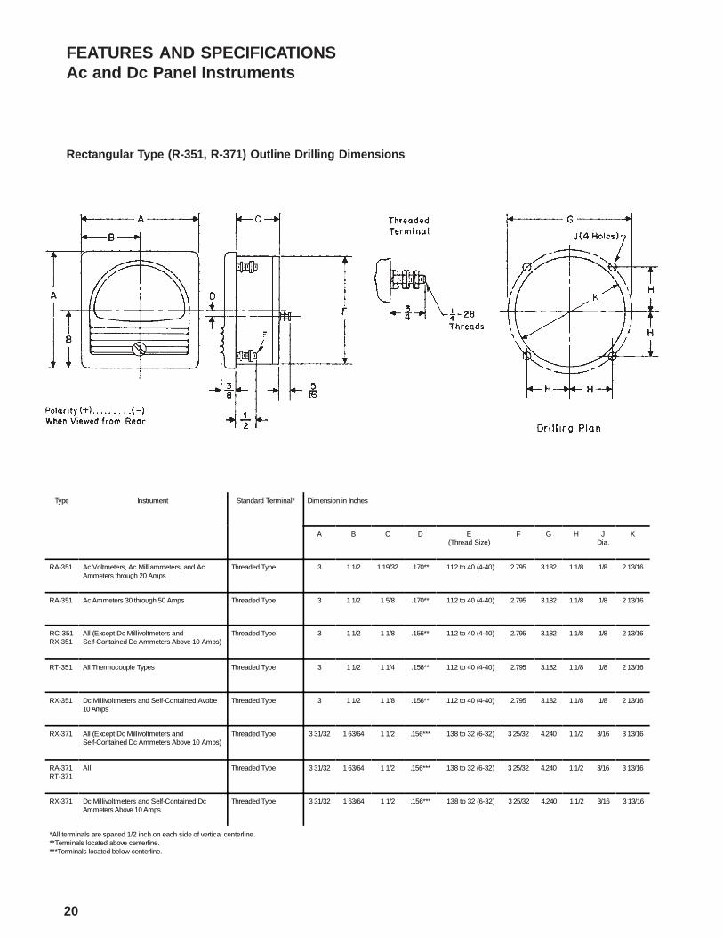
FEATURES AND SPECIFICATIONSAc and Dc Panel Instruments
Rectangula r Type (R-351, R-371) Outline Drilling Dimensions
Type Instrument Standard Terminal* Dimension in Inches
A B C D E(Thread Size)
F G H JDia.
K
RA-351 Ac Voltmeters, Ac Milliammeters, and AcAmmeters through 20 Amps
Threaded Type 3 1 1/2 1 19/32 .170** .112 to 40 (4-40) 2.795 3.182 1 1/8 1/8 2 13/16
RA-351 Ac Ammeters 30 through 50 Amps Threaded Type 3 1 1/2 1 5/8 .170** .112 to 40 (4-40) 2.795 3.182 1 1/8 1/8 2 13/16
RC-351RX-351
All (Except Dc Millivoltmeters andSelf-Contained Dc Ammeters Above 10 Amps)
Threaded Type 3 1 1/2 1 1/8 .156** .112 to 40 (4-40) 2.795 3.182 1 1/8 1/8 2 13/16
RT-351 All Thermocouple Types Threaded Type 3 1 1/2 1 1/4 .156** .112 to 40 (4-40) 2.795 3.182 1 1/8 1/8 2 13/16
RX-351 Dc Millivoltmeters and Self-Contained Avobe10 Amps
Threaded Type 3 1 1/2 1 1/8 .156** .112 to 40 (4-40) 2.795 3.182 1 1/8 1/8 2 13/16
RX-371 All (Except Dc Millivoltmeters andSelf-Contained Dc Ammeters Above 10 Amps)
Threaded Type 3 31/32 1 63/64 1 1/2 .156*** .138 to 32 (6-32) 3 25/32 4.240 1 1/2 3/16 3 13/16
RA-371RT-371
All Threaded Type 3 31/32 1 63/64 1 1/2 .156*** .138 to 32 (6-32) 3 25/32 4.240 1 1/2 3/16 3 13/16
RX-371 Dc Millivoltmeters and Self-Contained DcAmmeters Above 10 Amps
Threaded Type 3 31/32 1 63/64 1 1/2 .156*** .138 to 32 (6-32) 3 25/32 4.240 1 1/2 3/16 3 13/16
*All terminals are spaced 1/2 inch on each side of vertical centerline.**Terminals located above centerline.***Terminals located below centerline.
20

Round Type (N-351, N-371) Outline and Drilling Dimensions
Type Instrument Standard Terminal* Dimension in Inches
A B C DThread Size
E F G H J K LDia.
NA-351 Ac Voltmeters, Ac Milliammeters, and AcAmmeters through 20 Amps
Threaded Type 3 1/2 1 19/32 .170** .138 to 32 (6-32) 2.795 3.16 1.368 1.58 0.79 2 13/16 0.15
NA-351 Ac Ammeters 30 through 50 Amps Threaded Type 3 1/2 1 5/8 .170** .138 to 32 (6-32) 2.795 3.16 1.368 1.58 0.79 2 13/16 0.15
NC-351NX-351
All (Except Dc Millivoltmeters andSelf-Contained Dc Ammeters Above 10 Amps)
Threaded Type 3 1/2 1 1/8 .156** .138 to 32 (6-32) 2.795 3.16 1.368 1.58 0.79 2 13/16 0.15
NT-351 All Thermocouple Types Threaded Type 3 1/2 1 1/4 .156** .138 to 32 (6-32) 2.795 3.16 1.368 1.58 0.79 2 13/16 0.15
NX-351 Dc Millivoltmeters and Self-ContainedAmmeters Above 10 Amps
Threaded Type 3 1/2 1 1/8 .156** .138 to 32 (6-32) 2.795 3.16 1.368 1.58 0.79 2 13/16 0.15
NX-371 All (Except Dc Milliammeters andSelf-Contained Dc Ammeters Above 10 Amps)
Threaded Type 4.562 1 1/2 .156*** .164 to 32 (8-32) 3 25/32 4.126 1.786 2.063 1.032 3 13/16 3/16
NA-371NT-371
All Threaded Type 4.562 1 1/2 .156*** .164 to 32 (8-32) 3 25/32 4.126 1.786 2.063 1.032 3 13/16 3/16
NX-371 Dc Millivoltmeters and Self-Contained DcAmmeters Above 10 Amps
Threaded Type 4.562 1 1/2 .156*** .164 to 32 (8-32) 3 25/32 4.126 1.786 2.063 1.032 3 13/16 3/16
*All terminals are spaced 1/2 inch on each side of vertical centerline.**Terminals located above centerline.***Terminals located below centerline.
FEATURES AND SPECIFICATIONSAc and Dc Panel Instruments
21
Application
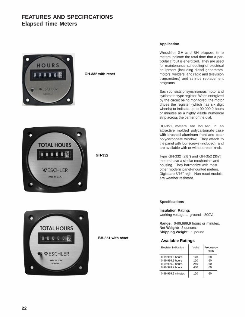
Weschler GH and BH elapsed timemeters indicate the total time that a par-ticular circuit is energized. They are usedfor maintenance scheduling of electricalequipment (including diesel generators,motors, welders, and radio and televisiontransmitters) and service replacementprograms.
Each consists of synchronous motor andcyclometer type register. When energizedby the circuit being monitored, the motordrives the register (which has six digitwheels) to indicate up to 99,999.9 hoursor minutes as a highly visible numericalstrip across the center of the dial.
BH-351 meters are housed in anattractive molded polycarbonate casewith brushed aluminum front and clearpolycarbonate window. They attach tothe panel with four screws (included), andare available with or without reset knob.
Type GH-332 (2½”) and GH-352 (3½”)meters have a similar mechanism and housing. They harmonize with mostother modern panel-mounted meters. Digits are 3/16” high. Non-reset models are weather resistant.
Specifications
Insulation Rating:working voltage to ground - 800V.
Range: 0-99,999.9 hours or minutes.Net Weight: 8 ounces.Shipping Weight: 1 pound.
FEATURES AND SPECIFICATIONSElapsed Time Meters
Available Ratings
Register Indication Volts FrequencyHertz
0-99,999.9 hours0-99,999.9 hours0-99,999.9 hours0-99,999.9 hours
120120240480
50606060
0-99,999.9 minutes 120 60
22
GH-332 with reset
GH-352
BH-351 with reset

FEATURES AND SPECIFICATIONSElapsed Time Meters
Elapsed Time Meters - Outline Dimensions and Drilling Plans in Inches
23

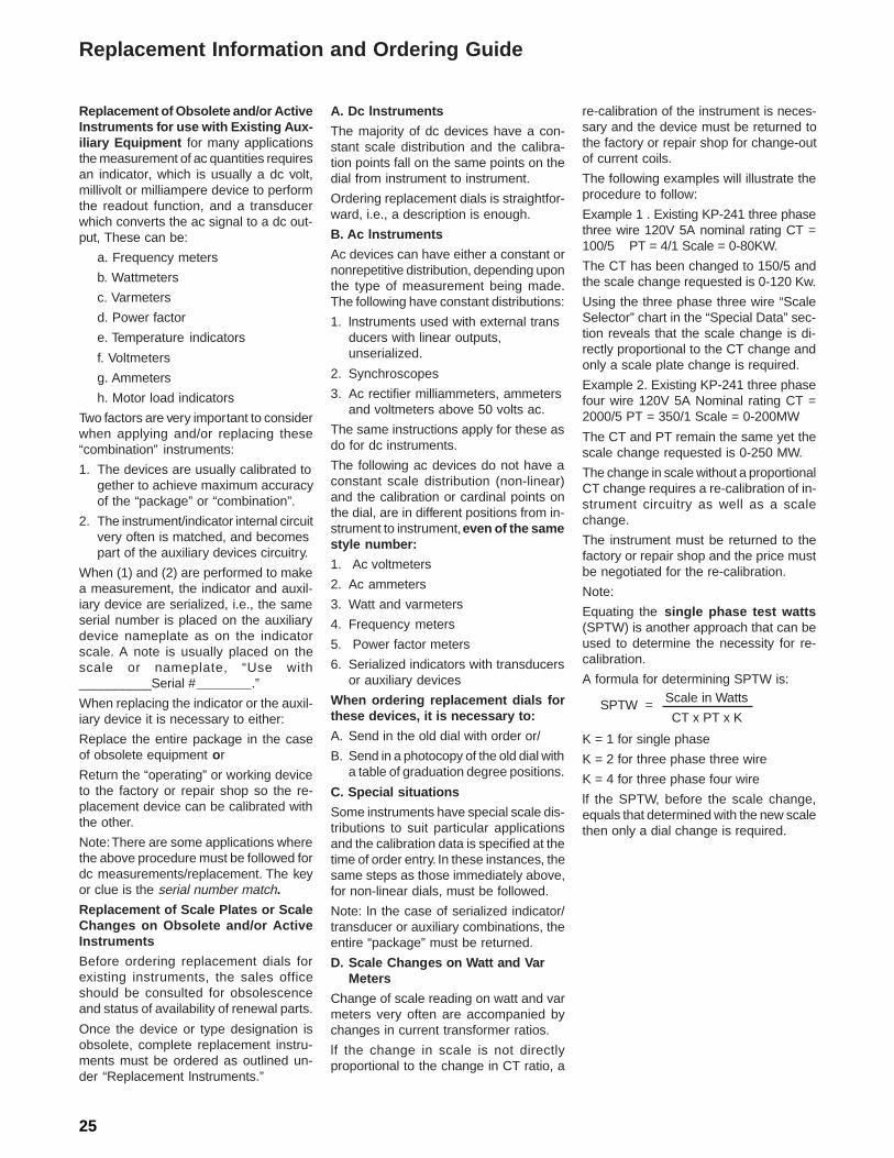
Replacement Information and Ordering Guide
Correct and complete information is nec-essary to provide modern replacement instruments for obsolete or damaged units in the field. Without accurate dial and mask data it is not possible to guarantee that the replacement device will actually perform its intended purpose.
The following definitions will help in “read-ing” the data on existing instruments:
A. Dial - the face of the instrument on which the scale, legend and calibra-tion data are printed.
B. Mask- on circular scale (250O)instruments the mask contains the legend and calibration data.
C. End scale rating (E.S. = the electrical value required to bring pointer from zero to the furthest end of the scale.
D. Full scale rating (F.S. = the electrical value required to sweep pointer the entire scale length.
Note: For example a 100-0-100 MA rat-ing has end scale value of 100 MA and a full scale value of 200 MA.
Ordering information must contain the fol-lowing data:
A. Type (i.e., KX-241, UY-25, VX-252, etc.)
B. Scale marking (numerals)
C. Legend (words or abbreviations describing what these numerals pertain to)
D. Rating (electrical value(s) required to operate the instrument) this should include references to CT, PT used, and frequency.
E. Special features - (black dial, colored zones, non-glare glass, etc.)
F. Style number, shop order number or general order numbers referenced on mask or dial.
G. Nameplate data (recorders, auxiliary devices)
Note: Any other data of any sort printed on the dial or mask should be included.
Example No. 1 Example No. 3
Ordering information should read as follows:
Replacement for Type HC-252, 0-200 scale, AC AMPERES legend, rated 5A used with 200/5CT, 60 Hz, style number 644B015A19.
Ordering information should read as follows:
Replacement for - Type KC-241, 0-60 scale, with legend RPM X1000, rating ES = 10 VAC lMA NOM, shop order 5-24605, with red zone between 50 and 60 on dial.
Ordering information should read as follows:
Replacement for KP-241 , 100-0-100 scale, MEGAVARS legend, rated 5A, 120V max, 7.5A, 1 50V, 2el 2cc, Sphtwatts 260.5 use with 1200/1 at, 50 Hz, marked in on left and out on right, used with phase shifting transformer.
Cover removed, to show dial and mask data markings for accurate ordering information.
Example No. 2
Weschler
24
Replacement of Obsolete and/or Active Instruments for use with Existing Aux -iliary Equipment for many applications the measurement of ac quantities requires an indicator, which is usually a dc volt, millivolt or milliampere device to perform the readout function, and a transducer which converts the ac signal to a dc out-put, These can be:
a. Frequency meters
b. Wattmeters
c. Varmeters
d. Power factor
e. Temperature indicators
f. Voltmeters
g. Ammeters
h. Motor load indicators
Two factors are very important to consider when applying and/or replacing these “combination” instruments:
1. The devices are usually calibrated to gether to achieve maximum accuracy of the “package” or “combination”.
2. The instrument/indicator internal circuit very often is matched, and becomes part of the auxiliary devices circuitry.
When (1) and (2) are performed to make a measurement, the indicator and auxil-iary device are serialized, i.e., the same serial number is placed on the auxiliary device nameplate as on the indicator scale. A note is usually placed on the scale or nameplate, “Use with __________Serial # .”
When replacing the indicator or the auxil-iary device it is necessary to either:
Replace the entire package in the case of obsolete equipment or
Return the “operating” or working device to the factory or repair shop so the re-placement device can be calibrated with the other.
Note: There are some applications where the above procedure must be followed for dc measurements/replacement. The key or clue is the serial number match.
Replacement of Scale Plates or Scale Changes on Obsolete and/or Active Instruments
Before ordering replacement dials for existing instruments, the sales office should be consulted for obsolescence and status of availability of renewal parts.
Once the device or type designation is obsolete, complete replacement instru-ments must be ordered as outlined un-der “Replacement lnstruments.”
A. Dc lnstruments
The majority of dc devices have a con-stant scale distribution and the calibra-tion points fall on the same points on the dial from instrument to instrument.
Ordering replacement dials is straightfor-ward, i.e., a description is enough.
B. Ac lnstruments
Ac devices can have either a constant or nonrepetitive distribution, depending upon the type of measurement being made. The following have constant distributions:
1. lnstruments used with external trans ducers with linear outputs, unserialized.
2. Synchroscopes
3. Ac rectifier milliammeters, ammeters and voltmeters above 50 volts ac.
The same instructions apply for these as do for dc instruments.
The following ac devices do not have a constant scale distribution (non-linear) and the calibration or cardinal points on the dial, are in different positions from in-strument to instrument, even of the same style number:
1. Ac voltmeters
2. Ac ammeters
3. Watt and varmeters
4. Frequency meters
5. Power factor meters
6. Serialized indicators with transducers or auxiliary devices
When ordering replacement dials for these devices, it is necessary to:
A. Send in the old dial with order or/
B. Send in a photocopy of the old dial with a table of graduation degree positions.
C. Special situations
Some instruments have special scale dis-tributions to suit particular applications and the calibration data is specified at the time of order entry. In these instances, the same steps as those immediately above, for non-linear dials, must be followed.
Note: ln the case of serialized indicator/ transducer or auxiliary combinations, the entire “package” must be returned.
D. Scale Changes on Watt and Var Meters
Change of scale reading on watt and var meters very often are accompanied by changes in current transformer ratios.
lf the change in scale is not directly proportional to the change in CT ratio, a
re-calibration of the instrument is neces-sary and the device must be returned to the factory or repair shop for change-out of current coils.
The following examples will illustrate the procedure to follow:
Example 1 . Existing KP-241 three phase three wire 120V 5A nominal rating CT = 100/5 PT = 4/1 Scale = 0-80KW.
The CT has been changed to 150/5 and the scale change requested is 0-120 Kw.
Using the three phase three wire “Scale Selector” chart in the “Special Data” sec-tion reveals that the scale change is di-rectly proportional to the CT change and only a scale plate change is required.
Example 2. Existing KP-241 three phase four wire 120V 5A Nominal rating CT = 2000/5 PT = 350/1 Scale = 0-200MW
The CT and PT remain the same yet the scale change requested is 0-250 MW.
The change in scale without a proportional CT change requires a re-calibration of in-strument circuitry as well as a scale change.
The instrument must be returned to the factory or repair shop and the price must be negotiated for the re-calibration.
Note:
Equating the single phase test watts (SPTW) is another approach that can be used to determine the necessity for re-calibration.
A formula for determining SPTW is:
SPTW = Scale in Watts
CT x PT x K
K = 1 for single phase
K = 2 for three phase three wire
K = 4 for three phase four wire
lf the SPTW, before the scale change, equals that determined with the new scale then only a dial change is required.
Replacement Information and Ordering Guide
25

26
Scale Slector Chart
Wattmeters and Varmeters Single Phase 2-Wire
Scale Selector Chart Wattmeters and Varmeters, Single Phase 2-W ire
S ingle Phase Test Range: 400-625 W atts
System Voltage
Current Transformer Ratio
120 240 480 600 2400 4200 4800 7200 8400 12Kv 14.4Kv 24Kv 34.5Kv 46Kv 69Kv
Potential Transformer Ratio
None 2:1 4:1 5:1 20:1 35:1 40:1 60:1 70:1 100:1 120:1 200:1 300:1 400:1 600:1
25:5 Min 2 4 8 10 40 70 80 120 150 200 250 400 600 800 1200
Nom 2.5 5 10 12 50 90 100 150 175 250 300 500 750 1000 1500
Max K 3 6 12 15 60 100 120 180 200 300 350 600 900 1200 1800
50:5 Min 4 8 16 20 80 150 160 250 300 400 500 800 1200 1600 2500
Nom I 5 10 20 25 100 175 200 300 350 500 600 1000 1500 2000 3000
Max 6 12 25 30 120 200 250 350 400 600 750 1200 1800 2500 3500
75:5 Min 6 12 25 30 120 250 250 400 450 600 750 1200 1800 2500 4000
Nom L 7.5 15 30 40 150 250 300 450 500 750 900 1500 2500 3000 4500
Max 9 18 35 45 180 300 350 500 650 900 1000 1800 2500 3500 5000
100:5 Min 8 16 35 40 160 300 350 500 600 800 1000 1600 2500 3500 5000
Nom O 10 20 40 50 200 350 400 600 700 1000 1200 2000 3000 4000 6000
Max 12 25 50 60 250 400 500 750 800 1200 1500 2500 3500 5000 7500
150:5 Min 12 25 50 60 250 450 500 750 900 1200 1500 2500 4000 5000 7500
Nom W 15 30 60 75 300 500 600 900 1000 1500 1800 3000 4500 6000 9000
Max 18 35 75 90 350 650 750 1000 1200 1800 2000 3500 5000 7500 10MW
200:5 Min 16 35 65 80 350 600 650 1000 1200 1600 2000 3500 5000 6500 10
Nom A 20 40 80 100 400 700 800 1200 1500 2000 2500 4000 6000 8000 12
Max 25 50 100 120 500 800 1000 1500 1750 2500 3000 5000 7500 10MW 15 M
300:5 Min 25 50 100 120 500 900 1000 1500 1750 2500 3000 5000 7500 10 15
Nom T 30 60 120 150 600 1000 1200 1800 2000 3000 3500 6000 9000 12 18
Max 35 75 150 180 750 1200 1500 2000 2500 3500 4500 7500 10MW 15 20 E
400:5 Min 35 65 150 160 650 1200 1500 2000 2500 3500 4000 6500 10 15 20
Nom T 40 80 160 2000 800 1500 1600 2500 3000 4000 5000 8000 12 16 25
Max 50 100 200 250 1000 1750 2000 3000 3500 5000 6000 10MW 15 20 30 G
600:5 Min 50 100 200 250 1000 1750 2000 3000 3500 5000 6000 10 15 20 30
Nom S 60 120 250 300 1200 2000 2500 3500 4000 6000 7000 12 18 25 35
Max 75 150 300 350 1500 2500 3000 4500 5000 7500 9000 15 20 30 45 A
800:5 Min 65 150 300 350 1500 2500 3000 4000 5000 6500 8000 15 20 30 40
Nom 80 160 300 400 1600 3000 3000 5000 6000 8000 10MW 16 25 30 50
Max 100 200 400 500 2000 3500 4000 6000 7000 10MW 12 20 30 40 60 W
1200:5 Min 100 200 400 500 2000 3500 4000 6000 7000 10 12 20 30 40 60
Nom 120 250 500 600 2500 4000 5000 7500 8000 12 15 25 35 50 75
Max 150 300 600 750 3000 5000 6000 9000 10MW 15 17.5 30 45 60 90 A
1500:5 Min 120 250 500 600 2500 4500 5000 7500 9000 12 15 25 40 50 75
Nom 150 300 600 750 3000 5000 6000 9000 10MW 15 18 30 45 60 90
Max 180 350 750 900 3500 6500 7500 10MW 12 18 20 35 50 75 100 T
2000:5 Min 160 350 650 800 3500 6000 6500 10 12 16 20 35 50 65 100
Nom 200 400 800 1000 4000 7000 8000 12 15 20 25 40 60 80 120
Max 250 500 1000 1200 5000 8000 10MW 15 17.5 25 30 50 75 100 120 T
3000:5 Min 250 500 1000 1200 5000 9000 10 15 17.5 25 30 50 75 100 150
Nom 300 600 1200 1500 6000 10MW 12 18 20 30 35 60 90 120 180
Max 350 750 1500 1800 7500 12 15 20 25 35 45 75 100 150 200 S
4000:5 Min 350 650 1500 1600 6500 12 15 20 25 35 40 65 100 150 200
Nom 400 800 1600 2000 8000 15 16 25 30 40 50 80 120 160 250
Max 500 1000 2000 2500 10MW 17.5 20 30 35 50 60 100 150 200 300
5000:5 Min 400 800 1600 2000 8000 16 16 25 30 40 50 80 120 260 250
Nom 500 1000 2000 2500 10MW 20 20 30 35 50 60 100 150 200 300
Max 600 1200 2500 3000 12 25 25 35 40 60 75 120 180 250 350
6000:5 Min 500 1000 2000 2500 10 17.5 20 30 40 50 60 100 150 200 300
Nom 600 1200 2500 3000 12 20 25 35 45 60 75 120 180 250 50
Max 750 1500 3000 3500 15 25 30 45 50 75 90 150 200 300 450
Scale Selector Chart
Wattmeters and Varmeters3 Phase 3-Wire
27
Scale Selector Chart Wattmeters and Varmeters, 2 Current Coil Polyphase 3-Phase 3-W ire
S ingle Phase Test Range: 400-625 W atts
System Voltage
Current Transformer Ratio
120 240 480 600 2400 4200 4800 7200 8400 12Kv 14.4Kv 24Kv 34.5Kv 46Kv 69Kv
Potential Transformer Ratio
None 2:1 4:1 5:1 20:1 35:1 40:1 60:1 70:1 100:1 120:1 200:1 300:1 400:1 600:1
25:5 Min 4 8 16 20 80 150 160 250 300 400 500 800 1200 1600 2500
Nom 5 10 20 25 100 175 200 300 350 500 600 1000 1500 2000 3000
Max K 6 12 25 30 120 200 250 350 400 600 750 1200 1800 2500 3500
50:5 Min 8 16 35 40 160 300 350 500 600 800 1000 1600 2500 3500 5000
Nom I 10 20 40 50 200 350 400 600 700 1000 1200 2000 3000 4000 6000
Max 12 25 50 60 250 400 500 750 800 1200 1500 2500 3500 5000 7500
75:5 Min 12 25 50 60 250 450 500 750 900 1200 1500 2500 4000 5000 7500
Nom L 15 30 60 75 300 500 600 900 1000 1500 1800 3000 4500 6000 9000
Max 18 35 75 90 350 650 750 1000 1200 1800 2000 3500 5000 7500 10MW
100:5 Min 16 35 70 80 350 600 700 1000 1200 1750 2000 3500 5000 7000 10
Nom O 20 40 80 100 400 700 800 1200 1500 2000 2500 4000 6000 8000 12
Max 25 50 100 125 500 800 1000 1500 1750 2500 3000 5000 7500 10MW 15
150:5 Min 25 50 100 120 500 800 1000 1500 1750 2500 3000 5000 7500 15 20
Nom W 30 60 120 150 600 1000 1200 1800 2000 3000 3500 6000 9000 15 25
Max 35 75 150 180 750 1200 1500 2000 2500 3500 4000 7500 10MW 20 30
200:5 Min 35 65 150 140 650 1200 1500 2000 2500 3500 4000 6500 10 15 20
Nom A 40 80 150 200 800 1500 1500 2500 3000 4000 5000 8000 12 15 25
Max 50 100 200 250 1000 1750 2000 3000 3500 5000 6000 10MW 15 20 30 M
300:5 Min 50 100 200 250 1000 1750 2000 3000 3500 5000 6000 10 15 20 30
Nom T 60 120 250 300 1200 2000 2500 3500 4000 6000 7000 12 18 25 35
Max 75 150 300 350 1500 2500 3000 4500 5000 7500 9000 15 20 30 45 E
400:5 Min 65 150 300 350 1500 2500 3000 4000 4500 6500 8000 15 20 30 40
Nom T 80 150 300 400 1500 3000 3000 5000 5000 8000 10MW 15 25 30 50
Max 100 200 400 500 2000 3500 4000 6000 7000 10MW 12 20 30 40 60 G
600:5 Min 100 200 400 500 2000 3500 4000 6000 7000 10 12 20 30 40 60
Nom S 120 250 500 600 2500 4000 5000 7000 8000 12 15 25 35 50 70
Max 150 300 600 750 3000 5000 6000 9000 10MW 15 18 30 45 60 90 A
800:5 Min 150 300 600 650 3000 4500 6000 8000 9000 15 16 30 40 60 80
Nom 150 300 600 800 3000 5000 6000 10MW 12MW 16 20 30 50 60 100
Max 200 400 800 1000 4000 7000 8000 12 12 20 20 40 60 80 120 W
1200:5 Min 200 400 800 1000 4000 7000 8000 12 15 20 25 40 60 80 120
Nom 250 500 1000 1200 5000 8000 10MW 15 17.5 25 15 50 70 100 150
Max 300 600 1200 1500 6000 10MW 12 18 20 30 17.5 60 90 120 180 A
1500:5 Min 250 500 1000 1200 5000 9000 10 15 17.5 25 30 50 75 100 150
Nom 300 600 1200 1500 6000 10MW 12 18 20 30 35 60 90 120 180
Max 350 750 1500 1800 7500 12 15 20 25 35 45 75 100 150 200 T
2000:5 Min 350 650 1500 1600 6500 12 15 20 25 35 40 65 100 150 200
Nom 400 800 1500 2000 8000 15 15 25 30 40 50 80 120 150 250
Max 500 1000 2000 2500 10MW 17.5 20 30 35 50 60 100 150 200 300 T
3000:5 Min 500 1000 2000 2500 10 17.5 20 30 35 50 60 100 150 200 300
Nom 600 1200 2500 3000 12 20 25 35 40 60 70 120 180 250 350
Max 750 1500 3000 3500 15 25 30 40 50 75 90 150 200 300 450 S
4000:5 Min 650 1500 3000 3500 15 25 30 40 45 65 80 150 200 300 400
Nom 800 1500 3000 4000 16 30 30 50 50 80 100 160 250 300 500
Max 1000 2000 4000 5000 20 35 40 60 70 100 120 200 300 400 600
5000:5 Min 800 1600 3500 4000 16 30 35 50 60 80 100 160 250 350 500
Nom 1000 2000 4000 5000 20 35 40 60 70 100 120 200 300 400 600
Max 1200 2500 5000 6000 25 40 50 75 80 120 150 250 350 500 750
6000:5 Min 1000 2000 4000 5000 20 35 40 60 70 100 120 200 300 400 600
Nom 1200 2500 5000 6000 25 40 50 70 80 120 150 250 350 500 700
Max 1500 3000 6000 7500 30 50 60 90 100 150 180 300 450 600 900

Scale Selector Chart Wattmeters and Varmeters, 3 Current Coil 3-Phase 4-W ire
Single Phase Test Range: 313-521 W atts
System Voltage
Current
Transformer
Ratio
208 480 4160 7274 8320 12.47 Kv 14.56 Kv 25 Kv 34.5 Kv 46 Kv 69 Kv
Line To Neutral
120 277 2400 4200 4800 7200 8400 14.4 Kv 20.125 Kv 27.6 Kv 40.25 Kv
Potential Transformer Ratio
None 2.4:1 20:1 35:1 40:1 60:1 70:1 120:1 175:1 240:1 350:1
25:5 Min 7 15 125 250 250 400 450 750 1200 1500 2500
Nom K 8 17.5 150 300 300 500 600 1000 1500 2000 3000
Max 10 20 200 350 400 600 700 1200 1800 2500 3500
50:5 Min 15 30 250 450 500 800 900 1500 2500 3000 4500
Nom I 17.5 35 300 600 600 1000 1200 2000 3000 4000 6000
Max 20 45 400 700 800 1200 1200 2500 3500 5000 7000
75:5 Min 20 45 400 700 750 1200 1500 2500 3500 4500 7000
Nom L 25 65 500 800 1000 1500 1750 3000 4000 6000 9000
Max 30 70 600 1000 1200 1800 2000 3500 5000 7500 10MW
100:5 Min 25 60 500 900 1000 1500 1750 3000 4600 6000 9000
Nom O 35 70 600 1200 1200 2000 2500 4000 6000 8000 12MW
Max 40 90 800 1200 1600 2500 2500 5000 7000 10MW 12
150:5 Min 40 90 750 1500 1500 2500 3000 4500 700 9000 15
Nom W 50 100 1000 1750 2000 3000 3500 6000 8000 12MW 17.5
Max 60 120 1200 2000 2500 3500 4000 7500 10MW 15 20
200:5 Min 50 120 1000 1750 2000 3000 3500 6000 9000 12 17.5
Nom A 70 150 1200 2500 2500 4000 4500 8000 12MW 15 25
Max 80 180 1600 2500 3000 5000 5000 10MW 12 20 25
300:5 Min 75 175 1500 3000 3000 4500 6000 9000 15 18 30
Nom T 100 200 2000 3500 4000 6000 7000 12MW 17.5 25 35
Max 120 250 2500 4000 5000 7500 8000 15 20 30 40
400:5 Min 100 250 2000 3500 4000 6000 7000 12 17.5 25 35
Nom T 120 300 2500 4500 5000 7500 9000 15 25 30 45
Max 160 350 3000 5000 6000 10MW 10MW 20 25 40 50
600:5 Min 150 350 3000 6000 6000 9000 12 18 30 40 60
Nom S 200 450 4000 7000 8000 12MW 15 25 35 50 70
Max 250 500 5000 8000 10MW 15 17.5 30 40 60 80
800:5 Min 200 500 4000 7000 8000 12 15 25 35 50 70
Nom 250 600 5000 9000 10MW 15 17.5 30 45 60 90
Max 300 750 6500 10MW 12 20 20 40 50 80 100
1200:5 Min 300 700 6000 12 12 18 25 40 60 75 120
Nom 400 800 7500 15 15 25 30 50 70 90 150
Max 500 1000 10MW 17.5 20 30 35 60 80 120 175
1500:5 Min 400 900 7500 15 15 25 30 45 70 90 150
Nom 500 1000 10MW 17.5 20 30 35 60 80 120 175
Max 600 1200 12 20 25 35 40 75 100 150 200
2000:5 Min 500 1200 10 17.5 20 30 35 60 90 120 175
Nom 700 1500 12 25 25 40 45 80 120 150 250
Max 800 1800 16 25 30 50 50 100 120 200 250
3000:5 Min 750 1750 15 30 30 45 60 90 150 180 300
Nom 1000 2000 20 35 40 60 70 120 175 250 350
Max 1200 2500 25 40 50 75 80 150 200 300 400
4000:5 Min 1000 2500 20 35 40 60 70 120 175 250 350
Nom 1200 3000 25 45 50 75 90 150 250 300 450
Max 1600 3500 30 50 60 100 100 200 250 400 500
5000:5 Min 1500 3000 25 45 50 80 90 150 250 300 450
Nom 1750 3500 30 60 60 100 120 200 300 400 600
Max 2000 4500 40 75 80 120 120 250 350 500 700
6000:5 Min 1500 3500 30 60 60 90 120 180 300 400 600
Nom 2000 4500 40 70 80 120 150 250 350 500 700
Max 2500 5000 50 80 100 150 175 300 400 600 800

Scale Selector Chart Wattmeters and Varmeters, 3 Current Coil 3-Phase 4-W ire
Single Phase Test Range: 313-521 W atts
System Voltage
Current
Transformer
Ratio
92
Kv
115
Kv
138
Kv
161
Kv
196
Kv
230
Kv
260
Kv
287
Kv
345
Kv
460
Kv
55.2
Kv
69
Kv
80.5
Kv
92
Kv
115
Kv
138
Kv
161
Kv
172.5
Kv
207
Kv
276
Kv
480:1 600:1 700:1 800:1 1000:1 1200:1 1400:1 1500:1 1800:1 2400:1
25:5 Min 3000 4000 4500 5000 7000 7500 9000 10MW 12MW 13MW
M
Nom K 4000 5000 6000 7000 8000 10MW 12MW 12 15 20
Max 5000 6000 7000 8000 10MW 12 12 15 20 25
50:5 Min 6000 8000 9000 10MW 15 15 17.5 20 25 30
ENom I 8000 10MW 12MW 12 17.5 20 25 25 30 40
Max 10MW 12 12 16 20 25 25 30 35 50
75:5 Min 9000 12 15 15 20 25 30 30 35 45
GNom L 12MW 15 17.5 20 25 30 35 35 45 60
Max 15 18 20 25 30 35 40 40 50 75
100:5 Min 12 15 17.5 20 25 30 35 40 45 60
ANom O 15 20 25 25 35 40 45 50 60 80
Max 20 25 25 30 40 50 50 60 75 100
150:5 Min 18 25 30 30 40 45 60 60 70 90
WNom W 25 30 35 40 50 60 70 75 90 120
Max 30 35 40 50 60 75 80 90 100 150
200:5 Min 25 30 35 40 50 60 70 75 90 120
ANom A 30 40 45 50 70 80 90 100 120 150
Max 40 50 50 65 80 100 100 120 150 200
300:5 Min 40 45 60 60 75 90 120 120 150 180
TNom T 50 60 70 75 100 120 150 150 175 250
Max 60 75 80 100 120 150 175 175 200 300
400:5 Min 50 60 70 80 100 120 150 150 180 250
TNom T 60 75 90 100 120 150 175 200 250 300
Max 80 100 100 120 160 200 200 250 300 400
600:5 Min 80 90 120 120 150 180 250 250 300 400
SNom S 100 120 150 150 200 250 300 300 350 500
Max 120 150 175 200 250 300 350 350 450 600
800:5 Min 100 120 150 160 200 250 300 300 400 500
Nom 120 150 175 200 250 300 350 400 500 600
Max 150 200 200 250 300 400 450 500 600 800
1200:5 Min 150 180 250 250 300 400 450 450 600 750
Nom 200 250 300 300 400 500 600 600 750 900
Max 240 300 350 400 500 600 700 750 900 1200
1500:5 Min 180 250 300 300 400 450 600 600 700 900
Nom 250 300 350 400 500 600 700 750 900 1200
Max 300 350 400 500 600 750 800 900 1000 1500
2000:5 Min 250 300 350 400 500 600 700 750 900 1200
Nom 300 400 450 500 700 800 900 1000 1200 1500
Max 400 500 500 650 800 1000 1000 1200 1500 2000
3000:5 Min 400 450 600 600 750 900 1200 1200 1500 1800
Nom 500 600 700 750 1000 1200 1500 1500 1750 2500
Max 600 750 800 1000 1200 1500 1750 1750 2000 3000
4000:5 Min 500 600 700 800 1000 1200 1500 1500 1800 2500
Nom 600 750 900 1000 1200 1500 1750 2000 2500 3000
Max 800 1000 1000 1200 1600 2000 2000 2500 3000 4000
5000:5 Min 600 800 900 1000 1500 1500 1750 2000 2500 3000
Nom 800 1000 1200 1200 1750 2000 2500 2500 3000 4000
Max 1000 1200 1200 1600 2000 2500 2500 3000 3500 5000
6000:5 Min 800 900 1200 1200 1500 1800 2500 2500 3000 4000
Nom 1000 1200 1500 1500 2000 2500 3000 3000 3500 5000
Max 1200 1500 1750 2000 2500 3000 3500 3500 4500 6000
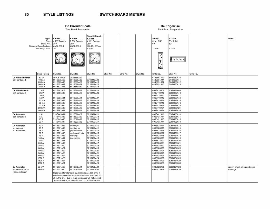
30 STYLE LISTINGS SWITCHBOARD METERS
Dc Circular ScaleTaut Band Suspension
Dc EdgewiseTaut Band Suspension
Type....Size....
Scale Arc.... Standard Specification....
Accuracy Class....
KX-2414 1/2" Square 250o
ANSI C39.1 1%
KX-2618 3/4" Square 250o
ANSI C39.1 1%
Navy HI-Shock KX-241 4 1/2" Square 250o
MIL-M-16034A 1 1/2%
VX-2526" x 1 3/4" 60o
1 1/2%
HX-2526" x 1 3/4" 60o
1 1/2%
Notes:
Scale Rating Style No. Style No. Style No. Style No. Style No. Style No. Style No. Style No. Style No.
Dc MicroammeterseIf-contained
50 uA 100 uA 200 uA 500 uA 750 uA
409C610A25 691B673A09 691B673A10 691B673A12 691B673A13
292B655A29 691B689A26 691B689A27 691B689A29 691B689A30
. . . . . . . . . . 671B419A09 671B419A10 671B419A12 671B419A13
644B651A10 644B651A11 644B651A12 644B651A13 . . . . . . . . . .
644B650A10 644B650A11 644B650A12 644B650A13 . . . . . . . . . .
Dc Milliammeterself-contained
1 mA 2 mA 3 mA 5 mA 10 mA 20 mA 50 mA 200 mA 500 mA
691B687A09 691B687A10 . . . . . . . . . . 691B687A11 691B687A12 691B687A13 691B687A14 691B687A16 691B687A17
691B689A09 691B689A10 . . . . . . . . . . 691B689A11 691B689A12 691B689A13 691B689A14 691B689A16 691B689A17
671B419A25 671B419A26 . . . . . . . . . . 671B419A27 671B419A28 671B419A29 671B419A30 671B419A32 671B419A33
606B419A09 606B419A10 606B419A11 606B419A12 606B419A14 606B419A16 606B419A18 606B419A21 606B419A24
606B432A09 606B432A10 606B432A11 606B432A12 606B432A14 606B432A16 606B432A18 606B432A21 606B432A24
Dc Ammeterself-contained
2 A 5 A 15 A 20 A
714B443A11 714B443A13 714B443A16 714B443A17
691B692A27 691B692A29 691B692A32 691B692A33
671B422A11 671B422A13 671B422A16 671B422A17
606B421A10 606B421A11 606B421A15 606B421A14
606B425A10 606B425A11 606B425A15 606B425A13
Dc Ammeterfor external 50 mV shunts
10 A 15 A 25 A 50 A 75 A 100 A 150 A 200 A 250 A 300 A 400 A 500 A 600 A 1000 A 1500 A 4000 A
691B671A12 691B671A13 691B671A14 691B671A15 691B671A16 691B671A17 691B671A18 691B671A19 691B671A20 691B671A21 691B671A22 691B671A23 691B671A24 691B671A26 691B671A27 691B671A31
Use style number for generic scale and specify dial marking information
671B420A10 671B420A11 671B420A12 671B420A13 671B420A14 671B420A15 671B420A16 671B420A17 671B420A18 671B420A19 671B420A20 671B420A21 671B420A22 671B420A24 671B420A25 671B420A29
606B623A14 606B623A15 606B623A16 606B623A17 606B623A18 606B623A19 606B623A20 606B623A21 606B623A22 606B623A23 606B623A24 606B623A25 606B623A26 606B623A28 606B623A29 606B623A33
606B624A14 606B624A15 606B624A16 606B624A17 606B624A18 606B624A19 606B624A20 606B624A21 606B624A22 606B624A23 606B624A24 606B624A25 606B624A26 606B624A28 606B624A29 606B624A33
Dc Ammeterfor external shunt (Generic Scale)
50 mV 100 mV
691B671A09 691B671A10
691B692A11 691B692A12
671B420A34 671B420A35
606B623A38 606B623A39
606B624A38 606B624A39
Specify shunt rating and scale markings
Calibrated for standard lead resistance .065 ohm. If used with any other resistance between zero and .13 ohm, the error due to lead resistance will not exceed .13% for 50 mV, or .03% for the 100 mV instrument.

31
Dc Circular ScaleTaut Band Suspension
Dc EdgewiseTaut Band Suspension
Type....Size....
Scale Arc.... Standard Specification....
Accuracy Class....
KX-2414 1/2" Square 250o
ANSI C39.1 1%
KX-2618 3/4" Square 250o
ANSI C39.1 1%
Navy HI-Shock KX-241 4 1/2" Square 250o
MIL-M-16034A 1 1/2%
VX-2526" x 1 3/4" 60o
1 1/2%
HX-2526" x 1 3/4" 60o
1 1/2%
Notes:
Scale Rating Style No. Style No. Style No. Style No. Style No. Style No. Style No. Style No. Style No.
Dc Ammeterwith adjustable lead compensation
50 mV 100 mV
691B671A36 691B671A37
691B692A09 691B692A10
. . . . . . . . . .
. . . . . . . . . .644B121A09 644B121A10
644B122A09 644B122A10
Dc Millivoltmeterself-contained
50 mV 100 mV 200 mV 500 mv
714B449A09 714B449A10 714B449A11 714B449A12
714B462A09 714B462A10 714B462A11 714B462A12
. . . . . . . . . .
. . . . . . . . . .
. . . . . . . . . .
. . . . . . . . . .
606B623A09 606B623A10 606B623A11 606B623A12
606B624A09 606B624A10 606B624A11 606B624A12
Dc Voltmeterself-contained
1 V 2 V 5 V 8 V 10 V 15 V 30 V 80 V 100 V 150 V 300 V 600 V 800 V
. . . . . . . . . . 691B672A09 691B672A10 691B672A11 691B672A38 691B672A12 691B672A13 691B672A14 691B672A37 691B672A15 691B672A16 691B672A18 691B672A19
. . . . . . . . . . 691B690A09 691B690A10 691B690A11 . . . . . . . . . . 691B690A12 691B690A13 691B690A14 . . . . . . . . . . 691B690A15 691B690A16 691B690A18 691B690A19
. . . . . . . . . . 671B421A09 671B421A10 671B421A11 . . . . . . . . . . 671B421A12 671B421A13 671B421A14 671B421A21 671B421A15 671B421A16 671B421A18 671B421A19
606B413A22 606B413A09 606B413A10 606B413A11 606B413A12 606B413A13 606B413A14 606B413A16 606B413A17 606B413A18 606B413A19 606B413A20 606B413A23
606B454A22 606B454A09 606B454A10 606B454A11 606B454A12 606B454A13 606B454A14 606B454A16 606B454A17 606B454A18 606B454A19 606B454A20 606B454A23
Dc Voltmeterself-contained Zener type suppressed zero
200-300 V 714B450A14 . . . . . . . . . . . . . . . . . . . . . . . . . . . . . . . . . . . . . . . . . . . . . . . . . . . . . . . . . . . . . . . . . . . . . . . . . . . . . . . .
Dc Ground Detectorfor use with separate resistors
.5-0-.5 mA 691B673A34 691B689A38 671B421A38 . . . . . . . . . . . . . . . . . . . . External Resistors are contained in circular scale Modifications Section
32
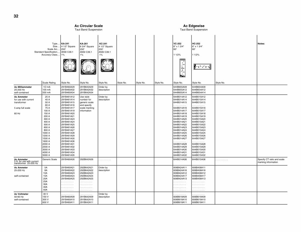
Ac Circular ScaleTaut Band Suspension
Ac EdgewiseTaut Band Suspension
Type....Size....
Scale Arc.... Standard Specification....
Accuracy Class....
KA-2414 1/2" Square 250o
ANSI C39.1 1%
KA-2618 3/4" Square 250o
ANSI C39.1 1%
KC-241 4 1/2" Square 250o
ANSI C39.1 1%
VC-2526" x 1 3/4" 60o
1 1/2%
HC-2526" x 1 3/4" 60o
1 1/2%
Notes:
Scale Rating Style No. Style No. Style No. Style No. Style No. Style No. Style No. Style No. Style No.
Ac Milliammeter 25-200 Hz seIf-contained
1O mA 100 mA 500 mA
291B460A29 291B460A32 291B460A34
291B642A29 291B642A32 291B642A34
Order bydescription
644B655A09 644B655A12 644B655A14
644B654A09 644B654A12 644B654A14
Ac Ammeterfor use with current transformer
5 amp full scale
60 Hz
25 A 40 A 50 A 60 A 75 A 100 A 150 A 200 A 300 A 400 A 500 A 600 A 800 A
1000 A 1200 A 1500 A 1600 A 2000 A 2500 A 3000 A 4000 A 5000 A
291B461A12 291B461A14 291B461A15 291B461A16 291B461A17 291B461A19 291B461A20 291B461A21 291B461A23 291B461A24 291B461A25 291B461A26 291B461A27 291B461A28 291B461A29 291B461A30 291B461A36 291B461A31 291B461A32 291B461A33 291B461A34 291B461A35
Use style number for generic scale and specify scale marking information
Order by description
644B014A12 644B014A14 644B014A15 . . . . . . . . . . 644B014A16 644B014A17 644B014A18 644B014A19 644B014A20 644B014A21 644B014A22 644B014A23 644B014A24 644B014A25 644B014A26 644B014A27 . . . . . . . . . . 644B014A28 644B014A29 644B014A30 644B014A31 644B014A32
644B015A12 644B015A14 644B015A15 . . . . . . . . . . 644B015A16 644B015A17 644B015A18 644B015A19 644B015A20 644B015A21 644B015A22 644B015A23 644B015A24 644B015A25 644B015A26 644B015A27 . . . . . . . . . . 644B015A28 644B015A29 644B015A30 644B015A31 644B015A32
Ac Ammeter5 A, for use with current transformer 25-200 Hz
Generic Scale 291B460A26 292B642A26 . . . . . . . . . . 644B014A08 644B015A08 . . . . . . . . . . Specify CT ratio and scale marking information
Ac Ammeter25-200 Hz
self-contained
5A 8A 10A 15A 20A 25A 30A 40A 50A
291B460A21 291B460A22 291B460A23 291B460A24 291B460A25 . . . . . . . . . . . . . . . . . . . . . . . . . . . . . . . . . . . . . . . .
292B642A21 292B642A22 292B642A23 292B642A24 292B642A25 . . . . . . . . . . . . . . . . . . . . . . . . . . . . . . . . . . . . . . . .
Order by description
606B424A11 606B424A16 606B424A12 606B424A17 606B424A13 . . . . . . . . . . . . . . . . . . . . . . . . . . . . . . . . . . . . . . . .
606B458A11 606B458A16 606B458A12 606B458A17 606B458A13 . . . . . . . . . . . . . . . . . . . . . . . . . . . . . . . . . . . . . . . .
Ac Voltmeter50-60 Hz self-contained
30 V 150 V 300 V 600 V
. . . . . . . . . . 291B460A09 291B460A10 291B460A11
. . . . . . . . . . 291B642A09 291B642A10 291B642A11
Order bydescription
. . . . . . . . . . 606B618A09 606B618A10 606B618A11
. . . . . . . . . . 606B619A09 606B619A10 606B619A11

33
Ac Circular ScaleTaut Band Suspension
Ac EdgewiseTaut Band Suspension
Type....Size....
Scale Arc.... Standard Specification....
Accuracy Class....
KA-2414 1/2" Square 250o
ANSI C39.1 1%
KA-2618 3/4" Square 250o
ANSI C39.1 1%
Navy HI-Shock KC-241 4 1/2" Square 250o
VC-2526" x 1 3/4" 60o
1 1/2%
HC-2526" x 1 3/4" 60o
1 1/2%
Notes:
Scale Rating Style No. Style No. Style No. Style No. Style No. Style No. Style No. Style No. Style No.
Ac Voltmeterfor use with potential transformer 50-60 Hz
300 V 600 V 3000 V 5000 V 9000 V5.25 kV 15 kV 18 kV
291B462A14 291B462A09 291B462A10 291B462A11 . . . . . . . . . . . . . . . . . . . . 291B462A12 291B462A13
. . . . . . . . . .
. . . . . . . . . .
. . . . . . . . . .
. . . . . . . . . .
. . . . . . . . . .
. . . . . . . . . .
. . . . . . . . . .
. . . . . . . . . .
. . . . . . . . . . 644B018A10 644B018A11 . . . . . . . . . . 644B018A14 644B018A12 . . . . . . . . . . 644B018A16
. . . . . . . . . . 644B019A10 644B018A11 . . . . . . . . . . 644B019A14 644B019A12 . . . . . . . . . . 644B019A16
150 V Endscale ""
143 V Endscale 150 V Endscale
" 125 V Endscale 150 V Endscale
Ac Voltmeterscale not listed above Use with potential transformer 25-100 Hz
125 V 143 V 150 V
291B460A15 291B460A08 291B460A12
. . . . . . . . . . 292B642A08 292B642A12
. . . . . . . . . .
. . . . . . . . . .
. . . . . . . . . .
. . . . . . . . . .
. . . . . . . . . .
. . . . . . . . . .
Ac Voltmeterelectrically suppressed zero (Zener) 25-1000 Hz
KC-241 KC-241 VC-252 HC-252
90-130 V 100-140 V 110-130 V 105-125 V
714B461A09 714B461A10 714B461A12 714B461A17
714B503A09 714B503A10 714B503A12 714B503A14
670B121A13 670B121A10 670B121A09 . . . . . . . . . .
670B122A13 670B122A10 670B122A09 . . . . . . . . . .
Ac Voltmeterexpanded scale (Zener) 25-1000 Hz
0-110--130 V 691B229A10 691B230A10 . . . . . . . . . . . . . . . . . . . . . . . . . . . . . . . . . . . . . . . . . . . . . . . . . . . . . . . . . . . . . . . . . . . . . .
Ac Voltmeterelectrically suppressed zero (Zener) 400 Hz
KC-241MIL-V-23151
430-470 V . . . . . . . . . . . . . . . . . . . . 717B216A14 . . . . . . . . . . . . . . . . . . . . . . . . . . . . . . . . . . . . . . . . . . . . . . . . . . . . . . . . . . . .
Ac VoltmeterRectifier
self-contained 20-10,000 Hz
5 V 20 V 50 V 150 V
714B317A09 714B317A11 714B317A12 714B317A14
714B320A09 714B320A11 714B320A12 714B320A14
671B424A09 671B424A11 671B424A12 671B424A14
. . . . . . . . . .
. . . . . . . . . .
. . . . . . . . . .
. . . . . . . . . .
. . . . . . . . . .
. . . . . . . . . .
. . . . . . . . . .
. . . . . . . . . .
Resistance Thermometer
KX-241 KX-261 KX-241MIL-T-2867B
self-contained 120 volt, 60 Hz
0-150 Co
0-200 Co
0-200 Fo
20-140 Co
714B466A10 714B466A11 714B466A12 714B466A17
714B504A10 714B504A11 714B504A12 . . . . . . . . . .
714B466A30 714B466A31 714B466A32 . . . . . . . . . .
. . . . . . . . . .
. . . . . . . . . .
. . . . . . . . . .
. . . . . . . . . .
. . . . . . . . . .
. . . . . . . . . .
. . . . . . . . . .
. . . . . . . . . .
For use with 10 ohm copper coil
Resistance Thermometer 20 Vdc
0-150 C 409C610A33 292B658A10 . . . . . . . . . . . . . . . . . . . . . . . . . . . . . . . . . . . . . . . . For use witho
10 ohm copper coil

34
Ac Circular ScaleTaut Band Suspension
Ac EdgewiseTaut Band Suspension
Type....Size....
Scale Arc.... Standard Specification....
Accuracy Class....
KX-2414 1/2" Square 250o
ANSI C39.1 1%
KX-2618 3/4" Square 250o
ANSI C39.1 1%
Navy HI-Shock KX-241 4 1/2" Square 250o
MIL-T-2867B 1 1/2%
VR3-2526" x 1 3/4" 60o
1 1/2%
HR3-2526" x 1 3/4" 60o
1 1/2%
Notes:
Scale Rating Style No. Style No. Style No. Style No. Style No. Style No. Style No. Style No. Style No.
KR3-241 KR3-261 KX-241
Frequency Meter120 volt self-contained
59-61 Hz 58-62 Hz 55-65 Hz 50-70 Hz 45-55 Hz 45-65 Hz 350-450 Hz
714B538A15 714B538A16 714B538A09 714B538A10 714B538A11 714B538A12 714B538A13
714B505A15 714B505A16 714B505A09 714B505A10 714B505A11 714B505A12 714B505A13
. . . . . . . . . .
. . . . . . . . . .
. . . . . . . . . .
. . . . . . . . . .
. . . . . . . . . .
. . . . . . . . . .
. . . . . . . . . .
670B408A15 670B408A14 670B408A13 670B408A12 670B408A09 670B408A11 670B408A16
670B409A15 670B409A14 670B409A13 670B409A12 670B409A09 670B409A11 670B409A16
Frequency Meter120 volt, with external transducer
KX-241 MIL-M-16125
55-65 Hz 350-450 Hz
. . . . . . . . . .
. . . . . . . . . .. . . . . . . . . . . . . . . . . . . .
291B270A10 291B270A13
. . . . . . . . . .
. . . . . . . . . .. . . . . . . . . . . . . . . . . . . .
Power Factor Meter KJ-241 KJ-261 VX-252 HX-252 HX and VX-252 supplied with external transducer type VF2-841
5A, 60Hz 1ph 120 V
3ph, 3-W 120 V, 480 V Self-contained 3ph, 4-W 120/208 V
.5 - 1 - .5 (Lag - Lead) 775B221A09
775B221A11 775B221A14
775B221A13
775B265A09
775B265A11 775B265A14
775B265A13
. . . . . . . . . .
. . . . . . . . . .
. . . . . . . . . .
. . . . . . . . . .
. . . . . . . . . .
671B379A09 . . . . . . . . . .
. . . . . . . . . .
. . . . . . . . . .
671B379A25 . . . . . . . . . .
. . . . . . . . . .
Power Factor Meter5A, 120 V, 60Hz
KI-241 KI-261 KI-241MIL-S-16104
1 Phase, 2 Quadrant3 PH 3 W, 2 Quadrant
0 - 1 - 0 (Lag - Lead)
186A236A01 186A237A01
186A242A01 186A241A01
292B703A18 292B703A30
. . . . . . . . . .
. . . . . . . . . .. . . . . . . . . . . . . . . . . . . .
SynchroscopeSelf-Contained
120 V, 60 Hz 120 V, 50 Hz 120 V, 400 Hz
Slow - Fast186A235A01 186A662A01 . . . . . . . . . .
186A243A01 186A659A01 . . . . . . . . . .
292B703A09 . . . . . . . . . . 292B703A10
. . . . . . . . . .
. . . . . . . . . .
. . . . . . . . . .
. . . . . . . . . .
. . . . . . . . . .
. . . . . . . . . .

35
Ac Circular ScaleTaut Band Suspension
Ac Edgewise Taut Band Suspension
Type....Size....
Scale Arc.... Standard Specification....
Accuracy Class....
KP2414 1/2" Square 250o
ANSI C39.1 1%
KP2618 3/4" Square 250o
ANSI C39.1 1%
Navy HI-Shock KP241 4 1/2" Square 250o
MIL-M-16034A 1 1/2%
VX2526" x 1 3/4" 60o
1 1/2%
HX2526" x 1 3/4" 60o
1 1/2%
Notes:
Scale Rating Style No. Style No. Style No. Style No. Style No. Style No. Style No. Style No. Style No.
Ac Wattmeter50-60 Hz 1 element, 1 phase
5A
120 V
120 V
480 V
120 V
409C711A18
409C711A37
265C081A39
409C711A57
292B888A20
292B889A40
. . . . . . . . . .
292B890A59
409C685A20
409C685A40
. . . . . . . . . .
409C685A59
714B607A09
714B607A10
. . . . . . . . . .
714B607A11
714B611A09
714B611A10
. . . . . . . . . .
714B611A11
VX and HX-252 and EX-251 Wattmeters supplied with external transducer type VP2-840.
Others are self-contained.
Ac VarmeterWith separate phase shifter 50-60 Hz
2 elem., 3 ph., 3 w. 60 Hz
5A 120V
409C711A62 292B889A30 409C685A62 . . . . . . . . . . . . . . . . . . . .
Three phase types include MV-832 Phase Shifter.
Ac Varmeter50-60 Hz
KV-241 KV-261 VX and HX-252 and EX-251 Varmeters supplied with external transducer type VV2-840.
2 elem., 3 ph., 3 w.
2 1/2 elem., 3 ph., 4 w.
5A 120 V
205C094A19
205C094A47
718B390A21
718B394A20
. . . . . . . . . .
. . . . . . . . . .
714B607A26
714B607A27
. . . . . . . . . .
. . . . . . . . . .
2 elem., 1 ph., 3 w. or 2 elem., 3 ph., 3 w.
2 1/2 elem., 3 ph., 4 w.
2 elem., 1 ph., 3 w. or 2 elem., 3 ph., 3 w.

35a
STYLE LISTINGS 20/20 CONVENTIONALType. ...Size. ..
Scale Length.....Standard Specification. ...
Accuracy Class....
GX-332 2-1/2" 2.18" ANSI C39.1 2%
GX-352 3-1/2 " 2.82" ANSI C39.1 2%
GX-372 4-1/2" 4.02" ANSI C39.1 2%
GX-382 5-1/2" 4.95" ANSI C39.1 2%
RX-351 Rectangular 3-1/2" 2.4" ANSI C39.1 2%
NX-351 Round 3 1/2" 2.4" ANSI C39.1 2%
RX-371 Rectangular 4 1/2" 3.2" ANSI C39.1 2%
NX-371 Round 4 1/2" 3.2" ANSI C39.1 2%
Notes
Rating,Scale Style No. Style No. Style No. Style No. Style No. Style No. Style No. Style No.
Dc Microammeter 50 uA 80 uA
100 uA 150 uA 200 uA 300 uA 500 uA 800 uA
606B592A09 606B592A10 606B592A11 606B592A12 606B592A13 606B592A14 606B592A15 606B592A16
606B598A09 606B598A10 606B598A11 606B598A12 606B598A13 606B598A14 606B598A15 606B598A16
606B605A09 606B605A10 606B605A11 606B605A12 606B605A13 606B605A14 606B605A15 606B605A16
291B554A12 409C534A15 409C534A09 409C534A10 409C534A11 409C534A12 409C534A13 409C534A14
291B554A23 409C534A27 409C534A21 409C534A22 409C534A23 409C534A24 409C534A25 409C534A26
291B290A11 409C569A14 409C569A08 409C569A09 409C569A10 409C569A11 409C569A12 409C569A13
291B290A23 409C569A26 409C569A20 409C569A21 409C569A22 409C569A23 409C569A24 409C569A25
Dc Milliammeter 1 mA 1.5 mA
2 mA 3 mA 5 mA
8 mA 10 mA 15 mA 20 mA 30 mA
50 mA 80 mA
100 mA 150 mA 200 mA300 mA 500 mA 800 mA
606B591A09 606B591A10 606B591A11 606B591A12 606B591A13
606B591A14 606B591A15 606B591A16 606B591A17 606B591A18
606B591A19 606B591A20 606B591A21 606B591A22 606B591A23606B591A24 606B591A25 606B591A26
606B599A09 606B599A10 606B599A11 606B599A12 606B599A13
606B599A14 606B599A15 606B599A16 606B599A17 606B599A18
606B599A19 606B599A20 606B599A21 606B599A22 606B599A23606B599A24 606B599A25 606B599A26
606B604A09 606B604A10 606B604A11 606B604A12 606B604A13
606B604A14 606B604A15 606B604A16 606B604A17 606B604A18
606B604A19 606B604A20 606B604A21 606B604A22 606B604A23606B604A24 606B604A25 606B604A26
670B954A09 670B954A10 670B954A11 670B954A12 670B954A13
670B954A14 670B954A15 670B954A16 670B954A17 670B954A18
670B954A19 670B954A20 670B954A21 670B954A22 670B954A23670B954A24 670B954A25 670B954A26
409C531A08 409C531A09 409C531A10 409C531A11 409C531A12
409C531A13 409C531A14 409C531A15 409C531A16 409C531A17
409C531A18 409C531A19 409C531A20 409C531A21 409C531A22409C531A23 409C531A24 409C531A25
409C531A32 409C531A33 409C531A34 409C531A35 409C531A36
409C531A37 409C531A38 409C531A39 409C531A40 409C531A41
409C531A42 409C531A43 409C531A44 409C531A45 409C531A46409C531A47 409C531A48 409C531A49
409C565A08 409C565A09 409C565A10 409C565A11 409C565A12
409C565A13 409C565A14 409C565A15 409C565A16 409C565A17
409C565A18 409C565A19 409C565A20 409C565A21 409C565A22409C565A23 409C565A24 409C565A25
409C565A32 409C565A33 409C565A34 409C565A35 409C565A36
409C565A37 409C565A38 409C565A39 409C565A40 409C565A41
409C565A42 409C565A43 409C565A44 409C565A45 409C565A46409C565A47 409C565A48 409C565A49
All self-contained milliammeters above 15 mA full scale are shunted internally, and have a terminal drop of 50 mV at full scale.
Dc Ammeter self-contained
1 A 1.5 A
2 A 3 A 5 A
8 A 10 A 15 A 20 A 30 A
50 A
606B590A09 606B590A10 606B590A11 606B590A12 606B590A13
606B590A14 606B590A15 606B590A16 606B590A17 606B590A18
606B590A19
606B597A09 606B597A10 606B597A11 606B597A12 606B597A13
606B597A14 606B597A15 606B597A16 606B597A17 606B597A18
606B597A19
606B603A09 606B603A10 606B603A11 606B603A12 606B603A13
606B603A14 606B603A15 606B603A16 606B603A17 606B603A18
606B603A19
670B952A09 670B952A10 670B952A11 670B952A12 670B952A13
670B952A14 670B952A15 670B952A16 670B952A17 670B952A18
670B952A19
409C530A08 409C530A09 409C530A10 409C530A11 409C530A12
409C530A13 409C530A14 409C530A15 409C530A16 409C530A17
409C530A18
409C530A32 409C530A33 409C530A34 409C530A35 409C530A36
409C530A37 409C530A38 409C530A39 409C530A40 409C530A41
409C530A42
409C568A08 409C568A09 409C568A10 409C568A11 409C568A12
409C568A13 409C568A14 409C568A15 409C568A16 409C568A17
409C568A18
409C568A32 409C568A33 409C568A34 409C568A35 409C568A36
409C568A37 409C568A38 409C568A39 409C568A40 409C568A41
409C568A42
Self-contained ammeters are shunted internally and have a terminal drop of 50 mV at full scale.
Dc Ammeter for use with 50 mV external shunt
15 A 20 A 30 A 25 A 50 A
75 A 80 A
100 A 150 A 200 A 250 A 300 A 400 A 500 A 600 A 800 A 1.0 kA
606B602A11 ...................... .......................606B602A12 606B602A13
606B602A14 .......................606B602A15 606B602A16 606B602A17 606B602A18 606B602A19 606B602A20 606B602A21 606B602A22 606B602A23 606B602A24
606B609A11 ...................... .......................606B609A12 606B609A13
606B609A14 .......................606B609A15 606B609A16 606B609A17 606B609A18 606B609A19 606B609A20 606B609A21 606B609A22 606B609A23 606B609A24
606B611A11 ..................... ......................606B611A12 606B611A13
606B611A14 ......................606B611A15 606B611A16 606B611A17 606B611A18 606B611A19 606B611A20 606B611A21 606B611A22 606B611A23 606B611A24
670B953A11 ..................... ......................670B953A12 670B953A13
670B953A14 .......................670B953A15 670B953A16 670B953A17 670B953A18 670B953A19 670B953A20 670B953A21 670B953A22 670B953A23 670B953A24
409C530A20 409C530A21 409C530A22 ......................409C530A23 ........................ 409C530A24 409C530A25 409C530A26 409C530A27 ..................... 409C530A28409C530A29409C530A30.................. .................. ...................
409C530A48 409C530A49 409C530A50 ......................409C530A51
........................ 409C530A52 409C530A53 409C530A54 409C530A55 .....................
409C530A56 409C530A57 409C530A58 409C530A62 409C530A63 409C530A59
409C568A20 409C568A21 409C568A22 ......................409C568A23
........................ 409C568A24 409C568A25 409C568A26 409C568A27 .......................409C568A28 409C568A29 409C568A30 409C568A62 409C568A63...................
409C568A48 409C568A49 409C568A50 ......................409C568A51 ........................ 409C568A52 409C568A53 409C568A54 409C568A55 .......................409C568A56 409C568A57 409C568A58................... ................... ....................
Calibrated for standard lead resistance .065 ohm.
3 6

STYLE LISTINGS 20/20 CONVENTIONALType.....Size.....
Scale Length..... Standard Specification.....
Accuracy Class.....
GX-332 2 1/2"2.18"ANSI C39.1 2%
GX-352 3 1/2"2.82"ANSI C39.1 2%
GX-372 4 1/2"4.02"ANSI C39.1 2%
GX-382 5 1/2"4.95"ANSI C39.1 2%
RX-351 Rectangular 3 1/2"2.4"ANSI C39.1 2%
NX-351 Round 3 1/2"2.4"ANSI C39.1 2%
RX-371 Rectangular 4 1/2"3.2"ANSI C39.1 2%
NX-371 Round 4 1/2"3.2"ANSI C39.1 2%
Notes
Rating, Scale Style No. Style No. Style No. Style No. Style No. Style No. Style No. Style No.
Dc Ammeter for use with 50 or 100 mV external shunt (scale not listed in above sec)
50 mV 100 mV
606B602A34 606B602A35
606B609A34 606B609A35
606B611A34 606B611A35
670B953A34 670B953A35
409C534A50 409C615A08
409C534A55 409C615A24
409C569A50 409C622A08
409C569A63 409C622A24
Full scale dial marking to suit shunt. When ordering, specify full scale dial marking desired, shunt current and millivolt rating, and shunt lead resistance.
Dc Millivoltmeter 50 mV100 mV 200 mV 500 mV
606B595A11 606B595A13 606B595A15 606B595A17
606B596A11 606B596A13 606B596A15 606B596A17
606B608A11 606B608A13 606B608A15 606B608A17
670B957A11 670B957A13 670B957A15 670B957A17
409C534A32 409C534A33 409C534A34 409C534A35
409C534A41 409C534A42 409C534A43 409C534A44
409C569A32 409C569A33 409C569A34 409C569A35
409C569A41 409C569A42 409C569A43 409C569A44
Specify source impedance; not required if used with shunt.
Dc Voltmeter 1 V1.5 V
2 V3 V5 V
8 V10 V15 V20 V30 V
50 V75 V80 V
100 V 150 V 200 V
300 V400 V500 V600 V
606B593A09 606B593A10 606B593A11 606B593A12 606B593A13
606B593A14 606B593A15 606B593A16 606B593A17 606B593A18
606B593A19 606B593A27 606B593A20 606B593A21 606B593A22 606B593A23
606B593A24 .......................606B593A25
.......................
606B601A09 606B601A10 606B601A11 606B601A12 606B601A13
606B601A14 606B601A15 606B601A16 606B601A17 606B601A18
606B601A19 606B601A27 606B601A20 606B601A21 606B601A22 606B601A23
606B601A24 .......................606B601A25
.......................
606B607A09 606B607A10 606B607A11 606B607A12 606B607A13
606B607A14 606B607A15 606B607A16 606B607A17 606B607A18
606B607A19 606B607A27 606B607A20 606B607A21 606B607A22 606B607A23
606B607A24 .......................606B607A25
.......................
670B956A09 670B956A10 670B956A11 670B956A12 670B956A13
670B956A14 670B956A15 670B956A16 670B956A17 670B956A18
670B956A19 670B956A27 670B956A20 670B956A21 670B956A22 670B956A23
670B956A24 .......................670B956A25
.......................
409C532A09 409C532A10 409C532A11 409C532A12 409C532A13
409C532A14 409C532A15 409C532A16 409C532A17 409C532A18
409C532A19 .......................409C532A20 409C532A21 409C532A22 409C532A23
409C532A24 409C532A28 409C532A25 409C532A27
409C532A36 409C532A37 409C532A38 409C532A39 409C532A40
409C532A41 409C532A42 409C532A43 409C532A44 409C532A45
409C532A46 .......................409C532A47 409C532A48 409C532A49 409C532A50
409C532A51 409C532A55 409C532A52 409C532A54
409C570A09 409C570A10 409C570A11 409C570A12 409C570A13
409C570A14 409C570A15 409C570A16 409C570A17 409C570A18
409C570A19 .......................409C570A20 409C570A21 409C570A22 409C570A23
409C570A24 ..................... 409C570A25 409C570A26
409C570A36 409C570A37 409C570A38 409C570A39 409C570A40
409C570A41 409C570A42 409C570A43 409C570A44 409C570A45
409C570A46 .......................409C570A47 409C570A48 409C570A49 409C570A50
409C570A51 ...................
409C570A52 409C570A53
1,000 ohms per volt.
37

STYLE LISTINGS 20/20 CONVENTIONALType.....Size.....
Scale Length..... Standard Specification.....
Accuracy Class.....
GC-332 2 1/2" 2.18" ANSI C39.1 3%
GC-352 3 1/2" 2.82" ANSI C39.1 3%
GC-372 4 1/2" 4.02" ANSI C39.1 3%
GC-382 5 1/2 " 4.95" ANSI C39.1 3%
RC-351 Rectangular 3 1/2" 2.4" ANSI C39.1 3%
NC-351 Round 3 1/2" 2.4" ANSI C39.1 3%
RC-371 Rectangular 4 1/2" 3.2" ANSI C39.1 3%
NC-371 Round 4 1/2" 3.2" ANSI C39.1 3%
Notes
Rating, Scale Style No. Style No. Style No. Style No. Style No. Style No. Style No. Style No.
Ac Microammeter Rectifier Type
25-10,000 Hz
100 uA 150 uA 200 uA 300 uA 500 uA 800 uA
644B287A10 644B287A11 644B287A12 644B287A13 644B287A14 644B287A15
644B290A10 644B290A11 644B290A12 644B290A13 644B290A14 644B290A15
644B293A10 644B293A11 644B293A12 644B293A13 644B293A14 644B293A15
670B959A10 670B959A11 670B959A12 670B959A13 670B959A14 670B959A15
409C539A17 ......................409C539A18 ......................409C539A19 ......................
409C539A37 ..................... 409C539A38 ..................... 409C539A39 ......................
409C566A17 ......................409C566A18 ......................409C566A19 .....................
409C566A37 ......................409C566A38 ......................409C566A39 ......................
Ac Milliammeter Rectifyer Type
25-10,000 Hz
1 mA 1.5 mA
2 mA 3 mA 5 mA
8 mA 10 mA 15 mA 20 mA
644B288A09 644B288A10 644B288A11 644B288A12 644B288A13
644B288A14 644B288A15 644B288A16 644B288A17
644B291A09 644B291A10 644B291A11 644B291A12 644B291A13
644B291A14 644B291A15 644B291A16 644B291A17
644B294A09 644B294A10 644B294A11 644B294A12 644B294A13
644B294A14 644B294A15 644B294A16 644B294A17
670B958A09 670B958A10 670B958A11 670B958A12 670B958A13
670B958A14 670B958A15 670B958A16 670B958A17
409C539A09 .......................409C539A10 .......................409C539A11
. ...................... 409C539A12
.......................
409C539A29 ......................409C539A30 ......................409C539A31
. ......................
409C539A32 .......................
409C566A09 ..................... 409C566A10 ......................409C566A11
. ...................... 409C566A12
.......................
409C566A29 ..................... 409C566A30 ..................... 409C566A31
. ...................... 409C566A32
.......................
Ac Voltmeter Rectifier Type Self- Confined 25-10,000 Hz
3 V5 V8 V
10 V 15 V
20 V 30 V 50 V 80 V
100 V
150V 200 V 300 V 500 V 600 V
644B289A09 644B289A10 644B289A11 644B289A12 644B289A13
644B289A14 644B289A15 644B289A16 644B289A17 644B289A18
644B289A19 644B289A20 644B289A21 644B289A22....................
644B292A09 644B292A10 644B292A11 644B292A12 644B292A13
644B292A14 644B292A15 644B292A16 644B292A17 644B292A18
644B292A19 644B292A20 644B292A21 644B292A22....................
644B295A09 644B295A10 644B295A11 644B295A12 644B295A13
644B295A14 644B295A15 644B295A16 644B295A17 644B295A18
644B295A19 644B295A20 644B295A21 644B295A22....................
670B960A09 670B960A10 670B960A11 670B960A12 670B960A13
670B960A14 670B960A15 670B960A16 670B960A17 670B960A18
670B960A19 670B960A20 670B960A21 670B960A22....................
409C535A09 409C535A10 ......................409C535A11 ......................
409C535A12 ..................... 409C535A13 ......................409C535A14
409C535A33 409C535A34 ......................409C535A35 ...... ................
409C535A36 ......................409C535A37 ......................409C535A38
.409C535A39 .................... 409C535A40 ........................ 409C535A41
409C567A09 409C567A10 ......................409C567A11
.......... ............ .
409C567A12 ......................409C567A13 ......................409C567A14
.409C567A15 .................... 409C567A16 .................... 409C567A17
409C567A33 409C567A34 ......................409C567A35 ..... .................
. 409C567A36 ......................409C567A37 ......................409C567A38
.409C567A39 .................... 409C567A40 ........................ 409C567A41
1,000 ohms per volt.
Suppressed Zero Ac Voltmeter with VE2-841 transducer
110-130 volt,25-1000Hz .................... 606B235A09 606B236A09 606B237A09 606B247A09 606B247A25 606B248A09 606B248A25
Accuracy 0.4% of mid-scale value. approximate Rms compensated.110-130 volt, Dc .................... 606B235A11 606B236A11 606B237A11 606B247A11 606B247A27 606B248A11 606B248A27
3 8
409C535A15
.....................
409C535A16
......................409C535A17
.........................................409C535A16....................409C535A17

LE
LIS
TIN
GS
2
0/20
CONVENTIONALType.....Size.....
Scale Length..... Standard Specification.....
Accuracy Class.....
GA-332 2 1/2" 2.18" ANSI C39.1 2%
GA-352 3 1/2" 2.82" ANSI C39.1 2%
GA-372 4 1/2" 4.02" ANSI C39.1 2%
GA-382 5 1/2" 4.95" ANSI C39.1 2%
RA-351 Rectangular 3 1/2" 2.06" ANSI C39.1 2%
NA-351 Round 3 1/2" 2.06" ANSI C39.1 2%
RA-371 Rectangular 4 1/2" 2.8" ANSI C39.1 2%
NA-371 Round 4 1/2" 2.8" ANSI C39.1 2%
Notes
Rating, Scale Style No. Style No. Style No. Style No. Style No. Style No. Style No. Style No.
Ac Milliammeter self-contained
25-500 Hz
5 mA 10 mA20mA
50 mA 100mA 150mA
200 mA 500 mA 800 mA
606B924A09 606B924A11 606B924A13 606B924A15 606B924A17 606B924A18
606B924A19 606B924A21 606B924A22
606B927A09 606B927A11 606B927A13 606B927A15 606B927A17 606B927A18
606B927A19 606B927A21 606B927A22
606B930A09 606B930A11 606B930A13 606B930A15 606B930A17 606B930A18
606B930A19 606B930A21 606B930A22
670B946A09 670B946A11 670B946A13 670B946A15 670B946A17 670B946A18
670B946A19 670B946A21 670B946A22
291B272A26 291B272A27 291B272A28 291B272A29 291B272A30 .....................
291B272A31 291B272A32...................
291B272A09 291B272A10 291B272A11 291B272A12 291B272A13 .....................
291B272A14 291B272A15 .....................
291B294A26 291B294A27 291B294A28 291B294A29 291B294A30 291B294A33
291B294A31 291B294A32 .....................
291B294A09 291B294A10 291B294A11 291B294A12 291B294A13 291B294A16
291B294A14 291B294A15 .....................
Ac Ammeter self-contained
25-500 Hz
1 A 1.5 A
2 A3 A5 A
8 A 10 A 15 A 20 A 30 A
50 A
606B923A09 606B923A10 606B923A11 606B923A12 606B923A13
606B923A14 606B923A15 606B923A16 606B923A17 606B923A18
606B923A19
606B926A09 606B926A10 606B926A11 606B926A12 606B926A13
606B926A14 606B926A15 606B926A16 606B926A17 606B926A18
606B926A19
606B929A09 606B929A10 606B929A11 606B929A12 606B929A13
606B929A14 606B929A15 606B929A16 606B929A17 606B929A18
606B929A19
409C676A25 409C676A26 409C676A27 409C676A28 409C676A29
409C676A30 409C676A31 409C676A36 409C676A32 409C676A33
409C676A34
409C676A09 409C676A10 409C676A11 409C676A12 409C676A13
409C676A14 409C676A15 409C676A20 409C676A16 409C676A17
409C676A18
409C693A25 409C693A26 409C693A27 409C693A28 409C693A29
409C693A30 409C693A31...................
409C693A32 409C693A33
409C693A34
409C693A09 409C693A10 409C693A11 409C693A12 409C693A13
409C693A14 409C693A15 409C693A20 409C693A16 409C693A17
409C693A18
Ac Ammeter for use with external current transformers
5 amp full scale
25-500 Hz
20 A 25 A 30 A 40 A 50 A
60 A 75 A 80 A
100 A 150 A
200 A 300 A 400 A 500 A 600 A 800 A 1.0 kA 1.2 kA 1.5 kA 1.6 kA 2.0 kA 2.5 kA 3.0 kA
644B637A09 644B637A31 644B637A10 644B637A11 644B637A12
644B637A13 644B637A32 644B637A14 644B637A15 644B637A16
644B637A17 644B637A18 644B637A19 644B637A20 644B637A21 644B637A22 644B637A23 644B637A24 644B637A25 644B637A26 644B637A27 644B637A28 644B637A29
644B638A09 644B638A31 644B638A10 644B638A11 644B638A12
644B638A13 644B638A32 644B638A14 644B638A15 644B638A16
644B638A17 644B638A18 644B638A19 644B638A20 644B638A21 644B638A22 644B638A23 644B638A24 644B638A25 644B638A26 644B638A27 644B638A28 644B638A29
644B639A09 644B639A31 644B639A10 644B639A11 644B639A12
644B639A13 644B639A32 644B639A14 644B639A15 644B639A16
644B639A17 644B639A18 644B639A19 644B639A20 644B639A21 644B639A22 644B639A23 644B639A24 644B639A25 644B639A26 644B639A27 644B639A28 644B639A29
291B280A09 ................... 291B280A10 291B280A11 291B280A12
291B280A13 291B280A26 291B280A14 291B280A15 291B280A16
291B280A17 291B280A18 291B280A19 291B280A20 291B280A21 291B280A22 291B280A23 291B280A29 291B280A24 291B280A30 291B280A25 291B280A31 291B280A32
291B281A09 ................... 291B281A10 291B281A11 291B281A12
291B281A13 291B281A26 291B281A14 291B281A15 291B281A16
291B281A17 291B281A18 291B281A19 291B281A20 291B281A21 291B281A22 291B281A23 291B281A29 291B281A24 291B281A30 291B281A25 291B281A31 291B281A32
291B292A09 291B292A32 291B292A10 291B292A11 291B292A12
291B292A13 291B292A31 291B292A14 291B292A15 291B292A16
291B292A17 291B292A18 291B292A19 291B292A20 291B292A21 291B292A22 291B292A23 291B292A24 291B292A25 291B292A26 291B292A27 291B292A29 291B292A30
291B293A09 291B293A32 291B293A10 291B293A11 291B293A12
291B293A13 291B293A31 291B293A14 291B293A15 291B293A16
291B293A17 291B293A18 291B293A19 291B293A20 291B293A21 291B293A22 291B293A23 291B293A24 291B293A25 291B293A26 291B293A27 291B293A29 291B293A30
20/5 CT ratio 25/5 CT ratio 30/5 CT ratio 40/5 CT ratio 50/5 CT ratio
60/5 CT ratio 75/5 CT ratio 80/5 CT ratio
100/5 CT ratio 150/5 CT ratio
200/5 CT ratio 300/5 CT ratio 400/5 CT ratio 500/5 CT ratio 600/5 CT ratio 800/5 CT ratio
1000/5 CT ratio 1200/5 CT ratio 1500/5 CT ratio 1600/5 CT ratio 2000/5 CT ratio 2500/5 CT ratio 3000/5 CT ratio
39TY
LE
LIS
TIN
GS
2
0/
STYLE LISTINGS 20/20

STYLE LISTINGS 20/20 CONVENTIONALType.....Size.....
Scale Length..... Standard Specification.....
Accuracy Class.....
GA-332 2 1/2"2.18"ANSI C39.1 2%
GA-352 3 1/2"2.82"ANSI C39.1 2%
GA-372 4 1/2 "4.02"ANSI C39.1 2%
GA-382 5 1/2"4.95"ANSI C39.1 2%
RA-351 Rectangular 3 1/2"2.4"ANSI C39.1 2%
NA-351 Round 3 1/2"2.4"ANSI C39.1 2%
RA-371 Rectangular 4 1/2"3.2"ANSI C39.1 2%
NA-371 Round 4 1/2"3.2"ANSI C39.1 2%
Notes
Rating,Scale
Style No. Style No. Style No. Style No. Style No. Style No. Style No. Style No.
Ac Ammeter for use with current transformer scale not listed in previous section 5 amp full scale 25-500 Hz
scaled to match current transformer
644B637A40 644B638A40 644B639A40 409C676A35 409C676A19 409C693A35 409C693A19
Specify current transformer ratings�
Ac Voltmeter self-contained
25-125 Hz
10 V15 V20 V30 V50 V
80 V 100 V 150 V 200 V 300 V
500 V600 V
606B925A14 606B925A15 606B925A16 606B925A17 606B925A18
606B925A19 606B925A20 606B925A21 606B925A22 606B925A23
606B925A24 606B925A25
606B928A14 606B928A15 606B928A16 606B928A17 606B928A18
606B928A19 606B928A20 606B928A21 606B928A22 606B928A23
606B928A24 606B928A25
606B931A14 606B931A15 606B931A16 606B931A17 606B931A18
606B931A19 606B931A20 606B931A21 606B931A22 606B931A23
606B931A24 606B931A25
670B947A14 670B947A15 670B947A16 670B947A17 670B947A18
670B947A19 670B947A20 670B947A21 670B947A22 670B947A23
670B947A24 670B947A25
409C677A41 409C677A42 409C677A43 409C677A44 409C677A45
409C677A46 409C677A47 409C677A48 409C677A49 409C677A50
.................... 409C677A56
409C677A13 409C677A14 409C677A15 409C677A16 409C677A17
409C677A18 409C677A19 409C677A20 409C677A21 409C677A22
.................... 409C677A28
409C692A41 409C692A42 409C692A43 409C692A44 409C692A45
409C692A46 409C692A47 409C692A48 409C692A49 409C692A50
409C692A51 409C692A55
409C692A13 409C692A14 409C692A15 409C692A16 409C692A17
409C692A18 409C692A19 409C692A20 409C692A21 409C692A22
409C692A23 409C692A27
Ac Voltmeter for use with potential transformers
25-100 Hz
300 V 600 V
3 kV 5 kV 6 kV
644B511A08 644B511A09 644B511A10 644B511A11 644B511A12
644B512A08 644B512A09 644B512A10 644B512A11 644B512A12
644B513A08 644B513A09 644B513A10 644B513A11 644B513A12
670B948A08 670B948A09 670B948A10 670B948A11 670B948A12
................... 186A329A21 186A329A22 186A329A23 186A329A25
................... 186A329A09 186A329A10 186A329A11 186A329A13
186A330A24 186A330A21 186A330A22 186A330A23 186A330A25
186A330A12 186A330A09 186A330A10 186A330A11 186A330A14
Transformer Ratio2:1 4:1 20:1 35:1 40:1
Volts Rating
150 150 150 143 150
Ac Voltmeter scale not listed in section above
150 volts full scale
scaled to match potential
transformer
644B511A13 644B512A13 644B513A13 670B948A13 186A329A24 186A329A12 186A330A26 186A330A13 For other than 150 volts full scale, consult factory.
Specify "Similar to style number" shown, and give potential transformer type and rating, and scale desired.
40

LE
LIS
TIN
GS
STYLE
20/20 CONVENTIONALType.....Size.....
Scale Length..... Standard Specification.....
Accuracy Class.....
GX-332 2 1/2" 2.18" ANSI C39.1 2%
GX-352 3 1/2" 2.82" ANSI C39.1 2%
GX-372 4 1/2" 4.02" ANSI C39.1 2%
GX-382 5 1/2" 4.95" ANSI C39.1 2%
RX-351 3 1/2" 2.4" ANSI C39.1 2%
NX-351 3 1/2" 2.4" ANSI C39.1 2%
RX-371 4 1/2" 3.2" ANSI C39.1 2%
NX-371 4 1/2" 3.2" ANSI C39.1 2%
Notes
Transducer Size: 5 3/4"x3"x4 7/8"
Rating, Scale Style No. Style No. Style No. Style No. Style No. Style No. Style No. Style No.
Motor Load Indicator Ac Ammeter Type
5 amp full scale 0-150% scale
Type A Type B
GX-332
606B923A31 606B923A30
GX-352
606B926A31 606B926A30
GA-372
606B929A31 606B929A30
GA-382
670B944A31 670B944A30
RA-351
291B280A33 291B280A28
NA-351
291B281A33 291B281A28
RA-371
291B292A37 291B292A28
NA-371
291B293A33 291B293A28
Legend "PERCENT MOTOR LOAD".
Type A has red zone 100-150%.
Type B has green zone 0-100%, yellow 100-125%, and red zone 125-150%.
For use with variable ratio current transformer (doughnut type). Current transformers not included.
For calibration in actual motor horsepower, specify current transformer ratio and watts or current and power factor at 5/4, 4/4, 3/4, and 1/2 load.
A single phase wattmeter may be used in a reversed lead connection through a doughnut transformer to measure three phase motor loads.
Current transformer primary equals motor full load amperes x 1.5.
Motor Load Indicator Ac Wattmeter Type with VP2-840 transducer
1 ph, Type A 1 ph, Type B 3 ph, 3 w, Type A 3 ph, 3 w, Type B
GX-332
606B231A11 606B231A09 606B231A12 606B231A10
GX-352
606B232A11 606B232A09 606B232A12 606B232A10
GX-372
606B233A11 606B233A09 606B233A12 606B233A10
GX-382
606B234A11 606B234A09 606B234A12 606B234A10
RX-351
715B355A09 715B355A10 715B355A11 715B355A12
NX-351
715B355A25 715B355A26 715B355A27 715B355A28
RX-371
715B356A09 715B356A10 715B356A11 715B356A12
NX-371
715B356A25 715B356A26 715B356A27 715B356A28
120 volt, 5 amp 0-150% scale
17 B
Single phase indicators are calibrated to 500 watts seconday full scale. Three phase indicators to 1,000 watts. Current transformer prim aries are calculated to develop calibrated watts at 150% of motor full load. When single ratio current transformers are used the transducer must be calibrated to a specific full scale watts. Specify full scale watts input to transducer or specify current and potential transformer ratio along with full motor perform ance data.For 240 volts or for 480 volts, single phase wattmeters only, consult factory for price.
Motor Load Indicator Ac In-Phase Current Type with VW2-841 transducer 120/240/480 volt 5 amp full scale
Type A Type B
GX-332
715B345A09 715B345A10
GX-352
715B346A09 715B346A10
GX-372
715B347A09 715B347A10
GX-382
715B348A09 715B348A10
SELF CONTAINED MODELS
Type A Type B
Special 0-160%
RC-371
291B331A23 291B331A24 291B331A22
NC-371
291B331A12 291B331A13 291B331A11
Motor Load Indicator Ac In-Phase Current Type Selfcontained 5 amp full scale 240/480 volts 0-150% full scale
Calibrated for average motor performance. Current transformer primary equals motor full load amperes x 1.5. Power factor .86 at full load.For other values, see AD 43-300.
Motor Load Indicator Dc Ammeter Type50 mV full scale 0-150% scale
Type A Type B
GX-332
715B349A09 715B349A10
GX-352
715B350A09 715B350A10
GX-372
715B351A09 715B351A10
GX-382
715B352A09 715B352A10
RX-351
715B353A09 715B353A10
NX-351
715B353A25 715B353A26
RX-371
715B354A09 715B354A10
NX-371
715B354A25 715B354A26
When available 50 mV shunt ratings do not match 150% of motor full load current within the desired accuracy limits, a 100 mV shunt with a series r esistor should be used. Otherwise an intermediate rating millivoltmeter may be ordered. Consult factory for pricing.
Resistance Thermometer RTD Type with VT2-841 transducer
120 volt, 60 Hz
0-100 degrees C 0-150 degrees C 0-200 degrees C
. .............................
...............................
.............................
GX-352
715B320A09 715B320A10 715B320A11
GX-372
715B322A09 715B322A10 715B322A11
GX-382
715B324A09 715B324A10 715B324A11
RX-351
715B316A09 715B316A10 715B316A11
NX-351
715B316A25 715B316A26 715B316A27
RX-371
715B318A09 715B318A10 715B318A11
NX-371
715B318A25 715B318A26 715B318A27
For use with copper temperature detector coils, 10 ohms at 25 degrees C. (Not furnished.)
STYLE LISTINGS
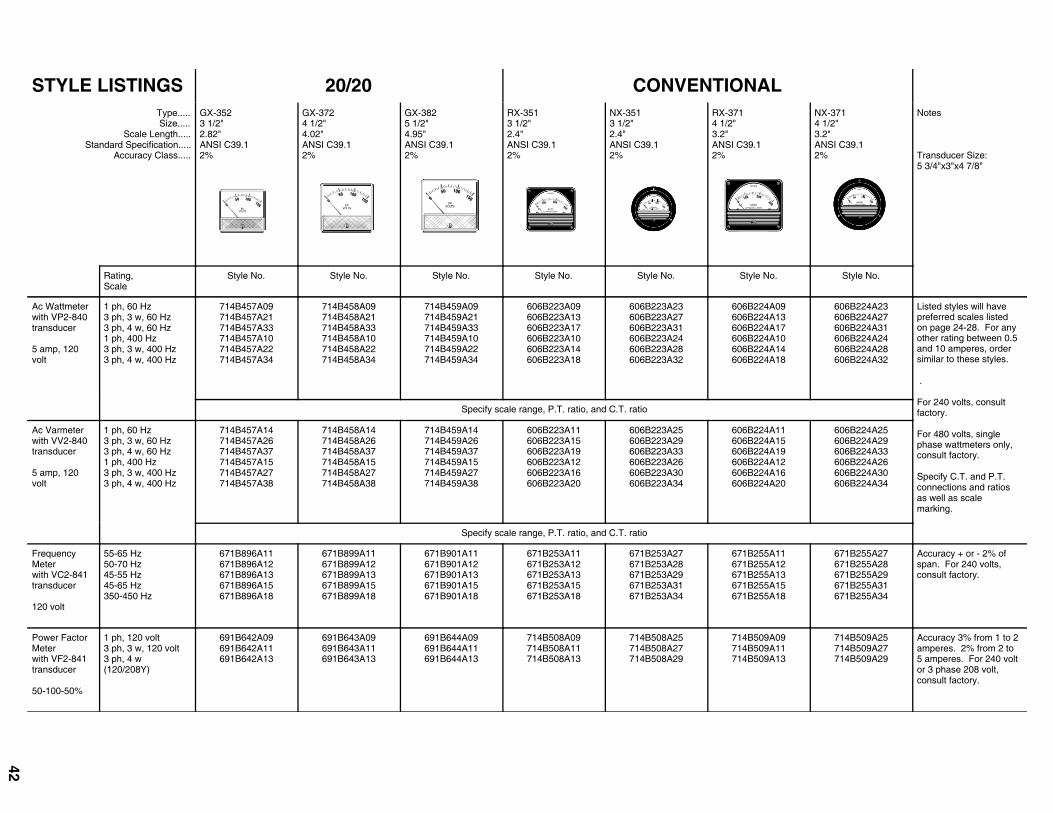
STYLE LISTINGS 20/20 CONVENTIONALType.....Size.....
Scale Length..... Standard Specification.....
Accuracy Class.....
GX-352 3 1/2"2.82"ANSI C39.1 2%
GX-372 4 1/2"4.02"ANSI C39.1 2%
GX-382 5 1/2"4.95"ANSI C39.1 2%
RX-351 3 1/2"2.4"ANSI C39.1 2%
NX-351 3 1/2"2.4"ANSI C39.1 2%
RX-371 4 1/2"3.2"ANSI C39.1 2%
NX-371 4 1/2"3.2"ANSI C39.1 2%
Notes
Transducer Size: 5 3/4"x3"x4 7/8"
Rating,Scale
Style No. Style No. Style No. Style No. Style No. Style No. Style No.
Ac Wattmeter with VP2-840 transducer
5 amp, 120 volt
1 ph, 60 Hz 3 ph, 3 w, 60 Hz 3 ph, 4 w, 60 Hz 1 ph, 400 Hz 3 ph, 3 w, 400 Hz 3 ph, 4 w, 400 Hz
714B457A09 714B457A21 714B457A33 714B457A10 714B457A22 714B457A34
714B458A09 714B458A21 714B458A33 714B458A10 714B458A22 714B458A34
714B459A09 714B459A21 714B459A33 714B459A10 714B459A22 714B459A34
606B223A09 606B223A13 606B223A17 606B223A10 606B223A14 606B223A18
606B223A23 606B223A27 606B223A31 606B223A24 606B223A28 606B223A32
606B224A09 606B224A13 606B224A17 606B224A10 606B224A14 606B224A18
606B224A23 606B224A27 606B224A31 606B224A24 606B224A28 606B224A32
Listed styles will have preferred scales listed on page 24-28. For any other rating between 0.5 and 10 amperes, order similar to these styles.
.
For 240 volts, consult factory.
For 480 volts, single phase wattmeters only, consult factory.
Specify C.T. and P.T. connections and ratios as well as scale marking.
Specify scale range, P.T. ratio, and C.T. ratio
Ac Varmeter with VV2-840 transducer
5 amp, 120 volt
1 ph, 60 Hz 3 ph, 3 w, 60 Hz 3 ph, 4 w, 60 Hz 1 ph, 400 Hz 3 ph, 3 w, 400 Hz 3 ph, 4 w, 400 Hz
714B457A14 714B457A26 714B457A37 714B457A15 714B457A27 714B457A38
714B458A14 714B458A26 714B458A37 714B458A15 714B458A27 714B458A38
714B459A14 714B459A26 714B459A37 714B459A15 714B459A27 714B459A38
606B223A11 606B223A15 606B223A19 606B223A12 606B223A16 606B223A20
606B223A25 606B223A29 606B223A33 606B223A26 606B223A30 606B223A34
606B224A11 606B224A15 606B224A19 606B224A12 606B224A16 606B224A20
606B224A25 606B224A29 606B224A33 606B224A26 606B224A30 606B224A34
Specify scale range, P.T. ratio, and C.T. ratio
Frequency Meter with VC2-841 transducer
120 volt
55-65 Hz 50-70 Hz 45-55 Hz 45-65 Hz 350-450 Hz
671B896A11 671B896A12 671B896A13 671B896A15 671B896A18
671B899A11 671B899A12 671B899A13 671B899A15 671B899A18
671B901A11 671B901A12 671B901A13 671B901A15 671B901A18
671B253A11 671B253A12 671B253A13 671B253A15 671B253A18
671B253A27 671B253A28 671B253A29 671B253A31 671B253A34
671B255A11 671B255A12 671B255A13 671B255A15 671B255A18
671B255A27 671B255A28 671B255A29 671B255A31 671B255A34
Accuracy + or - 2% of span. For 240 volts, consult factory.
Power Factor Meter with VF2-841 transducer
50-100-50%
1 ph, 120 volt 3 ph, 3 w, 120 volt 3 ph, 4 w (120/208Y)
691B642A09 691B642A11 691B642A13
691B643A09 691B643A11 691B643A13
691B644A09 691B644A11 691B644A13
714B508A09 714B508A11 714B508A13
714B508A25 714B508A27 714B508A29
714B509A09 714B509A11 714B509A13
714B509A25 714B509A27 714B509A29
Accuracy 3% from 1 to 2 amperes. 2% from 2 to 5 amperes. For 240 volt or 3 phase 208 volt, consult factory.
42

STYLE LISTINGS ELAPSED TIME Notes:
Elapsed Time Type... Size.............
GH-3322 1/2"
GH-3523 1/2"
BH-3513 1/2"
Description Rating Style No. Sytle No. Style No.
Total HoursNon-Reset Type
0-99,999.9 Hours
120 volts, 60 Hz240 volts, 60 Hz*480 volts, 60 Hz120 volts, 50 Hz
671B375A09671B375A10671B375A11671B375A12
671B376A09671B376A10671B376A11671B376A12
291B474A09291B474A11291B474A12291B474A10
Total MinutesNon-Reset Type0-99,999.9 Minutes
120 volts, 60 Hz240 volts, 60 Hz* ...........................
671B375A13671B375A14 ...................
671B376A13671B376A14 ..................
291B927A09 ..................... .....................
Total Hours Reset Type0-9,999.9HoursTotal MinutesReset Type0-9,999.9 Minutes
120 volts, 60 Hz240 volts, 60 Hz*480 volts, 60 Hz120 volts, 50 Hz120 volts, 60 Hz240 volts, 60Hz* ........................
671B375A25671B375A26671B375A27671B375A28671B375A29671B375A30 .....................
671B376A25671B376A26671B376A27671B376A28671B376A29671B376A30 ....................
291B474A17291B474A19291B474A20291B474A18291B927A21 ..................... .....................
* 240 volt units may be operated at 208 volts.
STYLE LISTINGS CONVENTIONAL
YL
E LI
STI
NG
S
CO
NV
EN
TIO
NA
L
Type...... Size....
Scale Arc.....Standard Specification
Accuracy Class
RT-351Rectangular
3 1/2"2.4"
ANSI C39.12%
NT-351Round3 1/2" 2.4"
ANSI C39.12%
RT-371Rectangular
4 1/2 "3.2"
ANSI C39.12%
NT-371Round4 1/2" 3.2 "
ANSI C39.12%
Notes
Rating,Scale Style No. Style No. Style No. Style No.
AmmeterRadioFrequencyType, self-contained
squarelawscale
1 A 1.5 A
2 A3 A5 A
8 A10 A15 A20 A
409C549A09409C549A10409C549A11409C549A12409C549A13
409C549A14409C549A15409C549A16409C549A17
409C549A43409C549A44409C549A45409C549A46409C549A47
409C549A48409C549A49409C549A50409C549A51
409C572A08409C572A09409C572A10409C572A11409C572A12
409C572A13409C572A14409C572A15409C572A16
409C572A43409C572A44409C572A45409C572A46409C572A47
409C572A48409C572A49409C572A50409C572A51
AmmeterRadioFrequencyType, self-contained
linearexpandedscale
1 A 1.5 A
2 A3 A5 A
8 A10 A15 A20 A
409C549A21409C549A22409C549A23409C549A24409C549A25
409C549A26409C549A27409C549A28409C549A29
409C549A55409C549A56409C549A57409C549A58409C549A59
409C549A60409C549A61409C549A62409C549A63
409C572A21409C572A22409C572A23409C572A24409C572A25
409C572A26409C572A27409C572A28409C572A29
409C572A55409C572A56409C572A57409C572A58409C572A59
409C572A60409C572A61409C572A62409C572A63
* scale tosuitthermo-couple
409C549A38 409C549A39 409C572A38 409C572A39 Orderthermocouplefrom sectionbelow
* Ammeter Radio Frequency Type for use with externalthermocouple square law scale
Price includes ammeter and one pair of style number 1337 832 five-foot leads. Instrument andthermocouple must be calibrated as a unit to insure accuracy within + or - 2% of full scale dial marking.
** scale tosuitthermo-couple
409C549A33 409C549A34 409C572A33 409C572A34 Orderthermocouple from sectionbelow
** Ammeter Radio Frequency Type or use with externalthermocouple Linear expanded scale
Price includes ammeter and one pair of style number 1337 832 five-foot leads. Instrument andthermocouple must be calibrated as a unit to insure accuracy within + or - 2% of full scale dial marking.
External
Thermocouple
Air Type forRadio
FrequencyAmmeter
Rating
1 A 1.5 A
2 A3 A5 A8 A
Style No.
878 638878 639878 640878 642878 644878 646
Rating
10 A15 A20 A25 A30 A50 A
Style No.
878 647878 648878 649878 650878 651878 654
CONVENTIONAL Notes:
Type..... . Size....
Scale Arc..... Standard Specification
Accuracy Class
RT-351Rectangular
3 1/2"2.4"
ANSI C39.12%
NT-351 Round3 1/2 " 2.4"
ANSI C39.12%
RT-371Rectangular
4 1/2 "3.2"
ANSI C39.12%
NT-371Round4 1/2" 3.2"
ANSI C39.12%
Rating,Scale Style No. Style No. Style No. Style No.
MilliammeteRadioFrequencyType
square lawscale
10 mA20 mA50 mA
100 mA150 mA200 mA300 mA500 mA800 mA
409C550A09409C550A10409C550A11409C550A12409C550A13409C550A14409C550A15409C550A16409C550A17
409C550A37409C550A38409C550A39409C550A40409C550A41409C550A42409C550A43409C550A54409C550A55
409C571A08409C571A09409C571A10409C571A11409C571A12409C571A13409C571A14409C571A15409C571A16
409C571A37409C571A38409C571A39409C571A40409C571A41409C571A42409C571A43409C571A54409C571A55
MilliammeteRadioFrequencyType
linearexpandedscale
10 mA20 mA50 mA
100 mA150 mA200 mA300 mA500 mA800 mA
409C550A23409C550A24409C550A25409C550A26409C550A27409C550A28409C550A29409C550A30409C550A31
409C550A51409C550A52409C550A53409C550A54409C550A55409C550A56409C550A57409C550A58409C550A59
409C571A23409C571A24409C571A25409C571A26409C571A27409C571A28409C571A29409C571A30409C571A31
409C571A51409C571A52409C571A53409C571A54409C571A55409C571A56409C571A57409C571A58409C571A59
43

Transformer & LTC Temperature Monitors
Extend Transformer Life & Reduce Maintenance Costs with Transformer AdvantageII
7 Models for new and existing transformers:
5060
70
80
90
100
40
30
20
10
0
0
F
FLUE GAS
100
80
60
40
20
0Weschler
M
V
D
C
Single, dual and three channel analog gauge replacements
Oil, winding, LTC and ambient temperature indication
Three calculated winding temperatures
Rugged NEMA 4X metal case
Auxilliary analog and digital inputs
Multistage fan/pump control, alarm & DNP3.0 capabilities
Combine Digital Precision & Analog Trend Indication
Digital BarGraph Meters
Circular & edgewise styles from 4” to 12”
Red, green, amber & tri-color displays
Measure AC/DC V, A, W, VARs, PF, f, RPM, temperature & more
Single & dual channel replacements for analog gauges
Optional setpoint, alarm, control & SCADA outputs
NEW
NEW
WESCHLER
INSTRUMENTSDIVISION OF HUGHES CORPORATION
65 Years of Power and Process Measurements
Digital panel meters
Analog meters
Portable & specialty meters
Transducers & shunts
Sensors & signal conditioners
Process calibrators
Test instrumentation
Measurement, Control & Test
16900 FOLTZ PARKWAY . CLEVELAND, OH 44149
Phone: (440) 238-2550
Fax: (440) 238-0660
www.weschler.com
e-mail: [email protected]
Complete meter modification center
Products from over 55 leading manufacturers: