fast reconstruction of three-dimensional images in fresnel transform imaging technique using optical...
TRANSCRIPT

Fast Reconstruction of Three-Dimensional Images in Fresnel
Transform Imaging Technique Using Optical Imaging System
Satoshi Ito, Shingo Kawaharada,* Yoshitsugu Kamimura, and Yoshifumi Yamada
Faculty of Engineering, Utsunomiya University, Utsunomiya, 321-8585 Japan
SUMMARY
In this paper, a fast reconstruction of three-dimen-sional images, based on the analogy between the expressionfor the NMR signal in the three-dimensional Fresnel trans-form NMR imaging and the expression for light diffraction,is presented. When three-dimensional imaging is applied toMRI, the problem arises that the computation time forreconstruction is too long, due to the large amount of data.However, the reconstruction time for the spatially continu-ous cross-sectional images can be greatly reduced by high-speed optical operation if the signal is sent to aliquid-crystal spatial light modulator as a set of Fresnelhologram signals, to be displayed continuously and illumi-nated by coherent light. In this study, holographic recon-struction is applied to image reconstruction inthree-dimensional Fresnel transform imaging, and an at -tempt is made to improve the speed of image reconstructionby high-speed transfer of the obtained signals to the holo-graphic reconstruction system as a set of Fresnel holo-grams. Thus, the MR cross-sectional image is reconstructedwith the video rate from the three-dimensional signal data.© 2002 Wiley Periodicals, Inc. Syst Comp Jpn, 33(5):21�29, 2002; Published online in Wiley Interscience(www.interscience.wiley.com). DOI 10.1002/scj.1124
Key words: MRI; three-dimensional image; fastreconstruction; Fresnel transform; holography.
1. Introduction
In current practical applications of MRI, a methodcalled two-dimensional Fourier transform imaging, pro-posed by Kumar�s group at the Swiss Federal Institute ofTechnology [1], is widely used. The method encodes spatialinformation in the amplitude and phase of the NMR signal,using two gradient magnetic fields called phase encodingand reading, and then reconstructs the image using a two-dimensional Fourier transform. Two-dimensional Fouriertransform imaging is widely used at present, since imagedistortion is reduced and the resolution is uniform over thecross section, which are properties suited to NMR imaging.In addition, by applying phase encoding in two directions,the method can easily be extended to three-dimensionalFourier transform imaging.
The authors have proposed Fresnel transform imag-ing [2�4], which is a method of acquiring the NMR signalusing a quadratic nonlinear magnetic field gradient. Thisimaging scheme can also be extended to three-dimensionalimaging by scanning the nonlinear gradient magnetic fieldfor phase encoding in two directions, as in the case ofFourier transform imaging. In general, three-dimensionalimaging can theoretically realize a much higher SN ratiothan two-dimensional imaging, but it has the problem thatthe computation time in the image reconstruction is in-
© 2002 Wiley Periodicals, Inc.
Systems and Computers in Japan, Vol. 33, No. 5, 2002Translated from Denshi Joho Tsushin Gakkai Ronbunshi, Vol. J84-D-II, No. 2, February 2001, pp . 400�407
*Now affiliated with Fuji Xerox Co.
Contract grant sponsor: Supported in part by a Science Grant from theMinistry of Education [Basic study (B) 09558112] 1997�1998.
21

creased due to the very large number of steps needed in dataacquisition.
As a means of remedying the problem of reconstruc-tion time, this study applies holographic reconstruction [5]to three-dimensional image reconstruction. It is noted thatthe expression for the NMR signal obtained by Fresneltransform imaging has the same form as the expression forlight diffraction. Consequently, by using an electronicallywritable liquid-crystal spatial light modulator (LC-SLM)as the hologram display unit, on-line image reconstructioncan be realized by a coherent optical system [6, 7].
A problem in holographic reconstruction when ap-plied to ordinary Fourier transform imaging is that thequality of the reconstructed image is degraded due to theextremely large signal dynamic range [8]. It has been shown[7] that the problem can be remedied by phase-scrambledFourier transform imaging using the nonlinear gradientmagnetic field [9]. Theoretical and experimental studiesdirected at a real-time reconstruction technique have beencontinuing [10].
In this study, the high speed of holographic recon-struction is utilized in the cross-sectional image reconstruc-tion of three-dimensional data. In order to improve thespeed of image reconstruction by applying the holographicreconstruction system to image reconstruction in three-di -mensional Fresnel transform imaging, the signals mustrepresent the hologram of each cross section when the dataacquisition is completed.
For that purpose, this study uses Fourier transformimaging in the frequency reading direction, and the one-di -mensional Fourier transform is applied immediately afteracquisition of the echo signal, so that the signals form ahologram set specifying the cross-sectional images whensignal acquisition is completed. By this method, the cross-sectional images can be reconstructed with high speed fromthe three-dimensional data by transferring the hologram setto the holographic reconstruction system with the videorate. By applying phase-scrambled Fourier transform im-aging with a nonlinear magnetic field gradient, the pro-posed method can also be used in Fourier transformimaging.
2. Three-Dimensional Fresnel Transform
Imaging
2.1. Generation of nonlinear magnetic field
gradient
In Fresnel transform imaging, a nonlinear magneticfield gradient with magnetic intensity of quadratic shape isused [2]. In order to generate such a magnetic field, theparallel rectangular column coil shown in Fig. 1 is used.The behavior of the magnetic field is given by
Here, b is a constant determined by the size of the parallelrectangular column coil, the number of ampere-turns, andso on, and (x′, y′) is the central coordinate of the nonlinearmagnetic field gradient.
It is evident from Eq. (1) that the magnetic fieldintensity does not depend on z, and that the contours of themagnetic field form a cylinder parallel to the z axis, with(x′, y′) as the center. By varying the current flowing in thescanning coil outside the parallel rectangular coil, the posi-tion of (x′, y′) can be shifted (scanned) arbitrarily. Byscanning the position in the x and y directions, the spatialinformation is encoded. For simplicity, the scanning coil forthe y direction is not shown in Fig. 1.
2.2. NMR signal in three-dimensional Fresnel
transform imaging
Figure 2 shows the pulse sequence of three-dimen-sional Fresnel transform imaging using a nonlinear mag-netic field gradient. Figure 2 is interpreted as follows. Astrong RF pulse excites the whole spins in a sample. Thenonlinear magnetic field gradient ∆B is impressed for timeτ. Then, the magnetic field is switched to the linear mag-netic field gradient −Gz in the z direction. The gradient echosignal appearing when the linear magnetic field gradient inthe z direction is reversed is sampled as the data.
By iterating the above procedure with an interval TRfor recovery of the magnetization, while shifting the center(x′, y′) of the nonlinear magnetic field gradient, the signalshown in Eq. (2) is obtained as a function of x′, y′ and thesampling time t [3]:
Fig. 1. Coil configuration for generating the quadraticnonlinear field gradient and scanning coil to move the
center position of the quadratic nonlinear field gradient in the x-direction.
(1)
(2)
22

Here, ρ(x, y, z) represents the spin density distribution ofthe sample. γ is the magnetogyric ratio, τ is the nonlinearmagnetic field gradient impression time, and β is a constantdetermined by the static magnetic field offset. t is the timeafter reversal of the magnetic field gradient, and the originof the time t is set at the center of the gradient echo signal.Equation (2) is the expression for the Fresnel transform inthe x and y directions, and the Fourier transform in the z
direction.
3. Principle of Holographic Reconstruction
3.1. Fresnel hologram
Optical holography is a technique in which the opti-cal information of the object is recorded and restored byutilizing light interference and diffraction. It differs com-pletely from the conventional photography [11]. In opticalholography, when the reference light R and the object lightO interfere with each other, the hologram Hopt is given byEq. (4) [12]:
where R* and O* are the complex conjugate counterparts ofR and O, respectively.
The first and second terms of Eq. (4) correspond tothe intensities of the original object light and the reference
light, respectively. Since these terms are not concerned withthe image reconstruction, they can be replaced by a constantterm K as in Eq. (5). The second term in Eq. (5) containsinformation concerning the object light and its complexconjugate light. Consequently, by illuminating the holo-gram recording these lights with the reproducing light, theobject light and its complex conjugate light can be restored.
Equation (2) has the form of the Fresnel transform inthe x and y directions, and the Fourier transform in the z
direction. Forming the Fourier transform of Eq. (2) withregard to the time t, we obtain
Here, V(x′, y′, ω) is the Fourier transform of v(x′, y′, t) withrespect to time t. We set
The integral expression of Eq. (6) is the Fresnel transformof ρ(x, y, − ω /γGz) with regard to x and y. It should also benoted that Eq. (6) has the same form as the Fresnel diffrac-tion of light and sound waves. ejβx′ corresponds to theinterference by the planar reference wave R*. Since Eq. (6)corresponds to R*O in Eq. (5), the NMR Fresnel hologramHNMR is given by
Here, K′ is a constant, which is set so that Eq. (8) alwaystakes a positive value. It is seen from Eq. (8) that by definingK′ so that the real part of the signal V is always positive, andrepresenting the expression by a two-dimensional gray-level distribution, the result corresponds to a Fresnel holo-gram.
3.2. Holographic reconstruction system
Figure 3 shows the holographic reconstruction sys-tem for reconstruction of an optical image in three-dimen-sional Fresnel transform imaging. The HNMR of crosssections in the z direction represented by Eq. (8) is sent tothe liquid-crystal spatial light modulator (LC-SLM) as thevideo signal. Then, the hologram is displayed on the LC-SLM. If we illuminate the hologram displayed on theLC-SLM with collimated laser light, the transmitted lightcontains the diverging light, the converging light, and thedirect transmitted light.
Fig. 2. Pulse sequence for three-dimensional Fresneltransform imaging technique.
(3)
(4)
(5)
(6)
(7)
(8)
23

By setting the viewpoint for the diverging light, theobject can be viewed through the hologram. The converginglight gives the image focused at the focal distance zr givenby Eq. (9), as seen from the theory of a Fresnel zone plate:
Here, N∆xi is the scanning width of the nonlinear gradientmagnetic field, d is the size of the hologram, and λ is thewavelength of the laser light.
3.3. Acceleration of image reconstruction
After acquiring the NMR signal, there must be awaiting time for magnetization recovery. If the Fouriertransform is applied to the acquired one-dimensional signalduring this waiting time, the image component in the z
direction can be decomposed. At the time when the acqui-sition of the three-dimensional imaging data is completed,the signal corresponding to the Fresnel hologram repre-sented by Eq. (6) is obtained, being decomposed accordingto the z coordinate.
By transferring the above set of Fresnel holograms toan LC-SLM at high speed, and applying the three-dimen-sional holographic reconstruction, spatially continuouscross-sectional images can be reconstructed from the three-dimensional imaging signals at very high speed. By takinga picture of the reconstructed image with a CCD camera,for example, the image can be input to a computer throughthe video capture interface.
Figure 4 is a timing chart, in which the time neededfor the three-dimensional reconstruction is compared to thetimes needed in the Fresnel transform computer reconstruc-tion and the Fourier transform reconstruction. The com-puter reconstruction time in three-dimensional Fourier
transform imaging is approximately 60% of the computa-tion time of three-dimensional Fresnel transform imaging,since quadratic phase modulation is not required before theFourier transform.
In the proposed method, the image can be restoredwhen data acquisition is completed, which greatly im-proves the speed. The time needed for reconstruction of theoptical image itself is determined by the propagation timeof the light, and is on the order of 10�9 s, regardless of thematrix size. Consequently, the time needed to reconstructthe whole three-dimensional image is determined by thehologram process of Eq. (8), the speed of hologram imagedisplay, and the image data transfer. The VGA video signalprocessor used in image data transfer had a transfer per-formance of 60 frames/s. Consequently, if the matrix sizeis within the number of LC-SLM pixels, a reconstructionperformance of 60 frames/s is realized regardless of thematrix size.
4. Method and Experimental Setup
4.1. Configuration of MRI system
Figure 5 shows the configuration of the MRI systemused in the experiment. The MRI system can be divided intothe magnet, the transmitter/receiver, and the computer. Thepulse generator and the data acquisition unit are both de-signed in accordance with CAMAC specifications. An ar-bitrary pulse program can be generated by the computer.The CAMAC system is composed of the crate, the cratecontroller, and the module, as shown in Fig. 5 [13].
The signal flow for the reconstruction of the MRimage is as follows. The RF pulse needed to producenuclear magnetic resonance is sent to the probe coil fromthe transmitter (RF OSC) according to a gate pulse from theD-A converter. After the sample is magnetized, phase en-coding pulse generating a nonlinear magnetic field gradient
(9)
Fig. 4. Data processing procedure in three-dimensionalFresnel transform imaging technique.
Fig. 3. Holographic image reconstruction system inthree-dimensional Fresnel transform imaging technique.
24

is applied. Then, the NMR signal appearing at the reversalof the magnetic field gradient is sampled as the data.
The signal is amplified (RF Amp) and detected(PSD). It is digitized by an A-D converter, and is stored ina transient memory register. The stored digital data aretransferred to the computer and HNMR is produced from thedata. The result is displayed on the LC-SLM. As the mag-net, an air-cored resistive solenoid with a static magneticintensity of 0.0192 T (resonant frequency is f0 = 819 kHz)is used. The computer used in the experiment is IBMPC-compatible with Windows 98 as OS.
4.2. Configuration of holographic
reconstruction system
In the holographic reconstruction system, a He-Nelaser with an output power of 5.0 mW and a wavelength of6328 Å is used as the light source, and a red liquid-crystalpanel with a liquid-crystal projector (Fuji Xerox XP700X)is used as the LC-SLM. Table 1 gives the specifications ofthe LC-SLM and Fig. 6 shows its appearance. The LC-SLM
is used as the amplitude modulator for the incident light. Inthe experiment, the direct transmitted component of thelight transmitted through the LC-SLM is eliminated byoptical filtering, since it does not contribute to the imagecomponent.
4.3. Experiment
The signal data of the three-dimensional Fresneltransform imaging were acquired, and the three-dimen-sional holographic image reconstruction system was usedfor reconstruction of the obtained data. For comparison,computer reconstruction processing was also performed. Aboiled egg and a lotus root were used as the samples forimaging, as in Fig. 7, since the structure is clear and animage with a high SN ratio is obtained by ultralow magneticfield MRI.
Table 2 lists the experimental conditions for three-di-mensional Fresnel transform imaging. After acquiring thesignal, the one-dimensional Fourier transform was applied.The computation time needed to execute the one-dimen-sional Fourier transform was 0.12 ms. The time needed to
Fig. 5. 0.0192-T MR imaging system used in theexperiments.
Table 1. Specifications of LC-SLM
Liquid crystal driving P-Si TFT active matrix
Panel size 1.3 inches
Number of pixels 1024 (H) × 768 (V)
Pixel pitch 25 µm × 24 µm
Constant ratio 1:350
Data source VGA
Fig. 6. LC-SLM used in the experiments.
Fig. 7. Samples used in the experiments.
25

calculate the HNMR by Eq. (8), after acquiring all of the data,was 116 ms. Then, the hologram data were sent at a transferrate of 50 ms/frame and the image was reconstructed.
5. Experimental Results and Discussion
Figures 8 to 10 show the results of imaging experi-ments for samples (a) and (b). The images in Fig. 8 are theFresnel holograms for samples (a) and (b), respectively, atpositions z = �0.2 cm and z = 0.1 cm. The reconstructedimages in Figs. 9 and 10 are five images extracted from 64cross-sectional images with a resolution of 0.1 cm in the zdirection, at intervals of 0.8 and 0.6 cm, respectively. Theupper is the computer reconstructed image, and the loweris the optically reconstructed image.
The computer reconstructed image has a small com-posing matrix of 64 × 64, and the data in the image spaceare interpolated by zero filling in the frequency domain foreasier observation. The optically reconstructed image isobtained by taking the image projected on the screen by aCCD camera. A liquid-crystal panel contained in a com-
mercial video projector is used in the experiment, and isoperated as the amplitude modulator by adjusting the po-larization direction.
In this experiment, the optically reconstructed imagethat was obtained had almost the same quality as the com-puter reconstructed image. It should be noted, however, thatthe computer reconstructed image obtained in this imagingexperiment has high contrast as well as low resolution and
Table 2. Experimental conditions of imaging
Data matrix Nx × Ny × Nz 64 × 64 × 64
Nonlinear magnetic fieldgradient impression time τ
10 ms
Sampling interval ∆t 1 ms
Repetition time TR 100 ms
Imaging parameter γbτ 3.3 rad/cm2
Scanning step ∆x′, ∆y′ 0.1 cm
Resolution ∆x, ∆y, ∆z 0.16 cm, 0.16 cm, 0.1 cm
Gray levels of hologram 256
Fig. 8. Fresnel holograms produced by NMR signal.
Fig. 9. Three-dimensional images of boiled egg. (a)Numerically reconstructed images; (b) optically
reconstructed images.
Fig. 10. Three-dimensional images of lotus root. (a) Numerically reconstructed images;
(b) optically reconstructed images.
26
a low SN ratio. Consequently, it may not be adequate forquality evaluation of the optically reconstructed image.
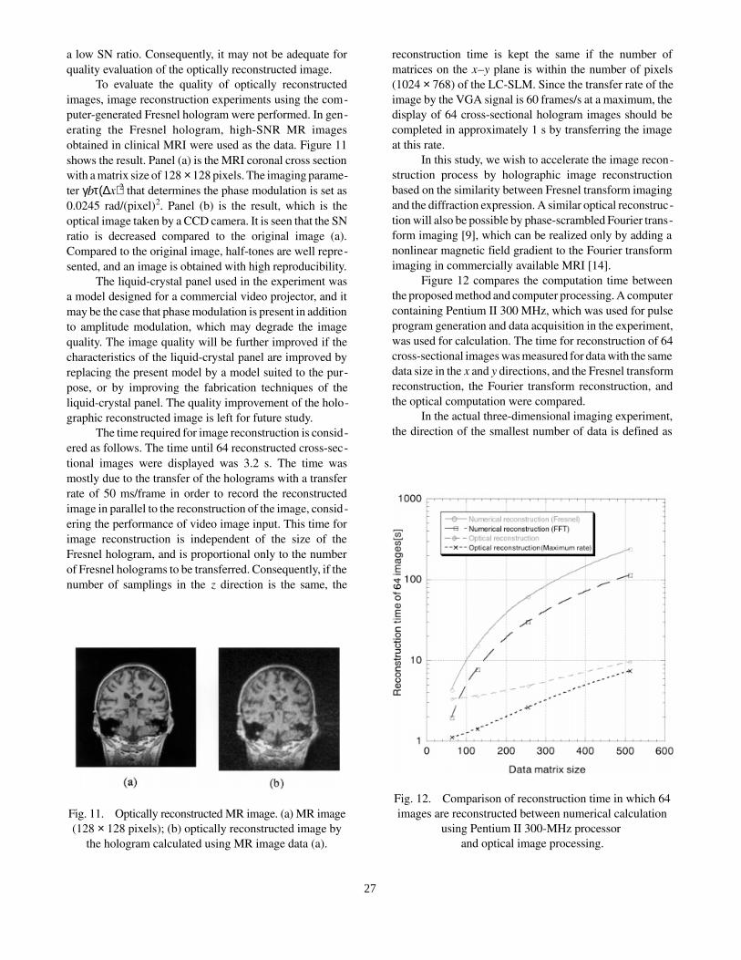
To evaluate the quality of optically reconstructedimages, image reconstruction experiments using the com-puter-generated Fresnel hologram were performed. In gen-erating the Fresnel hologram, high-SNR MR imagesobtained in clinical MRI were used as the data. Figure 11shows the result. Panel (a) is the MRI coronal cross sectionwith a matrix size of 128 × 128 pixels. The imaging parame-ter γbτ(∆x)2 that determines the phase modulation is set as0.0245 rad/(pixel)2. Panel (b) is the result, which is theoptical image taken by a CCD camera. It is seen that the SNratio is decreased compared to the original image (a).Compared to the original image, half-tones are well repre-sented, and an image is obtained with high reproducibility.
The liquid-crystal panel used in the experiment wasa model designed for a commercial video projector, and itmay be the case that phase modulation is present in additionto amplitude modulation, which may degrade the imagequality. The image quality will be further improved if thecharacteristics of the liquid-crystal panel are improved byreplacing the present model by a model suited to the pur-pose, or by improving the fabrication techniques of theliquid-crystal panel. The quality improvement of the holo-graphic reconstructed image is left for future study.
The time required for image reconstruction is consid-ered as follows. The time until 64 reconstructed cross-sec-tional images were displayed was 3.2 s. The time wasmostly due to the transfer of the holograms with a transferrate of 50 ms/frame in order to record the reconstructedimage in parallel to the reconstruction of the image, consid-ering the performance of video image input. This time forimage reconstruction is independent of the size of theFresnel hologram, and is proportional only to the numberof Fresnel holograms to be transferred. Consequently, if thenumber of samplings in the z direction is the same, the
reconstruction time is kept the same if the number ofmatrices on the x�y plane is within the number of pixels(1024 × 768) of the LC-SLM. Since the transfer rate of theimage by the VGA signal is 60 frames/s at a maximum, thedisplay of 64 cross-sectional hologram images should becompleted in approximately 1 s by transferring the imageat this rate.
In this study, we wish to accelerate the image recon-struction process by holographic image reconstructionbased on the similarity between Fresnel transform imagingand the diffraction expression. A similar optical reconstruc-tion will also be possible by phase-scrambled Fourier trans-form imaging [9], which can be realized only by adding anonlinear magnetic field gradient to the Fourier transformimaging in commercially available MRI [14].
Figure 12 compares the computation time betweenthe proposed method and computer processing. A computercontaining Pentium II 300 MHz, which was used for pulseprogram generation and data acquisition in the experiment,was used for calculation. The time for reconstruction of 64cross-sectional images was measured for data with the samedata size in the x and y directions, and the Fresnel transformreconstruction, the Fourier transform reconstruction, andthe optical computation were compared.
In the actual three-dimensional imaging experiment,the direction of the smallest number of data is defined as
Fig. 11. Optically reconstructed MR image. (a) MR image(128 × 128 pixels); (b) optically reconstructed image by
the hologram calculated using MR image data (a).
Fig. 12. Comparison of reconstruction time in which 64images are reconstructed between numerical calculation
using Pentium II 300-MHz processor and optical image processing.
27
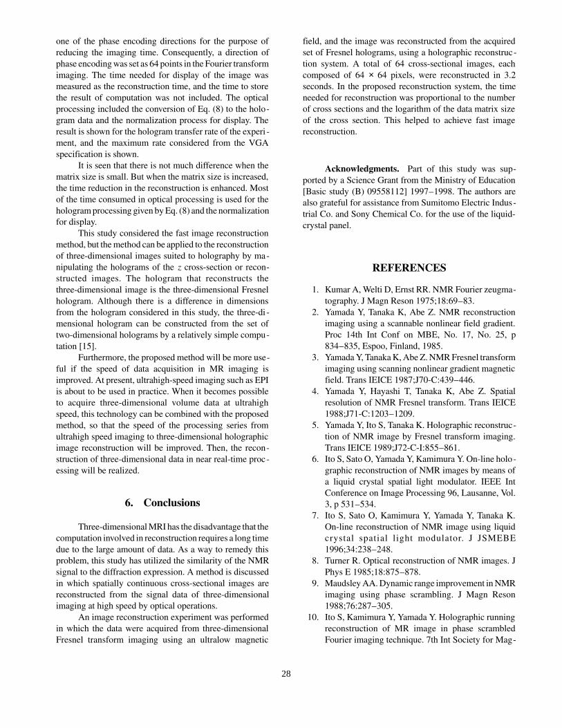
one of the phase encoding directions for the purpose ofreducing the imaging time. Consequently, a direction ofphase encoding was set as 64 points in the Fourier transformimaging. The time needed for display of the image wasmeasured as the reconstruction time, and the time to storethe result of computation was not included. The opticalprocessing included the conversion of Eq. (8) to the holo-gram data and the normalization process for display. Theresult is shown for the hologram transfer rate of the experi -ment, and the maximum rate considered from the VGAspecification is shown.
It is seen that there is not much difference when thematrix size is small. But when the matrix size is increased,the time reduction in the reconstruction is enhanced. Mostof the time consumed in optical processing is used for thehologram processing given by Eq. (8) and the normalizationfor display.
This study considered the fast image reconstructionmethod, but the method can be applied to the reconstructionof three-dimensional images suited to holography by ma-nipulating the holograms of the z cross-section or recon-structed images. The hologram that reconstructs thethree-dimensional image is the three-dimensional Fresnelhologram. Although there is a difference in dimensionsfrom the hologram considered in this study, the three-di -mensional hologram can be constructed from the set oftwo-dimensional holograms by a relatively simple compu-tation [15].
Furthermore, the proposed method will be more use-ful if the speed of data acquisition in MR imaging isimproved. At present, ultrahigh-speed imaging such as EPIis about to be used in practice. When it becomes possibleto acquire three-dimensional volume data at ultrahighspeed, this technology can be combined with the proposedmethod, so that the speed of the processing series fromultrahigh speed imaging to three-dimensional holographicimage reconstruction will be improved. Then, the recon-struction of three-dimensional data in near real-time proc-essing will be realized.
6. Conclusions
Three-dimensional MRI has the disadvantage that thecomputation involved in reconstruction requires a long timedue to the large amount of data. As a way to remedy thisproblem, this study has utilized the similarity of the NMRsignal to the diffraction expression. A method is discussedin which spatially continuous cross-sectional images arereconstructed from the signal data of three-dimensionalimaging at high speed by optical operations.
An image reconstruction experiment was performedin which the data were acquired from three-dimensionalFresnel transform imaging using an ultralow magnetic
field, and the image was reconstructed from the acquiredset of Fresnel holograms, using a holographic reconstruc-tion system. A total of 64 cross-sectional images, eachcomposed of 64 × 64 pixels, were reconstructed in 3.2seconds. In the proposed reconstruction system, the timeneeded for reconstruction was proportional to the numberof cross sections and the logarithm of the data matrix sizeof the cross section. This helped to achieve fast imagereconstruction.
Acknowledgments. Part of this study was sup-ported by a Science Grant from the Ministry of Education[Basic study (B) 09558112] 1997�1998. The authors arealso grateful for assistance from Sumitomo Electric Indus-trial Co. and Sony Chemical Co. for the use of the liquid-crystal panel.
REFERENCES
1. Kumar A, Welti D, Ernst RR. NMR Fourier zeugma-tography. J Magn Reson 1975;18:69�83.
2. Yamada Y, Tanaka K, Abe Z. NMR reconstructionimaging using a scannable nonlinear field gradient.Proc 14th Int Conf on MBE, No. 17, No. 25, p834�835, Espoo, Finland, 1985.
3. Yamada Y, Tanaka K, Abe Z. NMR Fresnel transformimaging using scanning nonlinear gradient magneticfield. Trans IEICE 1987;J70-C:439�446.
4. Yamada Y, Hayashi T, Tanaka K, Abe Z. Spatialresolution of NMR Fresnel transform. Trans IEICE1988;J71-C:1203�1209.
5. Yamada Y, Ito S, Tanaka K. Holographic reconstruc-tion of NMR image by Fresnel transform imaging.Trans IEICE 1989;J72-C-I:855�861.
6. Ito S, Sato O, Yamada Y, Kamimura Y. On-line holo-graphic reconstruction of NMR images by means ofa liquid crystal spatial light modulator. IEEE IntConference on Image Processing 96, Lausanne, Vol.3, p 531�534.
7. Ito S, Sato O, Kamimura Y, Yamada Y, Tanaka K.On-line reconstruction of NMR image using liquidcrystal spatial l ight modulator. J JSMEBE1996;34:238�248.
8. Turner R. Optical reconstruction of NMR images. JPhys E 1985;18:875�878.
9. Maudsley AA. Dynamic range improvement in NMRimaging using phase scrambling. J Magn Reson1988;76:287�305.
10. Ito S, Kamimura Y, Yamada Y. Holographic runningreconstruction of MR image in phase scrambledFourier imaging technique. 7th Int Society for Mag-
28

netic Resonance in Medicine, p 97, Philadelphia,1999.
11. Kubota T. Introduction to holography. AsakuraShoten Co.; 1995.
12. Stroke GW. An introduction to coherent optics andholography. Academic Press; 1969.
13. Toyo Technica Co. Instruction of IEEE-583BUSCAMAC. 1997.
14. Ito S, Kamimura Y, Yamada Y. On-line holographicreconstruction of NMR image using liquid crystalspatial light modulator. Trans IEICE 1998;J81-D-II:184�193.
15. Lohmann AW. Three-dimensional properties ofwave-fields. Optik 1978;51:105�117.
AUTHORS (from left to right)
Satoshi Ito (member) graduated from the Department of Electrical Engineering of Utsunomiya Universi ty in 1987 andcompleted the electrical course at the Graduate School of Engineering in 1989. He then joined Toshiba Corporation. He becamean assistant in the Department of Information Science of Utsunomiya University in 1994. H is research interests are new NMRimaging method, holographic reconstruction, and medical image processing. He is a member of JSMEBE, JMRM, and theOptical Society of Japan.
Shingo Kawaharada (nonmember) graduated from the Department of Information Science of Utsunomiya Universi tyin 1997 and completed the information science course at the Graduate School of Engineering in 1999. He then joined Fuji XeroxCo.
Yoshitsugu Kamimura (member) graduated from the Department of Electrical Engineering of Nagoya University in1980 and completed the doctoral program in 1985. He then joined the Ministry of Posts and Telec ommunications. He becamea lecturer in the Department of Information Science of Utsunomiya University in 1991 and a n associate professor in 1994. Hisresearch interests are NMR measurements of deep body temperature and biological electroma gnetic environment. He holds aD.Eng. degree. He received a Shinohara Encouragement Award in 1988 from IEICE. He is a revie wer for IEICE, and a memberof IEEJ, JSMEBE, the Biophysics Society of Japan, the Japan Society of Health Physics (a member of the planning committee),the Japan Society of Hyperthermic Oncology Society, and IEEE.
Yoshifumi Yamada (member) completed the doctoral program (electrical and information engineering) at Toh okuUniversity in 1971 and then joined the Faculty of Engineering. In 1974, he became a lecturer at Hokkaido University. He movedto Utsunomiya University, becoming an associate professor in the Department of Electric al Engineering in 1979 and a professorin the Department of Information Science in 1990. His research interests are medical info rmation processing, new NMR imagingmethod, and optical reconstruction of NMR images. He holds a D.Eng. degree. He is a member o f JSMEBE, the Society ofInstrumentation and Control Engineers, JSMRM, IEEE, and ISMRM.
29