fast s[si micro adapter - mirror service · 2016-05-08 · 111-.--____ _ introduction this section...
TRANSCRIPT

Technical Reference Manual
81-646 fAST S[SI MICRO [HANNEL
HOST ADAPTER
REVISION HISTORY
Revision Change Activity Date
A Release 05/01192
B Release 10/30/92
This device complies with Part 15 of the FCC Rules. Operation is subjectto the following two conditions: (1) this device may not cause harmful interference, and (2) this device must accept any interference received, including interference that may cause undesired operations.
COPYRIGHT © Copyright 1992 BusLogic Inc. All rights reserved.
BusLogic Inc. makes no warranty of any kind with regard to this material, including, but not limited to, the implied warranties of merchantability and fitness for a particular purpose. BusLogic is not liable for any errors contained herein or incidental or consequential damages in connection with furnishing, performance or use of this material.
. This document contains proprietary information which is protected by copyright. All rights are reserved. No part of this document may be photocopied, reproduced or translated to another language without prior written consent of BusLogic Inc.
TRADEMARKS Company and product names are trademarks or registered trademarks of their respective companies.

TABLE OF CONTENTS
Preface
Section 1: Introduction Product Overview .................................................................................................. 1-1 BT-646 Architecture ............................................................................................... 1-2
Bus Master DMA Controller ......................................................................... 1-3 Advanced SCSI Controller ............................................................................ 1-3 Microprocessor Unit (MPU) .......................................................................... 1-4 Local BIOS PROM .......................................................................................... 1-4
Specifications .......................................................................................................... 1-4 Hardware and Software Requirements .............................................................. 1-5
Hardware ......................................................................................................... 1-5 Software ........................................................................................................... 1-5
Reference Documents ............................................................................................ 1-5
Section 2: Unpacking and Installation Unpacking and Installation .................................................................................. 2-1 Installation Tools .................................................................................................... 2-2 Configuration Instructions ................................................................................... 2-2
General ............................................................................................................. 2-2 Host Adapter Integration ..................................................................................... 2-2
Device Termination ........................................................................................ 2-2 Cabling Requirements ................................................................................... 2-3 SCSI Device ID Selection ............................................................................... 2-3 Disk Drive Power Connector ........................................................................ 2-4
Installing the BT-646 .............................................................................................. 2-4 Micro Channel Configuration Settings ............................................................... 2-6 Hard Disk Initialization ...................................................................................... 2-11
Set-up, Initialization and Partitioning Procedure .................................... 2-11 Warranty Information ......................................................................................... 2-14
Section 3: Electrical Interface Micro Channel System Bus Electrical Interface ................................................. 3-1
Summary of Micro Channel Signals ............................................................ 3-2 PI Input/Output Signal Descriptions ......................................................... 3-6
SCSI Bus Electrical Interface ............................................................................... 3-11 SCSI Electrical/Physical ....................................... : ...................................... 3-11 SCSI Signal Interface .................................................................................... 3-13 SCSI Signal Definitions ................................................................................ 3-15
iii

iv
TABLE OF CONTENTS CONTINUED
Section 4: Hardware Description Host DMA Data Transfer Control ....................................................................... 4-1 Hardware Control Registers ................................................................................ 4-1
Control Register (Write Only) I/O Base Address + 0 ............................... 4-2 Status Register (Read Only) I/O Base Address + 0 ................................... 4-3 Command/Parameter Register (Write Only) I/O Base Address + 1 .... .4-5 Data In Register (Read Only) I/O Base Address + 1 ................................. 4-6 Interrupt Register (Read Only) I/O Base Address + 2 ............................. 4-7
Reset Operations .................................................................................................. 4-10 Micro Channel Host Initiated Reset Operation ........................................ 4-10 SCSI Bus Reset Operations .......................................................................... 4-11 SCSI Bus Soft Reset Option ......................................................................... 4-12 SCSI Bus Hard Reset Option ....................................................................... 4-12
Section 5: Software Interface Bus Master Direct Memory Access (DMA) ........................................................ 5-2
DMA Compatibility Mode ............................................................................ 5-2 DMA Extended Mode .................................................................................... 5-3
Interrupt Processing .............................................................................................. 5-4 Host Adapter Commands .................................................................................... 5-5 Mailbox Commands ............................................................................................ 5-15 Mailbox Initialization .......................................................................................... 5-16 Outgoing Mailbox Structure .............................................................................. 5-17 Incoming Mailbox Structure .............................................................................. 5-17 Host Adapter as Initiator on the SCSI Bus ....................................................... 5-18 Host Adapter in Target Mode ............................................................................ 5-21
Host Adapter Target Mode Operation-CCB Available ........................ 5-22 Host Adapter Target Mode Operation-CCB Not Available ................ 5-22
Command Control Block Structure ................................................................... 5-24 Scatter-Gather Operations .................................................................................. 5-29 BIOS Command Interface ................................................................................... 5-30
BIOS Commands and Input Parameters ................................................... 5-30 BIOS Command Completion Status .......................................................... 5-32
BIOS Disk Commands ........................................................................................ 5-34
Appendix A: BT·646 Internal Diagnostics
Appendix B: 32·Bit Mode Addressing
Appendix C: A List of Acronyms
TABLE OF CONTENTS CONTINUED
List of Figures 1-1. System Architecture ....................................................................................... 1-2 1-2. Host Adapter Architecture ........................................................................... 1-3
2-1. The BT-646 Host Adapter Board .................................................................. 2-1 2-2. SCSI Terminator Configurations .................................................................. 2-3 2-3. Configuration Settings ................................................................................... 2-6
3-1. Connector Rows on the BT-646 Board Edge ............................................... 3-1 3-2. Terminator Power Schematic ...................................................................... 3-12
4-1. Control Register (Write) ................................................................................ 4-2 4-2. Status Register (Read) .................................................................................... 4-3 4-3. Command/Parameter Register (Write) ...................................................... 4-5 4-4. Data In Register (Read) .................................................................................. 4-6 4-5. Interrupt Register (Read Only) ..................................................................... 4-7
5-1. Mailbox Array ............................................................................................... 5-16 5-2. Scatter-Gather ............................................................................................... 5-29
List of Tables 1-1. Physical and Electrical Specifications .......................................................... 1-4
3-1. PI Component Side Row "A" Edge Connector ......................................... 3-2 3-2. PI Solder Side Row "B" Edge Connector ................................................... 3-4 3-3. PI Signal Descriptions ................................................................................... 3-6 3-4. Jl & J2 Single-Ended SCSI Interface Signal Pin Assignments ................ 3-13 3-5. Jl & J2 Differential SCSI Interface Signal Pin Assignments ................... 3-14 3-6. J4 Disk Drive Power Connector Pin Descriptions ................................... 3-14 3-7. Jl & J2 SCSI Interface Signal Descriptions ................................................ 3-15
4-1. BT-646's Hardware Control Registers ......................................................... 4-1
5-1. Host Adapter Commands ............................................................................. 5-5
v

vi

PREFACE
AUDIENCE
SCOPE
CONTENTS
This manual is intended for individuals who will be installing and configuring the BusLogic BT -646 host adapter board in a Micro Channel™ host system. It is also intended for system design engineers interested in designing software drivers for either single or multitasking operating systems.
This manual contains the information an individual needs to unpack, to install, and to configure the BT -646 in a Micro Channel host system. It also contains a complete operational description of the BT-646's hardware control registers. Finally, the manual explains the software interface between the Micro Channel host system and the BT-646.
The information in this manual is divided into five sections and three appendices:
• Section 1 provides a functional description and overview of the BT-646's major components.
• Section 2 contains installation and configuration instructions.
• Section 3 describes the connector pin assignments for the Micro Channel bus, for the SCSI bus, and for the floppy interface.
• Section 4 explains the BT-646's hardware operation.
• Section 5 describes the BT-646's software operation. It explains how the Micro Channel host system and the BT -646 communicate.
• Appendix A discusses the BT-646's internal diagnostics.
• Appendix B describes 32-bit mode addressing.
• Appendix C provides a list of acronyms used in this manual.
Preface I vii

RELATED PUBLICATIONS
• BusLogic's Micro Channel SCSI Host Adapter BT-646 Data Sheet
• BusLogic's Micro Channel SCSI Host Adapter BT -646 Installation Guide
• The Micro Channel installation and set-up guide
• The operating system installation and user's guide
• The Micro Channel computer technical reference manual (optional)
• The installation guide for third-party device drivers (optional)
• Small Computer System Interface, ANSI X3.131-1986 American National Standards (optional).
NOTATIONAL CONVENTIONS
The following conventions are used throughout this manual:
Convention Description
UPPERCASE Used to indicate the names of keys.
A hyphen indicates an active low signal.
+ A plus sign indicates an active high signal.
BT-646 The term used to refer inclusively to the BT-646S and BT-646D boards.
viii • Preface

111-.--____ _ INTRODUCTION
This section provides a functional description of the BusLogic BT -646 host adapter. It also supplies an overview of the BT-646's major components.
PRODUCT OVERVIEW
The BusLogic BT -646 host adapter is an intelligent Micro Channel to SCSI bus master host adapter product based on a BusLogic-designed, universal ASIC technology. It provides a high-performance interconnection between the Micro Channel bus and Small Computer System Interface (SCSI) peripheral devices. The BT -646 is designed for multitasking applications such as UNIX'TM, XENIXTM, NetWare™, and OS/2. Already fully supported by these and other popular operating systems, the BT-646 requires no special software drivers. This is because it already provides a superset of the AHA-l646'sTM I/O registers and command protocol at the interface level. A BusLogic-designed bus master controller ASIC, an advanced SCSI controller chip and a 16-bit microprocessor provide higher speed, lower power consumption, fewer parts and higher reliability.
The BT-646 supports a full 32-bit address path and can access up to four Gigabytes of system memory. Thus the total memory supported is limited only by the packaging constraints of the individual product rather than by the system architecture.
Bus master 8-, 16-, or 32-bit data transfers are performed at speeds of up to 40 MBytes/sec on the Micro Channel bus. The BT-646S supports single-ended SCSI drives with asynchronous data rates of up to 7 MBytes/sec and synchronous data rates of up to 10 MBytes / sec with the proper termination and cabling. The BT -646S uses low dropout voltage regulator and 100 ohm resistor to provide active terminationon the SCSI bus. The BT-646D supports differential SCSI drives with asynchronous data rates of up to 7 MBytes / sec and synchronous data rates of up to 10 MBytes/ sec. The BT-646D uses the 330 ohm/ISO ohm/330 ohm resistor sets for the SCSI bus termination. Both internal and externa1S0-pin connectors are included on the board for flexibility in attaching SCSI devices to the system.
Introduction I 1-1

BT·646 ARCHITECTURE
As illustrated in Figure I-I, the BT-646 plugs into a Micro Channel system and supports the attachment of internal SCSI drives or the connection to external SCSI peripheral devices in add-on enclosures.
Internal SCSI Connector
BT-646 ---...,.:;-, PCB
External SCSI Connector
· · · · · · · · · · · · · · · · . . . . . . . •....................
Internal -....-•• -SCSI Hard
Drive
Micro Channel System
Micro Channel CPU
: ~ : . : l(teroCU' • i SCSI i : Drive: ~ I .,. · . · .. · . : : ~' ...... .,...... I,'
............ ;,'
Internal SCSI Drive
BT-646 Host Adapter
Board
External SCSI Drive
Figure 1-1. System Architecture
1-2 • BT-646 Technical Reference Manual

Figure 1-2 is a functional block diagram illustrating the major elements in the BT-646's design. The following paragraphs describe each component. The circled numbers in the text corresponds to the circled numbers in the figure.
MICRO BusLogic BT-646 CHANNEL
HOST SYSTEM
~
Data & Address Lines • BIOS
~ r---Y ROM J2 External SCSI
,..-l Connector M I C R L-J... • • 0
C DMAData ~ ~ H BUSLOGIC SCSI INTERFACE I
Jt A OMABUS CONTROLLER Internal N MASTER COntrol SCSI N Connector E Control Signals L
B
'l MPIJ Control Bus 1~ U s
J il • MPU Local Local
INTEL ROM RAM 80186
'" ;r
Figure 1-2. Host Adapter Architecture
Bus Master DMA Controller
All Micro Channel host bus interface logic is provided on the board by the BusLogicdesigned bus master ASIC O. This chip provides bus master capabilities which greatly reduce the involvement of the host system's CPU in I/O control and data transfer activities. Under control of this chip, 8-,16-, or 32-bit bus master transfers of at up to 40 MBytes/ sec to and from the main system memory are possible with the use of its internal 128-byte FIFO. A true multi-tasking mailbox structure·supports up to 255 tasks. The BT-646 automatically enables and disables the data streaming to match the hardware capability of the motherboard. If the motherboard supports data streaming, the BT -646 will transfer data in streaming mode. If the motherboard does not support data streaming, the BT-646 will transfer data in non-streaming mode. This performance and improved bus utilization significantly enhances mul- ~
titasking and multi-user applications.
Advanced SCSI Controller
On-board control of the interface to SCSI peripheral devices is provided by another ASIC, the advanced SCSI interface controller 8. Up to 10 MBytes/ sec synchronous and 7 MBytes/sec asynchronous SCSI data. transfers are supported by the SCSI interface controller. With this chip, the BT-646 can operate either in an initiator or target role. This low-power, high-performance CMOS component completely conforms to the ANSI standard, X3.131-1986 for the Small Computer System Interface. The chip reduces protocol overhead by performing common SCSI algorithms or sequences in response to a single host command.
Introduction I 1-3
Microprocessor Unit (MPU)
Local BIOS PROM
SPECIFICATIONS
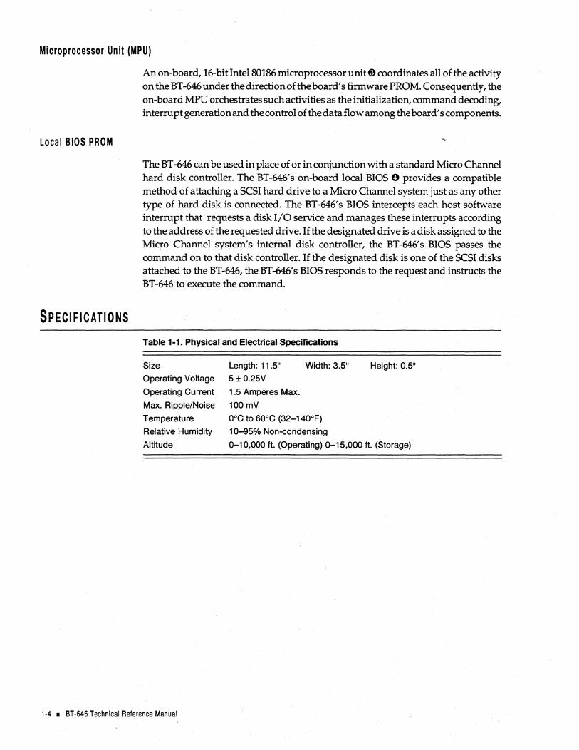
An on-board, 16-bit Intel 80186 microprocessor unit. coordinates all of the activity on the BT -646 under the direction of the board's firmware PROM. Consequently, the on-board MPU orchestrates such activities as the initialization, command decoding, interrupt generation and the control of the data flow among the board's components.
The BT -646 can be used in place of or in conjunction with a standard Micro Channel hard disk controller. The BT-646's on-board local BIOS 0 provides a compatible method of attaching a SCSI hard drive to a Micro Channel system just as any other type of hard disk is connected. The BT-646's BIOS intercepts each host software interrupt that requests a disk I/O service and manages these interrupts according to the address of the requested drive. If the designated drive is a disk assigned to the Micro Channel system's internal disk controller, the BT-646's BIOS passes the command on to that disk controller. If the designated disk is one of the SCSI disks attached to the BT-646, the BT-646's BIOS responds to the request and instructs the BT -646 to execute the command.
Table 1-1. Physical and Electrical Specifications
Size
Operating Voltage
Operating Current
Max. Ripple/Noise
Temperature
Relative Humidity
Altitude
Length: 11.5"
5 ± 0.25V
1.5 Amperes Max.
100 mV
Width: 3.5"
DoC to 60°C (32-140°F)
10-95% Non-condensing
Height: 0.5"
0-10,000 ft. (Operating) 0-15,000 ft. (Storage)
1-4 • BT-646 Technical Reference Manual

HARDWARE AND SOFTWARE REQUIREMENTS
Hardware
Software
The BT-646 can be installed in any Micro Channel compatible computer. To install the BT -646 successfully you must have part or all of the following hardware and software.
Micro Channel computer system with the following:
• One available Micro Channel 16-bit or 32-bit expansion slot
• DC power for an internal 5.25" or 3.5" SCSI drive or an external subsystem with the corresponding D-shell, 50-pin external cable
• One Common Command Set (CCS) SCSI-2 compatible disk drive
• One 50-pin flat ribbon cable to connect internal SCSI devices to the BT-646.
• PC-DOS or MS-DOS
• IBM OS/2 or M5-0S/2
• Interactive Unix or SCO UNIX/XENIX "GT" version
• Novell NetWare 286/386
• Micro Channel configuration diskette
• Included or third-party device drivers for each operating system.
REFERENCE DOCUMENTS
• BusLogic's Micro Channel SCSI Host Adapter BT-646 Data Sheet
• BusLogic's Micro Channel SCSI Host Adapter BT-646 Installation Guide
• The Micro Channel installation and set-up guide
• The operating system installation and user's guide
• The Micro Channel computer technical reference manual (optional)
• The installation guide for third-party device drivers (optional)
• Small Computer System Interface, ANSI X3.131-1986 American National Standards (optional).
Introduction I 1-5

1-6 • BT-646 Technical Reference Manual

11'-----____ _ UNPACKING AND INSTALLATION
This section describes how to unpack, to inspect, to configure, and to install the BT-646S and BT -646D host adapter boards in a Micro Channel host system. It also describes how to initialize the software and set the host adapter options for operation in Micro Channel-compatible systems. Refer to Figure 2-1 for an illustration of the BT -646 board.
UNPACKING AND INSTALLATION
Before handling the BT -646, please take the necessary electro-static discharge precautions. Touch your computer on a metal part to discharge static electricity before handling the board. The board should always be held by the edges even after static electricity is discharged.
While practicing appropriate anti-static precautions, remove the BT -646 from its protective envelope. Verify that no physical damage occurred during shipping by inspecting the board for bent pins, loose parts, broken traces, and chipped or broken connectors.
C> LED
J1 Internal SCSI COnnector
ScSi Interface
COntroller '----'
P1 Edge Connector Pin
Figure 2-1. The BT-646 Host Adapter Board
Unpacking and Installation I 2-1
INSTALLATION TOOLS
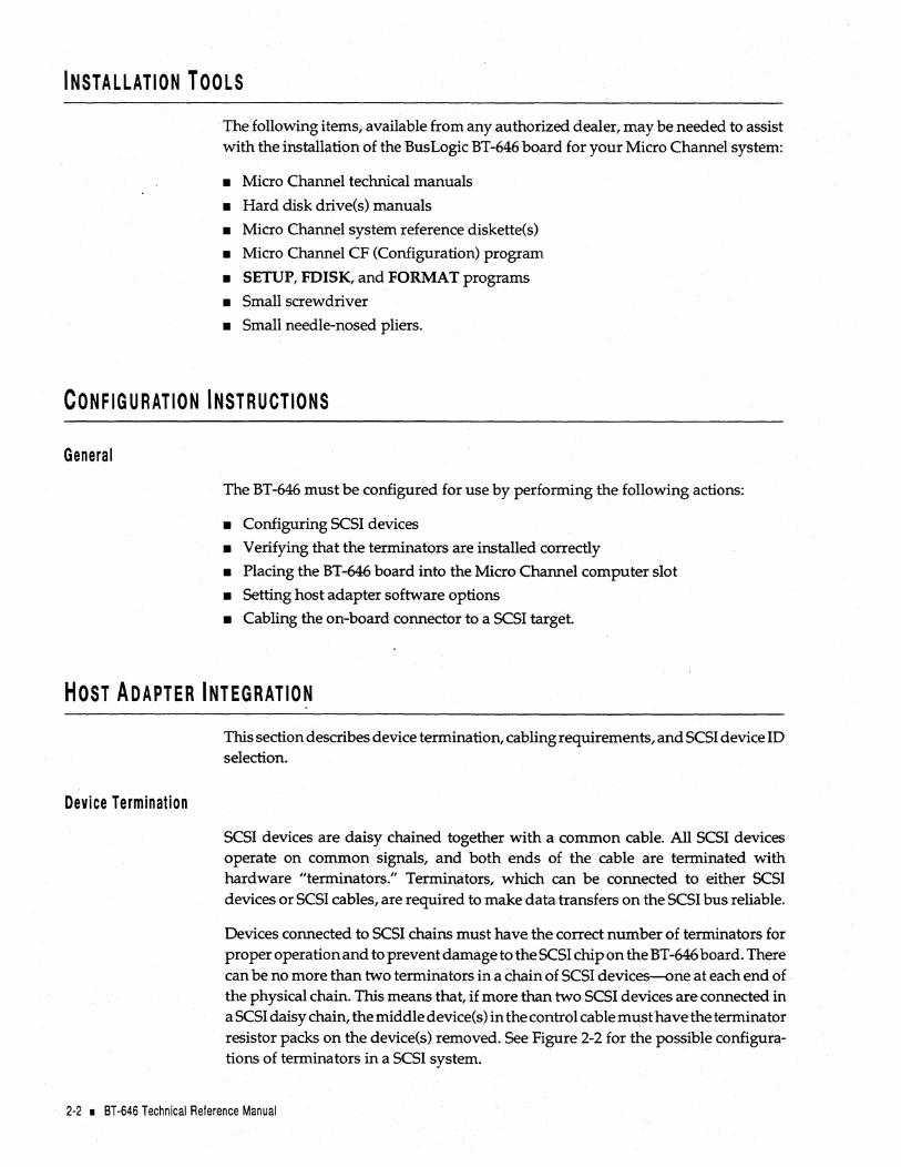
The following items, available from any authorized dealer, may be needed to assist with the installation of the BusLogic BT-646 board for your Micro Channel system:
• Micro Channel technical manuals
• Hard disk drive(s) manuals
• Micro Channel system reference diskette{s)
• Micro Channel CF (Configuration) program
• SETUP, FDISK, and FORMAT programs
• Small screwdriver
• Small needle-nosed pliers.
CONFIGURATION INSTRUCTIONS
General
The BT-646 must be configured for use by performing the following actions:
• Configuring SCSI devices
• Verifying that the terminators are installed correctly
• Placing the BT-646 board into the Micro Channel computer slot
• Setting host adapter software options
• Cabling the on-board connector to a SCSI target.
HOST ADAPTER INTEGRATION
Device Termination
This section describes device termination, cabling requirements, and SCSI device ID selection.
SCSI devices are daisy chained together with a common cable. All SCSI devices operate on common Signals, and both ends of the cable are terminated with hardware "terminators." Terminators, which can be connected to either SCSI devices or SCSI cables, are required to make data transfers on the SCSI bus reliable.
Devices connected to SCSI chains must have the correct number of terminators for proper operation and to prevent damage to the SCSI chip on the BT -646 board. There can be no more than two terminators in a chain of SCSI devices-one at each end of the physical chain. This means that, if more than two SCSI devices are connected in a SCSI daisy chain, the middle device(s) in the control cable must have the terminator resistor packs on the device(s) removed. See Figure 2-2 for the possible configurations of terminators in a SCSI system.
2-2 • 8T-646 Technical Reference Manual

Cabling Requirements
. "I BusLoglc BT-646 a: I Host Adapter ~ I
BusLogic BT-646 il! I Host Adapter ~
BusLogic BT-646 Host Adapter
I
IT R
L: SCSI Device
SCSI Device
SCSI Device
Figure 2-2. SCSI Terminator Configurations
IT SCSI R Device
L:
Selecting the proper SCSI cable for a particular system configuration is of great importance. If two or more SCSI devices are configured in a SCSI daiSY chain, the devices must be connected by a 50-conductor daisy-chain cable.
Before plugging in cable connectors, check that the ""''' mark molded on the connector or the colored stripe on the cable (indicating the location of Pin 1) matches Pin 1 of the connector on the BT-646 board.
SCSI Device ID Selection
The SCSI ID is a number between a and 7 assigned to any SCSI device. The SCSI ID number is used by the computer to communicate with the devices connected to it. All SCSI devices must have a unique SCSI number to identify it on the SCSI chain. A SCSI device is usually fixed as either an initiator or a target, when two or more SCSI devices communicate, but some devices are capable of performing either role. Devices with higher ID numbers have a higher priority in communicating with the computer.
Most SCSI peripheral devices are shipped with a preassigned SCSI ID number. A SCSI ID switch is usually located on the back panel of such devices. Change the SCSI ID of other peripheral devices only as recommended in the owner's manual. Refer to the heading, "Micro Channel Configuration Settings," later in this manual for procedures on how to set the SCSI ID number of the BT-646.
Unpacking and Installation I 2-3

Disk Drive Power Connector
A 4-pin disk drive power connector (J 4) is located at the top edge of the BT -646 board next to the SCSI connector J1. This connector provides standard + 12V and +5V power to disk drives.
Note: The BT -646 brings the 12 volt power supply to the 4-pin powerconnector (J4) via three gold fingers on the edge connector. The power rating of the Micro Channel edge connector on the 12 volt is one ampere per finger. Consequently, the maximum power allowed from the 12 volts (Pin 1 of J4) is three amperes. Because certain large SCSI drives may require more than three amperes when their motors are spinning up, BusLogic recommends that this connector not be connected to these large SCSI drives.
Based on the power rating of the SCSI drives, it is generally recommended that this power connector not be daisy chained to multiple drives.
INSTALLING THE BT ·646 This section describes how to install the BT-646 in a 16-bit or 32-bit slot inside the Micro Channel host system and how to connect it to other devices. Install the BT -646 in your computer by performing the following steps:
1. Remove power from the host system.
2. Referring to the host system owner's manual, open the case to gain access to the motherboard and expansion slots. If the computer has been on, wait a few minutes until the power supply case has cooled down inside the computer. If the power supply case is cold, touch it to discharge any static electricity that may be on your clothes or body. If a disk controller drive board has been installed, remove all connecting cables to the board and then lift it out of the host computer.
SCSI Drive -----''
Card Cage Slot Guides
r---- 50-Pin SCSI Drive Cable
,---- Power Supply
Rear of Micro Channel System
Front of Micro Channel System
2-4 • BT-646 Technical Reference Manual

3. Remove the mounting screw and the existing bracket from the rear panel behind the 16-bit or 32-bit slot that has been selected for insertion of the BT-646. The Micro Channel slot closest to the internal hard drive(s) is the best choice.
4. If the BT -646 will be installed in a host which is not at either end of the SCSI bus, terminators on the board will need to be removed.
For the BT -646S, RP2 and RP3 are the terminators. RP2 and RP3 are resistor packs containing 9 bused 100 ohm resistors.
For the BT-646D, RP6 through RP13 are the terminators. RP6, RPS, RP10, and RP12 are resistor packs containing 5 isolated 150 ohm resistors. RP7, RP9, RP11, and RP13 are resistor packs containing 9 bused 330 ohm resistors.
See the heading, "Host Adapter Integration," in this manual for more information regarding device termination. The BT-646 is shipped with terminators installed.
Connect 50-Pin SCSI Drive Cable to J1 on PCB
Rear of Micro Channel System
Front of Micro Channel System
5. Press the BT-646 downward into the selected 16-bit or 32-bit slot, align the mounting bracket, and reinstall the mounting screw.
Caution: Make sure that the board is properly seated in the slot.
6. Connect the large 50-pin connector within the host computer to the single-ended SCSI connector, J1. Place the connector cable around the power supply and over any other boards. Depending on the configuration of your computer, other types of cables could be used. See the heading, "Cabling Requirements," for details.
7. Verify that all connections are secure.
S. Reattach and close the cover of the host computer as described in the system owner's manual.
Unpacking and Installation I 2-5

MICRO CHANNEL CONFIGURATION SETTINGS
The BT -646 fully supports the Micro Channel automatic configuration facility and is operational with most computers using the default settings in the BT -646 configuration diskette supplied with the board. The host adapter configuration options will need to be changed if conflicting port assignments or memory allocation is encountered. Every BusLogic Micro Channel controller comes with a floppy diskette which contains the BusLogic configuration file (@0708.ADF).
Before starting, perform the following steps:
1. Prepare a back-up copy of the system reference diskette provided with your host computer.
2. Place the back-up system reference diskette in the floppy drive and then reboot your system by pressing the CONTROL, ALTERNATE, and DELETE keys simultaneously ..
3. After the boot is completed, the system's main menu will appear: Select the Copy on Option Diskette command and follow the instructions to copy [email protected] file from the BusLogic-supplied diskette.
4. When the main menu reappears, select the Set Configuration command. Select the Change Configuration command and then follow the directions on your screen to select the BT -646.
The default settings for configuration options as shown on the screen are illustrated in Figure 2-3. Move the cursor to the field desired, press the F5 or F6 keys to scroll through the selections for each option and then leave the field to select the option desired.
Slot 5 - BusLogic BT -646 Micro Channel to SCSI Host Adapter (v1.0)
2-6 • 8T-646 Technical Reference Manual
BIOS Address ...••................. ~ ..••............•...•..••..........•.... [OCOOOh] 1/0 Port Address ..............•.•..................•.......•..•.•....•.•... [330h] Arbitration Level ...............................................•....•....... [LeveL5J Arbitration Fairness ..........•.......•...................•...•...........• [On] Interrupt Request .......................................................... [lnC15J Data Streaming ............................................................. [Disable] Adapter SCSI Bus 10 .................................................... [10J] Adapter Initiate Sync Negotiations ........•....................... [OnJ Adapter SCSI Parity Checking ...................................... [On] Disk> 1 GB and not SCO UNIX ..........•........•.•............. [Off]
Figure 2-3. Configuration Settings

Note: For details on greater than 1 GB drive support, refer to the heading, "Disk> 1 GB and not SCQ UNIX," later in this section.
Before operating the BT-646, verify that the configuration settings have been set according to the target system's operating requirements. The following paragraphs describe the settings for each configuration option.
BIOS Address. The BIOS address resides within the host memory map and is executed by the host even though it is physically located on the BT-646. The BIOS intercepts host interrupt 13H and then dispatches a command to the BT-646 for all host to SCSI disk accesses under the DOS environment. This setting allows you to select the starting address of a 16K Byte memory slot within the host memory space for the BIOS.
If more than one host adapter is installed within the same Micro Channel host system, only one can have the BIOS enabled. The BIOS on each additional host adapter must be disabled. The default setting for this option is DCOOOH.
BIOS Address
DCOOOh Disable D8000h D4000h DOOOOh CCOOOh C8000h
110 Port Address. The host communicates with the BT -646 via the BT -646' s three 1/ a registers. (Refer to Section 4 of this manual for more details on these registers.) This setting lets you define the base I/O address of these three registers within the host I/O map. Note that each board within the same Micro Channel host system must have its unique I/O register addresses to prevent hardware conflicts. The default starting address is 330H.
Host Adapter Configuration I/O Port Address
330h 334h 234h 134h 230h 130h
Unpacking and Installation I 2-7

Arbitration Level. In order for the BT -646 to become a bus master on the Micro Channel bus, it must make a request to start a bus arbitration. Once a request is made, the arbitration cycle is initiated by the central arbiter of the system as soon as the present bus master releases the bus. Among all of the participating arbiters, the one with the highest priority will win control of the channel. This option allows the user to define the arbitration level for the BT-646. Arbitration level 0 has the highest priority and level 7 has the lowest priority. The default setting is levelS.
Arbitration Level
Level_5 Level_6 Level_7 Level_4 Level_3 Level_ 1 Level_O
Arbitration Fairness. In order for the lower priority arbiters to gain control of the channel, the Micro Channel has an arbitration fairness feature. If the arbitration fairness feature is turned off, the arbitrating device that owns the channel may immediately participate in the next arbitration cycle as soon as it releases the channel. If the arbitration fairness feature is turned on, it will not participate in any arbitration cycle until all other requesting devices have been serviced. This option allows you to set the arbitration fairness on or off. The default setting is fairness on.
Interrupt Request. The BT -646 generates a hardware interrupt to the host whenever an interrupt condition exists. (Refer to the description of the Interrupt Register in Section 4 of this manual for details on this register.) You can use this setting to specify the hardware interrupt line on the Micro Channel bus that the BT-646 should use to generate interrupts to the host.
Each selected hardware line is level triggered. Level-triggered interrupts assert interrupts low. Level-triggered interrupts allow multiple boards to share the same hardware interrupt line on the Micro Channel bus. Note that unless the device drivers have the capability of handling shared interrupts, each board in the Micro Channel host system must be assigned a unique hardware interrupt line to prevent conflicts. The default setting for this option is Channel 15
Interrupt Request
Int_15 InU4 InU2 InU1 InUO Ine9
2·8 • 8T·646 Technical Reference Manual

Data Streaming. The streaming data procedure on the Micro Channel bus provides performance improvements over basic transfer procedures for block transfers. Data transfer rates of up to 40 MBytes/sec are supported. The transfer of a data block is supported by using a single address followed by multiple 16 or 32-bit data transfers within a single streaming data cycle. Note, however, that certain motherboards may not support data streaming. This option allows you to enable or disable data streaming based upon the motherboard used. The default setting is to have data streaming disabled.
Oata Streaming
Disable Enable
Adapter SCSI Bus ID. There are eight SCSI IDs (0-7) on a SCSI bus. SCSI ID 7 has the highest priority. Each initiator or target on a SCSI bus must be assigned a unique SCSIID.
This setting enables you to define the SCSIID for the BT -646 on the SCSI bus. Because the BT-646 is an initiator on the SCSI bus dispatching host commands to all SCSI targets on the bus, the default SCSI ID is 7. Note that the BT-646's on-board BIOS requires that your SCSI drives be configured for SCSI ID 0 and 1. This requirement is important only if you intend to boot your system from the BT -646. The as-shipped (default) SCSIID is 7.
SCSI Configuration Adapter SCSI Bus 10
10=7 10 =6 10 =5 10 =4 10 =3 10 =2 10 = 1 10=0
Adapter Initiate Synchronous Negotiation. The SCSI protocol allows synchronous negotiation to determine the REQ/ ACK offset and the data transfer rate for synchronous transfers between an initiator and a target on the SCSI bus. The actual data transfer rate is determined by the lower of the rates between the initiator and the target. Because the BT -646 is capable of up to 10 MBytes / sec SCSI data transfers, the actual data transfer rate is determined by the SCSI drive if the drive has a data transfer rate lower than or equal to 10 MBytes/sec. The default setting is on.
The default mode assumes that a SCSI target device connected to the BT-646 will initiate the synchronous negotiation. Some target devices require that they initiate the synchronous negotiation. Such devices may fail to respond to commands from the BT-646 if a synchronous negotiation occurs unexpectedly. Conversely, other target devices may expect an initiator to begin the synchronous negotiation se-
Unpacking and Installation • 2-9

quence. If this class of SCSI target devices is connected to the BT-646, the option may be enabled to allow the host adapter board to initiate the negotiation for a synchronous data transfer with a selected SCSI target device.
Adapter Initiate Sync Negotiation
. Adapter SCSI Parity Checking. There are 8 bits of data plus one bit of parity on a standard SCSI bus. This setting allows you to turn parity on or off on the SCSI bus. The default setting is to have parity turned on.
Adapter SCSI Parity Checking
Disk> 1 GB and not SCQ UNIX. In the 005 environment, INT 13 calls are routed through the BT-646' s ROM BIOS. This on-board BIOS intercepts host interrupt 13H calls and dispatches a command to the BT -646 for all host to SCSI disk accesses. When the >lGB option is turned on, the BT-646 BIOS can access up to 8 GBytes per disk. Otherwise, it can only access the first 1 GBytes even if the formatted disk capacity is greater than 1GByte.
This 1GByterestrictiondoes not apply to other operating systems, suchasNe tWare, UNIX, SCO UNIX 3.2.4, or OS /2 if the operating system can boot without accessing > 1 GBytes. If the operating system's bootable image resides below 1 GBytes then it can boot via Interrupt 13H. Once any of these operating systems are booted, the disk accesses are not routed through Interrupt 13H and the operating system can access the entire disk space even if the > 1 GB option is not turned on.
, Under SCO UNIX 3.2.2, the > 1GB option must be turned off because the operating system itself has a 1 GByte limitation. Otherwise, disk images may be corrupted when the 1 GByte boundary is reached. For SCO UNIX 3.2.4, the operating system does not impose the 1 GByte limit, and this option can be turned on or off accordingly.
Consequently, the >lGByte support must be turned on under the following two conditions: (1) the combined space of all the DOS partitions exceeds lGByte, or (2) >lGByte disk accesses are required to boot the operating system. To enable the> 1 GB support, turn on this option.
Note: If this option is changed, you must reformat the disk to avoid corrupting the existing file system.
Disk> 1 GB and not SCQ UNIX
2-10 • BT-646 Technical Reference Manual

HARD DISK INITIALIZATION
This section describes the system set up, initialization, partitioning and formatting of hard disk drives used with the BT-646. These procedures will erase all data on your disk drives. Before following these procedures make sure that all necessary data is backed up on another drive.
Set-up, Initialization and Partitioning Procedure
To perform set up, initialization, and partitioning, proceed as follows:
1. Reboot the host system and insert the MS-OOS diskette containing the DEBUG program.
2. After the MS-DOS prompt, type the following for low-level format:
debug <RETURN>
The system responds with the "_" prompt.
A) Type g=dcOO:6 <RETURN> if the host BIOS address is set for this; otherwise, enter the correct BIOS address.
3. Perform the following steps on your screen monitor to configure and perform a low-level format on attached devices:
A) The SCSI Fixed Disk Format Utility appears on the screen. Enter 1 to view the attached devices and then press <RETURN>.
SCSI Fixed Disk Format Utility
1. Show all installed drives 2. Select next drive 3. Format current drive 4. Verify current drive 5. Quit (exit to DOS)
Enter Your Option: _
B) A list of all attached drives appears under the option prompt. Press the 2 key until the drive to be formatted is the current drive.
C) Press 3 <RETURN> to format the drive. The following prompt appears:
II All data on this drive will be lost! I II Proceed with low level formatting? (YIN) _
Enter Y to proceed with low-level formatting and follow the instructions as they appear on the screen.
Unpacking and Installation I 2-"
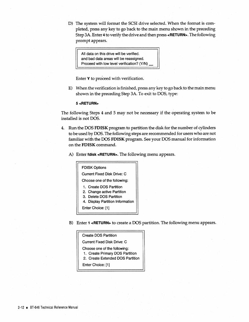
D) The system will format the SCSI drive selected. When the format is completed, press any key to go back to the main menu shown in the preceding Step 3A. Enter 4 to verify the drive and then press <RETURN>. The following prompt appears.
All data on this drive will be verified. and bad data areas will be reassigned. Proceed with low level verification? (Y/N)_
Enter Y to proceed with verification.
E) When the verification is finished, press any key to go back to the main menu shown in the preceding Step 3A. To exit to DOS, type:
5 <RETURN>
The following Steps 4 and 5 may not be necessary if the operating system to be installed is not DOS.
4. Run the DOS FDISK program to partition the disk for the number of cylinders to be used by DOS. The following steps are recommended for users who are not familiar with the DOS FDISK program. See your DOS manual for information on the FDISK command.
A) Enter fdisk <RETURN>. The following menu appears.
FDISK Options
Current Fixed Disk Drive: C
Choose one of the following:
1. Create DOS Partition 2. Change active Partition 3. Delete DOS Partition 4. Display Partition Information
Enter Choice: [1]
B) Enter 1 <RETURN> to create a DOS partition. The following menu appears.
2-12 • 8T-646 Technical Reference Manual
Create DOS Partition
Current Fixed Disk Drive: C
Choose one of the following: 1. Create Primary DOS Partition 2. Create Extended DOS Partition
Enter Choice: [1]

C) Enter 1 <RETURN> to create a primary 005 partition. The next menu appears.
Create Primary DOS Partition
Current Fixed Disk Drive: C
Choose one of the following:
Do you wish to use the maximum size for a DOS partition and make the DOS partition active (yIN) ..................... ? M
D) Enter Y <RETURN> to create a primary DOS drive partition with the maximum size. The following prompt appears.
System will now restart
Insert DOS diskette in drive A: Press any key when ready ...
When the partitioning has been completed (indicated by another prompt), press any key to return to 005.
5. Install 005 by running the FORMAT program as instructed by 005 normal installation procedures. The next steps are recommended for operators who are not familiar with the 005 FORMAT program.
A) Run the FORMAT program by typing:
format c:/s/v <RETURN>
B) The system displays the following format warning:
WARNING: ALL DATA ON NON-REMOVABLE DISK DRIVE C: WILL BE LOST!
Proceed with Format (YIN)?
C) TypeY <RETURN>.
D) When the format has been completed, the following prompt appears.
Format complete System transferred Volume label ( 11 characters, ENTER for name )?
E) Enter any legal file name to label the volume just created. Refer to your system operator's manual for more details on the 005 format procedures.
This concludes the BT-646 hardware and software installation procedures.
Unpacking and Installation I 2-13

WARRANTY INFORMATION
If damage to the board has occurred, return it in the protective envelope with this manual to your BusLogic board supplier. The shipping agent should also be notified if the unit has been damaged during shipment. The BusLogic warranty conditions are given in the back of this manual.
2-14 • BT-646 Technical Reference Manual
11'---_____ _ ELECTRICAL INTERFACE
This section provides the user with a complete description of the name, function, and applicable logic level of all signals between the BT-646 and the host system. It also describes the signals processed by the SCSI protocol chip and the floppy controller chip. This section is divided into two parts:
• Micro Channel System Bus Electrical Interface and
• SCSI Bus Electrical Interface.
MICRO CHANNEL SYSTEM Bus ELECTRICAL INTERFACE
The BT-646 is electrically and mechanically compatible with the Input/Output (I/O) bus used in Micro Channel computers. Physically, this I/O bus is contained on the card edge connector. The bus master control logic on the BT -646 controls the Micro Channel system bus arbitration and data transfer operations. During bus master data transfers, the BT-646 takes control of the system bus and transfers data directly to and from the main system memory. Both odd and even starting addresses are supported by the BT-646.
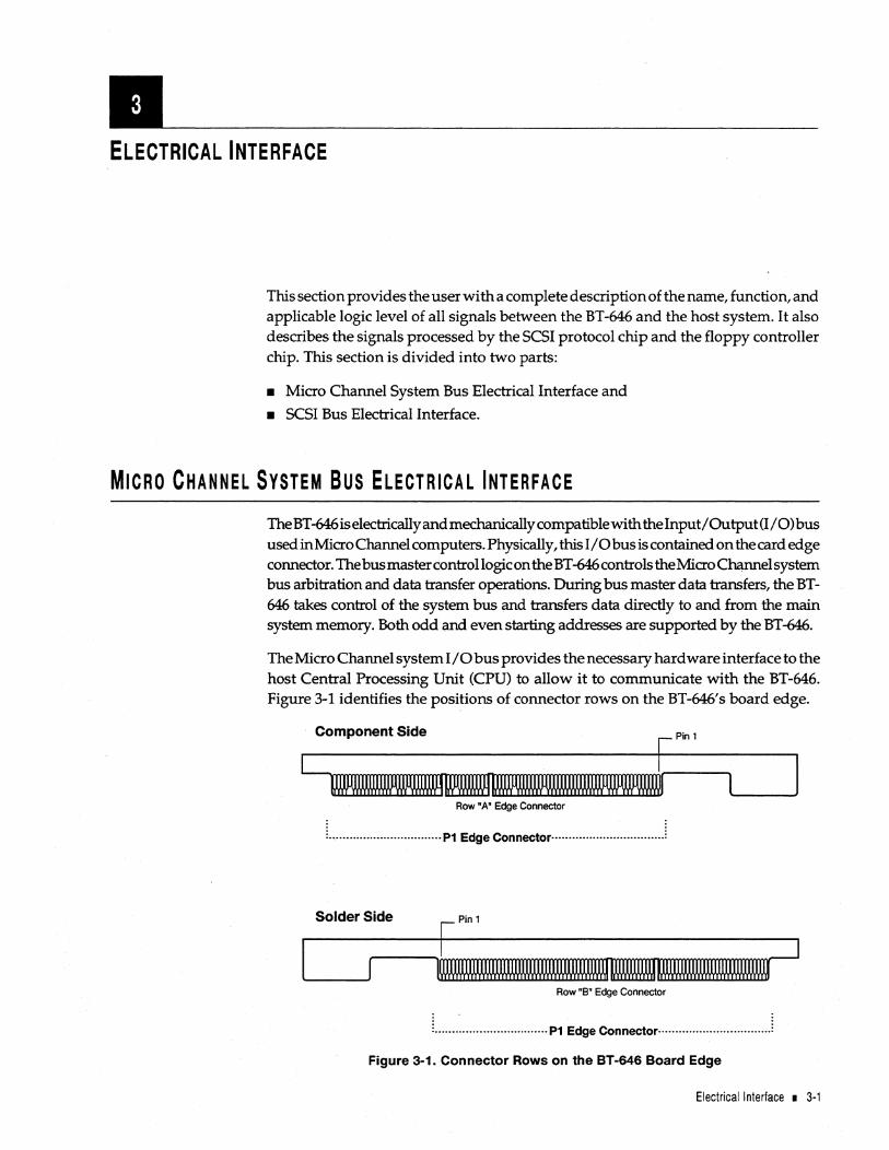
The Micro Channel system I/O bus provides the necessary hardware interface to the host Central Processing Unit (CPU) to allow it to communicate with the BT-646. Figure 3-1 identifies the positions of connector rows on the BT -646' s board edge.
Component Side Pin 1
um.M~ Row 'A' Edge Connector
· . · . · . : .................................. P1 Edge Connector·································:
Solder Side Pin 1
~~ Row'S" Edge Connector
. . . . L ................................ P1 Edge COnnector ................................. ~
Figure 3-1. Connector Rows on the BT-646 Board Edge
Electrical Interface I 3-1
Summary of Micro Channel Signals
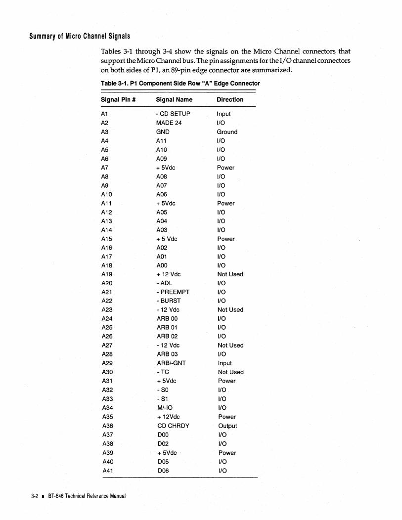
Tables 3-1 through 3-4 show the signals on the Micro Channel connectors that support the Micro Channel bus. The pin assignments for the 1/ 0 channel connectors on both sides of PI, an 89-pin edge connector are summarized.
Table 3-1. P1 Component Side Row "A" Edge Connector
Signal Pint Signal Name Direction
A1 -CD SETUP Input
A2 MADE 24 I/O
A3 GND Ground
A4 A11 I/O
A5 A10 I/O
A6 A09 I/O
A7 +5Vdc Power
A8 A08 I/O
A9 A07 I/O
A10 A06 I/O
A11 + 5Vdc Power
A12 A05 I/O A13 A04 I/O
A14 A03 I/O
A15 + 5 Vdc Power A16 A02 I/O
A17 A01 I/O A18 AOO I/O A19 + 12 Vdc Not Used
A20 -ADL I/O
A21 - PREEMPT I/O A22 -BURST I/O
A23 -12 Vdc Not Used
A24 ARB 00 I/O A25 ARB 01 I/O A26 ARB 02 I/O
A27 -12 Vdc Not Used
A28 ARB 03 I/O
A29 ARB/-GNT Input
A30 -TC Not Used
A31 +5Vdc Power
A32 -SO I/O.
A33 - S1 I/O A34 M/-IO I/O
A35 + 12Vdc Power
A36 CDCHRDY Output
A37 000 I/O
A3S 002 I/O
A39 +5Vdc Power
A40 005 I/O
A41 006 I/O
3-2 • BT-646 Technical Reference Manual

Table 3-1. P1 Component Side Row "A" Edge Connector (Continued)
Signal Pin # Signal Name Direction
A42 D07 I/O A43 GND Ground
A44 - DS 16 RTN Input
A45 - REFRESH Not Used
A46 Access Key Access Key
A47 Access Key Access Key
A48 + 5 Vdc Power
A49 D10 I/O A50 D11 1/0 A51 D13 1/0 A52 + 12 Vdc Power
A53 RESERVED Not Used
A54 -SBHE 1/0 A55 - CD DS 16 Not Used
A56 + 5 Vdc Power
A57 -IRQ 14 Output
A58 -IRQ 15 Output
A59 RESERVED Not Used A60 RESERVED Not Used
A61 GND Ground A62 RESERVED Not Used
A63 RESERVED Not Used
A64 RESERVED Not Used
A65 + 12 Vdc Not Used
A66 D19 1/0 A67 D20 1/0 A68 D21 I/O A69 +5Vdc Power
A70 D24 1/0 A71 D25 I/O A72 D26 1/0 A73 + 5 Vdc Power
A74 D30 1/0 A75 D31 1/0 A76 RESERVED Not Used
A77 + 12 Vdc Power
A78 - BE3 Output
A79 - DS 32 RTN Input
A80 -CD OS 32 Not Used
A81 + 5 Vdc Power
A82 A26 1/0 A83 A27 1/0 A84 A28 1/0
A85 +5 Vdc Power
A86 RESERVED Not Used
A87 RESERVED Not Used
A88 RESERVED Not Used
A89 GND Ground
Electrical Interface • 3-3

Table 3-2.· P1 Solder Side Row "8" Edge Connector
Signal Pint Signal Name Direction
B1 AUDIO GND Not Used
B2 AUDIO Not Used
B3 . GND Ground
B4 14.3 MHz OSC Not Used
B5 GND Ground
B6 A23 1/0
B7 A22 1/0
B8 A21 1/0
B9 GND Ground
B10 A20 1/0
B11 A19 1/0
B12 A18 1/0
B13 GND Ground
B14 A17 1/0
B15 A16 1/0
B16 A15 110 817 GND Ground
B18 A14 1/0
B19 A13 1/0
B20 A12 110 B21 GND Ground
B22 -IRQ 09 Output
B23 -IRQ 03 Not Used
B24 -IRQ 04 Not Used
B25 GND Ground
B26 -IRQ 05 Not Used
B27 -IRQ 06 Not Used
B28 -IRQ 07 Not Used
B29 GND Ground
B30 RESERVED Not Used
B31 RESERVED Not Used
B32 -CHCK Input
B33 GND Ground
B34 -CMD 1/0
B35 CHRDYRTN Input
B36 -CD SFDBK Output
B37 GND Ground
B38 D01 1/0
B39 ·003 1/0
840 004 110 B41 GND Ground
B42 CHRESET Input
B43 RESERVED Not Used
B44 RESERVED Not Used
B45 GND Ground
3-4 • BT-646 Technical Reference Manual

Table 3-2. P1 Solder Side Row "8" Edge Connector (Continued)
Signal Pin# Signal Name Direction
B46 Access Key Access Key
B47 Access Key Access Key
B48 D08 I/O
B49 D09 1/0
B50 GND Ground
B51 D12 1/0
B52 D14 1/0
B53 D15 1/0
B54 GND Ground
B55 -IRQ 10 Output
B56 -IRQ 11 Output
B57 -IRQ 12 Output
B58 GND Ground
B59 RESERVED Not Used
B60 RESERVED Not Used
B61 RESERVED Not Used
B62 RESERVED Not Used
B63 GND Ground
B64 D16 1/0
B65 D17 1/0
B66 D18 1/0
B67 GND Ground
B68 D22 1/0
B69 D23 1/0
B70 RESERVED Not Used
B71 GND Ground
B72 D27 1/0
B73 D28 1/0
B74 D29 1/0
B75 GND Ground
B76 - BEO Output
B77 - BE1 Output
B78 - BE2 Output
B79 GND Ground
B80 TR32 Output
B81 A24 1/0
B82 B25 1/0
B83 GND Ground
B84 A29 1/0
B85 A30 I/O
B86 A31 I/O
B87 GND Ground
B88 RESERVED Not Used
B89 RESERVED Not Used
Electrical Interface • 3-5

P1 Input/Output Signal Descriptions
This section describes signals from each connector of the Micro Channel bus signals. I/O adapters should be designed with a maximum of two low-power Shottky (LS) loads per lirie. Signals preceded by a hyphen (-) indicate an active low signal.
Table 3-3. P1 Signal Descriptions
SIGNAL DEFINITION
AD-A23 Address Bits 0-23: These signals are used to address memory and 110 slaves attached to the channel. AD is the least significant bit (LSB) and A23 is the most significant bit (MSB). These 24 address lines allow access of up to 16 MBytes of memory. Only the lower 16 address lines (AD-A15) are for 1/ o operations, and all 16 lines must be decoded by the 110 slave. AD-A23 are generated by the controlling master. Valid addresses generated by the controlling master are unlatched on the channel and, if required must be latched by the slaves using either the leading or trailing edge of the Address Decode Latch signal or the leading edge of the Command signal. AD-A23 must be driven with tristate drivers.
A24-A31 Address Bits 24-31: These signals are used with AO-A23 to address memory attached to the channel. AO is the LSB and A31 is the MSB. These 32 address lines allow access of up to 4 GBytes of memory. Only the lower 16 address lines (AD -A15) are used for I/O operations. A24-A31 are generated by the controlling master. Valid addresses generated by the controlling master are unlatched on the channel and, if required, must be latched by the slaves using either the leading or trailing edge of the Address Decode Latch signal or the leading edge of the Command signal. The Address Bits 0-31 signals must be driven with tristate .drivers.
-ADL Address Decode Latch: This signal, driven by the controlling master, is provided as a convenient way for the slave to latch valid addresses and status bits. This signal can be used by slaves to latch the address from the bus. This signal is not active during Matched-Memory cycles. This signal is driven with a tristate driver.
ARBa-ARB3 Arbitration Bus Priority Levels: These signals comprise the Arbitration
ARB/-GNT
3-6 • BT-646 Technical Reference Manual
. bus and are used to present priority levels for participants seeking control of the bus. The Arbitration Bus Priority Level 0-3 signals, the least significant through most significant bits respectively, support up to 16 priority levels.
The highest hexadecimal value of the Arbitration bus (Hex F) has the lowest priority, and the lowest value (Hex 0) has the highest priority. A participant is allowed to change the state of the Arbitration bus only immediately after the rising edge of the Arbitrate/-Grant signal. All participants monitor the Arbitration bus and the lower priority participants withdraw their priority levels by not activating less-significant arbitration bits.
The hexadecimal code of the highest priority requester is valid on the Arbitration bus after a settling time. After the channel is granted to a requester, the highest priority participant continues to drive its priority lines. These bidirectional lines are active high and must be driven with open-collector drivers.
Arbitrate/-Grant: When the signal is high, it indicates an Arbitration cycle is in process. When it is low, it is the acknowledgment from the central arbitration control point to an Arbitrating bus participant (local arbiter) and the DMA controller that channel control has been granted. This signal is driven high by the central arbitration control point within a specified time after the Status Bits 0 and 1 signals, the Burst and the Command signal become inactive. The negative-tO'-positive transition of this signal initiates an Arbitration cycle; the positive-to-negative transition terminates the Arbitration cycle. Only the central arbitration control point activates and deactivates this signal. The signal must be used by all local arbiters to gate their address data and transfer control bus drivers off during Arbitration cycles. This signal is driven with a bus driver.

Table 3-3. P1 Signal Descriptions (Continued)
SIGNAL DEFINITION
-BEO - -BE3 Byte Enable 0-3: These signals are used during data transfers with 32-bit slaves to indicate which data bytes will be placed on the bus. Data transfer of 8,16,24, or 32 contiguous bits are controlled by these signals during transfers involving 32-bit slaves only. These signals are driven by the controlling master when the Translate 32 signal is inactive, and by the Central Translator Logic (for those operations involving a 16-bit master with a 32-bit slave) when the Translate 32 signal is active. These signals are unlatched on the bus and, if required, must be latched by 32-bit slaves. These signals are driven with tristate drivers.
-BURST: Burst: This signal indicates to the central arbitration control point the extended use of the channel for transferring a block of data. This type of data transfer is called a Burst cycle. This signal is shared by all local arbiters. This signal is driven active by the local arbiter after being granted the channel. The local arbiter must deactivate this signal during the last transfer cycle. This signal must be driven with an open-collector driver.
-CD SFDBK (n) Card Selected Feedback: When the controlling master addresses a memory slave or an 1/0 slave, the addressed slave drives this signal active as a positive acknowledgment of its presence at the address specified. The (n) indicates this signal is unique to each channel connector (one independent signal line per connector). This signal is unlatched by any slave with a valid select decode and is driven by any slave selected by any select mechanism except the Card Setup signal. The slave does not drive this signal during the Configuration cycle. This signal is driven with a totem-pole driver.
-CD SETUP (n) Card Setup: This signal is driven by system logic to select individual channel connectors during system configuration and error-recovery procedures. The (n) indicates this signal is unique to each channel connector (one independent signal line per connector). When this signal is activated, a specific channel connector is selected and access to the adapter's configuration data space is obtained. The 10 and configuration data can be obtained by an 1/0 Read operation; the configuration data is stored by an 1/0 Write operation. Each channel connector has a unique card setup signal. This signal is driven with a totem-pole driver.
CD CHRDY (n) Channel Ready: This signal, normally active (ready), is pulled inactive (not ready) by a memory or 1/0 slave to allow additional time to complete a channel operation. The (n) indicates this Signal is unique to each channel connector (one independent signal line per connector). During a Read operation, a slave ensures that data will be valid on the data bus within the time specified after releasing the signal toa Ready state. The slave also holds the data long enough for the controlling master to sample. A slave may also use this signal during a Write operation if more time is needed to store the data from the bus. This signal is derived with a valid address decode ANDed with status. This signal is driven with a totem-pole driver.
-CD OS 32-,n) Card Data Size 32: This signal is driven by 32-bit slaves to provide an indication on the bus of a 32-bit data port at the location addressed. The (n) indicates this signal is unique to a channel connector position (one independent signal per connector). This signal is unlatched and derived from a valid address decode. All 32-bit slaves must drive this signal. This signal is inactive for an 8- or 16-bit data port. It must be driven with a totem-pole driver.
-CHCK Channel Check: This signal is used to indicate a serious error (such as a parity error) that threatens the continued operation of the system. This signal is driven active to indicate the error condition and must remain active until the Channel Check signal's interrupt handler resets it. This signal is driven with an open-collector driver to allow sharing.
Electrical Interface I 3-7

Table 3-3. P1 Signal Descriptions (Continued)
SIGNAL
CHRDYRTN
CHRESET
-CMD
-OS 32 RTN
00-015
016-031
-OS 16 RTN
3-8 • 8T-646 Technical Reference Manual
DEFINITION
Channel Ready Return: This output signal is a positive AND of the Channel Ready signals. If all devices drive the Channel Ready signal active, this output is active. It is provided to allow the controlling master to monitor the ready information. This signal must be driven with a bus driver.
Channel Reset: This signal is generated by the system logic to reset or to initialize all adapters at power on or during a low line voltage condition. During a power-on sequence, this signal is active for aspecified minimum time. The system can aJso activate this signal under program control. This signal is driven with a bus driver.
Command: This signal is used to defirie when data is valid on the data bus. The trailing edge of this signal indicates the end of the bus cycle. This signal indicates to the slave how long data is valid on the bus. During Write operations, the data is valid on the bus as long as this signal is active. During Read operations, the data is valid on the bus between the leading and trailing edges of this signal and must be held on the bus until after it goes inactive. This signal can be used by the slaves to latch the address on the bus. Latched status lines gated by this signal provide the timing control of valid data. Slaves should use transparent latches to latch address and status information with the leading edge of this signal. This signal is not active during Matched-Memory cycles. It must be driven with a tristate driver ..
Data Size 32 Return: This output signal is a negative OR of the Card Data Size 32 signal from each channel connector. If any device drives its Card Data Size 32 signal active, then this output is active. This signal is provided to allow controlling masters to monitor data size information. This signal must be driven with a bus driver.
Data Bits 0-15: These signals provide data bus Bits 0-7 (low byte) and 8-15 (high byte) for the controlling master and slaves. DO is the LSB and 015 the MSB. All 8-bit slaves on the channel must use 00-07 to communicate with the controlling master. During Read cycles, data is valid on these signals after the leading edge but before the trailing edge of the Command signal, and must remain valid until after the trailing edge of the Command signal. However, during Write cycles, data is valid as long as the Command signal is active. These signals must be driven with tristate drivers.
Data Bits 16-31: These signals are used with the Data Bits 0-15 signals to provide data bus bits to the controlling master and slaves. DO is the LSB and 031 the MSB. All 32-bit transfers from the controlling master to 8-bit slaves are converted to four 8-bit transfers, and all are transmitted on the Data Bits 0-7 Signals. All 32-bit transfers from the controlling master to 16-bit slaves are converted to two 16-bit transfers, and all are transmitted on the Data Bits 0-15 signals. During Read cycles, data is valid on these signals after the leading edge of the Command signal but before the trailing edge of the Command signal. However, during Write cycles, data is valid as long as the Command signal is active. These signals must be driven with~ate drivers.
Data Size 16 Return: This output signal is a negative OR of the Card Data Size 16 signal from each channel connector. If any device drives its Card Data Size 16 signal active, this output is active. This signal is provided to allow the controlling master to monitor the data size information. This signal must be driven with a bus driver.

Table 3-3. P1 Signal Descriptions (Continued)
SIGNAL
-IRQ 9-12, & -IRQ 14-15
MADE 24
M/-IO
-PREEMPT
-SO,-S1
DEFINITION
Interrupt Request: These signals are used to signal that a device requires attention. The interrupt priority sequence is Interrupt Request 9-12, 14, 15, 3-7. An interrupt request is generated when a slave drives one of the interrupt request signals low. The polarity of the interrupt request signals makes it possible for multiple slave to share the same interrupt level. This is called interrupt sharing. These Signals must be driven with an open-collector driver.
Memory Address Enable 24: This signal indicates when an extended address is used on the bus. If a Memory cycle is in progress and this signal is inactive, an extended address greater than 16 MBytes is being presented; if this signal is active, an unextended address less than or equal to 16 MBytes is being presented. This signal is driven by the controlling master and is decoded by all memory slaves, regardless of their address space size. It is driven with a tristate driver.
Memory/-Input Output: This signal distinguishes a Memory cycle from an I/O cycle. When this signal is high, a Memory cycle is in progress. When M/-IO is low, an I/O cycle is in progress. This signal is driven with a tristate driver.
Preempt: This signal is used by arbitrating bus participants (local arbiters) to request use of the channel through arbitration. Any local arbiter with a channel request activates this signal and causes an Arbitration cycle to occur. A local arbiter removes its preempt signal upon being granted the channel. This bidirectional signal must be driven with an open-collector driver.
Status Bits 0 and 1: These signals indicate the start of a Channel cycle and also define the type of Channel cycle. When used with the Memory/Input Output signal, memory ReadIWrite operations are distinguished from I/O ReadIWrite operations. These signals are latched by the slave, as required, using the leading edge of the Command signal or the trailing edge of the Address Decode Latch signal. These signals are driven with a tristate driver.
Data is moved to or from the bus based on the Command signal and a latched decode of the address, the status lines (the Status Bit 0 signal exclusive or the Status Bit 1 signal), and the Memory/-Input Output signal.
Slaves must support a full decode of the Status Bit 0 signal and the Status Bit 1 signal. The following table shows the proper states of the Memory/Input Output signal, the Status Bit 0 signal, and the Status Bit 1 signal in decoding I/O and memory ReadIWrite commands.
I/O and Memory Transfer Controls
M/-IO SO -S1 Function
0 0 0 Reserved 0 0 I/O Write Command 0 1 0 I/O Read Command 0 1 1 Reserved
0 0 Reserved 0 Memory Write Command
0 Memory Read Command Reserved
Electrical Interface I 3-9

Table 3-3. P1 Signal Descriptions (Continued)
SIGNAL
-SBHE
-TC
Tr32
3-10 • 8T-646 Technical Reference Manual
DEFINITION
An I/O Write command instructs an 1/0 slave to store the data on the data bus. The data must be valid on the bus from the leading edge of the Command signal and must be held on the bus until after the Command signal goes inactive. Addresses on the bus must be valid before the Status Bit 0 signal goes active.
An 1/0 Read command instructs an 1/0 slave to drive its data on to the data bus. The data must be placed on the bus following the leading edge of the Command signal, must be valid before the trailing edge of the Command signal, and must be held on the bus until the Command signal goes inactive. Addresses on the bus must be valid before the Status Bit 1 signal goes active. .
A memory Write command instructs the memory to read the data on the data bus. The data must be valid on the bus from the leading edge of the Command signal and must be held on the bus until after the Command signal goes inactive.
Addresses on the bus must be valid before the Status Bit 0 signal goes active.
A memory Read command instructs the memory to drive its data onto the data bus. The data must be placed on the bus following the leading edge of the Command signal. The data must be valid before the trailing edge of the Command signal, and must be held on the bus until the Command signal goes inactive. Addresses on the bus must be valid before the Status Bit 1 signal goes active.
System Byte High Enable: This signal indicates and enables transfer of data on the high byte of the data bus (08-015), and is used with the Address Bit 0 signal to distinguish between high-byte transfers (08- 015) and low-byte transfers (00- 07). All 16-bit slaves decode this line, but 8-bit slaves do not. This signal is driven with a tristate driver.
Terminal Count: This signal provides a pulse during a Read or Write command to indicate that the terminal count of the current OMA channel has been reached. This indicates to the OMA slave the last cycle to be performed of a preprogrammed OMA block transfer. This signal is available on the channel only during OMA operations. It is driven with a tristate driver by the OMA controller.
Translate 32: This signal is driven inactive by 32-bit controlling masters and received by the Central Translator Logic. This signal can also be received by any 32-bit slave. When this signal is inactive, a 32-bit controlling master drives the Byte Enable 0-3 signals. When this signal is active, the Central Translator Logic drives the Byte Enable 0-3 signals. It must be driven by a tristate driver.

SCSI Bus ELECTRICAL INTERFACE
SCSI Electrical/Physical
The BT-646 interfaces the Micro Channel bus to a SCSI general purpose 8-bit bidirectional bus. The SCSI port is controlled by a SCSI interface chip which supports arbitration, selection, and reselection with a minimum need for processor attention. The SCSI interface controller supports target mode and synchronous SCSI transfers. The BT -646S includes single-ended drivers and receivers (built into the SCSI interface chip) which allow a maximum cable length of six meters. The BT-646D includes differential drivers and receivers which allow a maximum cable length of 25 meters.
A minimum conductor size of 28 A WG should be employed to minimize noise effects and ensure proper distribution of terminator power.
J1 is a 50-pin, non-shielded SCSI device connector consisting of two rows of 25 male pins with adjacent pins 2.54 mm (0.1 in) apart. J2 is a 50-contact, shielded SCSI device connector.
For the BT-646S to support a 10 MBytes/sec synchronous and a 7 MBytes/sec asynchronous SCSI data rate in single-ended mode, proper termination and cabling are important. The BT -646S uses regulated termination with 100 ohm resistors. It is recommended that regulated termination be used at both ends of the SCSI cable.
For the BT-646D, all signals are terminated with 330 ohms from the differ-ential nodes to +5 volts and ground, respectively, and with 150 ohms between each differential pair.
Single-Ended Output Characteristics. Each signal driven has the following output characteristics when measured at the connector:
Signal assertion = 0.0 volts de to 0.4 volts
Minimum driver output capability = 48 milliamps (sinking) at 0.5 volts de (7438 or equivalent)
Signal negation = 2.0 volts de to 5.25 volts de.
Devices receiving the BT-646S's output should be of the SCHMITT trigger type to improve noise immunity, 741514, 74LS240, or the equivalent. The device should not load the bus with more than two standard low-power Shottky (LS) input loads per line, and should terminate the controller output signals with 100 ohm terminators if the BT -646S is used.
Single-Ended Input Otaracteristics. Each signal received by the controller should have the following input characteristics when measured at the SCSI device's connector:
Signal true = 0.0 volts de to 0.8 volts de
Maximum total input load = -0.4 milliamps at 0.4 volts de
Signal false = 2.0 volts de to 5.25 volts de
Minimum input hysteresis = 0.2 volts de.
Electrical Interface • 3-11

Differential Output Characteristics. Each signal driven should have the following output characteristics when measured at the connector:
Signal true = when +SIGNAL is more positive than -SIGNAL
Minimum low-level output current = 55 milliamps at 1.7 volts dc maximum
Minimum high-level output current = -55 milliamps at 2.7 volts dc minimum
Differential Input Characteristics. Each signal received by the controller should have the following input characteristics when measured at the SCSI device's connector:
Signal true = when +SIGNAL is more positive than -SIGNAL
Maximum input load = ±2.0 milliamps
Maximum input capacitance = 25 pF·
Minimum input hysteresis = 35 millivolts.
Terminator Power (Pin 26). Usually only SCSI initiators should provide termination power.
VTerm. = 4.25 volts dc to 5.25 volts dc
1.0 amp minimum source drive capability
1.0 milliamp maximum sink capability.
Refer to Figure 3-2 for a schematic representation of how terminator power is provided on the BT-646.
vee
Resistor
Fuse
Term Power Detect Input
To Terminating Resistors
To Term Pwr (SCSI Bus Pin 26)
Figure 3-2. Terminator Power Schematic
Terminators. SCSI devices are daisy chained together using a common cable. All signals are common between all SCSI devices, and both ends of the cable are terminated with small hardware components called terminators. Terminators, which are connected to SCSI devices or SCSI cables, make data transfer on a SCSI network more reliable.
Devices connected to SCSI chains must have the correct number of terminators for proper operation and to prevent damage to the SCSI chip on the BT -646. There can be no more than two terminators in a chain of SCSI devices-each at one physical end of the chain. Therefore, if more than two SCSI devices are connected in a SCSI daisy chain, the middle devices in the control cable must have their terminator resistor packs removed. See Section 2, the "Unpacking and.Installation" section, of this manual for additional details on installation.
3-12 • BT-646 Technical Reference Manual

SCSI Signal Interface
The BT -646 single-ended SCSI interface signals for J1 and J2 are shown in Table 3-4_ Table 3-5 lists the BT -646 differential SCSI interface signals for J1 and J2- A plus sign
(+) denotes an active high signal. A hyphen (-) denotes an active low signal.
The pin descriptions for J4, a 4-pin disk drive power connector are shown in Table 3-6_
Table 3-4_ J1 & J2 Single-Ended SCSI Interface Signal Pin Assignments
Signal Pin Signal Name Signal Pin Signal Name Direction (Initiator)
1 Ground 2 -OBO I/O
3 Ground 4 -OB1 1/0
5 Ground 6 -OB2 1/0
7 Ground 8 -OB3 1/0
9 Ground 10 -OB4 1/0
11 Ground 12 -OB5 1/0
13 Ground 14 -OB6 1/0
15 Ground 16 -OB7 1/0
17 Ground 18 -OBP
19 Ground 20 Ground
21 Ground 22 Ground
23 Reserved 24 Reserved
25 Open 26 TERMPWR
27 Reserved 28 Reserved
29 Ground 30 Ground
31 Ground 32 -ATN Output
33 Ground 34 Ground
35 Ground 36 -BSY
37 Ground 38 -ACK Output
39 Ground 40 -RST Output
41 Ground 42 -MSG Input
43 Ground 44 -SEL Input
45 Ground 46 -CIO Input
47 Ground 48 -REO Input
49 Ground 50 -1/0 Input
Electrical Interface I 3-13
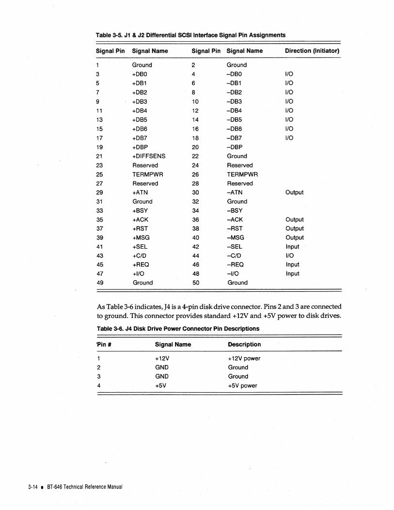
Table 3-5. J1 & J2 Differential SCSI Interface Signal Pin Assignments
Signal Pin Signal Name Signal Pin Signal Name Direction (Initiator)
Ground 2 Ground
3 +OBO 4 -OBO 1/0
5 +OB1 6 -OB1 I/O
7 +OB2 8 -OB2 I/O
9 +OB3 10 -OB3 I/O
11 +OB4 12 -OB4 I/O
13 +OB5 14 -OB5 1/0
15 +OB6 16 -OB6 1/0
17 +OB7 18 -OB7 1/0
19 +OBP 20 -OBP
21 +OIFFSENS 22 Ground
23 Reserved 24 Reserved
25 TERMPWR 26 TERMPWR
27 Reserved 28 Reserved
29 +ATN 30 .... ATN Output
31 Ground 32 Ground
33 +BSY 34 -BSY
35 +ACK 36 -ACK Output
37 +RST 38 -RST Output
39 +MSG 40 -MSG Output
41 +SEL 42 -5EL Input
43 +C/O 44 -C/O I/O
45 +REO 46 -REO Input
47 +1/0 48 -I/O Input
49 Ground 50 Ground
As Table 3-6 indicates, J4 is a 4-pin disk drive connector. Pins 2 and 3 are connected to ground. This connector provides standard + 12V and +5V power to disk drives.
Table 3-6. J4 Disk Drive Power Connector Pin Descriptions
·Pin# Signal Name Description
1 +12V +12V power
2 GNO Ground
3 GNO Ground
4 +5V +5V power
3-14 • 8T-646 Technical Reference Manual

SCSI Signal Definitions
The definitions for SCSI interface signals are shown in Table 3-7.
Table 3-7. J1 & J2 SCSI Interface Signal Descriptions
Differential Signal
-RST +RST
-SEL +SEL
-BSY +BSY
-C/D +C/D
-I/O +1/0
-REQ +REQ
-ACK +ACK
-ATN +ATN
-MSG +MSG
Single-Ended Definition Signal
-RST Reset: This "OR Tied" signal, which is asserted by the initiator, causes the SCSI bus to cease all operations and return to the Idle condition. This signal is normally used during a power-up sequence. A reset during a Write operation would cause incorrect data to be written on the disk.
-SEL Select When this signal is asserted by the initiator, along with an initiator 10 and target 10 data bit (0 -7), it
causes the addressed target to be selected. This signal must be deasserted by the initiator after the target asserts the Busy (-BSY) signal in response to a proper selection.
-BSY Busy: When this "OR Tied' signal is asserted, it indicates that the bus is being used.
-c/O Control/Data: When this signal is asserted by the target, it indicates that control information is to be transferred on the data bus. Oeassertion of this signal indicates that data information is to be transferred on the data bus.
-I/O Input/Output When this signal is asserted by the target, it indicates that information will be transferred to the
initiator from the target. Oeassertion indicates that information will be transferred to the target from the initiator. This signal is also used to distinguish between the Selection and Reselection phases.
-REQ Request: When this signal is asserted by the target, it indicates that an 8-bit byte is to be transferred on the data bus. The Request (REO) signal is deasserted following the assertion of the Acknowledge (ACK) signal from the host. The Request (REO) and Acknowledge (ACK) signals control the handshaking.
-ACK Acknowledge: When this signal is asserted by the initiator, it indicates data has been accepted by the initiator or that data is ready to be transferred from the initiator to the target.
-ATN Attention: This signal is driven by the initiator to indicate the Attention condition.
-MSG Message: When this signal is asserted by the target, it indicates the Message phase. The state of the Input! Output (-I/O) signal when it is asserted indicates MESSAGE IN or MESSAGE OUT.
-DBO-7 & -DBP -DBO-7 +DBO-7 & +DBP & -DBP
Data Bits & Parity: These eight bidirectional data lines and one odd parity signal are used to transfer 8-bit parallel data over the SCSI bus. Bit 7 is the MSB and has highest priority during the Arbitration phase. Parity is not valid during the Arbitration phase. The use of the parity bit is an option. See Section 2 of this manual for the switch settings to enabl~ or disable SCSI parity.
Electrical Interface • 3-15

3-16 • 8T-646 Technical Reference Manual

IIL---.-____ _ HARDWARE DESCRIPTION
This section describes the functional hardware operation of the BT -646. This description encompasses the hardware control registers that are mapped into the Micro Channel system's I/O address space. The issuance of commands, the coordination of data flow, and the basic management of the BT-646's hardware components are discussed. A complete understanding of the hardware control registers and their operation will enable the system software programmer to (1) fully understand the software interface description in Section 5, the "Software Interface" section of this manual, and (2) develop a fully functional software driver for single or multitasking operating systems.
HOST DMADATA TRANSFER CONTROL
All host data transfers are performed by the BT -646 as a Micro Channel 16-bit or 32-bit bus master. This is the most efficient method to transfer data between the SCSI devices and the system memory. The BT -646 senses the speed of the Micro Channel system and adjusts its data transfer rate accordingly.
HARDWARE CONTROL REGISTERS
The BT -646' s I/O interface consists of three hardware control registers that are used by the host to issue start commands to the BT-646, to gain status information about the BT-646's operation, and to manage interrupts generated by the BT-646. These registers are located in the Micro Channel I/O address space at three consecutive addresses. The beginning or base address is determined by the I/O base address switch settings described in Section 2. Table 4-1 provides a summary of these registers. Each of these registers is 8-bits wide and performs the functions described as follows.
Table 4-1. BT-646's Hardware Control Registers
ADDRESS TYPE
1/0 Base Address + 0 W 1/0 Base Address + 0 R
1/0 Base Address + 1 W I/O Base Address + 1 R
1/0 Base Address + 2 R
DESCRIPTION
Control Register Status Register
CommandlParameter Register Data In Register
Interrupt Registef
Hardware Description • 4-1

Control Register (Write Only) 110 Base Address + 0
761543210
Hard Reset (RHARD) I. I I Soft Reset (RSOFT)
Interrupt Reset (RINT)
SCSI Bus Reset (RSBUS) --------'
Figure 4-1. Control Register (Write)
Reserved (Set to Zero)
The host system' s CPU uses this register to specify programmable options within the BT-646 (e.g., soft reset, hard reset, SCSI bus reset). For example, the host system's CPU can stop all BT -646 activity immediately by setting this register's Bit 6, the Soft Reset bit (RSOFT). This is a write-only register.
Bits D-3-These bits are reserved and must be set to zero.
Bit 4 Reset SCSI Bus (RSBUS)-When this bit is set to a one, the Reset signal on the SCSI bus is maintained true for at least 25 microseconds. This Reset condition immediately clears all SCSI devices from the bus. The assertion of the SCSI Reset condition supersedes all other activity on the SCSI bus. See the heading "Reset Operations" later in this section for additional details on the Reset operation.
Bit 5 Reset Interrupt (RINT)-The Micro Channel system's CPU sets this bit to acknowledge a BT-646 interrupt. When this bit is set to one by the Micro Channel CPU, the BT -646' s hardware-generated interrupt is reset and the Interrupt Register is cleared. Note that all bits in the Interrupt Register are cleared by the setting this bit.
Bit 6 Soft Reset (RSOFr)-When this bit is set to one, it causes all BT -646 activity to stop immediately. All mailboxes, command control blocks, and any pending commands are discarded by the BT -646. Previous mailbox pointers must be cleared by host processes. The primary difference between a hard and soft reset is that this bit does not effect a SCSI Bus Reset condition. Once the soft reset activity has been completed by the BT-646, the BT-646 must be reinitialized for any future operation. This state is indicated by the setting of the Host Adapter Ready bit (HARDY) and the Initialization Required bit (INREQ) in the Status Register.
Bit 7 Hard Reset (RHARD)-The setting of this bit causes the BT-646 to enter an initial condition power-on state. Any command in process is stopped and pending commands are abandoned. The BT -646 will execute its. internal diagnostic function and report any errors. During reset, the Diagnostic Active bit (DACT) is set. Once the hard reset activity has been completed by the BT -646, the BT -646 must be reinitialized for any future operation. This state is indicated by the setting of the Host Adapter Ready bit (HARDY) and the Initialization Required bit (INREQ) in the Status Register.
Specific operation bits in the Control Register are automatically reset by the BT-646 when the specific operation is completed. The host-controlling software is not required to reset the operational control bit for a specific function.
4-2 • BT-646 Technical Reference Manual

Status Register (Read Only) 1/0 Base Address + 0
17165432
Diagnostic Active --.J
~ (DACT)
Diagnostic Failure (DFAIL)
Initialization Require (INREQ)
Host Adapter Ready (HARDY)
d
1 o I I Command Invalid
(CMDINV)
Reserved (Undefined)
Data In Register Ready (DIRRDY)
Comm and/Parameter Out Register Busy (CPRBSY)
Figure 4-2. Status Register (Read)
The BT -646 uses this register to report the status of its condition to the Micro Channel system's CPU. For example, the BT -646 sets this register's Data In Register Ready bit (DIRRDY) when it has written data to its Data In Register. By setting this bit, the BT-646 notifies the host system's CPU that there is fresh data in the Data In Register that should be read. As soon as the host system's CPU reads the Data In Register, the BT-646 immediately resets the Data In Register Ready bit (DIRRDY). The BT -646 resets this bit to zero to ensure that the host system's CPU does not reread the same data in the Data In Register. When the BT-646 writes fresh data to its Data In Register, it will then set the Data In Register Ready bit (DIRRDY) to one again.
The host system's CPU can also read this register to check for error conditions. For example, the BT-646 sets this register's Command Invalid bit (CMDINV) when it detects an invalid command or parameter byte in its Command/Parameter Register. Consequently, the host system's CPU can check the Command Invalid bit (CMDINV) to see if such an error condition currently exists. This is a read-only register.
Bit 0 Command Invalid (CMDINV)-The BT-646 sets this bit immediately upon detection of an invalid command or parameter byte in the Command/Parameter Register. When the host is sending a single or multibyte command, the BT-646 terminates the data transfer sequence by setting the Command Complete bit (CMDC) in the Interrupt Register and by generating a hardware interrupt. The BT-646 terminates all commands (valid or invalid) by this method. Invalid commands are indicated by the setting of this bit. The condition of this bit is only meaningful while the Command Complete bit (CMDC) is true.
Bit 1-This bit is reserved and is set to zero.
Bit 2 Data In Register Ready (DIRRDY)-This status bit is used to synchronize the transfer of status information from the BT -646 to the host system. The BT -646 sets this bitto one when it has placed a byte of data in the Data In Register. This condition notifies the host that it may read and process the data. When the host reads the data byte in the Data In Register, this bit is reset to zero by the BT-646. This sequence is repeated for multi-byte data transfers.
Hardware Description I 4-3

Bit 3 CommandlParameter Register Busy (CPRBSY)-This status bit is used to synchronize the transfer of command and associated parameter bytes from the Micro Channel system host to the BT -646. When this bi t is reset to zero the host may place a command or parameter byte in the Command/Parameter Register. When the host writes a byte to the Command/Parameter Register, the BT -646 will set this bi tto a one indicating a Busy condi tion. The BT-646 will reset this bit when it has read and processed the command / parameter byte. This sequence is repeated for multibyte data transfers.
Bit 4 Host Adapter Ready (HAROY)-This bit indicates the ready or not ready internal command state of the BT-646. When this bitis set, the BT-646 is ready for a new host adapter command. In general the Micro Channel host system's processor may only issue host adapter commands while this bit is set.
Exception: The multitasking design of the BT-646's firmware permits the following commands to be issued regardless of the busy or not-busy state of the BT-646.
• Start SCSI (02) command
• Enable Outgoing Mailbox Ready Interrupt (05) command.
See Section 5, the "Software Interface" section, for details on these commands.
Bit 5 Initialization Required (INREQ)-When this bit is setto one, it indica testhat the mailbox structures must be initialized. This bit is typically set immediately after the completion of self-diagnostic tests following a reset. This bit is not set if diagnostics fail (the Diagnostic Failure bit (DFAIL) is set). The Micro Channel host system must now issue an Initialize Mailbox command (01) to inform the BT-646 of the base memory address of the mailbox structure area. The BT -646 will reset this bit after successful completion of the Initialize Mailbox command.
Bit 6 Diagnostic Failure (DFAIL)-When this bit is set, it indicates that the BT-646's internal self diagnostic has detected an error. This bit may be reset only by a hard reset initiated either by hardware or by the host software (See Section 5, the "Software Interface" section.). Self-test errors are reported by flashing the on-board LED. See AppendiX A for details.
Bit 7 Diagnostic Active (DACT)-This bit is set when the BT-646 begins its selftesting activity immediately after a power-on reset or a programmed hard reset (Control Register, Bit 7 is set). This bit is reset upon the successful completion of the self-test activity. If the diagnostics fail, this bit may not be reset indicating that the self-test programs could not be completed. In the case of most failures, the Diagnostic Failure bit (DFAIL) will also be set. See Appendix A for additional details on diagnostic procedures.
4-4 • 8T -646 Technical Reference Manual

Command/Parameter Register (Write OnlyjllO Base Address + 1
7 654 3 2 1 o
Command/Parameter Register
Figure 4-3. Command/Parameter Register (Write)
The Command/Parameter Register serves as the input port through which the Micro Channel host system software may issue commands and associated parameter bytes to the BT -646. The commands issued to the BT -646 by this method provide initialization and establish control specifications for subsequent operations. SCSIbus related commands are issued through a mailbox command structure (See Section 5, the "Software Interface" section.). The host is responsible for issuing the correct number of command and parameter bytes for each operation. Otherwise, incorrect operation may occur along with the cessation of command acceptance by the BT-646. This condition is indicated by the setting of the Command Invalid bit (CMDINV) in the Status Register.
The coordination of command and parameter data byte transfers between the BT-646 and the Micro Channel host system is governed by the Host Adapter Ready bit (HARDY), the Command/Parameter Register Busy bit (CPRBSY), and the Data In Register Ready bit (DIRRDY). All host adapter'commands, with the exception of Enable OMBR Interrupt (05) and Start SCSI (02), require the Host Adapter Ready bit (HARDY) to be set. Parameter data bytes are written to the Command/Parameter Register. The host must first test the Command/Parameter Register Busy bit (CPRBSY) for a not set condition to determine if the BT-646 is ready to accept a command parameter data byte. When the host writes a command or parameter byte to the Command/Parameter Register, the BT-646 sets the Command/Parameter Register Busy bit (CPRBSY) to a one. When the local MPU has read the byte, the BT-646 will reset the Command/Parameter Register Busy bit (CPRBSY) to indicate that the host can write another byte.
When all the bytes for a particular command have been transferred, the BT -646 will set the Command Complete bit (CMOC) in the Interrupt Register. If an error is detected in the command, the Command Invalid bit (CMDINV) will be set in the Status Register.
Hardware Description • 4-5
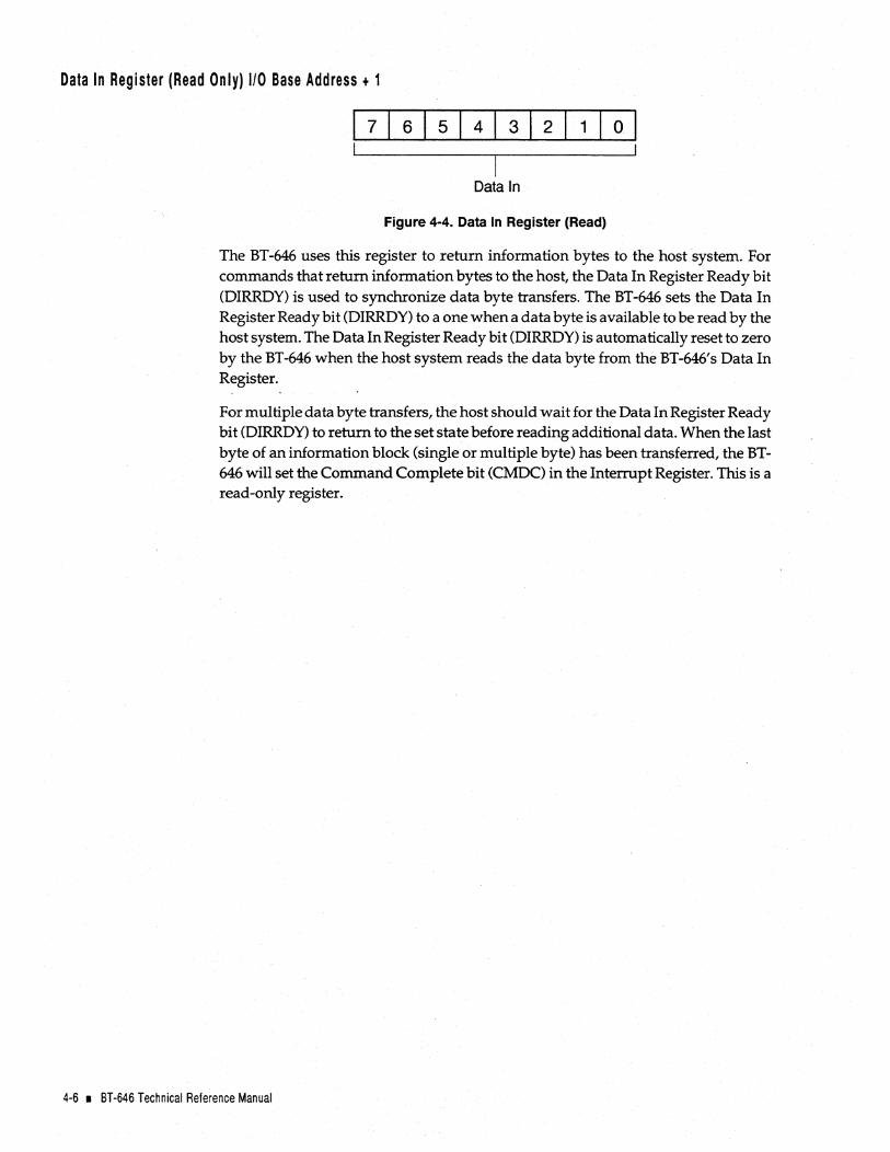
Data In Register (Read Only) 110 Base Address + 1
7 6 5 4 3 2 1 0
Data In
Figure 4-4. Data In Register (Read)
The BT-646 uses this register to return information bytes to the host system. For commands that return information bytes to the host, the Data In Register Ready bit (DIRRDY) is used to synchronize data byte transfers. The BT -646 sets the Data In Register Ready bit (DIRRDY) to a one when a data byte is available to be read by the host system. The Data In Register Ready bit (DIRRDY) is automatically reset to zero by the BT-646 when the host system reads the data byte from the BT-646's Data In Register.
For multiple data byte transfers, the host should wait for the Data In Register Ready bit (DIRRDY) to return to the set state before reading additional data. When the last byte of an information block (single or multiple byte) has been transferred, the BT-646 will set the Command Complete bit (CMDC) in the Interrupt Register. This is a read-only register.
4-6 • 8T-646 Technical Reference Manual

Interrupt Register (Read Only) I/O Base Address + 2
\ 5 4 Interrupt Valid ~ 11--_--.,.-_--'
(INTV)
ReseNed ------------~
SCSI Reset State (RSTS)
3 210 l L LJncoming Mailbox Loaded (IMBL)
Mailbox Out Ready (MBOR)
Command Complete (CMDC)
Figure 4-5. Interrupt Register (Read Only)
The BT-646 uses this read-only register to tell the host system the reason why it generated a hardware interrupt signal. The following are the four conditions under which the BT-646 can generate a hardware interrupt to the host system:
1. Incoming Mailbox Loaded interrupt (IMBL): the BT -646 has made an entry in an incoming mailbox.
2. Mailbox Out Ready interrupt (MBOR): an outgoing mailbox location(s) is ready for the host system to use.
3. Command Complete interrupt (CMDC): the BT -646 has completed a command.
4. SCSI Reset State interrupt (RSTS): the BT -646 has detected a SCSI Bus Reset condition.
When the BT -646 generates a hardware interrupt signal for one of the preceding four reasons, the BT-646 sets bits in this register to provide the host system with more information about the interrupt. The BT-646 completes the following actions:
1. It sets Bit 7, the Interrupt Valid bit (INTV), to indicate that the interrupt is valid.
2. It also sets one of the other unreserved bits to indicate why it generated a hardware interrupt signal to the host system. These bits (Bits 0-3) are collectively referred to as interrupt cause bits. This group of bits include the Incoming Mailbox Loaded bit (IMBL), the Mailbox Out Ready bit (MBOR), the Command Complete bit (CMDC), and the SCSI Reset State bit (RSTS).
In response to this interrupt request by the BT -646, the host system should execute the following sequence to service the interrupt:
1. Read the Interrupt Register. The host should maintain this value internally for further interrupt processing.
2. Clear the Interrupt Register. This is accomplished by setting the BT-646's Control Register's Reset Interrupt bit (RINT).
3. Determine the interrupt cause (from the saved Interrupt Register value in the preceding Step 1) and then execute the appropriate interrupt service routine.
Hardware Description • 4-7

Note: A hard reset, a soft reset, or initial board power-on condition will cause the Interrupt Register to be cleared, i.e., no interrupts pending.
The BT-646 sets the priority of certain interrupt conditions. This topic will be discussed before describing the individual bits of the Interrupt Register. Refer to the following heading "Interrupt Timing and Synchronization".
Interrupt Timing and Synchronization. The BT -646 sets the priority of certain interrupt conditions. The posting of a mailbox-related interrupt is withheld if a SCSI Reset State interrupt (RSTS) or a Command Complete interrupt (CMDC) is pending service from the host. Once the SCSI Reset State interrupt (RSTS) or the Command Completeinterrupt(CMDC)iscleared,theBT-646willpostthemailboxinterrupt(s). Likewise, a SCSI Reset State interrupt (RSTS) or a Command Complete interrupt (CMDC) will only be presented if the Interrupt Register has been cleared, and the Data In Ready bit (DIRRDY) shows rto additional data is pending.
Because all outbound host mailboxes are typically controlled by host-resident software, it is not necessary to enable the Outgoing Mailbox Ready interrupt (OMBR) unless all mailboxes are being utilized. This te(:hnique also lessens the possibility of missed interrupt notification for an Incoming Mailbox Loaded (IMBL) condition. If all outgoing mailboxes are in use, then the host could enable the Outgoing Mailboxes Ready interrupt (OMBR) to gain notification of a Mailbox Ready condition. See the Enable Outgoing Mailbox Ready command description in Section 5, the "Software Interface" section, for instructions on how to enable the Outgoing Mailboxes interrupts (OMBR).
Bit 0 Incoming Mailbox Loaded (IMBL)-When this bit is set, it indicates that the BT -646 has made an entry in an incoming mailbox location~ This bit is qualified by the Interrupt Valid bit (INTV) also being set and by the generation of a Micro Channel bus interrupt signal. The host should service this interrupt as soon as possible to allow additional BT-646 interrupts to be posted. The multitasking firmware of the BT -646 continues to process outstanding SCSI commands after the posting of an Incoming Mailbox Loaded interrupt (IMBL). If additional outstanding commands are completed before the servicing of a previous Incoming Mailbox Loaded interrupt (IMBL), the status of completed commands will be placed in an available incoming mailbox location. The host should therefore scan all mailboxes to determine. if additional data has been provided. The BT-646 will use Incoming Mailbox locations in a round-robin order permitting the host to scan in the same manner. When a vacant mailbox is found the host may discontinue its scan.
Bit 1 Outgoing Mailbox Ready (OMBR)-When this bit is set to a one, it indicates that one or more of the outgoing mailbox locations is available for use by the host. This bit is qualified by the Interrupt Valid bit (INTV) also being set and by the generation of a Micro Channel bus interrupt signal. The Outgoing Mailboxes Ready interrupt (OMBR) is generated only when Outgoing Mailbox interrupts (OMBR) have been enabled and an outgOing mailbox entry is cleared by the BT..:646. An Outgoing Mailbox Ready interrupt (OMBR) is suppressed if a SCSI Reset State (RSTS) or a Command Complete (CMDC) interrupt is pending service. When these previous interrupts are cleared by the host, the pending Outgoing Mailboxes Ready interrupt (OMBR) will be issued by the BT-646.
4-8 • BT-646 Technical Reference Manual
Application Note: It is recommended that the Outgoing Mailbox Ready interrupt (OMBR) not beenabled unless all outgoing mailbox locations are in use. For most applications, the BT-646 will process command requests faster than a host will issue them. If the situation does occur where all outgoing mailbox locations are busy, the host may issue the Enable Outgoing Mailbox Ready Interrupt command without waiting for the status of the Host Adapter Ready bit (HARDY).
Bit 2 Command Complete (CMDC)-This bit is set to a one when the Command/ Parameter Register is ready to accept a command. Any previous command will have been completed, either normally or abnormally. If a previous command completed with an error condition or was aborted for any reason, this bit will still be set along with the Command Invalid bit (CMDINV) in the Status Register. Normally completed commands are indicated by the setting of this bit without any accompanying error condition status bits. This bit is qualified by the Interrupt Valid bit (INTV) also being set and by the generation of a Micro Channel bus interrupt signal. A Command Complete interrupt (CMDC) is suppressed if an Interrupt Valid bit (INTV) is set (indicating an interrupt is pending service) or if the Data In Register Ready bit (DIRRDY) is set. When these previous interrupts are cleared by the host, the temporarily withheld Command Complete interrupt (CMDC) will be issued by the BT-646.
Bit 3 SCSI Reset State (RSTS)-When this bit is set, it indicates that a SCSI Bus Reset condition has been detected by the BT -646. This bit is qualified by the Interrupt Valid bit (INTV) also being set and by the generation of a Micro Channel bus hardware interrupt signal. In cooperation with Micro Channel host system driver software, the BT -646 can implement the SCSI specification soft reset option. BT-646 queued operations will resume once the SCSI bus has returned to the operational state. If a currently running command was aborted due to the SCSI Bus Reset condition, the BT-646 may have to restart the command.
The host may convert the SCSI bus soft reset to a SCSI bus hard reset by setting the Soft Reset bit (RSOFT) in the BT-646's Control Register. In this case, all queued commands are abandoned and the BT-646 must be reinitialized. See the heading "Reset Operations" later in this section for details on the reset conditions.
Bit 4 Reserved-Value read is zero.
Bit 5 Reserved-Value read is zero.
Bit 6 Reserved-Value read is zero.
Bit 7 Interrupt Valid (INTV)-When this bit is set, it indicates that a valid interrupt has been generated by the BT -646. This bit reflects the state of the BT-646 generated interrupt signal on the Micro Channel bus. The specific reason for the interrupt condition is determined by Bits 0-3 of this register.
Hardware Description I 4-9

RESET OPERATIONS
Reset conditions associated with the operation of the BT -646 are initiated from two different vantage points: the Micro Channel bus and the SCSI bus. A description of each follows.
Micro Channel Host Initiated Reset Operation
The BT-646 may be reset to an initial power-on condition through two different operations, one hardware and the other software.
Hardware Reset-The BT-646 is fully reset and initialized to a power-on initial condition when the Reset signal is true on the Micro Channel system bus. The Reset signal is asserted to a true condition by the host during power on or host detected low-power conditions. The Reset signal is applied universally to all installed host adapters in the Micro Channel system I/O channel bus.
Software Reset-The BT-646 may be fully reset to an initial state by a software command, just the same as if a hardware reset had been received. The setting of the Hard Reset bit (RHARD) will cause a Reset condition to occur immediately. This Reset condition will affect the BT-646 only, not other host adapters installed in the Micro Channel system I/O channel.
Either type of Micro Channel host initiated reset will cause the following conditions on the BT -646.
• A SCSI Bus Reset condition will be placed on the SCSI bus by the BT -646. This will reset all peripheral devices, whether a target or initiator.
• The control registers of all intelligent logic modules on the BT -646 will be initialized to a known state.
• All pending operations are aborted and all data structures are initialized to a no operation pending state.
• The BT-646 executes all internal diagnostic functions. While the diagnostic functions are in process, the BT-646 will indicate this condition by setting the Diagnostic Active bit (DACT) to true in the Status Register.
After completion of a hard reset, the BT-646 indicates that it is now in an initial condition by asserting the Initialization Required bit (INREQ) in the BT -646' s Status Register. This condition requires that all mailbox, command control blocks, and BT-646 operation parameters be established before operations may begin.
4·10 • BT·646 Technical Reference Manual

SCSI Bus Reset Operations
The SCSI Bus Reset condition is used to clear all SCSI devices immediately from the SCSI bus. When the SCSI bus Reset signal is asserted, the SCSI Bus Reset condition takes precedence over all other bus phases. A SCSI Bus Reset condition may be forced by any device on the bus, whether a target or initiator. Whenever a SCSI Reset condition occurs, a Bus Free phase always follows the Reset condition.
The four ways in which a SCSI bus reset may be either asserted or sensed by the BT-646 are as follows:
Rl The SC~I Bus Reset condition is always asserted when the BT-646 is reset by the Micro Channel host system. This is described earlier in this section under the heading "Micro Channel Host Initiated Reset Operation".
R2 If the Reset SCSI Bus bit (RSBUS) is set by the Micro Channel host system control software the BT -646 will assert the SCSI bus Reset signal on the SCSI bus. Because the host initiated this condition the SCSI Reset State bit (RSTS) in the Interrupt Register is not set.
R3 The BT -646 may initiate a SCSI Bus Reset condition in reaction to a detected bus phase error. The BT-646 constantly monitors the SCSI bus for invalid conditions. If an invalid phase is detected, the BT -646 will perform a normal SCSI Bus Reset operation which includes the assertion of the SCSI bus Reset signal. The Micro Channel host system will be notified of this condition by the generation of a Micro Channel system hardware interrupt and the setting of both the SCSI Reset State bit (RSTS) and the Interrupt Valid bit (INTV) in the ~T-646's Interrupt Register.
R4 The BT -646 will detect and respond to a SCSI Bus Reset condition that is asserted by another device on the bus. Other SCSI devices may normally assert the Reset signal during either initialization or certain error recovery states. The BT -646 will notify the Micro Channel host system of the SCSI Bus Reset condition by the generation of a Micro Channel hardware interrupt and by setting both the SCSI Reset State bit (RSTS) and the Interrupt Valid bit (INTV) in the BT-646's Interrupt Register.
The SCSI specification defines two methods by which the SCSI bus may be reset, either by the hard reset option or the soft reset option. The effect of the SCSI Bus Reset condition on uncompleted commands, SCSI device reservations, and SCSI device operating modes is determined by which method is implemented. SCSI devices must implement one of the reset options.
Hardware Description • 4-11

SCSI Bus Soft Reset Option
The BT -646 implements the soft reset option. This allows the SCSI bus to be reset, yet not destroy all initialization and configuration data in each SCSI device. The soft reset option allows a single initiator to reset the SCSI bus without disturbing the operation of other initiators in a multiple initiator system. This means that status and pointer information is not destroyed, and that disconnected or outstanding commands may be allowed to resume. The soft reset option is very useful in multiple initiator SCSI bus implementations that are typical in multiprocessor or multitasking systems. For the soft reset option to function properly, all devices on the SCSI bus must implement the option. The soft reset option performs the following:
• Attempts to complete any uncompleted command(s) that were fully identified. (See the SCSI specification for a description of "fully identified".)
• Preserves all SCSI device reservations.
• Preserves any SCSI device operating modes.
SCSI Bus Hard Reset Option
The SCSI bus hard reset option restores ALL SCSI devices, target or initiator, to the initial power-on condition. All system activity is lost, and all devices must be completely reinitialized before normal operations may be restored. SCSI· devices that implement the hard reset option perform the following operations:
• Clear all uncompleted commands.
• Release all SCSI device reservations.
• Return any SCSI device operating modes to their default condition.
The BT -646 performs only a soft reset operation If a hard reset implementation is required, the Micro Channel system may direct the BT-646 to return to a fully reset initial condition, thus implementing the hard SCSI bus reset option. This is accomplished by the following sequence:
1. Upon detection of a SCSI Bus Reset condition, the BT-646 will assert a Micro Channel hardware interrupt and will set the SCSI Reset State bit (RSTS) in its Interrupt Register. Refer to the preceding SCSI RESET descriptionR3 or R4 in the heading "SCSI Bus Reset Operations" in this section.
2. The Micro Channel host system may convert the BT -646 soft reset to a hard reset by executing a host-initiated Reset operation. The Micro Channel host system must set the Reset SCSI Bus bit (RSBUS) within 290 microseconds after the SCSI Reset State 'Qit (RSTS) has been set. This prevents the resumption of activity according to the rules of the soft SCSI reset. All BT -646 CCB's will be abandoned, and the BT-646 will ready itself to accept new initialization commands. No secondary Reset signal is generated on the SCSI bus by the BT -646. Reinitialization of all mailbox and command control blocks are required.
3. A full hard reset is required, with a secondary Reset condition generated by the SCSI bus by the BT -646, the Micro Channel host system may assert the Hard Reset bit (RHARD). This places theBT -646 in an initial power-on condition.
4·12 • BT-646 Technical Reference Manual
IIL---_____ _ SOFTWARE INTERFACE
For the BT-646 to operate properly, the Micro Channel host system must issue the. correct command and associated parameters to the BT-646. The BT-646 has its own set of executable instructions that the host system can issue to the BT-646. This command set can be subdivided into the following three groups:
1. Host adapter commands
2. Mailbox commands, and
3. BIOS commands.
The Micro Channel host system uses the host adapter commands to initialize and to establish control specifications for subsequent operations of the BT-646. The host system uses the BT-646's Command/Parameter Register as an input port through which it issues any host adapter commands and associated parameter bytes to the BT-646. For more details on each of these host adapter commands refer to the heading "Host Adapter Commands" later in this section.
The second category of commands, mailbox commands, is issued to the BT-646 when multithreading operations are required. Mailboxes are reserved storage areas which reside at a fixed contiguous memory location in the host system's main memory. The mailboxes coordinate communications between the host system and the BT-646 when the BT-646 is operating in multithreading mode. This software interface enables the BT-646 to execute multiple commands concurrently for multiple targets with minimal intervention from the host system. For more details on these mailbox commands refer to the heading "Mailbox Commands" later in this section.
The third category of commands, BIOS commands, is issued to the BT-646 when single-threaded operations are required. In this case the BIOS commands work with the BT-646's on-board BIOS. These commands in unison with the on-board BIOS function in a manner fully compatible with MS-OOS and the standard Micro Channel system BIOS interface as defined in the host system's technical reference manual. For more details on each of these BIOS commands refer to the heading "BIOS Command Interface" later in this section.
Before these commands are discussed in detail, a brief look at how the BT-646 acts as bus master to transfer data on the memory bus and how it requests interrupt service from the host is presented.
Software Interface I 5-1

Bus MASTER DIRECT MEMORY ACCESS (DMA)
As briefly described in Section I, the "Introduction" section, the DMA control logic manages bus arbitration and data transfer coordination. The BT-646 operates as a Micro Channel bus master during data transfers. The BT -646 arbitrates for Micro Channel bus access and once granted, it takes over control of the bus. It generates the Micro Channel bus address and command strobes. The BT-646 supports both odd and even starting addresses, commonly known respectively as aligned and unaligned transfers. If presented with an even transfer count beginning at an odd memory starting address, the BT-646 will first transfer a single byte (data bits D24-D3I). The remaining data is then transferred as double words (32 bits) until the last byte which is transferred as a single byte (data bits DO-D7). While odd byte data transfers are fully supported, it is recommended that when possible Micro Channel host buffers be double-word aligned to gain better data transfer performance.
During the Boot phase the BT -640' s BIOS automatically initializes the DMA controller to the correct masked condition. This automatic setup enables the BT -646 to begin normal DMA operations without any further program initialization. If other programs alter this initial DMA set up, the original masked condition can be restored
. by using either the DMA compatibility mode or the DMA extended mode. Each of these modes is described in the following two sections.
DMA Compatibility Mode
The DMA controller can be restored to its initial masked condition if the programmer sets the proper control bits using the DMA compatibility mode. The Mask Register (Set/Clear) can be used to mask the DMA controller if the program has information concerning the single DMA channel. The Write Mask Register can be used to set four of the DMA channels to the correct masked or unmasked condition simultaneously if the program has information concerning all of the DMA channels. The system's microprocessor must use 8-bit II a instructions in order to access the DMA controller.
1/0 Register Address Mask Register
. DaDA
DOOF
DOD4
DaDE
Channel 0-3, Mask Register (Set/Clear)
Channel 0-3, Write Mask Register
Channel 4-7, Mask Register (Set/Clear)
Channel 4-7, Write Mask Register
5-2 • BT-646 Technical Reference Manual

DMA Extended Mode
The definitions of the Mask Register's bits are as follows:
Register Bit
0,1
2
3-7
Bit Definition
If 00 then set/clear Channel 0 or 4 If 01 then set/clear Channel 2 or 6 If 10 then set/clear Channel 1 or 5 If 11 then set/clear Channel 3 or 7
If 0 then clear mask bit If 1 then set mask bit
RESERVED = 0
The definitions of the Write Mask Register's bits are as follows:
Register Bit
o
2
3
4-7
Bit Definition
If 0 then unmask Channel 0 or 4 If 1 then mask Channel 0 or 4
If 0 then unmask Channel 1 or 5 If 1 then mask Channel 1 or 5
If 0 then unmask Channel 2 or 6 If 1 then mask Channel 2 or 6
If 0 then unmask Channel 3 or 7 If 1 then mask Channel 3 or 7
RESERVED = 0
The following is an example of how to use the addresses of the Mask Register (Set/ Clear) to mask Channel 2:
Set the I/O address OOOA to the value 06H.
As mentioned previously in the heading "Bus Master Direct Memory Access (DMA)" the DMA extended mode can be used to restore the DMA controller to its initial mask condition. The extended mode of DMA control can be used to mask the DMA controller channels as follows. In this mode the I/O address 0018 is used as a function register. This function register is used to specify the operation that is to be performed. The 1/ 0 address 001A is used to provide additional parameters for the functions specified in the function register. In this mode, the control functions of the Mask Register do not use the I/O address 001A register.
Software Interface I 5-3

The following is the definition of bits for mask control functions executed by setting I/O address 0018:
Register Bit
0-2
3
4-7
INTERRUPT PROCESSING
Bit Definition
Channel number to which the Program Command will apply
RESERVED = a Program Command
If 9H then set specified mask bit
If AH then clear specified mask bit
If DH then clear all mask bits
Severalinterrupt channels are available to the BT -646. The channel to be used by each host adapter board is specified by configuration settings as described in Section 2, the "Unpacking and Installation" section, of this manual. The default value when only one host adapter is installed in a system is Channel 15. If additional host adapters are present in the same system, they must use different interrupt channel values.
The Micro Channel host system contains a programmable interrupt controller which receives all interrupts and directs the host's CPU to a corresponding vector location which in tum contains a memory address for the software Interrupt Service routine which performs the necessary actions required by each interrupt. It also contains a Mask Register whose bits may be set to mask or cleared to permit corresponding interrupt channels to be acknowledged.
In order to respond correctly to BT -646 interrupts during normal operation, the host interrupt controller must be programmed appropriately. The software driver will have to program the host's Interrupt Mask Register and interrupt vector before attempting to use interrupts from the BT-646. The interrupt vector locations and Interrupt Mask Register's bits which need to be cleared to permit acknowledgment of each interrupt channel are listed as follows:
Hardware Vector Location Interrupt Interrupt In Memory Mask Register Line (Hex) Hex Address A 1
IRQ9 1C4-1C7 Bit 1
IRQ10 1C8-1CB Bit 2
IRQ11 1CC-1CF Bit3
IRQ12 1D0-1D3 Bit 4
IRQ14 108-lOB Bit 6
Default IRQ15 1DC-1DF Bit 7
5-4 • BT-646 Technical Reference Manual

If the BT -646 is configured for Interrupt Channel 15, for example, the Micro Channel system's interrupt controller must be initialized by clearing Bit 7 in its Interrupt Mask Register. The address of the interrupt service routine for Channel 15 will be contained in the four bytes of memory beginning at memory address lOCH.
The remainder of this section describes the structure and operation of the three categories of commands that the host can issue to the BT-646.
HOST ADAPTER COMMANDS
Host adapter command codes and associated parameter bytes are supplied to the BT-646's Control Register under the coordination of certain bits in the BT-646's Status Register. Table 5-1 provides a summary of these commands.
Table 5-1. Host Adapter Commands
Operation Code Hex Value
00
01
02 03 04
05 06 07 08
09 OA OB OC OD 1A
1B
1C
10
1F
20 21
8D
9A
9B
Host Adapter Command
Test CMDC interrupt
Initialize Mailbox
Start Mailbox command
Start BIOS command
Inquire Board ID
Enable OMBR interrupt
Set SCSI Selection Time-Out
Set Time On Bus
Set Time Off Bus
Set Bus Transfer Rate
Inquire Installed Devices
Inquire Configuration
Set Target Mode
Inquire Set-up Information
Write Adapter Local RAM
Read Adapter Local RAM
Write Bus Master Chip FIFO
Read Bus Master Chip FIFO
Echo Data Byte
Host Adapter Diagnostic
Set Adapter Options
Inquire Extended Set-up Information
Write Inquiry Data Buffer (Target Mode Only)
Read Inquiry Data Buffer (Target Mode Only)
Software Interface I 5-5

The host system can write a command to the Command/Parameter Register only after checking to see that the Host Adapter Ready bit (HARDY) is set to one, except that the Start Mailbox command and the Enable OMBR Interrupt command may be written at any time. After writing a command, the host may write a pre~etermined number of parameter bytes to the Command/Parameter Register after checking that the CommanQ/Parameter Register Busy bit (CPRBSY) is zero, indicating that the Command/Parameter Register is not busy and can accept another parameter byte.
In response to some commands, the BT -646 may transfer a predetermined number of parameter bytes back to the host. The BT-646 places each byte into the Data In Register and then sets the Data In Register Ready bi t (DIRRDY) to indicate to the host that the byte is ready to be read by the host. After the host has read the input data byte, the BT-646 resets the Data In Register Ready bit (DIRRDY).
The following table lists each host adapter command code along with the associated number of parameter bytes coming into or being sent out from the BT -646 and a brief . description of the function performed.
Operation Code Command Parameter Byte Count Direction 00 TEST CMDC INTERRUPT None None
Description. The BT-646's only response to this command is to set the Command Complete bit (CMOC) in the Interrupt Register. When this bit is set, the host can verify proper functioning of this bit.
Operation Code Command Parameter Byte Count Direction 01 INITIALIZE MAILBOX 4 . Out
Description. This command specifies the number of mailboxes used by the BT-646, and the base memory location of the mailbox array to be used when executing mailbox commands. Four parameter bytes follow the command byte to provide the following information:
Byte Description o Number of mailboxes needed-must be greater than zero.
1-3 Base mailbox address-specifies the location of the first byte of the mailbox array. Byte 1 is the most significant byte (MSB).
Each mailbox location in memory will occupy four outgoing mailbox bytes and four incoming mailbox bytes. The Command Invalid bit (CMOINV) will be set with the Command Complete bit (CMOC) if the number of mailboxes is specified as zero. At command completion, the Command Complete bit (CMOC) is set to one and the Initialization Required bit (INREQ) is reset to zero to acknowledge that initialization is unnecessary. See the heading "Mailbox Commands" later in this section for more information on the mailbox structure.
Operation Code Command Parameter Byte Count Direction 02 START MAILBOX COMMAND None None
Description. This command is normally issued every time the host makes an outgoing mailbox entry. Upon receipt of this command, the BT-646 begins scanning for active outgoing mailbox entries and continues scanning until all outgoing mailbox entries have been serviced. This can be accomplished by either beginning the requested operations or queuing the commands and executing them later. To avoid unnecessary interrupt servicing by tne host, the Command Complete bit (CMOC) is not set after receipt of this command. If this command is received before the Initialize Mailbox command, however, the BT-646 will then set both the Command Invalid bit (CMDINV) and the Command Complete bit (CMOC) in the Status Register.
5-6 • BT-646 Technical Reference Manual

Operation Code Command Parameter Byte Count Direction 03 START BIOS COMMAND None None
Description. This command is used exclusively by the BT-646's BIOS to communicate with the BT -646's firmware. This command is not used by application programs.
Operation Code Command Parameter Byte Count Direction 04 INQUIRE BOARD ID 4 In
Description. Upon receipt of this command, the BT-646 sends four bytes of data to the host which contain identification and revision information about itself. Refer to the following byte contents:
Byte Description
o BusLogic Board Type-value allows software support for PC/AT, Micro Channel and Micro Channel Bus Logic host adapters.
Hex Value
41
42
Other
Meaning
Board is a BT-542B or BT-742A with 64-head BIOS
Board is a BT-646 with 64-head BIOS
Reserved
Custom Features-indicates what custom features may be supported by the BT-646.
Hex Value
41
Other
Meaning
Standard BT -646
Reserved
2 Firmware Revision Level-a byte designating the revision level of the BT-646 firmware. ASCII ''0''-''9"
3 Firmware Version-a byte designating the revision level of the installed firmware .
Once the four bytes of data have been transferred, the Command Complete bit (CMDC) is set indicating normal command completion.
Operation Code Command Parameter Byte Count Direction 05 ENABLE OMBR INTERRUPT 1 Out
Description. This command specifies whether the Outgoing Mailbox Ready bit (OMBR) should be set when an outgoing mailbox entry is cleared by the BT -646. The single parameter byte from the host instructs the BT -646 as follows:
Hex Value
00
01
Meaning
The Outgoing Mailbox Ready Interrupt bit (OMBR) is not to be set.
The Outgoing Mailbox Ready Interrupt bit (OMBR) is to be set once the outgoing mailbox has been cleared by the BT-646.
To avoid unnecessary interrupt servicing by the host, the Command Complete bit (CMDC) is not set after receipt of this command. If the parameter byte contains a value other than OOH or 01 H, however, the Command Invalid bit (CMDINV) is set, as well as the Command Complete bit (CMDC), to indicate receipt of an invalid command.
Software Interface I 5-7

Operation Code Command Parameter Byte Count Direction 06 SET SCSI SELECTION TIME-OUT 4 Out
Description. This command specifies the wait time used to determine whether or not a SCSI selection was successful. If the SCSI Busy signal is not returned within the specified time-out period, the selection will be terminated and the appropriate error message recorded in the returned CCB. The contents of the four parameter bytes received with this command are as follows:
Byte Description
o Enable/Disable SCSI Selection Time-Out-specifies whether or not the SCSI Selection time-out is used. Refer to the following values.
Meaning Hex Value
00 No time-out is performed.
01 The time specified in Bytes 02 and 03 is used as the SCSI time-out period.
Reserved-must be set to ~ero.
2-3 Time-Out Value--specifies the SCSI selection time-out period in milliseconds. The default value is 250 milliseconds. Byte 2 is the most significant byte.
After command completion, the Command Complete bit (CMDC) is set indicating normal command completion. The Command Invalid bit (CMDINV) is set only if data Byte 0 is invalid (neither OOH nor 01 H) or data Byte 1 is not zero which indicates an invalid command.
Operation Code Command Parameter Byte Count Direction 07 SET PREEMPT TIME ON BUS 1 O~
Description. This command specifies the time the BT -646 is allowed on the Micro Channel bus after being preempted. One parameter byte is sent to the BT -646 indicating the length of time in microseconds. This time can be from 2 to 15 microseconds. The default value is 7 microseconds. After command completion, the Command Complete bit (CMDC) is set indicating normal command completion. If the data byte value is greater than 15, the Command Invalid bit (CMDINV) is set indicating that an invalid command was received.
Operation Code Command Parameter Byte Count Direction 08 SET TIME OFF BUS 1 O~
Description. This command specifies the time the BT -646 will spend off the Micro Channel bus. One parameter byte is sent to the BT-646 indicating the length of time in microseconds. This command is treated as a np operation command. It is supported for software compatibility to ISA software.
Operation Code Command Parameter Byte Count Direction 09 SET BUS TRANSFER RATE 1 Out
Description. This command is treated as a no operation command. It is supported for software compatibility to ISA software.
5-8 • BT·646 Technical Reference Manual

Operation Code Command Parameter Byte Count 8
Direction In OA INQUIRE INSTALLED DEVICES
Description. This command asks the BT-646 to indicate the devices connected to the SCSI bus. The BT-646 issues the SCSI Test Unit Ready command to each target/Logical Unit Number (LUN) combination and reports the results using eight bytes of data returned to the host through the Data In Register. Each byte has an associated target device; Le., Byte 2 represents Target 2. If a bit has a value of one, the associated LU (Logical Unit) is installed. Each bit within a byte has an associated LU; Le., Bit 3 represents LU 3, etc.
The byte associated with the BT -646 will always be zero. Once all information has been transferred, the Command Complete bit (CMDC) is set to indicate normal command completion.
Operation Code Command Parameter Byte Count 3
Direction In OB INQUIRE CONFIGURATION
DeSCription. The BT-646 returns three bytes of data describing the host DMA channel, the interrupt channel, and the SCSIID values set during configuration set up.
The BT-646 receives these parameters through the Programmable Option Select (POS) registers. For compatibility with ISA software they can be read by the system using this command.
Byte Description Byte Description Byte Description
0 Host DMA channel Interrupt channel 2 SCSIID
Bit 0 = Reserved Bit 0 = IROO Bit 0-2 = SCSIID, binary value
Bit 1 = Reserved Bit 1 = IRQ10 Bit 3-7 = Reserved, set to zero
Bit 2 = Reserved Bit 2 = IRQ11
Bit 3 = Reserved Bit 3 = IRQ12
Bit 4 = Reserved Bit 4 = Reserved
Bit 5 = Reserved BitS = IRQ14
Bit 6 = Reserved Bit 6= IRQ1S
Bit 7 = Reserved Bit 7 = Reserved
Operation Code Command Parameter Byte Count Direction DC SET TARGET MODE 2 O~
Description. Two parameter bytes specify if the BT -646 will operate in target mode. The contents of these bytes are as follows:
Byte Description
o Specifies the SCSI operating modes the BT-646 will use. Byte values are as follows:
Hex Value
00
01
Other
Meaning
Operate as an initiator only. This is the default value after a hard reset, soft reset, or power-on reset.
Operate as both an initiator and a target SCSI device.
Invalid
Each bit of this byte is used to specify which Logical Units will respond in target mode. Only when a bit value is one will the corresponding LU be recognized as installed.
If Byte 0 contains DOH, Byte 1 is ignored. If Byte 0 contains 01 H, Byte 1 must have at least one bit set to indicate at least one LU to operate in target mode.
Software Interface • 5-9

If target mode is not specified, the BT-646 operates just like any other SCSI initiator. If target mode is not specified or if the corresponding LUN is not enabled, then the BT -646 will respond with the following: (1) a Check Condition status, (2) a Sense Code equal to 2 (Not Ready), and (3) Additional Sense. Key equal to 4 (Not Ready).
If target mode is specified but the BT -646 is busy processing another process, then the BT-646 will respond to an initiator's selection with a Busy status.
If the BT-646 does not have target mode support installed, the BT-646 will indicate that the command is invalid. If this command is issued to change from target mode to initiator only mode while there are still target mode CCB's being processed by the BT-646, the BT-646 will also respond by setting the Command Invalid status bit (CMOINV).
Operation Code Command Parameter Byte Count Direction Out 00 INQUIRE SETUP INFORMATION 1
16 In
Description. This command asks the BT -646 to provide information on its the current setup status. This command is followed by a parameter which specifies the number of bytes which the BT-646 will send to the host. The BT-646 normally transfers 16 bytes of information.
Parameter Byte
Byte Description
o Specifies the number of data bytes, from 0 to 255, to be sent to the host.
Data In Byte/Bit Assignments
Byte Description
o SCSI synchronous negotiation and parity status.
Bit
o
1
2-7
Meaning
A value of zero indicates that SCSI synchronous negotiation will not be initiated by the BT-646.
A value of one indicates that SCSI synchronous negotiation will be initiated by the BT -646 when appropriate. See the heading "Micro Channel Configuration Settings" in Section 2 of this manual for details.
A value of zero indicates that inbound SCSI transfers are not parity checked.
A value of one indicates that parity checking on inbound SCSI transfers is enabled. See the heading "Micro Channel Configuration Settings" in Section 2 of this manual for details.
Reserved (zero).
BUS TRANSFER RATE-Returns the value set by the Set Bus Transfer Rate command.
2 TIME ON BUS-Returns the time set by the Set Time On Bus command.
3 TIME OFF BUS-Indicates the time set by the Set Time Off Bus command.
4 NUMBER OF MAILBOXES-Returns the number of mailboxes established by a previous Initialize Mailbox command. If the Initialize Mailbox command has not yet been completed successfully, the returned number will be DOH.
5-10 • BT-646 Technical Reference Manual

Byte Description (Continued)
5-7 Base Mailbox Address-Returns the base address of the mailbox array established by a previous Initialize Mailbox command. The MSB is Byte 5. If the Initialize Mailbox command has not been completed successfully, these bytes have no meaning.
8 SYNCHRONOUS VALUES FOR TARGET O-Contains information resulting from synchronous negotiation with Target O. If the address is that of the BT-646 or a non-existent target, this byte will contain OOH.
Bit
0-3
7
Meaning
Contain the negotiated offset value, usually between 1 and 15.
Contain a value between 0 and 7 that defines the synchronous transfer period according to the following equation.
Period = 200 + 50 (value) nanoseconds.
Set (one) if synchronous transfer is negotiated. Reset (zero) if asynchronous transfers are used.
The following bytes have the same structure as Byte 8, but for Targets 1-7.
9 SYNCHRONOUS VALUES FOR TARGET 1
10 SYNCHRONOUS VALUES FOR TARGET 2
11 SYNCHRONOUS VALUES FOR TARGET 3
12 SYNCHRONOUS VALUES FOR TARGET 4
13 SYNCHRONOUS VALUES FOR TARGET 5
14 SYNCHRONOUS VALUES FOR TARGET 6
15 SYNCHRONOUS VALUES FOR TARGET 7
16 RETURN OF BYTE 1 OF OPCODE 21
Operation Code Command Parameter Byte Count Direction 1 A WRITE ADAPTER LOCAL RAM 3 Out
Description. The three parameter bytes contain a 24-bit address (first parameter byte is MSB) which points to a 64-byte area in the main system memory. Upon receipt of this command the BT -646 performs a bus master DMA transfer of the designated 64 bytes from the host's main memory into its own local RAM memory. Once the 64 bytes have been successfully transferred to the BT -646, the Command Complete bit (CMDC) is set indicating that this command has been completed.
Operation COde Command Parameter Byte Count Direction 1 B READ ADAPTER LOCAL RAM 3 Out
Description. The three parameter bytes contain a 24-bit address (first parameter byte is MSB) which points to a 64-byte area in the main system memory. Upon receipt of this command the BT-646 performs a bus master DMAtransfer of 64 bytes of data from its own local RAM into the designated 64 bytes in the host's main memory. Once the 64 bytes have been successfully transferred to the host's memory, the Command Complete bit (CMDC) is set indicating that this command has been completed.
Software Interface I 5-11

Operation Code Command Parameter Byte Count Direction 1 C WRrrE BUS MASTER CHIP FIFO 3 Out
Description. The three parameter bytes contain a 24.,-bit address (first parameter byte is MSB) which points to a 54-byte area in main system memory. Upon receipt of this command the BT-646 performs a bus master DMA transfer of the designated 54 bytes from the host's main memory into its own bus master chip FIFO. Once the 54 bytes have been successfully transferred to the BT -646, the Command Complete bit (CMDC) is set indicating that this command has been completed.
Operation Code Command Parameter Byte Count Direction 10 READ BUS MASTER CHIP FIFO 3 Out
Description. The three parameter bytes contain a 24-bit address (first parameter byte is MSB) which pOints to a 54-byte area in the main system memory. Upon receipt of this command the BT-646 performs a bus master DMA transfer of 54 bytes of data from its bus master chip FIFO into the designated 54 bytes in the host's main memory. Once the 54 bytes have been successfully transferred to the host's memory, the Command Complete bit (CMDC) is set indicating that this command has been completed.
Operation Code Command 1 F ECHO COMMAND DATA
Parameter Byte Count 1 1
Direction Out· In
Description. This command is used to test the Command/Parameter and Data In Registers and the associated co"ntrol bits in the remaining I/O registers. The BT -646 receives one parameter byte in the Command/Parameter Register and then instructs the host to read the same byte back from the Data In Register by setting the Data In Register Ready bit (DIRRDY). After the host has read the byte, the Command Complete bit .(CMDC) is set indicating that this command has been completed.
Operation Code Command 20 HOST ADAPTER DIAGNOSTIC
Parameter Byte Count o o
Direction Out In
Description. This command instructs the BT-646 to conduct its self-diagnostic tests. A hard reset of the BT-646 will occur without issuing a SCSI bus reset. After this command is executed, the BT -646 must be reinitialized before normal operation can continue. After issuing this command, the host should monitor the BT -646's Status Register to obtain this command's status. It should also wait until the Diagnostic Active bit (DACn of the Status Register is reset indicating that the self-diagnostics have been completed successfully. It then should wait for one or more of the following bits to be set: the Diagnostic Failure bit (DFAIL), the Host Adapter Ready bit (HARDY), or the Data In Register Ready bit (DIRRDY). If the Host Adapter Ready bit (HARDY) is set and the Diagnostic Failurebit (OFAIL) is reset, then an error did not occur during the diagnostics.
If the Diagnostic Failure bit (DFAIL) or the Data In Register Ready bit (DIRRDY) is set, then an error did occur during the diagnostics. In this case, after the Data In Register Ready bit (DIRRDY) is set, then the Data In Register should be read for the error code that will equal the number of failed diagnostic tests. No data byte is returned if there is no error. When this command is completed, the Interrupt Register will be updated as follows: the Command Complete bit (CMDC) and the Interrupt Valid bit (INTV) will be set
5-12 • BT~646 Technical Reference Manual

Operation Code Command 21 SET ADAPTER OPTIONS
Parameter Byte Count 3
Direction Out
Description. The host can use this command to specify certain configuration options for the BT-646. The host sends the specified configuration options to the BT-646 via a parameter list. This three-byte parameter list follows the command opcode. As the default, Bytes 1 and 2 of the parameter list are set. The parameter list is as follows:
Parameter Byte
Byte Description
o Specifies the number of bytes remaining in the parameter list. This specified length equals the total number of bytes in the parameter list minus one.
Disables the SCSI disconnection option. Each bit corresponds to a SCSI device (e.g., Bit 0 represents the SCSI device assigned to SCSI address 0). When the bit is set, the BT-646 will prevent the corresponding SCSI device from disconnecting. When the bit is reset, the BT -646 will allow the corresponding SCSI device to disconnect. Byte 16 of the Inquire Setup command reflects the state of this byte.
2 Disables the SCSI Busy retry option. Each bit corresponds to a SCSI device (e.g., Bit 0 represents the SCSI device assigned to SCSI address 0). When the bit is set, the BT -646 will prevent the corresponding SCSI device from being retried when the SCSI device returns a Busy status. When the bit is reset, the BT -646 will allow the corresponding SCSI device to be retried when the SCSI device returns a Busy status.
Operation Code Command 8D INQUIRE EXTENDED SETUP
INFORMATION
Parameter Byte Count 1 4
Direction Out In
Description. This command asks the BT-646 to provide information concerning its set up. This command is followed by a parameter which specifies the number of bytes which the BT-646 will send to the host. The BT-646 normally transfers four bytes of information.
Parameter Byte
Byte Description
o Specifies the number of data bytes, from 0 to 255, to be sent to the host.
Data In Byte/Bit Assignments
o ASCII code specifying host adapter bus type
"A" for PC/AT Bus
"E" for EISA Bus
"M" for Micro Channel
BIOS Address Code
C8 for OC8000H
CC for OCCOOOH
DO for ODOOOOH
D4 for OD4000H
08 for OD8000H
DC for ODCOOOH
00 for BIOS Disabled
Software Interface I 5·13

Data In Byte/Bit Assignments (Continued)
2-3 Maximum number of segments permitted in the scatter-gather list for this host adapter
Byte 2 is LSB = OOH
Byte 3 is MSB = 20H (8192)
Operation Code Command Parameter Byte Count Direction 9A WRITE INQUIRY DATA BUFFER 4 Out
Description. When the BT-646 is in target mode, it reserves a 64-byte Inquiry Data Buffer to store the Inquiry data. This command copies 64 bytes of data from the system memory into the Inquiry Data Buffer. Upon the receipt of an Inquiry command from an initiator, the Inquiry data is returned to the initiator. The actual number of bytes returned is defined by Byte 4 of the COB of the Inquiry command issued by the initiator.
Byte Description
o Byte 0 (the least significant byte) of the system memory address where the 64-byte data is to be copied from.
1 Byte 1 of the system memory address
2 Byte 2 of the system memory address
3 Byte 3 (the most significant byte) of the system memory address
Operation Code Command Parameter Byte Count Direction 9B READ INQUIRY DATA BUFFER 4 Out
Description. When the BT-646 is in target mode, it reserves a 64-byte Inquiry Data Buffer to store the Inquiry data. This command copies the contents of the Inquiry Data Buffer into the system memory.
Byte Description o Byte 0 (the least significant byte) of the system memory address where the
64-byte data is to be copied to. 1 Byte 1 of the system memory address
2 Byte 2 of the system memory address
3 Byte 3 (the most significant byte) of the system memory address
5-14 • 8T-646 Technical Reference Manual

MAILBOX COMMANDS
With today's application requirements, sophisticated operating systems, and performance capabilities of the latest systems using faster CPUs and higher bus transfer rates, it is desirable to have several different tasks running simultaneously in support of many different users. These tasks require a wide variety of I/O peripheral devices such as hard disks, tape backup units and optical drives.
One advantage offered by the SCSI bus is that up to seven I/O devices may be connected to one host adapter. An effective method is needed to manage the processing of each separate task in a system where individual users make use of many different SCSI I/O devices. A method that takes advantage of the local microprocessor, bus master ASIC, and other intelligence features of the BT-646 is needed. Otherwise, the main system CPU would be loaded down. One such method is the mailbox structure of communication between the host system and the BT -646.
Mailboxes are reserved storage areas which reside at a fixed contiguous memory location in the host system. The mailboxes coordinate communications between the host system and the BT:'646. Outgoing mailboxes are used for sending command information to the BT -646 and incoming mailboxes are used by the BT -646 to return status information about completed commands to the host or, in target mode with a CCB not available, to request CCBs from the host.
This interface architecture provides a means of passing SCSI device commands from a task, by means of a software driver, to the BT-646 in a multi-tasking, multi-user environment with minimal host intervention. In this mode the BT -646 can concurrently execute multiple commands for multiple targets. The BT-646's on-board intelligence allows it to complete bus master data transfers, to manage SCSI disconnects and reconnects and to perform other activities which reduce host intervention; thereby, increasing overall system I/O throughput. The following few pages describe the organization and operation of this approach.
Software I nterface I 5-15

MAILBOX INITIALIZATION
With most procedures in a computer system, some means of initialization must be performed to establish starting reference conditions. After power is applied to a system, many system initialization functions are carried out before any application programs are activated.
Similarly, before any mailbox commands can be supplied to the BT-646, another specific initialization process must be conducted.
First, the host system allocates storage space at a fixed contiguous location somewhere in the main system memory where the communication mailboxes will be placed. The host creates the required number of 4-byte outgoing mailboxes, followed immediately in memory by an equal number of 4-byte incoming mailboxes. The host then sends an InitializeMailboxcommandtotheBT-646.This command tel1s the BT -646 how many mailboxes will be used and the base address of the first outgoing mailbox in the main system memory as described in the heading "Host Adapter Commands" earlier in this section. There should typically be at least one set of Out/In mailboxes for each active and independent task. Figure 5-1 illustrates an array of four outgoing and four incoming mailboxes.
Mailbox Array
r········~·~·~·~:·~;~~········~
Base Mailbox ..-;.. Address :
Outgoing Mailbox 0
. Outgoing Mailbox 1
Outgoing Mailbox 2
Outgoing Mailbox 3
Incoming Mailbox 0
Incoming Mailbox 1
Incoming Mailbox 2
Incoming Mailbox 3
. . ................................ -
Figure 5-1. Mailbox Array
COMMAND CONTROL
BLOCK
,Before describing the use of outgoing and incoming mailboxes, their structure and contents will be defined.
5-16 • 8T-646 Technical Reference Manual

OUTGOING MAILBOX STRUCTURE
The following are the possible contents of the four bytes of each outgoing mailbox.
Byte Function
a Action Go de
Hex Value
00
01
02
Definition
Outgoing Mailbox is not in use
Start a Mailbox command
Abort a Mailbox command
1-3 GGB Address (Byte 1 is MSB)
The first byte of the outgoing mailbox is the "action" code. If the byte is zero in any particular outgoing mailbox, the host can place a CCB address in the last three bytes of that mailbox and set the first byte in the same mailbox to start or to abort the command contained in the designated· CCB. After the BT -646 has copied the information in an outgoing mailbox in the course of executing commands, it releases that mailbox by clearing its first byte so the host can use it again.
INCOMING MAILBOX STRUCTURE
When a CCB has been provided to the BT -646 in initiator mode or target mode, the BT -646 uses incoming mailboxes to provide information regarding the completion of the CCB to the host. The possible contents of the four bytes of each incoming mailbox of this type are as follows:
Byte Function
a Gompletion Gode
Hex Value
00
01
02 03
04
Definition
Incoming Mailbox is not in use
GGB completed without error
GGB aborted at request of host
Aborted GGB not found
GGB completed with error
1-3 GGB Address (Byte 1 is MSB)
Software I nterface I 5-17
HOST ADAPTER AS INITIATOR ON THE SCSI Bus If the first byte in an incoming mailbox is zero in any particular incoming mailbox, the BT -646 can place the address of the completed CCB in the last three bytes of that mailbox and can set the first byte in the same mailbox to indicate the manner in which the command was completed.
The format for an incoming mailbox used by the BT -646 in target mode to request a CCB will be discussed under the heading "Host Adapter Target Mode OperationCCB Not Available" later in this section.
To establish communication between the BT-646 and an attached SCSI device to execute some command, either the BT -646 or the SCSI device can initiate the SCSI command. The other party in the communication is the target. The default case is for the BT -646 to be the initiator. If the BT -646 is to be the target, however, the host must send another host adapter command to the BT -646 to Set Target Mode. The use of the mailbox architecture with the BT-646 in initiator mode will be described first.
Assuming that a task is running and that communication with a SCSI device is required the host system performs the following preparation to process the I/O request:
• Allocates an area in the main system memory for data storage or retrieval
• Creates a CCB which identifies the SCSI I/O device, provides an address which points to the data area in the main memory and specifies other detailed information about the SCSI command
• Places an address pointer to the CCB and an "action" code in an outgoing mailbox
• Sends a Start Mailbox command to the BT-646.
When the BT -646 has received the Start Mailbox command, it performs the following activities:
• Begins scanning the outgoing mailboxes to find entries with action codes using a round-robin scheme
• Copies outgoing mailbox information into its local RAM and then releases the outgoing mailbox
• Copies the CCB pointed to by the outgoing mailbox into its local RAM
• Executes the SCSI command specified in the CCB as soon as the SCSI bus is not busy.
The action taken by the BT -646 to release an outgoing mailbox once its information has been copied to local RAM depends on the host adapter command Enable OMBR Interrupt. If this command has been issued to the BT -646 to enable the Outgoing Mailbox interrupt (OMBR), the BT-646 will do one of the following:
5-18 • BT-646 Technical Reference Manual

• If no interrupt bits are set in the Interrupt Register, the BT-646 will set the Outgoing Mailbox Ready (OMBR) and the Interrupt Valid (INTV) bits in the Interrupt Register, and then will assert the Interrupt Request signal on the Micro Channel bus.
• If the Outgoing Mailbox Ready bit (OMBR) is already set to indicate that a previous outgoing mailbox was released and the interrupt was not yet cleared by the host then no additional notification to the host is required.
• If interrupts other than OutgOing Mailbox Ready interrupt (OMBR) are pending, the BT-646 will wait for all of them to be cleared before setting the Outgoing Mailbox Ready bit (OMBR).
After processing an outgoing mailbox, the BT-646 will scan for another active entry beginning with the outgoing mailbox following the one just completed. The host can ensure that the BT-646 will always find the next command with minimum overhead by placing commands in the outgoing mailboxes in consecutive, round-robin order. The BT-646 will look for additional outgoing mailbox entries until it finds an empty outgoing mailbox, at which time it will stop scanning. It will start scanning again when the host issues a Start Mailbox command to indicate that another entry has been made. Active entries are transferred into local RAM and placed in a command queue. The local RAM has enough space to store up to 32 CCBs at anyone time.
The commands are taken from the queue in a first-in first-out basis to be executed as soon as the SCSI bus is not busy. Commands will not necessarily be completed in the same order because the execution time of each command may be different.
If a Busy condition from the target device temporarily prevents the execution of a command, it is returned to the end of the queue and will be retried when queued up again. This process will continue until the Busy condition is resolved and the command can be completed.
When an outgoing mailbox is found to contain an abort code, the associated CCB pointer is used by the BT-646 to locate the mailbox command to be aborted. The designated CCB may be active or queued. If the CCB can be found the command is terminated as soon as possible. The BT -646 then makes an incoming mailbox entry to indicate that the command was terminated.
If the CCB can not be found, the command may have already been completed in a normal manner or may have been previously aborted. This situation will also be reported to the host in an incoming mailbox entry.
At the completion of each mailbox command, the target device can report that the completion was "GOOD" or that it has additional status which must be checked. In the latter case, the BT -646 may automatically issue a Request Sense command to get the additional status data from the target device. This sense data is stored in a designated area at the end of the CCB in host memory. The ability of the BT -646 to issue the Request Sense command automatically requires that Auto Sense be enabled as described in Section 2, the "Unpacking and Installation" section.
Software Interface I 5-19

At the completion of a mailbox command, the BT -646 writes status information into the BTSTAT and SDSTAT fields in the CCB in the main system memory. The BT-646 then writes into an incoming mailbox a completion status byte and a pointer to the completed CCB.
After placing an entry into an incoming mailbox, the BT-646 will take one of the following actions:
• If no interrupt bits are set in the Interrupt Register, the BT-646 will set the Incoming Mailbox Loaded (IMBL) and the Interrupt Valid (INTV) bits in the Interrupt Register and then will assert the Interrupt Request signal on the Micro Channel bus.
• If the Incoming Mailbox Loaded bit (IMBL) is already set to indicate that a previous incoming mailbox was loaded and the interrupt has not yet been cleared by the host then no additional notification to the host is required.
• If intef!Upts other ,than Incoming Mailbox Loaded interrupt (IMBL) are pending, the BT-646 will wait for all of them to be cleared before setting the Incoming Mailbox Loaded bit (IMBL).
Whenever the host sees that the Incoming Mailbox Loaded bit (IMBL) is set, it begins to scan the incoming mailboxes for active entries. The host will read each active incoming mailbox to obtain status information and pointers to the completed CCBs and then will release the incoming mailboxes for future use. When all active incoming mailboxes have been processed, the host then clears the Incoming Mailbox Loaded bit (IMBL) and the Interrupt Invalid bit (INTV) in the BT-646's Interrupt Register.
The BT-646 places no restrictions on the data segment address boundaries and lengths that are allowed. For maximum performance, however, it is recommended that all starting addresses (mailboxes, CCBs and data pointers) be on 32-bit (doubleword) boundaries and all transfer byte counts be a multiple of four.
5·20 • 8T·646 Technical Reference Manual
HOST ADAPTER IN TARGET MODE
When the Set Target Mode host adapter command is issued by the host to the BT-646 to place it in target mode, Byte 1 of the command serves as a LUN mask byte to specify which of up to eight LUNs may respond to initiator- generated SCSI commands. Seven SCSI commands may be issued from another host adapter to the BT -646 in this mode:
TEST UNIT READY
REQUEST SENSE
INQUIRY
SEND
RECEIVE
RESERVE
RELEASE.
There are also two host adapter commands that the BT-646 supports when it is in target mode. For information on the Write Inquiry Data Buffer command (9A) and the Read Inquiry Data Buffer command (9B), refer to their description in the section, "Host Adapter Commands" earlier in this chapter.
The BT -646 will respond to any other command with a Check Condition status code. Subsequent sense information provided in response to a Request Sense command from the initiator will be Illegal Request (Sense Key OSH) and Invalid Command Operation Code (Additional Sense Key 20H).
The first three of the valid commands involve no data transfers and are responded to directly by the BT -646 without the need of any CeBs. The Send and Receive commands, however, require the host to provide a CCB containing information necessary to complete the command such as the data buffer address, initiator address, LUN number and direction bits. CCBs for the Send and Receive commands may be provided to the BT -646 before the SCSI command is received or the BT-646 may request the CCBs after it receives the SCSI command.
If target mode is not specified or if the corresponding LUN is not enabled, then the BT-646 will respond with the following: (1) a Check Condition status, (2) a Sense Code equal to 2 (Not Ready), and (3) Additional Sense Key equal to 4 (Not Ready).
If target mode is specified but the BT-646 is busy processing another process, then the BT-646 will respond to an initiator's selection with a Busy status.
Software Interface I 5-21

Host Adapter Target Mode Operation-CCB Available
After issuing the Set Target Mode command to the BT-646, the host uses its knowledge of the system configuration to get ready for possible future communication to or from the BT -646. The host generates for the BT -646 two CCBs for each lUN enabled by the lUN mask byte in the Set Target Mode command and for each initiator which might transfer data to or from one of these host adapter lUNs.
One of these CCB pairs specifies a data buffer area for outgoing data from the initiator using the Send command.
The second of these CCB pairs functions as a data buffer area for incoming data to the initiator using the Receive command.
The initiator will request configuration and availability information using the Test Unit Ready, Request Sense and Inquiry commands. When it has identified the host adapter target~ it may then issue the Send and Receive commands to the selected lUN to send or to receive data packets.
The BT -646 accepts the SCSI command and transfers data into or out from the data area assigned by the appropriate CCBs. After the SCSI command is completed, the BT -646 notifies the host of the completion by posting completion information in the appropriate CCB fields, loading an incoming mailbox entry and generating the Incoming Mailbox loaded interrupt (IMBl).
Host Adapter Target Mode Operation-CCB Not Available
An initiator may attempt to issue a SCSI command to the BT -646 as a target before the required CCBs have been established by the host.
If theBT-646 has not been set to target mode, it will respond to its Target ID with a Busy status.
If the BT-646 ~s been set to target mode, it will respond to its Target ID and the Test Unit Ready, Request Sense and Inquiry commands. When it receives a Send or Receive command, however, it will obtain the IDENTIFY MESSAGE OUT to identify which lUN has been specified. It will then request the COB from the initiator and wili disconnect.
Using information from the COB, the BT-646 will then load an incoming mailbox to notify the host that a new CCB for a specific data address, length and direction must be provided. The format of the incoming mailbox when used by the BT -646 in target mode to request a CCB is as follows:
5-22 • 8T-646 Technical Reference Manual

Byte Function
o Status Code
Hex Value
10
Bits 0-2
Bit 3
Bit 4
Bits 5-7
Definition
Indicates that the host adapter in target mode received a command for which no CCB was available.
LUN number specified by the command from the Initiator.
SCSI command is a Send command. The host must prepare a CCB to transmit data from the initiator to the host adapter.
SCSI command is a Receive command. The host must prepare a CCB to transmit data from the host adapter to the initiator.
SCSI ID of initiator.
2-3 Data Length These bytes repeat the high order two bytes of the data length specified in the Send or Receive command. This informs the host that the CCB must point to a data buffer large enough to transmit this amount of data and up to 256 additional bytes.
After obtaining the information from the incoming mailbox, the host will create the requested CCB and make it available to the BT -646 by making an outgoing mailbox entry. Now having the necessary CCB, the BT-646 reconnects and completes the Send or the Receive SCSI command.
Software Interlace I 5-23

COMMAND CONTROL BLOCK STRUCTURE
A CCB contains detailed information about a SCSI command. The basis structure is presented in the following table. Detailed descriptions of each byte or field in the CCB follow this table.
COMMAND CONTROL BLOCK FORMAT
BYTE DESCRIPTION
o CCB Operation Code
Hex Value Meaning 00 Initiator CCB
01 Target CCB
02 Initiator CCB with scatter-gather
03 Initiator CCB with residual data length returned
04 Initiator CCB with scatter-gather, and residual data length returned
81 SCSI bus device reset
SCSI 10 and Direction Control
Bits 2-0 Logical Unit Number (LUN)
Bits 4-3
Bits 7-5
Specify direction of data transfer and whether data length is checked
Target 10 if an initiator CCB Initiator 10 if a target CCB
2 Length of SCSI Command Descriptor Block
3 RequeSt Sense Allocation Length/Disable Auto'Sense
4-6 Data Length (Byte 4 is MSB)
7-9
10-12
13
14
15
16-17
18-n
n-m
5-24 • 8T-646 Technical Reference Manual
Data Pointer (Byte 7 is MSB)
Link Pointer (Byte 10 is MSB)
Command Linking Identifier
BT -646 Status (BTST AT)
SCSI Device Status (SDST AT)
Reserved and set to zero
SCSI Command Descriptor Block (Length specified by Byte 2)
Reserved For Request Sense Information Bytes (Length of reserved space is specified in Byte 3)

COMMAND CONTROL BLOCK FIELD DEFINITIONS
BYTE
o
FIELD
CCB Operation
Code (Hex)
00
01
02
03
04
81
Address and Control
Bits 7-6-5
Bits 4-3
DESCRIPTION
The BT-646 acts as the initiator to issue the SCSI command specified in the COB field of the CCB to the specified target SCSI device.
The BT -646 operates in target mode and the CCB is used to service a command sent to it from another initiator. If this operation code is sent to a BT -646 that has not yet been set to target mode, the BT -646 returns a 1 AH code in the Btstat field.
The BT-646 acts as the initiator to issue a command to the specified target device in which scatter-gather data transfers are performed. In this case, the Data Length and Data Pointer fields of the CCB have a different meaning as described later in this section.
The BT-646 functions as described in the preceding operation code OOH. The only difference between operation code OOH and 03H is the updating of Bytes 4-6 (Data Length field) after the command has been completed. Refer to the description of the Data Length field later in this section for more information on this topic.
The BT-646 functions as described in the preceding operation code 02H. The only difference between operation code 02H and 04H is the updating of Bytes 4-6 (Data Length field) after the command has been completed. Refer to the description of the Data Length field later in this section for more information on this topic.
A BUS DEVICE RESET message is sent by the BT -646 to the specified target. This forces the BT-646 to abort all outstanding tasks against the selected target and to ignore all remaining CCB bytes.
Identifies the address of the devices involved in the command and provides information about the expected direction of data flow.
Specifies the target SCSI 10 if the CCB is an initiator CCB. Specifies the initiator 10 if the host adapter is in target mode.
Set to determine the direction of the data transfer as follows:
Initiator CCB
Bit Bit
4 3 Host Adapter Action
o 0 Direction of data transfer determined by the SCSI command being executed.
o Data transferred from SCSI device to host adapter. Data transfer will be a Data In phase. Data length will be checked.
o Data transferred from host adapter to SCSI device. Data transfer will be a Data Out phase. Data length will be checked.
No data transfer.
Software Interface I 5-25
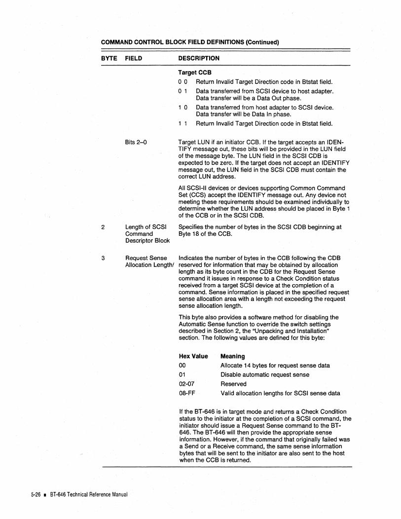
COMMAND CONTROL BLOCK FIELD DEFINITIONS (Continued)
BYTE FIELD
2
3
Bits 2-0
Length of SCSI Command Descriptor Block
Request Sense Allocation Length!
5-26 • 8T-646 Technical Reference Manual
DESCRIPTION
Target CCB
o 0 Return Invalid Target Direction code in Btstat field.
o 1 Data transferred from SCSI device to host adapter. Data transfer will be a Data Out phase.
1 0 Data transferred from host adapter to SCSI device. Data transfer will be Data In phase.
1 1 Return Invalid Target Direction code in Btstat field.
Target LUN if an initiator CCB. If the target accepts an IDENTIFY message out, these bits will be provided in the LUN field of the message byte. The LUN field in the SCSI CDB is expected to be zero. If the target does not accept an IDENTIFY message out, the LUN field in the SCSI CDB must contain the correct LUN address.
All SCSI-II devices or devices supporting Common Command Set (CCS) accept the IDENTIFY message out. Any device not meeting these requirements should be examined individually to determine whether the LUN address should be placed in Byte 1 of the CCB or in the SCSI CDB.
Specifies the number of bytes in the SCSI CDB beginning at Byte 18 of the CCB.
Indicates the number of bytes in the CCB following the CDB reserved for information that may be obtained by allocation length as its byte count in the CDB for the Request Sense command it issues in response to a Check Condition status received from a target SCSI device at the completion of a command. Sense information is placed in the specified request sense allocation area with a length not exceeding the request sense allocation length.
This byte also provides a software method for disabling the Automatic Sense function to override the switch settings described in Section 2, the "Unpacking and Installation" section. The following values are defined for this byte:
Hex Value
00
01
02-07
08-FF
Meaning
Allocate 14 bytes for request sense data
Disable automatic request sense
Reserved
Valid allocation lengths for SCSI sense data
If the BT-646 is in target mode and returns a Check Condition status to the initiator at the completion of a SCSI command, the initiator should issue a Request Sense command to the BT-646. The BT-646 will then provide the appropriate sense information. However, if the command that originally failed was a Send or a Receive command, the same sense information bytes that will be sent to the initiator are also sent to the host when the CCB is returned.

COMMAND CONTROL BLOCK FIELD DEFINITIONS (Continued)
BYTE FIELD
4-6 Data Length
7-9 Data Pointer
10-12 Link Pointer
13
14
Command Linking Identifier
Btstat
Hex Value
00
OA
OB
11
12
13
14
DESCRIPTION
Specify the byte length of the data transfer. Error code 12H is posted in the 8tstat field if a data overrun occurs. If a scattergather operation is specified by the CCB, the Data Length field contains the total number of bytes in the Data Segment List. With operation code DOH or D2H these bytes are not changed after the command is completed; however, with operation code 01 H the BT-646 will set these bytes to the actual number of bytes transferred after the command is completed. With operation codes D3H and 04H, the BT -646 will set these bytes to the difference in the data length originally specified by the host and the actual data length (number of bytes) transferred across the SCSI bus. With operation code D4H the original data length is the segment data length's sum.
Specify the real address of the first byte of the data area to be used during the data phase of a SCSI command. If a scattergather operation is specified by the CCB, the Data Pointer field contains the pointer to the first byte in the Data Segment List.
Used when a Link or Link With Tag bit is set in a SCSI command. Upon completion of a linked command, the BT -646 uses the contents of this field as a pointer to the next CCB to execute. If the Linked Flag bit is set, an interrupt will be generated before the next command is begun. A completed CCB is always reported back in an incoming mailbox. However, Incoming Mailbox interrupts (IMBL) are only reported if the linked set of commands is finished or if a Link with Flag message is presented. There must be enough incoming mailbox entries to receive the entire set of linked commands.
NOT SUPPORTED IN TARGET MODE.
Used in conjunction with linked commands. Set by the host to identify commands in a command chain.
NOT SUPPORTED IN TARGET MODE.
BT -646 status reported to the host.
CCB completed normally with no errors.
Linked command completed with no errors. The SCSI command was completed and linked with no errors.
Linked command was completed with no errors and an interrupt was generated. The SCSI command was completed and was linked with a LINKED COMMAND COMPLETE WITH FLAG message.
SCSI Selection time out. Initiator selection or target reselection did not complete within the set SCSI selection time-out period.
Data over run/under run. The target attempted to transfer more or less data than was allocated by the Data Length field or the sum of the Scatter-Gather Data Length fields.
Unexpected bus free.
An invalid bus phase or sequence was requested by the target. The BT-646 generated a SCSI Reset state, notifying the host with a SCSI Reset State interrupt (RSTS).
Software Interface I 5·27

COMMAND CONTROL BLOCK FIELD DEFINITIONS (Continued)
BYTE FIELD
15
16
17
18
19
1A
1B
1C
20
21
22
23
15 SDSTAT
1 &:-17 Reserved
18-n
n-m
SCSI Command Descriptor Block
Sense Data
5-28 • BT-646 Technical Reference Manual
DESCRIPTION
Invalid action code in Byte 0 of the outgoing mailbox.
Invalid operation code in Byte 0 of the CCB.
Linked CCB does not have the same LUN as the first CCB.
Invalid target direction in a target mode CCB.
Duplicate CCB received in target mode.
Invalid parameter in CCB or segment list.
Auto request sense failed.
SCSI-2 tagged queueing message was rejected by the target.
The host adapter hardware failed.
The target did not respond to SCSI ATN and the host adapter consequently issued a SCSI bus reset to clear up the failure.
The host adapter asserted a SCSI bus reset.
Other SCSI devices asserted a SCSI bus reset.
SCSI Device Status. If the BT-646 is the initiator, the target will send a status byte to the BT-646 at the termination of each SCSI command. The BT-646 places that status code in this byte of the CCB to report it to the host. If a Busy status is returned in the SCSI command, the command is executed a second time. The BT-646 requeues the command and automatically restarts it until the command completes with a status other than Busy.
If the BT -646 is in target mode,· it will send a status byte to the initiator at the termination of each SCSI command. The BT -646 also places that code in this byte of the CCB to inform the host what code is sent to the initiator.
Status codes reported to the initiator by the target and reported to the host in this byte may have the following values:
Hex Value
00
02
08
Status Meaning
Good
Check Condition. See CCB Byte 3 discussion of Request Sense in response to Check Condition.
Busy
Must be set to zero.
Contains the SCSI COB Its length is defined in CCB Byte 2. For initiator CCB's, the COB provided by the host is transmitted to the target. As for target mode CCB's, the COB provided from the initiator is returned to the host in this area of the CCB.
If the BT-646 detects a Check Condition status once an operation is completed on the SCSI bus, it automatically executes a Request Sense command with the number of bytes specified by the Request Sense Allocation Length in CCB Byte ' 3. The bytes returned, up to the maximum indicated by the Request Sense Allocation length, are placed in this area. If the BT-646 is operating in target mode, when a Check condition is detected by the'BT-646, the same information that will later be recovered by the initiator that received the Check Condition status is placed in this area to inform the host of the failure.

SCATTER-GATHER OPERATIONS
In normal CCB operations using SCSI Initiator (OOH) and SCSI Target (OlH) codes, the CCB contains.the pointer (CCB, Bytes 7-9) to the first byte of a contiguous area of data of a specified length (CCB, Bytes 4-6).
Unlike the preceding operation codes, the SCSI initiator with Scatter-Gather code (02H) uses CCB, Bytes 7-9 as a pointer to a list of data segments to be transferred. Bytes 4-6 in the CCB specify the length of the Data Segment List. Each entry in the list contains a three-byte field specifying the length of a data segment and a second three-byte field containing a 24-bit address which points to the corresponding data segment in host memory. The Data Segment List is arranged in the order in which data is to be "gathered" or "scattered". The first entry in the list, pointed to by the Data Segment List Pointer in CCB Bytes 7-9, will be used first. A Data Segment List can identify up to 8,192 separate segments of memory. An invalid Data Segment List error will be posted in the Btstat field (lAH) if a list contains zero or more than 8,192 segments.
The structure of the Data Segment List is as follows:
Data Segment List Pointer -
3 Bytes 3 Bytes
MSB LSB MSB LSB
Segment 0 Byte Count Segment 0 Data Pointer
Segment 1 Byte Count Segment 1 Data Pointer
Segment 2 Byte Count Segment 2 Data Pointer
Segment 3 Byte Count Segment 3 Data Pointer
Segment 4 Byte Count Segment 4 Data Pointer
Figure 5-2. Scatter-Gather
The BT-646 places no restrictions on the data segment address boundaries and lengths that are allowed. For information on 32-bit memory addressing, refer to AppendixB.
Programmer's Note: To enhance performance, it is recommended that all starting addresses (mailboxes, CCBs and data pointers) be on 32-bit (double-word) boundaries and that all transfer byte counts be a multiple of four. If an error occurs during execution of a ScatterGather command, the entire command must be retried. It is not possible to determine which segment produced the error.
Software Interface I 5·29

BIOS COMMAND INTERFACE
Micro Channel compatible systems provide for a Basic Input/ Output System (BIOS) interface in ROM on the system motherboard or on I/O option boards. These BIOS ROMs contain programs which control communication between the Disk Operating System (DOS) and the corresponding I/O peripheral device. Access to each BIOS occurs through a software interrupt of the host CPU. In the case of a hard disk, the software interrupt is Interrupt 13H.
On a standard Micro Channel system, the motherboard BIOS includes support for up to two device-level interfaced hard disks. The BIOS on the BT-646 provides equivalent support for up to two SCSI hard disks by intercepting the Interrupt 13H call and by responding to its SCSI device IDs. Control of any additional hard disk drives requires the use of a software driver using mailbox commands.
If two standard hard disks are present in a Micro Channel system, the BT -646' s BIOS cannot support additional SCSI drives without a software driver. If no standard hard disks are installed, the BT -646' s BIOS can support up to two SCSI hard disks. In this case, Drive ° (C:) is Device 0, LUNO. Drive 1 (D:) is SCSI Device 1, LUNO. Booting can only be done from SCSI Device 0, LUNO.
If one standard hard disk is installed, it is accessed as Drive ° (C:). The system may be booted only from this internal hard disk. One SCSI hard disk may be concurrently supported by the BT-646. Its identity is Device 0, LUNO (D:).
Parameters required to execute commands associated with the control of the hard disks are transferred to and from the BIOS program routines with the use of the host CPU's general registers and segment registers. This interface is capable only with single-threaded operation.
The BT -646' s BIOS can accept functions from the M5-DOS operating system that are required for normal operation, system booting, basic maintenance and verification functions.
The BT-646 is notified by its on-board BIOS when Interrupt 13H operations are in process by the Start BIOS host adapter command (03H). The BT -646 will not respond properly to the Start BIOS command if it is issued by any other source than the onboard BIOS.
BIOS Commands and Input Parameters
The BIOS command code is passed to the BT-646 through the CPU's Register AH. The drive number is provided to the BT-646 through the CPU's Register DL. The drive number for each command will be SOH or SIH. Refer to the following table for a summary of valid BIOS disk functions. Other input parameters required by the BT-646 to execute some of these commands will be described following the table.
5·30 • BT·646 Technical Reference Manual

Valid BT-646 BIOS Disk Functions
Command Code in AH Register (Hex Value) Command
00 Reset Disk System
01 Read Status of Last Operation
02 Read Desired Sectors Into Memory
03' Write Desired Sectors From Memory
04 Verify Desired Sectors
06 Identify SCSI Devices
08 Read Drive Parameters
09 Initialize Drive Pair Characteristics
DC Seek
00 Alternate Disk Reset
10 Test Drive Ready
11 Recalibrate
Description
The BIOS issues a reset to the SCSI bus.lt then sends this command on to the standard Micro Channel BIOS so it can reset other floppy or hard disks in the system.
The BT-646 reports the status of the last operation performed by the specified disk. No SCSI activity occurs and the disk status is reset to zero.
The requested sectors, defined by the input parameters, are read from the disk to the system memory. This function maps to a SCSI Read command (SCSI Opcode 08).
The requested sectors, defined by the input para-meters, are written from the system memory to the indicated disk. This function maps to a SCSI Write command (SCSI Opcode OA).
The requested sectors, defined by the input param-eters, are verified to be written correctly on the SCSI disk. This function maps to a SCSI Verify Command (SCSI Opcode 2F). In some special cases, for targets that do not support the 2F command, this function maps to a SCSI Read command (SCSI Opcode 08) and discards the received data.
This command is used to determine the number of the first SCSI drive attached to the BT-646.
This function maps to a SCSI Read Capacity com-mand (SCSI Opcode 25). The total logical capacity is then converted to pseudo-physical parameters.
Because SCSI CCS drives are self-configuring, this command performs no operation.
This function performs a Seek command (SCSI Opcode DB) to the logical block address as defined by the physical parameters. This command is not required for CCS commands nor for proper SCSI device operations. Because the Seek operation is performed automatically by the Read and Write operations, it is not necessary to generate a Seek command to access data.
The BIOS sends a SCSI bus reset to the target specified in the DL Register. A reset function request is also passed to the system's BIOS so that any internally installed hard or floppy disk(s) can be reset.
This function maps to a SCSI Test Unit Ready command (SCSI Opcode 00). After executing a Reset function, the BT-646's BIOS issues this function internally until the Target is no longer busy and the Unit Attention condition is cleared.
This function maps to a Re-zero Unit command (SCSI Opcode 01).
Software Interface I 5-31
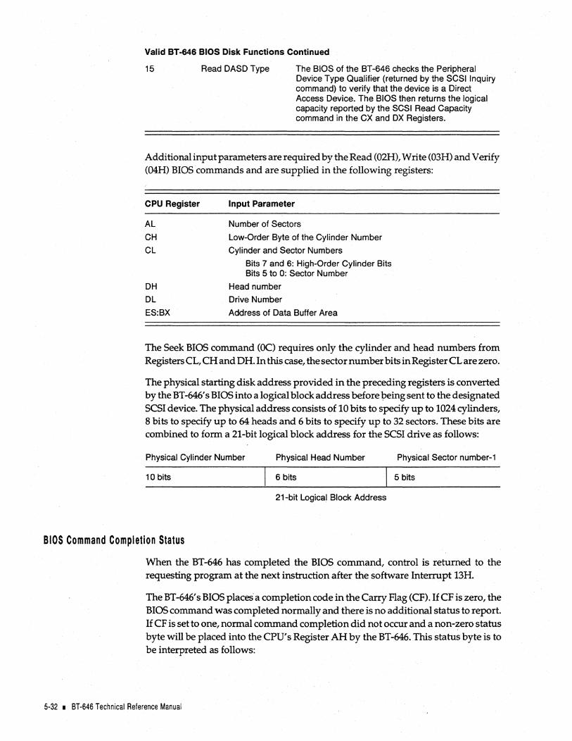
Valid BT-646 BIOS Disk Functions Continued
15 Read DASD Type The BIOS of the BT-646 checks the Peripheral Device Type Qualifier (returned by the SCSI Inquiry command) to verify that the device is a Direct Access Device. The BIOS then returns the logical capacity reported by the SCSI Read Capacity command in the CX and OX Registers.
Additional input parameters are required by the Read (02H), Write (03H) and Verify (04H) BIOS commands and are supplied in the following registers:
CPU Register
AL
CH
CL
DH
DL
ES:BX
Input Parameter
Number of Sectors
Low-Order Byte of the Cylinder Number
Cylinder and Sector Numbers
Bits 7 and 6: High-Order Cylinder Bits Bits 5 to 0: Sector Number
Head number
Drive Number
Address of Data Buffer Area
The Seek BIOS command (OC) requires only the cylinder and head numbers from Registers CL, CH and DH. In this case, the sector number bits in Register CL are zero.
The physical starting disk address provided in the preceding registers is converted by the BT -646' s BIOS into a logical block address before peing sent to the designated SCSI device. The physical address consists of 10 bits to specify up to 1024 cylinders, 8 bits to specify up to 64 heads and 6 bits to specify up to 32 sectors. These bits are combined to form a 21-bit logical block address for the SCSI drive as follows:
Physical Cylinder Number Physical Head Number Physical Sector number-1
10 bits 6 bits 5 bits
21-bit Logical Block Address
BIOS Command Completion Status
When the BT-646 has completed the BIOS command, control is returned to the requesting program at the next instruction after the software Interrupt 13H.
The BT -646' s BIOS places" a completion code in the Carry Flag (CF).1f CF is zero, the BIOS command was completed normally and there is no additional status to report. If CF is set to one, normal command completion did not occur and a non-zero status byte will be placed into the CPU's Register AH by the BT -646. This status byte is to be interpreted as follows:
5-32 • 8T-646 Technical Reference Manual

Completion Hex Sense Code Returned Status Byte To The BT-646 From The Hex Value Meaning Request Sense Command
00 No error. Normal Completion.
01 Invalid Command Request
02 Address Mark Not Found 12-No AM Found on Disk 21-lIIegal Logical Block Address
03 Write Protect Error 27-Write Protected
04 Read Error 14-No Record Found 16-Data Sync Error
10 Uncorrectable ECC Error 10-10 ECC Error 11-Unrecovered Read Error
11 ECC Corrected Data Error 17-Recovered Read Error wlo ECC 18-Recovered Read Error wi ECC
20 Controller Failure or one 01 03 05 06 07 of many Additional Sense 08 09 1B 1C 10 Codes was returned 40-49
40 Seek Operation Failed 15-Seek Positioning Error 02-No Seek Complete
80 Selection Time-Out Drive did not respond to host adapter
AA Device Not Ready 04-LUN Not Ready 28-Medium Changed 29-Power On or Reset or Bus Device
Reset Occurred 2A-Mode Select Parameter Changed
BB Unknown Target Sense Error Unknown Additional Sense Code from SCSI Device
FF Sense Operation Failed No sense information from
Additional output parameters are required by three BIOS commands and are supplied in the following CPU registers:
Command CPU (HEX) Register Output Parameter
06 AL Drive Number of First SCSI Drive Attached Identify SCSI Devices 80 if no standard hard disk
81 if one standard hard disk
08 DL Number of SCSI Drives Attached Read Drive Parameters DH Max value for head number (3F)
CH Max value for Cylinder Range (Low Byte) CL Max value for Sector and Cylinder
Bits 7-6 High Order Cylinder Bits Bits 5-0 Max Sector Number (20)
15 AH Status of Operation Read DASD 00 Drive not present or DL invalid
01 Reserved 02 Reserved 03 Fixed Disk installed
CX,DX Number of 512 byte blocks available on disk
Software Interface I 5-33

BIOS DISK COMMANDS
The BT -646' s BIOS can accept functions from the MS-OOS operating system that are required for normal operation, system booting, and normal disk operation, basic maintenance and verification functions. Refer to the following table for a summary of valid BIOS disk functions. Detailed explanations of the operation of each BIOS command follow the table.
Valid BIOS Disk Functions
Command Value in AH Register (Hex Value)
00
01
02 03 04
06 08 09 OC OD 10
11
15
Description
Reset Disk System
Read Status of Last Operation
Read Desired Sectors to Memory
Write Desired Sectors from Memory
Verify Desired Sectors
Identify SCSI Devices
Read Drive Parameters
Initialize Drive Pair Characteristics
Seek
Alternate Disk Reset
Test Drive Ready
Recalibrate
Read DASD Type
In the following descriptions, all references to the SCSI operation codes or parameters input from the host and output back to the host through the various CPU registers are stated in their Hex value for each BIOS command.
Oo-Reset Disk System. The BIOS issues a reset to the SCSI bus. It then sends this command on to the standard Micro Channel BIOS so it can reset other floppy or hard disks in the system.
Input Parameters: AH=OOH
DL=Drive Number (80H or 81H)
Output Parameters: AH=Status of Operation
CF=Return Code
Ol-Read Status of Last Operation. The BT-646 reports the status of the last operation performed by the Specified disk. No SCSI activity occurs and the disk status is reset to zero.
Input Parameters: AH=Ol
DL=Drive Number (SOH or 81H)
Output Parameters: AH=Status of Operation
CF=Completion Code
5·34 • BT·646 Technical Reference Manual

02-Read Desired Sectors to Memory. The requested sectors, defined by the input parameters, are read from the disk to the system memory. This function maps to a SCSI Read command (SCSI Opcode OS).
Input Parameters: AH=02H
DL=Drive Number (SOH or SIH)
DH=Head Number
CH=Low-order Byte of Cylinder Number
CL=High-cylinder Bit and Sector Numbers
AL=Number of Sectors to Read
ES:BX=Address of Data Buffer Area
Output Parameters: AH=Status of Operation
CF=Completion Code
03-Write Desired Sectors from Memory. The requested sectors, defined by the input parameters, are written from the system memory to the indicated disk. This function maps to a SCSI Write command (SCSI Opcode OA).
Input Parameters: AH=03H DL=Drive Number (BOH or BIH)
DH=Head
CH=Low-order Byte of Cylinder Number
CL=High-cylinder Bit and Sector Numbers
AL=Number of Sectors to Write
ES:BX=Address of Buffer Area
Output Parameters: AH=Status of Operation CF=Return Code \
04-Verify Desired Sectors. The requested sectors, defined by the input parameters, are verified to be written correctly on the SCSI disk. This function maps to a SCSI Verify command (SCSI Opcode 2F). In some special cases, for targets that do not support the SCSI Verify command, this function maps to a SCSI Read command (SCSI Opcode OS) and discards the received data.
Input Parameters: AH=04H DL=Drive Number (SOH or SIH)
DH=Head
CH=Low-order Byte of Cylinder Number
CL=High-cylinder Bit and Sector Numbers
AL=Number of Sectors to Verify
ES:BX=Address of Buffer Area
Output Parameters: AH=Status of Operation
CF=Completion Code
Software Interface I 5-35

06-Identify SCSI Devices. This command is used to determine the number of the first SCSI drive attached to the BT-646.
Input Parameters: AH=06
Output Parameters: AH=Status of Operation
AL= Drive Number of First SCSI Drive Attached
80H if no standard hard disk
8tH if one standard hard disk
CF=Completion Code
OB-Read Drive Parameters. This function maps to a SCSI Read Capacity command (SCSI Opcode 25). The total logical capacity is then converted to pseudo-physical parameters.
Input Parameters: AH=08H
DL=Drive Number (80H or 81H)
Output Parameters: AH=Status of Operation
DL=Number of SCSI Drives Attached
DH=Max value for head number (3Fh)
CH=Max value for Cylinder Range (Low Byte)
CL=Max value for Sector and Cylinder
Bits 7-6 High-order Cylinder Bits
Bits 5-0 Max Sector Number (20h)
CF=Completion Code
09-Initialize Drive Pair Characteristics. Because SCSI CCS drives are self-configuring, this command performs no operation.
Input Parameters: AH=09H DL=Drive Number (80H or 81H)
Output Parameters: AH=Status of Operation
CF=Completion Code
~C-Seek. This function performs a Seek operation (SCSI Opcode OB) to the logical block address as defined by the physical parameters. This command is not required for CCS commands nor for proper SCSI device operations. Because the Seek operation is performed automatically by the Read and Write operations, it is not necessary to generate a Seek command to access data. If the addressed device reports that the Extended Seek command is not supported, the BIOS command will be completed as normal.
Input Parameters:
5·36 • BT·646 Technical Reference Manual
AH=OCH
DL=Drive Number (80H or 8tH)
DH=Head
CH=Cylinder
CL=High Cylinder (Sector bits=O)
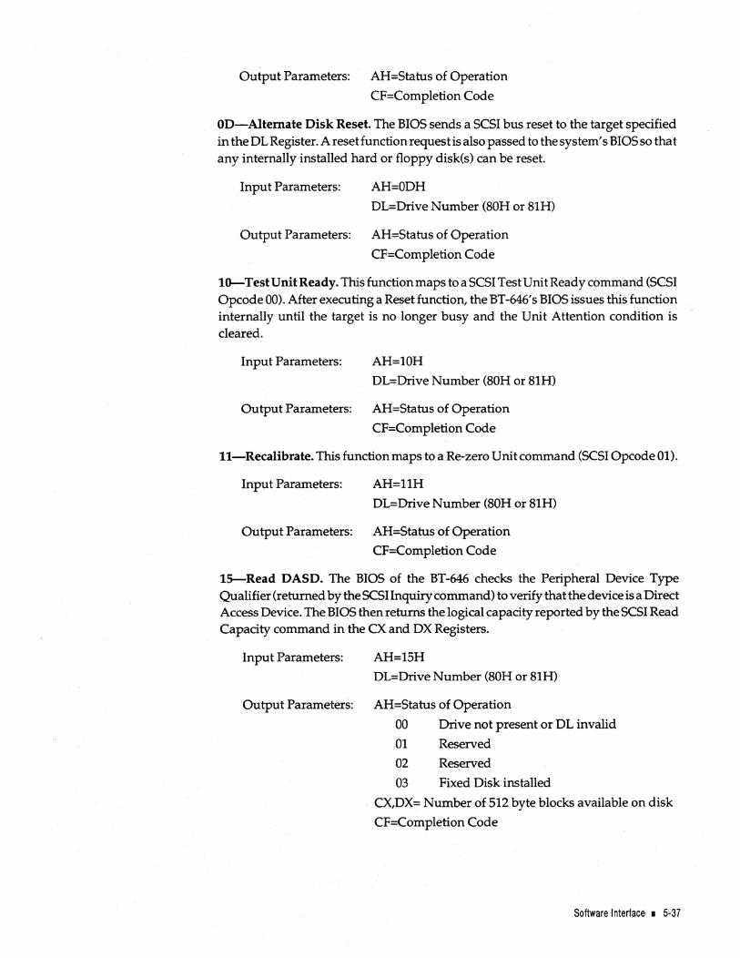
Output Parameters: AH=Status of Operation
CF=Completion Code
OD-Alternate Disk Reset. The BIOS sends a SCSI bus reset to the target specified in the DL Register. A reset function request is also passed to the system's BIOS so that any internally installed hard or floppy disk(s) can be reset.
Input Parameters: AH=ODH
DL=Drive Number (80H or 81H)
Output Parameters: AH=Status of Operation
CF=Completion Code
10-Test Unit Ready. This function maps to a SCSI Test Unit Ready command (SCSI Opcode 00). After executing a Reset function, the BT -646's BIOS issues this function internally until the target is no longer busy and the Unit Attention condition is cleared.
Input Parameters: AH=lOH DL=Drive Number (80H or 81H)
Output Parameters: AH=Status of Operation
CF=Completion Code
ll-Recalibrate. This function maps to a Re-zero Unit command (SCSI Opcode 01).
Input Parameters: AH=l1H
DL=Drive Number (80H or 81H)
Output Parameters: AH=Status of Operation
CF=Completion Code
1S-Read DASD. The BIOS of the BT-646 checks the Peripheral Device Type Qualifier (returned by the SCSI Inquiry command) to verify that the device is a Direct Access Device. The BIOS then returns the logical capacity reported by the SCSI Read Capacity command in the CX and DX Registers.
Input Parameters: AH=15H DL=Drive Number (80H or 81H)
Output Parameters: AH=Status of Operation
00 Drive not present or DL invalid
01 Reserved
02 Reserved
03 Fixed Disk installed
. CX,DX= Number of 512 byte blocks available on disk
CF=Completion Code
Software Interface I 5·37

5-38 • BT-646 Technical Reference Manual

BT·646 INTERNAL DIAGNOSTICS
When power is first applied to the BT-646, an on-board diagnostic routine is run to verify that the major functional components of the board are operating correctly. The bus master chip, the SCSI controller chip, the firmware PROM, the local RAM and internal data buses are tested. Results of the tests are indicated by an LED on the board.
The LED will first turn on when power is applied. If the diagnostics find no malfunctions, the LED will then go off. In normal operation, the LED will be illuminated when command or SCSI bus activity occurs on the board.
If an error is detected by the diagnostics, the LED will repeatedly flash a specific number of times, with a long pause between flashes, to indicate the board function which failed. This will continue until the board is powered down or reset. Failure interpretation from the number of flashes is as follows:
Number of LED Flashes
Always On
1
2
3
4
5
6
7
Constantly Flashing
Interpretation of Failure
BT -646 is not operating or terminators are missing
Firmware ROM checksum failure
Local RAM test failure
SCSI controller chip or SCSI interface failure
Internal data bus failure
Internal address bus failure
Bus master chip failure
SCSI drive type mismatch*
Fuse Blown.
*This error message is applicable to the BT-646 when single-ended SCSI drives are connected to the differential SCSI bus.
BT-646 Internal Diagnostics • A-1

A-2 • BT-646 Technical Reference Manual
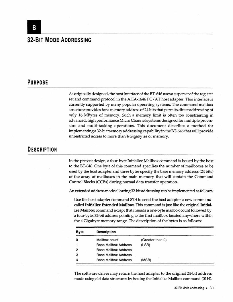
11<-----____ -32·BIT MODE ADDRESSING
PURPOSE
DESCRIPTION
As originally designed, the host interface of the BT -646 uses a superset of the register set and command protocol in the AHA-1646 PCI AT host adapter. This interface is currently supported by many popular operating systems. The command mailbox structure provides for a memory address of 24 bits that permits direct addressing of only 16 MBytes of memory. Such a memory limit is often too constraining in advanced, high performance Micro Channel systems designed for multiple processors and multi-tasking operations. This document describes a method for implementing a 32-bit memory addressing capability in the BT -646 that will provide unrestricted access to more than 4 Gigabytes of memory.
In the present design, a four-byte Initialize Mailbox command is issued by the host to the BT -646. One byte of this command specifies the number of mailboxes to be used by the host adapter and three bytes specify the base memory address (24 bits) of the array of mailboxes in the main memory that will contain the Command Control Blocks (CCBs) during normal data transfer operation.
An extended address mode allowing 32-bit addressing can be implemented as follows:
Use the host adapter command 81H to send the host adapter a new command called Initialize Extended Mailbox. This command is just like the original Initialize Mailbox command except that it sends a one-byte mailbox count followed by a four-byte, 32-bit address pointing to the first mailbox located anywhere within the 4 Gigabyte memory range. The description of the bytes is as follows:
Byte Description
0 Mailbox count (Greater than 0) 1 Base Mailbox Address (LSB)
2 Base Mailbox Addr~ss
3 Base Mailbox Address 4 Base Mailbox Address (MSB)
The software driver may return the host adapter to the original 24-bit address mode using old data structures by issuing the Initialize Mailbox command (01H).
32-8it Mode Addressing I 8·1
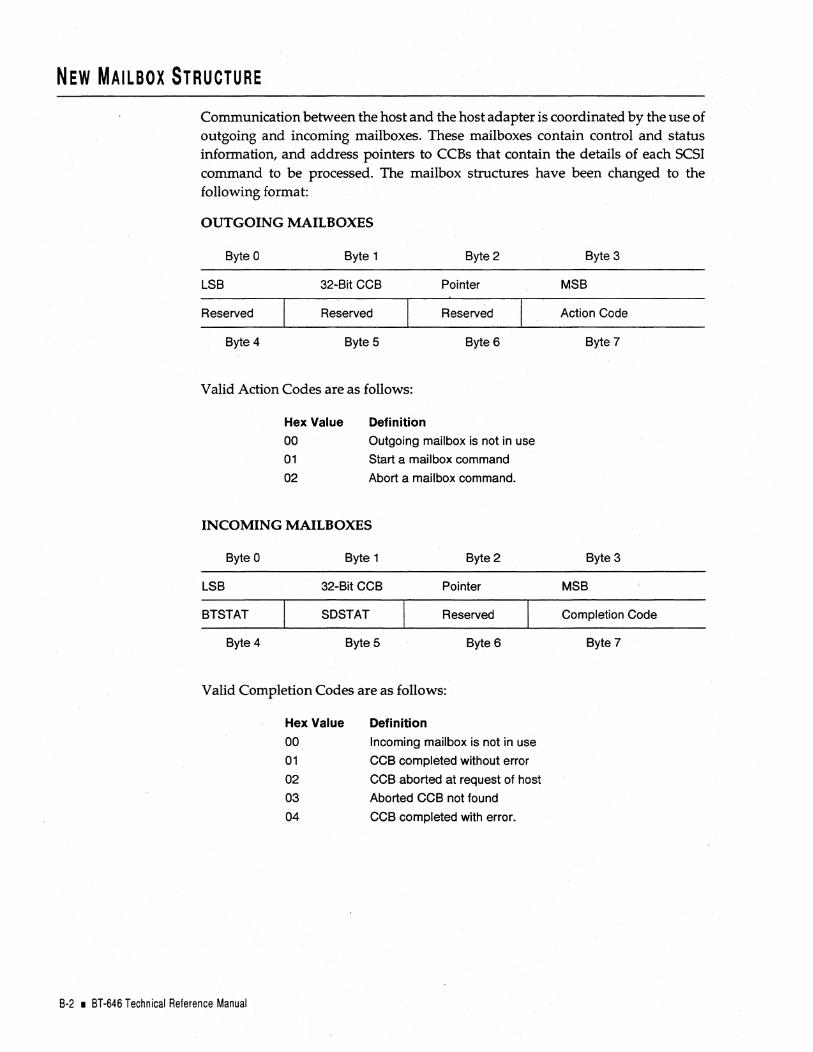
NEW MAILBOX STRUCTURE
Communication between the host and the host adapter is coordinated by the use of outgoing and incoming mailboxes. These mailboxes contain control and status information, and address pointers to CCBs that contain the details of each SCSI command to be processed. The mailbox structures have been changed to the following format:
OUTGOING MAILBOXES
Byte 0 Byte 1 Byte 2
LSB 32-Bit CCB Pointer
Reserved Reserved Reserved
Byte 4 Byte 5 Byte 6
Valid Action Codes are as follows:
Hex Value
00 01
02
Definition
Outgoing mailbox is not in use
Start a mailbox command
Abort a mailbox command.
INCOMING MAILBOXES
Byte 0 Byte 1 Byte 2
LSB 32-Bit CCB Pointer
BTSTAT SDSTAT Reserved
Byte 4 Byte 5 Byte 6
Valid Completion Codes are as follows:
B-2 • BT-646 Technical Reference Manual
Hex Value
00
01
02
03
04
Definition
Incoming mailbox is not in use
CCB completed without error
CCB aborted at request of host
Aborted CCB not found
CCB completed with error.
Byte 3
MSB
Action Code
Byte?
Byte 3
MSB
Completion Code
Byte?

NEW CCB STRUCTURE
Byte Description
o Operation Code
Data Direction Control
2 Length of CDB
3 Length of Sense Area
4 LSB
5 Data
6 Length
7 MSB
8 LSB
9 Data
10 Pointer
11 MSB
12 Reserved
13 Reserved
14 BTSTAT
15 SDSTAT
16 Target ID
17 LUN & Tag
18-29 Command Descriptor Block
(12 Bytes)
30 CCB Control
31 Link ID
32 LSB
33 Link
34 Pointer
35 MSB
36 LSB
37 Sense
38 Pointer
39 MSB
Note: In the extended address mode, Bits 3 and 4 of Byte 1 (the Data Direction Control byte> are used as in standard mode. Bits 0-2 and 5-7, however, are reserved in extended mode.
Note that all reserved bytes and bits should always be set to zero.
32-Bit Mode Addressing I B-3

NEW eeB DESCRIPTION
Many fields of this new CCB are identical to the original CCB. Data address fields have been expanded to four-byte fields to contain full 32-bit address pointers. The byte order has been reversed, with the LSB coming first rather than the MSB. To enhance symmetry, the Data Length field has been expanded to four bytes as well.
The BTSTAT (BT-646 status) field contains host adapter status information at the completion of a SCSI command. In this new proposal, the contents of this field are written by the host adapter into the incoming mailbox as well as back into theCCB in the main memory to give the host the option of not having to access the CCB again for completion status.
The SDSTAT (SCSI device status) field contains status information from the target SCSI· device at the completion of the SCSI command. In this new proposal, the contents of this field are written by the host adapter into the incoming mailbox as well as back into the CCB in the main memory to give the host the option of not having to access the CCB again for completion status.
Target 10 and LUN numbers have been given their own bytes rather than having to share a byte with specification of data direction and length checking in Byte 1 of the CCB.
A Sense Pointer has been included. This offers the option of allocating a storage area anywhere in the main memory for the information returned in response to a Request Sense command. One option is to have the Sense Pointer point to the bytes immediately following itself at the end of the CCB; Refer to the following table for a description of the byte or field in this new CCB.
COMMAND CONTROL BLOCK FIELD DEFINITIONS
BYTE FIELD
14 BTSTAT
B-4 • BT-646 Technical Reference Manual
DESCRIPTION
New status available.
Value Description
1 B Auto Request Sense failed. 1 C A SCSI II Tagged Queuing message was rejected by the
Target. 20 The host adapter hardware failed. 21 The Target did not respond to SCSI ATN so the host
adapter issued a SCSI RST to clear up the failure. 22 The host adapter asserted SCSI RST. 23 Other SCSI devices asserted SCSI RST. 24 The target device reconnected improperly (without tag).
An Abort message was issued. 25 The host adapter issued BUS DEVICE RESET. 26 Abort Queue generated.

COMMAND CONTROL BLOCK FIELD DEFINITIONS (Continued)
BYTE FIELD DESCRIPTION
17 Logical Unit Number
(LUN) and Tag
Bits 2-0
Bits 4-3
Bit 5
6,7
30 CCB Control
Specifies the Logical Unit Number (LUN).
Reserved.
Tag enable. When this bit is set, the host adapter will support the tag queueing feature according to the SCSI-2 specifications. When this bit is reset, the host adapter will not support this feature.
Specifies the tag type. These two bits have no meaning if bit 5 (the Tag Enable bit) is not set. When bit 5 is set, bits 6 and 7 have the following meaning:
Bit7 o o
Bit6 o 1 o
Message to be sent to the target after IDENTIFY Simple Queue Tag (20H) + Unique Tag ID Head of Queue Tag (21 H) + Unique Tag ID Ordered Queue Tag (22H) + Unique Tag ID
Reserved (Do not use this value.)
NOT SUPPORTED IN TARGET MODE.
Bit
Bits 2-0
Bit 3
Bit 4
Bit 5
Bit 6
Name
No Disc
NoUnd
NoData
NoStat
Description when the bit is set to 1
Reserved.
No disconnect. When this bit is set, the host adapter will select the target with IDENTIFY MESSAGE byte value SOH which will disallow the target from disconnecting the current selection. When this bit is reset, the host adapter will act according to the value of the host adapter command 21 H's (Set Adapter Options command) Byte 1. If that value is not programmed it will always allow disconnect.
No underrun error report. When this bit is set, the host adapter will not report a data overrun/underrun error (BTSTAT value 12H). If this bit is reset, the host adapter will report a data overrun/underrun error whenever the count of the data transfer between the target and the host differs from the count specified in the CCB data count bytes and/or the combined scatter-gather count. The residual count will be posted in the CCB data counts bytes if the CCB opcode is 03 or 04.
No data transfer. When this bit is set, the host adapter will not transfer any data between the host adapter and host memory. If this bit is reset, the host adapter will transfer data between the host adapter and host memory.
No CCB status if zero. When this bit is set, the host adapter will not update any CCB status byte if the status to be reported is zero. If this bit is reset, all status bytes will be updated. This bit can be used for performance improvement.
32-8it Mode Addressing I 8-5

COMMAND CONTROL BLOCK FIELb DEFINITIONS (Continued)
BYTE FIELD DESCRIPTION
Bit
Bitl
Name
Nolntr
Description when the bit is set to 1
No interrupts. When this bit is set, the host adapter will not interrupt the host after a command is completed. If this bit is reset, the host adapter will interrupt the host after a command is completed.
NOT SUPPORTED IN TARGET MODE
SCATTER-GATHER OPERATION
Within the current design when a scatter-gather data transfer is performed, the CCB points to a list of the separate data segments involved in the transfer. This list contains a three-byte field specifying the length of each individual data segment and a second three-byte field containing a 24-bit address that points to the corresponding data segment.
With extended addressing, the scatter-gather list must be expanded to pairs of fourbyte fields for each data segment in place of the present pairs of three-byte fields. These 32-bit addresses provide unrestricted access to any area of the 4 Gigabyte memory space. The structure of the expanded data segment list is as follows:
Scatter-Gather Data Segment List
4 Bytes
LSB MSB
CCB Bytes 8-11 Segment List Pointer -> Segment 0 Byte Count
Segment 1 Byte Count
Segment 2 Byte Count
Segment 3 Byte Count
Segment 4 Byte Count
4 Bytes
LSB MSB
Segment 0 Data Pointer
Segment 1 Data Pointer
Segment 2 Data Pointer
Segment 3 Data Pointer
Segment 4 Data Pointer
In the BusLogic implementation of the BT-646, such a data segment list can have from 1 to 8192 segments.
8-6 • BT-646 Technical Reference Manual

COMMAND QUEUING
The BT-646 now supports command queuing. The following are some device driver notes related to command queuing.
1. Once a device queues up Tag Queue commands, the Initiator should not issue a Non-Tag Queue command (with the exception of Contingent Allegiance condition) until all queued commands have been processed. Therefore, avoid mixing Tag Queue commands with Non-Tag Queue commands.
2. If a CCB is aborted in a Tag queue environment, the host adapter can no longer issue an Abort message to the target. It will have to wait until the Target reestablishes the CT_L_Q NEXUS. Consequently, it is recommended thataCCB not be aborted in a Tag Queue environment.
3. When a Bus Device Reset is issued, the Target will flush all queued I/O commands. Consequently, the host adapter must return SCSI Reset status for all the CCBs sent to the Target.
4. When a SCSI Bus Reset is issued, all Targets will flush all queued I/O commands. Note that the host adapter will flush all existing TCB in the Disconnect TCB Link Ust and the Abort TCB Link List. Consequently, the host adapter must return SCSI Reset status for all the CCBs sent out.
5. If there are any outstanding Tag Queue commands and a Target attempts to reconnect without a Tag message, the host adapter will generate an Abort message. The host adapter will flush all outstanding CCBs sent to that Target. All these CCBs will be returned to the host with Host Adapter Status 24H. Refer to the description of the BTSTAT field in this appendix for new host adapter status.
6. Because a Tag message must be sent right after an 10 message, synchronous transfer negotiation initiated by the Initiator takes precedence over a Tag Queue message. This is because most devices that support Tag Queuing may not be able to handle an ID message, followed by a Tag Message, followed by a Synchronous Transfer Negotiations message.
Consequently, it is recommended that the first couple of commands be sent in Non-tag Queue fashion. This will allow the host adapter and Target to establish Synchronous Transfer mode after each Reset condition.
7. The Auto Sense capability is a useful feature that can be enabled or disabled. If Auto Sense is enabled and a Contingent Allegiance condition occurs, the host adapter will issue a Request Sense command. When a Request Sense command is issued, the Contingent Allegiance condition will be cleared and the Target can continue processing the queued commands.
When Auto Sense is disabled, the host can deal with the Contingent Allegiance condition itself and decide which .recovery procedure to use.
32-Bit Mode Addressing I B·7

IMPLEMENTATION REQUIREMENTS
Existing drivers must be modified to issue the Initialize Extended Mailbox command and to set up the new mailbox and CCB structures. To support scatter-gather transfers an expanded scatter-gather list structure must be provided.
BT-646 firmware will be modified to recognize the Initialize Extended Mailbox command to find the designated section of memory where the CCBs will be located. I t will then recognize the specified 32-bit data pointer in each CCB when performing DMA data transfers and the expanded scatter-gather list.
PROJECT RELATIONSHIP
BusLogic will be pleased to work closely with the software supplier or customer in planning and implementing this extended addressing concept that will enhance SCSI data storage capacities on Micro Channel systems.
B-8 • BT-646 Technical Reference Manual

11'----____ _ A LIST OF ACRONYMS
BIOS Basic Input/Output System
CCB Command Control Block
CCS Common Command Set
CDB Command Descriptor Block
CPU Central Processing Unit
DMA Direct Memory Access
DRAM Dynamic Random-Access Memory
FCC Federal Communications Commission
FIFO First-In First-Out
1/0 Input/Output
ISA Industry Standard Architecture
LS B Least Significant Bit
LU Logical Unit
LUN Logical Unit Number
MPU Microprocessor Unit
MSB Most Significant Bit
PCB Personal Computer Board
POS Programmable Option Select
PROM Programmable Read-Only Memory
RAM Random-Access Memory
RFIlEMI Radio Frequency Interference/Electromagnetic Interference
ROM Read-Only Memory
SCSI Small Computer System Interface
SCSI ID Small Computer System Interface Identification
A List of Acronyms I C-1

C-2 • BT-646 Technical Reference Manual

CLASS B EQUIPMENT
This equipment has been tested and found to comply with the limits for a Class B digital device, pursuant to Part 15 of the FCC Rules. These limits are designed to provide reasonable protection against harmful interference in residential installation. This equipment generates, uses, and can radiate radio frequency energy and, if not installed and used in accordance with the instructions, may cause harmful interference to radio communications. However, there is no guarantee that interference will not occur in a particular installation. If this equipment does cause harmful interference to radio or television reception, which can be determined by turning the equipment off and on, the user is encouraged to try to correct the interference by one or more of the following measures:
• Reorient or relocate the receiving antenna
• Increase the separation between the equipment and receiver
• Connect the equipment into an outlet on a circuit different from that to which the receiver is connected
• Consult the dealer or an experienced radio or television technician for help.
MODIFICATIONS
The FCC requires the user to be notified that any changes or modifications made to this device tha t are not expressly approved by BusLogic Inc. may void the user's authority to operate the equipment.
CABLES Connections to this device must be made with shielded cables with metallic RFI/EMI connector hoods in order to maintain compliance with FCC Rules and Regulations.
MODIFICATIONS TO PRODUCT DESIGN The material in this manual is for information only and is subject to change without prior notice to its users. BusLogic Inc. reserVes the right to make changes in the product design without notice to its users.


STANDARD WARRANTY
BusLogic warrants that subject to the terms of this policy the Products shall be free from defects due to faulty material or workmanship on the part of BusLogic for a period of one year from the date of delivery.
This warranty shall not apply if the Products have been subject to misuse by Customer or any other party; if any material alteration, addition, amendment, or modification shall have been carried out without the prior written consent of BusLogic; failure to install or operate the Products in accordance to BusLogic's Product reference manual; or failure caused by improper or inadequate maintenance of users.
BusLogic will make good by repair or at its option by replacement any Products which become defective within the warranty period. Repairs will be warranted for 90 days. Products or parts replaced under this provision shall become the property of BusLogic.
BEFORE RETURNING A PRODUCT FOR REPAIR, BUYER MUST REQUEST A RETURN MATERIAL AUTHORIZATION (RMA) NUMBER FROM BUSLOGIC.
All Products under warranty returned to BusLogic for repair shall be returned to Customer at BusLogic's expense. Shipping costs for all Products returned to BusLogic for repair which are out of the warranty period shall be at Customer's expense both to and from BusLogic.
Customer is expressly prohibited from issuing Debit Memos for material returned under the provisions of this warranty.
BusLogic shall notify Customer in the event that the Products returned for repair are not, in BusLogic's sole opinion, within this Warranty condition and, unless disposition instructions are given for such Products within thirty (30) days of such notification, the Products will be returned to Customer freight collect.
EXCEPT FOR THE ABOVE EXPRESS LIMITED WARRANTY, BUSLOGIC MAKES NO WARRANTIES, EXPRESS, IMPLIED OR STATUTORY, AND BUSLOGIC SPECIFICALLY DISCLAIMS ANY IMPLIED WARRANTY OF MERCHANTABILITY OR FITNESS FOR A PARTICULAR PURPOSE.
The total liability of BusLogic for any claim or damage arising out of this Agreement, and whether in contract or in tort,shall not exceed the price of the individual Product(s) whose defect or damage is the basis of the claim.
IN NO EVENT SHALL BUSLOGIC BE LIABLE FOR ANY LOSS OF PROFITS OF FOR ANY OTHER INCIDENTAL OR CONSEQUENTIAL DAMAGES.
No action against BusLogic for breach of the warranty shall be commenced more than one (1) year after the accrual of the cause of action.
Customer also agrees to perform its duties and responsibilities under BusLogic's Warranty Policy, which shall be updated from time to time.


Micro Channel SCSI Host Adapter BT-646 Technical Reference Manual
Part Number: 3002113
REQUEST FOR READER'S COMMENTS
BusLogic strives to meet the needs of its product users. This form enables you to participate directly in the publication process. Please take the time to fill out this form to enable us to improve our publications. Please restrict your comments to the usability, accuracy, readability, and completeness of this manual.
1. Please list any errors that you found in this manual (include the page numbers).
2. Does this manual cover the information that you expected or needed? Please make suggestions for improving the manual.
3. Is this manual written at the right level? Are the descriptions clear? If you had any problems understanding material please describe where in the manual this material appeared?
4. On a scale of 1 to 5 (with 5 being the highest rating) please rate this manual. ________ _
N~E ________________ ~ _____________________ DATE ______________ _
TITLE ____________________________________________________________ ___
COMPANY ______________________________________________________ _
ADDRESS ______________________________________________________ __
CITY ______________________ STATE _____ ZIP CODE ____________ _


HU~lOGI[
Bus Logic Inc.
4151 Burton Drive Santa Clara, CA 95054 PIN 3002113
~
'-.t Printed on Recycled Paper