fast startup and design for cycling of large...
TRANSCRIPT

Fast Startupand
Design For Cyclingof Large HRSGs
Wesley Bauver, Ian Perrin, and Thomas MastronardeALSTOM, Heat Recovery & Plants, Windsor , CT, USA
Abstract
Large heat recovery steam generators (HRSGs) are increasingly required to enduresignificant cyclic operation. The ability of horizontal HRSGs to endure such operationhas been questioned and a substantial body of literature exists discussing scenariosthat might result in premature failures. This paper summarizes some of the results of aprogram of monitoring operational conditions coupled with detailed finite elementmodeling and fatigue evaluation of critical components. This paper outlines themonitoring and analysis methods and discusses the results for a few salient cases,highlighting the effect of design features on the long-term durability and reliability oflarge HRSGs.
POWER-GEN InternationalDecember 9-11, 2003
Las Vegas, Nevada
2
Fast Startupand
Design For Cyclingof Large HRSGs
Wesley Bauver, Ian Perrin, and Thomas MastronardeALSTOM, Heat Recovery & Plants, Windsor, CT, USA
Introduction
Large heat recovery steam generators (HRSGs) are increasingly required to enduresignificant cyclic operation, particularly in power markets where the plant is dispatcheddaily according to system load demand requirements. Daily cycling operation can,potentially, result in fatigue damage to critical components if they are not designedcorrectly. The thermal and mechanical flexibility of an HRSG is strongly dependent onthe fundamental layout of the pressure parts and the detailed design of components.Potential fatigue damage depends on both design details of at-risk components andoperation of the combined cycle power station. To avoid perceived risks associatedwith fast startup, some of these plants incorporate part load hold points or soak timesfor warm-up of HRSG components, degrading the fuel efficiency of the plant, ordelaying the achievement of optimum emissions and dispatch power levels.
Over the past several years, ALSTOM has been engaged in a program of monitoringboiler operating parameters and associated temperature histories of criticalcomponents. Data obtained from full-scale components operating in a real-world plantenvironment has significant value: (1) by providing actual rather than assumed thermalgradients and temperature histories for use in stress calculations, (2) by validatingtemperature histories predicted by sophisticated dynamic analysis models.These temperature histories provide the essential boundary conditions for analysis andverification of fatigue life.
In this paper, the following issues will be explored:• elimination of thermal stresses and damage from condensate flooding during hot
restart• reduction of the thermal stresses in superheater assemblies caused by row-to-row
temperature differences during cold start• limitations imposed by the HP drum for applications where the fast startup is desired
Monitoring
Verification of design assumptions and evaluation of the response of HRSGcomponents to cycling operation requires detailed transient operational data. The typeof information required is typically not available from standard plant instrumentation.

3
Programs were instituted at multiple sites to obtain local component temperatures inconjunction with and synchronized with plant operating data. Components instrumentedincluded the tubes and headers of high-pressure superheaters and reheaters,superheater and reheater manifolds, steam drums, desuperheaters, and support links.Specific locations for thermocouples installed in the lower superheater area are shownin Figure 1.
Figure 1. Thermocouple Locations for Lower Superheater
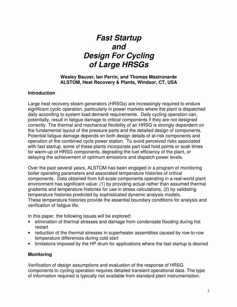
Thermocouples were spot welded directly onto metal surfaces as shown in Figure 2 andcovered with insulation as shown in Figure 3 to ensure accurate metal temperaturereadings.
Tube below fins
Tube to header joint
Header top
Header bottom
Manifold top
Manifold mid-height
Manifold bottom
Lower Superheater Manifold
Lower Superheater Headers (Single-row harps)
Drain
4
Figure 2. Thermocouples on Tube and Header Figure 3. Insulated Thermocouples
Data from metal temperature thermocouples and the plant Distributed Control System(DCS) were integrated and stored on a stand-alone computer. Typical sampling rateswere once per minute to facilitate transient analyses. Monitoring systems have been inoperation at several HRSGs (operating behind GE 7FA gas turbines) for up to threeyears, generating a large database of information on both operating profiles andcomponent responses.
The information obtained from the field monitoring programs has been used to evaluateand confirm mechanical and thermal design assumptions for various components. Inparticular, two areas related to the specific configuration of pressure parts wereexplored in detail. In these two areas the design of ALSTOM HRSGs differs from mostother HRSGs.
1. Superheater and reheater drain system where the drain manifold is separatefrom the lower harp headers. This configuration moves rapid water accumulationaway from the tube entrances into the lower harp header and into a large manifoldlocated below the harp headers, which functions as a generous sluice-way for thereceiving condensate during hot restart. This arrangement precludes the possibilityof water backing up into individual tubes, preventing damage from condensateflooding.
2. The use of small diameter (thin-wall) headers in harps with a single tube row.Small diameter headers in conjunction with step changes in pressure part thicknesslead to minimum tube-to-header temperature differences at the weld joint. The useof a single row eliminates the bend in the tube near the header, and permits morerapid rates of temperature change than more conventional thick-walled headersused with multi-row harps.

5
Temperature histories obtained from the monitoring program have been used to validatethe effectiveness of these two design features in eliminating fatigue damage.
Drain Effectiveness during Hot Restart and GT Purge
The problem of condensate flooding during hot re-start has been reported in theliterature and in various symposia on a number of occasions. This phenomenon takesplace when GT exhaust gas during purge is lower in temperature than the saturationtemperature inside superheater tubes, typical when the boiler is still hot within a fewhours of a GT trip. Under these conditions, a large amount of water will condense in ashort time inside superheater tubes. With conventional multi-row harp construction, thesuperheater header acts as the drain manifold. Backup of condensate into individualtubes can occur when the lower superheater header floods. Such flooding can result indamaging temperature differences between flooded tube and tubes with steam flow,resulting in bowing of tubes or failure of tube-to-header welds.
When the lower superheater headers are segregated from the lower superheatermanifold, as shown in Figure 1, backup of water into individual tubes can not occur.Multiple links between lower superheater headers and the lower manifold assure thatcondensate can drain freely to the lowest point. The following example illustrates theverification of this approach. A full load gas turbine trip occurred at 7:37 AM. The gasturbine was restarted with a purge at 9:14 and reached base load at 10:50. Figure 4shows temperatures on the front high pressure superheater tubes and header over thistime period. See Figure 1 for thermocouple locations.
HPSH1 Harp bottom
500
600
700
800
900
1000
7:30:00 8:42:00 9:54:00 11:06:00
Time
Tem
pera
ture
, deg
. F
Tube Below FinsTube - Header JointHeader Top Header Bottom -
GT Restart
Figure 4. High Pressure Superheater - Tube and Header Temperatures
6
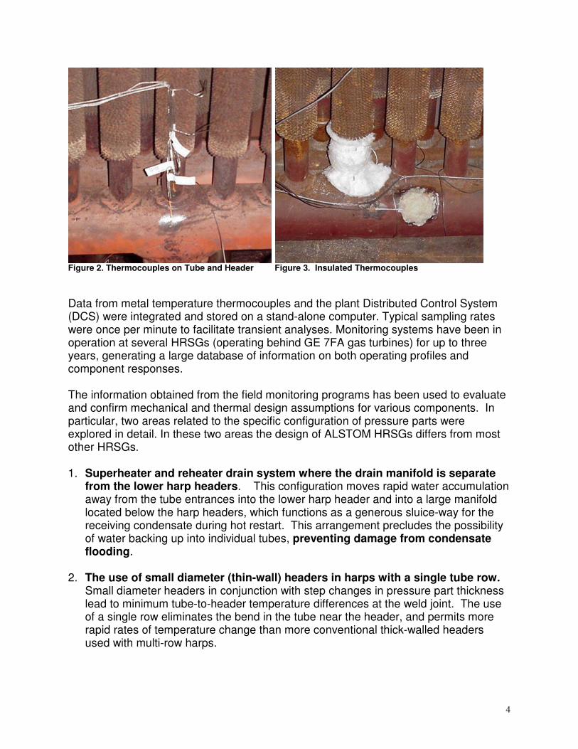
As can be seen, metal temperatures at all locations remain within 28 degrees C (50degrees F) of each other, indicating that the stepped metal thickness and thin headersminimize metal temperature variations and thermal induced stress.
Temperatures around the HP superheater manifold (also see Figure 1) over the sametime period are shown in Figure 5. Temperatures decrease uniformly for about onehour. Then metal temperatures on the bottom of the manifold rapidly decrease fromabout 750oF to 550oF,while temperatures on the top and the sides at mid-heightcontinue to decrease slowly. Bottom temperatures then rapidly rise back to the samerange as the sides and tops. This indicates a rapid build up and draining of water in themanifold. The mid-height temperatures do not follow the temperatures at the bottom.This indicates that the water level never reaches the middle of the manifold. Thegenerous manifold size and the location and size of drain connections on the bottompromote free flow of water to the drain. Measured temperatures confirm the manifoldnever floods, proving effectiveness of the drain system. Temperatures around thecircumference of the entire header decrease at the same time during GT restart. Thisdemonstrates that the header is being uniformly cooled and then heated by steam, withno indication of local cooling by condensate.
HPSH Bottom Manifold
500
600
700
800
900
1000
7:30:00 8:42:00 9:54:00 11:06:00
Time
Tem
pera
ture
deg
. F
top mid height bottom
GT Restart
Figure 5. High Pressure Superheater - Manifold Temperatures
Modeling and Analysis
Analysis of the effects of fast cycling requires both sophisticated stress analysis modelsand realistic thermal boundary conditions. Data obtained from monitoring has been

7
used to provide boundary conditions for existing operating modes. Assessment of otherproposed operating modes and evaluation of components for which monitoring data isnot available requires validated dynamic performance models. Such a model has beendeveloped based on the APROS-5 TM simulation platform. The model includessuperheater sections, reheater sections, HP evaporator sections, applicable controlvalves and associated control systems. Figure 6 shows a schematic of the modeledsystem.
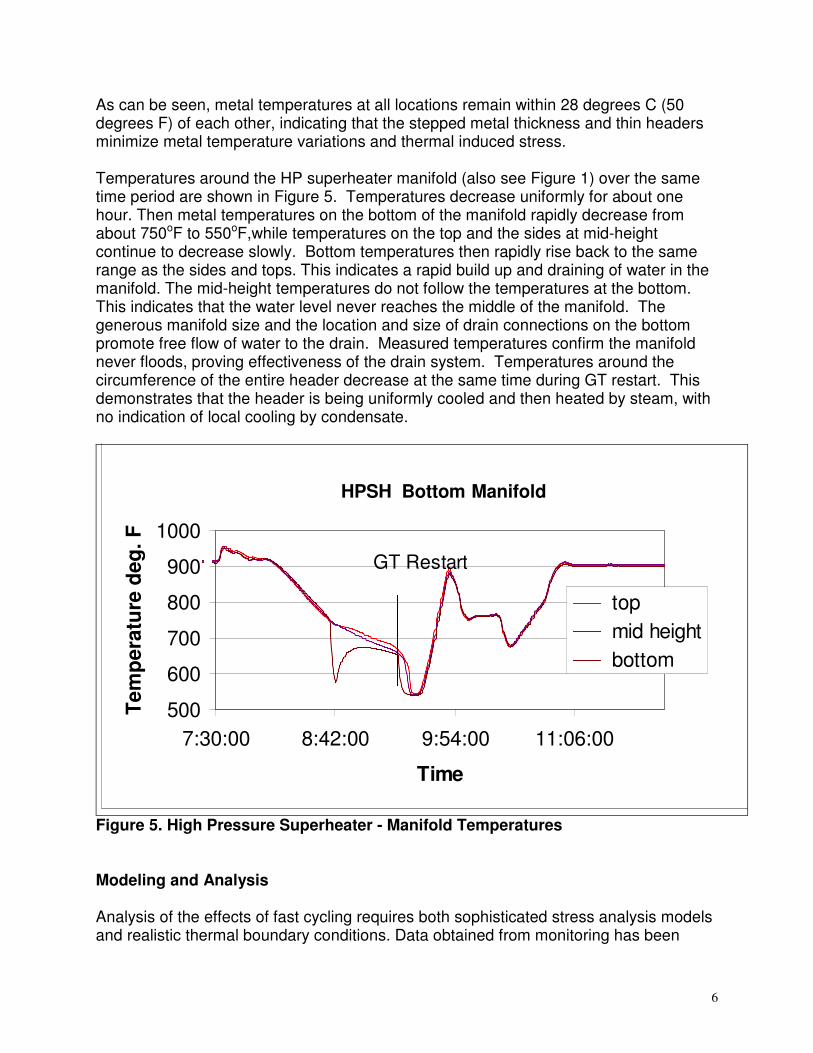
The predicted behavior of several system parameters during the transient is comparedwith the field data in Figures 7 and 8. In the plots, the simulation results are shownusing smooth curves and square or triangular markers are used for field data. In thesimulation, the main steam flow rate increases rapidly and then begins to level off. At50 minutes, the main steam flow again goes through a steep increase as thesuperheater pressure levels off. In the field data, the flow initially shows many sharpincreases and decreases. These may be related to the opening and closings of variousdrains, vents and valves not modeled. In the simulation, the modeled steamtemperature is just at the exit of HPSH1, and, in the absence of significant steam flow,equals the metal temperature. The field data recorded the temperature in the mainsteam piping. The thermal inertia connected to the metal mass of the steam pipe andthe steam headers is not included in the simulation model, yielding a much steeperslope to the temperature rise curve.
After the steam flow starts, the field data rapidly approaches the simulation prediction.Prediction of drum pressure rise up to 17 bar (250 psig) matches field data extremelywell. At this point, the bypass systems begins to control drum pressure and thesimulation uses the ramp rate dictated by the bypass valve set point schedule.

8
Figure 6. Diagram of HRSG Dynamic Model
Model Validation- Cold Start Case- Main steam flow and Temperature -
0
20000
40000
60000
80000
100000
120000
140000
160000
180000
200000
0 10 20 30 40 50 60 70 80 90 100
Time (min)
Ste
am fl
ow (l
b/h)
0
100
200
300
400
500
600
700
800
900
1000
Ste
am T
empe
ratu
re (F
)
MAIN_STM_FLOW (lb/h)
F_HP_STM (lb/h)
STM_TEMP_HPSH1_OUT (F)
T_HP_EAST_OUTL_A (F)
,,,
Figure 7. Main Steam Flow and Temperature Simulation
9
Model Validation- Cold Start Case- HP Drum Pressure -
0
100
200
300
400
500
600
700
800
900
0 10 20 30 40 50 60 70 80 90 100
Time (min)
Pre
ssur
e (p
sia)
HPSH1_PRESSURE (psia)
P_HP_DRUM (psia)
Figure 8. HP Drum Pressure Simulation
With the high quality field data and accurate transient models, detailed stress analysisand life assessment can be performed. This is discussed in the next section.
Analysis and Life Assessment of HRSGs
Analysis and life assessment of HRSGs is becoming increasingly important as the cyclicduty increases and as gas turbines impose greater demands on the HRSG. In thetechnical press, and in various symposia and workshops, the lack of a technicallymature approach to life assessment of HRSGs has been criticized. Most HRSGmanufacturers are only gradually beginning to address design and operational concernsfor cycling service. Many purchasers of new equipment have now become sensitized tothis issue and are now routinely requiring a cyclic life assessment as part of the projectdocumentation.
Life assessment of HRSGs is a complex exercise because the equipment consists oflarge assemblies of interconnected parts with different characteristic dimensions andflexibility, all of which are subjected to complex thermo-mechanical transients. Toadequately represent the functional aspects of HRSG design, while providing sufficientfidelity to compute component lifetimes, requires experience in HRSG design andoperation. It also requires expertise in advanced design and life assessment methodsmore commonly employed for gas turbine components than boilers.

10
The first step in a life assessment study of an HRSG is to determine which of the manycomponents and assemblies actually warrant analysis. This is most easily achieved bya screening methodology to ascertain which components are subjected to the greatestthermal and mechanical loads. This screening must consider the connectivity betweenparts and assemblies that could result in load transfer or temperature differentials notapparent on first inspection. Furthermore, dynamic simulation or field data, such as thatdescribed earlier in this paper, is needed to define the temperature transientsexperienced by components. The screening will identify components and assemblies,such as thick-walled drums or superheater outlet headers, or superheater assemblieswith row-to-row temperature differences. These are then subjected to rigorous analysis,starting with the most severely loaded.
Although ALSTOM has performed numerous analyses of HRSG components, thediscussion that follows focuses on the effect of cold startups on harp assemblies,highlighting some of the differences between single-row and multi-row constructions.This also illustrates the type of analysis that is now being performed to understand thestructural integrity of HRSG components and assemblies. A detailed discussion ofmodeling geometry, derivation of boundary conditions, or numerical details of theanalysis is outside the scope of this paper. The discussion below will emphasize thetechnology employed and focus on the principal conclusions and recommendationsfrom analysis.
Flexibility and Stepped Component Thickness
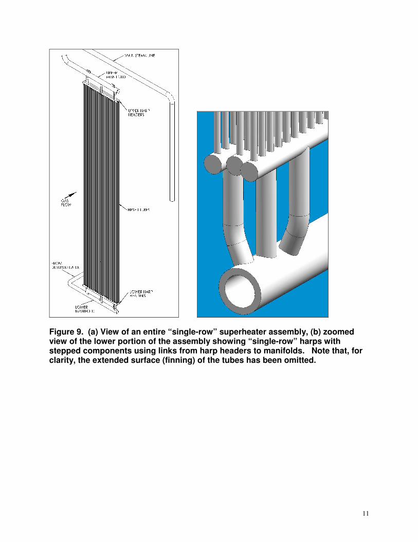
High-pressure superheater assemblies, Figures 9 and 10, are subjected to significantthermal transients due to the rapid rate of rise of gas turbine exhaust gas temperatureon startup, and due to the rapid rate of rise of steam temperature that occurs as steamflow is first established. The superheater assembly, therefore, provides a good exampleof a complex assembly subjected to thermo-mechanical loads, which can be used tohighlight the effect of design and layout of the assembly. For the purpose of analysis,the thermo-mechanical history can be broken into a number of phases to determine thestresses, which can then be appropriately compounded to arrive at a stress range for afatigue life estimate. The key phases of the cold startup are:• Tube row-to-row temperature difference on initial gas turbine firing.• Tube-to-header and header top-to-bottom temperature difference due to differential
heating of tubes and header.• Component-to-component temperature differences due to rapid internal heating as
steam flow is first established.Each of these phases will be examined in the sections that follow.
11
Figure 9. (a) View of an entire “single-row” superheater assembly, (b) zoomedview of the lower portion of the assembly showing “single-row” harps withstepped components using links from harp headers to manifolds. Note that, forclarity, the extended surface (finning) of the tubes has been omitted.

12
Figure 10. (a) View of an entire “multi-row” superheater assembly, and (b)zoomed view showing multiple rows of tubes entering a single header. Note that,for clarity, the extended surface (finning) of the tubes has been omitted.
Two superheater assembly configurations are examined here: (1) “single-row” harpassembly (Figure 9) used by ALSTOM in which each row of tubes enters a singleheader which is linked to a common manifold, and (2) “multi-row” harp assembly (Figure10) in which multiple rows of tubes enter a common header.
For the calculations reported here, the key dimensions of the components of the lowerportion of the assembly are reported in Table 1. This confirms that the superheatertubes are the same and that the manifold in the single-row harp assembly has similardimensions to the header in the multi-row harp assembly.

13
Table 1. Comparison of component sizes for harp assembly analyses.Component Tube Lower Header
Single-row HarpLower ManifoldSingle-row Harp
Lower HeaderMulti-row Harp
Outer diameter 38 mm (1.5”) 114 mm (4.5”) 273 mm (10.75”) 273 mm (10.75”)
Wall thickness 5.2 mm (.205”) 17 mm (.67”) 35 mm (1.3”) 35 mm (1.3”)
Ratio of header wallthickness to branchattachment
3.3 2.1 6.7
Tube Row-to-Row Temperature Differences during Cold Start
The effects of a tube row-to-row temperature difference are evaluated first. The row-to-row temperature difference is most severe on a cold start when the superheater tubesare initially cool (near ambient temperature) and are then subject to warm exhaust gaswhich rapidly reaches 370C (700F). A row-to-row temperature difference is establishedas the first tube row extracts heat from the exhaust gas such that a little less heatreaches the second row, etc. The row-to-row temperature difference depends on theexhaust gas mass flow, temperature, and tube-fin configuration, and the loadingcharacteristic of the gas turbine. Typical values are:
Conventional Startup: typical range 20C to 30C (36F to 54F)
Fast Startup: typical range 30C to 50C (54F to 90F)
In the discussion below, a temperature difference of 25C (45F) has been assumed. Foran accurate analysis of the deformation and stress in the single-row and multi-rowsuperheater harp assemblies, finite element models have been carefully designed tocapture the global geometry, thereby giving a good representation of the overallflexibility of the assembly, while also modeling local stress concentrating features. Thisavoids the use of, often ill-defined, stress concentration factors from tables tocompensate for the local features that are not represented by beam or shell elements.The tubes, header and manifolds are all constructed from grade 91 steel (9Cr-1Mo-V-Nb) and material properties have been assigned accordingly.
The results of the analyses highlight a number of design features. Firstly, in the presentanalysis the peak stresses in the single-row and multi-row harp assemblies are quitesimilar and do not exceed the yield stress of the grade 91 material, therefore themoderate 25C (45F) row-to-row temperature difference alone will not cause fatiguefailure of either assembly. However, it is evident from Figure 11 that the highest stressin the multi-row harp assembly is concentrated in the tube (a thin walled component) atthe toe of the weld. There are many of these locations on the harp assembly and,therefore, for a larger temperature difference many potential failure sites that are

14
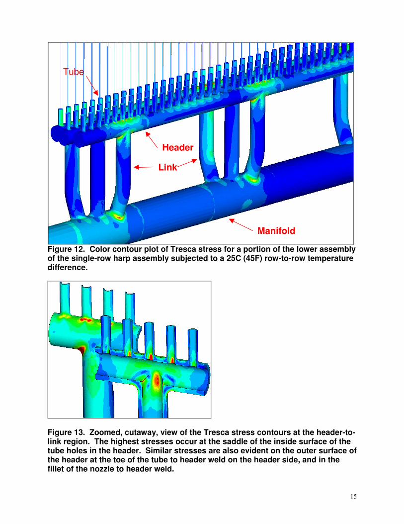
generally difficult to access for inspection and repair. For the single-row harp assembly,Figures 12 and 13 illustrate that the stepped component thickness distributes the stressbetween the harp header and link to manifold connection. The highest stresses aretherefore in relatively heavy wall components (links and harp headers). The link-to-manifold and link-to-header connections can be inspected with relative ease.
Figure 11. Color contour plot of Tresca stress for a portion of the lower assemblyof the multi-row harp assembly subjected to a 25C (45F) row-to-row temperaturedifference.
15
Figure 12. Color contour plot of Tresca stress for a portion of the lower assemblyof the single-row harp assembly subjected to a 25C (45F) row-to-row temperaturedifference.
Figure 13. Zoomed, cutaway, view of the Tresca stress contours at the header-to-link region. The highest stresses occur at the saddle of the inside surface of thetube holes in the header. Similar stresses are also evident on the outer surface ofthe header at the toe of the tube to header weld on the header side, and in thefillet of the nozzle to header weld.
Header
Manifold
Link
Tube

16
Analyses of other attached piping arrangements demonstrate that the magnitudes of thestresses do depend on the stiffness of the attached piping, which reacts to the globalmotion of the harp assembly. A bounding case is that of rigid piping (no rotation of thelower header or manifold) which shows that the stresses in the multi-row assembly canbe significantly higher (by 25%) than those in the single-row assembly. Even such amodest stress increase can halve the fatigue life of a component, which further servesto highlight the value of this type of analysis and the need to consider the relevantfactors during pressure part design and layout.
Differential Heating by Exhaust Gas
During the initial period of gas turbine firing and loading, as the tube row-to-rowtemperature difference is established, additional temperature differentials are set upbetween the tube and the header and between the top and bottom of the header. Thethin-walled finned tubes warm more rapidly than the header, which causes a tube-to-header temperature difference. This difference is more pronounced for the multi-rowassembly because the tubes enter a thicker header which takes longer to warm, therebycompounding the stress due to the tube row-to-row temperature difference. In the caseof the single-row assembly, the temperature difference between the tube and theheader is less significant because of the smaller difference in wall thickness betweenthe tube and the header.
A temperature difference also develops between the top and bottom of the headers,both for the single-row and multi-row assemblies, because the top of the header iswarmed by the combined effect of exhaust gas and conduction from the tubes. Theresulting temperature difference between the top and bottom of the header is muchmore significant for the multi-row harp assembly because the header has a much largerdiameter and is thicker, thereby prolonging the time for circumferential heat conduction.The single-row construction places the larger diameter, thick-walled, manifold out of theexhaust gas flow and therefore only the smaller diameter, thinner-walled, harp headersare subjected to this differential heating. Field data confirm that conduction within thesmall diameter, thin walled, header is sufficient to ensure that the top-to-bottomtemperature difference on the header is no more than a few degrees.
Temperature Differences of Branch Connections
The final phase of the significant thermal transients on a cold startup is the rapid rate ofrise of steam temperature that occurs as steam flow is first established. Generally, thisdoes not occur until sufficient heat has been absorbed in the evaporator by which timethe temperature differences described earlier have died away. Therefore, the rapidlyrising temperature of the steam heats components of differing wall thickness at differingrates, which, in turn, creates local thermal stresses at connections between

17
components. The rates of temperature rise can be quite large 70C/min (125F/min) andheat transfer coefficients are also large because the cool components (especiallyheaders and manifolds out of the exhaust gas flow) are warmed by condensationheating.
It is relatively straightforward to compute the temperature difference that can beestablished between components by first performing a transient heat transfer analysisand then evaluating the mean through-wall temperature for each component. Thismean through-wall temperature can then be compared for connected components toprovide an estimate of the typical temperature difference between the components.These computations have been performed for the single-row and multi-row harpassemblies discussed earlier, the dimensions of which are given in Table 1. Ofparticular note is the ratio of header wall thickness to branch connection thickness,which is two to three times greater for the multi-row harp.
The results for the components of the multi-row assembly are shown in Figure 14,which presents the mean through-wall temperature of tube and header as a function oftime and also plots the temperature difference between these components. Thetemperature difference between the tube and header reaches a peak value of 103C(185F).
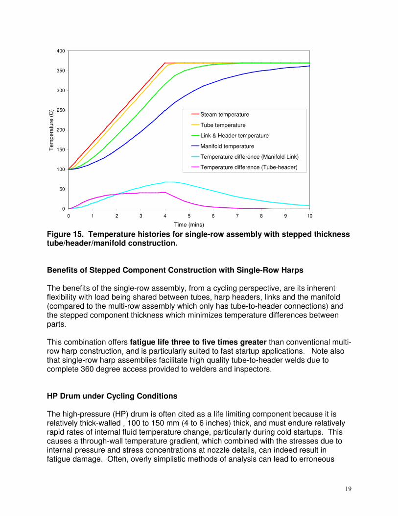
The results for the components of the single-row assembly are shown in Figure 15,which presents the mean though-wall temperature of the tube, header/link and manifoldas a function of time and also plots the tube-to-header and link-to-manifold temperaturedifference. The tube-to-header temperature difference reaches a modest 41C (74F)and the link-to-manifold temperature difference reaches a value of 68C (122F).
Although the tubes and manifolds are of similar thickness in the two cases, the single-row assembly adds the links and harp headers (which are of equal thickness and,therefore, do not have any temperature difference). The stepped componentthickness of the single-row construction therefore reduces the temperature differencebetween parts which ensures that components subject to high stresses during the row-to-row temperature difference are not also subject to high stresses as steam flow is firstestablished. This is critical for highly cycled units.
Combination of Row-to-Row and Thermal Differences at Branch Connections
Combining the stresses from the three phases of the startup transient shows that acontinual compounding of stress occurs at the tube-to-header connection of the multi-row assembly. The single-row assembly, however, minimizes temperature differentialsand hence thermal stresses, such that the temperature difference between parts issignificantly lower (e.g. reduced from 103C (185F) for the multi-row assembly to 41C(74F) for the single-row assembly, at the tube-to-header connection). Therefore,although detailed analysis of the single-row and multi-row assemblies subjected to row-to-row temperature differences showed that the peak stresses were of similar

18
magnitude, it is apparent that the complete thermal cycle should be considered in afatigue life evaluation. The flexibility and stepped thickness of the single-row assemblyavoids compounding of temperature difference and stress from the various phases ofthe startup transient in the same geometric location.
0
50
100
150
200
250
300
350
400
0 1 2 3 4 5 6 7 8 9 10
Time (mins)
Tem
pera
ture
(C
)
Steam temperature
Tube temperature
Manifold temperature
Temperature difference (Tube-Manifold)
Figure 14. Temperature histories for thick-walled header in a multi-row assembly.
19
0
50
100
150
200
250
300
350
400
0 1 2 3 4 5 6 7 8 9 10
Time (mins)
Tem
pera
ture
(C)
Steam temperature
Tube temperature
Link & Header temperature
Manifold temperature
Temperature difference (Manifold-Link)
Temperature difference (Tube-header)
Figure 15. Temperature histories for single-row assembly with stepped thicknesstube/header/manifold construction.
Benefits of Stepped Component Construction with Single-Row Harps
The benefits of the single-row assembly, from a cycling perspective, are its inherentflexibility with load being shared between tubes, harp headers, links and the manifold(compared to the multi-row assembly which only has tube-to-header connections) andthe stepped component thickness which minimizes temperature differences betweenparts.
This combination offers fatigue life three to five times greater than conventional multi-row harp construction, and is particularly suited to fast startup applications. Note alsothat single-row harp assemblies facilitate high quality tube-to-header welds due tocomplete 360 degree access provided to welders and inspectors.
HP Drum under Cycling Conditions
The high-pressure (HP) drum is often cited as a life limiting component because it isrelatively thick-walled , 100 to 150 mm (4 to 6 inches) thick, and must endure relativelyrapid rates of internal fluid temperature change, particularly during cold startups. Thiscauses a through-wall temperature gradient, which combined with the stresses due tointernal pressure and stress concentrations at nozzle details, can indeed result infatigue damage. Often, overly simplistic methods of analysis can lead to erroneous

20
results – either giving a false sense of security or undue pessimism. The reasons arethat methods such as EN12952 are often used which are generally highly conservativefor the basic effect of the through-wall temperature difference due to the internaltemperature change but neglect the assembly loads such as reactions and moments atdowncomers and risers. The limitations of these analysis methods can be overcomewith appropriate dynamic models to simulate the actual rate of temperature rise in theHP drum while also giving information on the temperature differentials between thedrum, downcomers and evaporator tubes which give rise to assembly stresses.
Although a detailed analysis of this topic is beyond the scope of this paper,dynamic modeling at ALSTOM has shown that the initial rates of rise of temperature inthe drum-evaporator system are primarily controlled by the heat input from the gasturbine and are not affected by steam bypass operation. As a result, the HRSG drummust meet the transient heating imposed by the gas turbine, or the gas turbine exhaustgas transient must be modified to meet the needs of the HRSG.
It can demonstrated that an HP Drum with a thickness of less than 140 mm (5.5”) willtypically be suitable for cycling service with today’s gas turbine startup practices.With fast loading of the gas turbine, however, the HP drum becomes a limitingcomponent for fatigue life in cycling service. It is expected that fast loading of gasturbines will be become more prevalent in the future as plant owners strive to reducethe time to achieve emissions compliance and to reduce startup fuel consumption.For this type of plant, elimination of the HP steam drum by using a once-throughevaporator system will provide the thermal flexibility to withstand daily cycling for thethirty-year life of the plant.
Conclusion
Horizontal HRSGs have become the technology of choice and the dominantconfiguration world-wide for large HRSGs in the past ten years. To truly addresscustomer’s demands for operational flexibility through dispatch and cycling of combinedcycle plants, key features in the design of HRSGs can greatly enhance the fatiguetolerance of certain components.
Adopting pressure part features such as single-row harp, stepped component thickness,and enhanced drain systems will improve the thermal response of large HRSGs andeliminate the need for hold points specifically to accommodate the HRSG during theconservative gas turbine loading ramps that are in use today in many plants. In thefuture, as fast loading of large gas turbines becomes economically advantageous,single row harps, coupled with stepped component construction, will accommodatetemperature transients that would otherwise damage and limit the life of an HRSG builtwith multi-row harps.