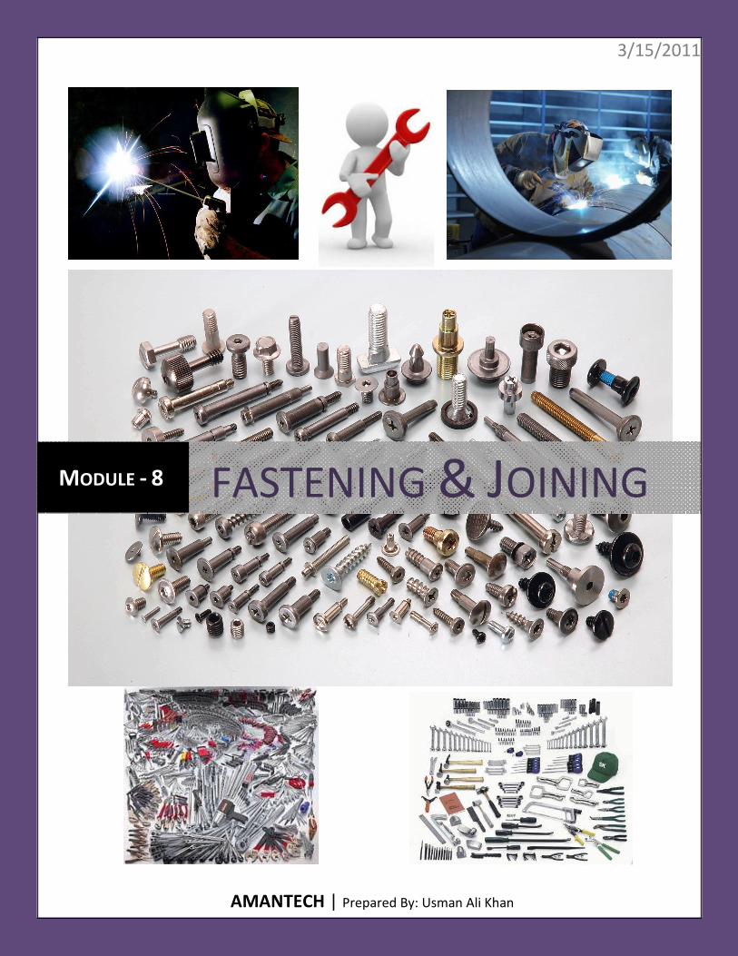
fastening & joining
TRANSCRIPT
3/15/2011
AMANTECH | Prepared By: Usman Ali Khan
MODULE - 8 FASTENING & JOINING
~ 2 ~
Table of Contents
8.1 - IDENTIFY TYPES AND APPLICATIONS OF MECHANICAL FASTENING DEVICES. ........................................... 7
8.1.1 - FASTENING ................................................................................................................................................................. 7
8.1.2 - NUTS .......................................................................................................................................................................... 7
8.1.3 - BOLTS ....................................................................................................................................................................... 14
8.1.4 - SCREW ...................................................................................................................................................................... 17
8.1.5 - WASHER ................................................................................................................................................................... 19
8.1.6 - RIVET ........................................................................................................................................................................ 23
8.1.7 - COUNTER SUNK........................................................................................................................................................ 28
8.2 - IDENTIFY TYPES AND APPLICATIONS OF SCREW THREADS .................................................................... 31
8.2.1 - SCREW THREAD ........................................................................................................................................................ 31
8.2.2 - TYPES OF SCREW THREADS ...................................................................................................................................... 32
ISO METRIC SCREW THREADS ......................................................................................................................................... 32
BRITISH STANDARD SCREW THREADS ............................................................................................................................ 34
BA SCREW THREADS........................................................................................................................................................ 35
UNIFIED THREADS STANDARD ........................................................................................................................................ 36
ACME SCREW THREADS .................................................................................................................................................. 38
BUTTRESS SCREW THREADS ............................................................................................................................................ 38
SQUARE SCREW THREADS .............................................................................................................................................. 39
8.3 - IDENTIFY TYPES AND APPLICATIONS OF SPANNERS .............................................................................. 41
8.4 - IDENTIFY RIVETED AND BOLT JOINTS .................................................................................................... 45
8.4.1 - JOINTS ...................................................................................................................................................................... 45
8.4.2 - BUTT JOINT .............................................................................................................................................................. 46
8.4.3 - LAP JOINT ................................................................................................................................................................. 46
8.5 - IDENTIFY DEFECTS IN RIVETED AND BOLT JOINTS ................................................................................. 48
8.5.1 - DEFECTS IN BOLTED JOINT ....................................................................................................................................... 48
8.5.2 - DEFECTS IN RIVETED JOINT ...................................................................................................................................... 49
8.6 - IDENTIFY SELF SECURED SHEET METAL JOINTS AND STATE APPLICATIONS ............................................ 52
8.6.1 – APPLICATIONS ......................................................................................................................................................... 52
8.6.2 - SELF SECURED JOINTS .............................................................................................................................................. 52
THE GROOVED SEAM ...................................................................................................................................................... 53
THE INTERNAL GROOVED SEAM ..................................................................................................................................... 53
THE DOUBLE GROOVED SEAM ........................................................................................................................................ 53
~ 3 ~
8.6.3 - ALLOWANCES FOR SELF-SECURED JOINTS ............................................................................................................... 54
GROOVED SEAM.............................................................................................................................................................. 54
DOUBLE GROOVED SEAM ............................................................................................................................................... 54
PANED DOWN SEAM ....................................................................................................................................................... 54
KNOCKED UP SEAM ......................................................................................................................................................... 54
8.6.4 - PITTSBURGH LOCKS SEAM ....................................................................................................................................... 54
8.7 - IDENTIFY THE EQUIPMENT AND CONSUMABLES USED FOR SOFT SOLDERING ....................................... 56
8.7.1 - SOLDERING ............................................................................................................................................................... 56
8.7.2 - EQUIPMENT ............................................................................................................................................................. 56
SOLDERING IRONS:.......................................................................................................................................................... 56
SOURCES OF HEAT .......................................................................................................................................................... 57
SOLDERING COPPERS ...................................................................................................................................................... 57
8.7.3 - FILING AND TINNING COPPERS ................................................................................................................................ 58
8.7.4 - FORGING SOLDERING COPPERS ............................................................................................................................... 59
8.7.5 - ELECTRIC SOLDERING COPPERS ............................................................................................................................... 60
8.7.6 - GAS TORCHES ........................................................................................................................................................... 60
8.7.7 - SOFT SOLDER............................................................................................................................................................ 61
TIN-LEAD SOLDER ............................................................................................................................................................ 61
TIN-ANTIMONY-LEAD SOLDER ........................................................................................................................................ 61
TIN-ZINC SOLDER ............................................................................................................................................................. 61
LEAD-SILVER SOLDER ...................................................................................................................................................... 61
TIN-ANTIMONY SOLDER .................................................................................................................................................. 61
TIN-SILVER SOLDER ......................................................................................................................................................... 61
8.7.8 - FLUXES ..................................................................................................................................................................... 62
NONCORROSIVE FLUXES ................................................................................................................................................. 63
CORROSIVE FLUXES ......................................................................................................................................................... 63
8.8 – BASIC PRINCIPLES OF SOFT SOLDERING ............................................................................................... 64
8.8.1 - HEAT AND TIME ....................................................................................................................................................... 64
8.8.2 - WETTING .................................................................................................................................................................. 64
8.8.3 - SOLDER FLOW .......................................................................................................................................................... 64
8.8.4 - SURFACE CONDITION ............................................................................................................................................... 65
8.8.5 - THERMAL MASS ....................................................................................................................................................... 65
8.8.6 - TOOLS ....................................................................................................................................................................... 65
8.8.7 - SOLDERING TECHNIQUES ......................................................................................................................................... 65
8.9 - IDENTIFY THE EQUIPMENT AND CONSUMABLES USED FOR BRAZING .................................................... 66
~ 4 ~
8.9.1 - BRAZING ................................................................................................................................................................... 66
ADVANTAGES AND DISADVANTAGES ............................................................................................................................. 66
8.9.2 - FILLER METALS ......................................................................................................................................................... 67
8.9.3 - ROLE OF ELEMENTS ................................................................................................................................................. 68
8.9.4 - DEOXIDIZERS ............................................................................................................................................................ 71
8.9.5 - ACTIVE METALS ........................................................................................................................................................ 71
8.9.6 - IMPURITIES .............................................................................................................................................................. 71
8.9.7 - MELTING BEHAVIOR ................................................................................................................................................ 72
8.9.8 - INTERACTION WITH BASE METALS .......................................................................................................................... 72
8.10 - EXPLAIN THE BASIC PRINCIPLES OF BRAZING ...................................................................................... 74
8.10.1 - BRAZING ................................................................................................................................................................. 74
8.10.2 - FUNDAMENTALS .................................................................................................................................................... 74
8.10.3 - FLUX ....................................................................................................................................................................... 75
8.10.4 - FILLER MATERIALS .................................................................................................................................................. 76
8.10.5 - TORCH BRAZING..................................................................................................................................................... 76
8.10.6 - FURNACE BRAZING ................................................................................................................................................ 77
8.10.7 - SILVER BRAZING ..................................................................................................................................................... 78
8.10.8 - BRAZE WELDING .................................................................................................................................................... 79
8.10.9 - CAST IRON "WELDING" .......................................................................................................................................... 79
8.10.10 - VACUUM BRAZING ............................................................................................................................................... 79
8.10.11 - DIP BRAZING ........................................................................................................................................................ 80
8.10.12 - HEATING METHODS ............................................................................................................................................. 80
8.11 - IDENTIFY THE EQUIPMENT AND CONSUMABLES USE FOR OXY-FUEL GAS WELDING ............................ 81
8.11.1 - EQUIPMENT AND CONSUMABLES USE FOR OXY-FUEL GAS WELDING ................................................................. 81
8.11.2 - CYLINDER ............................................................................................................................................................... 82
8.11.3 - TORCH .................................................................................................................................................................... 84
8.11.4 - REGULATOR ........................................................................................................................................................... 85
8.11.5 - HOSE ...................................................................................................................................................................... 85
8.11.6 - FILLER WIRE............................................................................................................................................................ 86
8.12 - EXPLAIN THE BASIC PRINCIPLES OF OXY-FUEL GAS WELDING .............................................................. 87
8.12.1 - OXY-FUEL WELDING ............................................................................................................................................... 87
8.12.2 - GAS WELDING PROCESS AND GASES ..................................................................................................................... 88
8.12.3 - APPLICATION .......................................................................................................................................................... 89
8.13 - IDENTIFY FLAME SETTING, OXIDIZING, CARBURIZING, AND NEUTRAL ................................................. 95
8.13.1 - FLAME .................................................................................................................................................................... 95
~ 5 ~
8.13.2 - CREATING A FLAME................................................................................................................................................ 96
NEUTRAL FLAME ............................................................................................................................................................. 97
CARBONIZING FLAME...................................................................................................................................................... 97
OXIDIZING FLAME ........................................................................................................................................................... 98
8.14 - IDENTIFY THE EQUIPMENT AND CONSUMABLES USED FOR MANUAL METAL ARC WELDING ............... 99
8.14.1 - OVERVIEW .............................................................................................................................................................. 99
8.14.2 - EQUIPMENTS & CONSUMABLES ............................................................................................................................ 99
WELDING POWER SUPPLY............................................................................................................................................... 99
TRANSFORMER .............................................................................................................................................................. 100
GENERATOR & ALTERNATOR ........................................................................................................................................ 100
INVERTER....................................................................................................................................................................... 100
ELECTRODE HOLDER ..................................................................................................................................................... 100
GROUND CLAMP ........................................................................................................................................................... 100
CABLES .......................................................................................................................................................................... 101
ELECTRODES .................................................................................................................................................................. 101
FLUX .............................................................................................................................................................................. 101
8.15 - EXPLAIN THE BASIC PRINCIPLES OF MANUAL METAL ARC WELDING.................................................. 102
8.15.1 - SHIELDED METAL ARC WELDING ......................................................................................................................... 102
8.15.2 - DEVELOPMENT..................................................................................................................................................... 102
8.15.3 - OPERATION .......................................................................................................................................................... 103
SMAW WELD AREA ....................................................................................................................................................... 103
WELDING JOINT TYPES .................................................................................................................................................. 104
EQUIPMENT .................................................................................................................................................................. 107
QUALITY ........................................................................................................................................................................ 107
SAFETY ........................................................................................................................................................................... 108
APPLICATION AND MATERIALS ..................................................................................................................................... 109
8.16 - IDENTIFY MANUAL OXY-FUEL GAS CUTTING EQUIPMENT ................................................................. 111
8.16.1 - OXY-ACETYLENE CUTTING.................................................................................................................................... 111
8.16.2 - SAFETY .................................................................................................................................................................. 113
8.16.3 - EQUIPMENT ......................................................................................................................................................... 114
OXYGEN CYLINDER ........................................................................................................................................................ 116
OXYGEN CYLINDER VALVE ............................................................................................................................................. 116
ACETYLENE CYLINDER ................................................................................................................................................... 117
ACETYLENE CYLINDER VALVE ........................................................................................................................................ 117
PRESSURE REGULATORS ............................................................................................................................................... 118

~ 6 ~
HOSES & CONNECTIONS ............................................................................................................................................... 118
OXY-FUEL TORCH .......................................................................................................................................................... 118
CHECK VALVES & FLASHBACK ARRESTORS ................................................................................................................... 119
8.17 - IDENTIFY GASES USED FOR MANUAL OXY-FUEL GAS CUTTING .......................................................... 120
8.17.1 - OXYGEN ................................................................................................................................................................ 120
8.17.2 - ACETYLENE ........................................................................................................................................................... 120
8.17.3 - STORAGE .............................................................................................................................................................. 121
~ 7 ~
Fastening & Joining Module
No. 8.01
Prepared
by Abdul Basit
Course Certificate in Engineering Skills Duration 60 - Mins
Teaching Aid
Topic Identify types and applications of mechanical fastening devices
8.1 - IDENTIFY TYPES AND APPLICATIONS OF MECHANICAL FASTENING DEVICES.
8.1.1 - FASTENING
A fastener is a hardware device that mechanically joins or affixes two or more objects together. Fasteners can also be
used to close a container such as a bag, a box, or an envelope; or they may involve keeping together the sides of an
opening of flexible material, attaching a lid to a container. There are various types of hardware are mentioned below:
Nuts
Bolts/Screws
Studs
Washers
Rivets
Cotter Pin
Split Pin
Gaskets
8.1.2 - NUTS
A nut is a type of hardware fastener with a threaded hole. Nuts are almost always used opposite a mating bolt to
fasten a stack of parts together.
TYPES OF NUTS
Acron (Cap nut)
Clip on Nut (j-nut or U nut)
Coupling Nut
Cross dowel nut
Flange Nut
Hex Nut
Insert Nut
Internal Wrenching Nut
Knurled Nut
Lock Nut
Lug Nut
PEM Nut,
Plate Nut
Rivet Nut
Slotted Nut
~ 8 ~
Square Nut
Self Lock Nut
Self Aligning Nut
Split Nut
Swage Nut
T-Nut
T-slot Nut (T-groove nut)
Weld Nut
Welded Nut
Well Nut
Wing Nut
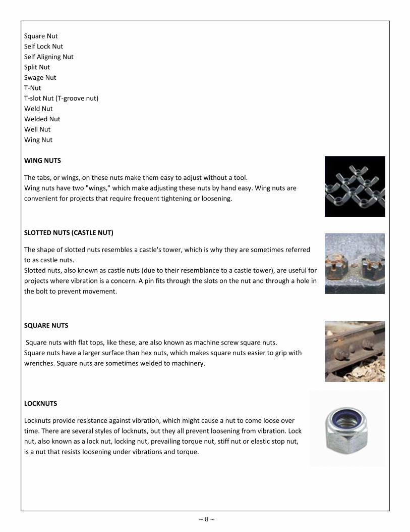
WING NUTS
The tabs, or wings, on these nuts make them easy to adjust without a tool.
Wing nuts have two "wings," which make adjusting these nuts by hand easy. Wing nuts are
convenient for projects that require frequent tightening or loosening.
SLOTTED NUTS (CASTLE NUT)
The shape of slotted nuts resembles a castle's tower, which is why they are sometimes referred
to as castle nuts.
Slotted nuts, also known as castle nuts (due to their resemblance to a castle tower), are useful for
projects where vibration is a concern. A pin fits through the slots on the nut and through a hole in
the bolt to prevent movement.
SQUARE NUTS
Square nuts with flat tops, like these, are also known as machine screw square nuts.
Square nuts have a larger surface than hex nuts, which makes square nuts easier to grip with
wrenches. Square nuts are sometimes welded to machinery.
LOCKNUTS
Locknuts provide resistance against vibration, which might cause a nut to come loose over
time. There are several styles of locknuts, but they all prevent loosening from vibration. Lock
nut, also known as a lock nut, locking nut, prevailing torque nut, stiff nut or elastic stop nut,
is a nut that resists loosening under vibrations and torque.
~ 9 ~
TYPES OF LOCK NUT
Castle Nut,
Distorted thread locknut
Centre lock nut
Elliptical offset locknut
Top lock nut
Interfering thread nut
Tapered thread nut
Jam Nut
Jet Nut (K-nut)
Keps Nut (K nut, washer nut)
Nylock Plate Nut
Nylock (Polymer insert nut)
Serrated Face Nut
Serrated Flange Nut
Speed Nut (sheet metal nut, Tinnerman nut)
Split Beam Nut
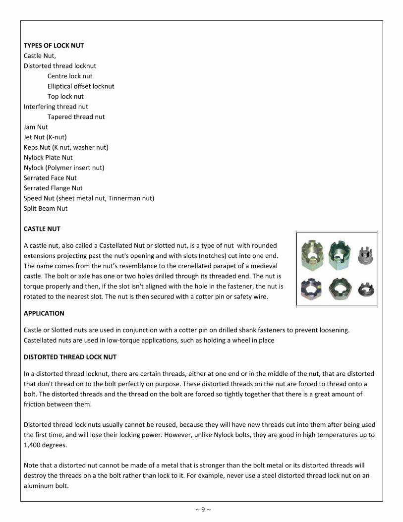
CASTLE NUT
A castle nut, also called a Castellated Nut or slotted nut, is a type of nut with rounded
extensions projecting past the nut's opening and with slots (notches) cut into one end.
The name comes from the nut’s resemblance to the crenellated parapet of a medieval
castle. The bolt or axle has one or two holes drilled through its threaded end. The nut is
torque properly and then, if the slot isn't aligned with the hole in the fastener, the nut is
rotated to the nearest slot. The nut is then secured with a cotter pin or safety wire.
APPLICATION
Castle or Slotted nuts are used in conjunction with a cotter pin on drilled shank fasteners to prevent loosening.
Castellated nuts are used in low-torque applications, such as holding a wheel in place
DISTORTED THREAD LOCK NUT
In a distorted thread locknut, there are certain threads, either at one end or in the middle of the nut, that are distorted
that don't thread on to the bolt perfectly on purpose. These distorted threads on the nut are forced to thread onto a
bolt. The distorted threads and the thread on the bolt are forced so tightly together that there is a great amount of
friction between them.
Distorted thread lock nuts usually cannot be reused, because they will have new threads cut into them after being used
the first time, and will lose their locking power. However, unlike Nylock bolts, they are good in high temperatures up to
1,400 degrees.
Note that a distorted nut cannot be made of a metal that is stronger than the bolt metal or its distorted threads will
destroy the threads on a the bolt rather than lock to it. For example, never use a steel distorted thread lock nut on an
aluminum bolt.
~ 10 ~
APPLICATION
A distorted thread lock nut is a type of locknut that uses a deformed section of thread to keep the nut from loosening
from vibrations or rotation of the clamped item. They are broken down into three types: elliptical offset nuts, center
lock nuts, and top lock nuts.
TYPES OF DISTORTED THREAD LOCK NUT
Center lock nut: Center lock nuts are similar to elliptical offset nuts, except that they are distorted in the middle of the
nut. This allows the nut to be started from either side.
ELLIPTICAL OFFSET LOCKNUT
Elliptical offset nuts, also known as oval locknuts or non-slotted hex locknuts, is a nut that has been deformed at one
end so that the threads no longer perfectly circular. The deformed end is usually shaped into an ellipse. The nut is easily
started on the male fastener as the bottom portion is not deformed. As the male fastener reaches the deformed
section it deforms the threads of the nut elastically back into a circle. This action increases the friction between the nut
and the fastener greatly and creates the locking action. Due to the elastic nature of the deformation the nuts can be
reused indefinitely.
Top lock nut: Top lock nuts are also similar to elliptical offset nuts, except that the whole thread on one end is not
distorted. Instead only three small sections of the thread are deformed on one end.
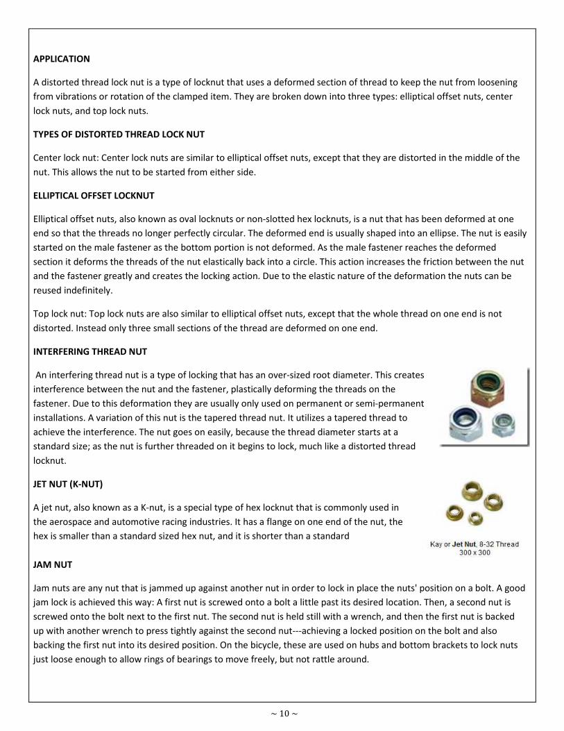
INTERFERING THREAD NUT
An interfering thread nut is a type of locking that has an over-sized root diameter. This creates
interference between the nut and the fastener, plastically deforming the threads on the
fastener. Due to this deformation they are usually only used on permanent or semi-permanent
installations. A variation of this nut is the tapered thread nut. It utilizes a tapered thread to
achieve the interference. The nut goes on easily, because the thread diameter starts at a
standard size; as the nut is further threaded on it begins to lock, much like a distorted thread
locknut.
JET NUT (K-NUT)
A jet nut, also known as a K-nut, is a special type of hex locknut that is commonly used in
the aerospace and automotive racing industries. It has a flange on one end of the nut, the
hex is smaller than a standard sized hex nut, and it is shorter than a standard
JAM NUT
Jam nuts are any nut that is jammed up against another nut in order to lock in place the nuts' position on a bolt. A good
jam lock is achieved this way: A first nut is screwed onto a bolt a little past its desired location. Then, a second nut is
screwed onto the bolt next to the first nut. The second nut is held still with a wrench, and then the first nut is backed
up with another wrench to press tightly against the second nut---achieving a locked position on the bolt and also
backing the first nut into its desired position. On the bicycle, these are used on hubs and bottom brackets to lock nuts
just loose enough to allow rings of bearings to move freely, but not rattle around.
~ 11 ~
APPLICATION
Jam nuts are used when the nuts need to be locked into place along a bolt without being pressed against another
surface---they press on one another, instead. Jam nuts do not provide an unbreakable lock, but they are sufficient,
sometimes necessary, and they are reusable.
KEPS NUT (K-NUT OR WASHER NUT)
A Keps nut, also called a K-nut or washer nut, is a nut with an attached, free-spinning washer. It is used to make
assembly more convenient. Common washer types are star-type lock washers, conical, and flat washers.
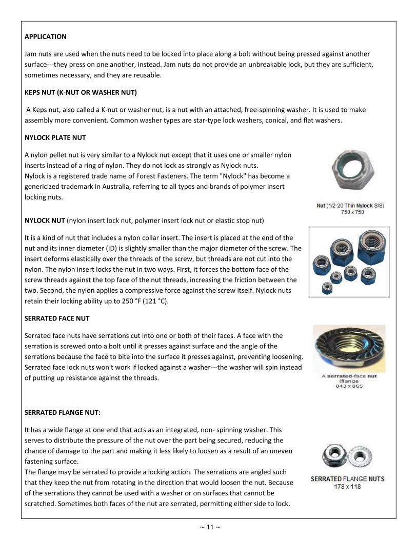
NYLOCK PLATE NUT
A nylon pellet nut is very similar to a Nylock nut except that it uses one or smaller nylon
inserts instead of a ring of nylon. They do not lock as strongly as Nylock nuts.
Nylock is a registered trade name of Forest Fasteners. The term "Nylock" has become a
genericized trademark in Australia, referring to all types and brands of polymer insert
locking nuts.
NYLOCK NUT (nylon insert lock nut, polymer insert lock nut or elastic stop nut)
It is a kind of nut that includes a nylon collar insert. The insert is placed at the end of the
nut and its inner diameter (ID) is slightly smaller than the major diameter of the screw. The
insert deforms elastically over the threads of the screw, but threads are not cut into the
nylon. The nylon insert locks the nut in two ways. First, it forces the bottom face of the
screw threads against the top face of the nut threads, increasing the friction between the
two. Second, the nylon applies a compressive force against the screw itself. Nylock nuts
retain their locking ability up to 250 °F (121 °C).
SERRATED FACE NUT
Serrated face nuts have serrations cut into one or both of their faces. A face with the
serration is screwed onto a bolt until it presses against surface and the angle of the
serrations because the face to bite into the surface it presses against, preventing loosening.
Serrated face lock nuts won't work if locked against a washer---the washer will spin instead
of putting up resistance against the threads.
SERRATED FLANGE NUT:
It has a wide flange at one end that acts as an integrated, non- spinning washer. This
serves to distribute the pressure of the nut over the part being secured, reducing the
chance of damage to the part and making it less likely to loosen as a result of an uneven
fastening surface.
The flange may be serrated to provide a locking action. The serrations are angled such
that they keep the nut from rotating in the direction that would loosen the nut. Because
of the serrations they cannot be used with a washer or on surfaces that cannot be
scratched. Sometimes both faces of the nut are serrated, permitting either side to lock.
~ 12 ~
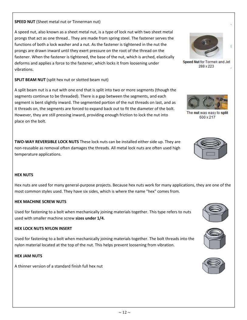
SPEED NUT (Sheet metal nut or Tinnerman nut)
A speed nut, also known as a sheet metal nut, is a type of lock nut with two sheet metal
prongs that act as one thread.. They are made from spring steel. The fastener serves the
functions of both a lock washer and a nut. As the fastener is tightened in the nut the
prongs are drawn inward until they exert pressure on the root of the thread on the
fastener. When the fastener is tightened, the base of the nut, which is arched, elastically
deforms and applies a force to the fastener, which locks it from loosening under
vibrations.
SPLIT BEAM NUT (split hex nut or slotted beam nut)
A split beam nut is a nut with one end that is split into two or more segments (though the
segments continue to be threaded). There is a gap between the segments, and each
segment is bent slightly inward. The segmented portion of the nut threads on last, and as
it threads on, the segments are forced to expand back out to fit the diameter of the bolt.
However, they are still pressing inward, providing enough friction to lock the nut into
place on the bolt.
TWO-WAY REVERSIBLE LOCK NUTS These lock nuts can be installed either side up. They are
non-reusable as removal often damages the threads. All metal lock nuts are often used high
temperature applications.
HEX NUTS
Hex nuts are used for many general-purpose projects. Because hex nuts work for many applications, they are one of the
most common styles used. They have six sides, which is where the name "hex" comes from.
HEX MACHINE SCREW NUTS
Used for fastening to a bolt when mechanically joining materials together. This type refers to nuts
used with smaller machine screw sizes under 1/4.
HEX LOCK NUTS NYLON INSERT
Used for fastening to a bolt when mechanically joining materials together. The bolt threads into the
nylon material located at the top of the nut. This helps prevent loosening from vibration.
HEX JAM NUTS
A thinner version of a standard finish full hex nut
~ 13 ~
HEX JAM NYLON LOCK NUTS
A thin pattern lock nut used for fastening to a bolt when mechanically joining materials together.
The bolt threads into the nylon material located at the top of the nut. This helps prevent loosening
from vibration.
WING NUT
It is also known as butter fly nut. It can be turned by hand and normally used for assembly that
needs to open repeatedly for example it is used in air cleaner assembly of vehicle.
CAP NUT
A nut with a finished top. Bolts must be in the proper length.
SQUARE NUTS
Square nuts, once very common, were mostly replaced by hex nuts. Can also be used in a channel
or welded in place.
ACORN NUTS
Acorn nuts are a high crown type of cap nut used for appearance.
T-NUTS
A type of nut used to fasten to wood, particle or composite materials, leaving a flush surface.
PREVAILING TORQUE LOCK NUTS
All metal lock nuts are non-reversible and often used high temperature applications. These nuts are
non-reversible because removal often damages the threads.
COUPLING NUTS
Coupling nuts are long nuts used to connect pieces of threaded rod or other male threaded
fasteners.
~ 14 ~
8.1.3 - BOLTS
Bolts are used to join pieces together either permanently or temporarily. Many steel structures, including buildings, are
simply bolted together. A cylindrically shaped, threaded device used for fastening parts. Bolts usually have blunt ends
and mate with a nut.
(HSFG)
What are the advantages of using high strength friction grip (HSFG) bolts when compared with normal bolts?
HSFG bolts have the following advantages when compared with normal bolts :
i. The performance of preloaded HSFG bolts under fatigue loading is good because the prestressed bolts are
subjected to reduced stress range during each loading cycle when compared with unloaded bolts.
ii. For structures adjacent to machinery which generate substantial vibration, preloading bolts can help to avoid
the loosening of bolts.
iii. HSFG bolts are used in connections where any slight slip movement would render the integrity of the whole
structures break down.
iv. Owing to its high tensile strength, it is commonly used in connections which require the taking up of high
flexure and the tensile stress generated could be readily resisted by it high tensile strength.
TYPES OF BOLT
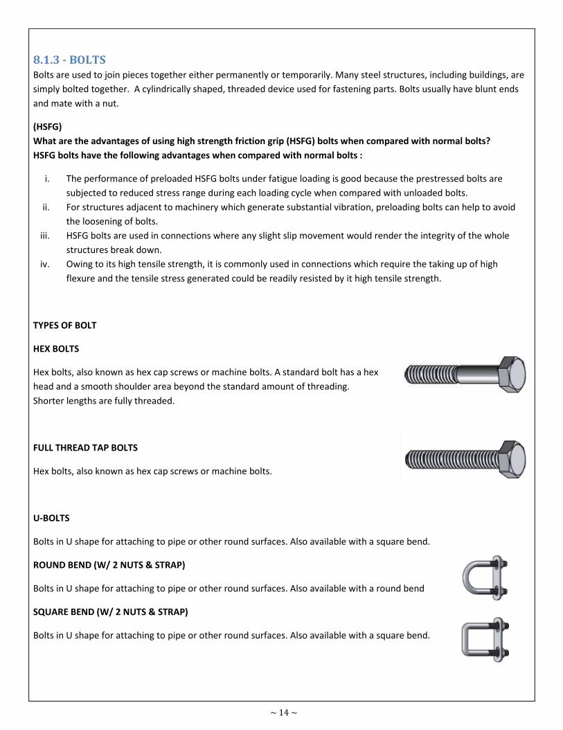
HEX BOLTS
Hex bolts, also known as hex cap screws or machine bolts. A standard bolt has a hex
head and a smooth shoulder area beyond the standard amount of threading.
Shorter lengths are fully threaded.
FULL THREAD TAP BOLTS
Hex bolts, also known as hex cap screws or machine bolts.
U-BOLTS
Bolts in U shape for attaching to pipe or other round surfaces. Also available with a square bend.
ROUND BEND (W/ 2 NUTS & STRAP)
Bolts in U shape for attaching to pipe or other round surfaces. Also available with a round bend
SQUARE BEND (W/ 2 NUTS & STRAP)
Bolts in U shape for attaching to pipe or other round surfaces. Also available with a square bend.
~ 15 ~
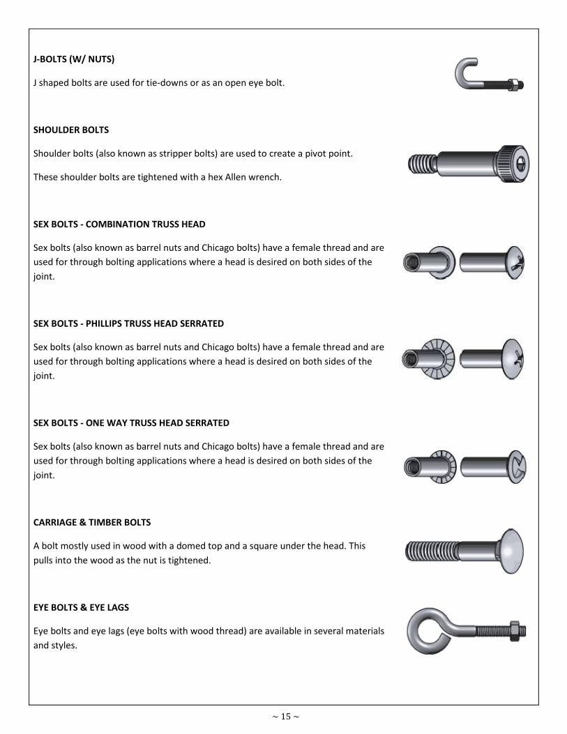
J-BOLTS (W/ NUTS)
J shaped bolts are used for tie-downs or as an open eye bolt.
SHOULDER BOLTS
Shoulder bolts (also known as stripper bolts) are used to create a pivot point.
These shoulder bolts are tightened with a hex Allen wrench.
SEX BOLTS - COMBINATION TRUSS HEAD
Sex bolts (also known as barrel nuts and Chicago bolts) have a female thread and are
used for through bolting applications where a head is desired on both sides of the
joint.
SEX BOLTS - PHILLIPS TRUSS HEAD SERRATED
Sex bolts (also known as barrel nuts and Chicago bolts) have a female thread and are
used for through bolting applications where a head is desired on both sides of the
joint.
SEX BOLTS - ONE WAY TRUSS HEAD SERRATED
Sex bolts (also known as barrel nuts and Chicago bolts) have a female thread and are
used for through bolting applications where a head is desired on both sides of the
joint.
CARRIAGE & TIMBER BOLTS
A bolt mostly used in wood with a domed top and a square under the head. This
pulls into the wood as the nut is tightened.
EYE BOLTS & EYE LAGS
Eye bolts and eye lags (eye bolts with wood thread) are available in several materials
and styles.
~ 16 ~
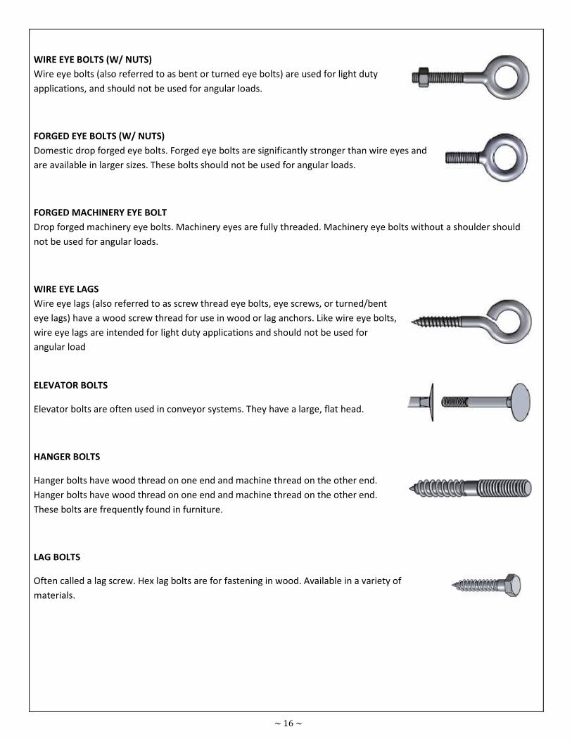
WIRE EYE BOLTS (W/ NUTS)
Wire eye bolts (also referred to as bent or turned eye bolts) are used for light duty
applications, and should not be used for angular loads.
FORGED EYE BOLTS (W/ NUTS)
Domestic drop forged eye bolts. Forged eye bolts are significantly stronger than wire eyes and
are available in larger sizes. These bolts should not be used for angular loads.
FORGED MACHINERY EYE BOLT
Drop forged machinery eye bolts. Machinery eyes are fully threaded. Machinery eye bolts without a shoulder should
not be used for angular loads.
WIRE EYE LAGS
Wire eye lags (also referred to as screw thread eye bolts, eye screws, or turned/bent
eye lags) have a wood screw thread for use in wood or lag anchors. Like wire eye bolts,
wire eye lags are intended for light duty applications and should not be used for
angular load
ELEVATOR BOLTS
Elevator bolts are often used in conveyor systems. They have a large, flat head.
HANGER BOLTS
Hanger bolts have wood thread on one end and machine thread on the other end.
Hanger bolts have wood thread on one end and machine thread on the other end.
These bolts are frequently found in furniture.
LAG BOLTS
Often called a lag screw. Hex lag bolts are for fastening in wood. Available in a variety of
materials.
~ 17 ~
8.1.4 - SCREW
A threaded cylindrical pin or rod with a head at one end, engaging a threaded hole and used either as a fastener or as a
simple machine for applying power, as in a clamp, jack, etc. Compare bolt
MACHINE SCREW
CSK Head Machine Screw
Pan Head Machine Screw
Cheese Head Machine Screw
Raised Head Machine Screw
PHILLIPS HEAD SCREW
Raised Phillips Head Self Tapping Screw
CSK Phillips Head Machine Screw
Pan Phillips Head Machine Screw
CSK PHILLIPS Head Self Tapping Screw
Pan Phillips Head Self
Self Tapping Screw
CSK Head Self Tapping Screw
Pan Head Self Tapping Screw
Round Head Self Tapping Screw
Raised Head Self Tapping Screw
Cheese Head Self Tapping Screw
WOOD SCREW
CSK Phillips Head Wood Screw
PHILLIPS PAN HEAD
A pan head screw protrudes above the surface of the material to be fastened.
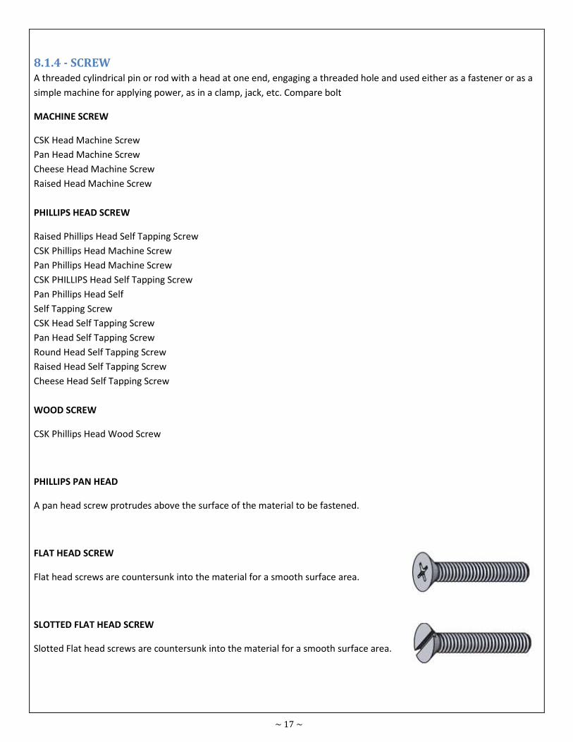
FLAT HEAD SCREW
Flat head screws are countersunk into the material for a smooth surface area.
SLOTTED FLAT HEAD SCREW
Slotted Flat head screws are countersunk into the material for a smooth surface area.
~ 18 ~
PHILLIPS OVAL HEAD
Oval head screws are similar to flat head, but have a slightly rounded top for a more
finished look.
SLOTTED OVAL HEAD
Oval head screws are similar to flat head, but have a slightly rounded top for a more
finished look.
SLOTTED ROUND HEAD
Round head protrudes above the surface of the material to be fastened.
COMBINATION ROUND HEAD
These are the same as round head except for the option of using either a slotted or
Phillips screwdriver.
COMBINATION TRUSS HEAD
Protrudes above the surface to be fastened but with a low profile and a larger surface
area under the head. Combination truss takes either a Phillips or slotted screwdriver.
SLOTTED TRUSS HEAD
Slotted truss head protrudes above the surface to be fastened but with a low profile
and a larger surface area under the head.
HEX SLOTTED WASHER HEAD THREAD CUTTING SCREW TYPE F
A hex head machine screw with a slotted and tapered point which is self tapping.
TORX FLAT HEAD THREAD CUTTING SCREW TYPE F
Also known as Trailer floor screws or Floor board screws these screws have a
countersunk head and a self tapping point.
~ 19 ~
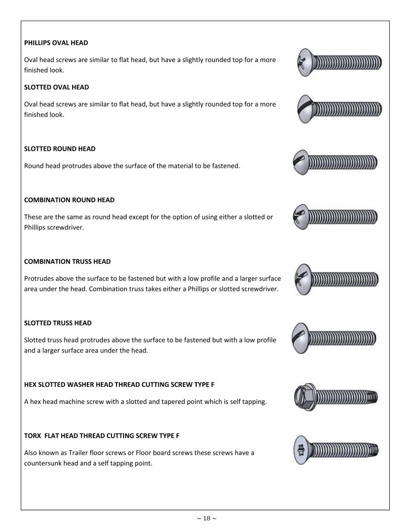
TORX PAN HEAD THREAD CUTTING SCREW TYPE F
These screws have a pan head and a self tapping point.
8.1.5 - WASHER
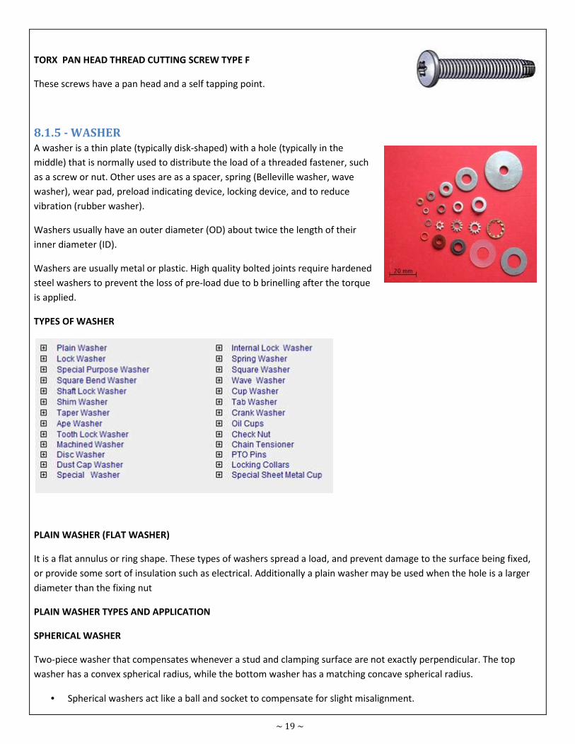
A washer is a thin plate (typically disk-shaped) with a hole (typically in the
middle) that is normally used to distribute the load of a threaded fastener, such
as a screw or nut. Other uses are as a spacer, spring (Belleville washer, wave
washer), wear pad, preload indicating device, locking device, and to reduce
vibration (rubber washer).
Washers usually have an outer diameter (OD) about twice the length of their
inner diameter (ID).
Washers are usually metal or plastic. High quality bolted joints require hardened
steel washers to prevent the loss of pre-load due to b brinelling after the torque
is applied.
TYPES OF WASHER
PLAIN WASHER (FLAT WASHER)
It is a flat annulus or ring shape. These types of washers spread a load, and prevent damage to the surface being fixed,
or provide some sort of insulation such as electrical. Additionally a plain washer may be used when the hole is a larger
diameter than the fixing nut
PLAIN WASHER TYPES AND APPLICATION
SPHERICAL WASHER
Two-piece washer that compensates whenever a stud and clamping surface are not exactly perpendicular. The top
washer has a convex spherical radius, while the bottom washer has a matching concave spherical radius.
• Spherical washers act like a ball and socket to compensate for slight misalignment.
~ 20 ~
• Use in pairs, or use the bottom with our spherical flange nuts.
• Carburized hardened steel.
ANCHOR PLATE (WALL WASHER)
It is a large plate or washer connected to a tie rod or bolt. Anchor plates are used on exterior walls of masonry
buildings, for structural reinforcement. Being visible, many anchor plates are made in a style that is decorative
A FLANGE NUT
It is a nut with an integral fixed washer.
TORQUE WASHER
It is used in woodworking in combination with a carriage bolt. It has a square hole in the center where the carriage bolt
square fits into. Teeth or prongs on the washer bite into the wood preventing the bolt from revolving freely when a nut
is being tightened.
SPRING WASHERS
These types of washers have axial flexibility and are used to prevent fastening loosening due to vibrations; and locking
washers which prevent fastening loosening by preventing unscrewing rotation of the fastening device; locking washers
as usually also spring washers. The term washer is also often used for disc shaped devices used as grommets.
TYPES AND APPLICATION
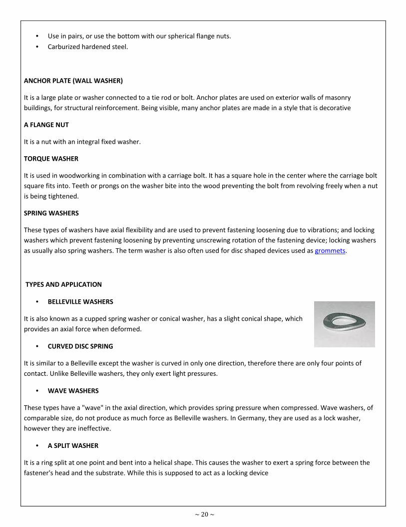
• BELLEVILLE WASHERS
It is also known as a cupped spring washer or conical washer, has a slight conical shape, which
provides an axial force when deformed.
• CURVED DISC SPRING
It is similar to a Belleville except the washer is curved in only one direction, therefore there are only four points of
contact. Unlike Belleville washers, they only exert light pressures.
• WAVE WASHERS
These types have a "wave" in the axial direction, which provides spring pressure when compressed. Wave washers, of
comparable size, do not produce as much force as Belleville washers. In Germany, they are used as a lock washer,
however they are ineffective.
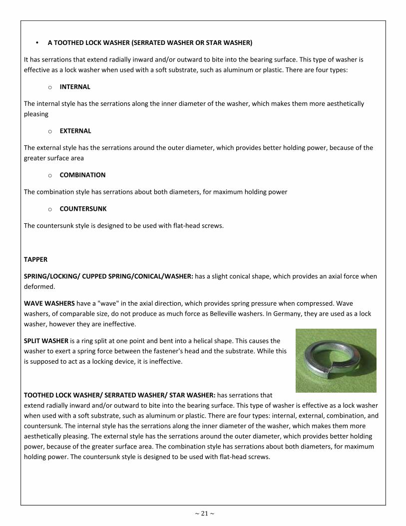
• A SPLIT WASHER
It is a ring split at one point and bent into a helical shape. This causes the washer to exert a spring force between the
fastener's head and the substrate. While this is supposed to act as a locking device
~ 21 ~
• A TOOTHED LOCK WASHER (SERRATED WASHER OR STAR WASHER)
It has serrations that extend radially inward and/or outward to bite into the bearing surface. This type of washer is
effective as a lock washer when used with a soft substrate, such as aluminum or plastic. There are four types:
o INTERNAL
The internal style has the serrations along the inner diameter of the washer, which makes them more aesthetically
pleasing
o EXTERNAL
The external style has the serrations around the outer diameter, which provides better holding power, because of the
greater surface area
o COMBINATION
The combination style has serrations about both diameters, for maximum holding power
o COUNTERSUNK
The countersunk style is designed to be used with flat-head screws.
TAPPER
SPRING/LOCKING/ CUPPED SPRING/CONICAL/WASHER: has a slight conical shape, which provides an axial force when
deformed.
WAVE WASHERS have a "wave" in the axial direction, which provides spring pressure when compressed. Wave
washers, of comparable size, do not produce as much force as Belleville washers. In Germany, they are used as a lock
washer, however they are ineffective.
SPLIT WASHER is a ring split at one point and bent into a helical shape. This causes the
washer to exert a spring force between the fastener's head and the substrate. While this
is supposed to act as a locking device, it is ineffective.
TOOTHED LOCK WASHER/ SERRATED WASHER/ STAR WASHER: has serrations that
extend radially inward and/or outward to bite into the bearing surface. This type of washer is effective as a lock washer
when used with a soft substrate, such as aluminum or plastic. There are four types: internal, external, combination, and
countersunk. The internal style has the serrations along the inner diameter of the washer, which makes them more
aesthetically pleasing. The external style has the serrations around the outer diameter, which provides better holding
power, because of the greater surface area. The combination style has serrations about both diameters, for maximum
holding power. The countersunk style is designed to be used with flat-head screws.
~ 22 ~
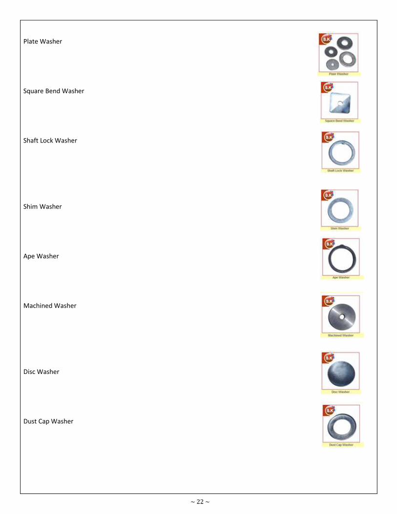
Plate Washer
Square Bend Washer
Shaft Lock Washer
Shim Washer
Ape Washer
Machined Washer
Disc Washer
Dust Cap Washer
~ 23 ~
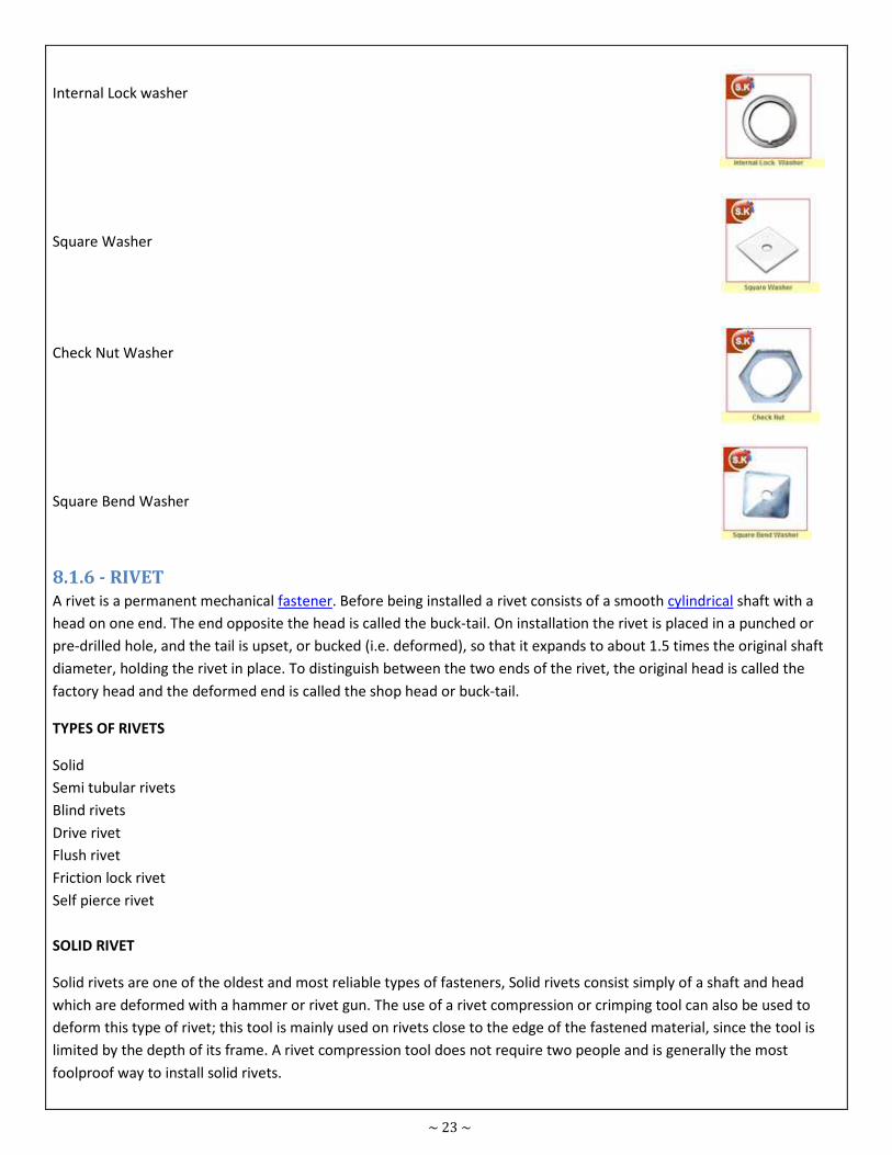
Internal Lock washer
Square Washer
Check Nut Washer
Square Bend Washer
8.1.6 - RIVET
A rivet is a permanent mechanical fastener. Before being installed a rivet consists of a smooth cylindrical shaft with a
head on one end. The end opposite the head is called the buck-tail. On installation the rivet is placed in a punched or
pre-drilled hole, and the tail is upset, or bucked (i.e. deformed), so that it expands to about 1.5 times the original shaft
diameter, holding the rivet in place. To distinguish between the two ends of the rivet, the original head is called the
factory head and the deformed end is called the shop head or buck-tail.
TYPES OF RIVETS
Solid
Semi tubular rivets
Blind rivets
Drive rivet
Flush rivet
Friction lock rivet
Self pierce rivet
SOLID RIVET
Solid rivets are one of the oldest and most reliable types of fasteners, Solid rivets consist simply of a shaft and head
which are deformed with a hammer or rivet gun. The use of a rivet compression or crimping tool can also be used to
deform this type of rivet; this tool is mainly used on rivets close to the edge of the fastened material, since the tool is
limited by the depth of its frame. A rivet compression tool does not require two people and is generally the most
foolproof way to install solid rivets.
~ 24 ~
APPLICATION
Solid rivets are used in applications where reliability and safety count. A typical application for solid rivets can be found
within the structural parts of:
Aircraft.
Hundreds of thousands of solid rivets are used to assemble the frame of a modern aircraft.
Bridges:
Crane
Building Frame
A countersink may be used in many tools, such as drills, drill presses, milling machines, and lathes
SEMI-TUBULAR RIVETS (TUBULAR RIVETS)
Semi-tubular rivets (also known as tubular rivets) are similar to solid rivets, except they have a partial hole (opposite
the head) at the tip. The purpose of this hole is to reduce the amount of force needed for application by rolling the
tubular portion outward. The force needed to apply a semitubular rivet is about 1/4 of the amount needed to apply a
solid rivet. Tubular rivets can also be used as pivot points (a joint where movement is preferred) since the swelling of
the rivet is only at the tail. Solid rivets expand radially and generally fill the hole limiting movement. The type of
equipment used to apply semi-tubular rivets range from prototyping tools (less than $50) to fully automated systems.
Typical installation tools (from lowest to highest price) are hand set, manual squeezer, pneumatic squeezer, kick press,
impact riveter, and finally PLC-controlled robotics. The most common machine is the impact riveter and the most
common use of semitubular rivets is in lighting, brakes, ladders, binders, HVAC duct work, mechanical products, and
electronics. They are offered from 1/16-inch (1.6 mm) to 3/8-inch (9.5 mm) in diameter (other sizes are considered
highly special) and can be up to 8 inches (203 mm) long. A wide variety of materials and platings are available, most
common base metals are steel, brass, copper, stainless, aluminum and most common platings are zinc, nickel, brass,
tin. All tubular rivets are waxed to facilitate proper assembly. The finished look of a tubular rivet will have a head on
one side, with a rolled over and exposed shallow blind hole on the other. Semi-tubular rivets are the fastest way to
rivet in mass production but require
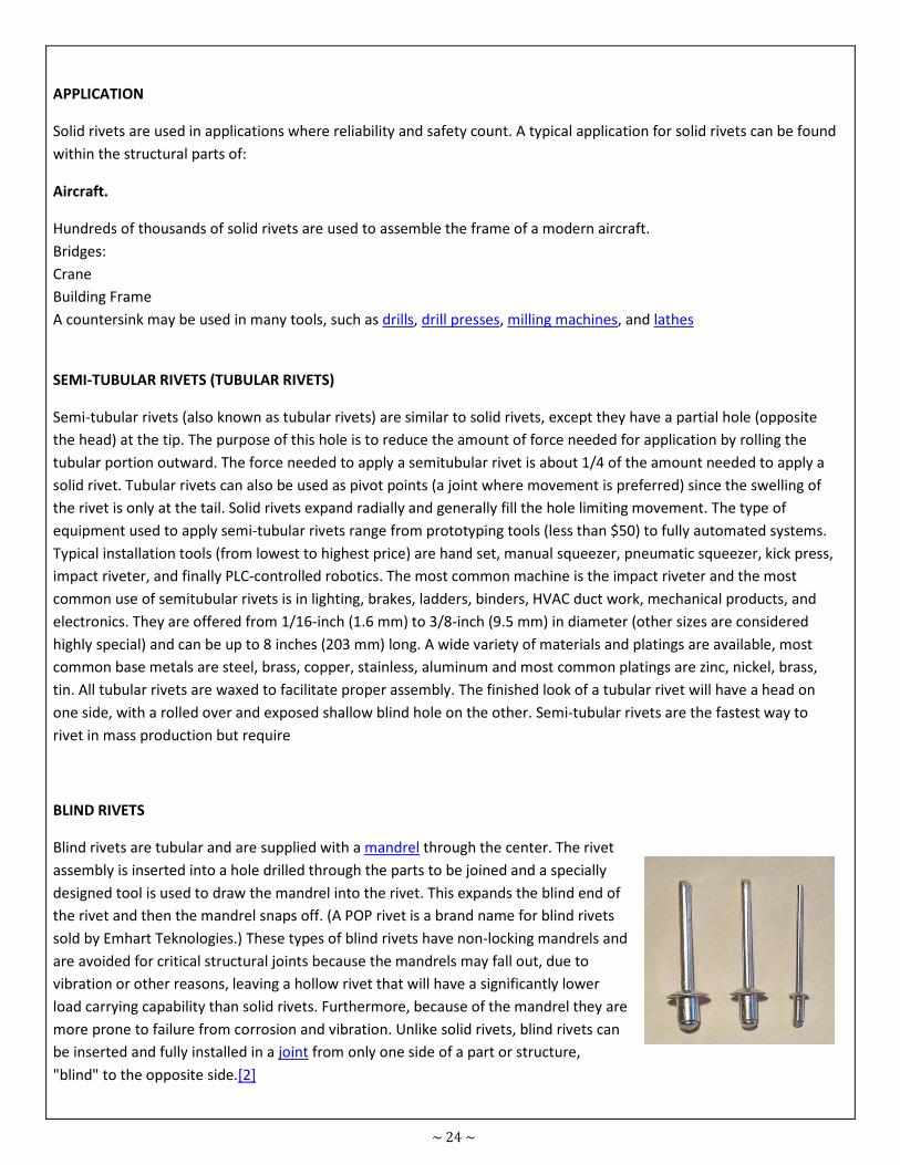
BLIND RIVETS
Blind rivets are tubular and are supplied with a mandrel through the center. The rivet
assembly is inserted into a hole drilled through the parts to be joined and a specially
designed tool is used to draw the mandrel into the rivet. This expands the blind end of
the rivet and then the mandrel snaps off. (A POP rivet is a brand name for blind rivets
sold by Emhart Teknologies.) These types of blind rivets have non-locking mandrels and
are avoided for critical structural joints because the mandrels may fall out, due to
vibration or other reasons, leaving a hollow rivet that will have a significantly lower
load carrying capability than solid rivets. Furthermore, because of the mandrel they are
more prone to failure from corrosion and vibration. Unlike solid rivets, blind rivets can
be inserted and fully installed in a joint from only one side of a part or structure,
"blind" to the opposite side.[2]
~ 25 ~
Prior to the adoption of blind rivets, installation of a solid rivet typically required two assemblers: one person with a
rivet hammer on one side and a second person with a bucking bar on the other side. Seeking an alternative, inventors
such as Carl Cherry and Lou Huck experimented with other techniques for expanding solid rivets. The blind rivet was
developed by the United Shoe Machinery Corporation.[3]
Due to this feature, blind rivets are mainly used when access to the joint is only available from one side. The rivet is
placed in a pre-drilled hole and is set by pulling the mandrel head into the rivet body, expanding the rivet body and
causing it to flare against the reverse side. As the head of the mandrel reaches the face of the blind side material, the
pulling force is resisted, and at a predetermined force, the mandrel will snap at its break point, also called "Blind
Setting". A tight joint formed by the rivet body remains, the head of the mandrel remains encapsulated at the blind
side, although variations of this are available, and the mandrel stem is ejected.
Most blind rivets have limited use on aircraft and are never used for structural repairs. However, they are useful for
temporarily lining up holes. In addition, some "home built" aircraft use blind rivets. They are available in flat head,
countersunk head, and modified flush head with standard diameters of 1/8, 5/32 and 3/16 inch. Blind rivets are made
from soft aluminum alloy, steel (including stainless steel), copper, and Monel.
The rivet body is normally manufactured using one of three methods:
DRIVE RIVET
A drive rivet is a form of blind rivet that has a short mandrel protruding from the head that is driven in with a hammer
to flare out the end inserted in the hole. This is commonly used to rivet wood panels into place since the hole does not
need to be drilled all the way through the panel, producing an aesthetically pleasing appearance. They can also be used
with plastic, metal, and other materials and require no special setting tool other than a hammer and possibly a backing
block (steel or some other dense material) placed behind the location of the rivet while hammering it into place. Drive
rivets have less clamping force than most other rivets.
FLUSH RIVET
A flush rivet is used primarily on external metal surfaces where good appearance and the elimination of unnecessary
aerodynamic drag are important. A flush rivet takes advantage of a countersink hole, they are also commonly referred
to as countersunk rivets. Countersunk or flush rivets are used extensively on the exterior of aircraft for aerodynamic
reasons. Additional post-installation machining may be performed to perfect the airflow.
FRICTION - LOCK RIVET
One early form of blind rivet that was the first to be widely used for aircraft construction and repair was the Cherry
friction-lock rivet. Originally, Cherry friction-locks were available in two styles, hollow shank pull-through and self-
plugging types. The pull-through type is no longer common, however, the self -plugging Cherry friction-lock rivet is still
used for repairing light aircraft.
Cherry friction-lock rivets are available in two head styles, universal and 100 degree countersunk. Furthermore, they
are usually supplied in three standard diameters, 1/8, 5/32 and 3/16 inch.
A friction-lock rivet cannot replace a solid shank rivet, size for size. When a friction-lock is used to replace a solid shank
rivet, it must be at least one size larger in diameter. the reason behind this is that friction-lock rivet loses considerable
strength if its center stem falls out due to vibrations or damage.
Rivet alloys, their shear strengths and condition in which they are driven.
~ 26 ~
SELF PIERCE RIVET
Self-pierce riveting (SPR) is a process of joining two or more materials using an engineered rivet. Unlike solid, blind and
semi-tubular rivets, self-pierce rivets do not require a drilled or punched hole.
SPRs are cold forged to a semi-tubular shape and contain a partial hole to the opposite end of the head. The end
geometry of the rivet has a chamfered poke which aids the piercing of the materials being joined, a hydraulic or electric
servo rivet setter drives the rivet into the material and an upsetting die provides a cavity for the displaced bottom sheet
material to flow.
The self-pierce rivet fully pierces the top sheet material(s) but only partially pierces the bottom sheet. As the tail end of
the rivet does not break through the bottom sheet it provides a water or gas tight joint. With the influence of the
upsetting die, the tail end of the rivet flares and interlocks into the bottom sheet forming a low profile button.
Rivets need to be harder than the materials being joined, they are heat treated to various levels of hardness depending
on the materials ductility and hardness. Rivets come in a range of diameters and lengths depending on the materials
being joined, head styles are either flush countersunk or pan heads.
Depending on the rivet setter configuration, i.e. hydraulic, servo, stroke, nose-to-die gap, feed system etc., cycle times
can be as quick as one second. Rivets are typically fed to the rivet setter nose from tape and come in cassette or spool
form for continuous production.
Riveting systems can be manual or automated depending on the application requirements, all systems are very flexible
in terms of product design and ease of integration into a manufacturing process.
SPR joins a range of dissimilar materials such as steel, aluminum, plastics, composites and pre-coated or pre-painted
materials. Benefits include low energy demands, no heat, fumes, sparks or waste and very repeatable quality.
Such rivets come with rounded (universal) or 100° countersunk heads. Typical materials for aircraft rivets are
aluminium alloys (2017, 2024, 2117, 7050, 5056, 55000, V-65), titanium, and nickel-based alloys (e.g. Monel). Some
aluminum alloy rivets are too hard to buck and must be softened by annealing prior to being bucked. "Ice box"
aluminum alloy rivets harden with age, and must likewise be annealed and then kept at sub-freezing temperatures
(hence the name "ice box") to slow the age-hardening process. Steel rivets can be found in static structures such as
bridges, cranes, and building frames.
The setting of these fasteners requires access to both sides of a structure. Solid rivets are driven using a hydraulically,
pneumatically, or electromagnetically driven squeezing tool or even a handheld hammer. Applications in which only
one side is accessible require the use of blind rivets.
RIVET TYPES
Solid
Snap or Round
Flat
Tubular (POP)
BLIND RIVETS (open or closed end)
They are used for blind fastening where there is no access to the opposite side of the work.
~ 27 ~
BULB -TITE RIVETS
The Bulb - Tite rivet body folds into three separate legs forming a large blind-side head. This large bearing head evenly
distributes the Bulb-Tite's clamp force in soft, thin or brittle materials while providing high pull-through resistance. The
Bulb-tite's wide grip range enables a single Bulb-Tite to work in a greater variation of thicknesses.
BUTTONHEAD RIVETS (open end, blind / pop rivets / break-stem rivets)
They are used for blind fastening where there is no access to the opposite side of the work. These have a low profile
head diameter which is about twice the rivet body diameter, providing adequate bearing surface.
CLOSED END RIVETS
These are moisture resistant due to the closed end and tight seal. They also have greater shear strength. Sizes are 1/8
to1/4" diameter.
EXTRA-LONG / METRIC RIVETS
We provide metric blind rivets according to DIN7337 standards in 3mm, 4mm and 5mm diameters. Standard material
is Aluminum/Steel. Stainless Steel 304 and 316 alloys are available upon special request. All dimensions for Metric
Series are given in millimeters. Additional diameters of 4.8mm, 6mm and 6.4mm available on special request.
LARGE FLANGE RIVETS
Provide greater bearing surface for fastening soft and brittle facing materials and oversize facing holes. Multi-Grip
Rivets have extended grip range capacity. They reduce the inventory of sizes needed to keep on hand.
MEGA-GRIP RIVETS
The Mega-Grip rivet is a high strength structural blind rivet offering several advantages over conventional blind rivets.
Mega-Grip's wide grip range enables a single Mega-Grip to replace up to five different lengths of standard rivets. High
shear strength is achieved by Mega-Grip's flush break self plugging mandrel. Mega-Grip rivets are hole-filling, resulting
in tighter joints and improved sealing for weather resistance. Mega-Grip rivets are installed via standard rivet tools and
do not require special nose tips.
MULTI GRIP RIVETS
Rivets have a wider grip range than standard blind rivets and several other advantages. The "bulbing" action of a
multigrip blind rivet ensures complete hole fill even in oversized, irregular or misaligned holes, provides high clamp-up
and high shear strength and ensures positive stem (mandrel) retention, plugging the end of the rivet body and
providing a vibration and weather-proof seal. Due to the Multi-Grip blind rivets extended grip range capacity, Multi
Grip Rivets reduce the inventory of sizes needed to keep on hand. We stock aluminum-steel Multi grip rivets. PolyGrip
multi-grip rivets feature a wide grip range, enabling a single PolyGrip to replace up to three different lengths of
standard blind rivets. PolyGrip rivets expand radially, filling the application hole, resulting in tighter joints and improved
sealing. The PolyGrip's locked mandrel core creates a weather resistant fastener. Improved material support is provided
by the PolyGrip's larger blindside head formation. Large flange head style available upon request.
OPEN END RIVETS
These are the standard design and are available in a wide variety of sizes and materials, for most any application.
~ 28 ~
PLASTIC RIVETS:
Precision Molded, all nylon. Secure lock feature prevents pull-out. Used for fastening plastic to plastic, plastic to metal
or fiberglass.
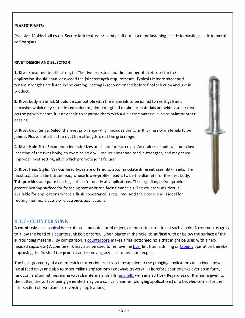
RIVET DESIGN AND SELECTION:
1. Rivet shear and tensile strength: The rivet selected and the number of rivets used in the
application should equal or exceed the joint strength requirements. Typical ultimate shear and
tensile strengths are listed in the catalog. Testing is recommended before final selection and use in
product.
2. Rivet body material: Should be compatible with the materials to be joined to resist galvanic
corrosion which may result in reduction of joint strength. If dissimilar materials are widely separated
on the galvanic chart, it is advisable to separate them with a dielectric material such as paint or other
coating.
3. Rivet Grip Range: Select the rivet grip range which includes the total thickness of materials to be
joined. Please note that the rivet barrel length is not the grip range.
4. Rivet Hole Size: Recommended hole sizes are listed for each rivet. An undersize hole will not allow
insertion of the rivet body; an oversize hole will reduce shear and tensile strengths, and may cause
improper rivet setting, all of which promote joint failure.
5. Rivet Head Style: Various head types are offered to accommodate different assembly needs. The
most popular is the buttonhead, whose lower-profile head is twice the diameter of the rivet body.
This provides adequate bearing surface for nearly all applications. The large flange rivet provides
greater bearing surface for fastening soft or brittle facing materials. The countersunk rivet is
available for applications where a flush appearance is required. And the closed-end is ideal for
roofing, marine, electric or electronics applications.
8.1.7 - COUNTER SUNK
A countersink is a conical hole cut into a manufactured object, or the cutter used to cut such a hole. A common usage is
to allow the head of a countersunk bolt or screw, when placed in the hole, to sit flush with or below the surface of the
surrounding material. (By comparison, a counterbore makes a flat-bottomed hole that might be used with a hex-
headed capscrew.) A countersink may also be used to remove the burr left from a drilling or tapping operation thereby
improving the finish of the product and removing any hazardous sharp edges.
The basic geometry of a countersink (cutter) inherently can be applied to the plunging applications described above
(axial feed only) and also to other milling applications (sideways traversal). Therefore countersinks overlap in form,
function, and sometimes name with chamfering endmills (endmills with angled tips). Regardless of the name given to
the cutter, the surface being generated may be a conical chamfer (plunging applications) or a beveled corner for the
intersection of two planes (traversing applications).
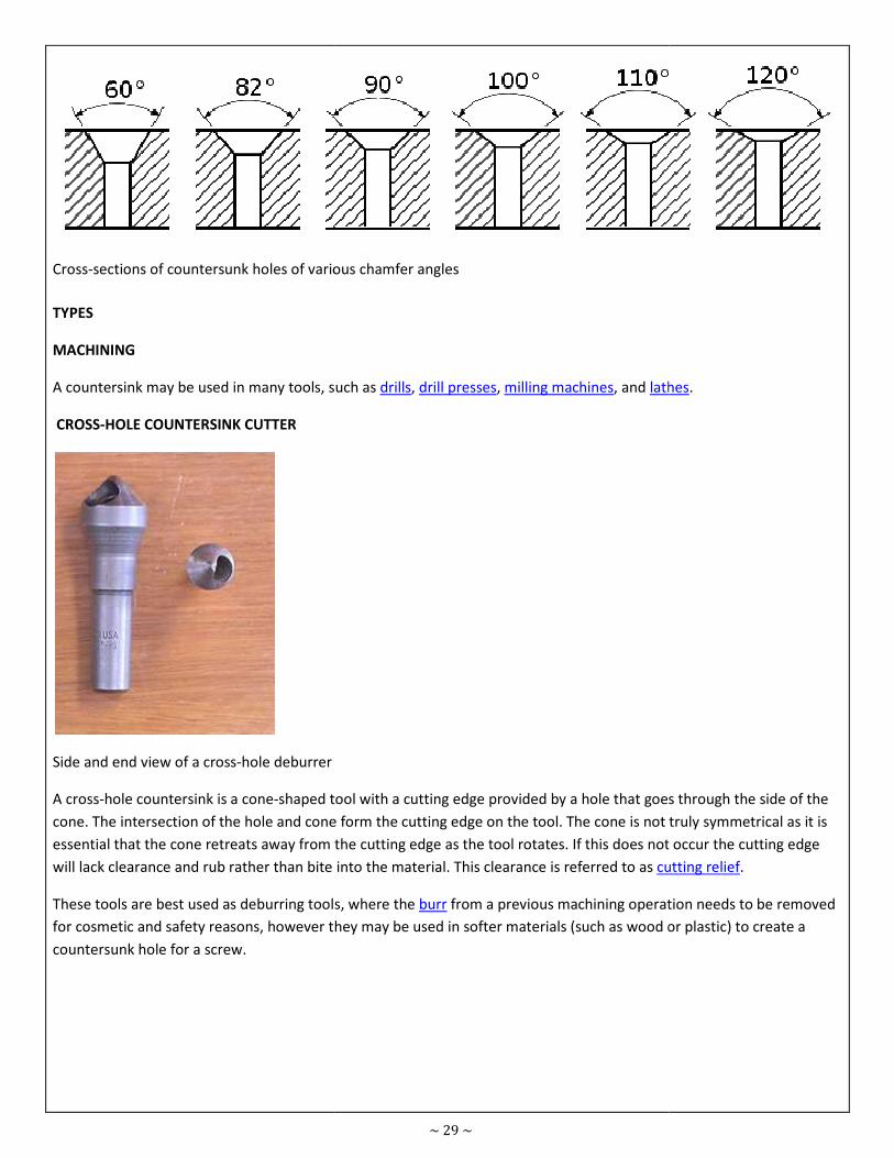
Cross-sections of countersunk holes of various chamfer angles
TYPES
MACHINING
A countersink may be used in many tools, such as
CROSS-HOLE COUNTERSINK CUTTER
Side and end view of a cross-hole deburrer
A cross-hole countersink is a cone-shaped tool with a cutting edge provided by a hole that goes through the side of the
cone. The intersection of the hole and cone form the cutting edge on the tool. The cone is not truly symmetrical as it is
essential that the cone retreats away from the cutting edge as the tool rotates. If this does not occur the cutting edge
will lack clearance and rub rather than bite into the material. This clearance is referred to as
These tools are best used as deburring tools, where the
for cosmetic and safety reasons, however they may be used in softer materials (such as wood or plastic) to create a
countersunk hole for a screw.
~ 29 ~
sections of countersunk holes of various chamfer angles
A countersink may be used in many tools, such as drills, drill presses, milling machines, and lathes
shaped tool with a cutting edge provided by a hole that goes through the side of the
cone. The intersection of the hole and cone form the cutting edge on the tool. The cone is not truly symmetrical as it is
the cone retreats away from the cutting edge as the tool rotates. If this does not occur the cutting edge
will lack clearance and rub rather than bite into the material. This clearance is referred to as cutting relief
These tools are best used as deburring tools, where the burr from a previous machining operation needs to be removed
for cosmetic and safety reasons, however they may be used in softer materials (such as wood or plastic) to create a
lathes.
shaped tool with a cutting edge provided by a hole that goes through the side of the
cone. The intersection of the hole and cone form the cutting edge on the tool. The cone is not truly symmetrical as it is
the cone retreats away from the cutting edge as the tool rotates. If this does not occur the cutting edge
cutting relief.
chining operation needs to be removed
for cosmetic and safety reasons, however they may be used in softer materials (such as wood or plastic) to create a
~ 30 ~
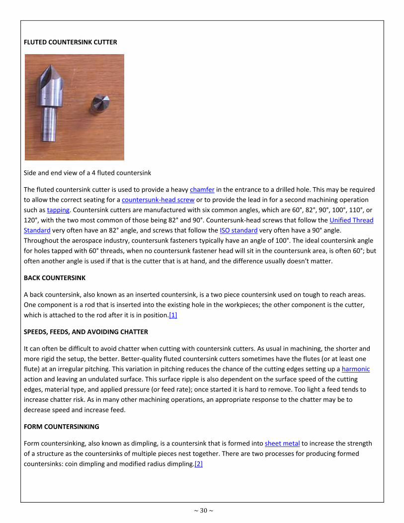
FLUTED COUNTERSINK CUTTER
Side and end view of a 4 fluted countersink
The fluted countersink cutter is used to provide a heavy chamfer in the entrance to a drilled hole. This may be required
to allow the correct seating for a countersunk-head screw or to provide the lead in for a second machining operation
such as tapping. Countersink cutters are manufactured with six common angles, which are 60°, 82°, 90°, 100°, 110°, or
120°, with the two most common of those being 82° and 90°. Countersunk-head screws that follow the Unified Thread
Standard very often have an 82° angle, and screws that follow the ISO standard very often have a 90° angle.
Throughout the aerospace industry, countersunk fasteners typically have an angle of 100°. The ideal countersink angle
for holes tapped with 60° threads, when no countersunk fastener head will sit in the countersunk area, is often 60°; but
often another angle is used if that is the cutter that is at hand, and the difference usually doesn't matter.
BACK COUNTERSINK
A back countersink, also known as an inserted countersink, is a two piece countersink used on tough to reach areas.
One component is a rod that is inserted into the existing hole in the workpieces; the other component is the cutter,
which is attached to the rod after it is in position.[1]
SPEEDS, FEEDS, AND AVOIDING CHATTER
It can often be difficult to avoid chatter when cutting with countersink cutters. As usual in machining, the shorter and
more rigid the setup, the better. Better-quality fluted countersink cutters sometimes have the flutes (or at least one
flute) at an irregular pitching. This variation in pitching reduces the chance of the cutting edges setting up a harmonic
action and leaving an undulated surface. This surface ripple is also dependent on the surface speed of the cutting
edges, material type, and applied pressure (or feed rate); once started it is hard to remove. Too light a feed tends to
increase chatter risk. As in many other machining operations, an appropriate response to the chatter may be to
decrease speed and increase feed.
FORM COUNTERSINKING
Form countersinking, also known as dimpling, is a countersink that is formed into sheet metal to increase the strength
of a structure as the countersinks of multiple pieces nest together. There are two processes for producing formed
countersinks: coin dimpling and modified radius dimpling.[2]
~ 31 ~
Fastening & Joining Module
No. 8.02
Prepared
by Nisar Ahmad
Course Certificate in Engineering Skills Duration 60 - Mins
Teaching Aid
Topic Identify types and applications of screw threads
8.2 - IDENTIFY TYPES AND APPLICATIONS OF SCREW THREADS
8.2.1 - SCREW THREAD
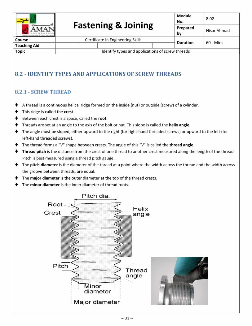
� A thread is a continuous helical ridge formed on the inside (nut) or outside (screw) of a cylinder.
� This ridge is called the crest.
� Between each crest is a space, called the root.
� Threads are set at an angle to the axis of the bolt or nut. This slope is called the helix angle.
� The angle must be sloped, either upward to the right (for right-hand threaded screws) or upward to the left (for
left-hand threaded screws).
� The thread forms a "V" shape between crests. The angle of this "V" is called the thread angle.
� Thread pitch is the distance from the crest of one thread to another crest measured along the length of the thread.
Pitch is best measured using a thread pitch gauge.
� The pitch diameter is the diameter of the thread at a point where the width across the thread and the width across
the groove between threads, are equal.
� The major diameter is the outer diameter at the top of the thread crests.
� The minor diameter is the inner diameter of thread roots.
~ 32 ~
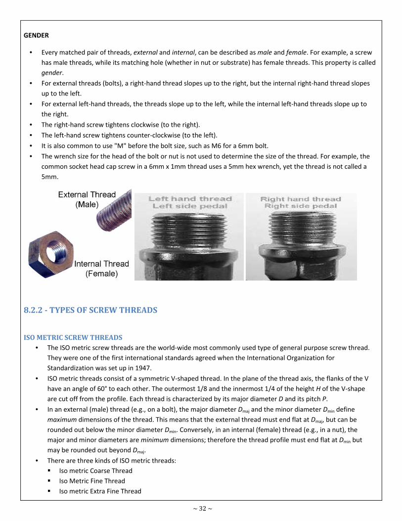
GENDER
• Every matched pair of threads, external and internal, can be described as male and female. For example, a screw
has male threads, while its matching hole (whether in nut or substrate) has female threads. This property is called
gender.
• For external threads (bolts), a right-hand thread slopes up to the right, but the internal right-hand thread slopes
up to the left.
• For external left-hand threads, the threads slope up to the left, while the internal left-hand threads slope up to
the right.
• The right-hand screw tightens clockwise (to the right).
• The left-hand screw tightens counter-clockwise (to the left).
• It is also common to use "M" before the bolt size, such as M6 for a 6mm bolt.
• The wrench size for the head of the bolt or nut is not used to determine the size of the thread. For example, the
common socket head cap screw in a 6mm x 1mm thread uses a 5mm hex wrench, yet the thread is not called a
5mm.
8.2.2 - TYPES OF SCREW THREADS
ISO METRIC SCREW THREADS
• The ISO metric screw threads are the world-wide most commonly used type of general purpose screw thread.
They were one of the first international standards agreed when the International Organization for
Standardization was set up in 1947.
• ISO metric threads consist of a symmetric V-shaped thread. In the plane of the thread axis, the flanks of the V
have an angle of 60° to each other. The outermost 1/8 and the innermost 1/4 of the height H of the V-shape
are cut off from the profile. Each thread is characterized by its major diameter D and its pitch P.
• In an external (male) thread (e.g., on a bolt), the major diameter Dmaj and the minor diameter Dmin define
maximum dimensions of the thread. This means that the external thread must end flat at Dmaj, but can be
rounded out below the minor diameter Dmin. Conversely, in an internal (female) thread (e.g., in a nut), the
major and minor diameters are minimum dimensions; therefore the thread profile must end flat at Dmin but
may be rounded out beyond Dmaj.
• There are three kinds of ISO metric threads:
� Iso metric Coarse Thread
� Iso Metric Fine Thread
� Iso metric Extra Fine Thread
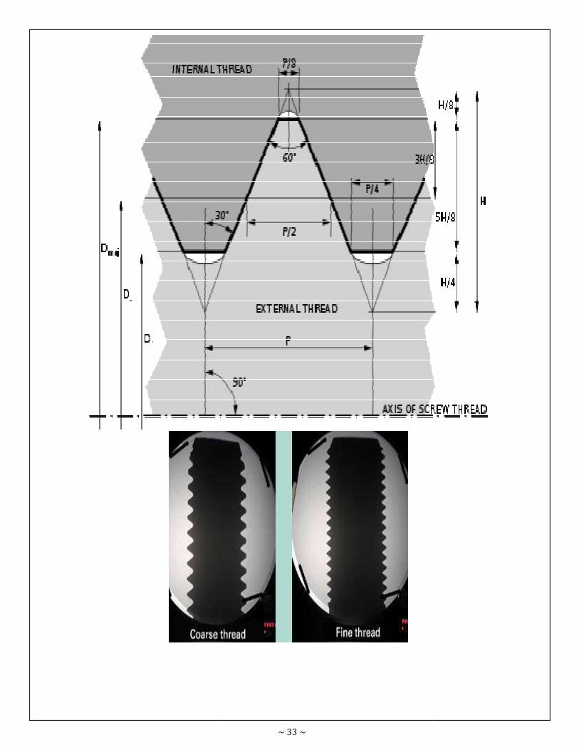
~ 33 ~
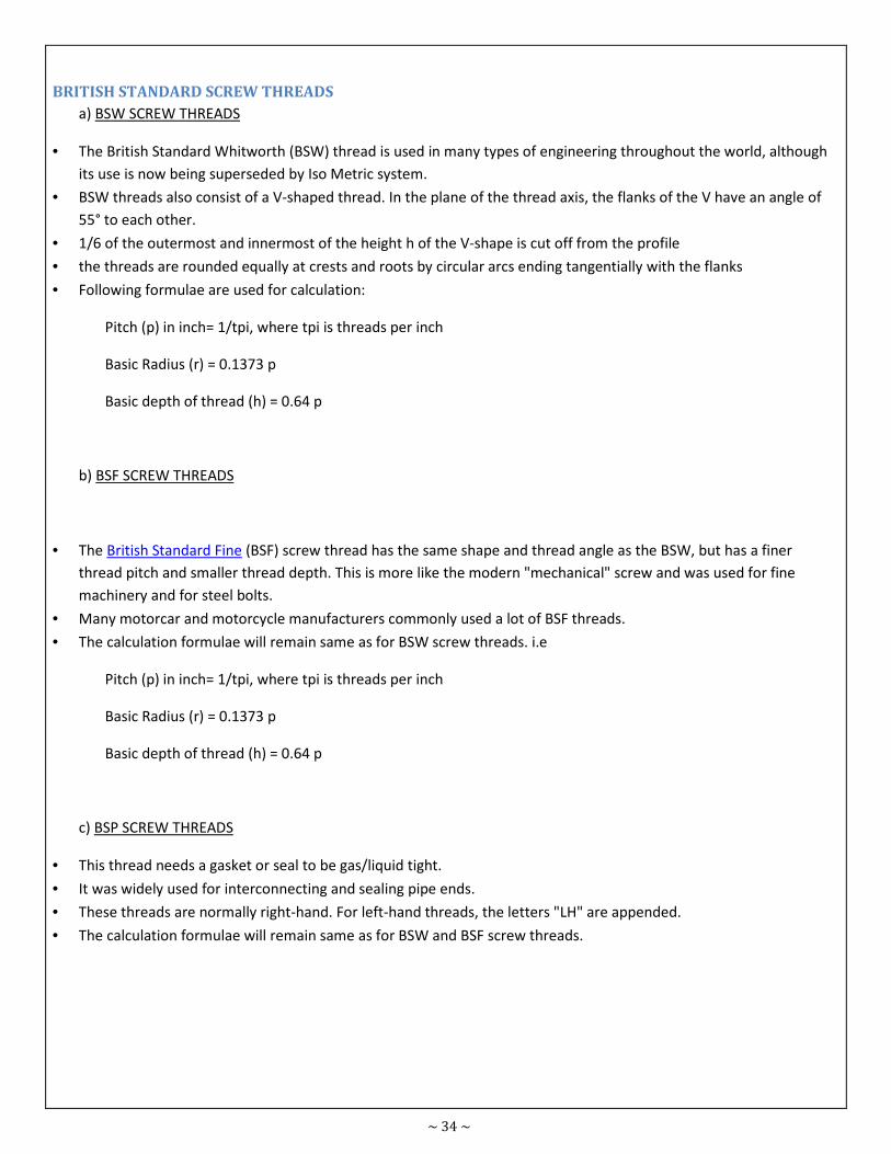
~ 34 ~
BRITISH STANDARD SCREW THREADS
a) BSW SCREW THREADS
• The British Standard Whitworth (BSW) thread is used in many types of engineering throughout the world, although
its use is now being superseded by Iso Metric system.
• BSW threads also consist of a V-shaped thread. In the plane of the thread axis, the flanks of the V have an angle of
55° to each other.
• 1/6 of the outermost and innermost of the height h of the V-shape is cut off from the profile
• the threads are rounded equally at crests and roots by circular arcs ending tangentially with the flanks
• Following formulae are used for calculation:
Pitch (p) in inch= 1/tpi, where tpi is threads per inch
Basic Radius (r) = 0.1373 p
Basic depth of thread (h) = 0.64 p
b) BSF SCREW THREADS
• The British Standard Fine (BSF) screw thread has the same shape and thread angle as the BSW, but has a finer
thread pitch and smaller thread depth. This is more like the modern "mechanical" screw and was used for fine
machinery and for steel bolts.
• Many motorcar and motorcycle manufacturers commonly used a lot of BSF threads.
• The calculation formulae will remain same as for BSW screw threads. i.e
Pitch (p) in inch= 1/tpi, where tpi is threads per inch
Basic Radius (r) = 0.1373 p
Basic depth of thread (h) = 0.64 p
c) BSP SCREW THREADS
• This thread needs a gasket or seal to be gas/liquid tight.
• It was widely used for interconnecting and sealing pipe ends.
• These threads are normally right-hand. For left-hand threads, the letters "LH" are appended.
• The calculation formulae will remain same as for BSW and BSF screw threads.
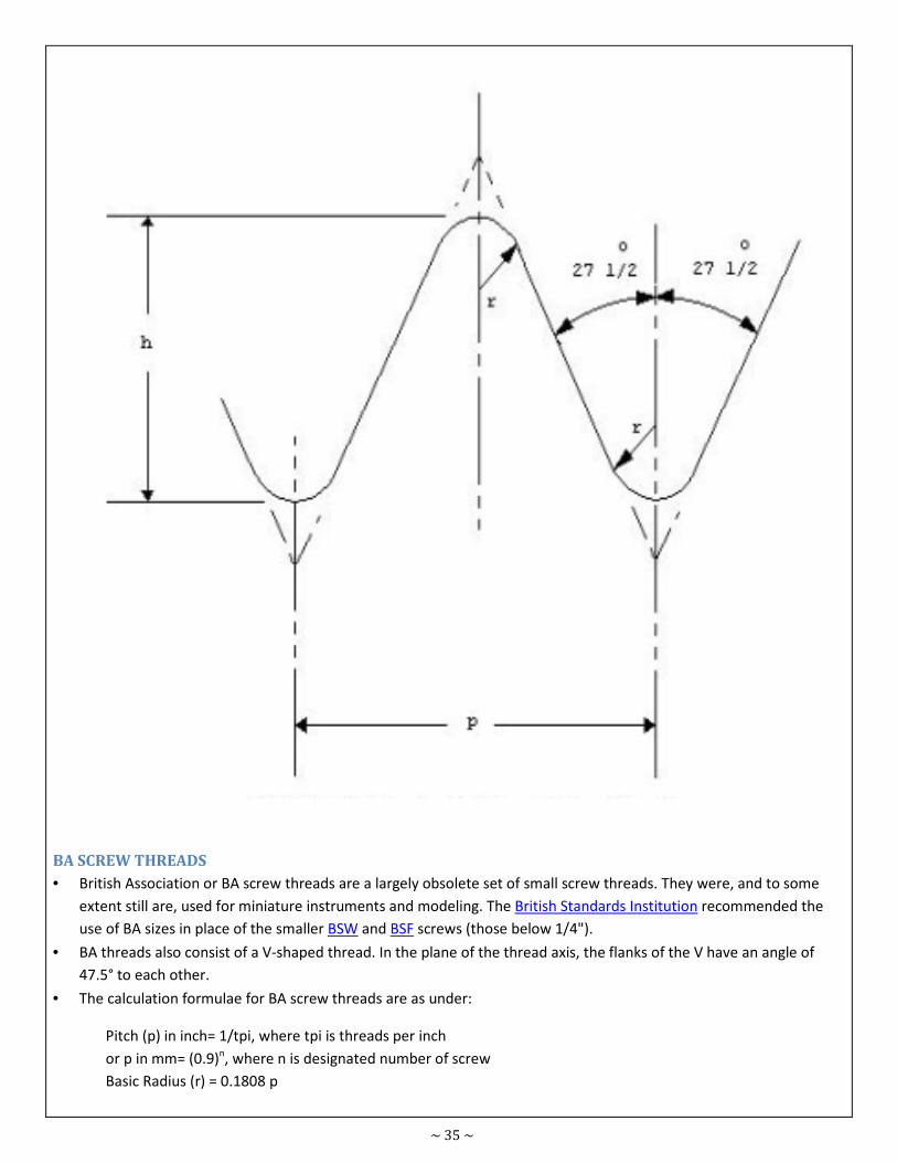
~ 35 ~
BA SCREW THREADS
• British Association or BA screw threads are a largely obsolete set of small screw threads. They were, and to some
extent still are, used for miniature instruments and modeling. The British Standards Institution recommended the
use of BA sizes in place of the smaller BSW and BSF screws (those below 1/4").
• BA threads also consist of a V-shaped thread. In the plane of the thread axis, the flanks of the V have an angle of
47.5° to each other.
• The calculation formulae for BA screw threads are as under:
Pitch (p) in inch= 1/tpi, where tpi is threads per inch
or p in mm= (0.9)n, where n is designated number of screw
Basic Radius (r) = 0.1808 p
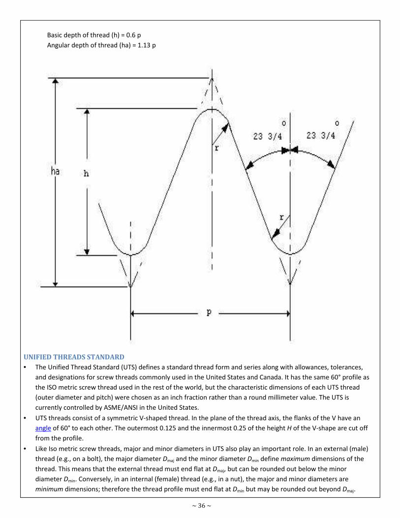
~ 36 ~
Basic depth of thread (h) = 0.6 p
Angular depth of thread (ha) = 1.13 p
UNIFIED THREADS STANDARD
• The Unified Thread Standard (UTS) defines a standard thread form and series along with allowances, tolerances,
and designations for screw threads commonly used in the United States and Canada. It has the same 60° profile as
the ISO metric screw thread used in the rest of the world, but the characteristic dimensions of each UTS thread
(outer diameter and pitch) were chosen as an inch fraction rather than a round millimeter value. The UTS is
currently controlled by ASME/ANSI in the United States.
• UTS threads consist of a symmetric V-shaped thread. In the plane of the thread axis, the flanks of the V have an
angle of 60° to each other. The outermost 0.125 and the innermost 0.25 of the height H of the V-shape are cut off
from the profile.
• Like Iso metric screw threads, major and minor diameters in UTS also play an important role. In an external (male)
thread (e.g., on a bolt), the major diameter Dmaj and the minor diameter Dmin define maximum dimensions of the
thread. This means that the external thread must end flat at Dmaj, but can be rounded out below the minor
diameter Dmin. Conversely, in an internal (female) thread (e.g., in a nut), the major and minor diameters are
minimum dimensions; therefore the thread profile must end flat at Dmin but may be rounded out beyond Dmaj.
~ 37 ~
• The two types of UTS threads are:
� Unified National Fine (UNF) Thread
� Unified National Coarse (UNC) Thread
• The basic profile of both UNF and UNC is same. The calculation formulae for these threads are as under:
Pitch (p) in inch= 1/tpi, where tpi is threads per inch
Basic radius (r) = 0.1443 p
Basic height of internal thread (hn) = 0.54 p
Basic height of external thread (hs) = 0.61 p
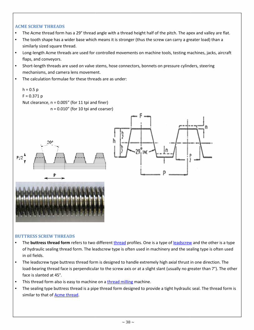
ACME SCREW THREADS
• The Acme thread form has a 29° thread angle
• The tooth shape has a wider base which means it is stronger (thus the screw can carry a greater load) than a
similarly sized square thread.
• Long-length Acme threads are used for controlled movements on
flaps, and conveyors.
• Short-length threads are used on valve stems, hose connectors, bonnets on pressure cylinders, steering
mechanisms, and camera lens movement.
• The calculation formulae for these threads a
h = 0.5 p
F = 0.371 p
Nut clearance, n = 0.005” (for 11 tpi and finer)
n = 0.010” (for 10 tpi and coarser)
BUTTRESS SCREW THREADS
• The buttress thread form refers to two different
of hydraulic sealing thread form. The leadscrew type is often u
in oil fields.
• The leadscrew type buttress thread form is designed to handle extremely high axial thrust in one direction. The
load-bearing thread face is perpendicular to the screw axis or at a slight sl
face is slanted at 45°.
• This thread form also is easy to machine on a
• The sealing type buttress thread is a pipe thread form designed to provide a tight hydraulic seal. The thread form is
similar to that of Acme thread.
~ 38 ~
thread angle with a thread height half of the pitch. The apex and valley are flat.
The tooth shape has a wider base which means it is stronger (thus the screw can carry a greater load) than a
length Acme threads are used for controlled movements on machine tools, testing machines, jacks, aircraft
length threads are used on valve stems, hose connectors, bonnets on pressure cylinders, steering
mechanisms, and camera lens movement.
The calculation formulae for these threads are as under:
Nut clearance, n = 0.005” (for 11 tpi and finer)
n = 0.010” (for 10 tpi and coarser)
refers to two different thread profiles. One is a type of leadscrew
of hydraulic sealing thread form. The leadscrew type is often used in machinery and the sealing type is often used
The leadscrew type buttress thread form is designed to handle extremely high axial thrust in one direction. The
bearing thread face is perpendicular to the screw axis or at a slight slant (usually no greater than 7°). The other
This thread form also is easy to machine on a thread milling machine.
pe thread form designed to provide a tight hydraulic seal. The thread form is
. The apex and valley are flat.
The tooth shape has a wider base which means it is stronger (thus the screw can carry a greater load) than a
machine tools, testing machines, jacks, aircraft
length threads are used on valve stems, hose connectors, bonnets on pressure cylinders, steering
leadscrew and the other is a type
sed in machinery and the sealing type is often used
The leadscrew type buttress thread form is designed to handle extremely high axial thrust in one direction. The
ant (usually no greater than 7°). The other
pe thread form designed to provide a tight hydraulic seal. The thread form is
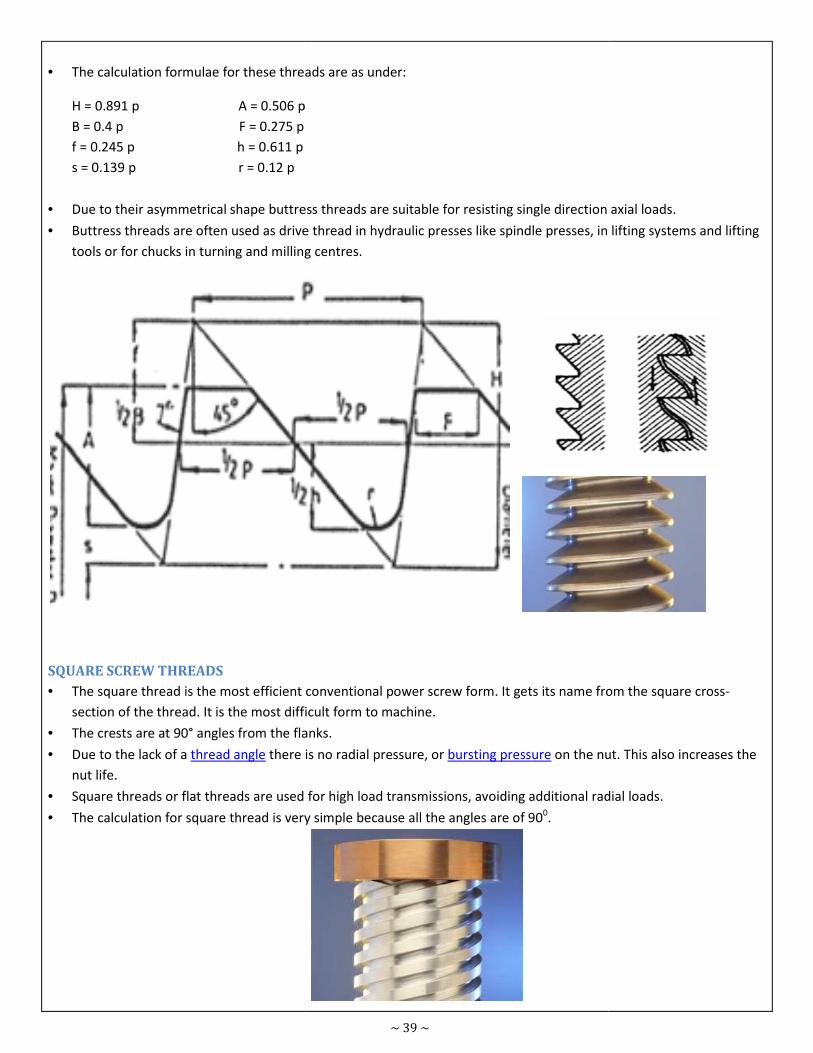
• The calculation formulae for these threads are as under:
H = 0.891 p A = 0.506 p
B = 0.4 p F = 0.275 p
f = 0.245 p h = 0.611 p
s = 0.139 p r = 0.12 p
• Due to their asymmetrical shape buttress threads are
• Buttress threads are often used as drive thread in hydraulic presses like spindle presses, in lifting systems and lifting
tools or for chucks in turning and milling centres.
SQUARE SCREW THREADS
• The square thread is the most efficient conventional power screw form. It gets its name from the square cross
section of the thread. It is the most difficult form to machine.
• The crests are at 90° angles from the flanks.
• Due to the lack of a thread angle there is no radial pressure, or
nut life.
• Square threads or flat threads are used for high load transmissions, avoiding additional radial loads.
• The calculation for square thread is very simple because all the angles are of 90
~ 39 ~
The calculation formulae for these threads are as under:
A = 0.506 p
Due to their asymmetrical shape buttress threads are suitable for resisting single direction axial loads.
Buttress threads are often used as drive thread in hydraulic presses like spindle presses, in lifting systems and lifting
tools or for chucks in turning and milling centres.
The square thread is the most efficient conventional power screw form. It gets its name from the square cross
section of the thread. It is the most difficult form to machine.
The crests are at 90° angles from the flanks.
there is no radial pressure, or bursting pressure on the nut. This also increases the
are used for high load transmissions, avoiding additional radial loads.
The calculation for square thread is very simple because all the angles are of 900.
suitable for resisting single direction axial loads.
Buttress threads are often used as drive thread in hydraulic presses like spindle presses, in lifting systems and lifting
The square thread is the most efficient conventional power screw form. It gets its name from the square cross-
on the nut. This also increases the
are used for high load transmissions, avoiding additional radial loads.
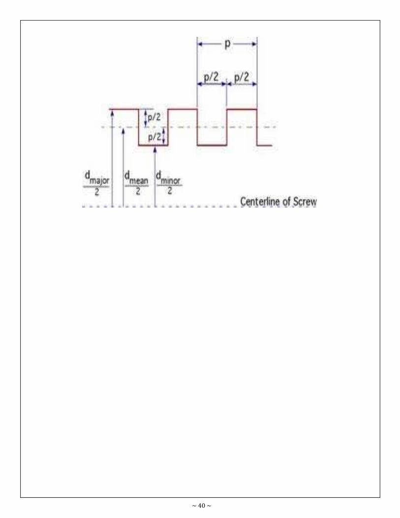
~ 40 ~
~ 41 ~
Fastening & Joining Module
No. 8.03
Prepared
by
Hammad
Mateen
Course Certificate in Engineering Skills Duration 60 - Mins
Teaching Aid
Topic Identify types and applications of spanners
8.3 - IDENTIFY TYPES AND APPLICATIONS OF SPANNERS
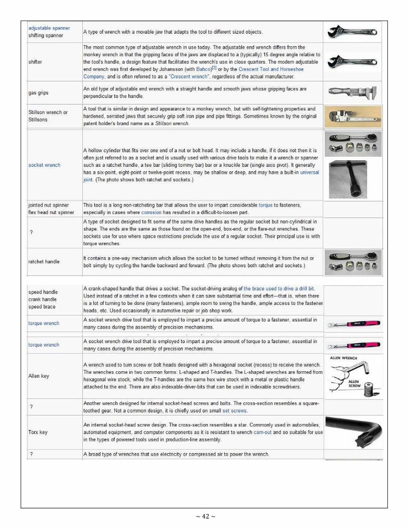
~ 42 ~
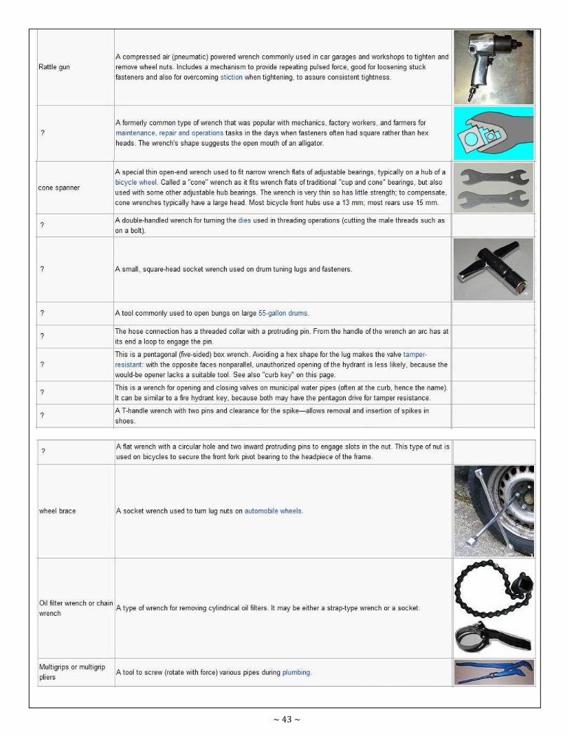
~ 43 ~
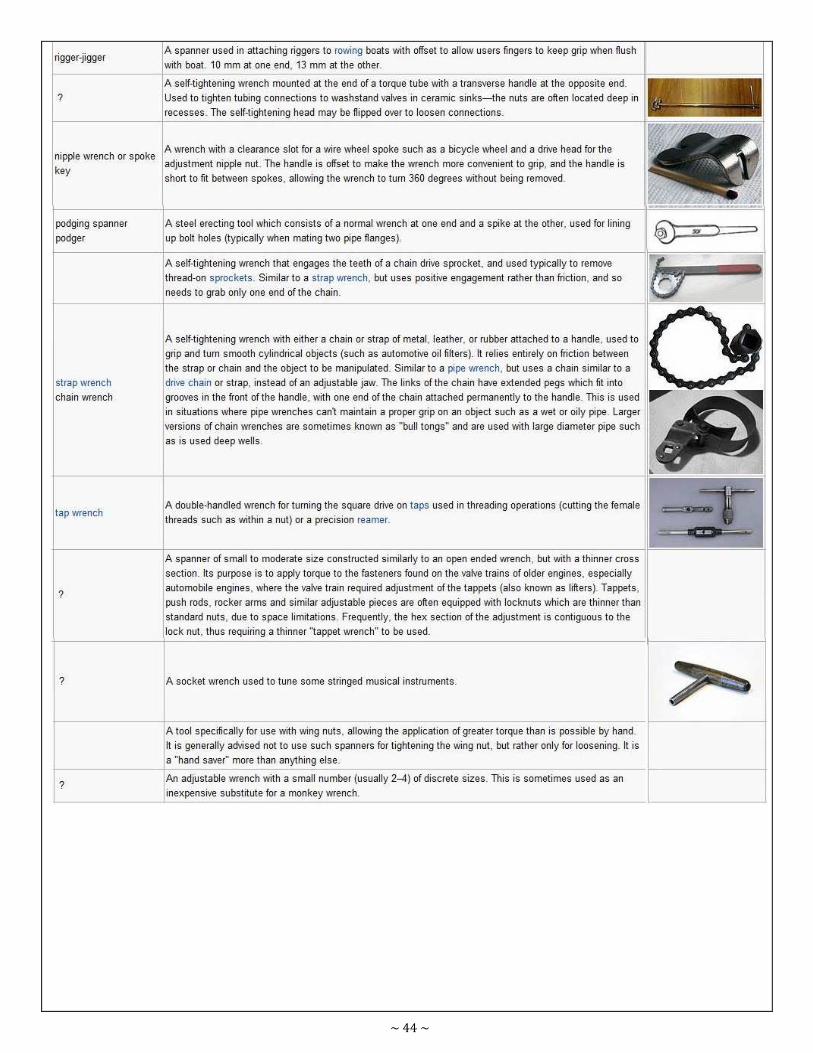
~ 44 ~

~ 45 ~
Fastening & Joining Module
No. 8.04
Prepared
by M.Ramzan
Course Certificate in Engineering Skills Duration 30 - Mins
Teaching Aid
Topic Identify riveted and bolt joints
8.4 - IDENTIFY RIVETED AND BOLT JOINTS
8.4.1 - JOINTS
LAP JOINT
SINGLE & DOUBLE COVER PLATE BUTT JOINT.
RIVET: A rivet is a semi permanent mechanical fastener.
Before being installed, a rivet consists of a smooth cylindrical shaft with a head on one end. The end opposite the
head is called the buck-tail
BOLT: A bolt is a temporary (usually) metal fastener, consisting of a cylindrical body that is threaded, with a larger head
on one end. It can be inserted into an unthreaded hole up to the head, tighten with a nut on the other end.
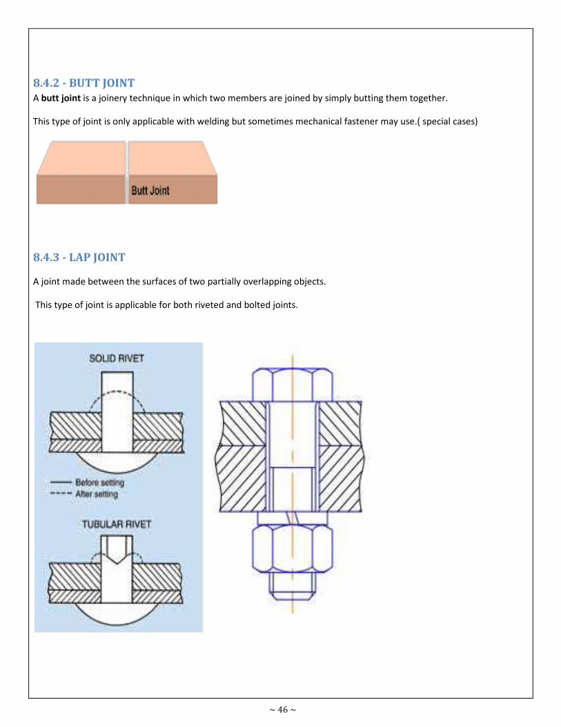
~ 46 ~
8.4.2 - BUTT JOINT
A butt joint is a joinery technique in which two members are joined by simply butting them together.
This type of joint is only applicable with welding but sometimes mechanical fastener may use.( special cases)
8.4.3 - LAP JOINT
A joint made between the surfaces of two partially overlapping objects.
This type of joint is applicable for both riveted and bolted joints.
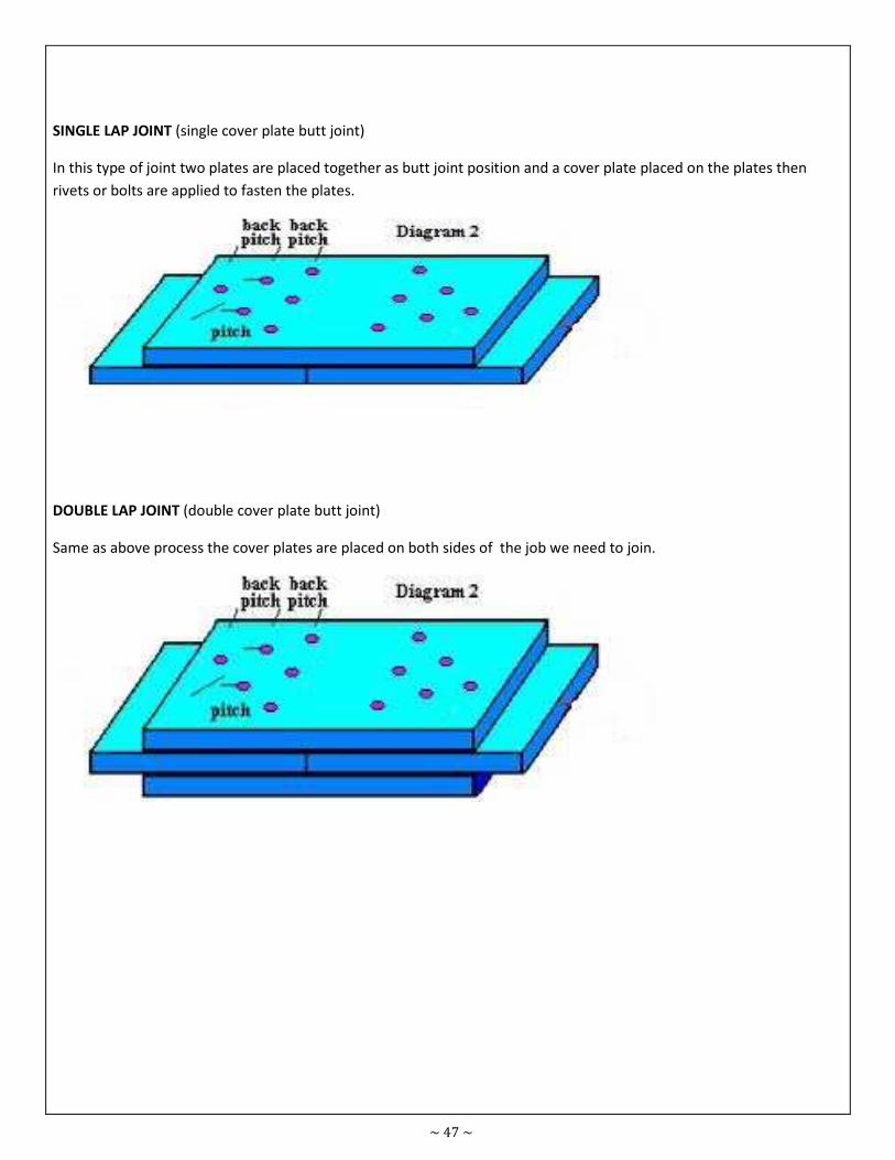
~ 47 ~
SINGLE LAP JOINT (single cover plate butt joint)
In this type of joint two plates are placed together as butt joint position and a cover plate placed on the plates then
rivets or bolts are applied to fasten the plates.
DOUBLE LAP JOINT (double cover plate butt joint)
Same as above process the cover plates are placed on both sides of the job we need to join.
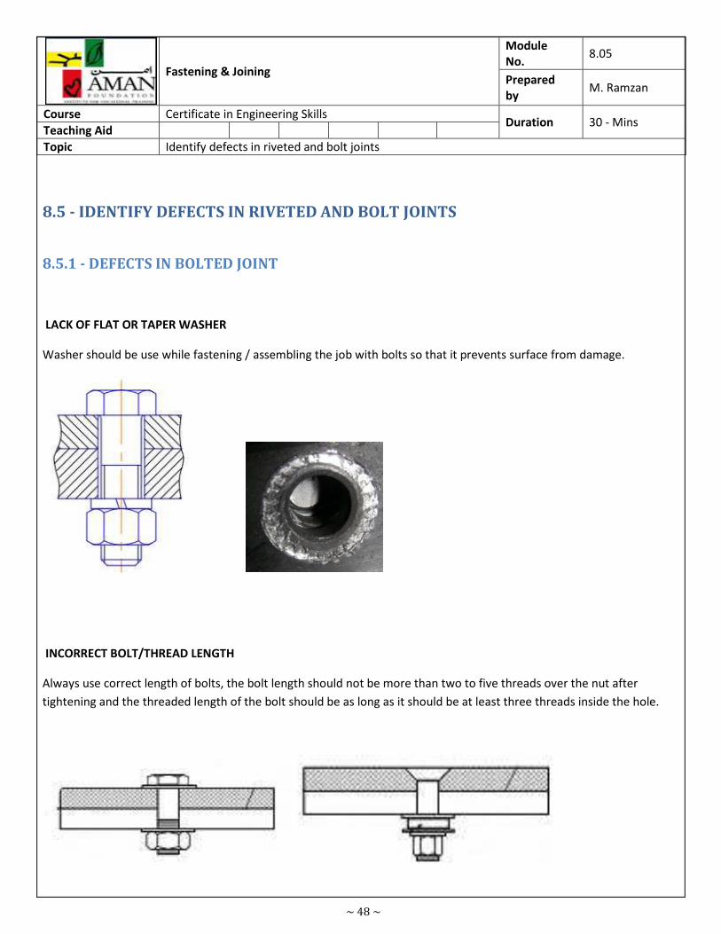
~ 48 ~
Fastening & Joining
Module
No. 8.05
Prepared
by M. Ramzan
Course Certificate in Engineering Skills Duration 30 - Mins
Teaching Aid
Topic Identify defects in riveted and bolt joints
8.5 - IDENTIFY DEFECTS IN RIVETED AND BOLT JOINTS
8.5.1 - DEFECTS IN BOLTED JOINT
LACK OF FLAT OR TAPER WASHER
Washer should be use while fastening / assembling the job with bolts so that it prevents surface from damage.
INCORRECT BOLT/THREAD LENGTH
Always use correct length of bolts, the bolt length should not be more than two to five threads over the nut after
tightening and the threaded length of the bolt should be as long as it should be at least three threads inside the hole.
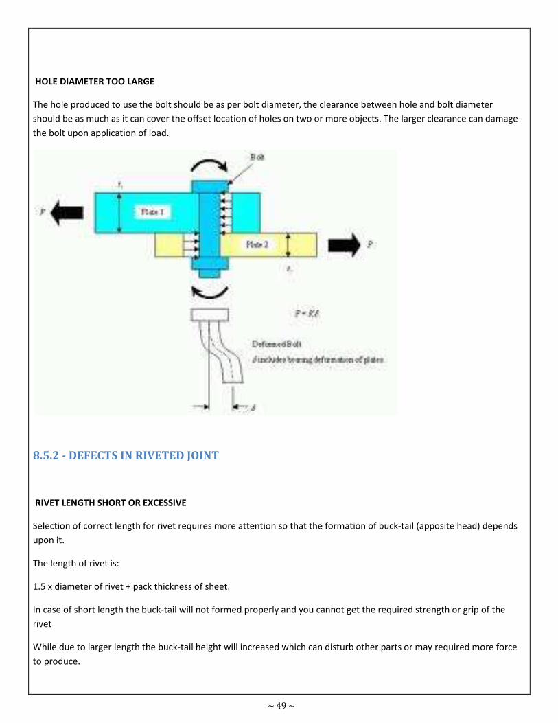
~ 49 ~
HOLE DIAMETER TOO LARGE
The hole produced to use the bolt should be as per bolt diameter, the clearance between hole and bolt diameter
should be as much as it can cover the offset location of holes on two or more objects. The larger clearance can damage
the bolt upon application of load.
8.5.2 - DEFECTS IN RIVETED JOINT
RIVET LENGTH SHORT OR EXCESSIVE
Selection of correct length for rivet requires more attention so that the formation of buck-tail (apposite head) depends
upon it.
The length of rivet is:
1.5 x diameter of rivet + pack thickness of sheet.
In case of short length the buck-tail will not formed properly and you cannot get the required strength or grip of the
rivet
While due to larger length the buck-tail height will increased which can disturb other parts or may required more force
to produce.
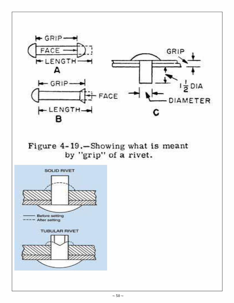
~ 50 ~
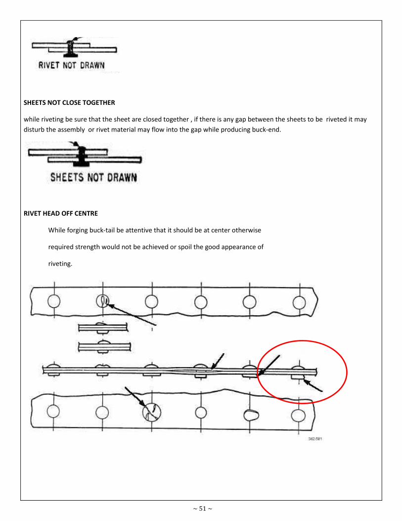
~ 51 ~
SHEETS NOT CLOSE TOGETHER
while riveting be sure that the sheet are closed together , if there is any gap between the sheets to be riveted it may
disturb the assembly or rivet material may flow into the gap while producing buck-end.
RIVET HEAD OFF CENTRE
While forging buck-tail be attentive that it should be at center otherwise
required strength would not be achieved or spoil the good appearance of
riveting.
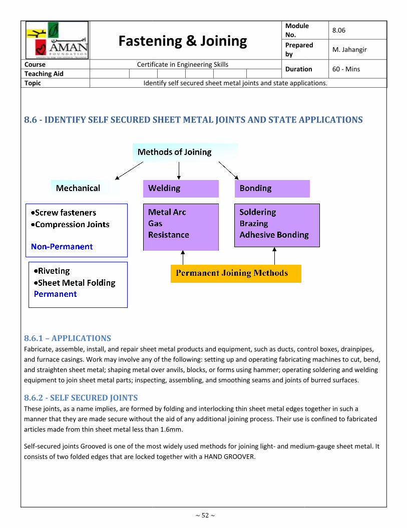
Fastening & Joining
Course Certificate in Engineering Skills
Teaching Aid
Topic Identify self secured sheet metal joints and state applications.
8.6 - IDENTIFY SELF SECURED SHEET META
8.6.1 – APPLICATIONS
Fabricate, assemble, install, and repair sheet metal products and equipment, such as ducts, control boxes, drainpipes,
and furnace casings. Work may involve any of the followin
and straighten sheet metal; shaping metal over anvils, blocks, or forms using hammer; operating soldering and welding
equipment to join sheet metal parts; inspecting, assembling, and smoothing
8.6.2 - SELF SECURED JOINTS
These joints, as a name implies, are formed by folding and interlocking thin sheet metal edges together in such a
manner that they are made secure without the aid of any additional joining pr
articles made from thin sheet metal less than 1.6mm.
Self-secured joints Grooved is one of the most widely used methods for joining light
consists of two folded edges that are locked together with a HAND GROOVER.
~ 52 ~
Fastening & Joining Module
No.
Prepared
by
Certificate in Engineering Skills Duration
Identify self secured sheet metal joints and state applications.
SELF SECURED SHEET METAL JOINTS AND STATE APPLICATIONS
Fabricate, assemble, install, and repair sheet metal products and equipment, such as ducts, control boxes, drainpipes,
and furnace casings. Work may involve any of the following: setting up and operating fabricating machines to cut, bend,
and straighten sheet metal; shaping metal over anvils, blocks, or forms using hammer; operating soldering and welding
equipment to join sheet metal parts; inspecting, assembling, and smoothing seams and joints of burred surfaces.
These joints, as a name implies, are formed by folding and interlocking thin sheet metal edges together in such a
manner that they are made secure without the aid of any additional joining process. Their use is confined to fabricated
articles made from thin sheet metal less than 1.6mm.
secured joints Grooved is one of the most widely used methods for joining light- and medium
ked together with a HAND GROOVER.
Module 8.06
Prepared M. Jahangir
Duration 60 - Mins
Identify self secured sheet metal joints and state applications.
L JOINTS AND STATE APPLICATIONS
Fabricate, assemble, install, and repair sheet metal products and equipment, such as ducts, control boxes, drainpipes,
g: setting up and operating fabricating machines to cut, bend,
and straighten sheet metal; shaping metal over anvils, blocks, or forms using hammer; operating soldering and welding
seams and joints of burred surfaces.
These joints, as a name implies, are formed by folding and interlocking thin sheet metal edges together in such a
ocess. Their use is confined to fabricated
and medium-gauge sheet metal. It
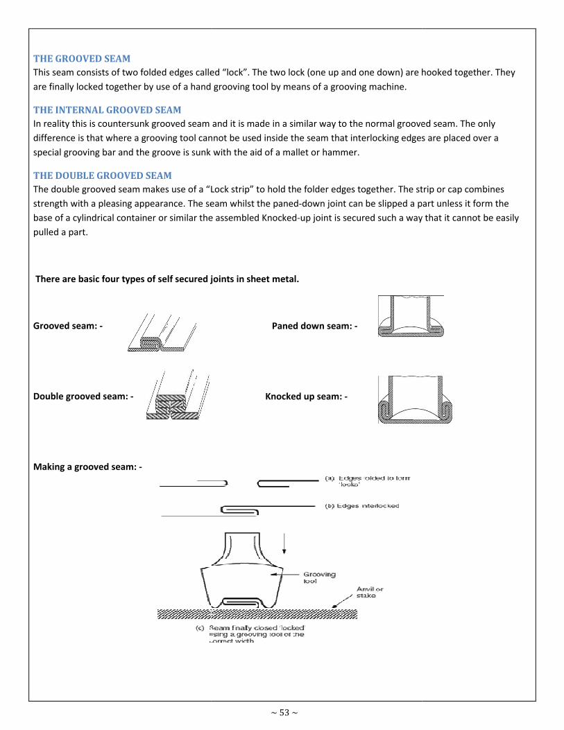
THE GROOVED SEAM
This seam consists of two folded edges called “lock”. The two lock (one up and one down) are hooked together. They
are finally locked together by use of a hand grooving tool by means of a grooving machi
THE INTERNAL GROOVED SEAM
In reality this is countersunk grooved seam and it is made in a similar way to the normal grooved seam. The only
difference is that where a grooving tool cannot be used inside the seam that interlocking edges are placed over
special grooving bar and the groove is sunk with the aid of a mallet or hammer.
THE DOUBLE GROOVED SEAM
The double grooved seam makes use of a “Lock strip” to hold the folder edges together. The strip or cap combines
strength with a pleasing appearance. The seam whilst the paned
base of a cylindrical container or similar the assembled Knocked
pulled a part.
There are basic four types of self secured joints in sheet metal.
Grooved seam: -
Double grooved seam: -
Making a grooved seam: -
~ 53 ~
This seam consists of two folded edges called “lock”. The two lock (one up and one down) are hooked together. They
are finally locked together by use of a hand grooving tool by means of a grooving machine.
In reality this is countersunk grooved seam and it is made in a similar way to the normal grooved seam. The only
difference is that where a grooving tool cannot be used inside the seam that interlocking edges are placed over
special grooving bar and the groove is sunk with the aid of a mallet or hammer.
The double grooved seam makes use of a “Lock strip” to hold the folder edges together. The strip or cap combines
The seam whilst the paned-down joint can be slipped a part unless it form the
base of a cylindrical container or similar the assembled Knocked-up joint is secured such a way that it cannot be easily
There are basic four types of self secured joints in sheet metal.
Paned down seam: -
Knocked up seam: -
This seam consists of two folded edges called “lock”. The two lock (one up and one down) are hooked together. They
In reality this is countersunk grooved seam and it is made in a similar way to the normal grooved seam. The only
difference is that where a grooving tool cannot be used inside the seam that interlocking edges are placed over a
The double grooved seam makes use of a “Lock strip” to hold the folder edges together. The strip or cap combines
down joint can be slipped a part unless it form the
up joint is secured such a way that it cannot be easily
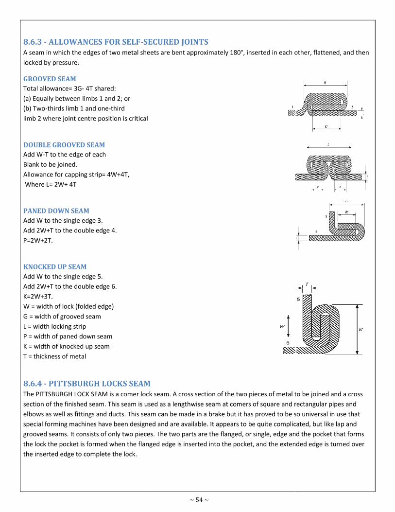
8.6.3 - ALLOWANCES FOR SELF-SECURED JOINTS
A seam in which the edges of two metal sheets are bent approximately 180°, inserted in each other, flattened, and then
locked by pressure.
GROOVED SEAM
Total allowance= 3G- 4T shared:
(a) Equally between limbs 1 and 2; or
(b) Two-thirds limb 1 and one-third
limb 2 where joint centre position is critical
DOUBLE GROOVED SEAM
Add W-T to the edge of each
Blank to be joined.
Allowance for capping strip= 4W+4T,
Where L= 2W+ 4T
PANED DOWN SEAM
Add W to the single edge 3.
Add 2W+T to the double edge 4.
P=2W+2T.
KNOCKED UP SEAM
Add W to the single edge 5.
Add 2W+T to the double edge 6.
K=2W+3T.
W = width of lock (folded edge)
G = width of grooved seam
L = width locking strip
P = width of paned down seam
K = width of knocked up seam
T = thickness of metal
8.6.4 - PITTSBURGH LOCKS SEAM
The PITTSBURGH LOCK SEAM is a comer lock seam. A cross section of the two pieces of metal to be joined and a cross
section of the finished seam. This seam is used as a lengthwise seam
elbows as well as fittings and ducts. This seam can be made in a brake but it has proved to be so universal in use that
special forming machines have been designed and are available. It appears to be quite comp
grooved seams. It consists of only two pieces. The two parts are the flanged, or single, edge and the pocket that forms
the lock the pocket is formed when the flanged edge is inserted into the pocket, and the extended edge is turn
the inserted edge to complete the lock.
~ 54 ~
SECURED JOINTS
A seam in which the edges of two metal sheets are bent approximately 180°, inserted in each other, flattened, and then
limb 2 where joint centre position is critical
PITTSBURGH LOCKS SEAM
The PITTSBURGH LOCK SEAM is a comer lock seam. A cross section of the two pieces of metal to be joined and a cross
section of the finished seam. This seam is used as a lengthwise seam at comers of square and rectangular pipes and
elbows as well as fittings and ducts. This seam can be made in a brake but it has proved to be so universal in use that
special forming machines have been designed and are available. It appears to be quite complicated, but like lap and
grooved seams. It consists of only two pieces. The two parts are the flanged, or single, edge and the pocket that forms
the lock the pocket is formed when the flanged edge is inserted into the pocket, and the extended edge is turn
A seam in which the edges of two metal sheets are bent approximately 180°, inserted in each other, flattened, and then
The PITTSBURGH LOCK SEAM is a comer lock seam. A cross section of the two pieces of metal to be joined and a cross
at comers of square and rectangular pipes and
elbows as well as fittings and ducts. This seam can be made in a brake but it has proved to be so universal in use that
licated, but like lap and
grooved seams. It consists of only two pieces. The two parts are the flanged, or single, edge and the pocket that forms
the lock the pocket is formed when the flanged edge is inserted into the pocket, and the extended edge is turned over
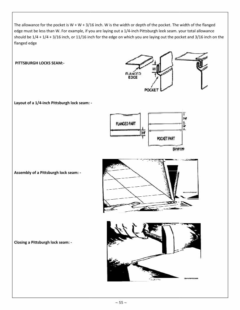
The allowance for the pocket is W + W + 3/16 inch. W is the width or depth of the pocket. The width of the flanged
edge must be less than W. For example, if you are laying out a 1/4
should be 1/4 + 1/4 + 3/16 inch, or 11/16 inch for the edge on which you are laying out the pocket and 3/16 inch on the
flanged edge
PITTSBURGH LOCKS SEAM:-
Layout of a 1/4-inch Pittsburgh lock seam:
Assembly of a Pittsburgh lock seam: -
Closing a Pittsburgh lock seam: -
~ 55 ~
The allowance for the pocket is W + W + 3/16 inch. W is the width or depth of the pocket. The width of the flanged
edge must be less than W. For example, if you are laying out a 1/4-inch Pittsburgh leek seam. your total allowance
should be 1/4 + 1/4 + 3/16 inch, or 11/16 inch for the edge on which you are laying out the pocket and 3/16 inch on the
inch Pittsburgh lock seam: -
The allowance for the pocket is W + W + 3/16 inch. W is the width or depth of the pocket. The width of the flanged
m. your total allowance
should be 1/4 + 1/4 + 3/16 inch, or 11/16 inch for the edge on which you are laying out the pocket and 3/16 inch on the
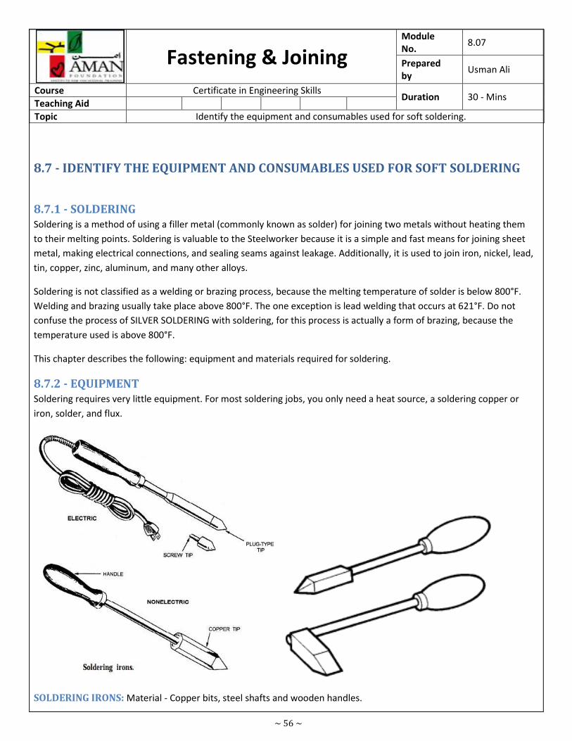
~ 56 ~
Fastening & Joining Module
No. 8.07
Prepared
by Usman Ali
Course Certificate in Engineering Skills Duration 30 - Mins
Teaching Aid
Topic Identify the equipment and consumables used for soft soldering.
8.7 - IDENTIFY THE EQUIPMENT AND CONSUMABLES USED FOR SOFT SOLDERING
8.7.1 - SOLDERING
Soldering is a method of using a filler metal (commonly known as solder) for joining two metals without heating them
to their melting points. Soldering is valuable to the Steelworker because it is a simple and fast means for joining sheet
metal, making electrical connections, and sealing seams against leakage. Additionally, it is used to join iron, nickel, lead,
tin, copper, zinc, aluminum, and many other alloys.
Soldering is not classified as a welding or brazing process, because the melting temperature of solder is below 800°F.
Welding and brazing usually take place above 800°F. The one exception is lead welding that occurs at 621°F. Do not
confuse the process of SILVER SOLDERING with soldering, for this process is actually a form of brazing, because the
temperature used is above 800°F.
This chapter describes the following: equipment and materials required for soldering.
8.7.2 - EQUIPMENT
Soldering requires very little equipment. For most soldering jobs, you only need a heat source, a soldering copper or
iron, solder, and flux.
SOLDERING IRONS: Material - Copper bits, steel shafts and wooden handles.
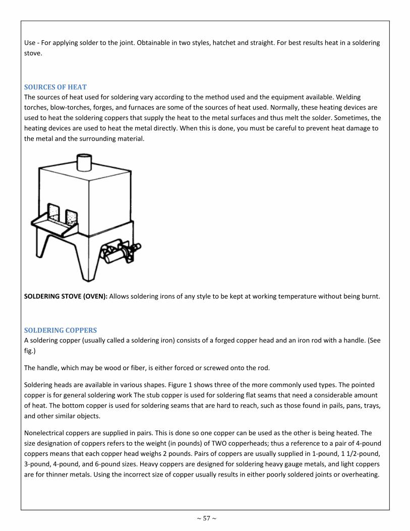
~ 57 ~
Use - For applying solder to the joint. Obtainable in two styles, hatchet and straight. For best results heat in a soldering
stove.
SOURCES OF HEAT
The sources of heat used for soldering vary according to the method used and the equipment available. Welding
torches, blow-torches, forges, and furnaces are some of the sources of heat used. Normally, these heating devices are
used to heat the soldering coppers that supply the heat to the metal surfaces and thus melt the solder. Sometimes, the
heating devices are used to heat the metal directly. When this is done, you must be careful to prevent heat damage to
the metal and the surrounding material.
SOLDERING STOVE (OVEN): Allows soldering irons of any style to be kept at working temperature without being burnt.
SOLDERING COPPERS
A soldering copper (usually called a soldering iron) consists of a forged copper head and an iron rod with a handle. (See
fig.)
The handle, which may be wood or fiber, is either forced or screwed onto the rod.
Soldering heads are available in various shapes. Figure 1 shows three of the more commonly used types. The pointed
copper is for general soldering work The stub copper is used for soldering flat seams that need a considerable amount
of heat. The bottom copper is used for soldering seams that are hard to reach, such as those found in pails, pans, trays,
and other similar objects.
Nonelectrical coppers are supplied in pairs. This is done so one copper can be used as the other is being heated. The
size designation of coppers refers to the weight (in pounds) of TWO copperheads; thus a reference to a pair of 4-pound
coppers means that each copper head weighs 2 pounds. Pairs of coppers are usually supplied in 1-pound, 1 1/2-pound,
3-pound, 4-pound, and 6-pound sizes. Heavy coppers are designed for soldering heavy gauge metals, and light coppers
are for thinner metals. Using the incorrect size of copper usually results in either poorly soldered joints or overheating.
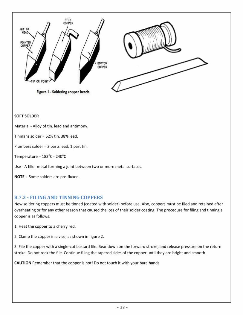
~ 58 ~
SOFT SOLDER
Material - Alloy of tin. lead and antimony.
Tinmans solder = 62% tin, 38% lead.
Plumbers solder = 2 parts lead, 1 part tin.
Temperature = 183oC - 240oC
Use - A filler metal forming a joint between two or more metal surfaces.
NOTE - Some solders are pre-fluxed.
8.7.3 - FILING AND TINNING COPPERS
New soldering coppers must be tinned (coated with solder) before use. Also, coppers must be filed and retained after
overheating or for any other reason that caused the loss of their solder coating. The procedure for filing and tinning a
copper is as follows:
1. Heat the copper to a cherry red.
2. Clamp the copper in a vise, as shown in figure 2.
3. File the copper with a single-cut bastard file. Bear down on the forward stroke, and release pressure on the return
stroke. Do not rock the file. Continue filing the tapered sides of the copper until they are bright and smooth.
CAUTION Remember that the copper is hot! Do not touch it with your bare hands.
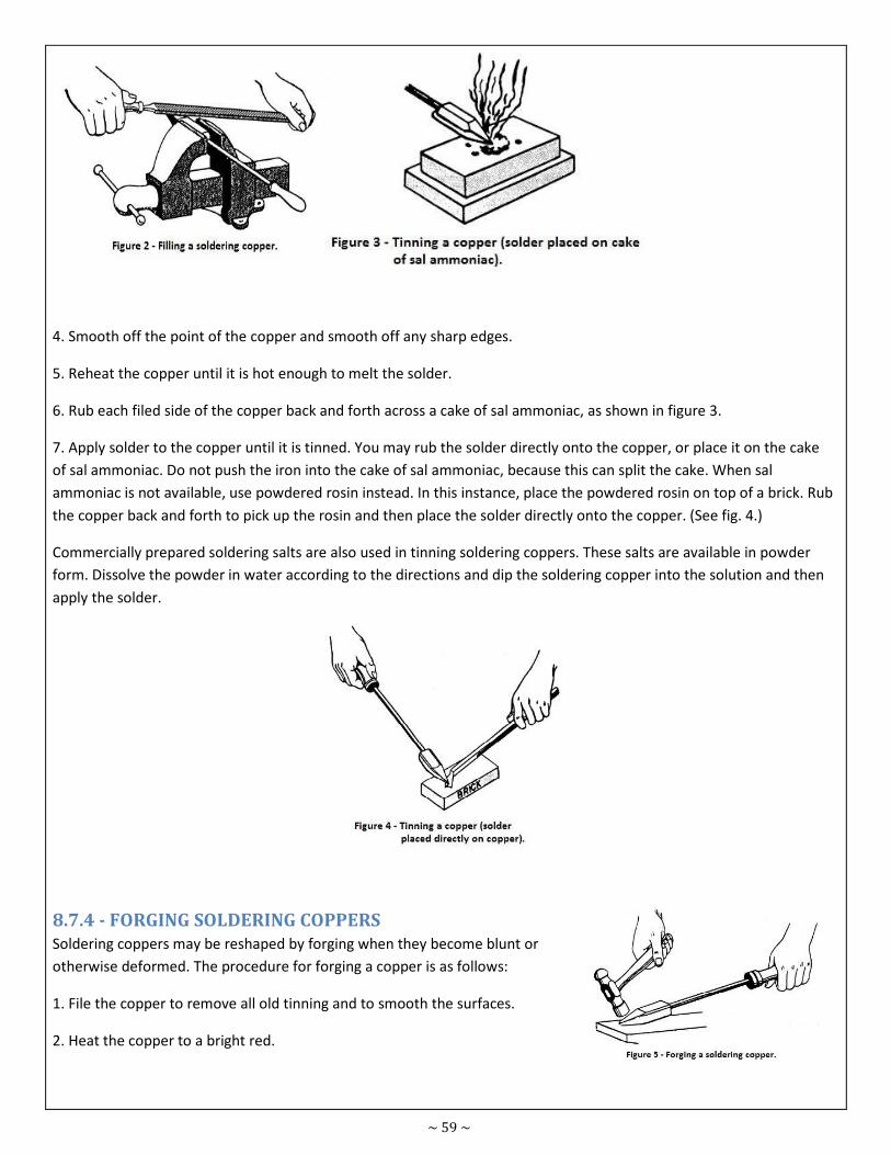
~ 59 ~
4. Smooth off the point of the copper and smooth off any sharp edges.
5. Reheat the copper until it is hot enough to melt the solder.
6. Rub each filed side of the copper back and forth across a cake of sal ammoniac, as shown in figure 3.
7. Apply solder to the copper until it is tinned. You may rub the solder directly onto the copper, or place it on the cake
of sal ammoniac. Do not push the iron into the cake of sal ammoniac, because this can split the cake. When sal
ammoniac is not available, use powdered rosin instead. In this instance, place the powdered rosin on top of a brick. Rub
the copper back and forth to pick up the rosin and then place the solder directly onto the copper. (See fig. 4.)
Commercially prepared soldering salts are also used in tinning soldering coppers. These salts are available in powder
form. Dissolve the powder in water according to the directions and dip the soldering copper into the solution and then
apply the solder.
8.7.4 - FORGING SOLDERING COPPERS
Soldering coppers may be reshaped by forging when they become blunt or
otherwise deformed. The procedure for forging a copper is as follows:
1. File the copper to remove all old tinning and to smooth the surfaces.
2. Heat the copper to a bright red.
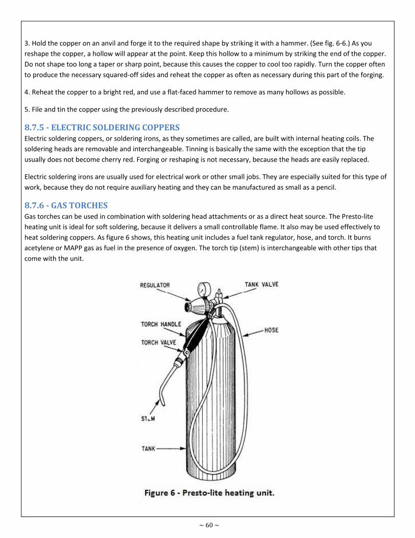
~ 60 ~
3. Hold the copper on an anvil and forge it to the required shape by striking it with a hammer. (See fig. 6-6.) As you
reshape the copper, a hollow will appear at the point. Keep this hollow to a minimum by striking the end of the copper.
Do not shape too long a taper or sharp point, because this causes the copper to cool too rapidly. Turn the copper often
to produce the necessary squared-off sides and reheat the copper as often as necessary during this part of the forging.
4. Reheat the copper to a bright red, and use a flat-faced hammer to remove as many hollows as possible.
5. File and tin the copper using the previously described procedure.
8.7.5 - ELECTRIC SOLDERING COPPERS
Electric soldering coppers, or soldering irons, as they sometimes are called, are built with internal heating coils. The
soldering heads are removable and interchangeable. Tinning is basically the same with the exception that the tip
usually does not become cherry red. Forging or reshaping is not necessary, because the heads are easily replaced.
Electric soldering irons are usually used for electrical work or other small jobs. They are especially suited for this type of
work, because they do not require auxiliary heating and they can be manufactured as small as a pencil.
8.7.6 - GAS TORCHES
Gas torches can be used in combination with soldering head attachments or as a direct heat source. The Presto-lite
heating unit is ideal for soft soldering, because it delivers a small controllable flame. It also may be used effectively to
heat soldering coppers. As figure 6 shows, this heating unit includes a fuel tank regulator, hose, and torch. It burns
acetylene or MAPP gas as fuel in the presence of oxygen. The torch tip (stem) is interchangeable with other tips that
come with the unit.
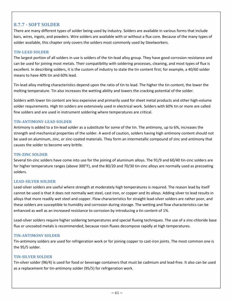
~ 61 ~
8.7.7 - SOFT SOLDER
There are many different types of solder being used by industry. Solders are available in various forms that include
bars, wires, ingots, and powders. Wire solders are available with or without a flux core. Because of the many types of
solder available, this chapter only covers the solders most commonly used by Steelworkers.
TIN-LEAD SOLDER
The largest portion of all solders in use is solders of the tin-lead alloy group. They have good corrosion resistance and
can be used for joining most metals. Their compatibility with soldering processes, cleaning, and most types of flux is
excellent. In describing solders, it is the custom of industry to state the tin content first; for example, a 40/60 solder
means to have 40% tin and 60% lead.
Tin-lead alloy melting characteristics depend upon the ratio of tin to lead. The higher the tin content, the lower the
melting temperature. Tin also increases the wetting ability and lowers the cracking potential of the solder.
Solders with lower tin content are less expensive and primarily used for sheet metal products and other high-volume
solder requirements. High tin solders are extensively used in electrical work. Solders with 60% tin or more are called
fine solders and are used in instrument soldering where temperatures are critical.
TIN-ANTIMONY-LEAD SOLDER
Antimony is added to a tin-lead solder as a substitute for some of the tin. The antimony, up to 6%, increases the
strength and mechanical properties of the solder. A word of caution, solders having high antimony content should not
be used on aluminum, zinc, or zinc-coated materials. They form an intermetallic compound of zinc and antimony that
causes the solder to become very brittle.
TIN-ZINC SOLDER
Several tin-zinc solders have come into use for the joining of aluminum alloys. The 91/9 and 60/40 tin-zinc solders are
for higher temperature ranges (above 300°F), and the 80/20 and 70/30 tin-zinc alloys are normally used as precoating
solders.
LEAD-SILVER SOLDER
Lead-silver solders are useful where strength at moderately high temperatures is required. The reason lead by itself
cannot be used is that it does not normally wet steel, cast iron, or copper and its alloys. Adding silver to lead results in
alloys that more readily wet steel and copper. Flow characteristics for straight lead-silver solders are rather poor, and
these solders are susceptible to humidity and corrosion during storage. The wetting and flow characteristics can be
enhanced as well as an increased resistance to corrosion by introducing a tin content of 1%.
Lead-silver solders require higher soldering temperatures and special fluxing techniques. The use of a zinc-chloride base
flux or uncoated metals is recommended, because rosin fluxes decompose rapidly at high temperatures.
TIN-ANTIMONY SOLDER
Tin-antimony solders are used for refrigeration work or for joining copper to cast-iron joints. The most common one is
the 95/5 solder.
TIN-SILVER SOLDER
Tin-silver solder (96/4) is used for food or beverage containers that must be cadmium and lead-free. It also can be used
as a replacement for tin-antimony solder (95/5) for refrigeration work.
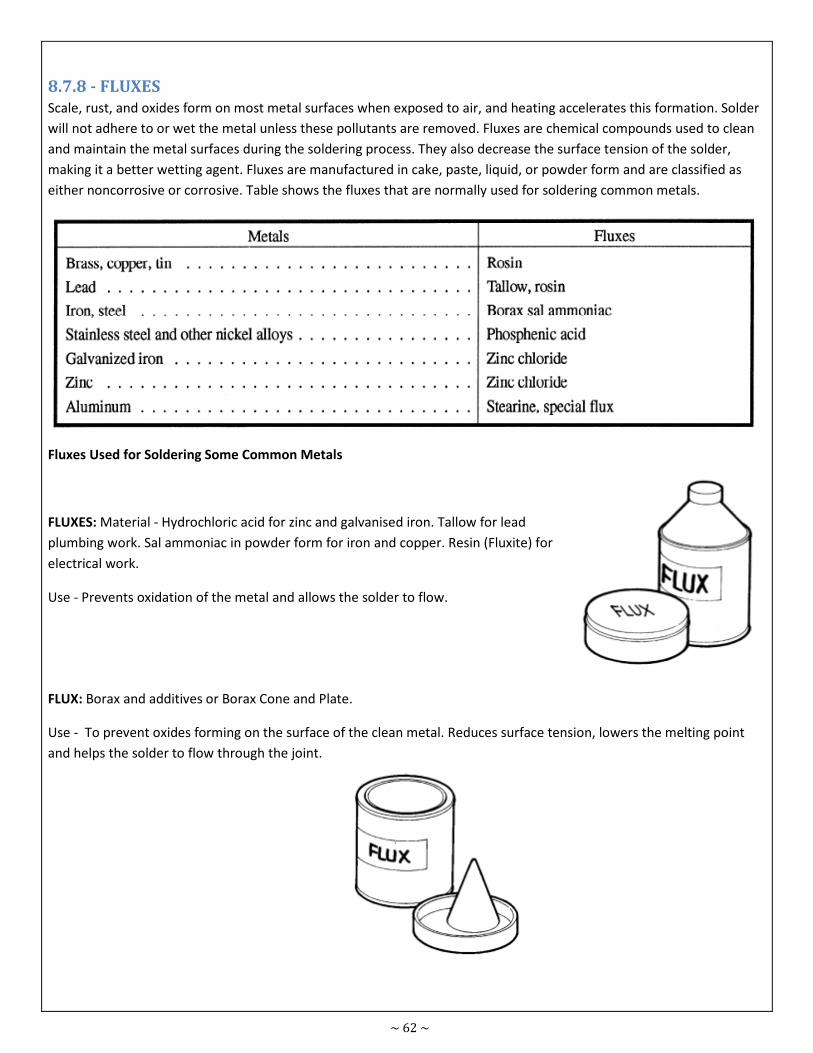
~ 62 ~
8.7.8 - FLUXES
Scale, rust, and oxides form on most metal surfaces when exposed to air, and heating accelerates this formation. Solder
will not adhere to or wet the metal unless these pollutants are removed. Fluxes are chemical compounds used to clean
and maintain the metal surfaces during the soldering process. They also decrease the surface tension of the solder,
making it a better wetting agent. Fluxes are manufactured in cake, paste, liquid, or powder form and are classified as
either noncorrosive or corrosive. Table shows the fluxes that are normally used for soldering common metals.
Fluxes Used for Soldering Some Common Metals
FLUXES: Material - Hydrochloric acid for zinc and galvanised iron. Tallow for lead
plumbing work. Sal ammoniac in powder form for iron and copper. Resin (Fluxite) for
electrical work.
Use - Prevents oxidation of the metal and allows the solder to flow.
FLUX: Borax and additives or Borax Cone and Plate.
Use - To prevent oxides forming on the surface of the clean metal. Reduces surface tension, lowers the melting point
and helps the solder to flow through the joint.
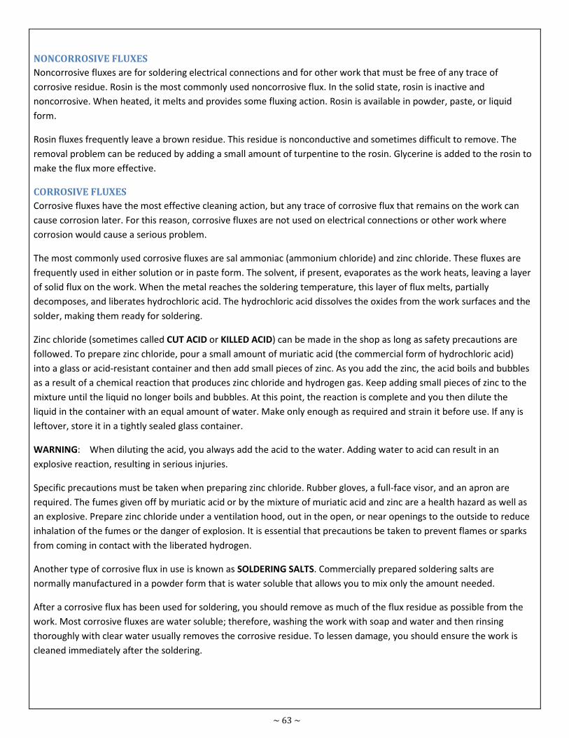
~ 63 ~
NONCORROSIVE FLUXES
Noncorrosive fluxes are for soldering electrical connections and for other work that must be free of any trace of
corrosive residue. Rosin is the most commonly used noncorrosive flux. In the solid state, rosin is inactive and
noncorrosive. When heated, it melts and provides some fluxing action. Rosin is available in powder, paste, or liquid
form.
Rosin fluxes frequently leave a brown residue. This residue is nonconductive and sometimes difficult to remove. The
removal problem can be reduced by adding a small amount of turpentine to the rosin. Glycerine is added to the rosin to
make the flux more effective.
CORROSIVE FLUXES
Corrosive fluxes have the most effective cleaning action, but any trace of corrosive flux that remains on the work can
cause corrosion later. For this reason, corrosive fluxes are not used on electrical connections or other work where
corrosion would cause a serious problem.
The most commonly used corrosive fluxes are sal ammoniac (ammonium chloride) and zinc chloride. These fluxes are
frequently used in either solution or in paste form. The solvent, if present, evaporates as the work heats, leaving a layer
of solid flux on the work. When the metal reaches the soldering temperature, this layer of flux melts, partially
decomposes, and liberates hydrochloric acid. The hydrochloric acid dissolves the oxides from the work surfaces and the
solder, making them ready for soldering.
Zinc chloride (sometimes called CUT ACID or KILLED ACID) can be made in the shop as long as safety precautions are
followed. To prepare zinc chloride, pour a small amount of muriatic acid (the commercial form of hydrochloric acid)
into a glass or acid-resistant container and then add small pieces of zinc. As you add the zinc, the acid boils and bubbles
as a result of a chemical reaction that produces zinc chloride and hydrogen gas. Keep adding small pieces of zinc to the
mixture until the liquid no longer boils and bubbles. At this point, the reaction is complete and you then dilute the
liquid in the container with an equal amount of water. Make only enough as required and strain it before use. If any is
leftover, store it in a tightly sealed glass container.
WARNING: When diluting the acid, you always add the acid to the water. Adding water to acid can result in an
explosive reaction, resulting in serious injuries.
Specific precautions must be taken when preparing zinc chloride. Rubber gloves, a full-face visor, and an apron are
required. The fumes given off by muriatic acid or by the mixture of muriatic acid and zinc are a health hazard as well as
an explosive. Prepare zinc chloride under a ventilation hood, out in the open, or near openings to the outside to reduce
inhalation of the fumes or the danger of explosion. It is essential that precautions be taken to prevent flames or sparks
from coming in contact with the liberated hydrogen.
Another type of corrosive flux in use is known as SOLDERING SALTS. Commercially prepared soldering salts are
normally manufactured in a powder form that is water soluble that allows you to mix only the amount needed.
After a corrosive flux has been used for soldering, you should remove as much of the flux residue as possible from the
work. Most corrosive fluxes are water soluble; therefore, washing the work with soap and water and then rinsing
thoroughly with clear water usually removes the corrosive residue. To lessen damage, you should ensure the work is
cleaned immediately after the soldering.
~ 64 ~
Fastening & Joining Module
No. 8.08
Prepared
by Usman Ali
Course Certificate in Engineering Skills Duration 30 - Mins
Teaching Aid
Topic Basic principles of soft soldering.
8.8 – BASIC PRINCIPLES OF SOFT SOLDERING
Soldering is one of the oldest methods for bonding metal joints. The basic principles of soldering must be recognized in
order to achieve strong and effective bonds, along with proper tools and solder type.
Soft soldering is a process for joining metals together using fairly low melting point filler metals which have the ability
to flow into gaps between joint members by capillary action. In IS0 (International Organization for Standardization)
standards, a soft solder is defined as
“A metallic filler material which is used to join metallic parts and which has a melting temperature (liquidus) lower than
that of the parts to be joined and, usually, lower than 450°C and which wets the parent metals.”
“Brazing”, “hard soldering” and “silver soldering” are terms used for similar capillary joining processes taking place at
higher temperatures with filler metals based on aluminium, copper, nickel, zinc and the precious metals. These
processes are outside the scope of this handbook.
8.8.1 - HEAT AND TIME
The amount of heat, and the time for which it is applied, are the basic principles of soldering. Heat and time variables
are dependent on the thermal properties and mass of the metal surfaces to be joined.
8.8.2 - WETTING
Wetting is the solvent reaction that occurs when melted solder meets and blends with the metal being soldered. Rosin
flux is the chemical substance added to solder, which helps facilitate wetting.
8.8.3 - SOLDER FLOW
Solder is designed to flow when melted. Good solder flow is essential to joints, as the molten solder must penetrate
gaps in metal and wire parts to form a strong joint. Flow is achieved by proper heat, time and technique.
~ 65 ~
8.8.4 - SURFACE CONDITION
All surfaces to be soldered must be free of oils, grease, dirt, debris and visible oxidation. Surfaces should be cleaned
with a fast evaporating, nonflammable solvent when possible, or abraded with emery cloth.
8.8.5 - THERMAL MASS
Thermal mass is the metal's ability to transfer heat. The larger the mass, the more heat it will require to generate
sufficient temperature to melt solder. Higher wattage soldering tools are required to work on surfaces with large
thermal masses.
8.8.6 - TOOLS
Adjustable solder stations allow variable temperatures to the soldering iron. A selection of iron tips and solder is
needed for work on different surface and thermal mass types. Small holding clamps and vices assist in holding parts
together.
8.8.7 - SOLDERING TECHNIQUES
The two soldering methods most often used are soldering with coppers or torch soldering. The considerations that
apply to these methods of soldering are as follows:
Clean all surfaces of oxides, dirt, grease, and other foreign matter.
Use the proper flux for the particular job. Some work requires the use of corrosive fluxes, while other work requires the
use of noncorrosive fluxes. Remember, the melting point of the flux must be BELOW the melting point of the solder you
are going to use.
Heat the surfaces just enough to melt the solder. Solder does not stick to unheated surfaces; however, you should be
very careful not to overheat the solder, the soldering coppers, or the surfaces to be joined. Heating solder above the
work temperature increases the rate of oxidation and changes the proportions of tin and lead.
After making a soldered joint, you should remove as much of the corrosive flux as possible.
~ 66 ~
Fastening & Joining Module
No. 8.09
Prepared
by M. Younus
Course Certificate in Engineering Skills Duration 30 - Mins
Teaching Aid
Topic Identify the equipment and consumables used for brazing.
8.9 - IDENTIFY THE EQUIPMENT AND CONSUMABLES USED FOR BRAZING
8.9.1 - BRAZING
Brazing is the process of joining metal by heating the base metal to a temperature above 800°F and adding a
nonferrous filler metal that melts below the base metal. Brazing should not be confused with braze welding, even
though these two terms are often interchanged. In brazing, the filler metal is drawn into the joint by capillary action
and in braze welding it is distributed by tinning. Brazing is sometimes called hard soldering or silver soldering because
the filler metals are either hard solders or silver-based alloys. Both processes require distinct joint designs.
ADVANTAGES AND DISADVANTAGES
Brazing has many advantages over other metal-joining techniques, such as welding. Since brazing does not melt the
base metal of the joint, it allows much tighter control over tolerances and produces a clean joint without the need for
secondary finishing. Additionally, dissimilar metals and non-metals (i.e. metalized ceramics) can be brazed. In general,
brazing also produces less thermal distortion than welding due to the uniform heating of a brazed piece. Complex and
multi-part assemblies can be brazed cost-effectively. Another advantage is that the brazing can be coated or clad for
protective purposes. Finally, brazing is easily adapted to mass production and it is easy to automate because the
individual process parameters are less sensitive to variation.
One of the main disadvantages is: the lack of joint strength as compared to a welded joint due to the softer filler metals
used.[1][dubious – discuss] The strength of the brazed joint is likely to be less than that of the base metal(s) but greater
than the filler metal.[citation needed] Another disadvantage is that brazed joints can be damaged under high service
temperatures.[1] Brazed joints require a high degree of base-metal cleanliness when done in an industrial setting. Some
brazing applications require the use of adequate fluxing agents to control cleanliness. The joint color is often different
than that of the base metal, creating an aesthetic disadvantage.
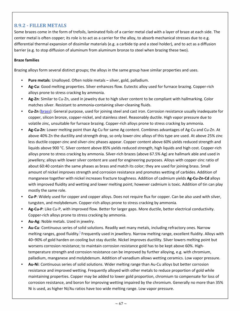
~ 67 ~
8.9.2 - FILLER METALS
Some brazes come in the form of trefoils, laminated foils of a carrier metal clad with a layer of braze at each side. The
center metal is often copper; its role is to act as a carrier for the alloy, to absorb mechanical stresses due to e.g.
differential thermal expansion of dissimilar materials (e.g. a carbide tip and a steel holder), and to act as a diffusion
barrier (e.g. to stop diffusion of aluminum from aluminum bronze to steel when brazing these two).
Braze families
Brazing alloys form several distinct groups; the alloys in the same group have similar properties and uses.
• Pure metals: Unalloyed. Often noble metals – silver, gold, palladium.
• Ag-Cu: Good melting properties. Silver enhances flow. Eutectic alloy used for furnace brazing. Copper-rich
alloys prone to stress cracking by ammonia.
• Ag-Zn: Similar to Cu-Zn, used in jewelry due to high silver content to be compliant with hallmarking. Color
matches silver. Resistant to ammonia-containing silver-cleaning fluids.
• Cu-Zn (brass): General purpose, used for joining steel and cast iron. Corrosion resistance usually inadequate for
copper, silicon bronze, copper-nickel, and stainless steel. Reasonably ductile. High vapor pressure due to
volatile zinc, unsuitable for furnace brazing. Copper-rich alloys prone to stress cracking by ammonia.
• Ag-Cu-Zn: Lower melting point than Ag-Cu for same Ag content. Combines advantages of Ag-Cu and Cu-Zn. At
above 40% Zn the ductility and strength drop, so only lower-zinc alloys of this type are used. At above 25% zinc
less ductile copper-zinc and silver-zinc phases appear. Copper content above 60% yields reduced strength and
liquids above 900 °C. Silver content above 85% yields reduced strength, high liquids and high cost. Copper-rich
alloys prone to stress cracking by ammonia. Silver-rich brazes (above 67.5% Ag) are hallmark able and used in
jewellery; alloys with lower silver content are used for engineering purposes. Alloys with copper-zinc ratio of
about 60:40 contain the same phases as brass and match its color; they are used for joining brass. Small
amount of nickel improves strength and corrosion resistance and promotes wetting of carbides. Addition of
manganese together with nickel increases fracture toughness. Addition of cadmium yields Ag-Cu-Zn-Cd alloys
with improved fluidity and wetting and lower melting point; however cadmium is toxic. Addition of tin can play
mostly the same role.
• Cu-P: Widely used for copper and copper alloys. Does not require flux for copper. Can be also used with silver,
tungsten, and molybdenum. Copper-rich alloys prone to stress cracking by ammonia.
• Ag-Cu-P: Like Cu-P, with improved flow. Better for larger gaps. More ductile, better electrical conductivity.
Copper-rich alloys prone to stress cracking by ammonia.
• Au-Ag: Noble metals. Used in jewelry.
• Au-Cu: Continuous series of solid solutions. Readily wet many metals, including refractory ones. Narrow
melting ranges, good fluidity.] Frequently used in jewellery. Narrow melting range, excellent fluidity. Alloys with
40–90% of gold harden on cooling but stay ductile. Nickel improves ductility. Silver lowers melting point but
worsens corrosion resistance; to maintain corrosion resistance gold has to be kept above 60%. High-
temperature strength and corrosion resistance can be improved by further alloying, e.g. with chromium,
palladium, manganese and molybdenum. Addition of vanadium allows wetting ceramics. Low vapor pressure.
• Au-Ni: Continuous series of solid solutions. Wider melting range than Au-Cu alloys but better corrosion
resistance and improved wetting. Frequently alloyed with other metals to reduce proportion of gold while
maintaining properties. Copper may be added to lower gold proportion, chromium to compensate for loss of
corrosion resistance, and boron for improving wetting impaired by the chromium. Generally no more than 35%
Ni is used, as higher Ni/Au ratios have too wide melting range. Low vapor pressure.
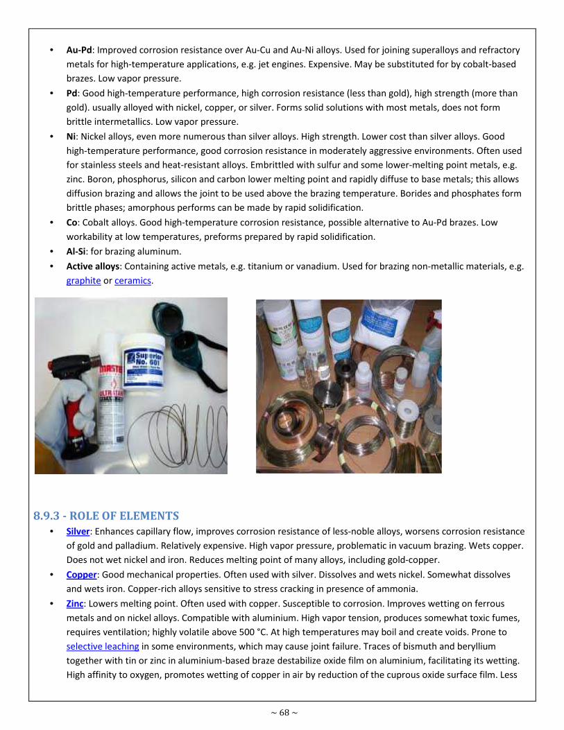
~ 68 ~
• Au-Pd: Improved corrosion resistance over Au-Cu and Au-Ni alloys. Used for joining superalloys and refractory
metals for high-temperature applications, e.g. jet engines. Expensive. May be substituted for by cobalt-based
brazes. Low vapor pressure.
• Pd: Good high-temperature performance, high corrosion resistance (less than gold), high strength (more than
gold). usually alloyed with nickel, copper, or silver. Forms solid solutions with most metals, does not form
brittle intermetallics. Low vapor pressure.
• Ni: Nickel alloys, even more numerous than silver alloys. High strength. Lower cost than silver alloys. Good
high-temperature performance, good corrosion resistance in moderately aggressive environments. Often used
for stainless steels and heat-resistant alloys. Embrittled with sulfur and some lower-melting point metals, e.g.
zinc. Boron, phosphorus, silicon and carbon lower melting point and rapidly diffuse to base metals; this allows
diffusion brazing and allows the joint to be used above the brazing temperature. Borides and phosphates form
brittle phases; amorphous performs can be made by rapid solidification.
• Co: Cobalt alloys. Good high-temperature corrosion resistance, possible alternative to Au-Pd brazes. Low
workability at low temperatures, preforms prepared by rapid solidification.
• Al-Si: for brazing aluminum.
• Active alloys: Containing active metals, e.g. titanium or vanadium. Used for brazing non-metallic materials, e.g.
graphite or ceramics.
8.9.3 - ROLE OF ELEMENTS
• Silver: Enhances capillary flow, improves corrosion resistance of less-noble alloys, worsens corrosion resistance
of gold and palladium. Relatively expensive. High vapor pressure, problematic in vacuum brazing. Wets copper.
Does not wet nickel and iron. Reduces melting point of many alloys, including gold-copper.
• Copper: Good mechanical properties. Often used with silver. Dissolves and wets nickel. Somewhat dissolves
and wets iron. Copper-rich alloys sensitive to stress cracking in presence of ammonia.
• Zinc: Lowers melting point. Often used with copper. Susceptible to corrosion. Improves wetting on ferrous
metals and on nickel alloys. Compatible with aluminium. High vapor tension, produces somewhat toxic fumes,
requires ventilation; highly volatile above 500 °C. At high temperatures may boil and create voids. Prone to
selective leaching in some environments, which may cause joint failure. Traces of bismuth and beryllium
together with tin or zinc in aluminium-based braze destabilize oxide film on aluminium, facilitating its wetting.
High affinity to oxygen, promotes wetting of copper in air by reduction of the cuprous oxide surface film. Less
~ 69 ~
such benefit in furnace brazing with controlled atmosphere. Embrittles nickel. High levels of zinc may result in a
brittle alloy.[17]
• Aluminium: Usual base for brazing aluminium and its alloys. Embrittles ferrous alloys.
• Gold: Excellent corrosion resistance. Very expensive. Wets most metals.
• Palladium: Excellent corrosion resistance, though less than gold. Higher mechanical strength than gold. Good
high-temperature strength. Very expensive, though less than gold. Makes the joint less prone to fail due to
intergranular penetration when brazing alloys of nickel, molybdenum, or tungsten.[18] Increases high-
temperature strength of gold-based alloys.[16] Improves high-temperature strength and corrosion resistance of
gold-copper alloys. Forms solid solutions with most engineering metals, does not form brittle intermetallics.
High oxidation resistance at high temperatures, especially Pd-Ni alloys.
• Cadmium: Lowers melting point, improves fluidity. Toxic. Produces toxic fumes, requires ventilation. High
affinity to oxygen, promotes wetting of copper in air by reduction of the cuprous oxide surface film. Less such
benefit in furnace brazing with controlled atmosphere. Allows reducing silver content of Ag-Cu-Zn alloys.
Replaced by tin in more modern alloys.
• Lead: Lowers melting point. Toxic. Produces toxic fumes, requires ventilation.
• Tin: Lowers melting point, improves fluidity. Broadens melting range. Can be used with copper, with which it
forms bronze. Improves wetting of many difficult-to-wet metals, e.g. stainless steels and tungsten carbide.
Traces of bismuth and beryllium together with tin or zinc in aluminium-based braze destabilize oxide film on
aluminium, facilitating its wetting. Low solubility in zinc, which limits its content in zinc-bearing alloys.[17]
• Bismuth: Lowers melting point. May disrupt surface oxides. Traces of bismuth and beryllium together with tin
or zinc in aluminium-based braze destabilize oxide film on aluminium, facilitating its wetting.[17]
• Beryllium: Traces of bismuth and beryllium together with tin or zinc in aluminium-based braze destabilize oxide
film on aluminium, facilitating its wetting.[17]
• Nickel: Strong, corrosion-resistant. Impedes flow of the melt. Addition to gold-copper alloys improves ductility
and resistance to creep at high temperatures.[16] Addition to silver allows wetting of silver-tungsten alloys and
improves bond strength. Improves wetting of copper-based brazes. Improves ductility of gold-copper brazes.
Improves mechanical properties and corrosion resistance of silver-copper-zinc brazes. Nickel content offsets
brittleness induced by diffusion of aluminium when brazing aluminium-containing alloys, e.g. aluminium
bronzes. In some alloys increases mechanical properties and corrosion resistance, by a combination of solid
solution strengthening, grain refinement, and segregation on fillet surface and in grain boundaries, where it
forms a corrosion-resistant layer. Extensive intersolubility with iron, chromium, manganese, and others; can
severely erode such alloys. Embrittled by zinc, many other low melting point metals, and sulfur.[17]
• Chromium: Corrosion-resistant. Increases high-temperature corrosion and strength of gold-based alloys. Added
to copper and nickel to increase corrosion resistance of them and their alloys.[16] Wets oxides, carbides, and
graphite; frequently a major alloy component for high-temperature brazing of such materials. Impairs wetting
by gold-nickel alloys, which can be compensated for by addition of boron.[17]
• Manganese: High vapor pressure, unsuitable for vacuum brazing. In gold-based alloys increases ductility.
Increases corrosion resistance of copper and nickel alloys.[16] Improves high-temperature strength and
corrosion resistance of gold-copper alloys. Higher manganese content may aggravate tendency to liquation.
Manganese in some alloys may tend to cause porosity in fillets. Tends to react with graphite molds and jigs.
Oxidizes easily, requires flux. Lowers melting point of high-copper brazes. Improves mechanical properties and
corrosion resistance of silver-copper-zinc brazes. Cheap, even less expensive than zinc. Part of the Cu-Zn-Mn
system is brittle, some ratios can not be used.[17] In some alloys increases mechanical properties and corrosion
resistance, by a combination of solid solution strengthening, grain refinement, and segregation on fillet surface
~ 70 ~
and in grain boundaries, where it forms a corrosion-resistant layer. Facilitates wetting of cast iron due to its
ability to dissolve carbon.
• Molybdenum: Increases high-temperature corrosion and strength of gold-based alloys.[16] Increased ductility of
gold-based alloys, promotes their wetting of refractory materials, namely carbides and graphite. When present
in alloys being joined, may destabilize the surface oxide layer (by oxidizing and then volatilizing) and facilitate
wetting.
• Cobalt: Good high-temperature properties and corrosion resistance. In nuclear applications can absorb
neutrons and build up cobalt-60, a potent gamma radiation emitter.
• Magnesium: Addition to aluminium makes the alloy suitable for vacuum brazing. Volatile, though less than zinc.
Vaporization promotes wetting by removing oxides from the surface, vapors act as getter for oxygen in the
furnace atmosphere.
• Indium: Lowers melting point. Improves wetting of ferrous alloys by copper-silver alloys.
• Carbon: Lowers melting point. Can form carbides. Can diffuse to the base metal, resulting in higher remelt
temperature, potentially allowing step-brazing with the same alloy. At above 0.1% worsens corrosion
resistance of nickel alloys. Trace amounts present in stainless steel may facilitate reduction of surface
chromium(III) oxide in vacuum and allow fluxless brazing. Diffusion away from the braze increases its remelt
temperature; exploited in diffusion brazing.[17]
• Silicon: Lowers melting point. Can form silicides. Improves wetting of copper-based brazes. Promotes flow.
Causes intergranular embrittlement of nickel alloys. Rapidly diffuses into the base metals. Diffusion away from
the braze increases its remelt temperature; exploited in diffusion brazing.
• Germanium: Lowers melting point. Expensive. For special applications. May create brittle phases.
• Boron: Lowers melting point. Can form hard and brittle borides. Unsuitable for nuclear reactors. Fast diffusion
to the base metals. Can diffuse to the base metal, resulting in higher remelt temperature, potentially allowing
step-brazing with the same alloy. Can erode some base materials or penetrate between grain boundaries of
many heat-resistant structural alloys, degrading their mechanical properties. Has to be avoided in nuclear
applications due to its interaction with neutrons. Causes intergranular embrittlement of nickel alloys. Improves
wetting of/by some alloys, can be added to Au-Ni-Cr alloy to compensate for wetting loss by chromium
addition. In low concentrations improves wetting and lowers melting point of nickel brazes. Rapidly diffuses to
base materials, may lower their melting point; especially a concern when brazing thin materials. Diffusion away
from the braze increases its remelt temperature; exploited in diffusion brazing.
• Mischmetal, in amount of about 0.08%, can be used to substitute boron where boron would have detrimental
effects.[17]
• Cerium, in trace quantities, improves fluidity of brazes. Particularly useful for alloys of four or more
components, where the other additives compromise flow and spreading.
• Strontium, in trace quantities, refines the grain structure of aluminium-based alloys.
~ 71 ~
8.9.4 - DEOXIDIZERS
• Phosphorus: Lowers melting point. Deoxidizer, decomposes copper oxide; phosphorus-bearing alloys can be
used on copper without flux. Does not decompose zinc oxide, so flux is needed for brass. Forms brittle
phosphides with some metals, e.g. nickel (Ni3P) and iron, phosphorus alloys unsuitable for brazing alloys
bearing iron, nickel or cobalt in amount above 3%. The phosphides segregate at grain boundaries and cause
intergranular embrittlement. (Sometimes the brittle joint is actually desired, though. Fragmentation grenades
can be brazed with phosporus bearing alloy to produce joints that shatter easily at detonation.) Avoid in
environments with presence of sulfur dioxide (e.g. paper mills) and hydrogen sulfide (e.g. sewers, or close to
volcanoes); the phosphorus-rich phase rapidly corrodes in presence of sulfur and the joint fails. Phosphorus can
be also present as an impurity introduced from e.g. electroplating baths.[18] In low concentrations improves
wetting and lowers melting point of nickel brazes. Diffusion away from the braze increases its remelt
temperature; exploited in diffusion brazing.
• Lithium: Deoxidizer. Eliminates the need for flux with some materials. Lithium oxide formed by reaction with
the surface oxides is easily displaced by molten braze alloy.[17]
8.9.5 - ACTIVE METALS
• Titanium: Most commonly used active metal. Few percents added to Ag-Cu alloys facilitate wetting of ceramics,
e.g. silicon nitride.[19] Most metals, except few (namely silver, copper and gold), form brittle phases with
titanium. When brazing ceramics, like other active metals, titanium reacts with them and forms a complex layer
on their surface, which in turn is wettable by the silver-copper braze. Wets oxides, carbides, and graphite;
frequently a major alloy component for high-temperature brazing of such materials.[17]
• Zirconium: Wets oxides, carbides, and graphite; frequently a major alloy component for high-temperature
brazing of such materials.[17]
• Hafnium
• Vanadium: Promotes wetting of alumina ceramics by gold-based alloys.[16]
• Aluminium: Base component of most brazes for aluminium. Embrittles ferrous metals.
8.9.6 - IMPURITIES
• Sulfur: Compromises integrity of nickel alloys. Can enter the joints from residues of lubricants, grease or paint.
Forms brittle nickel sulfide (Ni3S2) that segregates at grain boundaries and cause intergranular failure.
Some additives and impurities act at very low levels. Both positive and negative effects can be observed. Strontium at
levels of 0.01% refines grain structure of aluminium. Beryllium and bismuth at similar levels help disrupt the passivation
layer of aluminium oxide and promote wetting. Carbon at 0.1% impairs corrosion resistance of nickel alloys. Aluminium
can embrittle mild steel at 0.001%, phosphorus at 0.01%.[17]
In some cases, especially for vacuum brazing, high-purity metals and alloys are used. 99.99% and 99.999% purity levels
are available commercially.
Care has to be taken to not introduce deletrious impurities from joint contaminations or by dissolution of the base
metals during brazing.
~ 72 ~
8.9.7 - MELTING BEHAVIOR
Alloys with larger span of solidus/liquidus temperatures tend to melt through a "mushy" state, where the alloy is a
mixture of solid and liquid material. Some alloys show tendency to liquation, separation of the liquid from the solid
portion; for these the heating through the melting range has to be sufficiently fast to avoid this effect. Some alloys
show extended plastic range, when only a small portion of the alloy is liquid and most of the material melts at the
upper temperature range; these are suitable for bridging large gaps and for forming fillets. Highly fluid alloys are
suitable for penetrating deep into narrow gaps and for brazing tight joints with narrow tolerances but are not suitable
for filling larger gaps. Alloys with wider melting range are less sensitive to non-uniform clearances.
When the brazing temperature is suitably high, brazing and heat treatment can be done in a single operation
simultaneously.
Eutectic alloys melt at single temperature, without mushy region. Eutectic alloys have superior spreading; non-eutectics
in the mushy region have high viscosity and at the same time attack the base metal, with correspondingly lower
spreading force. Fine grain size gives eutectics both increased strength and increased ductility. Highly accurate melting
temperature allows joining process to be performed only slightly above the alloy's melting point. On solidifying, there is
no mushy state where the alloy appears solid but is not yet; the chance of disturbing the joint by manipulation in such
state is reduced (assuming the alloy did not significantly change its properties by dissolving the base metal). Eutectic
behavior is especially beneficial for solders.[17]
Metals with fine grain structure before melting provide superior wetting to metals with large grains. Alloying additives
(e.g. strontium to aluminium) can be added to refine grain structure, and the preforms or foils can be prepared by rapid
quenching. Very rapid quenching may provide amorphous metal structure, which possess further advantages.[17]
8.9.8 - INTERACTION WITH BASE METALS
For successful wetting, the base metal has to be at least partially soluble in at least one component of the brazing alloy.
The molten alloy therefore tends to attack the base metal and dissolve it, slightly change its composition in process.
The composition change is reflected in the change of the alloy's melting point and the corresponding change of fluidity.
For example, some alloys dissolve both silver and copper; dissolved silver lowers their melting point and increases
fluidity, copper has the opposite effect.
The melting point change can be exploited. As the remelt temperature can be increased by enriching the alloy with
dissolved base metal, step brazing using the same braze can be possible.
Alloys that do not significantly attack the base metals are more suitable for brazing thin sections.
Nonhomogenous microstructure of the braze may cause non-uniform melting and localized erosions of the base metal.
Wetting of base metals can be improved by adding a suitable metal to the alloy. Tin facilitates wetting of iron, nickel,
and many other alloys. Copper wets ferrous metals that silver does not attack, copper-silver alloys can therefore braze
steels silver alone won't wet. Zinc improves wetting of ferrous metals, indium as well. Aluminium improves wetting of
aluminium alloys. For wetting of ceramics, reactive metals capable of forming chemical compounds with the ceramic
(e.g. titanium, vanadium, zirconium...) can be added to the braze.
Dissolution of base metals can cause detrimental changes in the brazing alloy. For example, aluminium dissolved from
aluminium bronzes can embrittle the braze; addition of nickel to the braze can offset this.
~ 73 ~
The effect works both ways; there can be detrimental interactions between the braze alloy and the base metal.
Presence of phosphorus in the braze alloy leads to formation of brittle phosphides of iron and nickel, phosphorus-
containing alloys are therefore unsuitable for brazing nickel and ferrous alloys. Boron tends to diffuse into the base
metals, especially along the grain boundaries, and may form brittle borides. Carbon can negatively influence some
steels.
Care has to be taken to avoid galvanic corrosion between the braze and the base metal, and especially between
dissimilar base metals being brazed together.
Formation of brittle intermetallic compounds on the alloy interface can cause joint failure. This is discussed more in-
depth with solders.
The potentially detrimental phases may be distributed evenly through the volume of the alloy, or be concentrated on
the braze-base interface. A thick layer of interfacial intermetallics is usually considered detrimental due to its
commonly low fracture toughness and other sub-par mechanical properties. In some situations, e.g. die attaching, it
however does not matter much as silicon chips are not typically subjected to mechanical abuse.[17]
On wetting, brazes may liberate elements from the base metal. For example, aluminium-silicon braze wets silicon
nitride, dissociates the surface so it can react with silicon, and liberates nitrogen, which may create voids along the joint
interface and lower its strength. Titanium-containing nickel-gold braze wets silicon nitride and reacts with its surface,
forming titanium nitride and liberating silicon; silicon then forms brittle nickel silicides and eutectic gold-silicon phase;
the resulting joint is weak and melts at much lower temperature than may be expected.[17]
Metals may diffuse from one base alloy to the other one, causing embrittlement or corrosion. An example is diffusion
of aluminium from aluminium bronze to a ferrous alloy when joining these. A diffusion barrier, e.g. a copper layer (e.g.
in a trimet strip), can be used.
A sacrificial layer of a noble metal can be used on the base metal as an oxygen barrier, preventing formation of oxides
and facilitating fluxless brazing. During brazing, the noble metal layer dissolves in the filler metal. Copper or nickel
plating of stainless steels performs the same function.[17]
In brazing copper, a reducing atmosphere (or even a reducing flame) may react with the oxygen residues in the metal,
which are present as cuprous oxide inclusions, and cause hydrogen embrittlement. The hydrogen present in the flame
or atmosphere at high temperature reacts with the oxide, yielding metallic copper and water vapour, steam. The steam
bubbles exert high pressure in the metal structure, leading to cracks and joint porosity. Oxygen-free copper is not
sensitive to this effect, however the most readily available grades, e.g. electrolytic copper or high-conductivity copper,
are. The embrittled joint may then fail catastrophically without any previous sign of deformation or deterioration.[20]
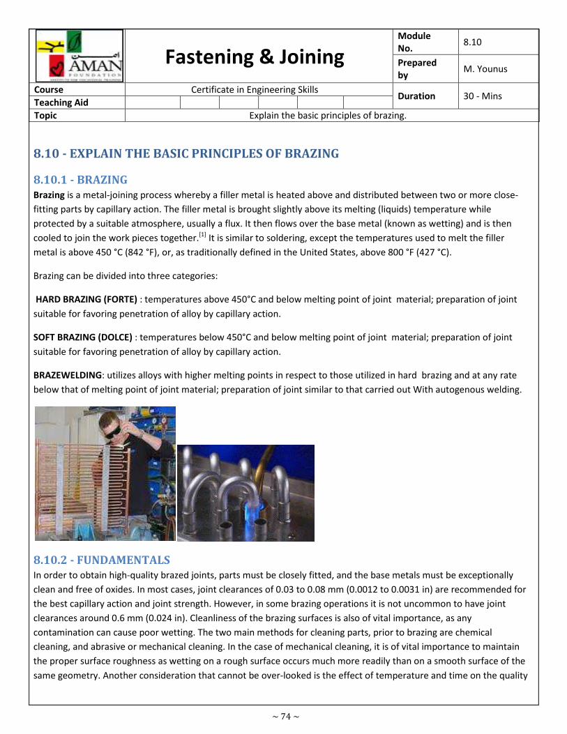
~ 74 ~
Fastening & Joining Module
No. 8.10
Prepared
by M. Younus
Course Certificate in Engineering Skills Duration 30 - Mins
Teaching Aid
Topic Explain the basic principles of brazing.
8.10 - EXPLAIN THE BASIC PRINCIPLES OF BRAZING
8.10.1 - BRAZING
Brazing is a metal-joining process whereby a filler metal is heated above and distributed between two or more close-
fitting parts by capillary action. The filler metal is brought slightly above its melting (liquids) temperature while
protected by a suitable atmosphere, usually a flux. It then flows over the base metal (known as wetting) and is then
cooled to join the work pieces together.[1] It is similar to soldering, except the temperatures used to melt the filler
metal is above 450 °C (842 °F), or, as traditionally defined in the United States, above 800 °F (427 °C).
Brazing can be divided into three categories:
HARD BRAZING (FORTE) : temperatures above 450°C and below melting point of joint material; preparation of joint
suitable for favoring penetration of alloy by capillary action.
SOFT BRAZING (DOLCE) : temperatures below 450°C and below melting point of joint material; preparation of joint
suitable for favoring penetration of alloy by capillary action.
BRAZEWELDING: utilizes alloys with higher melting points in respect to those utilized in hard brazing and at any rate
below that of melting point of joint material; preparation of joint similar to that carried out With autogenous welding.
8.10.2 - FUNDAMENTALS
In order to obtain high-quality brazed joints, parts must be closely fitted, and the base metals must be exceptionally
clean and free of oxides. In most cases, joint clearances of 0.03 to 0.08 mm (0.0012 to 0.0031 in) are recommended for
the best capillary action and joint strength. However, in some brazing operations it is not uncommon to have joint
clearances around 0.6 mm (0.024 in). Cleanliness of the brazing surfaces is also of vital importance, as any
contamination can cause poor wetting. The two main methods for cleaning parts, prior to brazing are chemical
cleaning, and abrasive or mechanical cleaning. In the case of mechanical cleaning, it is of vital importance to maintain
the proper surface roughness as wetting on a rough surface occurs much more readily than on a smooth surface of the
same geometry. Another consideration that cannot be over-looked is the effect of temperature and time on the quality
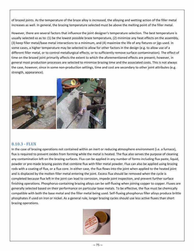
~ 75 ~
of brazed joints. As the temperature of the braze alloy is increased, the alloying and wetting action of the filler metal
increases as well. In general, the brazing temperature selected must be above the melting point of the filler metal.
However, there are several factors that influence the joint designer's temperature selection. The best temperature is
usually selected so as to: (1) be the lowest possible braze temperature, (2) minimize any heat effects on the assembly,
(3) keep filler metal/base metal interactions to a minimum, and (4) maximize the life of any fixtures or jigs used. In
some cases, a higher temperature may be selected to allow for other factors in the design (e.g. to allow use of a
different filler metal, or to control metallurgical effects, or to sufficiently remove surface contamination). The effect of
time on the brazed joint primarily affects the extent to which the aforementioned effects are present; however, in
general most production processes are selected to minimize brazing time and the associated costs. This is not always
the case, however, since in some non-production settings, time and cost are secondary to other joint attributes (e.g.
strength, appearance).
8.10.3 - FLUX
In the case of brazing operations not contained within an inert or reducing atmosphere environment (i.e. a furnace),
flux is required to prevent oxides from forming while the metal is heated. The flux also serves the purpose of cleaning
any contamination left on the brazing surfaces. Flux can be applied in any number of forms including flux paste, liquid,
powder or pre-made brazing pastes that combine flux with filler metal powder. Flux can also be applied using brazing
rods with a coating of flux, or a flux core. In either case, the flux flows into the joint when applied to the heated joint
and is displaced by the molten filler metal entering the joint. Excess flux should be removed when the cycle is
completed because flux left in the joint can lead to corrosion, impede joint inspection, and prevent further surface
finishing operations. Phosphorus-containing brazing alloys can be self-fluxing when joining copper to copper. Fluxes are
generally selected based on their performance on particular base metals. To be effective, the flux must be chemically
compatible with both the base metal and the filler metal being used. Self-fluxing phosphorus filler alloys produce brittle
phosphates if used on iron or nickel. As a general rule, longer brazing cycles should use less active fluxes than short
brazing operations.
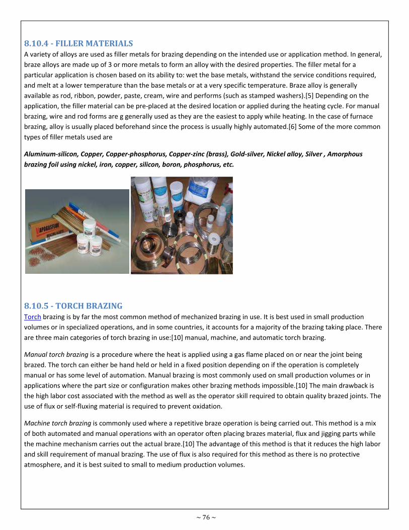
~ 76 ~
8.10.4 - FILLER MATERIALS
A variety of alloys are used as filler metals for brazing depending on the intended use or application method. In general,
braze alloys are made up of 3 or more metals to form an alloy with the desired properties. The filler metal for a
particular application is chosen based on its ability to: wet the base metals, withstand the service conditions required,
and melt at a lower temperature than the base metals or at a very specific temperature. Braze alloy is generally
available as rod, ribbon, powder, paste, cream, wire and performs (such as stamped washers).[5] Depending on the
application, the filler material can be pre-placed at the desired location or applied during the heating cycle. For manual
brazing, wire and rod forms are g generally used as they are the easiest to apply while heating. In the case of furnace
brazing, alloy is usually placed beforehand since the process is usually highly automated.[6] Some of the more common
types of filler metals used are
Aluminum-silicon, Copper, Copper-phosphorus, Copper-zinc (brass), Gold-silver, Nickel alloy, Silver , Amorphous
brazing foil using nickel, iron, copper, silicon, boron, phosphorus, etc.
8.10.5 - TORCH BRAZING
Torch brazing is by far the most common method of mechanized brazing in use. It is best used in small production
volumes or in specialized operations, and in some countries, it accounts for a majority of the brazing taking place. There
are three main categories of torch brazing in use:[10] manual, machine, and automatic torch brazing.
Manual torch brazing is a procedure where the heat is applied using a gas flame placed on or near the joint being
brazed. The torch can either be hand held or held in a fixed position depending on if the operation is completely
manual or has some level of automation. Manual brazing is most commonly used on small production volumes or in
applications where the part size or configuration makes other brazing methods impossible.[10] The main drawback is
the high labor cost associated with the method as well as the operator skill required to obtain quality brazed joints. The
use of flux or self-fluxing material is required to prevent oxidation.
Machine torch brazing is commonly used where a repetitive braze operation is being carried out. This method is a mix
of both automated and manual operations with an operator often placing brazes material, flux and jigging parts while
the machine mechanism carries out the actual braze.[10] The advantage of this method is that it reduces the high labor
and skill requirement of manual brazing. The use of flux is also required for this method as there is no protective
atmosphere, and it is best suited to small to medium production volumes.
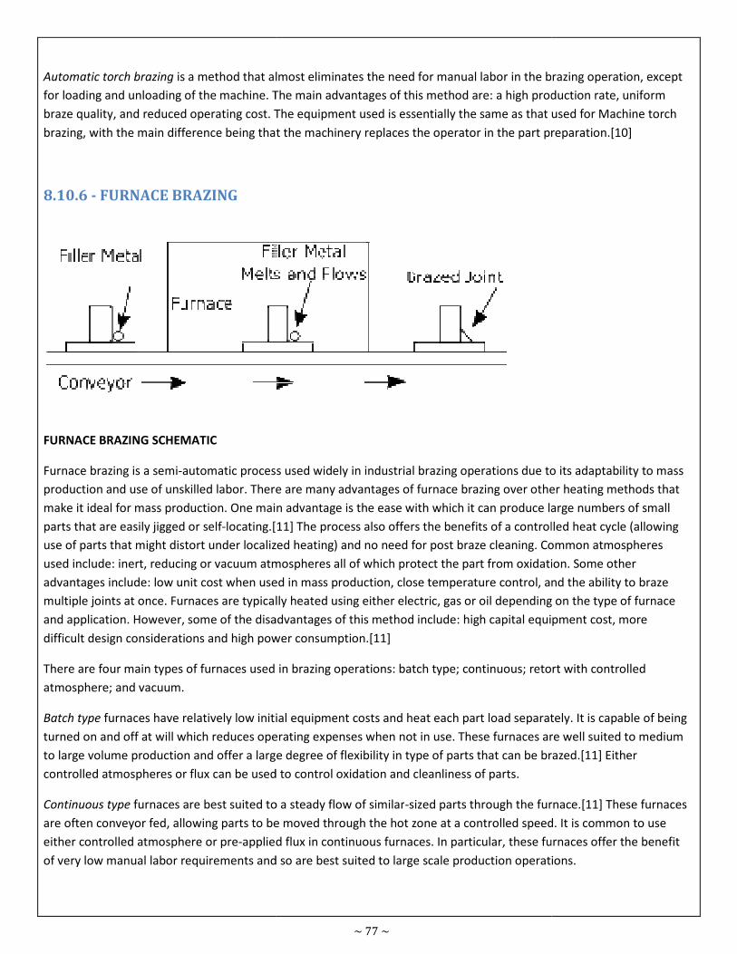
Automatic torch brazing is a method that almost eliminates the need for manual labor in the brazing operation, except
for loading and unloading of the machine. The main advantages of this method are: a high production rate, uniform
braze quality, and reduced operating cost. The equipment used is essentially the same as that used for Machine torch
brazing, with the main difference being that the machinery replaces the operator in the part preparation.
8.10.6 - FURNACE BRAZING
FURNACE BRAZING SCHEMATIC
Furnace brazing is a semi-automatic process used widely in industrial brazing operations due to its adaptability to mass
production and use of unskilled labor. There are many advantages of furnace brazing over other heating methods that
make it ideal for mass production. One main advantage is the ease with which it can
parts that are easily jigged or self-locating.[11]
use of parts that might distort under localized heating) and no need for post braze cleaning. Common atmospheres
used include: inert, reducing or vacuum atmospheres all of which protect the part from oxidation. Some other
advantages include: low unit cost when used in mass production, close temperature control, and the ability to braze
multiple joints at once. Furnaces are typically heated using either electric, gas or oil depending on the type of furnace
and application. However, some of the disadvantages of this method include: high capital equipment cost, more
difficult design considerations and high power consumption.
There are four main types of furnaces used in brazing operations: batch type; continuous;
atmosphere; and vacuum.
Batch type furnaces have relatively low initial equipment costs and heat each part load separately.
turned on and off at will which reduces operating expenses when not in use. These furnaces are well suited to medium
to large volume production and offer a large degree of flexibility in type of parts that can be brazed.
controlled atmospheres or flux can be used to control oxidation and cleanliness of parts.
Continuous type furnaces are best suited to a steady flow of similar
are often conveyor fed, allowing parts to be moved through the hot zone at a controlled speed. It is common to use
either controlled atmosphere or pre-applied flux in continuous furnaces. In particular, these furnaces offer the benefit
of very low manual labor requirements and so are best suited to large scale production operations.
~ 77 ~
is a method that almost eliminates the need for manual labor in the brazing operation, except
for loading and unloading of the machine. The main advantages of this method are: a high production rate, uniform
operating cost. The equipment used is essentially the same as that used for Machine torch
brazing, with the main difference being that the machinery replaces the operator in the part preparation.
automatic process used widely in industrial brazing operations due to its adaptability to mass
. There are many advantages of furnace brazing over other heating methods that
make it ideal for mass production. One main advantage is the ease with which it can produce large numbers of small
[11] The process also offers the benefits of a controlled heat cycle (allowing
distort under localized heating) and no need for post braze cleaning. Common atmospheres
atmospheres all of which protect the part from oxidation. Some other
ges include: low unit cost when used in mass production, close temperature control, and the ability to braze
multiple joints at once. Furnaces are typically heated using either electric, gas or oil depending on the type of furnace
some of the disadvantages of this method include: high capital equipment cost, more
difficult design considerations and high power consumption.[11]
urnaces used in brazing operations: batch type; continuous; retort
furnaces have relatively low initial equipment costs and heat each part load separately.
turned on and off at will which reduces operating expenses when not in use. These furnaces are well suited to medium
to large volume production and offer a large degree of flexibility in type of parts that can be brazed.
controlled atmospheres or flux can be used to control oxidation and cleanliness of parts.
furnaces are best suited to a steady flow of similar-sized parts through the furnace.
are often conveyor fed, allowing parts to be moved through the hot zone at a controlled speed. It is common to use
applied flux in continuous furnaces. In particular, these furnaces offer the benefit
of very low manual labor requirements and so are best suited to large scale production operations.
is a method that almost eliminates the need for manual labor in the brazing operation, except
for loading and unloading of the machine. The main advantages of this method are: a high production rate, uniform
operating cost. The equipment used is essentially the same as that used for Machine torch
brazing, with the main difference being that the machinery replaces the operator in the part preparation.[10]
automatic process used widely in industrial brazing operations due to its adaptability to mass
. There are many advantages of furnace brazing over other heating methods that
produce large numbers of small
The process also offers the benefits of a controlled heat cycle (allowing
distort under localized heating) and no need for post braze cleaning. Common atmospheres
atmospheres all of which protect the part from oxidation. Some other
ges include: low unit cost when used in mass production, close temperature control, and the ability to braze
multiple joints at once. Furnaces are typically heated using either electric, gas or oil depending on the type of furnace
some of the disadvantages of this method include: high capital equipment cost, more
retort with controlled
furnaces have relatively low initial equipment costs and heat each part load separately. It is capable of being
turned on and off at will which reduces operating expenses when not in use. These furnaces are well suited to medium
to large volume production and offer a large degree of flexibility in type of parts that can be brazed.[11] Either
the furnace.[11] These furnaces
are often conveyor fed, allowing parts to be moved through the hot zone at a controlled speed. It is common to use
applied flux in continuous furnaces. In particular, these furnaces offer the benefit
of very low manual labor requirements and so are best suited to large scale production operations.
~ 78 ~
Retort-type furnaces differ from other batch-type furnaces in that they make use of a sealed lining called a "retort". The
retort is generally sealed with either a gasket or is welded shut and filled completely with the desired atmosphere and
then heated externally by conventional heating elements.[11] Due to the high temperatures involved, the retort usually
made of heat resistant alloys that resist oxidation. Retort furnaces are often either used in a batch or semi-continuous
versions.
Vacuum furnaces is a relatively economical method of oxide prevention and is most often used to braze materials with
very stable oxides (aluminum, titanium and zirconium) that cannot be brazed in atmosphere furnaces. Vacuum brazing
is also used heavily with refractory materials and other exotic alloy combinations unsuited to atmosphere furnaces.
Due to the absence of flux or a reducing atmosphere, the part cleanliness is critical when brazing in a vacuum. The
three main types of vacuum furnace are: single-wall hot retort, double-walled hot retort, and cold-wall retort. Typical
vacuum levels for brazing range from pressures of 1.3 to 0.13 pascals (10−2 to 10−3 Torr) to 0.00013 Pa (10−6 Torr) or
lower.[11] Vacuum furnaces are most commonly batch-type, and they are suited to medium and high production
volumes.
8.10.7 - SILVER BRAZING
Silver brazing, colloquially (however, incorrectly) known as a silver soldering or hard soldering, is brazing using a silver
alloy based filler. These silver alloys consist of many different percentages of silver and other metals, such as copper,
zinc and cadmium.
Brazing is widely used in the tool industry to fasten hardmetal (carbide, ceramics, cermet, and similar) tips to tools such
as saw blades. "Pretinning" is often done: the braze alloy is melted onto the hardmetal tip, which is placed next to the
steel and remelted. Pretinning gets around the problem that hardmetals are hard to wet.
Brazed hardmetal joints are typically two to seven mils thick. The braze alloy joins the materials and compensates for
the difference in their expansion rates. In addition it provides a cushion between the hard carbide tip and the hard steel
which softens impact and prevents tip loss and damage, much as the suspension on a vehicle helps prevent damage to
both the tires and the vehicle. Finally the braze alloy joins the other two materials to create a composite structure,
much as layers of wood and glue create plywood.
The standard for braze joint strength in many industries is a joint that is stronger than either base material, so that
when under stress, one or other of the base materials fails before the joint.
One special silver brazing method is called pinbrazing or pin brazing. It has been developed especially for connecting
cables to railway track or for cathodic protection installations. The method uses a silver- and flux-containing brazing pin
which is melted down in the eye of a cable lug. The equipment is normally powered from batteries.
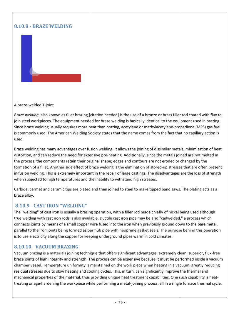
8.10.8 - BRAZE WELDING
A braze-welded T-joint
Braze welding, also known as fillet brazing,[
join steel workpieces. The equipment needed for braze welding is basically identical to the equipment used
Since braze welding usually requires more heat than brazing,
is commonly used. The American Welding Society states that the name comes from the fact that no capillary action is
used.
Braze welding has many advantages over fusion welding. It allows the joining of dissimilar metals,
distortion, and can reduce the need for extensive pre
the process, the components retain their original shape; edges and contours are not eroded or changed by the
formation of a fillet. Another side effect of braze welding is the elimination of stored
in fusion welding. This is extremely important in the repair of large castings. The disadvantages are the loss of strength
when subjected to high temperatures and the inability to withstand high stresses.
Carbide, cermet and ceramic tips are plated and then joined to steel to make tipped band saws. The plating acts as a
braze alloy.
8.10.9 - CAST IRON "WELDING"
The "welding" of cast iron is usually a brazing operation, with a filler rod made chiefly of
true welding with cast iron rods is also available. Ductile cast iron pipe may be also "cadwelded," a process which
connects joints by means of a small copper wire fused into the iron when previously ground down to the bare metal,
parallel to the iron joints being formed as per hub pipe with neoprene gasket seals. The purpose behind this operation
is to use electricity along the copper for keeping underground pipes warm in cold climates.
8.10.10 - VACUUM BRAZING
Vacuum brazing is a materials joining technique that offers significant advantages: extremely clean, superior, flux
braze joints of high integrity and strength. The process can be expensive because it must be performed inside a vacuum
chamber vessel. Temperature uniformity is maintained on the work piece when heating in a vacuum, greatly reducing
residual stresses due to slow heating and cooling cycles. This, in turn, can significantly improve the thermal and
mechanical properties of the material, thus providing unique heat t
treating or age-hardening the workpiece while performing a metal
~ 79 ~
, also known as fillet brazing,[citation needed] is the use of a bronze or brass filler rod coated with flux to
workpieces. The equipment needed for braze welding is basically identical to the equipment used
Since braze welding usually requires more heat than brazing, acetylene or methylacetylene-propadiene (MPS) gas
is commonly used. The American Welding Society states that the name comes from the fact that no capillary action is
Braze welding has many advantages over fusion welding. It allows the joining of dissimilar metals,
distortion, and can reduce the need for extensive pre-heating. Additionally, since the metals joined are not melted in
the process, the components retain their original shape; edges and contours are not eroded or changed by the
on of a fillet. Another side effect of braze welding is the elimination of stored-up stresses that are often present
in fusion welding. This is extremely important in the repair of large castings. The disadvantages are the loss of strength
o high temperatures and the inability to withstand high stresses.
and ceramic tips are plated and then joined to steel to make tipped band saws. The plating acts as a
is usually a brazing operation, with a filler rod made chiefly of nickel
true welding with cast iron rods is also available. Ductile cast iron pipe may be also "cadwelded," a process which
connects joints by means of a small copper wire fused into the iron when previously ground down to the bare metal,
llel to the iron joints being formed as per hub pipe with neoprene gasket seals. The purpose behind this operation
is to use electricity along the copper for keeping underground pipes warm in cold climates.
rials joining technique that offers significant advantages: extremely clean, superior, flux
braze joints of high integrity and strength. The process can be expensive because it must be performed inside a vacuum
s maintained on the work piece when heating in a vacuum, greatly reducing
residual stresses due to slow heating and cooling cycles. This, in turn, can significantly improve the thermal and
mechanical properties of the material, thus providing unique heat treatment capabilities. One such capability is heat
hardening the workpiece while performing a metal-joining process, all in a single furnace thermal cycle.
filler rod coated with flux to
workpieces. The equipment needed for braze welding is basically identical to the equipment used in brazing.
propadiene (MPS) gas fuel
is commonly used. The American Welding Society states that the name comes from the fact that no capillary action is
Braze welding has many advantages over fusion welding. It allows the joining of dissimilar metals, minimization of heat
heating. Additionally, since the metals joined are not melted in
the process, the components retain their original shape; edges and contours are not eroded or changed by the
up stresses that are often present
in fusion welding. This is extremely important in the repair of large castings. The disadvantages are the loss of strength
and ceramic tips are plated and then joined to steel to make tipped band saws. The plating acts as a
being used although
true welding with cast iron rods is also available. Ductile cast iron pipe may be also "cadwelded," a process which
connects joints by means of a small copper wire fused into the iron when previously ground down to the bare metal,
llel to the iron joints being formed as per hub pipe with neoprene gasket seals. The purpose behind this operation
rials joining technique that offers significant advantages: extremely clean, superior, flux-free
braze joints of high integrity and strength. The process can be expensive because it must be performed inside a vacuum
s maintained on the work piece when heating in a vacuum, greatly reducing
residual stresses due to slow heating and cooling cycles. This, in turn, can significantly improve the thermal and
reatment capabilities. One such capability is heat-
joining process, all in a single furnace thermal cycle.
~ 80 ~
Vacuum brazing is often conducted in a furnace; this means that several joints can be made at once because the whole
workpiece reaches the brazing temperature. The heat is transferred using radiation, as many other methods cannot be
used in a vacuum.
8.10.11 - DIP BRAZING
Dip brazing is especially suited for brazing aluminum because air is excluded, thus preventing the formation of oxides.
The parts to be joined are fixtured and the brazing compound applied to the mating surfaces, typically in slurry form.
Then the assemblies are dipped into a bath of molten salt (typically NaCl, KCl and other compounds) which functions
both as heat transfer medium and flux.
8.10.12 - HEATING METHODS
There are many heating methods available to accomplish brazing operations. The most important factor in choosing a
heating method is achieving efficient transfer of heat throughout the joint and doing so within the heat capacity of the
individual base metals used. The geometry of the braze joint is also a crucial factor to consider, as is the rate and
volume of production required. The easiest way to categorize brazing methods is to group them by heating method.
Here are some of the most common:[1][12]
• Torch brazing
• Furnace brazing
• Induction brazing
• Dip brazing
• Resistance brazing
• Infrared brazing
• Blanket brazing
• Electron beam and laser brazing
• Braze welding
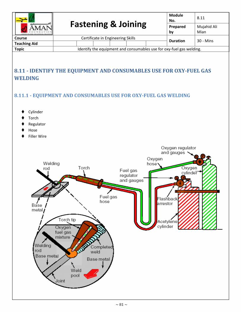
~ 81 ~
Fastening & Joining Module
No. 8.11
Prepared
by
Mujahid Ali
Mian
Course Certificate in Engineering Skills Duration 30 - Mins
Teaching Aid
Topic Identify the equipment and consumables use for oxy-fuel gas welding.
8.11 - IDENTIFY THE EQUIPMENT AND CONSUMABLES USE FOR OXY-FUEL GAS
WELDING
8.11.1 - EQUIPMENT AND CONSUMABLES USE FOR OXY-FUEL GAS WELDING
� Cylinder
� Torch
� Regulator
� Hose
� Filler Wire
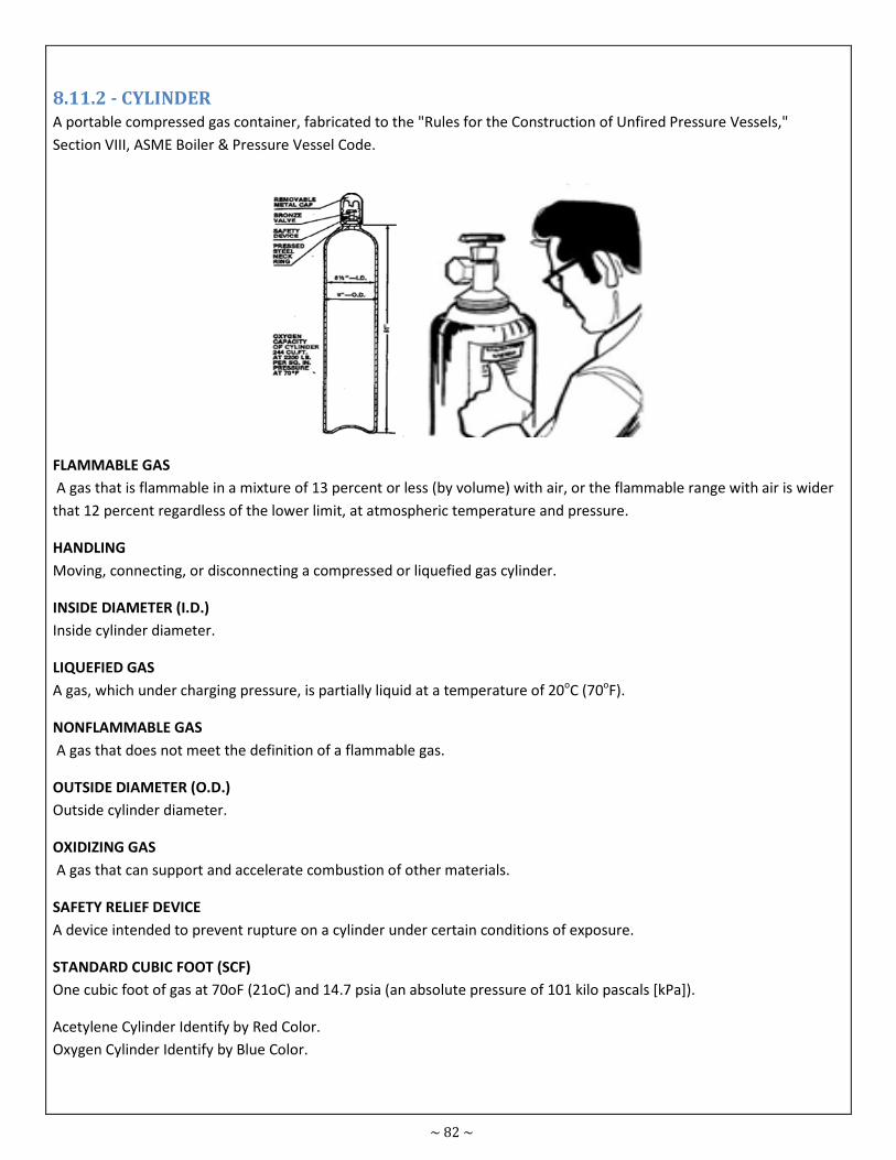
~ 82 ~
8.11.2 - CYLINDER
A portable compressed gas container, fabricated to the "Rules for the Construction of Unfired Pressure Vessels,"
Section VIII, ASME Boiler & Pressure Vessel Code.
FLAMMABLE GAS
A gas that is flammable in a mixture of 13 percent or less (by volume) with air, or the flammable range with air is wider
that 12 percent regardless of the lower limit, at atmospheric temperature and pressure.
HANDLING
Moving, connecting, or disconnecting a compressed or liquefied gas cylinder.
INSIDE DIAMETER (I.D.)
Inside cylinder diameter.
LIQUEFIED GAS
A gas, which under charging pressure, is partially liquid at a temperature of 20oC (70oF).
NONFLAMMABLE GAS
A gas that does not meet the definition of a flammable gas.
OUTSIDE DIAMETER (O.D.)
Outside cylinder diameter.
OXIDIZING GAS
A gas that can support and accelerate combustion of other materials.
SAFETY RELIEF DEVICE
A device intended to prevent rupture on a cylinder under certain conditions of exposure.
STANDARD CUBIC FOOT (SCF)
One cubic foot of gas at 70oF (21oC) and 14.7 psia (an absolute pressure of 101 kilo pascals [kPa]).
Acetylene Cylinder Identify by Red Color.
Oxygen Cylinder Identify by Blue Color.
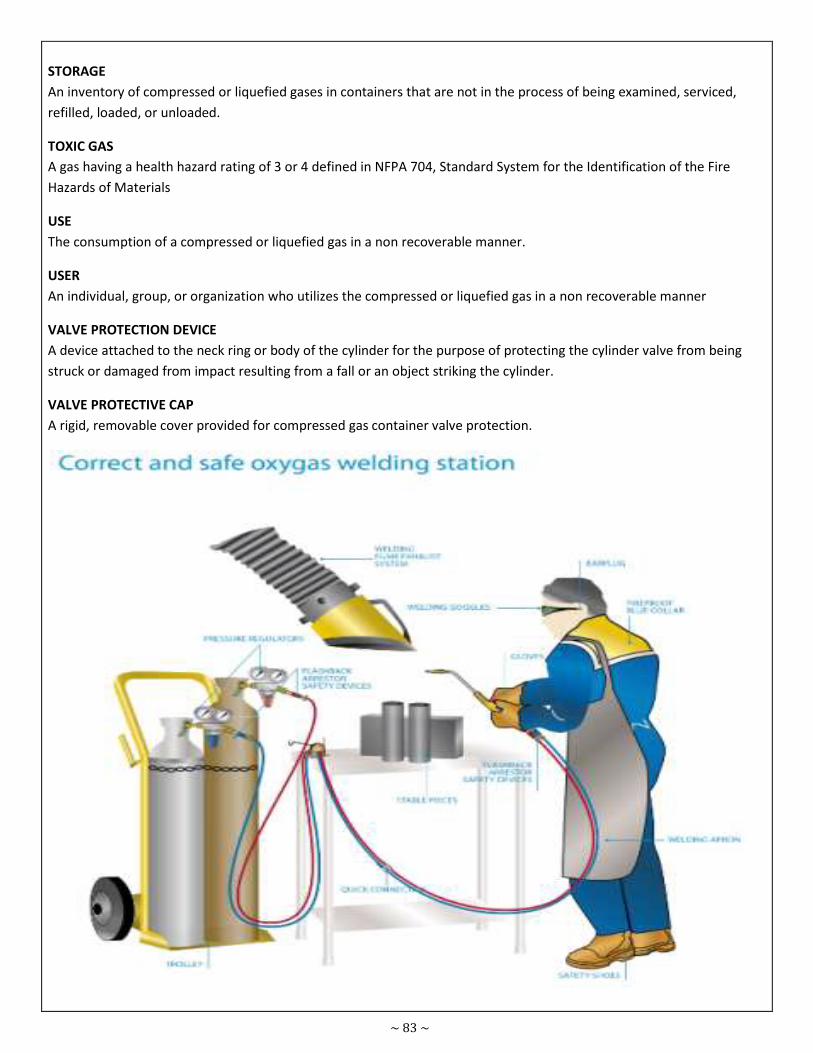
~ 83 ~
STORAGE
An inventory of compressed or liquefied gases in containers that are not in the process of being examined, serviced,
refilled, loaded, or unloaded.
TOXIC GAS
A gas having a health hazard rating of 3 or 4 defined in NFPA 704, Standard System for the Identification of the Fire
Hazards of Materials
USE
The consumption of a compressed or liquefied gas in a non recoverable manner.
USER
An individual, group, or organization who utilizes the compressed or liquefied gas in a non recoverable manner
VALVE PROTECTION DEVICE
A device attached to the neck ring or body of the cylinder for the purpose of protecting the cylinder valve from being
struck or damaged from impact resulting from a fall or an object striking the cylinder.
VALVE PROTECTIVE CAP
A rigid, removable cover provided for compressed gas container valve protection.
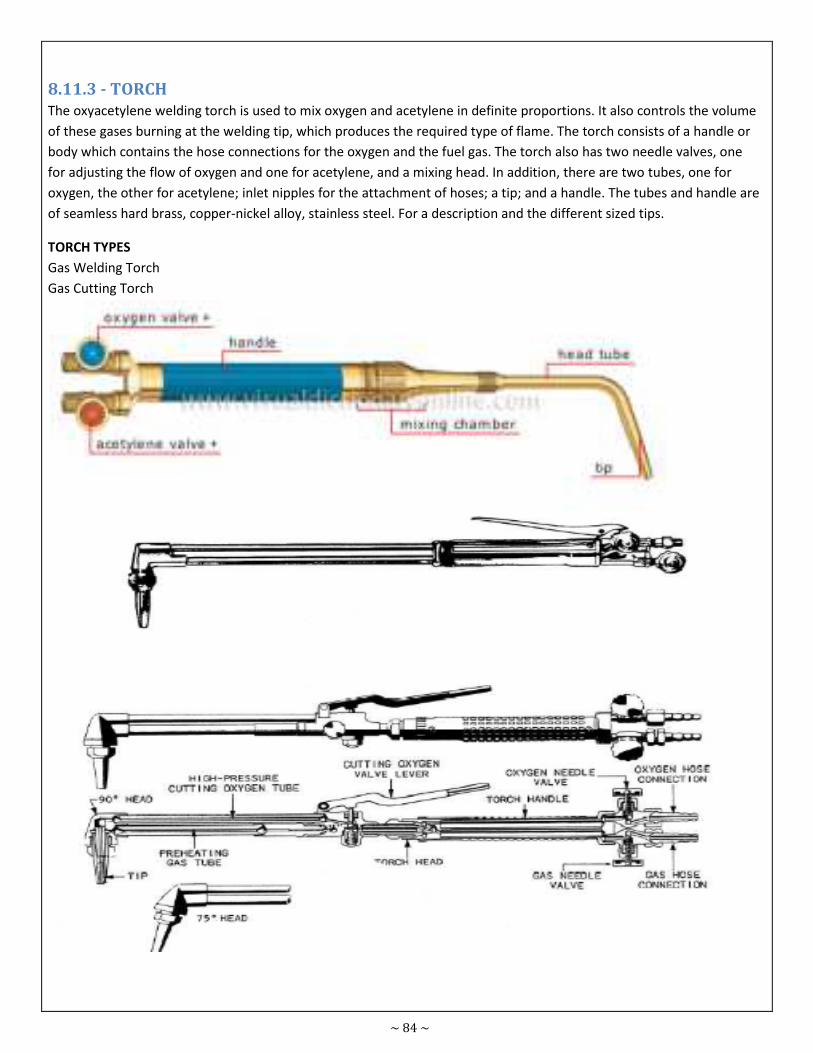
~ 84 ~
8.11.3 - TORCH
The oxyacetylene welding torch is used to mix oxygen and acetylene in definite proportions. It also controls the volume
of these gases burning at the welding tip, which produces the required type of flame. The torch consists of a handle or
body which contains the hose connections for the oxygen and the fuel gas. The torch also has two needle valves, one
for adjusting the flow of oxygen and one for acetylene, and a mixing head. In addition, there are two tubes, one for
oxygen, the other for acetylene; inlet nipples for the attachment of hoses; a tip; and a handle. The tubes and handle are
of seamless hard brass, copper-nickel alloy, stainless steel. For a description and the different sized tips.
TORCH TYPES
Gas Welding Torch
Gas Cutting Torch
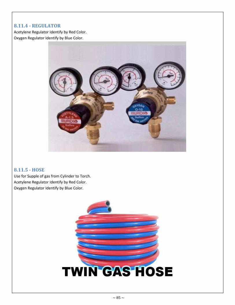
~ 85 ~
8.11.4 - REGULATOR
Acetylene Regulator Identify by Red Color.
Oxygen Regulator Identify by Blue Color.
8.11.5 - HOSE
Use for Supple of gas from Cylinder to Torch.
Acetylene Regulator Identify by Red Color.
Oxygen Regulator Identify by Blue Color.
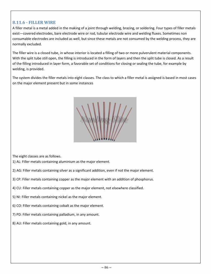
~ 86 ~
8.11.6 - FILLER WIRE
A filler metal is a metal added in the making of a joint through welding, brazing, or soldering. Four types of filler metals
exist—covered electrodes, bare electrode wire or rod, tubular electrode wire and welding fluxes. Sometimes non
consumable electrodes are included as well, but since these metals are not consumed by the welding process, they are
normally excluded.
The filler wire is a closed tube, in whose interior is located a filling of two or more pulverulent material components.
With the split tube still open, the filling is introduced in the form of layers and then the split tube is closed. As a result
of the filling introduced in layer form, a favorable set of conditions for closing or sealing the tube, for example by
welding, is provided.
The system divides the filler metals into eight classes. The class to which a filler metal is assigned is based in most cases
on the major element present but in some instances
The eight classes are as follows.
1) AL: Filler metals containing aluminium as the major element.
2) AG: Filler metals containing silver as a significant addition, even if not the major element.
3) CP: Filler metals containing copper as the major element with an addition of phosphorus.
4) CU: Filler metals containing copper as the major element, not elsewhere classified.
5) NI: Filler metals containing nickel as the major element.
6) CO: Filler metals containing cobalt as the major element.
7) PD: Filler metals containing palladium, in any amount.
8) AU: Filler metals containing gold, in any amount.
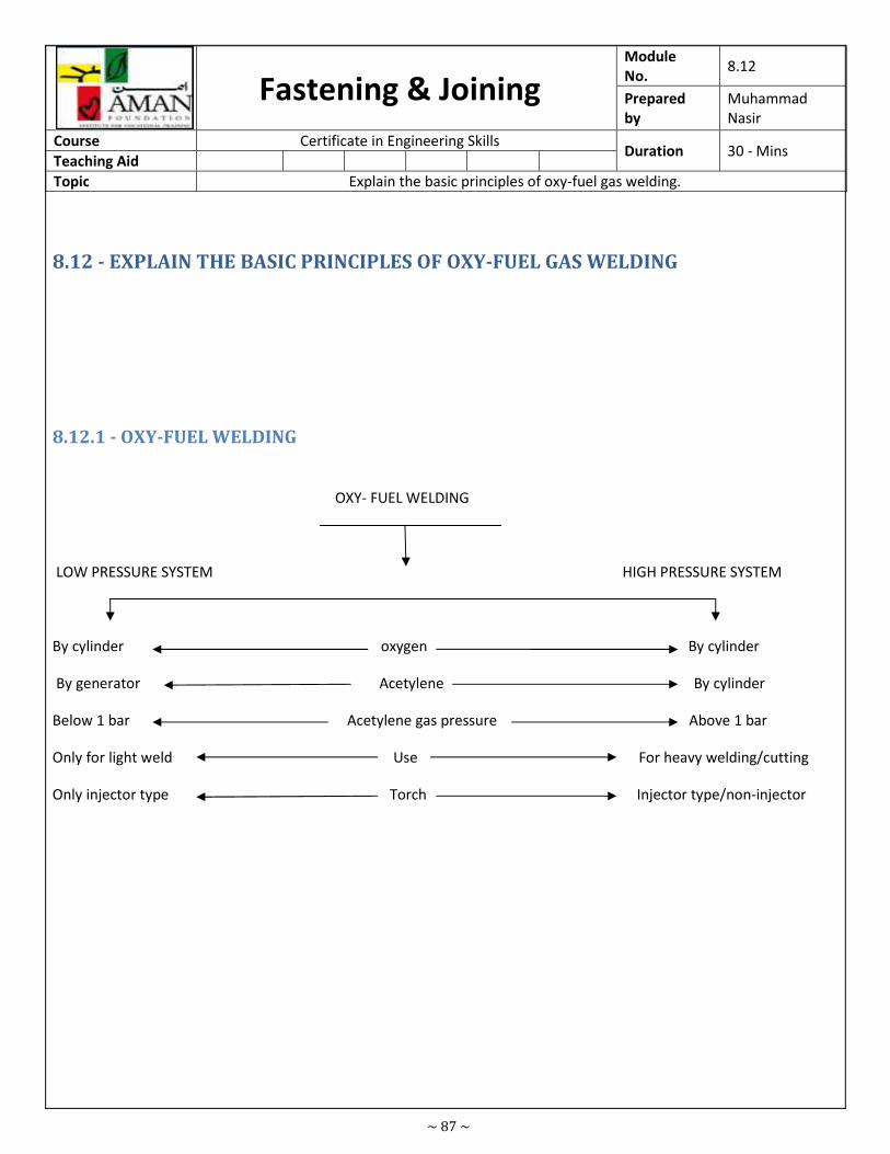
~ 87 ~
Fastening & Joining Module
No. 8.12
Prepared
by
Muhammad
Nasir
Course Certificate in Engineering Skills Duration 30 - Mins
Teaching Aid
Topic Explain the basic principles of oxy-fuel gas welding.
8.12 - EXPLAIN THE BASIC PRINCIPLES OF OXY-FUEL GAS WELDING
8.12.1 - OXY-FUEL WELDING
OXY- FUEL WELDING
LOW PRESSURE SYSTEM HIGH PRESSURE SYSTEM
By cylinder oxygen By cylinder
By generator Acetylene By cylinder
Below 1 bar Acetylene gas pressure Above 1 bar
Only for light weld Use For heavy welding/cutting
Only injector type Torch Injector type/non-injector
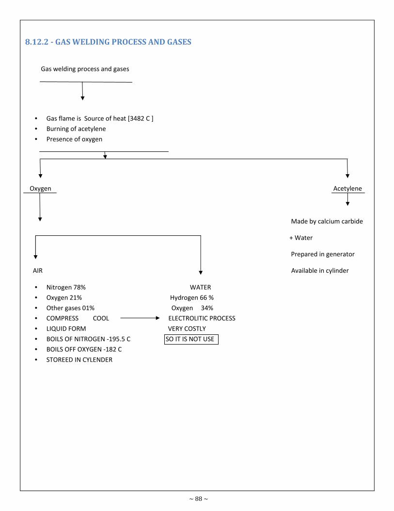
~ 88 ~
8.12.2 - GAS WELDING PROCESS AND GASES
Gas welding process and gases
• Gas flame is Source of heat [3482 C ]
• Burning of acetylene
• Presence of oxygen
Oxygen Acetylene
Made by calcium carbide
+ Water
Prepared in generator
AIR Available in cylinder
• Nitrogen 78% WATER
• Oxygen 21% Hydrogen 66 %
• Other gases 01% Oxygen 34%
• COMPRESS COOL ELECTROLITIC PROCESS
• LIQUID FORM VERY COSTLY
• BOILS OF NITROGEN -195.5 C SO IT IS NOT USE
• BOILS OFF OXYGEN -182 C
• STOREED IN CYLENDER
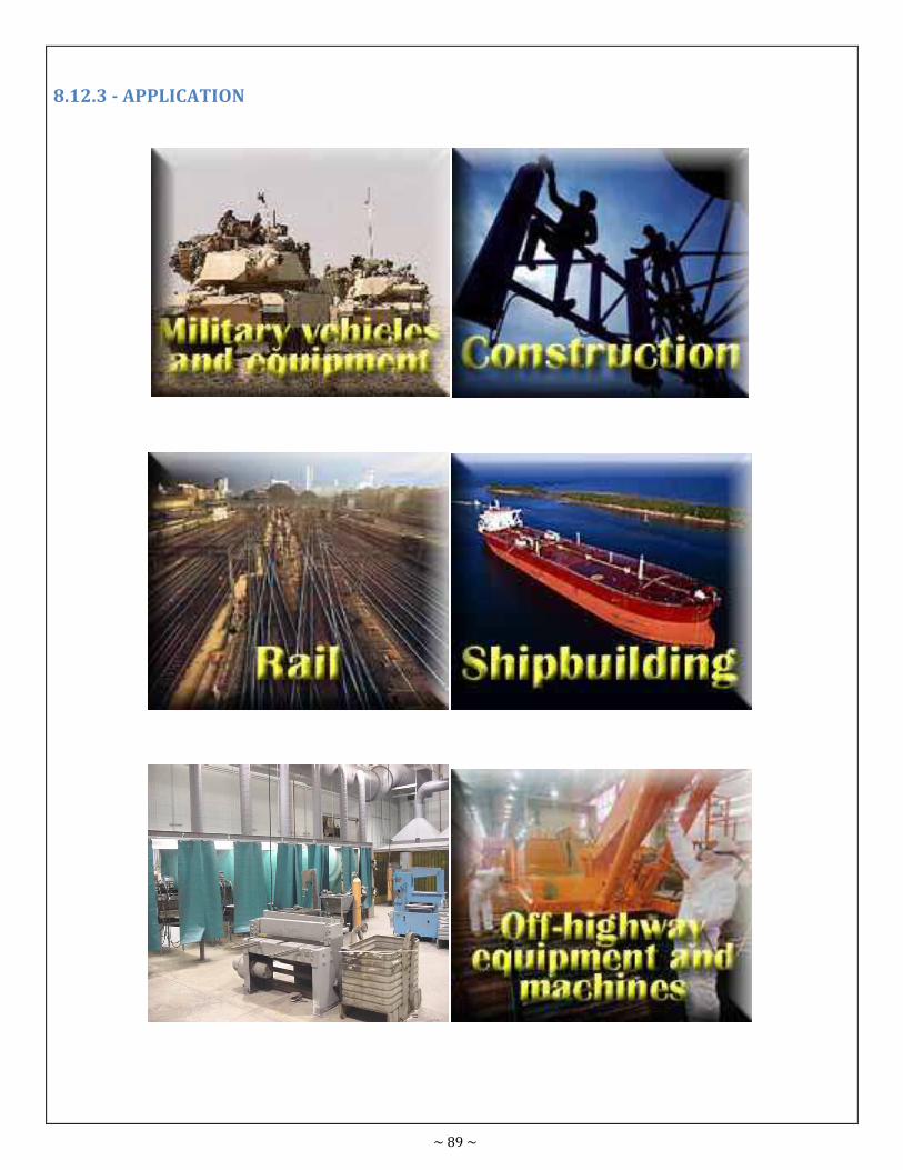
~ 89 ~
8.12.3 - APPLICATION
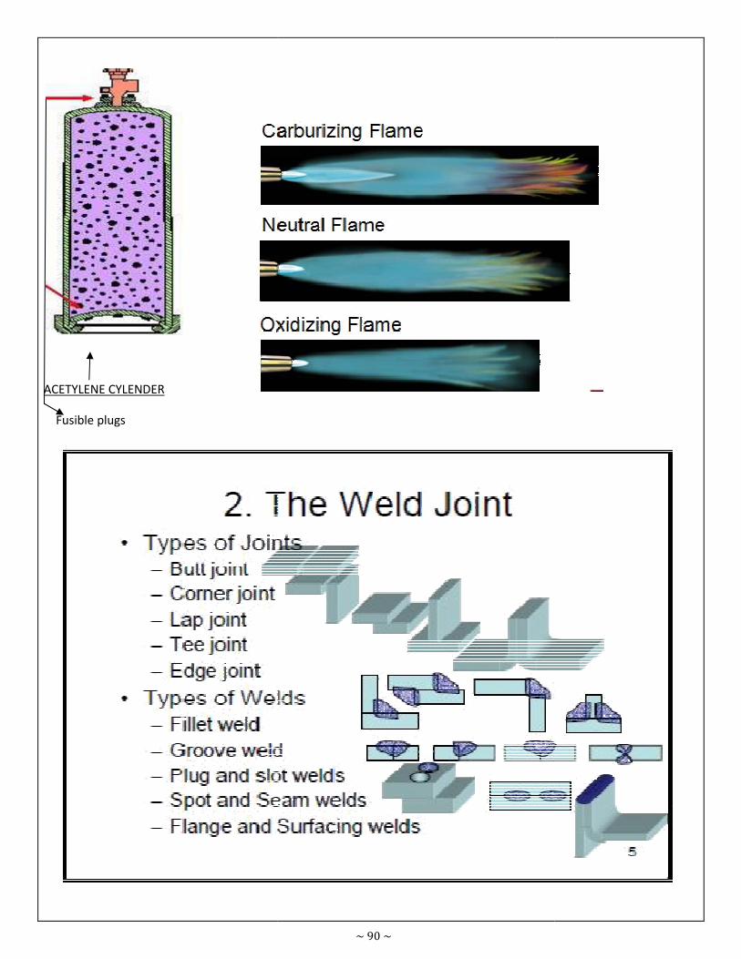
ACETYLENE CYLENDER
Fusible plugs
~ 90 ~
Fusible plugs
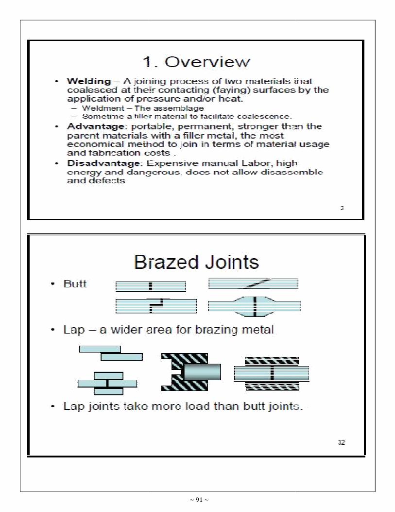
~ 91 ~
~ 92 ~

~ 93 ~

~ 94 ~
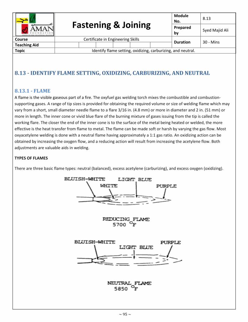
~ 95 ~
Fastening & Joining Module
No. 8.13
Prepared
by Syed Majid Ali
Course Certificate in Engineering Skills Duration 30 - Mins
Teaching Aid
Topic Identify flame setting, oxidizing, carburizing, and neutral.
8.13 - IDENTIFY FLAME SETTING, OXIDIZING, CARBURIZING, AND NEUTRAL
8.13.1 - FLAME
A flame is the visible gaseous part of a fire. The oxyfuel gas welding torch mixes the combustible and combustion-
supporting gases. A range of tip sizes is provided for obtaining the required volume or size of welding flame which may
vary from a short, small diameter needle flame to a flare 3/16 in. (4.8 mm) or more in diameter and 2 in. (51 mm) or
more in length. The inner cone or vivid blue flare of the burning mixture of gases issuing from the tip is called the
working flare. The closer the end of the inner cone is to the surface of the metal being heated or welded, the more
effective is the heat transfer from flame to metal. The flame can be made soft or harsh by varying the gas flow. Most
oxyacetylene welding is done with a neutral flame having approximately a 1:1 gas ratio. An oxidizing action can be
obtained by increasing the oxygen flow, and a reducing action will result from increasing the acetylene flow. Both
adjustments are valuable aids in welding.
TYPES OF FLAMES
There are three basic flame types: neutral (balanced), excess acetylene (carburizing), and excess oxygen (oxidizing).
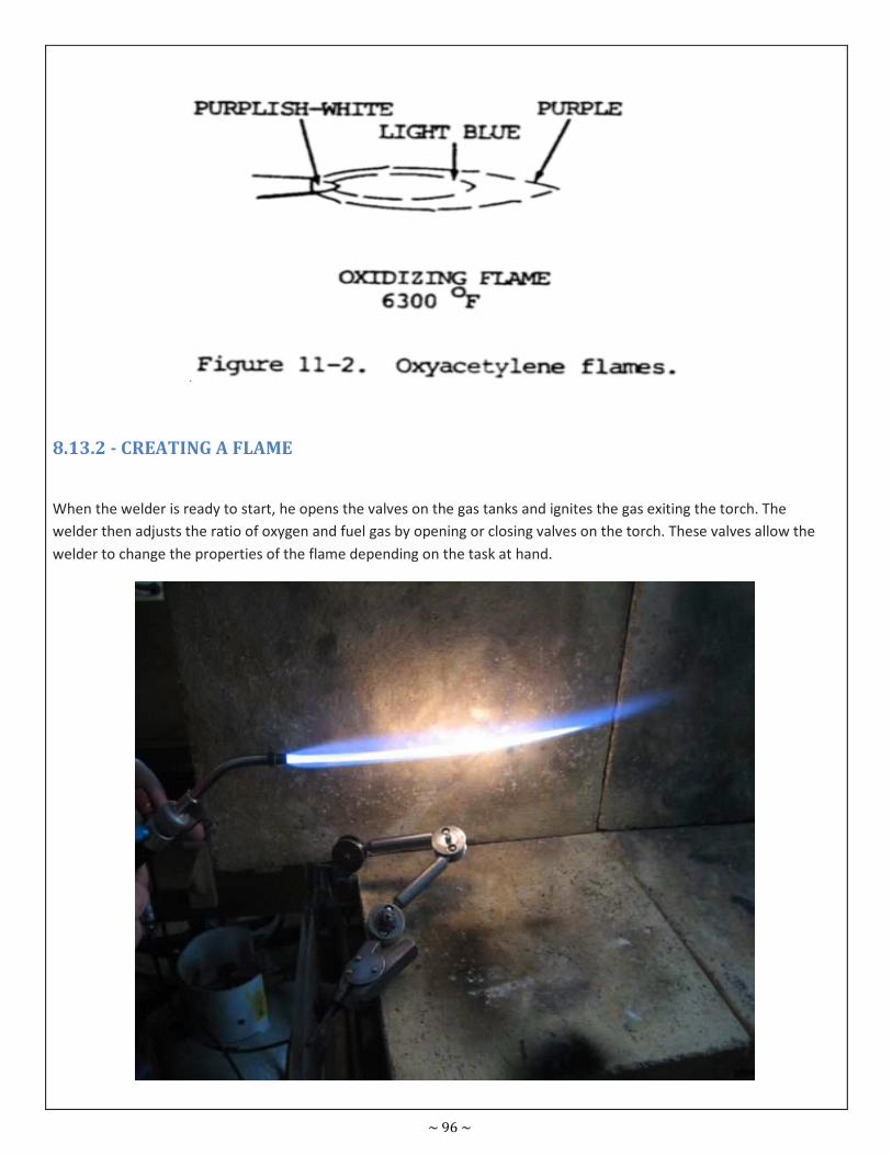
~ 96 ~
8.13.2 - CREATING A FLAME
When the welder is ready to start, he opens the valves on the gas tanks and ignites the gas exiting the torch. The
welder then adjusts the ratio of oxygen and fuel gas by opening or closing valves on the torch. These valves allow the
welder to change the properties of the flame depending on the task at hand.
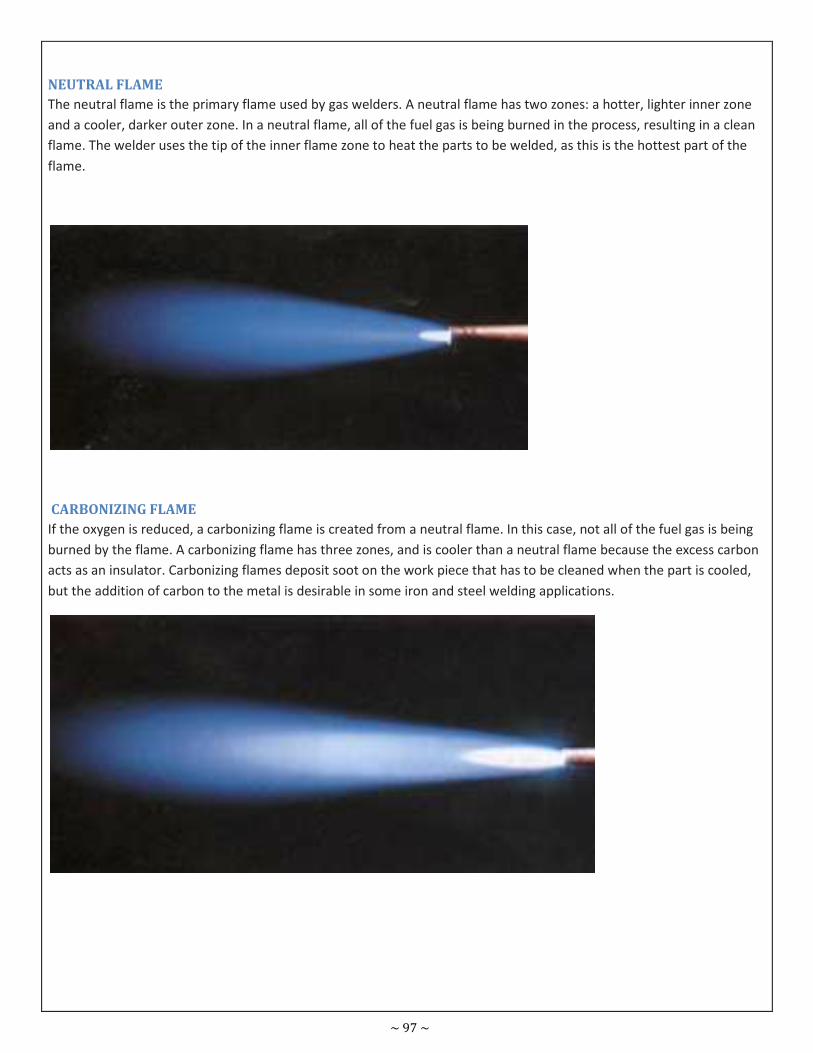
~ 97 ~
NEUTRAL FLAME
The neutral flame is the primary flame used by gas welders. A neutral flame has two zones: a hotter, lighter inner zone
and a cooler, darker outer zone. In a neutral flame, all of the fuel gas is being burned in the process, resulting in a clean
flame. The welder uses the tip of the inner flame zone to heat the parts to be welded, as this is the hottest part of the
flame.
CARBONIZING FLAME
If the oxygen is reduced, a carbonizing flame is created from a neutral flame. In this case, not all of the fuel gas is being
burned by the flame. A carbonizing flame has three zones, and is cooler than a neutral flame because the excess carbon
acts as an insulator. Carbonizing flames deposit soot on the work piece that has to be cleaned when the part is cooled,
but the addition of carbon to the metal is desirable in some iron and steel welding applications.
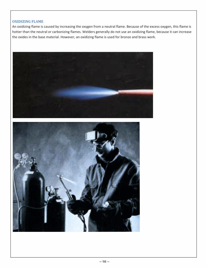
~ 98 ~
OXIDIZING FLAME
An oxidizing flame is caused by increasing the oxygen from a neutral flame. Because of the excess oxygen, this flame is
hotter than the neutral or carbonizing flames. Welders generally do not use an oxidizing flame, because it can increase
the oxides in the base material. However, an oxidizing flame is used for bronze and brass work.
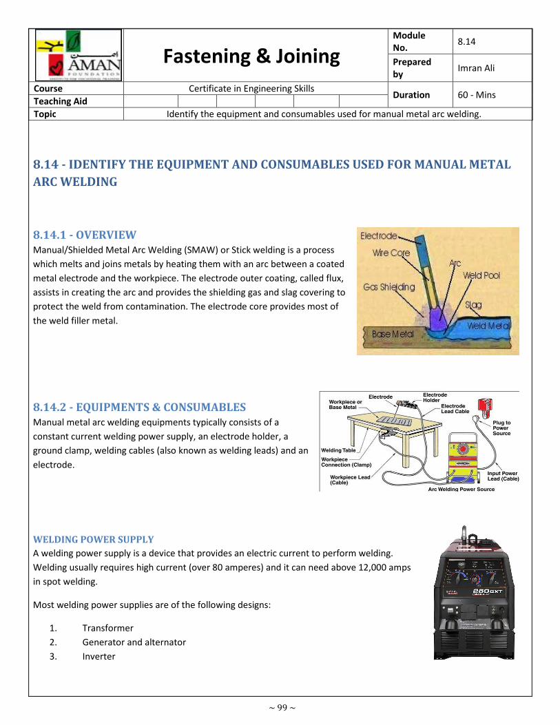
~ 99 ~
Fastening & Joining Module
No. 8.14
Prepared
by Imran Ali
Course Certificate in Engineering Skills Duration 60 - Mins
Teaching Aid
Topic Identify the equipment and consumables used for manual metal arc welding.
8.14 - IDENTIFY THE EQUIPMENT AND CONSUMABLES USED FOR MANUAL METAL
ARC WELDING
8.14.1 - OVERVIEW
Manual/Shielded Metal Arc Welding (SMAW) or Stick welding is a process
which melts and joins metals by heating them with an arc between a coated
metal electrode and the workpiece. The electrode outer coating, called flux,
assists in creating the arc and provides the shielding gas and slag covering to
protect the weld from contamination. The electrode core provides most of
the weld filler metal.
8.14.2 - EQUIPMENTS & CONSUMABLES
Manual metal arc welding equipments typically consists of a
constant current welding power supply, an electrode holder, a
ground clamp, welding cables (also known as welding leads) and an
electrode.
WELDING POWER SUPPLY
A welding power supply is a device that provides an electric current to perform welding.
Welding usually requires high current (over 80 amperes) and it can need above 12,000 amps
in spot welding.
Most welding power supplies are of the following designs:
1. Transformer
2. Generator and alternator
3. Inverter
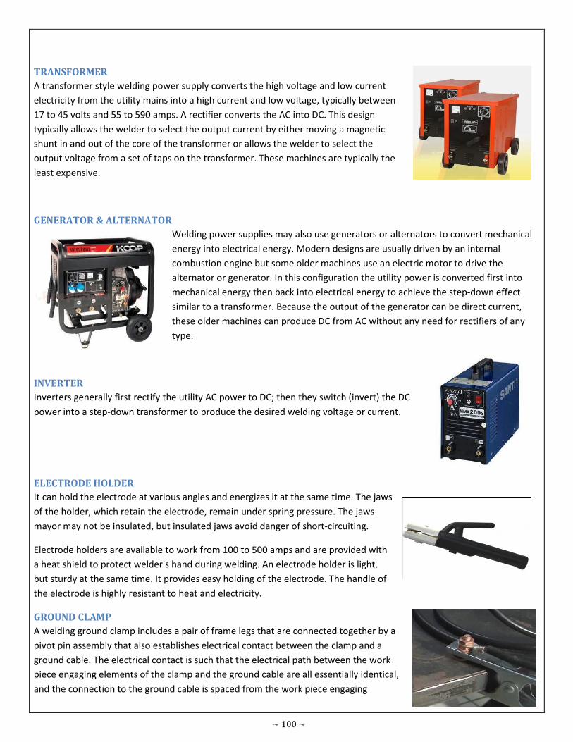
~ 100 ~
TRANSFORMER
A transformer style welding power supply converts the high voltage and low current
electricity from the utility mains into a high current and low voltage, typically between
17 to 45 volts and 55 to 590 amps. A rectifier converts the AC into DC. This design
typically allows the welder to select the output current by either moving a magnetic
shunt in and out of the core of the transformer or allows the welder to select the
output voltage from a set of taps on the transformer. These machines are typically the
least expensive.
GENERATOR & ALTERNATOR
Welding power supplies may also use generators or alternators to convert mechanical
energy into electrical energy. Modern designs are usually driven by an internal
combustion engine but some older machines use an electric motor to drive the
alternator or generator. In this configuration the utility power is converted first into
mechanical energy then back into electrical energy to achieve the step-down effect
similar to a transformer. Because the output of the generator can be direct current,
these older machines can produce DC from AC without any need for rectifiers of any
type.
INVERTER
Inverters generally first rectify the utility AC power to DC; then they switch (invert) the DC
power into a step-down transformer to produce the desired welding voltage or current.
ELECTRODE HOLDER
It can hold the electrode at various angles and energizes it at the same time. The jaws
of the holder, which retain the electrode, remain under spring pressure. The jaws
mayor may not be insulated, but insulated jaws avoid danger of short-circuiting.
Electrode holders are available to work from 100 to 500 amps and are provided with
a heat shield to protect welder's hand during welding. An electrode holder is light,
but sturdy at the same time. It provides easy holding of the electrode. The handle of
the electrode is highly resistant to heat and electricity.
GROUND CLAMP
A welding ground clamp includes a pair of frame legs that are connected together by a
pivot pin assembly that also establishes electrical contact between the clamp and a
ground cable. The electrical contact is such that the electrical path between the work
piece engaging elements of the clamp and the ground cable are all essentially identical,
and the connection to the ground cable is spaced from the work piece engaging
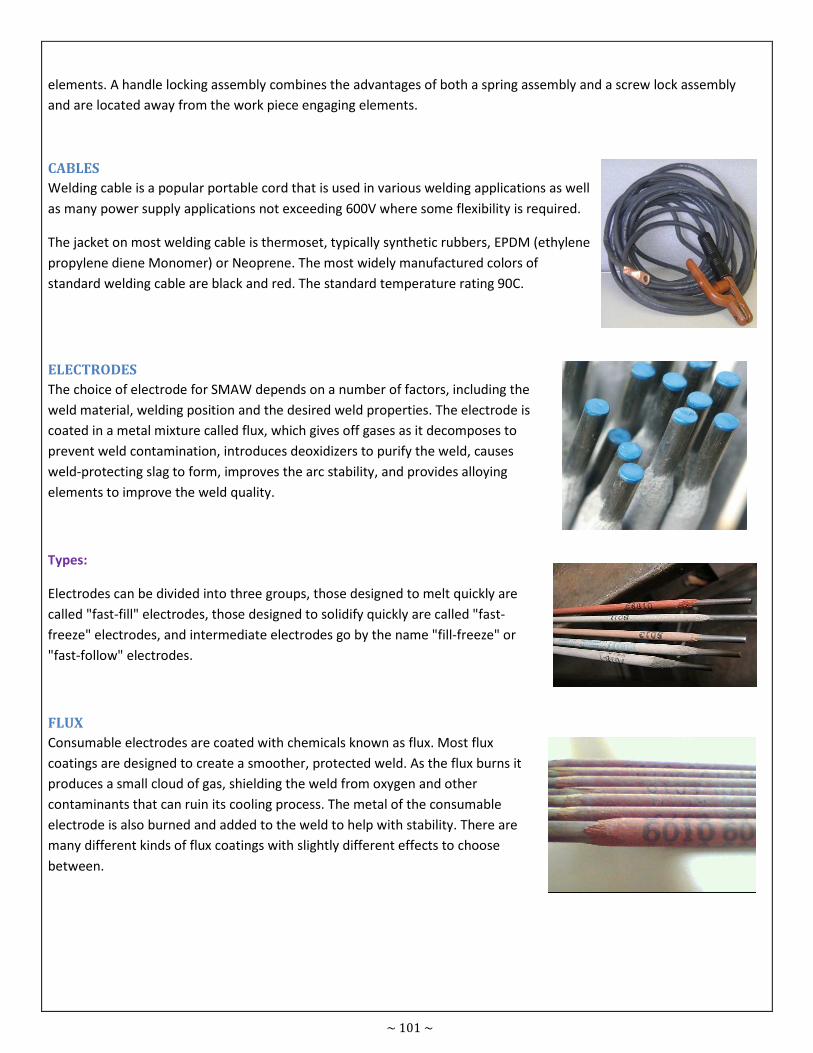
~ 101 ~
elements. A handle locking assembly combines the advantages of both a spring assembly and a screw lock assembly
and are located away from the work piece engaging elements.
CABLES
Welding cable is a popular portable cord that is used in various welding applications as well
as many power supply applications not exceeding 600V where some flexibility is required.
The jacket on most welding cable is thermoset, typically synthetic rubbers, EPDM (ethylene
propylene diene Monomer) or Neoprene. The most widely manufactured colors of
standard welding cable are black and red. The standard temperature rating 90C.
ELECTRODES
The choice of electrode for SMAW depends on a number of factors, including the
weld material, welding position and the desired weld properties. The electrode is
coated in a metal mixture called flux, which gives off gases as it decomposes to
prevent weld contamination, introduces deoxidizers to purify the weld, causes
weld-protecting slag to form, improves the arc stability, and provides alloying
elements to improve the weld quality.
Types:
Electrodes can be divided into three groups, those designed to melt quickly are
called "fast-fill" electrodes, those designed to solidify quickly are called "fast-
freeze" electrodes, and intermediate electrodes go by the name "fill-freeze" or
"fast-follow" electrodes.
FLUX
Consumable electrodes are coated with chemicals known as flux. Most flux
coatings are designed to create a smoother, protected weld. As the flux burns it
produces a small cloud of gas, shielding the weld from oxygen and other
contaminants that can ruin its cooling process. The metal of the consumable
electrode is also burned and added to the weld to help with stability. There are
many different kinds of flux coatings with slightly different effects to choose
between.
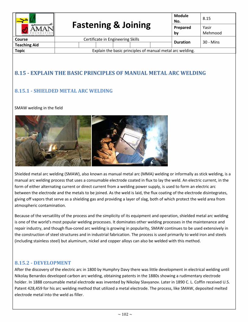
~ 102 ~
Fastening & Joining Module
No. 8.15
Prepared
by
Yasir
Mehmood
Course Certificate in Engineering Skills Duration 30 - Mins
Teaching Aid
Topic Explain the basic principles of manual metal arc welding.
8.15 - EXPLAIN THE BASIC PRINCIPLES OF MANUAL METAL ARC WELDING
8.15.1 - SHIELDED METAL ARC WELDING
SMAW welding in the field
Shielded metal arc welding (SMAW), also known as manual metal arc (MMA) welding or informally as stick welding, is a
manual arc welding process that uses a consumable electrode coated in flux to lay the weld. An electric current, in the
form of either alternating current or direct current from a welding power supply, is used to form an electric arc
between the electrode and the metals to be joined. As the weld is laid, the flux coating of the electrode disintegrates,
giving off vapors that serve as a shielding gas and providing a layer of slag, both of which protect the weld area from
atmospheric contamination.
Because of the versatility of the process and the simplicity of its equipment and operation, shielded metal arc welding
is one of the world's most popular welding processes. It dominates other welding processes in the maintenance and
repair industry, and though flux-cored arc welding is growing in popularity, SMAW continues to be used extensively in
the construction of steel structures and in industrial fabrication. The process is used primarily to weld iron and steels
(including stainless steel) but aluminum, nickel and copper alloys can also be welded with this method.
8.15.2 - DEVELOPMENT
After the discovery of the electric arc in 1800 by Humphry Davy there was little development in electrical welding until
Nikolay Benardos developed carbon arc welding, obtaining patents in the 1880s showing a rudimentary electrode
holder. In 1888 consumable metal electrode was invented by Nikolay Slavyanov. Later in 1890 C. L. Coffin received U.S.
Patent 428,459 for his arc welding method that utilized a metal electrode. The process, like SMAW, deposited melted
electrode metal into the weld as filler.
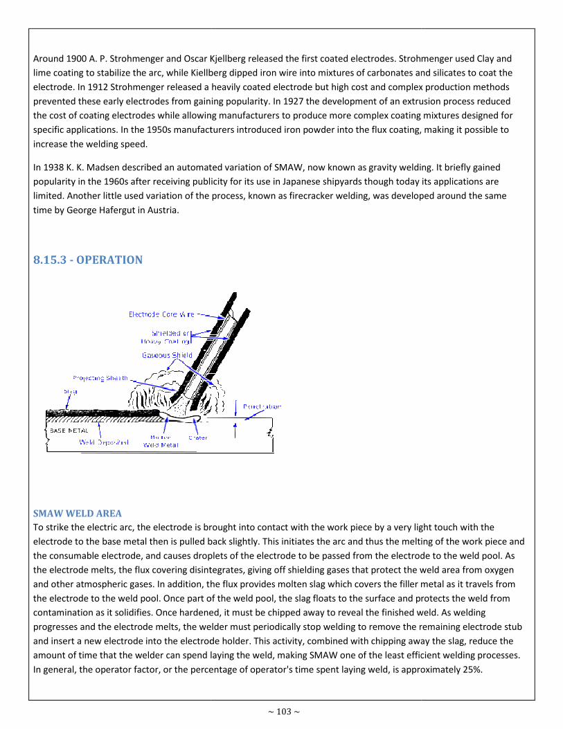
Around 1900 A. P. Strohmenger and Oscar Kjellberg
lime coating to stabilize the arc, while Kiellberg dipped
electrode. In 1912 Strohmenger released a heavily coated electrode but high cost and complex production methods
prevented these early electrodes from gaining po
the cost of coating electrodes while allowing manufacturers to produce more complex coating mixtures designed for
specific applications. In the 1950s manufacturers introduced iron powder into the flux coating, making it possible to
increase the welding speed.
In 1938 K. K. Madsen described an automated variation of SMAW, now known as
popularity in the 1960s after receiving publicity for its use in
limited. Another little used variation of the process, known as firecracker welding, was developed around the same
time by George Hafergut in Austria.
8.15.3 - OPERATION
SMAW WELD AREA
To strike the electric arc, the electrode is brought into contact with the work piece by a very light touch with the
electrode to the base metal then is pulled back slightly. This initiates the arc
the consumable electrode, and causes droplets of the electrode to be passed from the electrode to the
the electrode melts, the flux covering disintegrates, giving off shielding gases that protect the weld area from
and other atmospheric gases. In addition, the flux provides molten slag which covers the filler metal as it travels from
the electrode to the weld pool. Once part of the weld pool,
contamination as it solidifies. Once hardened, it must be chipped away to reveal the finished weld. As welding
progresses and the electrode melts, the welder must periodically stop welding to remov
and insert a new electrode into the electrode holder. This activity, combined with chipping away the slag, reduce the
amount of time that the welder can spend laying the weld, making SMAW one of the least efficient welding pr
In general, the operator factor, or the percentage of operator's time spent laying weld, is approximately 25%.
~ 103 ~
Oscar Kjellberg released the first coated electrodes. Strohmenger used
coating to stabilize the arc, while Kiellberg dipped iron wire into mixtures of carbonates and
electrode. In 1912 Strohmenger released a heavily coated electrode but high cost and complex production methods
prevented these early electrodes from gaining popularity. In 1927 the development of an extrusion
the cost of coating electrodes while allowing manufacturers to produce more complex coating mixtures designed for
applications. In the 1950s manufacturers introduced iron powder into the flux coating, making it possible to
In 1938 K. K. Madsen described an automated variation of SMAW, now known as gravity welding
popularity in the 1960s after receiving publicity for its use in Japanese shipyards though today its applications are
limited. Another little used variation of the process, known as firecracker welding, was developed around the same
, the electrode is brought into contact with the work piece by a very light touch with the
electrode to the base metal then is pulled back slightly. This initiates the arc and thus the melting of the work piece and
the consumable electrode, and causes droplets of the electrode to be passed from the electrode to the
the electrode melts, the flux covering disintegrates, giving off shielding gases that protect the weld area from
gases. In addition, the flux provides molten slag which covers the filler metal as it travels from
the electrode to the weld pool. Once part of the weld pool, the slag floats to the surface and protects the weld from
contamination as it solidifies. Once hardened, it must be chipped away to reveal the finished weld. As welding
progresses and the electrode melts, the welder must periodically stop welding to remove the remaining electrode stub
and insert a new electrode into the electrode holder. This activity, combined with chipping away the slag, reduce the
amount of time that the welder can spend laying the weld, making SMAW one of the least efficient welding pr
In general, the operator factor, or the percentage of operator's time spent laying weld, is approximately 25%.
released the first coated electrodes. Strohmenger used Clay and
and silicates to coat the
electrode. In 1912 Strohmenger released a heavily coated electrode but high cost and complex production methods
extrusion process reduced
the cost of coating electrodes while allowing manufacturers to produce more complex coating mixtures designed for
applications. In the 1950s manufacturers introduced iron powder into the flux coating, making it possible to
gravity welding. It briefly gained
shipyards though today its applications are
limited. Another little used variation of the process, known as firecracker welding, was developed around the same
, the electrode is brought into contact with the work piece by a very light touch with the
and thus the melting of the work piece and
the consumable electrode, and causes droplets of the electrode to be passed from the electrode to the weld pool. As
the electrode melts, the flux covering disintegrates, giving off shielding gases that protect the weld area from oxygen
gases. In addition, the flux provides molten slag which covers the filler metal as it travels from
the slag floats to the surface and protects the weld from
contamination as it solidifies. Once hardened, it must be chipped away to reveal the finished weld. As welding
e the remaining electrode stub
and insert a new electrode into the electrode holder. This activity, combined with chipping away the slag, reduce the
amount of time that the welder can spend laying the weld, making SMAW one of the least efficient welding processes.
In general, the operator factor, or the percentage of operator's time spent laying weld, is approximately 25%.
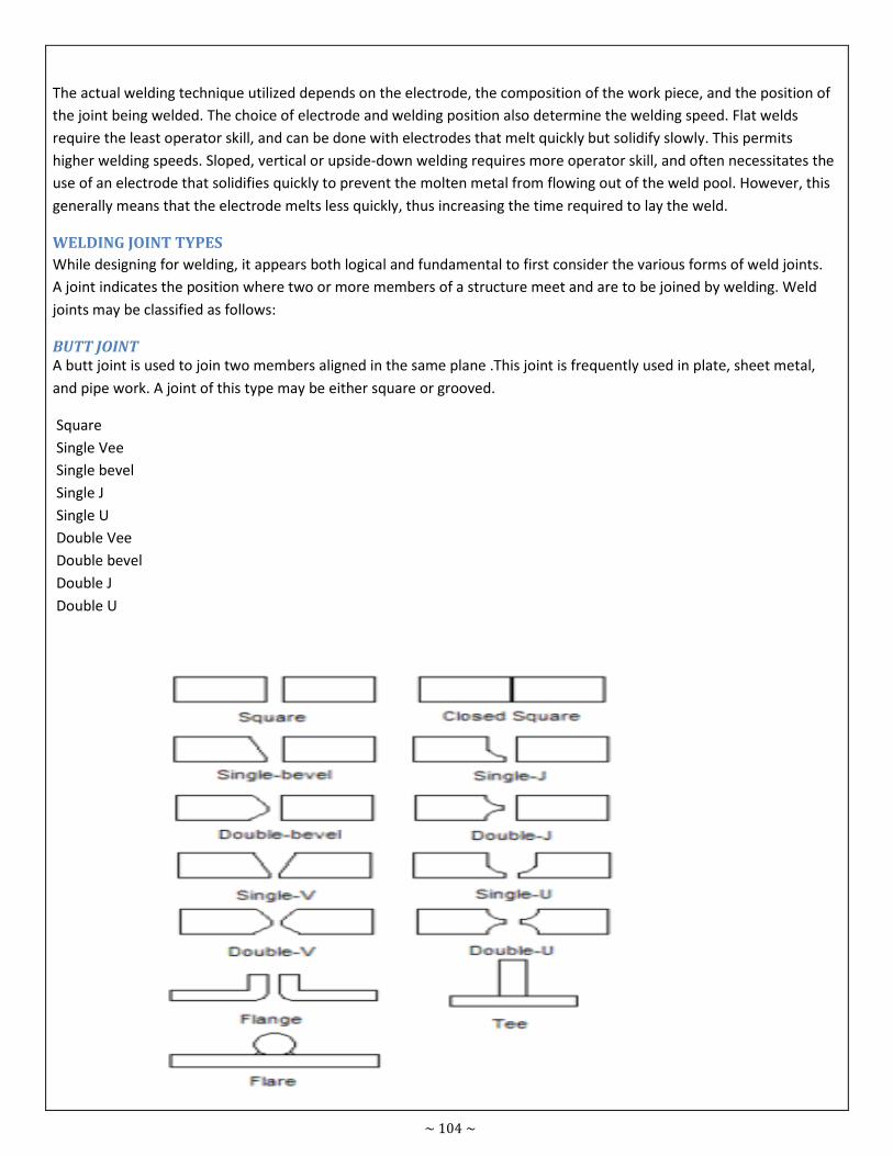
~ 104 ~
The actual welding technique utilized depends on the electrode, the composition of the work piece, and the position of
the joint being welded. The choice of electrode and welding position also determine the welding speed. Flat welds
require the least operator skill, and can be done with electrodes that melt quickly but solidify slowly. This permits
higher welding speeds. Sloped, vertical or upside-down welding requires more operator skill, and often necessitates the
use of an electrode that solidifies quickly to prevent the molten metal from flowing out of the weld pool. However, this
generally means that the electrode melts less quickly, thus increasing the time required to lay the weld.
WELDING JOINT TYPES
While designing for welding, it appears both logical and fundamental to first consider the various forms of weld joints.
A joint indicates the position where two or more members of a structure meet and are to be joined by welding. Weld
joints may be classified as follows:
BUTT JOINT
A butt joint is used to join two members aligned in the same plane .This joint is frequently used in plate, sheet metal,
and pipe work. A joint of this type may be either square or grooved.
Square
Single Vee
Single bevel
Single J
Single U
Double Vee
Double bevel
Double J
Double U
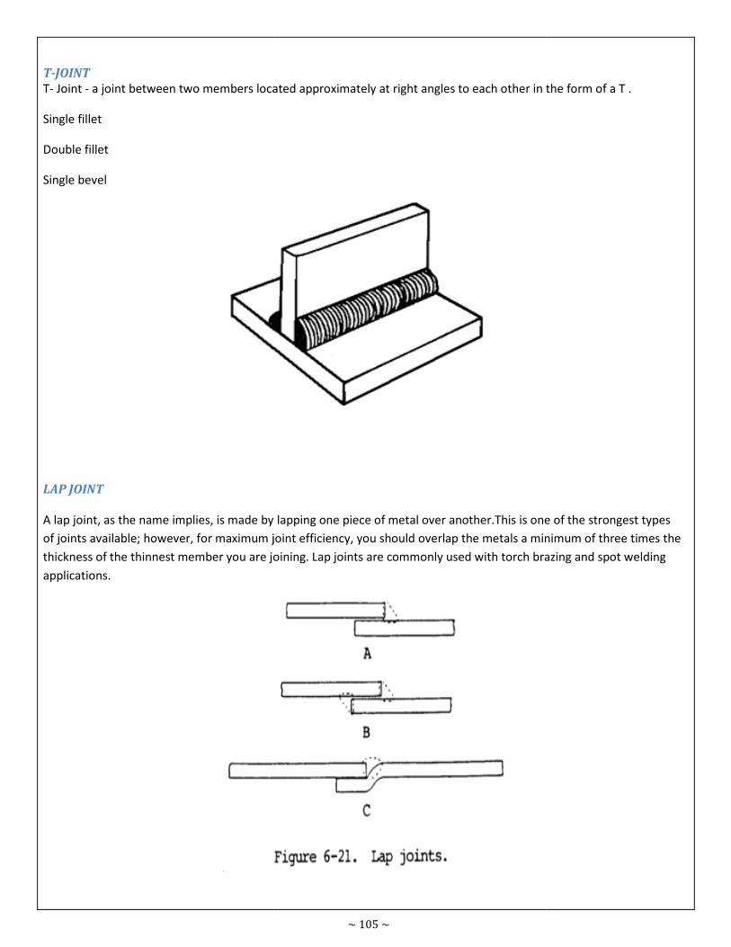
T-JOINT
T- Joint - a joint between two members located approximately at right angles to each other in the form of
Single fillet
Double fillet
Single bevel
LAP JOINT
A lap joint, as the name implies, is made by lapping one piece of metal over another.This is one of the strongest types
of joints available; however, for maximum joint efficiency, you should
thickness of the thinnest member you are joining. Lap joints are com
applications.
~ 105 ~
a joint between two members located approximately at right angles to each other in the form of
A lap joint, as the name implies, is made by lapping one piece of metal over another.This is one of the strongest types
of joints available; however, for maximum joint efficiency, you should overlap the metals a minimum of three times the
thickness of the thinnest member you are joining. Lap joints are commonly used with torch brazing and spot welding
a joint between two members located approximately at right angles to each other in the form of a T .
A lap joint, as the name implies, is made by lapping one piece of metal over another.This is one of the strongest types
overlap the metals a minimum of three times the
monly used with torch brazing and spot welding
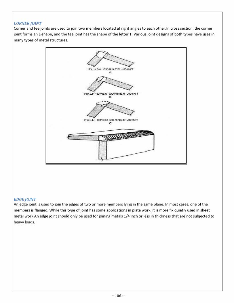
~ 106 ~
CORNER JOINT
Corner and tee joints are used to join two members located at right angles to each other.In cross section, the corner
joint forms an L-shape, and the tee joint has the shape of the letter T. Various joint designs of both types have uses in
many types of metal structures.
EDGE JOINT
An edge joint is used to join the edges of two or more members lying in the same plane. In most cases, one of the
members is flanged, While this type of joint has some applications in plate work, it is more fix quietly used in sheet
metal work An edge joint should only be used for joining metals 1/4 inch or less in thickness that are not subjected to
heavy loads.
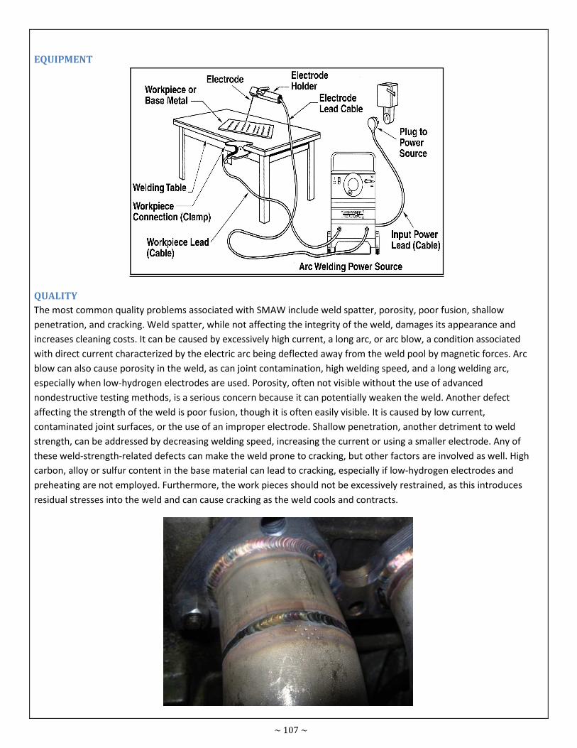
~ 107 ~
EQUIPMENT
QUALITY
The most common quality problems associated with SMAW include weld spatter, porosity, poor fusion, shallow
penetration, and cracking. Weld spatter, while not affecting the integrity of the weld, damages its appearance and
increases cleaning costs. It can be caused by excessively high current, a long arc, or arc blow, a condition associated
with direct current characterized by the electric arc being deflected away from the weld pool by magnetic forces. Arc
blow can also cause porosity in the weld, as can joint contamination, high welding speed, and a long welding arc,
especially when low-hydrogen electrodes are used. Porosity, often not visible without the use of advanced
nondestructive testing methods, is a serious concern because it can potentially weaken the weld. Another defect
affecting the strength of the weld is poor fusion, though it is often easily visible. It is caused by low current,
contaminated joint surfaces, or the use of an improper electrode. Shallow penetration, another detriment to weld
strength, can be addressed by decreasing welding speed, increasing the current or using a smaller electrode. Any of
these weld-strength-related defects can make the weld prone to cracking, but other factors are involved as well. High
carbon, alloy or sulfur content in the base material can lead to cracking, especially if low-hydrogen electrodes and
preheating are not employed. Furthermore, the work pieces should not be excessively restrained, as this introduces
residual stresses into the weld and can cause cracking as the weld cools and contracts.
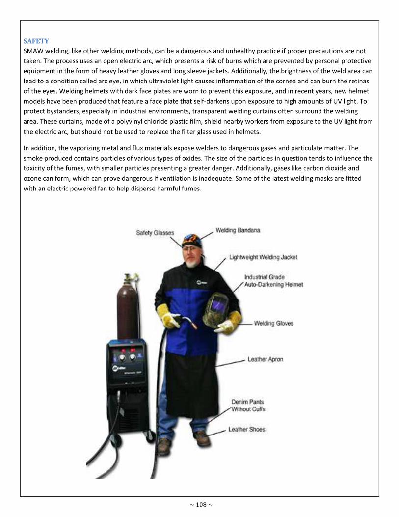
~ 108 ~
SAFETY
SMAW welding, like other welding methods, can be a dangerous and unhealthy practice if proper precautions are not
taken. The process uses an open electric arc, which presents a risk of burns which are prevented by personal protective
equipment in the form of heavy leather gloves and long sleeve jackets. Additionally, the brightness of the weld area can
lead to a condition called arc eye, in which ultraviolet light causes inflammation of the cornea and can burn the retinas
of the eyes. Welding helmets with dark face plates are worn to prevent this exposure, and in recent years, new helmet
models have been produced that feature a face plate that self-darkens upon exposure to high amounts of UV light. To
protect bystanders, especially in industrial environments, transparent welding curtains often surround the welding
area. These curtains, made of a polyvinyl chloride plastic film, shield nearby workers from exposure to the UV light from
the electric arc, but should not be used to replace the filter glass used in helmets.
In addition, the vaporizing metal and flux materials expose welders to dangerous gases and particulate matter. The
smoke produced contains particles of various types of oxides. The size of the particles in question tends to influence the
toxicity of the fumes, with smaller particles presenting a greater danger. Additionally, gases like carbon dioxide and
ozone can form, which can prove dangerous if ventilation is inadequate. Some of the latest welding masks are fitted
with an electric powered fan to help disperse harmful fumes.
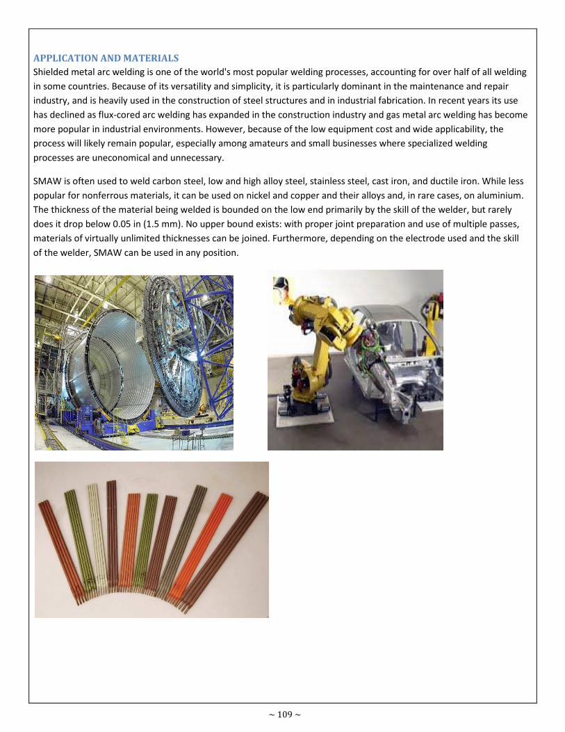
~ 109 ~
APPLICATION AND MATERIALS
Shielded metal arc welding is one of the world's most popular welding processes, accounting for over half of all welding
in some countries. Because of its versatility and simplicity, it is particularly dominant in the maintenance and repair
industry, and is heavily used in the construction of steel structures and in industrial fabrication. In recent years its use
has declined as flux-cored arc welding has expanded in the construction industry and gas metal arc welding has become
more popular in industrial environments. However, because of the low equipment cost and wide applicability, the
process will likely remain popular, especially among amateurs and small businesses where specialized welding
processes are uneconomical and unnecessary.
SMAW is often used to weld carbon steel, low and high alloy steel, stainless steel, cast iron, and ductile iron. While less
popular for nonferrous materials, it can be used on nickel and copper and their alloys and, in rare cases, on aluminium.
The thickness of the material being welded is bounded on the low end primarily by the skill of the welder, but rarely
does it drop below 0.05 in (1.5 mm). No upper bound exists: with proper joint preparation and use of multiple passes,
materials of virtually unlimited thicknesses can be joined. Furthermore, depending on the electrode used and the skill
of the welder, SMAW can be used in any position.
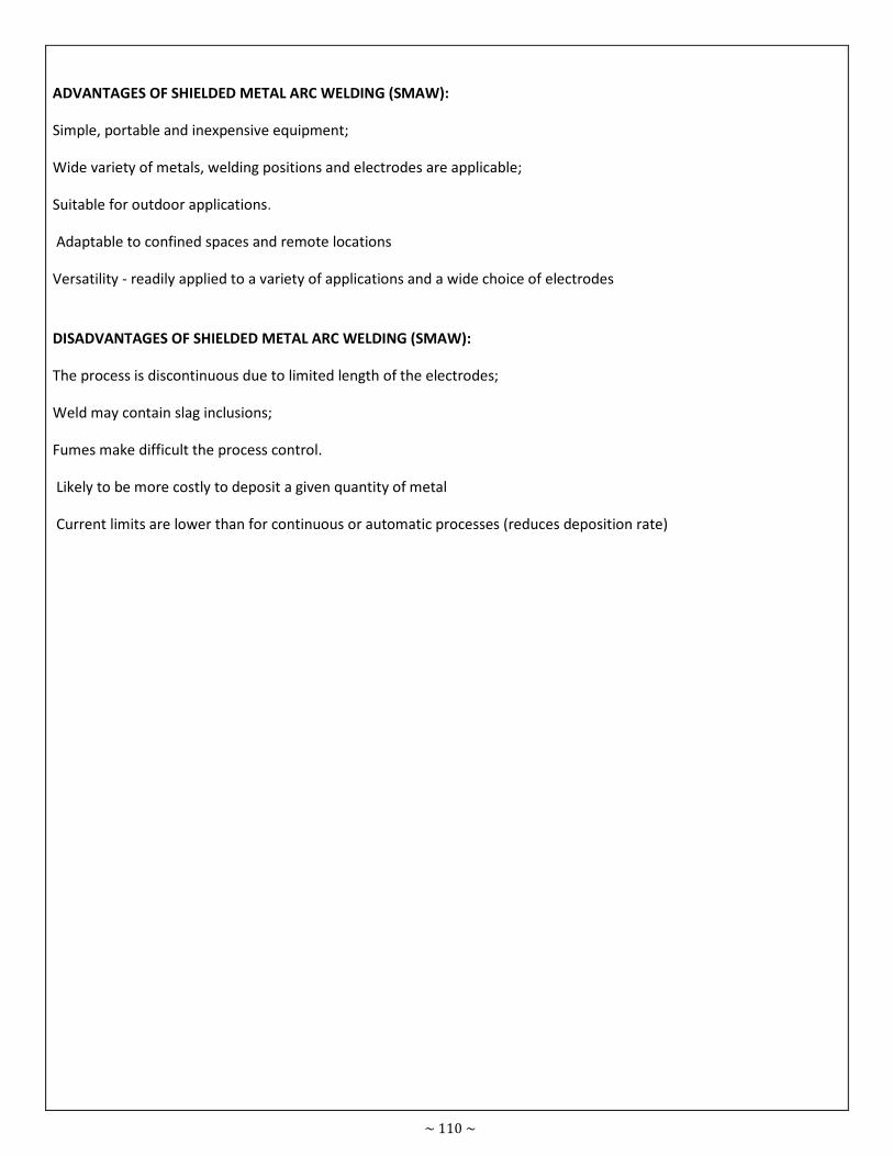
~ 110 ~
ADVANTAGES OF SHIELDED METAL ARC WELDING (SMAW):
Simple, portable and inexpensive equipment;
Wide variety of metals, welding positions and electrodes are applicable;
Suitable for outdoor applications.
Adaptable to confined spaces and remote locations
Versatility - readily applied to a variety of applications and a wide choice of electrodes
DISADVANTAGES OF SHIELDED METAL ARC WELDING (SMAW):
The process is discontinuous due to limited length of the electrodes;
Weld may contain slag inclusions;
Fumes make difficult the process control.
Likely to be more costly to deposit a given quantity of metal
Current limits are lower than for continuous or automatic processes (reduces deposition rate)
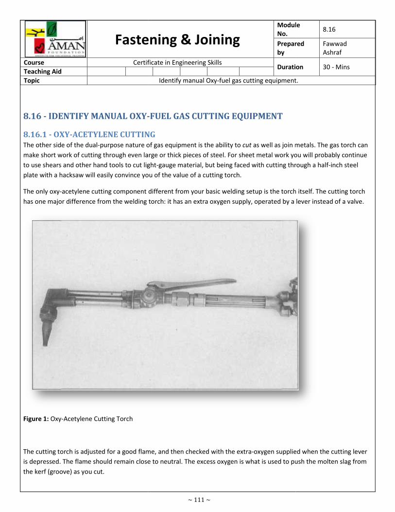
Fastening & Joining
Course Certificate in Engineering Skills
Teaching Aid
Topic
8.16 - IDENTIFY MANUAL OXY-
8.16.1 - OXY-ACETYLENE CUTTING
The other side of the dual-purpose nature of gas equipment is the ability to
make short work of cutting through even large or thick pieces of steel. For sheet metal work you will probably continue
to use shears and other hand tools to cut light
plate with a hacksaw will easily convince you of the value of a cutting torch.
The only oxy-acetylene cutting component different from your basic welding setup is the torch itself. The cutting torch
has one major difference from the welding torch: it has an extra oxygen supply,
Figure 1: Oxy-Acetylene Cutting Torch
The cutting torch is adjusted for a good flame, and then checked with the extra
is depressed. The flame should remain close to neutral. The excess oxygen is what is used to push the molten slag from
the kerf (groove) as you cut.
~ 111 ~
Fastening & Joining Module
No.
Prepared
by
Certificate in Engineering Skills Duration
Identify manual Oxy-fuel gas cutting equipment.
-FUEL GAS CUTTING EQUIPMENT
ACETYLENE CUTTING
purpose nature of gas equipment is the ability to cut as well as join metals. The gas torch can
short work of cutting through even large or thick pieces of steel. For sheet metal work you will probably continue
to use shears and other hand tools to cut light-gauge material, but being faced with cutting through a half
ill easily convince you of the value of a cutting torch.
acetylene cutting component different from your basic welding setup is the torch itself. The cutting torch
has one major difference from the welding torch: it has an extra oxygen supply, operated by a lever instead of a valve.
The cutting torch is adjusted for a good flame, and then checked with the extra-oxygen supplied when the cutting lever
remain close to neutral. The excess oxygen is what is used to push the molten slag from
Module 8.16
Prepared Fawwad
Ashraf
Duration 30 - Mins
fuel gas cutting equipment.
as well as join metals. The gas torch can
short work of cutting through even large or thick pieces of steel. For sheet metal work you will probably continue
gauge material, but being faced with cutting through a half-inch steel
acetylene cutting component different from your basic welding setup is the torch itself. The cutting torch
operated by a lever instead of a valve.
oxygen supplied when the cutting lever
remain close to neutral. The excess oxygen is what is used to push the molten slag from
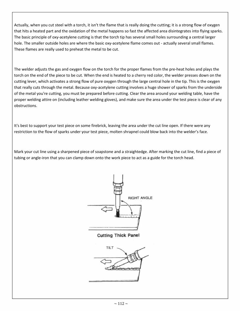
~ 112 ~
Actually, when you cut steel with a torch, it isn't the flame that is really doing the cutting; it is a strong flow of oxygen
that hits a heated part and the oxidation of the metal happens so fast the affected area disintegrates into flying sparks.
The basic principle of oxy-acetylene cutting is that the torch tip has several small holes surrounding a central larger
hole. The smaller outside holes are where the basic oxy-acetylene flame comes out - actually several small flames.
These flames are really used to preheat the metal to be cut.
The welder adjusts the gas and oxygen flow on the torch for the proper flames from the pre-heat holes and plays the
torch on the end of the piece to be cut. When the end is heated to a cherry red color, the welder presses down on the
cutting lever, which activates a strong flow of pure oxygen through the large central hole in the tip. This is the oxygen
that really cuts through the metal. Because oxy-acetylene cutting involves a huge shower of sparks from the underside
of the metal you're cutting, you must be prepared before cutting. Clear the area around your welding table, have the
proper welding attire on (including leather welding gloves), and make sure the area under the test piece is clear of any
obstructions.
It's best to support your test piece on some firebrick, leaving the area under the cut line open. If there were any
restriction to the flow of sparks under your test piece, molten shrapnel could blow back into the welder’s face.
Mark your cut line using a sharpened piece of soapstone and a straightedge. After marking the cut line, find a piece of
tubing or angle-iron that you can clamp down onto the work piece to act as a guide for the torch head.
~ 113 ~
The cutting torch should be held more nearly vertical to the work when cutting heavier metals, and angled back when
cutting thinner material like exhaust pipe or sheet metal. Use scraps steel tubing or angle as a brace to guide the torch
for steadier cutting.
8.16.2 - SAFETY
1. Eye protection
2. Fuel leakage
3. Safety with cylinders
4. Chemical exposure
5. Flashback
• Wear personal protective equipment.
• Wear welding gloves, helmet, leather apron, welding chaps, leather shoes, welding goggles, and other personal
protective equipment to help prevent weld burns and injury.
• Make sure the welding goggles or face shield have at least a No. 4 filter lens.
• Do not wear clothing made of synthetic fibers while welding.
• Fasten cylinders securely.
• Do not handle cylinders roughly.
• Chain cylinders in an upright position to a wall or cart.
• When regulators are not on cylinders, keep safety caps in place. Caps will prevent damage to cylinder valves.
• Never use oil on welding equipment. Oil and grease may ignite spontaneously, when in contact with oxygen.
• Open cylinder valves correctly. Open the valve on the acetylene cylinder no more than three-fourths of a turn
so it can be closed quickly in case of emergency. Open the valve on the oxygen tank fully. While welding or
cutting, leave the valve wrench in position.
• Keep the tip pointed away from your body.
• Do not saturate your clothing with oxygen or acetylene. Before and while lighting the flame, keep the tip
pointed away from your body.
• Light the flame with an approved lighter. Using matches to light the torch brings fingers too close to the tip.
• Set the operating pressure carefully.
• Never use acetylene at a pressure over 15 psi. Follow the manufacturer's recommendations for the correct
operating pressures for the metal being welded and for the tip size being used.
• Do not smoke or allow anyone else to smoke near the oxy-fuel gas welder. If fuel gas were to leak from the
unit, smoking could provide ignition and cause a fire or an explosion.
• Treat the flame with respect. Keep the flame and heat away from the cylinder, hoses, and people. Never lay
down a lighted torch.
• Be sure the flame is out before laying down the torch. Never walk around with a lighted torch.
• Control flashbacks and backfires.
• Make certain that reverse flow-check valves and flash arrestors are installed on the oxygen and acetylene lines.
• Do not leave the work area until the cylinder valves are closed.
• Be sure the cylinder valves are closed and pressure is relieved from the hoses before you leave the work area.
• Never stand in front of a regulator while you are opening a tank valve.
• Do not weld or cut on containers that have held flammable materials.
• Remove regulators and replace protective caps before transporting cylinders.
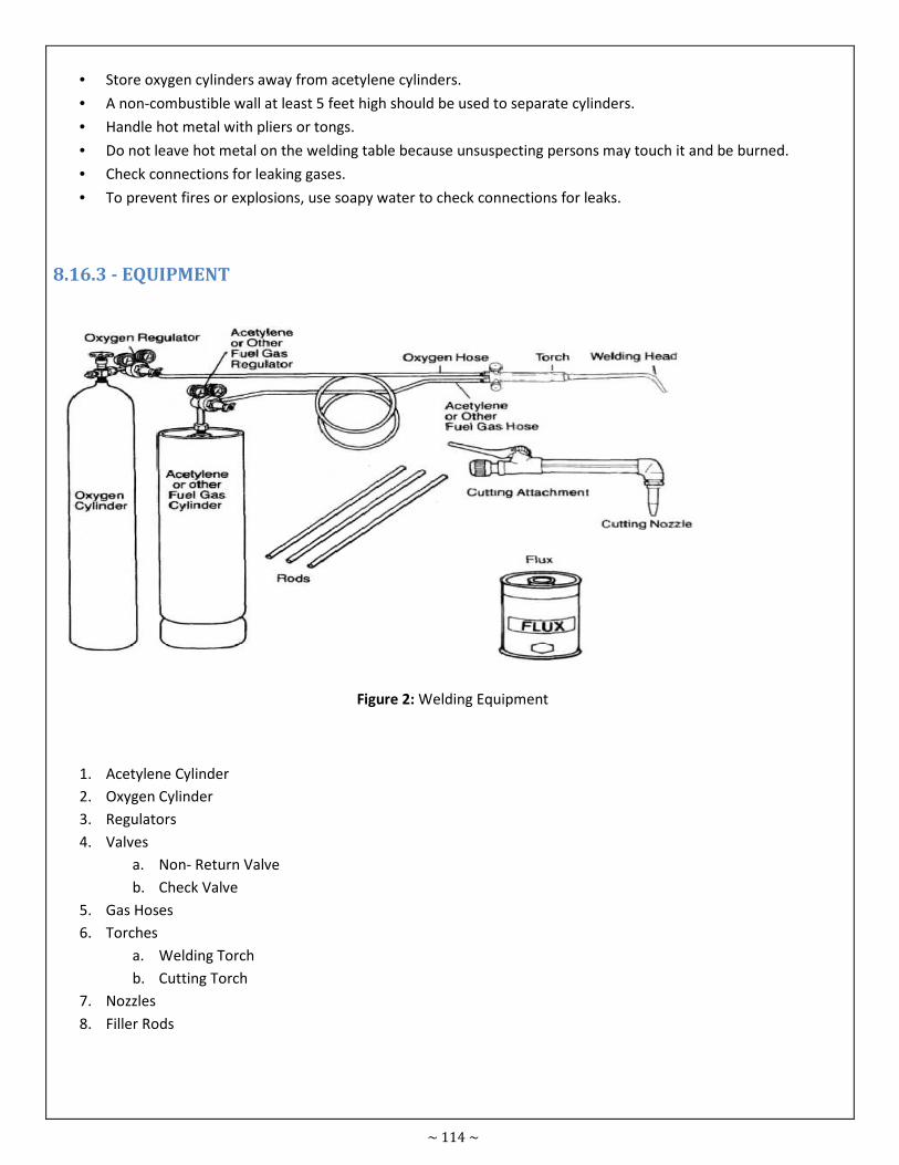
~ 114 ~
• Store oxygen cylinders away from acetylene cylinders.
• A non-combustible wall at least 5 feet high should be used to separate cylinders.
• Handle hot metal with pliers or tongs.
• Do not leave hot metal on the welding table because unsuspecting persons may touch it and be burned.
• Check connections for leaking gases.
• To prevent fires or explosions, use soapy water to check connections for leaks.
8.16.3 - EQUIPMENT
Figure 2: Welding Equipment
1. Acetylene Cylinder
2. Oxygen Cylinder
3. Regulators
4. Valves
a. Non- Return Valve
b. Check Valve
5. Gas Hoses
6. Torches
a. Welding Torch
b. Cutting Torch
7. Nozzles
8. Filler Rods
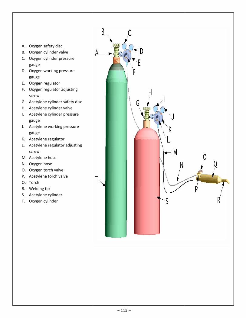
A. Oxygen safety disc
B. Oxygen cylinder valve
C. Oxygen cylinder pressure
gauge
D. Oxygen working pressure
gauge
E. Oxygen regulator
F. Oxygen regulator adjusting
screw
G. Acetylene cylinder safety disc
H. Acetylene cylinder valve
I. Acetylene cylinder pressure
gauge
J. Acetylene working pressure
gauge
K. Acetylene regulator
L. Acetylene regulator adjusting
screw
M. Acetylene hose
N. Oxygen hose
O. Oxygen torch valve
P. Acetylene torch valve
Q. Torch
R. Welding tip
S. Acetylene cylinder
T. Oxygen cylinder
~ 115 ~
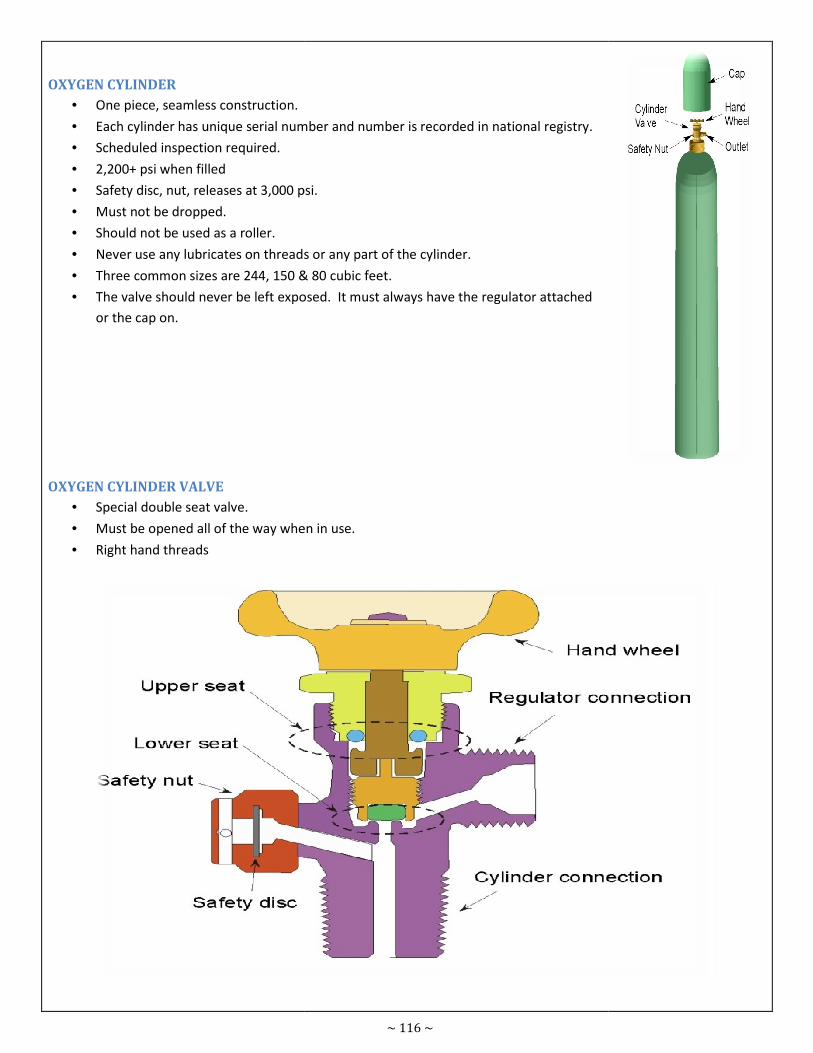
OXYGEN CYLINDER
• One piece, seamless construction.
• Each cylinder has unique serial number and number is recorded in national registry.
• Scheduled inspection required.
• 2,200+ psi when filled
• Safety disc, nut, releases at 3,000 psi.
• Must not be dropped.
• Should not be used as a roller.
• Never use any lubricates on threads or any part of the cylinder.
• Three common sizes are 244, 150 & 80 cubic feet.
• The valve should never be left exposed. It must always have the regulator attached
or the cap on.
OXYGEN CYLINDER VALVE
• Special double seat valve.
• Must be opened all of the way when in use.
• Right hand threads
~ 116 ~
Each cylinder has unique serial number and number is recorded in national registry.
Safety disc, nut, releases at 3,000 psi.
Never use any lubricates on threads or any part of the cylinder.
Three common sizes are 244, 150 & 80 cubic feet.
The valve should never be left exposed. It must always have the regulator attached
Must be opened all of the way when in use.
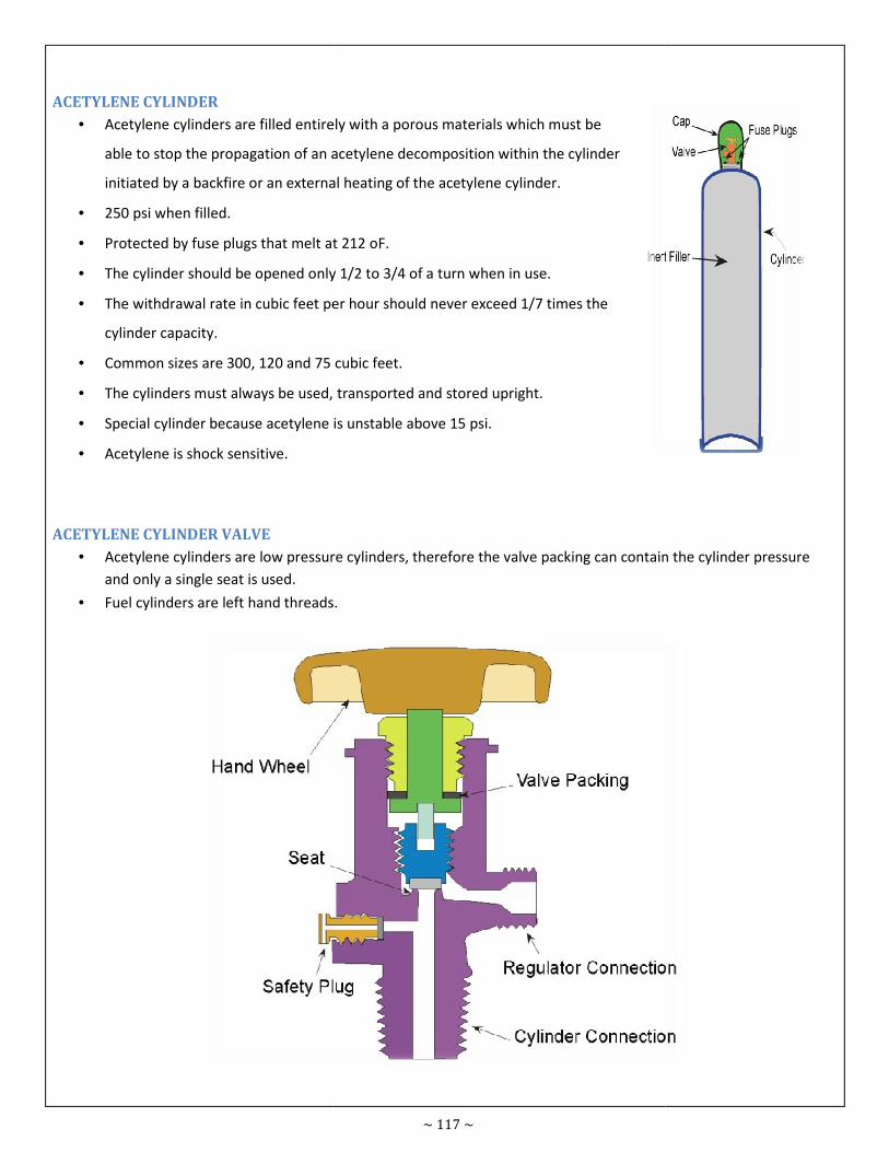
ACETYLENE CYLINDER
• Acetylene cylinders are filled entirely with a porous materials which must be
able to stop the propagation of an acetylene decomposition
initiated by a backfire or an external heating of the acetylene cylinder.
• 250 psi when filled.
• Protected by fuse plugs that melt at 212 oF.
• The cylinder should be opened only 1/2 to 3/4 of a turn when in use.
• The withdrawal rate in cubic feet per hour should never exceed 1/7 times the
cylinder capacity.
• Common sizes are 300, 120 and 75 cubic feet.
• The cylinders must always be used, transported and stored upright.
• Special cylinder because acetylene is unstable above 15 psi.
• Acetylene is shock sensitive.
ACETYLENE CYLINDER VALVE
• Acetylene cylinders are low pressure cylinders, therefore the valve packing can contain the cylinder pressure
and only a single seat is used.
• Fuel cylinders are left hand threads.
~ 117 ~
Acetylene cylinders are filled entirely with a porous materials which must be
able to stop the propagation of an acetylene decomposition within the cylinder
initiated by a backfire or an external heating of the acetylene cylinder.
Protected by fuse plugs that melt at 212 oF.
The cylinder should be opened only 1/2 to 3/4 of a turn when in use.
c feet per hour should never exceed 1/7 times the
Common sizes are 300, 120 and 75 cubic feet.
The cylinders must always be used, transported and stored upright.
Special cylinder because acetylene is unstable above 15 psi.
Acetylene cylinders are low pressure cylinders, therefore the valve packing can contain the cylinder pressure
Fuel cylinders are left hand threads.
Acetylene cylinders are low pressure cylinders, therefore the valve packing can contain the cylinder pressure
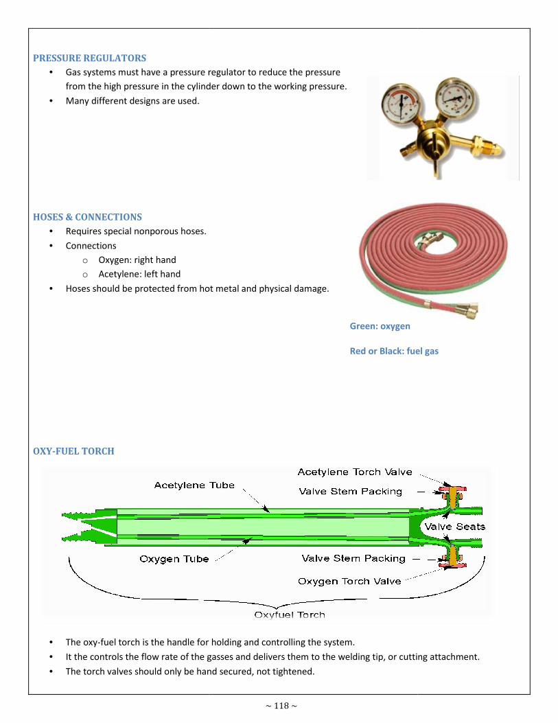
PRESSURE REGULATORS
• Gas systems must have a pressure regulator to reduce the pressure
from the high pressure in the cylinder down to the working pressure.
• Many different designs are used.
HOSES & CONNECTIONS
• Requires special nonporous hoses.
• Connections
o Oxygen: right hand
o Acetylene: left hand
• Hoses should be protected from hot metal and physical damage.
OXY-FUEL TORCH
• The oxy-fuel torch is the handle for holding and controlling the system.
• It the controls the flow rate of the gasses and delivers them to the welding tip, or cutting attachment.
• The torch valves should only be hand secured, not tightened.
~ 118 ~
s must have a pressure regulator to reduce the pressure
from the high pressure in the cylinder down to the working pressure.
Hoses should be protected from hot metal and physical damage.
fuel torch is the handle for holding and controlling the system.
gasses and delivers them to the welding tip, or cutting attachment.
The torch valves should only be hand secured, not tightened.
Green: oxygen
Red or Black: fuel gas
gasses and delivers them to the welding tip, or cutting attachment.
Red or Black: fuel gas
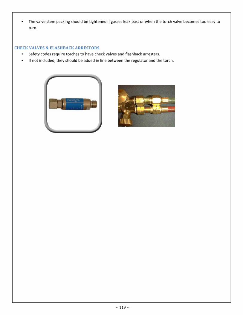
~ 119 ~
• The valve stem packing should be tightened if gasses leak past or when the torch valve becomes too easy to
turn.
CHECK VALVES & FLASHBACK ARRESTORS
• Safety codes require torches to have check valves and flashback arresters.
• If not included, they should be added in line between the regulator and the torch.
~ 120 ~
Fastening & Joining Module
No. 8.17
Prepared
by
Fawwad
Ashraf
Course Certificate in Engineering Skills Duration 30 - Mins
Teaching Aid
Topic Identify gases used for manual oxy-fuel gas cutting.
8.17 - IDENTIFY GASES USED FOR MANUAL OXY-FUEL GAS CUTTING
When gasses are used in other types of welding, they are usually of the inert kind, like argon, CO2 or helium, which are
involved in the welding process only to keep the molten weld puddle clear of impurities from the air during formation.
In oxy-acetylene welding/cutting, however, the gases are what make the flame itself. Acetylene gas is quite flammable,
and combined with oxygen, which by itself does not burn but speeds up the oxidation or burning of any other fuel,
makes one of the hottest possible gas flames (5600-6300° F),suitable for the rapid welding, cutting or heating of most
ferrous and non-ferrous materials. Although all compressed gasses pose some shop hazards because of the pressure
inside the bottles, oxygen and acetylene are considerably more dangerous to work around, and require much more
caution and close attention to safety rules.
8.17.1 - OXYGEN
Oxygen, while not exactly flammable by itself, is the gas necessary both for us to breathe and for any type of
combustion to take place. Combustion is really nothing more than very rapid oxidation, and if pure oxygen is directed
at something flammable, a fire can start very easily. Some inexperienced welders have been known to dust off their
work clothes with their unlit gas torch, but the extra oxygen that gets into their clothes can make it so flammable that
any tiny spark could start the clothes on fire. Likewise, oxygen gas must be kept away from things like oily rags or any
petroleum products. Oxygen as used in welding equipment is generally stored in high-pressure, 1/4-inch-thick-walled
steel cylinders s2200 psi. While oxygen may be important for our lungs to work, it can still be dangerous if too much is
introduced to the bloodstream. For this reason, oxygen gas should be kept away from open cuts such as you might
have on your hands.
8.17.2 - ACETYLENE
Acetylene gas on the other hand is flammable to the point of being explosive and is also mildly poisonous, causing
nausea and headaches if you breathe much of it.
Pressure in the acetylene gas cylinder is much less than with oxygen, at 250-325 psi, but the construction of the
cylinder is different. Acetylene cylinders are shorter and fatter than oxygen bottles, and are constructed in two halves.
Because acetylene is unstable at high pressures, the only way to get sufficient quantities into the standard bottle is to
dissolve the acetylene in another medium. In welding tanks, the two halves are filled with an asbestos/cement mixture
and then welded together. After baking, the material forms a honeycomb inside the tank.
Liquid acetone is put into the tank because it will absorb 25 times its own volume in acetylene gas, thus stabilizing the
acetylene.

~ 121 ~
8.17.3 - STORAGE
Because of the differences in chemical action and storage of oxygen and acetylene, there must be no mix-ups between
the two. For this reason, the tanks are made in different proportions and different colors; the acetylene bottle has only
left-hand threads, and the hoses for each bottle are different, i.e. red hose for acetylene, green hose for oxygen.