fastening elements - overview
TRANSCRIPT
554 ®
556
558
559
561
564
564
568
570
557
558
560
561
563
566
568
571
557
559
560
562
563
566
569
571
558
559
560
562
564
567
570
572
565565
567
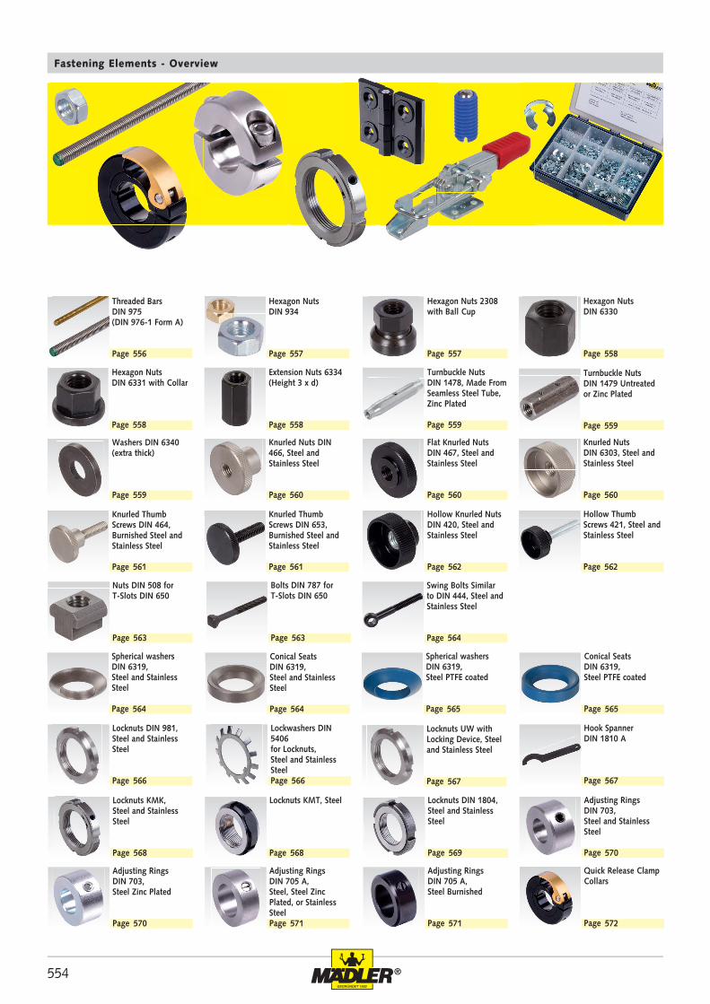
Fastening Elements - Overview
Threaded Bars DIN 975 (DIN 976-1 Form A)
Page
Hexagon Nuts DIN 6331 with Collar
Page
Washers DIN 6340 (extra thick)
Page
Knurled Thumb Screws DIN 464, Burnished Steel and Stainless Steel
Page
Swing Bolts Similar to DIN 444, Steel and Stainless Steel
Page
Conical Seats DIN 6319,Steel and Stainless Steel
Page
Locknuts KMK, Steel and Stainless Steel
Page
Adjusting RingsDIN 703, Steel Zinc Plated
Page
Hexagon Nuts DIN 934
Page
Extension Nuts 6334 (Height 3 x d)
Page
Knurled Nuts DIN 466, Steel and Stainless Steel
Page
Knurled Thumb Screws DIN 653, Burnished Steel and Stainless Steel
Page
Nuts DIN 508 for T-Slots DIN 650
Page
Locknuts DIN 981, Steel and Stainless Steel
Page
Locknuts KMT, Steel
Page
Adjusting RingsDIN 705 A, Steel, Steel Zinc Plated, or Stainless SteelPage
Hexagon Nuts 2308 with Ball Cup
Page
Turnbuckle Nuts DIN 1478, Made From Seamless Steel Tube, Zinc Plated
Page
Flat Knurled Nuts DIN 467, Steel and Stainless Steel
Page
Hollow Knurled Nuts DIN 420, Steel and Stainless Steel
Page
Bolts DIN 787 for T-Slots DIN 650
Page
Lockwashers DIN 5406for Locknuts,Steel and Stainless SteelPage
Locknuts DIN 1804, Steel and Stainless Steel
Page
Adjusting Rings DIN 705 A,Steel Burnished
Page
Hexagon Nuts DIN 6330
Page
Turnbuckle Nuts DIN 1479 Untreated or Zinc Plated
Page
Knurled Nuts DIN 6303, Steel and Stainless Steel
Page
Hollow Thumb Screws 421, Steel and Stainless Steel
Page
Spherical washers DIN 6319,Steel and Stainless Steel
Page
Hook SpannerDIN 1810 A
Page
Adjusting RingsDIN 703, Steel and Stainless Steel
Page
Quick Release Clamp Collars
Page
Conical Seats DIN 6319,Steel PTFE coated
Page
Spherical washers DIN 6319,Steel PTFE coated
Page
Locknuts UW with Locking Device, Steel and Stainless Steel
Page
FG
l1
l 2
FR
FA
- FR
555®
577 578 579
583
586
589
591
594
596
599
601
603
581 582
584
586
589
592
595
597
599
602
582
584
587
590
593
596
598
600
602
580
583
586
587
590
593
596
598
601
604
572 573 575 576
588
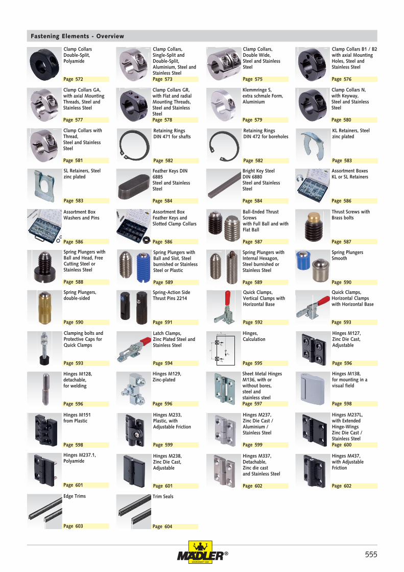
Fastening Elements - Overview
Clamp Collars GA,with axial Mounting Threads, Steel and Stainless Steel
Page
Clamp Collars with Thread, Steel and Stainless Steel
Page
SL Retainers, Steel zinc plated
Page
Assortment BoxWashers and Pins
Page
Spring Plungers with Ball and Slot, Steel burnished or Stainless Steel or Plastic
Page
Spring-Action Side Thrust Pins 2214
Page
Latch Clamps, Zinc Plated Steel and Stainless Steel
Page
Hinges M129, Zinc-plated
Page
Hinges M233, Plastic, with Adjustable Friction
Page
Hinges M238, Zinc Die Cast, Adjustable
Page
Edge Trims
Page
Clamp Collars GR,with Flat and radial Mounting Threads, Steel and Stainless SteelPage
Retaining Rings DIN 471 for shafts
Page
Feather Keys DIN 6885 Steel and Stainless Steel
Page
Assortment BoxFeather Keys and Slotted Clamp Collars
Page
Spring Plungers with Internal Hexagon, Steel burnished or Stainless Steel
Page
Quick Clamps, Vertical Clamps with Horizontal Base
Page
Hinges, Calculation
Page
Sheet Metal Hinges M136, with or without bores, steel andstainless steelPage
Hinges M237, Zinc Die Cast / Aluminium / Stainless Steel
Page
Hinges M337, Detachable, Zinc die castand Stainless Steel
Page
Klemmringe S, extra schmale Form,Aluminium
Page
Retaining Rings DIN 472 for boreholes
Page
Bright Key Steel DIN 6880 Steel and Stainless Steel
Page
Ball-Ended Thrust Screws with Full Ball and withFlat Ball
Page
Spring Plungers Smooth
Page
Quick Clamps, Horizontal Clamps with Horizontal Base
Page
Hinges M127, Zinc Die Cast, Adjustable
Page
Hinges M138, for mounting in a visual field
Page
Hinges M237L, with Extended Hinge-WingsZinc Die Cast / Stainless SteelPage
Hinges M437, with Adjustable Friction
Page
Clamp Collars N,with Keyway, Steel and Stainless Steel
Page
KL Retainers, Steel zinc plated
Page
Assortment BoxesKL or SL Retainers
Page
Thrust Screws with Brass bolts
Page
Spring Plungers, double-sided
Page
Clamping bolts and Protective Caps for Quick Clamps
Page
Hinges M128, detachable, for welding
Page
Hinges M151 from Plastic
Page
Hinges M237.1, Polyamide
Page
Trim Seals
Page
Clamp Collars Double-Split, Polyamide
Page
Clamp Collars,Single-Split and Double-Split, Aluminium, Steel and Stainless SteelPage
Clamp Collars, Double Wide,Steel and Stainless Steel
Page
Clamp Collars B1 / B2 with axial Mounting Holes, Steel and Stainless Steel
Page
Spring Plungers with Ball and Head, Free Cutting Steel or Stainless Steel
Page
556 ®
650 708 00 M8 x 1 1 31,9650 710 00 M10 x 1 1 50650 712 00 M12 x 1,5 1,5 72,5650 716 00 M16 x 1,5 1,5 133650 720 00 M20 x 1,5 1,5 208650 724 00 M24 x 1,5 1,5 300650 730 00 M30 x 2 2 475
650 990 03 M3 0,5 4,4650 990 04 M4 0,7 7,8650 990 05 M5 0,8 12,4650 990 06 M6 1 17,7650 990 08 M8 1,25 31,9650 990 10 M10 1,5 50650 990 12 M12 1,75 72,5650 990 16 M16 2 133650 990 20 M20 2,5 208650 990 24 M24 3 300650 990 30 M30 3,5 475
650 403 00 M3 0,5 4,8650 404 00 M4 0,7 8,5650 405 00 M5 0,8 13,4650 406 00 M6 1 19,2650 408 00 M8 1,25 34,5650 410 00 M10 1,5 54,2650 412 00 M12 1,75 78,5650 416 00 M16 2 144650 420 00 M20 2,5 226
651 004 00 -- M4 0,7 0,08 --651 005 00 -- M5 0,8 0,12 --651 006 00 -- M6 1 0,18 -- 651 008 00 651 208 00 M8 1,25 0,32 0,64 651 010 00 651 210 00 M10 1,5 0,50 1,0651 012 00 651 212 00 M12 1,75 0,73 1,5 651 016 00 651 216 00 M16 2 1,3 2,7651 020 00 651 220 00 M20 2,5 2,1 4,2 651 024 00 651 224 00 M24 3 3,0 6,0 651 030 00 651 230 00 M30 3,5 4,8 9,5 651 036 00 651 236 00 M36 4 6,9 13,8
650 003 00 - M3 0,5 4,4650 004 00 - M4 0,7 7,8650 005 00 650 305 00 M5 0,8 12,4650 006 00 650 306 00 M6 1 17,7650 008 00 650 308 00 M8 1,25 31,9650 010 00 650 310 00 M10 1,5 50,0650 012 00 650 312 00 M12 1,75 72,5650 016 00 650 316 00 M16 2 133650 020 00 650 320 00 M20 2,5 208650 024 00 650 324 00 M24 3 300650 030 00 650 330 00 M30 3,5 475650 036 00 - M36 4 690
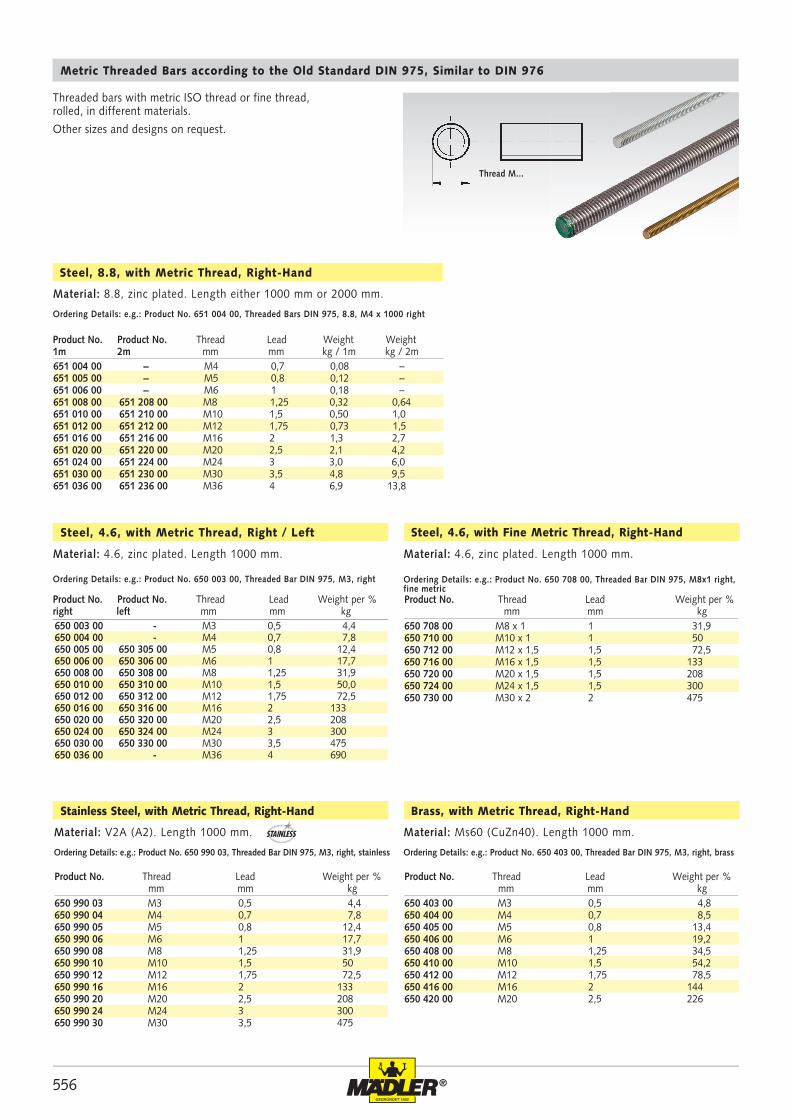
Thread M...
Metric Threaded Bars according to the Old Standard DIN 975, Similar to DIN 976
Ordering Details: e.g.: Product No. 650 003 00, Threaded Bar DIN 975, M3, right
Steel, 4.6, with Metric Thread, Right / Left
Material: 4.6, zinc plated. Length 1000 mm.
Product No. Product No. Thread Lead Weight per %right left mm mm kg
Ordering Details: e.g.: Product No. 650 708 00, Threaded Bar DIN 975, M8x1 right, fine metric
Steel, 4.6, with Fine Metric Thread, Right-Hand
Material: 4.6, zinc plated. Length 1000 mm.
Product No. Thread Lead Weight per % mm mm kg
Ordering Details: e.g.: Product No. 650 990 03, Threaded Bar DIN 975, M3, right, stainless
Stainless Steel, with Metric Thread, Right-Hand
Material: V2A (A2). Length 1000 mm.
Product No. Thread Lead Weight per % mm mm kg
Ordering Details: e.g.: Product No. 650 403 00, Threaded Bar DIN 975, M3, right, brass
Brass, with Metric Thread, Right-Hand
Material: Ms60 (CuZn40). Length 1000 mm.
Product No. Thread Lead Weight per % mm mm kg
Threaded bars with metric ISO thread or fine thread, rolled, in different materials.
Other sizes and designs on request.
Ordering Details: e.g.: Product No. 651 004 00, Threaded Bars DIN 975, 8.8, M4 x 1000 right
Steel, 8.8, with Metric Thread, Right-Hand
Material: 8.8, zinc plated. Length either 1000 mm or 2000 mm.
Product No. Product No. Thread Lead Weight Weight1m 2m mm mm kg / 1m kg / 2m
STAINLESS
557®
652 305 00 M5 8 0,12652 306 00 M6 10 0,25652 308 00 M8 13 0,52652 310 00 M10 17 1,16652 312 00 M12 19 1,73652 316 00 M16 24 3,33652 320 00 M20 30 6,40652 324 00 M24 36 11,00652 330 00 M30 46 22,30
652 508 00 M8 x 1 13 0,52652 510 00 M10 x 1 17 1,16652 512 00 M12 x 1,5 19 1,73652 516 00 M16 x 1,5 24 3,33652 520 00 M20 x 1,5 30 6,40652 524 00 M24 x 1,5 36 11,00652 530 00 M30 x 2 46 22,30
653 358 00 M8 17 14 13 12653 360 00 M10 21 17,5 16 27653 362 00 M12 24 21,5 18 38653 366 00 M16 30 28 24 68653 370 00 M20 36 35 30 140653 374 00 M24 44 42,5 36 255653 380 00 M30 55 56 46 530
sw
652 003 00 652 990 03 - 652 703 00 M3 0,5 5,5 2,4 0,04 0,04652 004 00 652 990 04 - 652 704 00 M4 0,7 7 3,2 0,08 0,09652 005 00 652 990 05 - 652 705 00 M5 0,8 8 4 0,12 0,13652 006 00 652 990 06 - 652 706 00 M6 1,0 10 5 0,25 0,27652 008 00 652 990 08 652 991 08 652 708 00 M8 1,25 13 6,5 0,52 0,56652 010 00 652 990 10 652 991 10 652 710 00 M10 1,5 17 8 1,16 1,24652 012 00 652 990 12 652 991 12 652 712 00 M12 1,75 19 10 1,73 1,85652 016 00 652 990 16 652 991 16 652 716 00 M16 2,0 24 13 3,33 3,56652 020 00 652 990 20 652 991 20 652 720 00 M20 2,5 30 16 6,40 6,85652 024 00 652 990 24 652 991 24 652 724 00 M24 3,0 36 19 11,0 11,8652 030 00 652 990 30 652 991 30 652 730 00 M30 3,5 46 24 22,3 23,9652 036 00 652 990 36 652 991 36 - M36 4,0 55 29 39,3 -
Hexagon Nuts DIN 934
Ordering Details: e.g.: Product No. 652 003 00, Hexagon Nut DIN 934, M3, Right
Hexagon Nuts with metric thread, right hand
Hexagon Nuts with metric thread, left hand
Ordering Details: e.g.: Product No. 652 305 00, Hexagon Nut DIN 934, M5, Left Ordering Details: e.g.: Product No. 652 508 00, Hexagon Nut DIN 934, M8 fine
Product No. Thread Width Across Flats Weight mm mm kg p.% Pcs.
Product No. Thread Width Across Flats Weight mm mm kg p.% Pcs.
Material: Steel, tensile strength 8, zinc-plated.Stainless steel V2A(A2).Stainless steel V4A(A4).Brass CuZn40 (Ms60).
Material: Steel, tensile strength 8, zinc-plated. Material: Steel, tensile strength 8, zinc-plated.
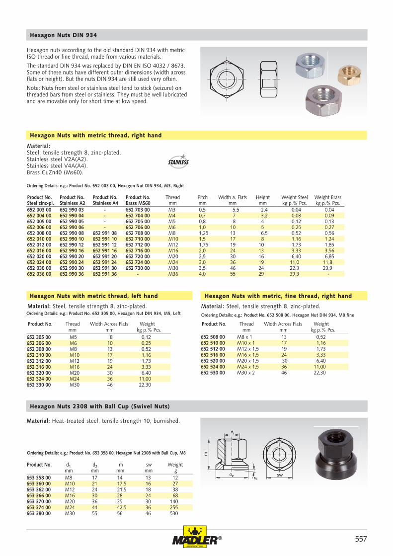
Material: Heat-treated steel, tensile strength 10, burnished.
Hexagon Nuts 2308 with Ball Cup (Swivel Nuts)
Ordering Details: e.g.: Product No. 653 358 00, Hexagon Nut 2308 with Ball Cup, M8
Product No. d1 d2 m sw Weight mm mm mm mm g
Hexagon Nuts with metric, fine thread, right hand
Hexagon nuts according to the old standard DIN 934 with metric ISO thread or fine thread, made from various materials.
The standard DIN 934 was replaced by DIN EN ISO 4032 / 8673. Some of these nuts have different outer dimensions (width across flats or height). But the nuts DIN 934 are still used very often.
Note: Nuts from steel or stainless steel tend to stick (seizure) on threaded bars from steel or stainless. They must be well lubricated and are movable only for short time at low speed.
STAINLESS
Product No. Product No. Product No. Product No. Thread Pitch Width a. Flats Height Weight Steel Weight BrassSteel zinc-pl. Stainless A2 Stainless A4 Brass MS60 mm mm mm mm kg p.% Pcs. kg p.% Pcs.
558 ®
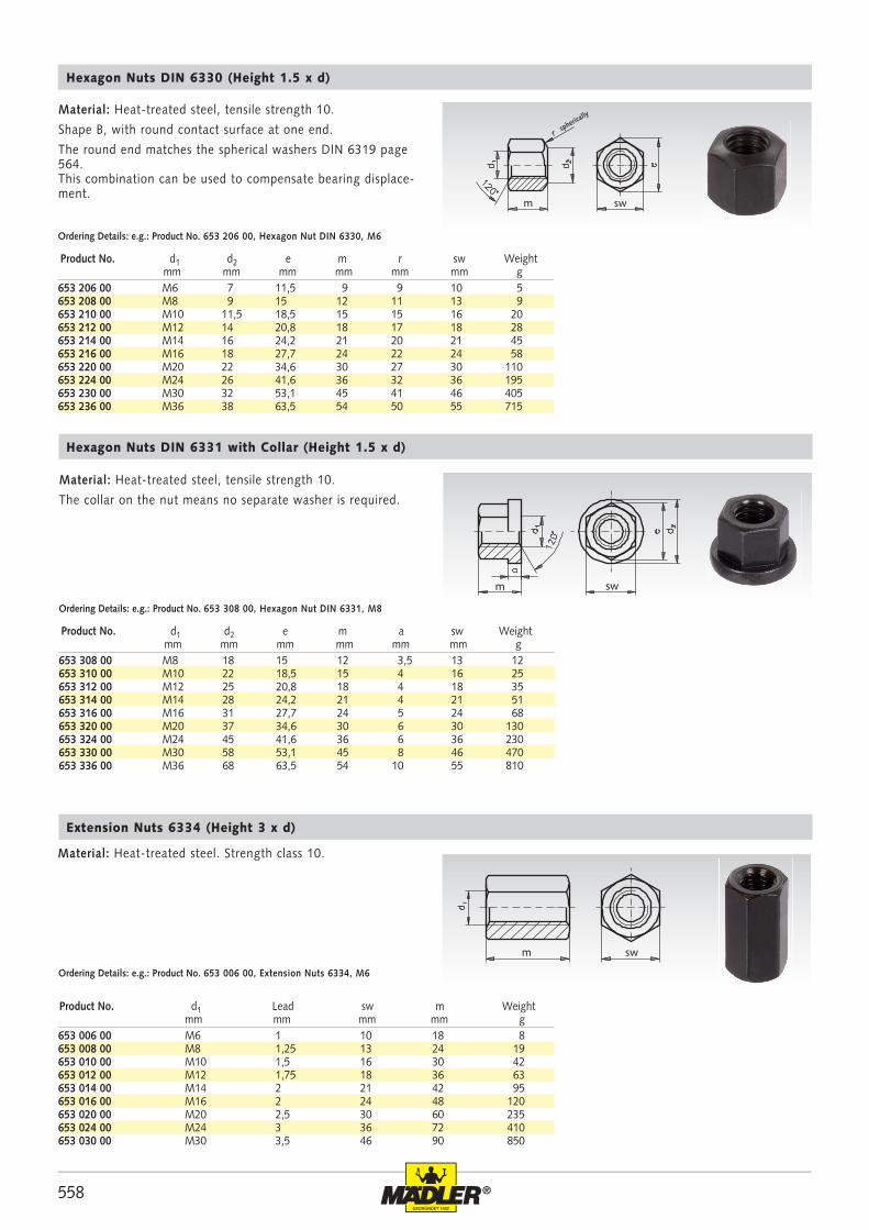
653 206 00 M6 7 11,5 9 9 10 5653 208 00 M8 9 15 12 11 13 9653 210 00 M10 11,5 18,5 15 15 16 20653 212 00 M12 14 20,8 18 17 18 28653 214 00 M14 16 24,2 21 20 21 45653 216 00 M16 18 27,7 24 22 24 58653 220 00 M20 22 34,6 30 27 30 110653 224 00 M24 26 41,6 36 32 36 195653 230 00 M30 32 53,1 45 41 46 405653 236 00 M36 38 63,5 54 50 55 715
653 308 00 M8 18 15 12 3,5 13 12653 310 00 M10 22 18,5 15 4 16 25653 312 00 M12 25 20,8 18 4 18 35653 314 00 M14 28 24,2 21 4 21 51653 316 00 M16 31 27,7 24 5 24 68653 320 00 M20 37 34,6 30 6 30 130653 324 00 M24 45 41,6 36 6 36 230653 330 00 M30 58 53,1 45 8 46 470653 336 00 M36 68 63,5 54 10 55 810
653 006 00 M6 1 10 18 8653 008 00 M8 1,25 13 24 19653 010 00 M10 1,5 16 30 42653 012 00 M12 1,75 18 36 63653 014 00 M14 2 21 42 95653 016 00 M16 2 24 48 120653 020 00 M20 2,5 30 60 235653 024 00 M24 3 36 72 410653 030 00 M30 3,5 46 90 850
swm
m sw
m sw
Material: Heat-treated steel, tensile strength 10.
Shape B, with round contact surface at one end.
The round end matches the spherical washers DIN 6319 page 564. This combination can be used to compensate bearing displace-ment.
Hexagon Nuts DIN 6330 (Height 1.5 x d)
Ordering Details: e.g.: Product No. 653 206 00, Hexagon Nut DIN 6330, M6
Material: Heat-treated steel, tensile strength 10.
The collar on the nut means no separate washer is required.
Hexagon Nuts DIN 6331 with Collar (Height 1.5 x d)
Ordering Details: e.g.: Product No. 653 308 00, Hexagon Nut DIN 6331, M8
Material: Heat-treated steel. Strength class 10.
Extension Nuts 6334 (Height 3 x d)
Ordering Details: e.g.: Product No. 653 006 00, Extension Nuts 6334, M6
Product No. d1 d2 e m r sw Weight mm mm mm mm mm mm g
Product No. d1 d2 e m a sw Weight mm mm mm mm mm mm g
Product No. d1 Lead sw m Weight mm mm mm mm g
spherically
559®
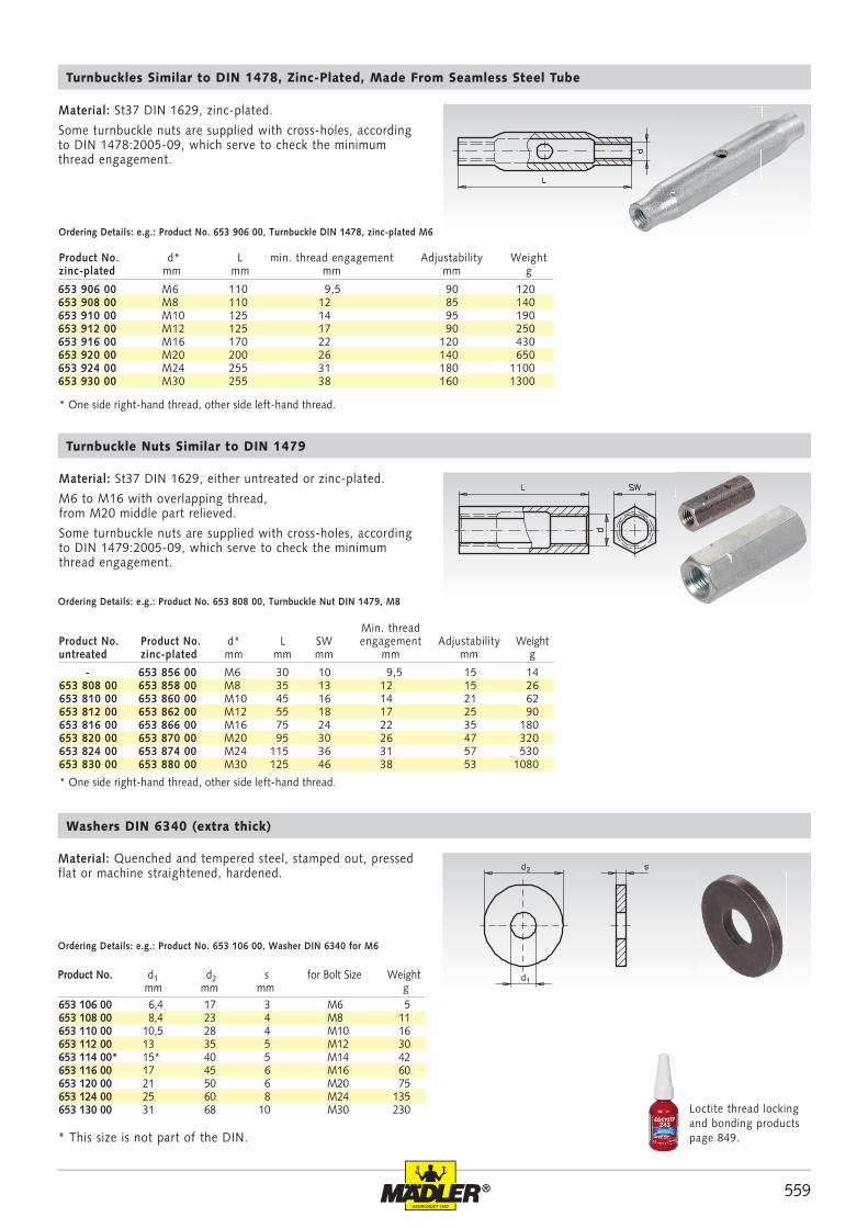
- 653 856 00 M6 30 10 9,5 15 14653 808 00 653 858 00 M8 35 13 12 15 26653 810 00 653 860 00 M10 45 16 14 21 62653 812 00 653 862 00 M12 55 18 17 25 90653 816 00 653 866 00 M16 75 24 22 35 180653 820 00 653 870 00 M20 95 30 26 47 320653 824 00 653 874 00 M24 115 36 31 57 530653 830 00 653 880 00 M30 125 46 38 53 1080
653 906 00 M6 110 9,5 90 120653 908 00 M8 110 12 85 140653 910 00 M10 125 14 95 190653 912 00 M12 125 17 90 250653 916 00 M16 170 22 120 430653 920 00 M20 200 26 140 650653 924 00 M24 255 31 180 1100653 930 00 M30 255 38 160 1300
653 106 00 6,4 17 3 M6 5653 108 00 8,4 23 4 M8 11653 110 00 10,5 28 4 M10 16653 112 00 13 35 5 M12 30653 114 00* 15* 40 5 M14 42653 116 00 17 45 6 M16 60653 120 00 21 50 6 M20 75653 124 00 25 60 8 M24 135653 130 00 31 68 10 M30 230
Min. thread Product No. Product No. d* L SW engagement Adjustability Weightuntreated zinc-plated mm mm mm mm mm g
Product No. d* L min. thread engagement Adjustability Weightzinc-plated mm mm mm mm g
Turnbuckles Similar to DIN 1478, Zinc-Plated, Made From Seamless Steel Tube
Material: St37 DIN 1629, zinc-plated.
Some turnbuckle nuts are supplied with cross-holes, according to DIN 1478:2005-09, which serve to check the minimum thread engagement.
Ordering Details: e.g.: Product No. 653 906 00, Turnbuckle DIN 1478, zinc-plated M6
Turnbuckle Nuts Similar to DIN 1479
Material: St37 DIN 1629, either untreated or zinc-plated.
M6 to M16 with overlapping thread, from M20 middle part relieved.
Some turnbuckle nuts are supplied with cross-holes, according to DIN 1479:2005-09, which serve to check the minimum thread engagement.
Ordering Details: e.g.: Product No. 653 808 00, Turnbuckle Nut DIN 1479, M8
* One side right-hand thread, other side left-hand thread.
* One side right-hand thread, other side left-hand thread.
Loctite thread locking and bonding products page 849.
Ordering Details: e.g.: Product No. 653 106 00, Washer DIN 6340 for M6
Product No. d1 d2 s for Bolt Size Weight mm mm mm g
* This size is not part of the DIN.
Material: Quenched and tempered steel, stamped out, pressed flat or machine straightened, hardened.
Washers DIN 6340 (extra thick)
560 ®
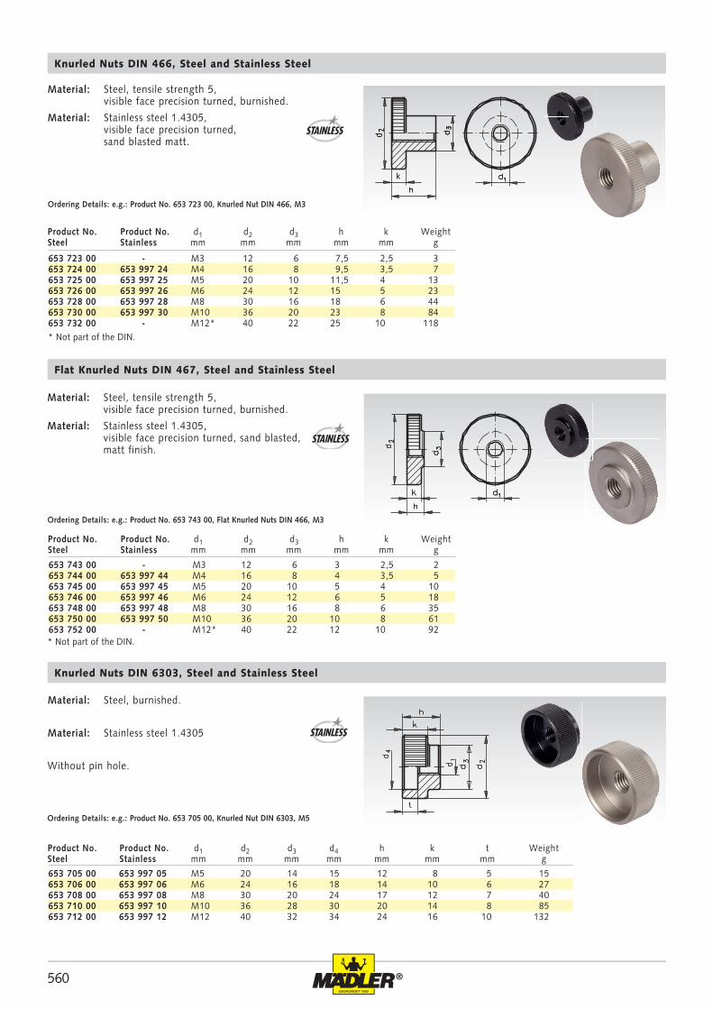
653 723 00 - M3 12 6 7,5 2,5 3653 724 00 653 997 24 M4 16 8 9,5 3,5 7653 725 00 653 997 25 M5 20 10 11,5 4 13653 726 00 653 997 26 M6 24 12 15 5 23653 728 00 653 997 28 M8 30 16 18 6 44653 730 00 653 997 30 M10 36 20 23 8 84653 732 00 - M12* 40 22 25 10 118
653 743 00 - M3 12 6 3 2,5 2653 744 00 653 997 44 M4 16 8 4 3,5 5653 745 00 653 997 45 M5 20 10 5 4 10653 746 00 653 997 46 M6 24 12 6 5 18653 748 00 653 997 48 M8 30 16 8 6 35653 750 00 653 997 50 M10 36 20 10 8 61653 752 00 - M12* 40 22 12 10 92
653 705 00 653 997 05 M5 20 14 15 12 8 5 15653 706 00 653 997 06 M6 24 16 18 14 10 6 27653 708 00 653 997 08 M8 30 20 24 17 12 7 40653 710 00 653 997 10 M10 36 28 30 20 14 8 85653 712 00 653 997 12 M12 40 32 34 24 16 10 132
Knurled Nuts DIN 466, Steel and Stainless Steel
Product No. Product No. d1 d2 d3 h k WeightSteel Stainless mm mm mm mm mm g
Material: Steel, tensile strength 5, visible face precision turned, burnished.
Material: Stainless steel 1.4305, visible face precision turned, sand blasted matt.
Ordering Details: e.g.: Product No. 653 723 00, Knurled Nut DIN 466, M3
* Not part of the DIN.
Flat Knurled Nuts DIN 467, Steel and Stainless Steel
Product No. Product No. d1 d2 d3 h k WeightSteel Stainless mm mm mm mm mm g
Material: Steel, tensile strength 5, visible face precision turned, burnished.
Material: Stainless steel 1.4305, visible face precision turned, sand blasted, matt finish.
Ordering Details: e.g.: Product No. 653 743 00, Flat Knurled Nuts DIN 466, M3
Knurled Nuts DIN 6303, Steel and Stainless Steel
Material: Steel, burnished.
Material: Stainless steel 1.4305
Without pin hole.
Ordering Details: e.g.: Product No. 653 705 00, Knurled Nut DIN 6303, M5
* Not part of the DIN.
Product No. Product No. d1 d2 d3 d4 h k t WeightSteel Stainless mm mm mm mm mm mm mm g
STAINLESS
STAINLESS
STAINLESS
561®
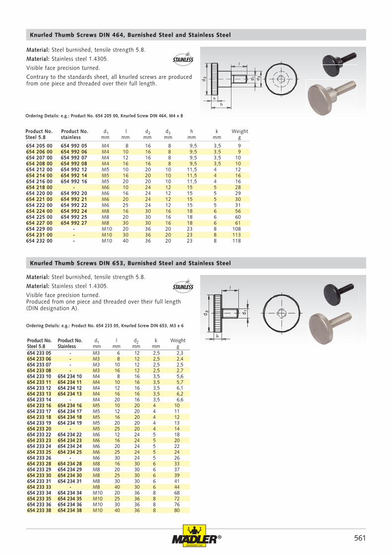
654 205 00 654 992 05 M4 8 16 8 9,5 3,5 9654 206 00 654 992 06 M4 10 16 8 9,5 3,5 9654 207 00 654 992 07 M4 12 16 8 9,5 3,5 10654 208 00 654 992 08 M4 16 16 8 9,5 3,5 10654 212 00 654 992 12 M5 10 20 10 11,5 4 12654 214 00 654 992 14 M5 16 20 10 11,5 4 16654 216 00 654 992 16 M5 20 20 10 11,5 4 16654 218 00 - M6 10 24 12 15 5 28654 220 00 654 992 20 M6 16 24 12 15 5 29654 221 00 654 992 21 M6 20 24 12 15 5 30654 222 00 654 992 22 M6 25 24 12 15 5 31654 224 00 654 992 24 M8 16 30 16 18 6 56654 225 00 654 992 25 M8 20 30 16 18 6 60654 227 00 654 992 27 M8 30 30 16 18 6 61654 229 00 - M10 20 36 20 23 8 108654 231 00 - M10 30 36 20 23 8 113654 232 00 - M10 40 36 20 23 8 118
654 233 05 - M3 6 12 2,5 2,3654 233 06 - M3 8 12 2,5 2,4654 233 07 - M3 10 12 2,5 2,5654 233 08 - M3 16 12 2,5 2,7654 233 10 654 234 10 M4 8 16 3,5 5,6654 233 11 654 234 11 M4 10 16 3,5 5,7654 233 12 654 234 12 M4 12 16 3,5 6,1654 233 13 654 234 13 M4 16 16 3,5 6,2654 233 14 - M4 20 16 3,5 6,6654 233 16 654 234 16 M5 10 20 4 10654 233 17 654 234 17 M5 12 20 4 11654 233 18 654 234 18 M5 16 20 4 12654 233 19 654 234 19 M5 20 20 4 13654 233 20 - M5 25 20 4 14654 233 22 654 234 22 M6 12 24 5 18654 233 23 654 234 23 M6 16 24 5 20654 233 24 654 234 24 M6 20 24 5 22654 233 25 654 234 25 M6 25 24 5 24654 233 26 - M6 30 24 5 26654 233 28 654 234 28 M8 16 30 6 33654 233 29 654 234 29 M8 20 30 6 37654 233 30 654 234 30 M8 25 30 6 39654 233 31 654 234 31 M8 30 30 6 41654 233 33 - M8 40 30 6 44654 233 34 654 234 34 M10 20 36 8 68654 233 35 654 234 35 M10 25 36 8 72654 233 36 654 234 36 M10 30 36 8 76654 233 38 654 234 38 M10 40 36 8 80
Knurled Thumb Screws DIN 464, Burnished Steel and Stainless Steel
Product No. Product No. d1 l d2 d3 h k WeightSteel 5.8 stainless mm mm mm mm mm mm g
Material: Steel burnished, tensile strength 5.8.
Material: Stainless steel 1.4305.
Visible face precision turned.
Contrary to the standards sheet, all knurled screws are produced from one piece and threaded over their full length.
Ordering Details: e.g.: Product No. 654 205 00, Knurled Screw DIN 464, M4 x 8
STAINLESS
Material: Steel burnished, tensile strength 5.8.
Material: Stainless steel 1.4305.
Visible face precision turned.Produced from one piece and threaded over their full length (DIN designation A).
Knurled Thumb Screws DIN 653, Burnished Steel and Stainless Steel
Product No. Product No. d1 l d2 k WeightSteel 5.8 Stainless mm mm mm mm g
Ordering Details: e.g.: Product No. 654 233 05, Knurled Screw DIN 653, M3 x 6
STAINLESS
562 ®
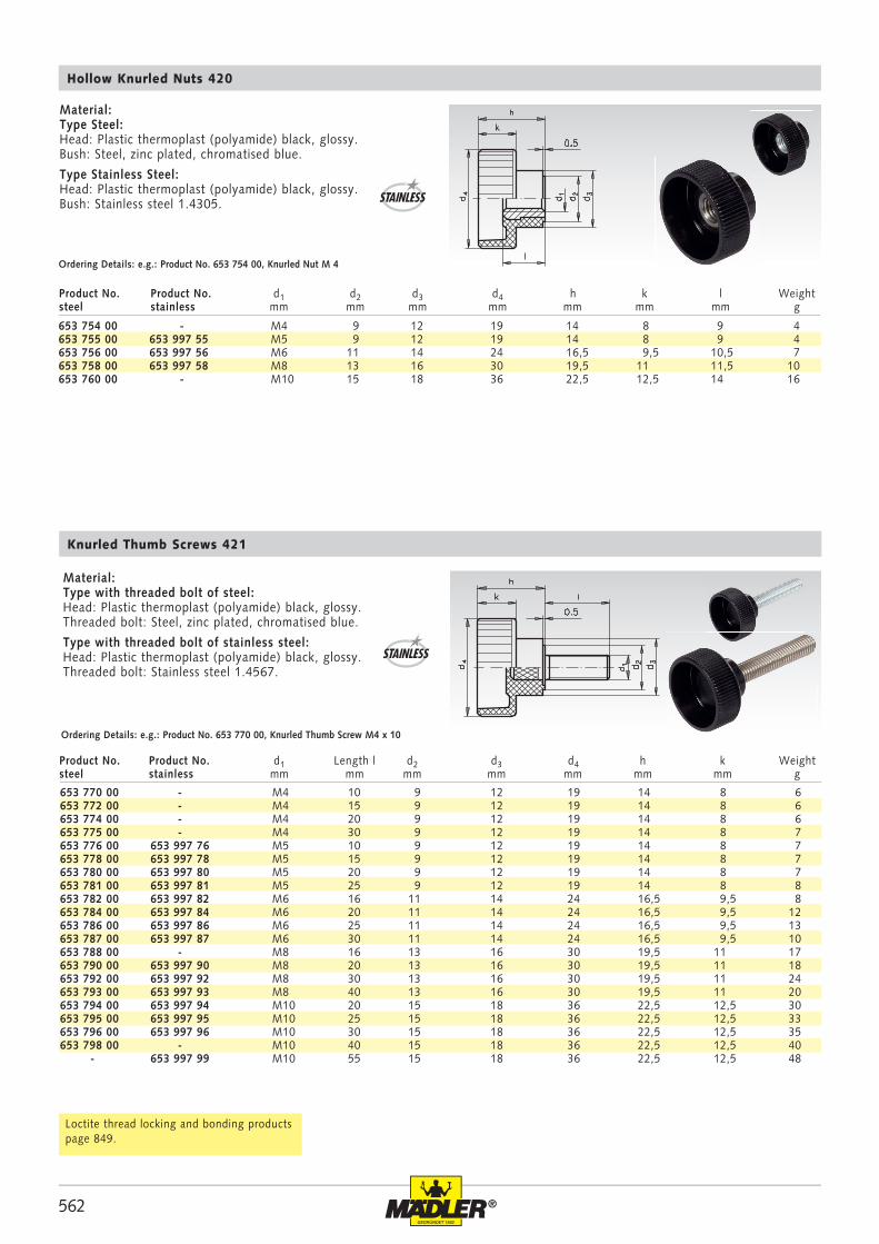
653 754 00 - M4 9 12 19 14 8 9 4653 755 00 653 997 55 M5 9 12 19 14 8 9 4653 756 00 653 997 56 M6 11 14 24 16,5 9,5 10,5 7653 758 00 653 997 58 M8 13 16 30 19,5 11 11,5 10653 760 00 - M10 15 18 36 22,5 12,5 14 16
653 770 00 - M4 10 9 12 19 14 8 6653 772 00 - M4 15 9 12 19 14 8 6653 774 00 - M4 20 9 12 19 14 8 6653 775 00 - M4 30 9 12 19 14 8 7653 776 00 653 997 76 M5 10 9 12 19 14 8 7653 778 00 653 997 78 M5 15 9 12 19 14 8 7653 780 00 653 997 80 M5 20 9 12 19 14 8 7653 781 00 653 997 81 M5 25 9 12 19 14 8 8653 782 00 653 997 82 M6 16 11 14 24 16,5 9,5 8653 784 00 653 997 84 M6 20 11 14 24 16,5 9,5 12653 786 00 653 997 86 M6 25 11 14 24 16,5 9,5 13653 787 00 653 997 87 M6 30 11 14 24 16,5 9,5 10653 788 00 - M8 16 13 16 30 19,5 11 17653 790 00 653 997 90 M8 20 13 16 30 19,5 11 18653 792 00 653 997 92 M8 30 13 16 30 19,5 11 24653 793 00 653 997 93 M8 40 13 16 30 19,5 11 20653 794 00 653 997 94 M10 20 15 18 36 22,5 12,5 30653 795 00 653 997 95 M10 25 15 18 36 22,5 12,5 33653 796 00 653 997 96 M10 30 15 18 36 22,5 12,5 35653 798 00 - M10 40 15 18 36 22,5 12,5 40 - 653 997 99 M10 55 15 18 36 22,5 12,5 48
Hollow Knurled Nuts 420
Material: Type Steel: Head: Plastic thermoplast (polyamide) black, glossy. Bush: Steel, zinc plated, chromatised blue.
Type Stainless Steel: Head: Plastic thermoplast (polyamide) black, glossy. Bush: Stainless steel 1.4305.
Ordering Details: e.g.: Product No. 653 754 00, Knurled Nut M 4
Knurled Thumb Screws 421
Material: Type with threaded bolt of steel: Head: Plastic thermoplast (polyamide) black, glossy.Threaded bolt: Steel, zinc plated, chromatised blue.
Type with threaded bolt of stainless steel: Head: Plastic thermoplast (polyamide) black, glossy.Threaded bolt: Stainless steel 1.4567.
Ordering Details: e.g.: Product No. 653 770 00, Knurled Thumb Screw M4 x 10
Loctite thread locking and bonding products page 849.
Product No. Product No. d1 Length l d2 d3 d4 h k Weightsteel stainless mm mm mm mm mm mm mm g
Product No. Product No. d1 d2 d3 d4 h k l Weightsteel stainless mm mm mm mm mm mm mm g
STAINLESS
STAINLESS
563®
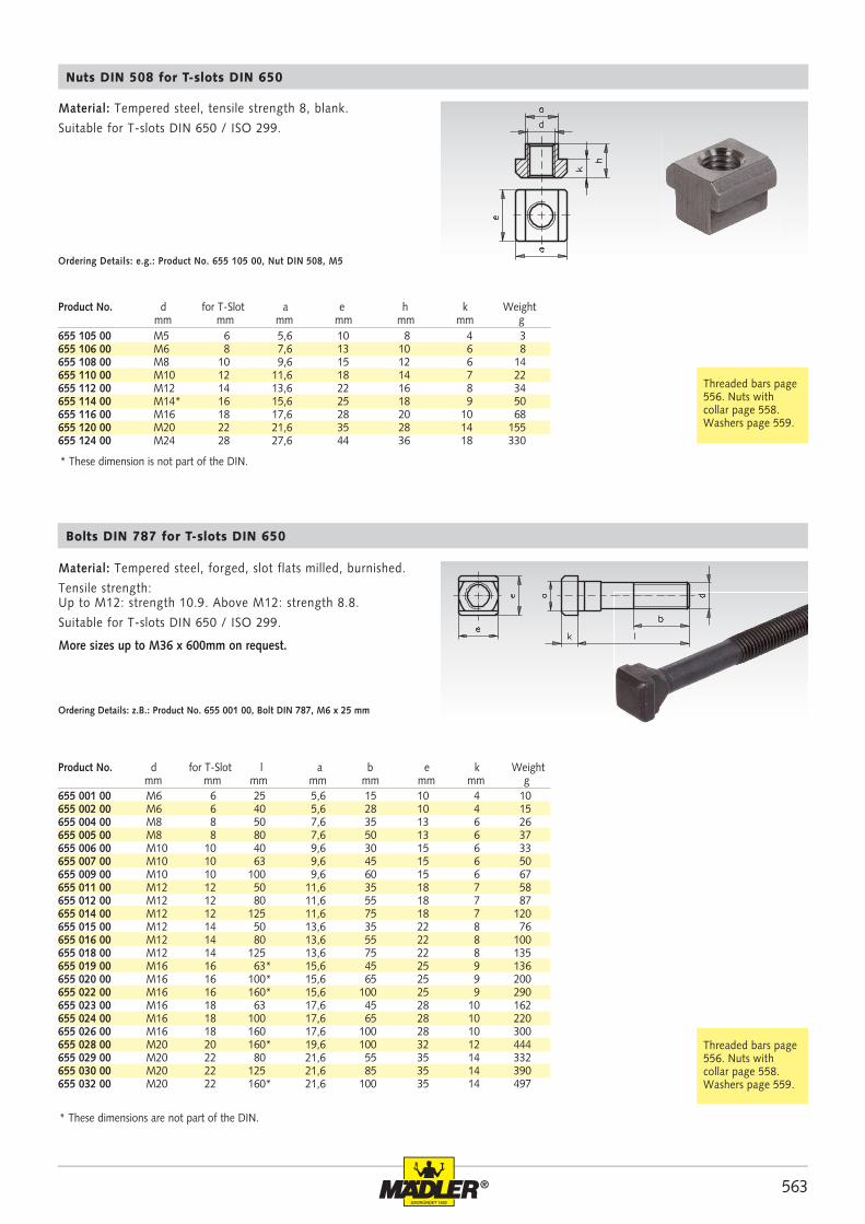
655 105 00 M5 6 5,6 10 8 4 3655 106 00 M6 8 7,6 13 10 6 8655 108 00 M8 10 9,6 15 12 6 14655 110 00 M10 12 11,6 18 14 7 22655 112 00 M12 14 13,6 22 16 8 34655 114 00 M14* 16 15,6 25 18 9 50655 116 00 M16 18 17,6 28 20 10 68655 120 00 M20 22 21,6 35 28 14 155655 124 00 M24 28 27,6 44 36 18 330
655 001 00 M6 6 25 5,6 15 10 4 10655 002 00 M6 6 40 5,6 28 10 4 15655 004 00 M8 8 50 7,6 35 13 6 26655 005 00 M8 8 80 7,6 50 13 6 37655 006 00 M10 10 40 9,6 30 15 6 33655 007 00 M10 10 63 9,6 45 15 6 50655 009 00 M10 10 100 9,6 60 15 6 67655 011 00 M12 12 50 11,6 35 18 7 58655 012 00 M12 12 80 11,6 55 18 7 87655 014 00 M12 12 125 11,6 75 18 7 120655 015 00 M12 14 50 13,6 35 22 8 76655 016 00 M12 14 80 13,6 55 22 8 100655 018 00 M12 14 125 13,6 75 22 8 135655 019 00 M16 16 63* 15,6 45 25 9 136655 020 00 M16 16 100* 15,6 65 25 9 200655 022 00 M16 16 160* 15,6 100 25 9 290655 023 00 M16 18 63 17,6 45 28 10 162655 024 00 M16 18 100 17,6 65 28 10 220655 026 00 M16 18 160 17,6 100 28 10 300655 028 00 M20 20 160* 19,6 100 32 12 444655 029 00 M20 22 80 21,6 55 35 14 332655 030 00 M20 22 125 21,6 85 35 14 390655 032 00 M20 22 160* 21,6 100 35 14 497
Material: Tempered steel, tensile strength 8, blank.
Suitable for T-slots DIN 650 / ISO 299.
Nuts DIN 508 for T-slots DIN 650
Ordering Details: e.g.: Product No. 655 105 00, Nut DIN 508, M5
Product No. d for T-Slot a e h k Weight mm mm mm mm mm mm g
Material: Tempered steel, forged, slot flats milled, burnished.
Tensile strength:Up to M12: strength 10.9. Above M12: strength 8.8.
Suitable for T-slots DIN 650 / ISO 299.
More sizes up to M36 x 600mm on request.
Bolts DIN 787 for T-slots DIN 650
Ordering Details: z.B.: Product No. 655 001 00, Bolt DIN 787, M6 x 25 mm
Product No. d for T-Slot l a b e k Weight mm mm mm mm mm mm mm g
* These dimensions are not part of the DIN.
Threaded bars page 556. Nuts with collar page 558. Washers page 559.
Threaded bars page 556. Nuts with collar page 558. Washers page 559.
* These dimension is not part of the DIN.
564 ®
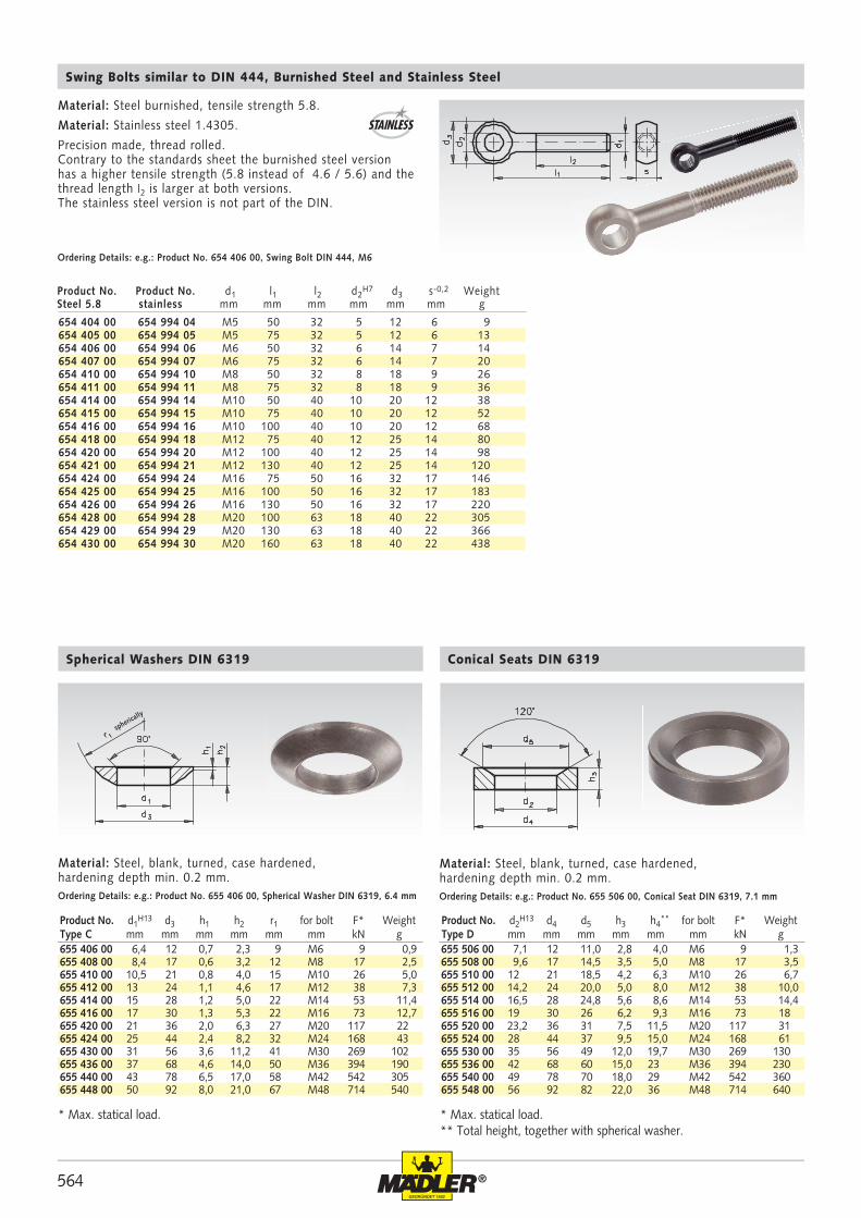
654 404 00 654 994 04 M5 50 32 5 12 6 9654 405 00 654 994 05 M5 75 32 5 12 6 13654 406 00 654 994 06 M6 50 32 6 14 7 14654 407 00 654 994 07 M6 75 32 6 14 7 20654 410 00 654 994 10 M8 50 32 8 18 9 26654 411 00 654 994 11 M8 75 32 8 18 9 36654 414 00 654 994 14 M10 50 40 10 20 12 38654 415 00 654 994 15 M10 75 40 10 20 12 52654 416 00 654 994 16 M10 100 40 10 20 12 68654 418 00 654 994 18 M12 75 40 12 25 14 80654 420 00 654 994 20 M12 100 40 12 25 14 98654 421 00 654 994 21 M12 130 40 12 25 14 120654 424 00 654 994 24 M16 75 50 16 32 17 146654 425 00 654 994 25 M16 100 50 16 32 17 183654 426 00 654 994 26 M16 130 50 16 32 17 220654 428 00 654 994 28 M20 100 63 18 40 22 305654 429 00 654 994 29 M20 130 63 18 40 22 366654 430 00 654 994 30 M20 160 63 18 40 22 438
655 406 00 6,4 12 0,7 2,3 9 M6 9 0,9655 408 00 8,4 17 0,6 3,2 12 M8 17 2,5655 410 00 10,5 21 0,8 4,0 15 M10 26 5,0655 412 00 13 24 1,1 4,6 17 M12 38 7,3655 414 00 15 28 1,2 5,0 22 M14 53 11,4655 416 00 17 30 1,3 5,3 22 M16 73 12,7655 420 00 21 36 2,0 6,3 27 M20 117 22655 424 00 25 44 2,4 8,2 32 M24 168 43655 430 00 31 56 3,6 11,2 41 M30 269 102655 436 00 37 68 4,6 14,0 50 M36 394 190655 440 00 43 78 6,5 17,0 58 M42 542 305655 448 00 50 92 8,0 21,0 67 M48 714 540
655 506 00 7,1 12 11,0 2,8 4,0 M6 9 1,3655 508 00 9,6 17 14,5 3,5 5,0 M8 17 3,5655 510 00 12 21 18,5 4,2 6,3 M10 26 6,7655 512 00 14,2 24 20,0 5,0 8,0 M12 38 10,0655 514 00 16,5 28 24,8 5,6 8,6 M14 53 14,4655 516 00 19 30 26 6,2 9,3 M16 73 18655 520 00 23,2 36 31 7,5 11,5 M20 117 31655 524 00 28 44 37 9,5 15,0 M24 168 61655 530 00 35 56 49 12,0 19,7 M30 269 130655 536 00 42 68 60 15,0 23 M36 394 230655 540 00 49 78 70 18,0 29 M42 542 360655 548 00 56 92 82 22,0 36 M48 714 640
Material: Steel, blank, turned, case hardened, hardening depth min. 0.2 mm.
Spherical Washers DIN 6319
Ordering Details: e.g.: Product No. 655 406 00, Spherical Washer DIN 6319, 6.4 mm
Material: Steel, blank, turned, case hardened, hardening depth min. 0.2 mm.Ordering Details: e.g.: Product No. 655 506 00, Conical Seat DIN 6319, 7.1 mm
Conical Seats DIN 6319
* Max. statical load.** Total height, together with spherical washer.
spherically
Product No. Product No. d1 l1 l2 d2H7 d3 s-0,2 Weight
Steel 5.8 stainless mm mm mm mm mm mm g
Swing Bolts similar to DIN 444, Burnished Steel and Stainless Steel
Material: Steel burnished, tensile strength 5.8.
Material: Stainless steel 1.4305.
Precision made, thread rolled. Contrary to the standards sheet the burnished steel version has a higher tensile strength (5.8 instead of 4.6 / 5.6) and the thread length l2 is larger at both versions. The stainless steel version is not part of the DIN.
Ordering Details: e.g.: Product No. 654 406 00, Swing Bolt DIN 444, M6
STAINLESS
Product No. d1H13 d3 h1 h2 r1 for bolt F* Weight
Type C mm mm mm mm mm mm kN gProduct No. d2
H13 d4 d5 h3 h4** for bolt F* Weight
Type D mm mm mm mm mm mm kN g
* Max. statical load.
565®
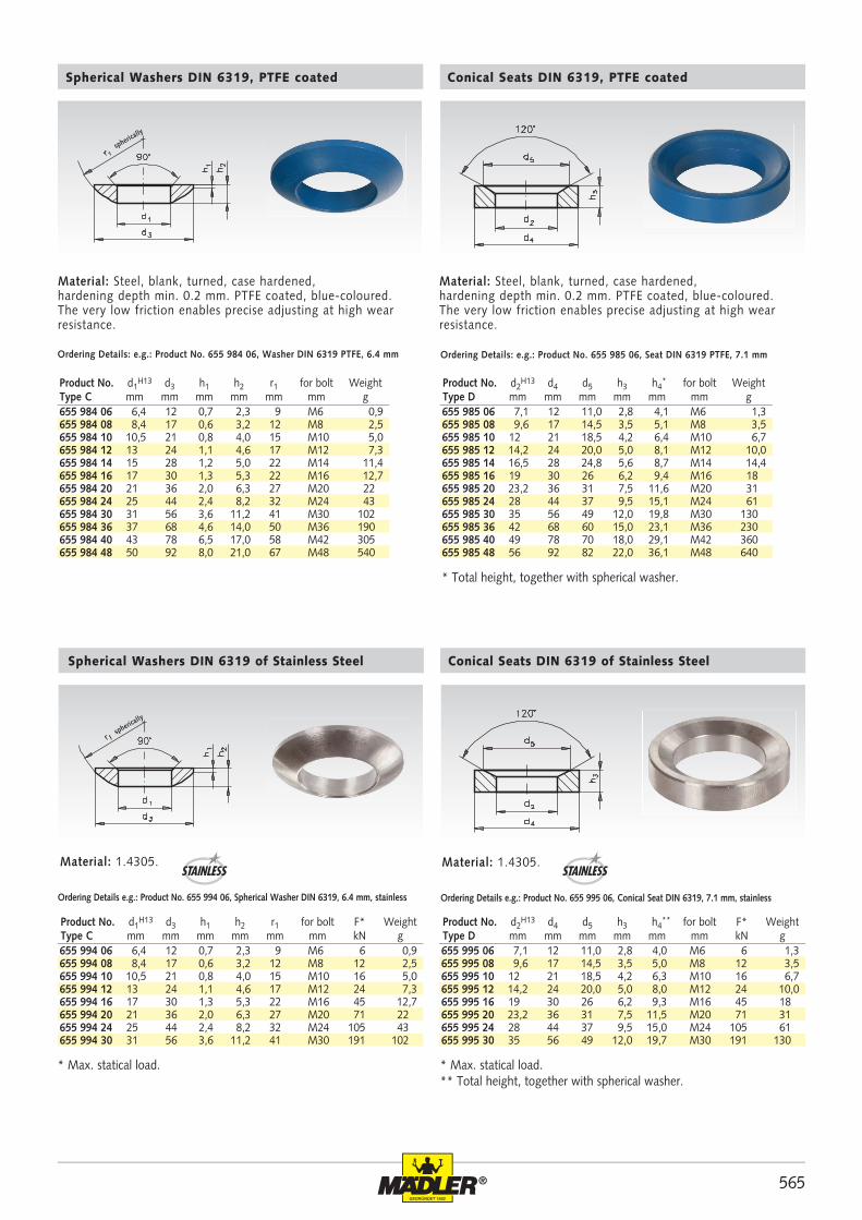
655 994 06 6,4 12 0,7 2,3 9 M6 6 0,9655 994 08 8,4 17 0,6 3,2 12 M8 12 2,5655 994 10 10,5 21 0,8 4,0 15 M10 16 5,0655 994 12 13 24 1,1 4,6 17 M12 24 7,3655 994 16 17 30 1,3 5,3 22 M16 45 12,7655 994 20 21 36 2,0 6,3 27 M20 71 22655 994 24 25 44 2,4 8,2 32 M24 105 43655 994 30 31 56 3,6 11,2 41 M30 191 102
655 995 06 7,1 12 11,0 2,8 4,0 M6 6 1,3655 995 08 9,6 17 14,5 3,5 5,0 M8 12 3,5655 995 10 12 21 18,5 4,2 6,3 M10 16 6,7655 995 12 14,2 24 20,0 5,0 8,0 M12 24 10,0655 995 16 19 30 26 6,2 9,3 M16 45 18655 995 20 23,2 36 31 7,5 11,5 M20 71 31655 995 24 28 44 37 9,5 15,0 M24 105 61655 995 30 35 56 49 12,0 19,7 M30 191 130
655 984 06 6,4 12 0,7 2,3 9 M6 0,9655 984 08 8,4 17 0,6 3,2 12 M8 2,5655 984 10 10,5 21 0,8 4,0 15 M10 5,0655 984 12 13 24 1,1 4,6 17 M12 7,3655 984 14 15 28 1,2 5,0 22 M14 11,4655 984 16 17 30 1,3 5,3 22 M16 12,7655 984 20 21 36 2,0 6,3 27 M20 22655 984 24 25 44 2,4 8,2 32 M24 43655 984 30 31 56 3,6 11,2 41 M30 102655 984 36 37 68 4,6 14,0 50 M36 190655 984 40 43 78 6,5 17,0 58 M42 305655 984 48 50 92 8,0 21,0 67 M48 540
655 985 06 7,1 12 11,0 2,8 4,1 M6 1,3655 985 08 9,6 17 14,5 3,5 5,1 M8 3,5655 985 10 12 21 18,5 4,2 6,4 M10 6,7655 985 12 14,2 24 20,0 5,0 8,1 M12 10,0655 985 14 16,5 28 24,8 5,6 8,7 M14 14,4655 985 16 19 30 26 6,2 9,4 M16 18655 985 20 23,2 36 31 7,5 11,6 M20 31655 985 24 28 44 37 9,5 15,1 M24 61655 985 30 35 56 49 12,0 19,8 M30 130655 985 36 42 68 60 15,0 23,1 M36 230655 985 40 49 78 70 18,0 29,1 M42 360655 985 48 56 92 82 22,0 36,1 M48 640
Spherical Washers DIN 6319 of Stainless Steel
Ordering Details e.g.: Product No. 655 994 06, Spherical Washer DIN 6319, 6.4 mm, stainless Ordering Details e.g.: Product No. 655 995 06, Conical Seat DIN 6319, 7.1 mm, stainless
Conical Seats DIN 6319 of Stainless Steel
Material: 1.4305. Material: 1.4305.
spherically
STAINLESS STAINLESS
Material: Steel, blank, turned, case hardened, hardening depth min. 0.2 mm. PTFE coated, blue-coloured. The very low friction enables precise adjusting at high wear resistance.
Material: Steel, blank, turned, case hardened, hardening depth min. 0.2 mm. PTFE coated, blue-coloured. The very low friction enables precise adjusting at high wear resistance.
Spherical Washers DIN 6319, PTFE coated
Ordering Details: e.g.: Product No. 655 984 06, Washer DIN 6319 PTFE, 6.4 mm Ordering Details: e.g.: Product No. 655 985 06, Seat DIN 6319 PTFE, 7.1 mm
Conical Seats DIN 6319, PTFE coated
spherically
Product No. d1H13 d3 h1 h2 r1 for bolt F* Weight
Type C mm mm mm mm mm mm kN gProduct No. d2
H13 d4 d5 h3 h4** for bolt F* Weight
Type D mm mm mm mm mm mm kN g
* Max. statical load.** Total height, together with spherical washer.* Max. statical load.
* Total height, together with spherical washer.
Product No. d1H13 d3 h1 h2 r1 for bolt Weight
Type C mm mm mm mm mm mm gProduct No. d2
H13 d4 d5 h3 h4* for bolt Weight
Type D mm mm mm mm mm mm g
566 ®
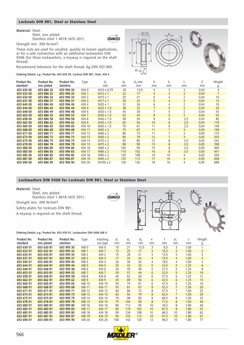
653 630 00 653 886 30 653 996 30 KM 0 M10 x 0,75 18 13,5 4 3 2 0,04 4653 632 00 653 886 32 653 996 32 KM 1 M12 x 1 22 17 4 3 2 0,04 7653 634 00 653 886 34 653 996 34 KM 2 M15 x 1 25 21 5 4 2 0,04 10653 637 00 653 886 37 653 996 37 KM 3 M17 x 1 28 24 5 4 2 0,04 13653 640 00 653 886 40 653 996 40 KM 4 M20 x 1 32 26 6 4 2 0,04 19653 644 00 653 886 44 653 996 44 KM 5 M25 x 1,5 38 32 7 5 2 0,04 25653 648 00 653 886 49 653 996 48 KM 6 M30 x 1,5 45 38 7 5 2 0,04 43653 653 00 653 886 53 653 996 53 KM 7 M35 x 1,5 52 44 8 5 2 0,04 53653 658 00 653 886 58 653 996 58 KM 8 M40 x 1,5 58 50 9 6 2,5 0,04 85653 662 00 653 886 62 653 996 62 KM 9 M45 x 1,5 65 56 10 6 2,5 0,04 119653 665 00 653 886 65 653 996 65 KM 10 M50 x 1,5 70 61 11 6 2,5 0,04 148653 668 00 653 886 68 653 996 68 KM 11 M55 x 2 75 67 11 7 3 0,05 158653 671 00 653 886 71 653 996 71 KM 12 M60 x 2 80 73 11 7 3 0,05 174653 673 00 653 886 73 653 996 73 KM 13 M65 x 2 85 79 12 7 3 0,05 203653 675 00 653 886 75 653 996 75 KM 14 M70 x 2 92 85 12 8 3,5 0,05 242653 678 00 653 886 78 653 996 78 KM 15 M75 x 2 98 90 13 8 3,5 0,05 298653 680 00 653 886 80 653 996 80 KM 16 M80 x 2 105 95 15 8 3,5 0,05 400653 683 00 653 886 83 653 996 83 KM 17 M85 x 2 110 102 16 8 3,5 0,05 451653 685 00 653 886 85 653 996 85 KM 18 M90 x 2 120 108 16 10 4 0,05 556653 687 00 653 886 87 653 996 87 KM 19 M95 x 2 125 113 17 10 4 0,05 658653 690 00 653 886 90 653 996 90 KM 20 M100 x 2 130 120 18 10 4 0,05 698
653 630 01 653 630 81 653 995 30 MB 0 KM 0 10 21 13,5 3 8,5 3 1,00 1653 632 01 653 632 81 653 995 32 MB 1 KM 1 12 25 17 3 10,5 3 1,00 2653 634 01 653 634 81 653 995 34 MB 2 KM 2 15 28 21 4 13,5 4 1,00 3653 637 01 653 637 81 653 995 37 MB 3 KM 3 17 32 24 4 15,5 4 1,00 3653 640 01 653 640 81 653 995 40 MB 4 KM 4 20 36 26 4 18,5 4 1,00 4653 644 01 653 644 81 653 995 44 MB 5 KM 5 25 42 32 5 23,0 5 1,25 6653 648 01 653 648 81 653 995 48 MB 6 KM 6 30 49 38 5 27,5 5 1,25 8653 653 01 653 653 81 653 995 53 MB 7 KM 7 35 57 44 6 32,5 5 1,25 10653 658 01 653 658 81 653 995 58 MB 8 KM 8 40 62 50 6 37,5 6 1,25 12653 662 01 653 662 81 653 995 62 MB 9 KM 9 45 69 56 6 42,5 6 1,25 15653 665 01 653 665 81 653 995 65 MB 10 KM 10 50 74 61 6 47,5 6 1,25 16653 668 01 653 668 81 653 995 68 MB 11 KM 11 55 81 67 8 52,5 7 1,50 20653 671 01 653 671 81 653 995 71 MB 12 KM 12 60 86 73 8 57,5 7 1,50 25653 673 01 653 673 81 653 995 73 MB 13 KM 13 65 92 79 8 62,5 7 1,50 29653 675 01 653 675 81 653 995 75 MB 14 KM 14 70 98 85 8 66,5 8 1,50 33653 678 01 653 678 81 653 995 78 MB 15 KM 15 75 104 90 8 71,5 8 1,50 36653 680 01 653 680 81 653 995 80 MB 16 KM 16 80 112 95 10 76,5 8 1,80 46653 683 01 653 683 81 653 995 83 MB 17 KM 17 85 119 102 10 81,5 8 1,80 52653 685 01 653 685 81 653 995 85 MB 18 KM 18 90 126 108 10 86,5 10 1,80 62653 687 01 653 687 81 653 995 87 MB 19 KM 19 95 133 113 10 91,5 10 1,80 67653 690 01 653 690 81 653 995 90 MB 20 KM 20 100 142 120 12 96,5 10 1,80 77
d1s
e
~25°
fd 2
b1
Z
h30°
d 1d 2 d 3
b
t
Ordering Details: e.g.: Product No. 653 630 00, Locknut DIN 981, Steel, KM 0
STAINLESS
Material: Steel. Steel, zinc plated. Stainless steel 1.4618 (AISI 201).Strength min. 350 N/mm2.These nuts are used for unsafed, quickly to loosen applications, or for a safe connection with an additional lockwasher DIN 5406 (for these lockwashers, a keyway is required on the shaft thread). Recommend tolerance for the shaft thread: 6g DIN ISO 965.
Locknuts DIN 981, Steel or Stainless Steel
Product No. Product No. Product No. Type d1 d2 d3 min. h b t Z Weightstandard zinc plated stainless mm mm mm mm mm mm mm g
Product No. Product No. Product No. Type matching d1 d2 d3 e f b1 s Weightstandard zinc plated stainless nut type mm mm mm mm mm mm mm g
Lockwashers DIN 5406 for Locknuts DIN 981, Steel or Stainless Steel
Material: Steel. Steel, zinc plated. Stainless steel 1.4618 (AISI 201).Strength min. 350 N/mm2.
Safety plates for locknuts DIN 981.
A keyway is required on the shaft thread.
Ordering Details: e.g.: Product No. 653 630 01, Lockwasher DIN 5406 MB 0
STAINLESS
567®
653 400 12 12 - 14 110 3 25653 400 16 16 - 20 110 3 25653 400 25 25 - 28 136 4 45653 400 30 30 - 32 136 4 50653 400 34 34 - 36 170 5 90653 400 40 40 - 42 170 5 90653 400 45 45 - 50 206 6 155653 400 52 52 - 55 206 6 160653 400 58 58 - 62 240 7 260653 400 68 68 - 75 240 7 255653 400 80 80 - 90 280 8 410653 400 95 95 - 100 280 8 405653 401 10 110 - 115 335 10 745653 401 20 120 - 130 335 10 720653 401 35 135 - 140 385 10 1000
Dm
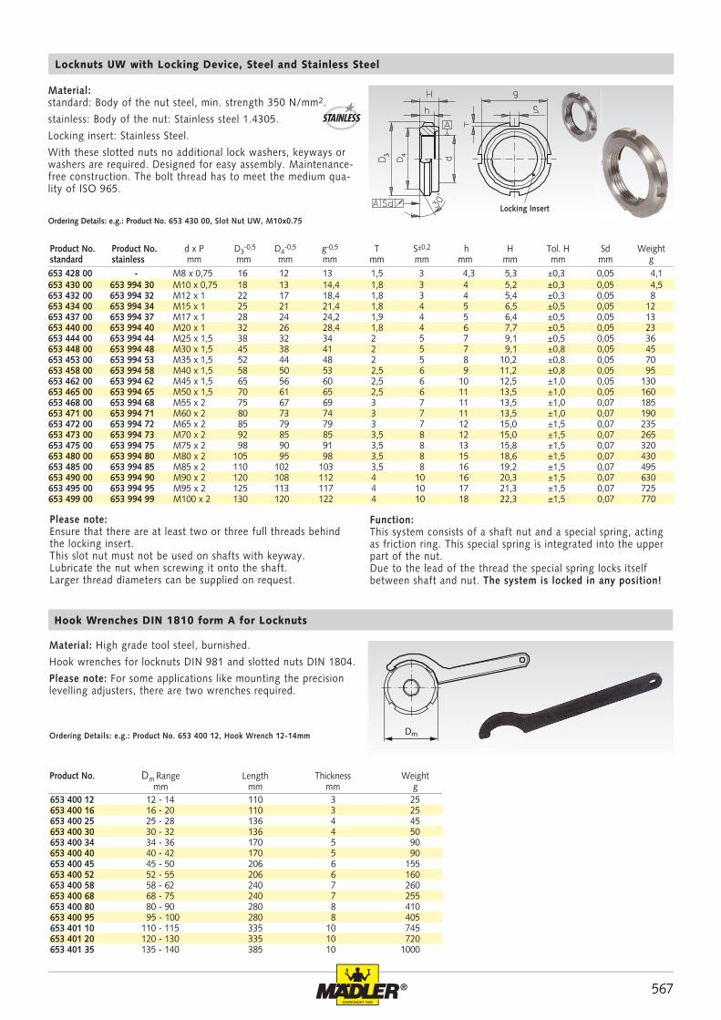
653 428 00 - M8 x 0,75 16 12 13 1,5 3 4,3 5,3 ±0,3 0,05 4,1653 430 00 653 994 30 M10 x 0,75 18 13 14,4 1,8 3 4 5,2 ±0,3 0,05 4,5653 432 00 653 994 32 M12 x 1 22 17 18,4 1,8 3 4 5,4 ±0,3 0,05 8653 434 00 653 994 34 M15 x 1 25 21 21,4 1,8 4 5 6,5 ±0,5 0,05 12653 437 00 653 994 37 M17 x 1 28 24 24,2 1,9 4 5 6,4 ±0,5 0,05 13653 440 00 653 994 40 M20 x 1 32 26 28,4 1,8 4 6 7,7 ±0,5 0,05 23653 444 00 653 994 44 M25 x 1,5 38 32 34 2 5 7 9,1 ±0,5 0,05 36653 448 00 653 994 48 M30 x 1,5 45 38 41 2 5 7 9,1 ±0,8 0,05 45653 453 00 653 994 53 M35 x 1,5 52 44 48 2 5 8 10,2 ±0,8 0,05 70653 458 00 653 994 58 M40 x 1,5 58 50 53 2,5 6 9 11,2 ±0,8 0,05 95653 462 00 653 994 62 M45 x 1,5 65 56 60 2,5 6 10 12,5 ±1,0 0,05 130653 465 00 653 994 65 M50 x 1,5 70 61 65 2,5 6 11 13,5 ±1,0 0,05 160653 468 00 653 994 68 M55 x 2 75 67 69 3 7 11 13,5 ±1,0 0,07 185653 471 00 653 994 71 M60 x 2 80 73 74 3 7 11 13,5 ±1,0 0,07 190653 472 00 653 994 72 M65 x 2 85 79 79 3 7 12 15,0 ±1,5 0,07 235653 473 00 653 994 73 M70 x 2 92 85 85 3,5 8 12 15,0 ±1,5 0,07 265653 475 00 653 994 75 M75 x 2 98 90 91 3,5 8 13 15,8 ±1,5 0,07 320653 480 00 653 994 80 M80 x 2 105 95 98 3,5 8 15 18,6 ±1,5 0,07 430653 485 00 653 994 85 M85 x 2 110 102 103 3,5 8 16 19,2 ±1,5 0,07 495653 490 00 653 994 90 M90 x 2 120 108 112 4 10 16 20,3 ±1,5 0,07 630653 495 00 653 994 95 M95 x 2 125 113 117 4 10 17 21,3 ±1,5 0,07 725653 499 00 653 994 99 M100 x 2 130 120 122 4 10 18 22,3 ±1,5 0,07 770
Product No. Dm Range Length Thickness Weight mm mm mm g
Material: High grade tool steel, burnished.
Hook wrenches for locknuts DIN 981 and slotted nuts DIN 1804.
Please note: For some applications like mounting the precision levelling adjusters, there are two wrenches required.
Ordering Details: e.g.: Product No. 653 400 12, Hook Wrench 12-14mm
Hook Wrenches DIN 1810 form A for Locknuts
Locknuts UW with Locking Device, Steel and Stainless Steel
STAINLESS
Material: standard: Body of the nut steel, min. strength 350 N/mm2.
stainless: Body of the nut: Stainless steel 1.4305.
Locking insert: Stainless Steel.
With these slotted nuts no additional lock washers, keyways or washers are required. Designed for easy assembly. Maintenance-free construction. The bolt thread has to meet the medium qua-lity of ISO 965.
Ordering Details: e.g.: Product No. 653 430 00, Slot Nut UW, M10x0.75
Product No. Product No. d x P D3-0,5 D4
-0,5 g-0,5 T S±0,2 h H Tol. H Sd Weightstandard stainless mm mm mm mm mm mm mm mm mm mm g
Please note:Ensure that there are at least two or three full threads behind the locking insert. This slot nut must not be used on shafts with keyway. Lubricate the nut when screwing it onto the shaft.Larger thread diameters can be supplied on request.
Function:This system consists of a shaft nut and a special spring, acting as friction ring. This special spring is integrated into the upper part of the nut.Due to the lead of the thread the special spring locks itself between shaft and nut. The system is locked in any position!
Locking Insert
568 ®
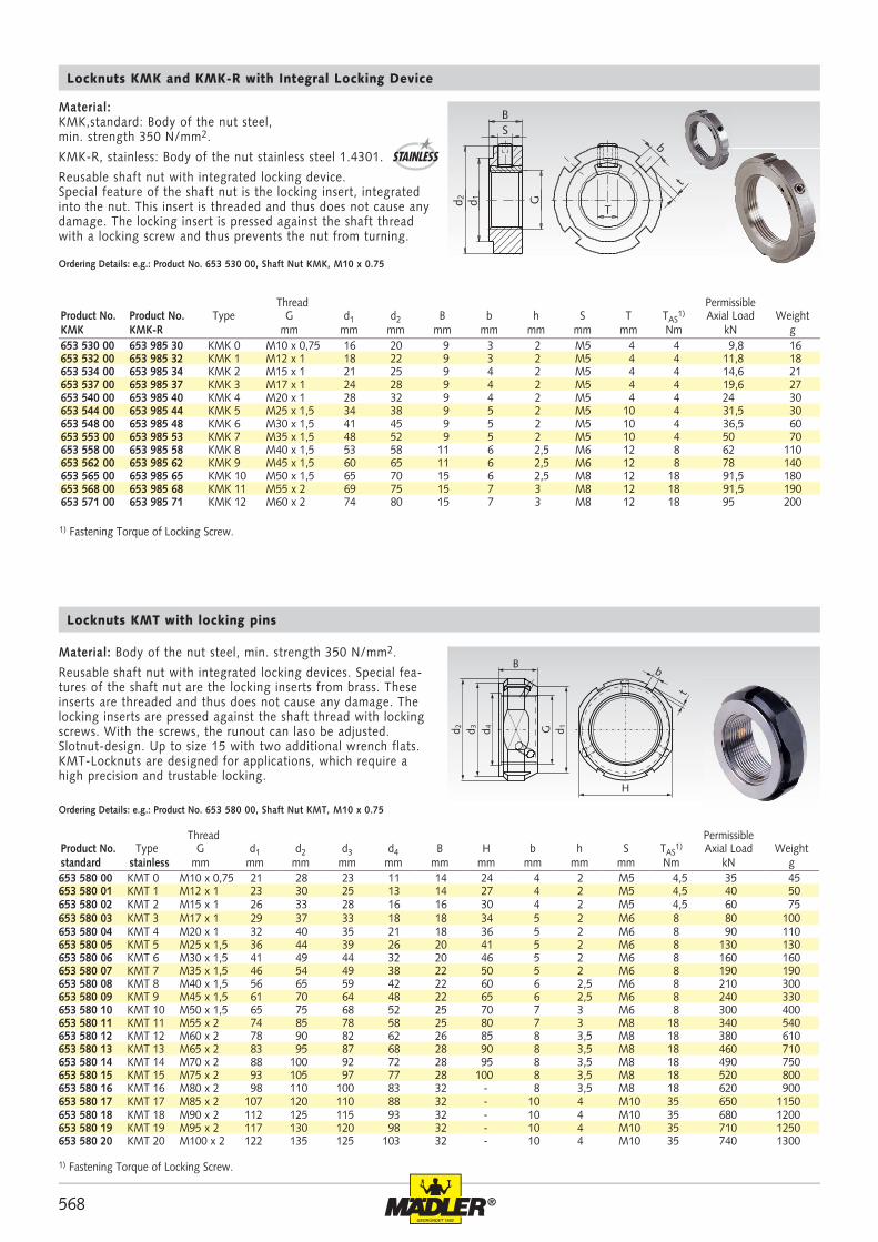
653 580 00 KMT 0 M10 x 0,75 21 28 23 11 14 24 4 2 M5 4,5 35 45653 580 01 KMT 1 M12 x 1 23 30 25 13 14 27 4 2 M5 4,5 40 50653 580 02 KMT 2 M15 x 1 26 33 28 16 16 30 4 2 M5 4,5 60 75653 580 03 KMT 3 M17 x 1 29 37 33 18 18 34 5 2 M6 8 80 100653 580 04 KMT 4 M20 x 1 32 40 35 21 18 36 5 2 M6 8 90 110653 580 05 KMT 5 M25 x 1,5 36 44 39 26 20 41 5 2 M6 8 130 130653 580 06 KMT 6 M30 x 1,5 41 49 44 32 20 46 5 2 M6 8 160 160653 580 07 KMT 7 M35 x 1,5 46 54 49 38 22 50 5 2 M6 8 190 190653 580 08 KMT 8 M40 x 1,5 56 65 59 42 22 60 6 2,5 M6 8 210 300653 580 09 KMT 9 M45 x 1,5 61 70 64 48 22 65 6 2,5 M6 8 240 330653 580 10 KMT 10 M50 x 1,5 65 75 68 52 25 70 7 3 M6 8 300 400653 580 11 KMT 11 M55 x 2 74 85 78 58 25 80 7 3 M8 18 340 540653 580 12 KMT 12 M60 x 2 78 90 82 62 26 85 8 3,5 M8 18 380 610653 580 13 KMT 13 M65 x 2 83 95 87 68 28 90 8 3,5 M8 18 460 710653 580 14 KMT 14 M70 x 2 88 100 92 72 28 95 8 3,5 M8 18 490 750653 580 15 KMT 15 M75 x 2 93 105 97 77 28 100 8 3,5 M8 18 520 800653 580 16 KMT 16 M80 x 2 98 110 100 83 32 - 8 3,5 M8 18 620 900653 580 17 KMT 17 M85 x 2 107 120 110 88 32 - 10 4 M10 35 650 1150653 580 18 KMT 18 M90 x 2 112 125 115 93 32 - 10 4 M10 35 680 1200653 580 19 KMT 19 M95 x 2 117 130 120 98 32 - 10 4 M10 35 710 1250653 580 20 KMT 20 M100 x 2 122 135 125 103 32 - 10 4 M10 35 740 1300
bt
d 2 G d 1d 3 d 4
B
H
BS
d 2
t
b
d 1 G
T
653 530 00 653 985 30 KMK 0 M10 x 0,75 16 20 9 3 2 M5 4 4 9,8 16653 532 00 653 985 32 KMK 1 M12 x 1 18 22 9 3 2 M5 4 4 11,8 18653 534 00 653 985 34 KMK 2 M15 x 1 21 25 9 4 2 M5 4 4 14,6 21653 537 00 653 985 37 KMK 3 M17 x 1 24 28 9 4 2 M5 4 4 19,6 27653 540 00 653 985 40 KMK 4 M20 x 1 28 32 9 4 2 M5 4 4 24 30653 544 00 653 985 44 KMK 5 M25 x 1,5 34 38 9 5 2 M5 10 4 31,5 30653 548 00 653 985 48 KMK 6 M30 x 1,5 41 45 9 5 2 M5 10 4 36,5 60653 553 00 653 985 53 KMK 7 M35 x 1,5 48 52 9 5 2 M5 10 4 50 70653 558 00 653 985 58 KMK 8 M40 x 1,5 53 58 11 6 2,5 M6 12 8 62 110653 562 00 653 985 62 KMK 9 M45 x 1,5 60 65 11 6 2,5 M6 12 8 78 140653 565 00 653 985 65 KMK 10 M50 x 1,5 65 70 15 6 2,5 M8 12 18 91,5 180653 568 00 653 985 68 KMK 11 M55 x 2 69 75 15 7 3 M8 12 18 91,5 190653 571 00 653 985 71 KMK 12 M60 x 2 74 80 15 7 3 M8 12 18 95 200
Ordering Details: e.g.: Product No. 653 530 00, Shaft Nut KMK, M10 x 0.75
Material: KMK,standard: Body of the nut steel, min. strength 350 N/mm2.
KMK-R, stainless: Body of the nut stainless steel 1.4301.
Reusable shaft nut with integrated locking device. Special feature of the shaft nut is the locking insert, integrated into the nut. This insert is threaded and thus does not cause any damage. The locking insert is pressed against the shaft thread with a locking screw and thus prevents the nut from turning.
Locknuts KMK and KMK-R with Integral Locking Device
Locknuts KMT with locking pins
Material: Body of the nut steel, min. strength 350 N/mm2.
Reusable shaft nut with integrated locking devices. Special fea-tures of the shaft nut are the locking inserts from brass. These inserts are threaded and thus does not cause any damage. The locking inserts are pressed against the shaft thread with locking screws. With the screws, the runout can laso be adjusted. Slotnut-design. Up to size 15 with two additional wrench flats. KMT-Locknuts are designed for applications, which require a high precision and trustable locking.
Ordering Details: e.g.: Product No. 653 580 00, Shaft Nut KMT, M10 x 0.75
Thread PermissibleProduct No. Type G d1 d2 d3 d4 B H b h S TAS
1) Axial Load Weightstandard stainless mm mm mm mm mm mm mm mm mm mm Nm kN g
Thread PermissibleProduct No. Product No. Type G d1 d2 B b h S T TAS
1) Axial Load WeightKMK KMK-R mm mm mm mm mm mm mm mm Nm kN g
1) Fastening Torque of Locking Screw.
1) Fastening Torque of Locking Screw.
STAINLESS
569®
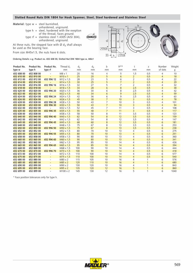
652 608 00 652 808 00 - M8 x 1 20 16 4 5 1,5 0,5 4 10652 610 00 652 810 00 - M10 x 1 25 20 5 6 2 0,5 4 18652 612 00 652 812 00 652 996 12 M12 x 1,5 28 23 5 6 2 0,5 4 22652 614 00 652 814 00 - M14 x 1,5 30 25 5 7 2 0,5 4 29652 616 00 652 816 00 652 996 16 M16 x 1,5 32 27 5 7 2 0,5 4 32652 618 00 652 818 00 - M18 x 1,5 34 28 6 8 2,5 0,5 4 38652 620 00 652 820 00 652 996 20 M20 x 1,5 36 30 6 8 2,5 0,5 4 42652 622 00 652 822 00 - M22 x 1,5 40 34 6 9 2,5 0,5 4 59652 624 00 652 824 00 652 996 24 M24 x 1,5 42 36 6 9 2,5 0,5 4 63652 626 00 652 826 00 - M26 x 1,5 45 38 7 10 3 0,5 4 78652 628 00 652 828 00 652 996 28 M28 x 1,5 50 43 7 10 3 0,5 4 101652 630 00 652 830 00 652 996 30 M30 x 1,5 50 43 7 10 3 0,5 4 94652 632 00 652 832 00 - M32 x 1,5 52 45 7 11 3 0,5 4 108652 635 00 652 835 00 652 996 35 M35 x 1,5 55 48 7 11 3 0,5 4 117652 638 00 652 838 00 - M38 x 1,5 58 50 8 11 3,5 0,5 4 123652 640 00 652 840 00 652 996 40 M40 x 1,5 62 54 8 12 3,5 0,5 4 159652 642 00 652 842 00 - M42 x 1,5 62 54 8 12 3,5 0,5 4 147652 645 00 652 845 00 652 996 45 M45 x 1,5 68 60 8 12 3,5 0,5 6 181652 648 00 652 848 00 - M48 x 1,5 75 67 8 13 3,5 0,5 6 253652 650 00 652 850 00 652 996 50 M50 x 1,5 75 67 8 13 3,5 0,5 6 238652 652 00 652 852 00 - M52 x 1,5 80 70 10 13 4 0,5 6 275652 655 00 652 855 00 652 996 55 M55 x 1,5 80 70 10 13 4 0,5 6 251652 658 00 652 858 00 - M58 x 1,5 90 80 10 13 4 0,5 6 360652 660 00 652 860 00 652 996 60 M60 x 1,5 90 80 10 13 4 0,5 6 341652 662 00 652 862 00 - M62 x 1,5 95 85 10 14 4 0,5 6 426652 665 00 652 865 00 652 996 65 M65 x 1,5 95 85 10 14 4 0,5 6 394652 668 00 652 868 00 - M68 x 1,5 100 90 10 14 4 0,5 6 444652 670 00 652 870 00 652 996 70 M70 x 1,5 100 90 10 14 4 0,5 6 418652 672 00 652 872 00 - M72 x 1,5 110 100 10 14 4 0,5 6 577652 675 00 652 875 00 - M75 x 1,5 110 100 10 14 4 0,5 6 540652 680 00 652 880 00 - M80 x 2 115 105 10 16 4 1 6 576652 685 00 652 885 00 - M85 x 2 120 110 10 16 4 1 6 680652 690 00 652 890 00 - M90 x 2 130 120 10 16 4 1 6 843652 695 00 652 895 00 - M95 x 2 135 120 12 16 5 1 6 860652 699 00 652 899 00 - M100 x 2 145 130 12 16 5 1 6 1040
h
d 3 d 1 d 2
z bt
B
A
IT6 A
IT5 B
*
*
Slotted Round Nuts DIN 1804 for Hook Spanner, Steel, Steel hardened and Stainless Steel
Ordering Details: e.g. Product no. 652 608 00, Slotted Nut DIN 1804 type w, M8x1
STAINLESS
Product No. Product No. Product No. Thread d1 d2 d3 b hh14 t z Number Weighttype w type h type rf mm mm mm mm mm mm mm of slots g
Material: type w = steel burnished, unhardened, unground. type h = steel, hardened with the exeption of the thread, faces ground. type rf = stainless steel 1.4305 (AISI 304), unhardened, unground.
At these nuts, the stepped face with Ø d3 shall always be used as the bearing face.
From size M45x1.5, the nuts have 6 slots.
* Face position tolerances only for type h.
570 ®
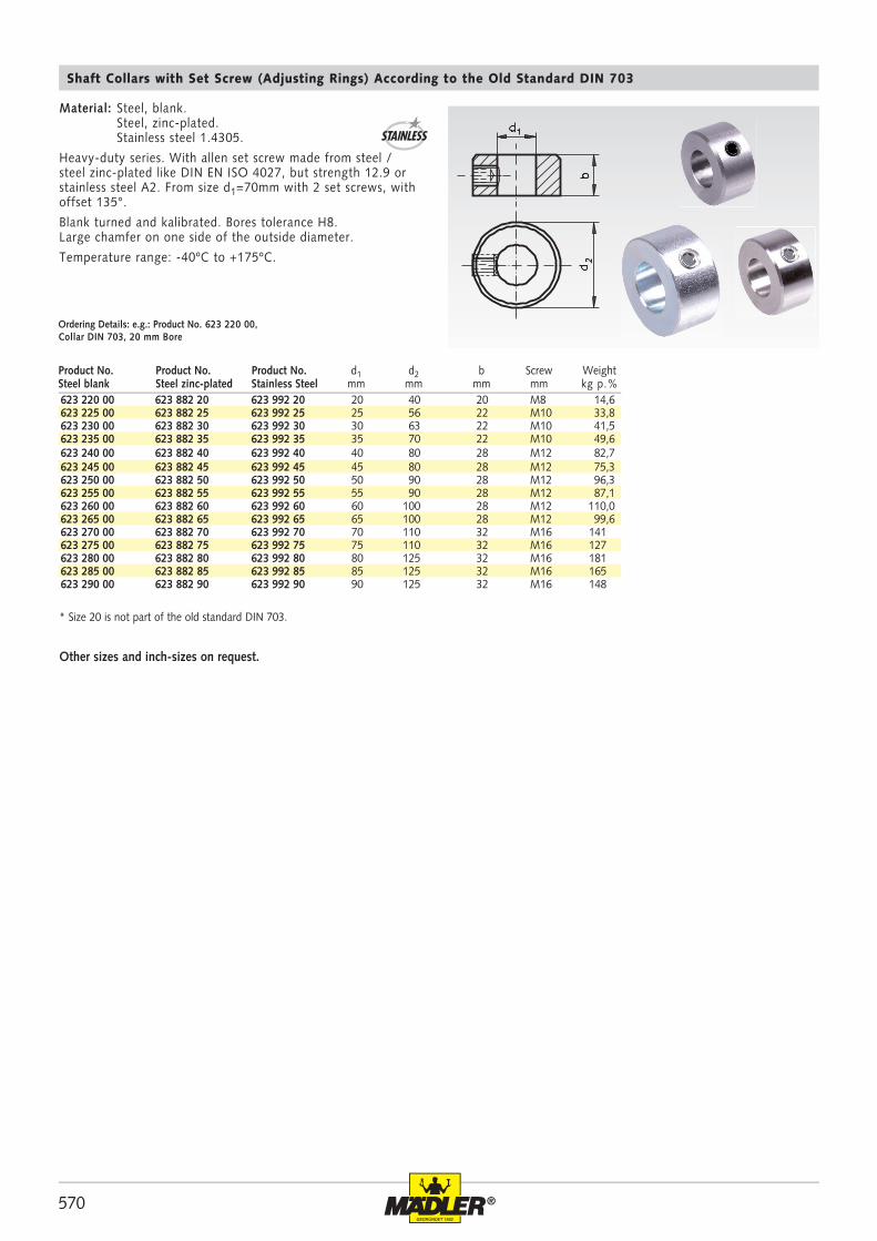
623 220 00 623 882 20 623 992 20 20 40 20 M8 14,6623 225 00 623 882 25 623 992 25 25 56 22 M10 33,8623 230 00 623 882 30 623 992 30 30 63 22 M10 41,5623 235 00 623 882 35 623 992 35 35 70 22 M10 49,6623 240 00 623 882 40 623 992 40 40 80 28 M12 82,7623 245 00 623 882 45 623 992 45 45 80 28 M12 75,3623 250 00 623 882 50 623 992 50 50 90 28 M12 96,3623 255 00 623 882 55 623 992 55 55 90 28 M12 87,1623 260 00 623 882 60 623 992 60 60 100 28 M12 110,0623 265 00 623 882 65 623 992 65 65 100 28 M12 99,6623 270 00 623 882 70 623 992 70 70 110 32 M16 141623 275 00 623 882 75 623 992 75 75 110 32 M16 127623 280 00 623 882 80 623 992 80 80 125 32 M16 181623 285 00 623 882 85 623 992 85 85 125 32 M16 165623 290 00 623 882 90 623 992 90 90 125 32 M16 148
Shaft Collars with Set Screw (Adjusting Rings) According to the Old Standard DIN 703
Ordering Details: e.g.: Product No. 623 220 00, Collar DIN 703, 20 mm Bore
Material: Steel, blank. Steel, zinc-plated. Stainless steel 1.4305.
Heavy-duty series. With allen set screw made from steel / steel zinc-plated like DIN EN ISO 4027, but strength 12.9 or stainless steel A2. From size d1=70mm with 2 set screws, with offset 135°.
Blank turned and kalibrated. Bores tolerance H8. Large chamfer on one side of the outside diameter.
Temperature range: -40ºC to +175ºC.
Other sizes and inch-sizes on request.
* Size 20 is not part of the old standard DIN 703.
Product No. Product No. Product No. d1 d2 b Screw WeightSteel blank Steel zinc-plated Stainless Steel mm mm mm mm kg p.%
STAINLESS
571®
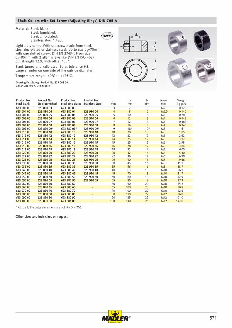
623 003 00 623 890 03 623 880 03 - 3 7 5 M2 0,123623 004 00 623 890 04 623 880 04 623 990 04 4 8 5 M2,5 0,145623 005 00 623 890 05 623 880 05 623 990 05 5 10 6 M3 0,280623 006 00 623 890 06 623 880 06 623 990 06 6 12 8 M4 0,548623 007 00 623 890 07 623 880 07 623 990 07 7 12 8 M4 0,488623 008 00 623 890 08 623 880 08 623 990 08 8 16 8 M4 0,940623 009 00* 623 890 09* 623 880 09* 623 990 09* 9 18* 10* M5 1,51623 010 00 623 890 10 623 880 10 623 990 10 10 20 10 M5 1,85623 012 00 623 890 12 623 880 12 623 990 12 12 22 12 M6 2,52623 014 00 623 890 14 623 880 14 623 990 14 14 25 12 M6 3,17623 015 00 623 890 15 623 880 15 623 990 15 15 25 12 M6 2,98623 016 00 623 890 16 623 880 16 623 990 16 16 28 12 M6 3,84623 018 00 623 890 18 623 880 18 623 990 18 18 32 14 M6 6,00623 020 00 623 890 20 623 880 20 623 990 20 20 32 14 M6 5,30623 022 00 623 890 22 623 880 22 623 990 22 22 36 14 M6 6,90623 025 00 623 890 25 623 880 25 623 990 25 25 40 16 M8 9,56623 030 00 623 890 30 623 880 30 623 990 30 30 45 16 M8 11,1623 035 00 623 890 35 623 880 35 623 990 35 35 56 16 M8 18,7623 040 00 623 890 40 623 880 40 623 990 40 40 63 18 M10 26,1623 045 00 623 890 45 623 880 45 623 990 45 45 70 18 M10 31,7623 050 00 623 890 50 623 880 50 623 990 50 50 80 18 M10 42,9623 055 00 623 890 55 623 880 55 623 990 55 55 80 18 M10 37,3623 060 00 623 890 60 623 880 60 - 60 90 20 M10 55,2623 065 00 623 890 65 623 880 65 - 65 100 20 M10 70,8623 070 00 623 890 70 623 880 70 - 70 100 20 M10 62,6623 080 00 623 890 80 623 880 80 - 80 110 22 M12 76,8623 090 00 623 890 90 623 880 90 - 90 125 22 M12 101,0623 100 00 623 891 00 623 881 00 - 100 140 25 M12 147,0
Material: Steel, blank. Steel, burnished. Steel, zinc-plated. Stainless steel 1.4305.
Light-duty series. With set screw made from steel, steel zinc-plated or stainless steel. Up to size d1=70mm with one slotted screw, DIN EN 27434. From size d1=80mm with 2 allen screws like DIN EN ISO 4027, but strength 12.9, with offset 135°.
Blank turned and kalibrated. Bores tolerance H8. Large chamfer on one side of the outside diameter.
Temperature range: -40ºC to +175ºC.
Shaft Collars with Set Screw (Adjusting Rings) DIN 705 A
Ordering Details: e.g.: Product No. 623 003 00, Collar DIN 705 A, 3 mm Bore
* At size 9, the outer dimensions are not like DIN 705.
Other sizes and inch-sizes on request.
STAINLESS
Product No. Product No. Product No. Product No. d1 d2 b Screw WeightSteel blank Steel burnished Steel zinc-plated Stainless Steel mm mm mm mm kg p.%
572 ®
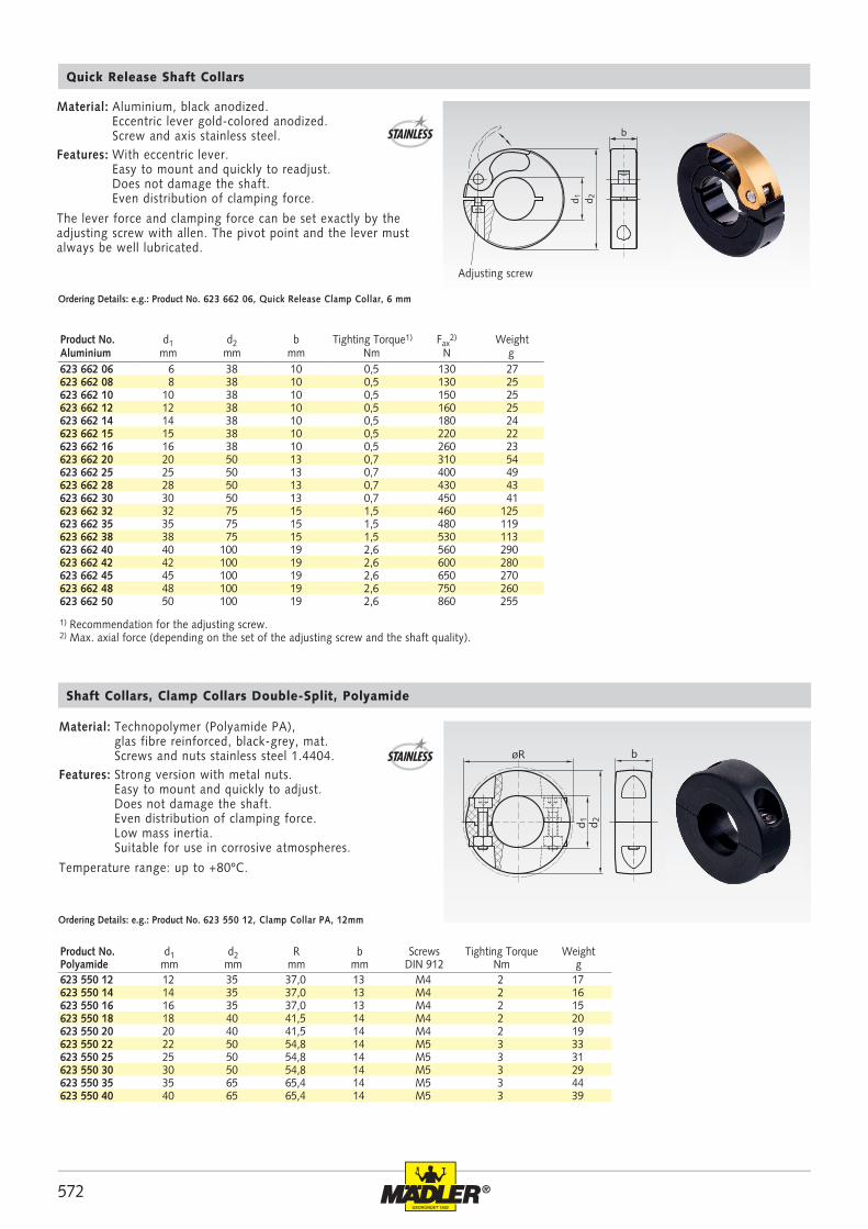
623 550 12 12 35 37,0 13 M4 2 17623 550 14 14 35 37,0 13 M4 2 16623 550 16 16 35 37,0 13 M4 2 15623 550 18 18 40 41,5 14 M4 2 20623 550 20 20 40 41,5 14 M4 2 19623 550 22 22 50 54,8 14 M5 3 33623 550 25 25 50 54,8 14 M5 3 31623 550 30 30 50 54,8 14 M5 3 29623 550 35 35 65 65,4 14 M5 3 44623 550 40 40 65 65,4 14 M5 3 39
623 662 06 6 38 10 0,5 130 27623 662 08 8 38 10 0,5 130 25623 662 10 10 38 10 0,5 150 25623 662 12 12 38 10 0,5 160 25623 662 14 14 38 10 0,5 180 24623 662 15 15 38 10 0,5 220 22623 662 16 16 38 10 0,5 260 23623 662 20 20 50 13 0,7 310 54623 662 25 25 50 13 0,7 400 49623 662 28 28 50 13 0,7 430 43623 662 30 30 50 13 0,7 450 41623 662 32 32 75 15 1,5 460 125623 662 35 35 75 15 1,5 480 119623 662 38 38 75 15 1,5 530 113623 662 40 40 100 19 2,6 560 290623 662 42 42 100 19 2,6 600 280623 662 45 45 100 19 2,6 650 270623 662 48 48 100 19 2,6 750 260623 662 50 50 100 19 2,6 860 255
d 1 d 2
b
d 1 d 2
bøR
Ordering Details: e.g.: Product No. 623 550 12, Clamp Collar PA, 12mm
Shaft Collars, Clamp Collars Double-Split, Polyamide
Material: Technopolymer (Polyamide PA), glas fibre reinforced, black-grey, mat. Screws and nuts stainless steel 1.4404.Features: Strong version with metal nuts. Easy to mount and quickly to adjust. Does not damage the shaft. Even distribution of clamping force. Low mass inertia. Suitable for use in corrosive atmospheres.
Temperature range: up to +80ºC.
STAINLESS
Ordering Details: e.g.: Product No. 623 662 06, Quick Release Clamp Collar, 6 mm
Quick Release Shaft Collars
1) Recommendation for the adjusting screw. 2) Max. axial force (depending on the set of the adjusting screw and the shaft quality).
Product No. d1 d2 b Tighting Torque1) Fax2) Weight
Aluminium mm mm mm Nm N g
Product No. d1 d2 R b Screws Tighting Torque WeightPolyamide mm mm mm mm DIN 912 Nm g
Material: Aluminium, black anodized. Eccentric lever gold-colored anodized. Screw and axis stainless steel.Features: With eccentric lever. Easy to mount and quickly to readjust. Does not damage the shaft. Even distribution of clamping force.
The lever force and clamping force can be set exactly by the adjusting screw with allen. The pivot point and the lever must always be well lubricated.
Adjusting screw
STAINLESS
573®
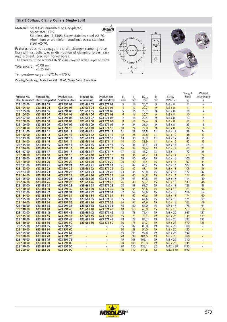
623 103 00 623 881 03 623 991 03 623 661 03 623 671 03 3 16 20,7 9 M3 x 8 11 4623 104 00 623 881 04 623 991 04 623 661 04 623 671 04 4 16 20,7 9 M3 x 8 11 4623 105 00 623 881 05 623 991 05 623 661 05 623 671 05 5 16 20,7 9 M3 x 8 10 4623 106 00 623 881 06 623 991 06 623 661 06 623 671 06 6 16 20,7 9 M3 x 8 10 4623 107 00 623 881 07 623 991 07 623 661 07 623 671 07 7 18 22,4 9 M3 x 8 13 5623 108 00 623 881 08 623 991 08 623 661 08 623 671 08 8 18 22,4 9 M3 x 8 12 5623 109 00 623 881 09 623 991 09 623 661 09 623 671 09 9 24 26,0 9 M3 x 8 23 8623 110 00 623 881 10 623 991 10 623 661 10 623 671 10 10 24 26,0 9 M3 x 8 22 8623 111 00 623 881 11 623 991 11 623 661 11 623 671 11 11 28 31,8 11 M4 x 12 39 14623 112 00 623 881 12 623 991 12 623 661 12 623 671 12 12 28 31,8 11 M4 x 12 38 13623 113 00 623 881 13 623 991 13 623 661 13 623 671 13 13 30 33,9 11 M4 x 12 43 15623 114 00 623 881 14 623 991 14 623 661 14 623 671 14 14 30 33,9 11 M4 x 12 42 15623 115 00 623 881 15 623 991 15 623 661 15 623 671 15 15 34 39,4 13 M5 x 14 65 23623 116 00 623 881 16 623 991 16 623 661 16 623 671 16 16 34 39,4 13 M5 x 14 63 22623 117 00 623 881 17 623 991 17 623 661 17 623 671 17 17 36 41,2 13 M5 x 14 72 25623 118 00 623 881 18 623 991 18 623 661 18 623 671 18 18 36 41,2 13 M5 x 14 69 24623 119 00 623 881 19 623 991 19 623 661 19 623 671 19 19 40 46,4 15 M5 x 14 100 35623 120 00 623 881 20 623 991 20 623 661 20 623 671 20 20 40 46,4 15 M6 x 16 97 34623 121 00 623 881 21 623 991 21 623 661 21 623 671 21 21 42 48,1 15 M6 x 16 107 37623 122 00 623 881 22 623 991 22 623 661 22 623 671 22 22 42 48,1 15 M6 x 16 103 36623 123 00 623 881 23 623 991 23 623 661 23 623 671 23 23 45 50,8 15 M6 x 16 122 42623 124 00 623 881 24 623 991 24 623 661 24 623 671 24 24 45 50,8 15 M6 x 16 117 40623 125 00 623 881 25 623 991 25 623 661 25 623 671 25 25 45 50,8 15 M6 x 16 114 40623 126 00 623 881 26 623 991 26 623 661 26 623 671 26 26 48 53,7 15 M6 x 18 133 46623 128 00 623 881 28 623 991 28 623 661 28 623 671 28 28 48 53,7 15 M6 x 18 123 43623 130 00 623 881 30 623 991 30 623 661 30 623 671 30 30 54 58,6 15 M6 x 18 163 56623 132 00 623 881 32 623 991 32 623 661 32 623 671 32 32 54 58,6 15 M6 x 18 156 54623 134 00 623 881 34 623 991 34 623 661 34 623 671 34 34 57 61,6 15 M6 x 18 174 60623 135 00 623 881 35 623 991 35 623 661 35 623 671 35 35 57 61,6 15 M6 x 18 171 59623 136 00 623 881 36 623 991 36 623 661 36 623 671 36 36 57 61,6 15 M6 x 18 163 56623 138 00 623 881 38 623 991 38 623 661 38 623 671 38 38 60 65,0 15 M6 x 18 178 61623 140 00 623 881 40 623 991 40 623 661 40 623 671 40 40 60 65,0 15 M6 x 18 163 56623 142 00 623 881 42 623 991 42 623 661 42 623 671 42 42 73 79,4 19 M8 x 25 367 127623 145 00 623 881 45 623 991 45 623 661 45 623 671 45 45 73 79,4 19 M8 x 25 344 119623 148 00 623 881 48 623 991 48 623 661 48 623 671 48 48 78 84,2 19 M8 x 25 392 135623 150 00 623 881 50 623 991 50 623 661 50 623 671 50 50 78 84,2 19 M8 x 25 370 128623 155 00 623 881 55 623 991 55 - - 55 82 88,8 19 M8 x 25 380 -623 160 00 623 881 60 623 991 60 - - 60 88 94,0 19 M8 x 25 425 -623 165 00 623 881 65 623 991 65 - - 65 93 99,8 19 M8 x 25 450 -623 170 00 623 881 70 623 991 70 - - 70 98 104,5 19 M8 x 25 480 -623 175 00 623 881 75 623 991 75 - - 75 103 109,1 19 M8 x 25 510 -623 180 00 623 881 80 623 991 80 - - 80 108 113,8 19 M8 x 25 535 -623 190 00 623 881 90 623 991 90 - - 90 130 138,1 32 M12 x 30 1730 -623 200 00 623 882 00 623 992 00 - - 100 140 147,6 32 M12 x 30 1890 -
Rb
d1
d2
STAINLESS
Ordering Details: e.g.: Product No. 623 103 00, Clamp Collar, 3 mm Bore
Material: Steel C45 burnished or zinc-plated, Screw steel 12.9. Stainless steel 1.4305, Screw stainless steel A2-70. Aluminium or aluminium anodized, screw stainless steel A2-70.
Features: does not damage the shaft, stronger clamping force than with set collars, even distribution of clamping forces, easy readjustment, precision honed bores.The threads of the screws DIN 912 are covered with a layer of nylon.
Tolerance b: +0.08 mm -0.25 mm
Temperature range: -40ºC to +175ºC.
Shaft Collars, Clamp Collars Single-Split
Weight WeightProduct No. Product No. Product No. Product No. Product No. d1 d2 Rmax. b Screw Steel AluminiumSteel burnished Steel zinc-plated Stainless Steel Aluminium Alu anodized mm mm mm mm DIN912 g g
574 ®
623 403 00 623 884 03 623 994 03 623 664 03 623 674 03 3 16 20,7 9 M3 x 8 12 4623 404 00 623 884 04 623 994 04 623 664 04 623 674 04 4 16 20,7 9 M3 x 8 11 4623 405 00 623 884 05 623 994 05 623 664 05 623 674 05 5 16 20,7 9 M3 x 8 11 4623 406 00 623 884 06 623 994 06 623 664 06 623 674 06 6 16 20,7 9 M3 x 8 10 3623 407 00 623 884 07 623 994 07 623 664 07 623 674 07 7 18 22,4 9 M3 x 8 13 4623 408 00 623 884 08 623 994 08 623 664 08 623 674 08 8 18 22,4 9 M3 x 8 12 4623 409 00 623 884 09 623 994 09 623 664 09 623 674 09 9 24 26,0 9 M3 x 10 25 9623 410 00 623 884 10 623 994 10 623 664 10 623 674 10 10 24 26,0 9 M3 x 10 24 8623 411 00 623 884 11 623 994 11 623 664 11 623 674 11 11 28 31,8 11 M4 x 12 40 14623 412 00 623 884 12 623 994 12 623 664 12 623 674 12 12 28 31,8 11 M4 x 12 39 13623 413 00 623 884 13 623 994 13 623 664 13 623 674 13 13 30 33,9 11 M4 x 14 45 16623 414 00 623 884 14 623 994 14 623 664 14 623 674 14 14 30 33,9 11 M4 x 14 43 15623 415 00 623 884 15 623 994 15 623 664 15 623 674 15 15 34 39,4 13 M5 x 16 68 23623 416 00 623 884 16 623 994 16 623 664 16 623 674 16 16 34 39,4 13 M5 x 16 65 22623 417 00 623 884 17 623 994 17 623 664 17 623 674 17 17 36 41,2 13 M5 x 16 74 26623 418 00 623 884 18 623 994 18 623 664 18 623 674 18 18 36 41,2 13 M5 x 16 71 24623 419 00 623 884 19 623 994 19 623 664 19 623 674 19 19 40 46,4 15 M6 x 16 104 36623 420 00 623 884 20 623 994 20 623 664 20 623 674 20 20 40 46,4 15 M6 x 16 101 35623 421 00 623 884 21 623 994 21 623 664 21 623 674 21 21 42 48,1 15 M6 x 16 113 39623 422 00 623 884 22 623 994 22 623 664 22 623 674 22 22 42 48,1 15 M6 x 16 107 37623 423 00 623 884 23 623 994 23 623 664 23 623 674 23 23 45 50,8 15 M6 x 16 127 44623 424 00 623 884 24 623 994 24 623 664 24 623 674 24 24 45 50,8 15 M6 x 16 122 42623 425 00 623 884 25 623 994 25 623 664 25 623 674 25 25 45 50,8 15 M6 x 16 120 41623 426 00 623 884 26 623 994 26 623 664 26 623 674 26 26 48 53,7 15 M6 x 16 139 48623 428 00 623 884 28 623 994 28 623 664 28 623 674 28 28 48 53,7 15 M6 x 16 128 44623 430 00 623 884 30 623 994 30 623 664 30 623 674 30 30 54 58,6 15 M6 x 18 171 59623 432 00 623 884 32 623 994 32 623 664 32 623 674 32 32 54 58,6 15 M6 x 18 161 56623 434 00 623 884 34 623 994 34 623 664 34 623 674 34 34 57 61,6 15 M6 x 18 181 62623 435 00 623 884 35 623 994 35 623 664 35 623 674 35 35 57 61,6 15 M6 x 18 172 60623 436 00 623 884 36 623 994 36 623 664 36 623 674 36 36 57 61,6 15 M6 x 18 169 59623 438 00 623 884 38 623 994 38 623 664 38 623 674 38 38 60 65,0 15 M6 x 18 183 63623 440 00 623 884 40 623 994 40 623 664 40 623 674 40 40 60 65,0 15 M6 x 18 172 59623 442 00 623 884 42 623 994 42 623 664 42 623 674 42 42 73 79,4 19 M8 x 25 383 132623 445 00 623 884 45 623 994 45 623 664 45 623 674 45 45 73 79,4 19 M8 x 25 360 124623 448 00 623 884 48 623 994 48 623 664 48 623 674 48 48 78 84,2 19 M8 x 25 414 143623 450 00 623 884 50 623 994 50 623 664 50 623 674 50 50 78 84,2 19 M8 x 25 386 133623 455 00 623 884 55 623 994 55 - - 55 82 88,8 19 M8 x 25 395 -623 460 00 623 884 60 623 994 60 - - 60 88 94,0 19 M8 x 25 440 -623 465 00 623 884 65 623 994 65 - - 65 93 99,8 19 M8 x 25 465 -623 470 00 623 884 70 623 994 70 - - 70 98 104,5 19 M8 x 25 495 -623 475 00 623 884 75 623 994 75 - - 75 103 109,1 19 M8 x 25 525 -623 480 00 623 884 80 623 994 80 - - 80 108 113,8 19 M8 x 25 550 -623 490 00 623 884 90 623 994 90 - - 90 130 138,1 32 M12 x 30 1730 -623 500 00 623 885 00 623 995 00 - - 100 140 147,6 32 M12 x 30 1890 -
R
d1
d2
bSTAINLESS
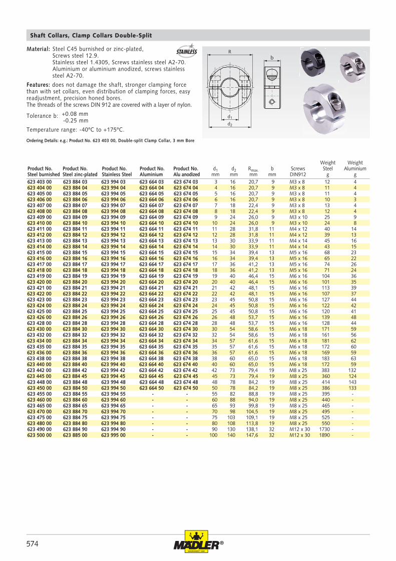
Ordering Details: e.g.: Product No. 623 403 00, Double-split Clamp Collar, 3 mm Bore
Shaft Collars, Clamp Collars Double-Split
Weight WeightProduct No. Product No. Product No. Product No. Product No. d1 d2 Rmax. b Screws Steel AluminiumSteel burnished Steel zinc-plated Stainless Steel Aluminium Alu anodized mm mm mm mm DIN912 g g
Material: Steel C45 burnished or zinc-plated, Screws steel 12.9. Stainless steel 1.4305, Screws stainless steel A2-70. Aluminium or aluminium anodized, screws stainless steel A2-70.
Features: does not damage the shaft, stronger clamping force than with set collars, even distribution of clamping forces, easy readjustment, precision honed bores.The threads of the screws DIN 912 are covered with a layer of nylon.
Tolerance b: +0.08 mm -0.25 mm
Temperature range: -40ºC to +175ºC.
575®
624 106 00 624 991 06 6+0,05 16 20,1 20 5,2 M3 x 8 2,1 1,1 20624 108 00 624 991 08 8+0,07 18 21,3 20 6,0 M3 x 8 2,1 1,1 24624 110 00 624 991 10 10+0,07 24 25,6 20 8,5 M3 x 8 2,1 1,1 48624 112 00 624 991 12 12+0,07 28 31,7 24 10,0 M4 x 12 4,6 2,5 78624 116 00 624 991 16 16+0,07 34 38,5 29 12,0 M5 x 14 9,5 5,4 130624 120 00 624 991 20 20+0,07 40 46,3 33 14,5 M6 x 16 16 9,6 202624 125 00 624 991 25 25+0,07 45 50,6 33 17,0 M6 x 16 16 9,6 240624 130 00 624 991 30 30+0,12 54 58,6 33 21,5 M6 x 18 16 9,6 342624 140 00 624 991 40 40+0,12 60 65,0 33 25,0 M6 x 18 16 9,6 344624 150 00 624 991 50 50+0,12 78 84,2 41 32,0 M8 x 25 17 13,6 772
624 406 00 624 994 06 6+0,05 16 20,1 20 5,2 M3 x 8 2,1 1,1 20624 408 00 624 994 08 8+0,07 18 21,3 20 6,0 M3 x 8 2,1 1,1 24624 410 00 624 994 10 10+0,07 24 25,6 20 8,5 M3 x 8 2,1 1,1 44624 412 00 624 994 12 12+0,07 28 31,7 24 10,0 M4 x 12 4,6 2,5 76624 416 00 624 994 16 16+0,07 34 38,5 29 12,0 M5 x 14 9,5 5,4 126624 420 00 624 994 20 20+0,07 40 46,3 33 14,5 M6 x 16 16 9,6 194624 425 00 624 994 25 25+0,07 45 50,6 33 17,0 M6 x 16 16 9,6 228624 430 00 624 994 30 30+0,12 54 58,6 33 21,5 M6 x 18 16 9,6 326624 440 00 624 994 40 40+0,12 60 65,0 33 25,0 M6 x 18 16 9,6 326624 450 00 624 994 50 50+0,12 78 84,2 41 32,0 M8 x 25 17 13,6 740
Ra b
d1
d2
Raa b
d1
d2
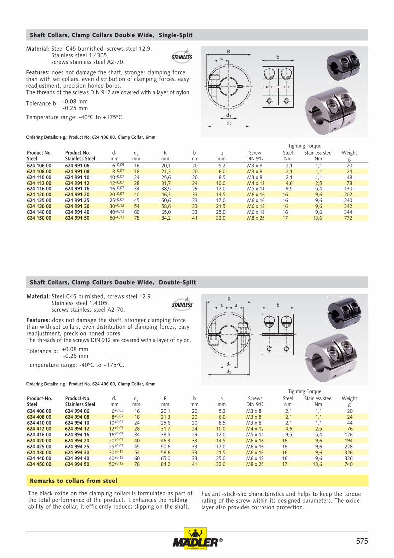
has anti-stick-slip characteristics and helps to keep the torque rating of the screw within its designed parameters. The oxide layer also provides corrosion protection.
The black oxide on the clamping collars is formulated as part of the total performance of the product. It enhances the holding ability of the collar, it efficiently reduces slipping on the shaft,
Remarks to collars from steel
Material: Steel C45 burnished, screws steel 12.9. Stainless steel 1.4305, screws stainless steel A2-70.
Features: does not damage the shaft, stronger clamping force than with set collars, even distribution of clamping forces, easy readjustment, precision honed bores.The threads of the screws DIN 912 are covered with a layer of nylon.
Tolerance b: +0.08 mm -0.25 mm
Temperature range: -40ºC to +175ºC.
Shaft Collars, Clamp Collars Double Wide, Single-Split
Ordering Details: e.g.: Product No. 624 106 00, Clamp Collar, 6mm
Tighting TorqueProduct No. Product No. d1 d2 R b a Screw Steel Stainless steel WeightSteel Stainless Steel mm mm mm mm mm DIN 912 Nm Nm g
Tighting TorqueProduct-No. Product-No. d1 d2 R b a Screws Steel Stainless steel WeightSteel Stainless Steel mm mm mm mm mm DIN 912 Nm Nm g
Ordering Details: e.g.: Product No. 624 406 00, Clamp Collar, 6mm
Shaft Collars, Clamp Collars Double Wide, Double-Split
STAINLESS
Material: Steel C45 burnished, screws steel 12.9. Stainless steel 1.4305, screws stainless steel A2-70.
Features: does not damage the shaft, stronger clamping force than with set collars, even distribution of clamping forces, easy readjustment, precision honed bores.The threads of the screws DIN 912 are covered with a layer of nylon.
Tolerance b: +0.08 mm -0.25 mm
Temperature range: -40ºC to +175ºC.
STAINLESS
576 ®
Rb
d1
d2
b
B 1 B 2
m
623 110 00B1 623 991 10B1 623 110 00B2 623 991 10B2 10 28 - 9 M3 x 10 19 3,5 M3 3,0 M2,5 32623 112 00B1 623 991 12B1 623 112 00B2 623 991 12B2 12 30 31,8 11 M4 x 12 21 4,5 M4 3,5 M3 43623 114 00B1 623 991 14B1 623 114 00B2 623 991 14B2 14 32 33,9 11 M4 x 14 23 4,5 M4 3,5 M3 48623 115 00B1 623 991 15B1 623 115 00B2 623 991 15B2 15 36 39,4 13 M5 x 16 25,5 5,5 M5 4,5 M4 71623 116 00B1 623 991 16B1 623 116 00B2 623 991 16B2 16 38 39,4 13 M5 x 16 27 5,5 M5 4,5 M4 81623 118 00B1 623 991 18B1 623 118 00B2 623 991 18B2 18 40 41,2 13 M5 x 16 29 5,5 M5 4,5 M4 89623 120 00B1 623 991 20B1 623 120 00B2 623 991 20B2 20 42 46,4 15 M6 x 16 31 5,5 M5 4,5 M4 107623 122 00B1 623 991 22B1 623 122 00B2 623 991 22B2 22 46 48,1 15 M6 x 16 34 6,5 M6 5,5 M5 128623 125 00B1 623 991 25B1 623 125 00B2 623 991 25B2 25 48 50,8 15 M6 x 16 36,5 6,5 M6 5,5 M5 132623 128 00B1 623 991 28B1 623 128 00B2 623 991 28B2 28 54 - 15 M6 x 16 41 6,5 M6 5,5 M5 172623 130 00B1 623 991 30B1 623 130 00B2 623 991 30B2 30 56 58,6 15 M6 x 18 43 6,5 M6 5,5 M5 176623 132 00B1 623 991 32B1 623 132 00B2 623 991 32B2 32 58 58,6 15 M6 x 18 45 6,5 M6 5,5 M5 190623 135 00B1 623 991 35B1 623 135 00B2 623 991 35B2 35 60 61,6 15 M6 x 18 47,5 6,5 M6 5,5 M5 196623 140 00B1 623 991 40B1 623 140 00B2 623 991 40B2 40 66 - 15 M6 x 18 53 6,5 M6 5,5 M5 225623 145 00B1 623 991 45B1 623 145 00B2 623 991 45B2 45 76 79,4 19 M8 x 25 60,5 8,5 M8 6,5 M6 379623 150 00B1 623 991 50B1 623 150 00B2 623 991 50B2 50 82 84,2 19 M8 x 25 66 8,5 M8 6,5 M6 428
623 410 00B1 623 994 10B1 623 410 00B2 623 994 10B2 10 28 - 9 M3 x 10 19 3,5 M3 3,0 M2,5 34623 412 00B1 623 994 12B1 623 412 00B2 623 994 12B2 12 30 31,8 11 M4 x 12 21 4,5 M4 3,5 M3 44623 414 00B1 623 994 14B1 623 414 00B2 623 994 14B2 14 32 33,9 11 M4 x 14 23 4,5 M4 3,5 M3 49623 415 00B1 623 994 15B1 623 415 00B2 623 994 15B2 15 36 39,4 13 M5 x 16 25,5 5,5 M5 4,5 M4 74623 416 00B1 623 994 16B1 623 416 00B2 623 994 16B2 16 38 39,4 13 M5 x 16 27 5,5 M5 4,5 M4 83623 418 00B1 623 994 18B1 623 418 00B2 623 994 18B2 18 40 41,2 13 M5 x 16 29 5,5 M5 4,5 M4 91623 420 00B1 623 994 20B1 623 420 00B2 623 994 20B2 20 42 46,4 15 M6 x 16 31 5,5 M5 4,5 M4 111623 422 00B1 623 994 22B1 623 422 00B2 623 994 22B2 22 46 48,1 15 M6 x 16 34 6,5 M6 5,5 M5 132623 425 00B1 623 994 25B1 623 425 00B2 623 994 25B2 25 48 50,8 15 M6 x 16 36,5 6,5 M6 5,5 M5 138623 428 00B1 623 994 28B1 623 428 00B2 623 994 28B2 28 54 - 15 M6 x 16 41 6,5 M6 5,5 M5 177623 430 00B1 623 994 30B1 623 430 00B2 623 994 30B2 30 56 58,6 15 M6 x 18 43 6,5 M6 5,5 M5 184623 432 00B1 623 994 32B1 623 432 00B2 623 994 32B2 32 58 58,6 15 M6 x 18 45 6,5 M6 5,5 M5 195623 435 00B1 623 994 35B1 623 435 00B2 623 994 35B2 35 60 61,6 15 M6 x 18 47,5 6,5 M6 5,5 M5 197623 440 00B1 623 994 40B1 623 440 00B2 623 994 40B2 40 66 - 15 M6 x 18 53 6,5 M6 5,5 M5 234623 445 00B1 623 994 45B1 623 445 00B2 623 994 45B2 45 76 79,4 19 M8 x 25 60,5 8,5 M8 6,5 M6 395623 450 00B1 623 994 50B1 623 450 00B2 623 994 50B2 50 82 84,2 19 M8 x 25 66 8,5 M8 6,5 M6 444
R
d1
d2
b b
B 1 B 2
m
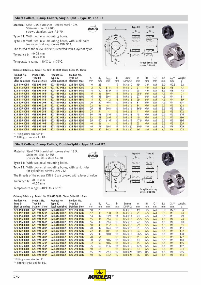
Shaft Collars, Clamp Collars, Single-Split - Type B1 and B2
Ordering Details: e.g.: Product No. 623 110 00B1 Clamp Collar B1, 10mm
Ordering Details: e.g.: Product No. 623 410 00B1, Clamp Collar B1, 10mm
Shaft Collars, Clamp Collars, Double-Split - Type B1 and B2
STAINLESS
Material: Steel C45 burnished, screws steel 12.9. Stainless steel 1.4305, screws stainless steel A2-70.
Type B1: With two axial mounting bores.
Type B2: With two axial mounting bores, with sunk holes for cylindrical screws DIN 912.
The threads of the screws DIN 912 are covered with a layer of nylon.
Tolerance b: +0.08 mm -0.25 mm
Temperature range: -40ºC to +175ºC.
STAINLESS
Product No. Product No. Product No. Product No.Type B1 Type B1 Type B2 Type B2 d1 d2 Rmax. b Scew m B1 G1* B2 G2** WeightSteel burnished Stainless Steel Steel burnished Stainless Steel mm mm mm mm DIN912 mm mm mm mm mm g
Product No. Product No. Product No. Product No.Type B1 Type B1 Type B2 Type B2 d1 d2 Rmax. b Screws m B1 G1* B2 G2** WeightSteel burnished Stainless Steel Steel burnished Stainless Steel mm mm mm mm DIN912 mm mm mm mm mm g
Material: Steel C45 burnished, screws steel 12.9. Stainless steel 1.4305, screws stainless steel A2-70.
Type B1: With two axial mounting bores.
Type B2: With two axial mounting bores, with sunk holes for cylindrical cap screws DIN 912.
The thread of the screw DIN 912 is covered with a layer of nylon.
Tolerance b: +0.08 mm -0.25 mm
Temperature range: -40ºC to +175ºC.
Type B1 Type B2
for cylindrical cap screws DIN 912
* Fitting screw size for B1.** Fitting screw size for B2.
* Fitting screw size for B1.** Fitting screw size for B2.
Type B1 Type B2
for cylindrical cap screws DIN 912
577®
Rb
d1
d2
G
m
623 110 00GA 623 991 10GA 10 28 - 9 M3 x 10 19 M3 33623 112 00GA 623 991 12GA 12 30 31,8 11 M4 x 12 21 M4 44623 114 00GA 623 991 14GA 14 32 33,9 11 M4 x 14 23 M4 49623 115 00GA 623 991 15GA 15 36 39,4 13 M5 x 16 25,5 M5 73623 116 00GA 623 991 16GA 16 38 39,4 13 M5 x 16 27 M5 83623 118 00GA 623 991 18GA 18 40 41,2 13 M5 x 16 29 M5 90623 120 00GA 623 991 20GA 20 42 46,4 15 M6 x 16 31 M5 107623 122 00GA 623 991 22GA 22 46 48,1 15 M6 x 16 34 M6 130623 125 00GA 623 991 25GA 25 48 50,8 15 M6 x 16 36,5 M6 135623 128 00GA 623 991 28GA 28 54 - 15 M6 x 16 41 M6 174623 130 00GA 623 991 30GA 30 56 58,6 15 M6 x 18 43 M6 178623 132 00GA 623 991 32GA 32 58 58,6 15 M6 x 18 45 M6 192623 135 00GA 623 991 35GA 35 60 61,6 15 M6 x 18 47,5 M6 198623 140 00GA 623 991 40GA 40 66 - 15 M6 x 18 53 M6 228623 145 00GA 623 991 45GA 45 76 79,4 19 M8 x 25 60,5 M8 384623 150 00GA 623 991 50GA 50 82 84,2 19 M8 x 25 66 M8 433
623 410 00GA 623 994 10GA 10 28 - 9 M3 x 10 19 M3 35623 412 00GA 623 994 12GA 12 30 31,8 11 M4 x 12 21 M4 45623 414 00GA 623 994 14GA 14 32 33,9 11 M4 x 14 23 M4 50623 415 00GA 623 994 15GA 15 36 39,4 13 M5 x 16 25,5 M5 76623 416 00GA 623 994 16GA 16 38 39,4 13 M5 x 16 27 M5 85623 418 00GA 623 994 18GA 18 40 41,2 13 M5 x 16 29 M5 92623 420 00GA 623 994 20GA 20 42 46,4 15 M6 x 16 31 M5 111623 422 00GA 623 994 22GA 22 46 48,1 15 M6 x 16 34 M6 134623 425 00GA 623 994 25GA 25 48 50,8 15 M6 x 16 36,5 M6 141623 428 00GA 623 994 28GA 28 54 - 15 M6 x 16 41 M6 179623 430 00GA 623 994 30GA 30 56 58,6 15 M6 x 18 43 M6 186623 432 00GA 623 994 32GA 32 58 58,6 15 M6 x 18 45 M6 197623 435 00GA 623 994 35GA 35 60 61,6 15 M6 x 18 47,5 M6 199623 440 00GA 623 994 40GA 40 66 - 15 M6 x 18 53 M6 237623 445 00GA 623 994 45GA 45 76 79,4 19 M8 x 25 60,5 M8 400623 450 00GA 623 994 50GA 50 82 84,2 19 M8 x 25 66 M8 449
R
d1
d2
b
G
m
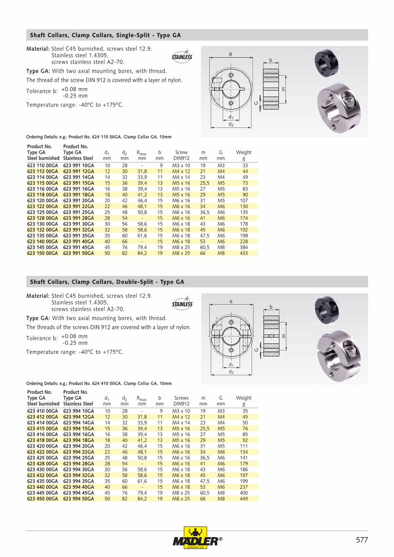
Material: Steel C45 burnished, screws steel 12.9. Stainless steel 1.4305, screws stainless steel A2-70.
Type GA: With two axial mounting bores, with thread.
The thread of the screw DIN 912 is covered with a layer of nylon.
Tolerance b: +0.08 mm -0.25 mm
Temperature range: -40ºC to +175ºC.
Ordering Details: e.g.: Product No. 624 110 00GA, Clamp Collar GA, 10mm
Ordering Details: e.g.: Product No. 624 410 00GA, Clamp Collar GA, 10mm
STAINLESS
STAINLESS
Product No. Product No.Type GA Type GA d1 d2 Rmax. b Screw m G WeightSteel burnished Stainless Steel mm mm mm mm DIN912 mm mm g
Product No. Product No.Type GA Type GA d1 d2 Rmax. b Screws m G WeightSteel burnished Stainless Steel mm mm mm mm DIN912 mm mm g
Shaft Collars, Clamp Collars, Single-Split - Type GA
Shaft Collars, Clamp Collars, Double-Split - Type GA
Material: Steel C45 burnished, screws steel 12.9. Stainless steel 1.4305, screws stainless steel A2-70.
Type GA: With two axial mounting bores, with thread.
The threads of the screws DIN 912 are covered with a layer of nylon.
Tolerance b: +0.08 mm -0.25 mm
Temperature range: -40ºC to +175ºC.
578 ®
R
d1
d2
ml
t
h
b
G
d1
d2
t
h
R
ml
b
G
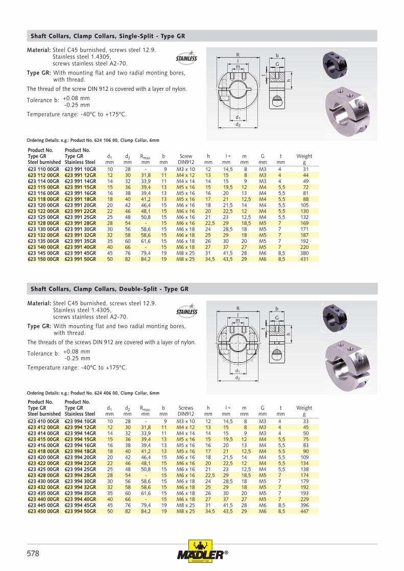
623 410 00GR 623 994 10GR 10 28 - 9 M3 x 10 12 14,5 8 M3 4 33623 412 00GR 623 994 12GR 12 30 31,8 11 M4 x 12 13 15 8 M3 4 45623 414 00GR 623 994 14GR 14 32 33,9 11 M4 x 14 14 15 9 M3 4 50623 415 00GR 623 994 15GR 15 36 39,4 13 M5 x 16 15 19,5 12 M4 5,5 75623 416 00GR 623 994 16GR 16 38 39,4 13 M5 x 16 16 20 13 M4 5,5 83623 418 00GR 623 994 18GR 18 40 41,2 13 M5 x 16 17 21 12,5 M4 5,5 90623 420 00GR 623 994 20GR 20 42 46,4 15 M6 x 16 18 21,5 14 M4 5,5 109623 422 00GR 623 994 22GR 22 46 48,1 15 M6 x 16 20 22,5 12 M4 5,5 134623 425 00GR 623 994 25GR 25 48 50,8 15 M6 x 16 21 23 12,5 M4 5,5 138623 428 00GR 623 994 28GR 28 54 - 15 M6 x 16 22,5 29 18,5 M5 7 174623 430 00GR 623 994 30GR 30 56 58,6 15 M6 x 18 24 28,5 18 M5 7 179623 432 00GR 623 994 32GR 32 58 58,6 15 M6 x 18 25 29 18 M5 7 192623 435 00GR 623 994 35GR 35 60 61,6 15 M6 x 18 26 30 20 M5 7 193623 440 00GR 623 994 40GR 40 66 - 15 M6 x 18 27 37 27 M5 7 229623 445 00GR 623 994 45GR 45 76 79,4 19 M8 x 25 31 41,5 28 M6 8,5 396623 450 00GR 623 994 50GR 50 82 84,2 19 M8 x 25 34,5 43,5 29 M6 8,5 447
623 110 00GR 623 991 10GR 10 28 - 9 M3 x 10 12 14,5 8 M3 4 31623 112 00GR 623 991 12GR 12 30 31,8 11 M4 x 12 13 15 8 M3 4 44623 114 00GR 623 991 14GR 14 32 33,9 11 M4 x 14 14 15 9 M3 4 49623 115 00GR 623 991 15GR 15 36 39,4 13 M5 x 16 15 19,5 12 M4 5,5 72623 116 00GR 623 991 16GR 16 38 39,4 13 M5 x 16 16 20 13 M4 5,5 81623 118 00GR 623 991 18GR 18 40 41,2 13 M5 x 16 17 21 12,5 M4 5,5 88623 120 00GR 623 991 20GR 20 42 46,4 15 M6 x 16 18 21,5 14 M4 5,5 105623 122 00GR 623 991 22GR 22 46 48,1 15 M6 x 16 20 22,5 12 M4 5,5 130623 125 00GR 623 991 25GR 25 48 50,8 15 M6 x 16 21 23 12,5 M4 5,5 132623 128 00GR 623 991 28GR 28 54 - 15 M6 x 16 22,5 29 18,5 M5 7 169623 130 00GR 623 991 30GR 30 56 58,6 15 M6 x 18 24 28,5 18 M5 7 171623 132 00GR 623 991 32GR 32 58 58,6 15 M6 x 18 25 29 18 M5 7 187623 135 00GR 623 991 35GR 35 60 61,6 15 M6 x 18 26 30 20 M5 7 192623 140 00GR 623 991 40GR 40 66 - 15 M6 x 18 27 37 27 M5 7 220623 145 00GR 623 991 45GR 45 76 79,4 19 M8 x 25 31 41,5 28 M6 8,5 380623 150 00GR 623 991 50GR 50 82 84,2 19 M8 x 25 34,5 43,5 29 M6 8,5 431
Material: Steel C45 burnished, screws steel 12.9. Stainless steel 1.4305, screws stainless steel A2-70.
Type GR: With mounting flat and two radial monting bores, with thread.
The thread of the screw DIN 912 is covered with a layer of nylon.
Tolerance b: +0.08 mm -0.25 mm
Temperature range: -40ºC to +175ºC.
Ordering Details: e.g.: Product No. 624 106 00, Clamp Collar, 6mm
Ordering Details: e.g.: Product No. 624 406 00, Clamp Collar, 6mm
STAINLESS
STAINLESS
Product No. Product No.Type GR Type GR d1 d2 Rmax. b Screw h l ≈ m G t WeightSteel burnished Stainless Steel mm mm mm mm DIN912 mm mm mm mm mm g
Product No. Product No.Type GR Type GR d1 d2 Rmax. b Screws h l ≈ m G t WeightSteel burnished Stainless Steel mm mm mm mm DIN912 mm mm mm mm mm g
Shaft Collars, Clamp Collars, Single-Split - Type GR
Shaft Collars, Clamp Collars, Double-Split - Type GR
Material: Steel C45 burnished, screws steel 12.9. Stainless steel 1.4305, screws stainless steel A2-70.
Type GR: With mounting flat and two radial monting bores, with thread.
The threads of the screws DIN 912 are covered with a layer of nylon.
Tolerance b: +0.08 mm -0.25 mm
Temperature range: -40ºC to +175ºC.
579®
Rb
d1
d2
a
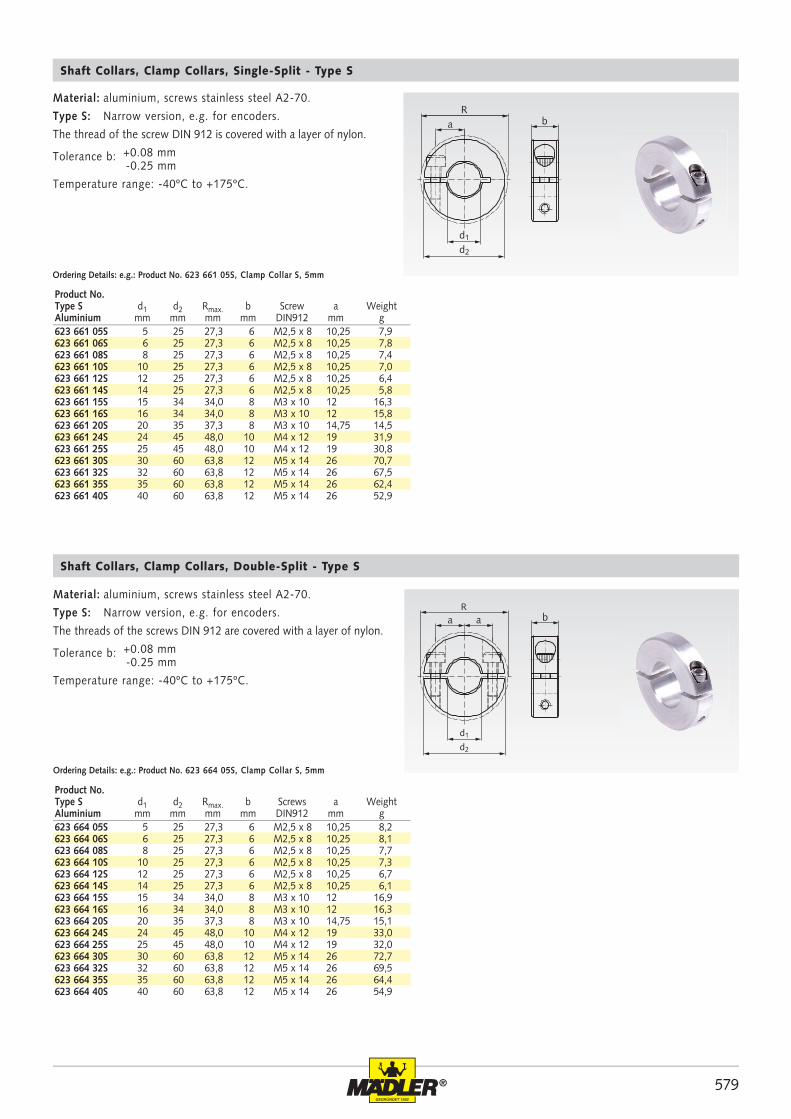
623 661 05S 5 25 27,3 6 M2,5 x 8 10,25 7,9623 661 06S 6 25 27,3 6 M2,5 x 8 10,25 7,8623 661 08S 8 25 27,3 6 M2,5 x 8 10,25 7,4623 661 10S 10 25 27,3 6 M2,5 x 8 10,25 7,0623 661 12S 12 25 27,3 6 M2,5 x 8 10,25 6,4623 661 14S 14 25 27,3 6 M2,5 x 8 10,25 5,8623 661 15S 15 34 34,0 8 M3 x 10 12 16,3623 661 16S 16 34 34,0 8 M3 x 10 12 15,8623 661 20S 20 35 37,3 8 M3 x 10 14,75 14,5623 661 24S 24 45 48,0 10 M4 x 12 19 31,9623 661 25S 25 45 48,0 10 M4 x 12 19 30,8623 661 30S 30 60 63,8 12 M5 x 14 26 70,7623 661 32S 32 60 63,8 12 M5 x 14 26 67,5623 661 35S 35 60 63,8 12 M5 x 14 26 62,4623 661 40S 40 60 63,8 12 M5 x 14 26 52,9
R
d1
d2
ba a
623 664 05S 5 25 27,3 6 M2,5 x 8 10,25 8,2623 664 06S 6 25 27,3 6 M2,5 x 8 10,25 8,1623 664 08S 8 25 27,3 6 M2,5 x 8 10,25 7,7623 664 10S 10 25 27,3 6 M2,5 x 8 10,25 7,3623 664 12S 12 25 27,3 6 M2,5 x 8 10,25 6,7623 664 14S 14 25 27,3 6 M2,5 x 8 10,25 6,1623 664 15S 15 34 34,0 8 M3 x 10 12 16,9623 664 16S 16 34 34,0 8 M3 x 10 12 16,3623 664 20S 20 35 37,3 8 M3 x 10 14,75 15,1623 664 24S 24 45 48,0 10 M4 x 12 19 33,0623 664 25S 25 45 48,0 10 M4 x 12 19 32,0623 664 30S 30 60 63,8 12 M5 x 14 26 72,7623 664 32S 32 60 63,8 12 M5 x 14 26 69,5623 664 35S 35 60 63,8 12 M5 x 14 26 64,4623 664 40S 40 60 63,8 12 M5 x 14 26 54,9
Material: aluminium, screws stainless steel A2-70.
Type S: Narrow version, e.g. for encoders.
The thread of the screw DIN 912 is covered with a layer of nylon.
Tolerance b: +0.08 mm -0.25 mm
Temperature range: -40ºC to +175ºC.
Ordering Details: e.g.: Product No. 623 661 05S, Clamp Collar S, 5mm
Ordering Details: e.g.: Product No. 623 664 05S, Clamp Collar S, 5mm
Product No.Type S d1 d2 Rmax. b Screw a WeightAluminium mm mm mm mm DIN912 mm g
Product No.Type S d1 d2 Rmax. b Screws a WeightAluminium mm mm mm mm DIN912 mm g
Shaft Collars, Clamp Collars, Single-Split - Type S
Shaft Collars, Clamp Collars, Double-Split - Type S
Material: aluminium, screws stainless steel A2-70.
Type S: Narrow version, e.g. for encoders.
The threads of the screws DIN 912 are covered with a layer of nylon.
Tolerance b: +0.08 mm -0.25 mm
Temperature range: -40ºC to +175ºC.
580 ®
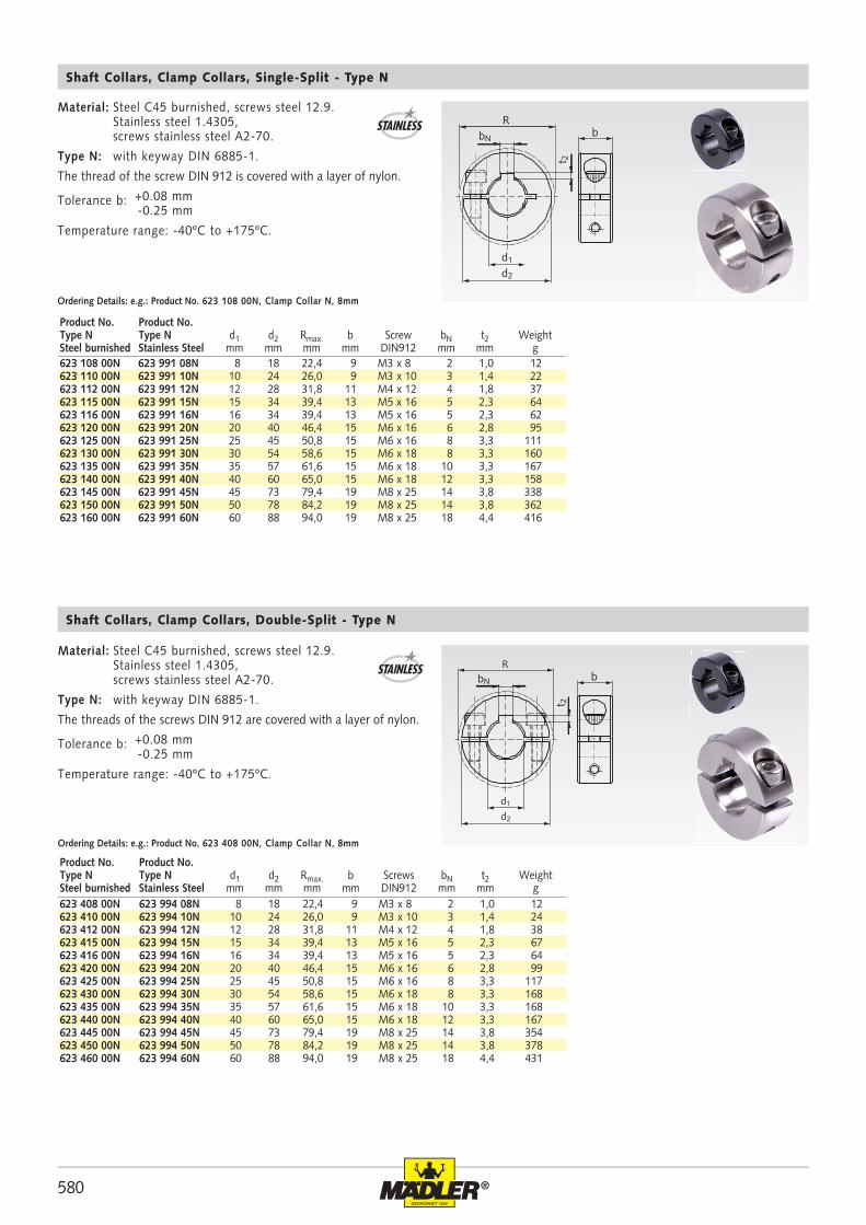
Rb
d1
d2
t 2
bN
623 108 00N 623 991 08N 8 18 22,4 9 M3 x 8 2 1,0 12623 110 00N 623 991 10N 10 24 26,0 9 M3 x 10 3 1,4 22623 112 00N 623 991 12N 12 28 31,8 11 M4 x 12 4 1,8 37623 115 00N 623 991 15N 15 34 39,4 13 M5 x 16 5 2,3 64623 116 00N 623 991 16N 16 34 39,4 13 M5 x 16 5 2,3 62623 120 00N 623 991 20N 20 40 46,4 15 M6 x 16 6 2,8 95623 125 00N 623 991 25N 25 45 50,8 15 M6 x 16 8 3,3 111623 130 00N 623 991 30N 30 54 58,6 15 M6 x 18 8 3,3 160623 135 00N 623 991 35N 35 57 61,6 15 M6 x 18 10 3,3 167623 140 00N 623 991 40N 40 60 65,0 15 M6 x 18 12 3,3 158623 145 00N 623 991 45N 45 73 79,4 19 M8 x 25 14 3,8 338623 150 00N 623 991 50N 50 78 84,2 19 M8 x 25 14 3,8 362623 160 00N 623 991 60N 60 88 94,0 19 M8 x 25 18 4,4 416
623 408 00N 623 994 08N 8 18 22,4 9 M3 x 8 2 1,0 12623 410 00N 623 994 10N 10 24 26,0 9 M3 x 10 3 1,4 24623 412 00N 623 994 12N 12 28 31,8 11 M4 x 12 4 1,8 38623 415 00N 623 994 15N 15 34 39,4 13 M5 x 16 5 2,3 67623 416 00N 623 994 16N 16 34 39,4 13 M5 x 16 5 2,3 64623 420 00N 623 994 20N 20 40 46,4 15 M6 x 16 6 2,8 99623 425 00N 623 994 25N 25 45 50,8 15 M6 x 16 8 3,3 117623 430 00N 623 994 30N 30 54 58,6 15 M6 x 18 8 3,3 168623 435 00N 623 994 35N 35 57 61,6 15 M6 x 18 10 3,3 168623 440 00N 623 994 40N 40 60 65,0 15 M6 x 18 12 3,3 167623 445 00N 623 994 45N 45 73 79,4 19 M8 x 25 14 3,8 354623 450 00N 623 994 50N 50 78 84,2 19 M8 x 25 14 3,8 378623 460 00N 623 994 60N 60 88 94,0 19 M8 x 25 18 4,4 431
R
d1
d2
b
t 2
bN
Material: Steel C45 burnished, screws steel 12.9. Stainless steel 1.4305, screws stainless steel A2-70.
Type N: with keyway DIN 6885-1.
The thread of the screw DIN 912 is covered with a layer of nylon.
Tolerance b: +0.08 mm -0.25 mm
Temperature range: -40ºC to +175ºC.
Ordering Details: e.g.: Product No. 623 108 00N, Clamp Collar N, 8mm
Ordering Details: e.g.: Product No. 623 408 00N, Clamp Collar N, 8mm
STAINLESS
STAINLESS
Product No. Product No.Type N Type N d1 d2 Rmax. b Screw bN t2 WeightSteel burnished Stainless Steel mm mm mm mm DIN912 mm mm g
Product No. Product No.Type N Type N d1 d2 Rmax. b Screws bN t2 WeightSteel burnished Stainless Steel mm mm mm mm DIN912 mm mm g
Shaft Collars, Clamp Collars, Single-Split - Type N
Shaft Collars, Clamp Collars, Double-Split - Type N
Material: Steel C45 burnished, screws steel 12.9. Stainless steel 1.4305, screws stainless steel A2-70.
Type N: with keyway DIN 6885-1.
The threads of the screws DIN 912 are covered with a layer of nylon.
Tolerance b: +0.08 mm -0.25 mm
Temperature range: -40ºC to +175ºC.
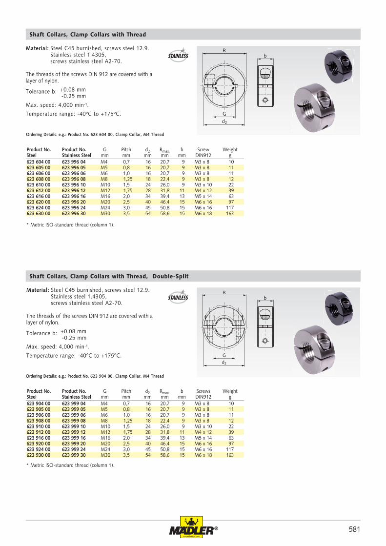
581®
Rb
Gd2
623 604 00 623 996 04 M4 0,7 16 20,7 9 M3 x 8 10623 605 00 623 996 05 M5 0,8 16 20,7 9 M3 x 8 11623 606 00 623 996 06 M6 1,0 16 20,7 9 M3 x 8 11623 608 00 623 996 08 M8 1,25 18 22,4 9 M3 x 8 12623 610 00 623 996 10 M10 1,5 24 26,0 9 M3 x 10 22623 612 00 623 996 12 M12 1,75 28 31,8 11 M4 x 12 39623 616 00 623 996 16 M16 2,0 34 39,4 13 M5 x 14 63623 620 00 623 996 20 M20 2,5 40 46,4 15 M6 x 16 97623 624 00 623 996 24 M24 3,0 45 50,8 15 M6 x 16 117623 630 00 623 996 30 M30 3,5 54 58,6 15 M6 x 18 163
R
G
d2
b
623 904 00 623 999 04 M4 0,7 16 20,7 9 M3 x 8 10623 905 00 623 999 05 M5 0,8 16 20,7 9 M3 x 8 11623 906 00 623 999 06 M6 1,0 16 20,7 9 M3 x 8 11623 908 00 623 999 08 M8 1,25 18 22,4 9 M3 x 8 12623 910 00 623 999 10 M10 1,5 24 26,0 9 M3 x 10 22623 912 00 623 999 12 M12 1,75 28 31,8 11 M4 x 12 39623 916 00 623 999 16 M16 2,0 34 39,4 13 M5 x 14 63623 920 00 623 999 20 M20 2,5 40 46,4 15 M6 x 16 97623 924 00 623 999 24 M24 3,0 45 50,8 15 M6 x 16 117623 930 00 623 999 30 M30 3,5 54 58,6 15 M6 x 18 163
Ordering Details: e.g.: Product No. 623 604 00, Clamp Collar, M4 Thread
Material: Steel C45 burnished, screws steel 12.9. Stainless steel 1.4305, screws stainless steel A2-70.
The threads of the screws DIN 912 are covered with a layer of nylon.
Tolerance b: +0.08 mm -0.25 mm
Max. speed: 4,000 min-1.
Temperature range: -40ºC to +175ºC.
Shaft Collars, Clamp Collars with Thread
* Metric ISO-standard thread (column 1).
STAINLESS
Ordering Details: e.g.: Product No. 623 904 00, Clamp Collar, M4 Thread
Shaft Collars, Clamp Collars with Thread, Double-Split
STAINLESS
* Metric ISO-standard thread (column 1).
Product No. Product No. G Pitch d2 Rmax. b Screw WeightSteel Stainless Steel mm mm mm mm mm DIN912 g
Product No. Product No. G Pitch d2 Rmax. b Screws WeightSteel Stainless Steel mm mm mm mm mm DIN912 g
Material: Steel C45 burnished, screws steel 12.9. Stainless steel 1.4305, screws stainless steel A2-70.
The threads of the screws DIN 912 are covered with a layer of nylon.
Tolerance b: +0.08 mm -0.25 mm
Max. speed: 4,000 min-1.
Temperature range: -40ºC to +175ºC.
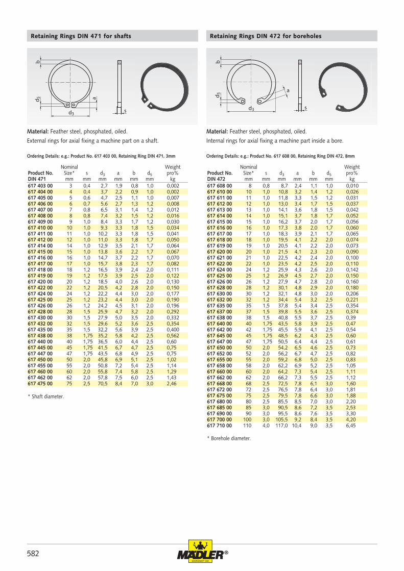
582 ®
617 403 00 3 0,4 2,7 1,9 0,8 1,0 0,002617 404 00 4 0,4 3,7 2,2 0,9 1,0 0,002617 405 00 5 0,6 4,7 2,5 1,1 1,0 0,007617 406 00 6 0,7 5,6 2,7 1,3 1,2 0,008617 407 00 7 0,8 6,5 3,1 1,4 1,2 0,012617 408 00 8 0,8 7,4 3,2 1,5 1,2 0,016617 409 00 9 1,0 8,4 3,3 1,7 1,2 0,030617 410 00 10 1,0 9,3 3,3 1,8 1,5 0,034617 411 00 11 1,0 10,2 3,3 1,8 1,5 0,041617 412 00 12 1,0 11,0 3,3 1,8 1,7 0,050617 414 00 14 1,0 12,9 3,5 2,1 1,7 0,064617 415 00 15 1,0 13,8 3,6 2,2 1,7 0,067617 416 00 16 1,0 14,7 3,7 2,2 1,7 0,070617 417 00 17 1,0 15,7 3,8 2,3 1,7 0,082617 418 00 18 1,2 16,5 3,9 2,4 2,0 0,111617 419 00 19 1,2 17,5 3,9 2,5 2,0 0,122617 420 00 20 1,2 18,5 4,0 2,6 2,0 0,130617 422 00 22 1,2 20,5 4,2 2,8 2,0 0,150617 424 00 24 1,2 22,2 4,4 3,0 2,0 0,177617 425 00 25 1,2 23,2 4,4 3,0 2,0 0,190617 426 00 26 1,2 24,2 4,5 3,1 2,0 0,196617 428 00 28 1,5 25,9 4,7 3,2 2,0 0,292617 430 00 30 1,5 27,9 5,0 3,5 2,0 0,332617 432 00 32 1,5 29,6 5,2 3,6 2,5 0,354617 435 00 35 1,5 32,2 5,6 3,9 2,5 0,400617 438 00 38 1,75 35,2 5,8 4,2 2,5 0,562617 440 00 40 1,75 36,5 6,0 4,4 2,5 0,60617 445 00 45 1,75 41,5 6,7 4,7 2,5 0,75617 447 00 47 1,75 43,5 6,8 4,9 2,5 0,75617 450 00 50 2,0 45,8 6,9 5,1 2,5 1,02617 455 00 55 2,0 50,8 7,2 5,4 2,5 1,14617 460 00 60 2,0 55,8 7,4 5,8 2,5 1,29617 462 00 62 2,0 57,8 7,5 6,0 2,5 1,43617 475 00 75 2,5 70,5 8,4 7,0 3,0 2,46
617 608 00 8 0,8 8,7 2,4 1,1 1,0 0,010617 610 00 10 1,0 10,8 3,2 1,4 1,2 0,026617 611 00 11 1,0 11,8 3,3 1,5 1,2 0,031617 612 00 12 1,0 13,0 3,4 1,7 1,5 0,037617 613 00 13 1,0 14,1 3,6 1,8 1,5 0,042617 614 00 14 1,0 15,1 3,7 1,8 1,7 0,052617 615 00 15 1,0 16,2 3,7 2,0 1,7 0,056617 616 00 16 1,0 17,3 3,8 2,0 1,7 0,060617 617 00 17 1,0 18,3 3,9 2,1 1,7 0,065617 618 00 18 1,0 19,5 4,1 2,2 2,0 0,074617 619 00 19 1,0 20,5 4,1 2,2 2,0 0,073617 620 00 20 1,0 21,5 4,1 2,3 2,0 0,090617 621 00 21 1,0 22,5 4,2 2,4 2,0 0,100617 622 00 22 1,0 23,5 4,2 2,5 2,0 0,110617 624 00 24 1,2 25,9 4,3 2,6 2,0 0,142617 625 00 25 1,2 26,9 4,5 2,7 2,0 0,150617 626 00 26 1,2 27,9 4,7 2,8 2,0 0,160617 628 00 28 1,2 30,1 4,8 2,9 2,0 0,180617 630 00 30 1,2 32,1 4,8 3,0 2,0 0,206617 632 00 32 1,2 34,4 5,4 3,2 2,5 0,221617 635 00 35 1,5 37,8 5,4 3,4 2,5 0,354617 637 00 37 1,5 39,8 5,5 3,6 2,5 0,374617 638 00 38 1,5 40,8 5,5 3,7 2,5 0,39617 640 00 40 1,75 43,5 5,8 3,9 2,5 0,47617 642 00 42 1,75 45,5 5,9 4,1 2,5 0,54617 645 00 45 1,75 48,5 6,2 4,3 2,5 0,60617 647 00 47 1,75 50,5 6,4 4,4 2,5 0,61617 650 00 50 2,0 54,2 6,5 4,6 2,5 0,73617 652 00 52 2,0 56,2 6,7 4,7 2,5 0,82617 655 00 55 2,0 59,2 6,8 5,0 2,5 0,83617 658 00 58 2,0 62,2 6,9 5,2 2,5 1,05617 660 00 60 2,0 64,2 7,3 5,4 2,5 1,11617 662 00 62 2,0 66,2 7,3 5,5 2,5 1,12617 668 00 68 2,5 72,5 7,8 6,1 3,0 1,60617 672 00 72 2,5 76,5 7,8 6,4 3,0 1,81617 675 00 75 2,5 79,5 7,8 6,6 3,0 1,88617 680 00 80 2,5 85,5 8,5 7,0 3,0 2,20617 685 00 85 3,0 90,5 8,6 7,2 3,5 2,53617 690 00 90 3,0 95,5 8,6 7,6 3,5 3,30617 700 00 100 3,0 105,5 9,2 8,4 3,5 4,20617 710 00 110 4,0 117,0 10,4 9,0 3,5 6,45
d3
bd 5 a
s d3
bd 5
s
a
Retaining Rings DIN 471 for shafts
Material: Feather steel, phosphated, oiled.
External rings for axial fixing a machine part on a shaft.
Ordering Details: e.g.: Product No. 617 403 00, Retaining Ring DIN 471, 3mm Ordering Details: e.g.: Product No. 617 608 00, Retaining Ring DIN 472, 8mm
Retaining Rings DIN 472 for boreholes
Material: Feather steel, phosphated, oiled.
Internal rings for axial fixing a machine part inside a bore.
Nominal Weight Product No. Size* s d3 a b d5 pro% DIN 471 mm mm mm mm mm mm kg
Nominal Weight Product No. Size* s d3 a b d5 pro% DIN 472 mm mm mm mm mm mm kg
* Shaft diameter.
* Borehole diameter.
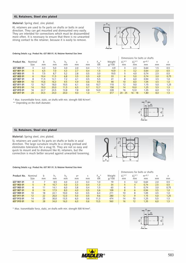
583®
637 800 01 3 4,3 5,0 3,0 2,0 0,4 1,1 4,9 3 2,3 0,64 1,5 0,5637 801 01 4 6,5 7,0 4,3 2,7 0,4 1,5 10,9 4 3,2 0,64 2,0 0,5637 803 01 5 7,5 8,7 5,2 2,8 0,5 3,0 19,5 5 4,0 0,74 2,5 0,5637 805 01 6 10,4 11,5 6,8 3,5 0,5 4,9 33 6 5,0 0,74 3,0 0,75637 807 01 8 11,5 12,1 7,2 4,1 0,5 5,5 41 8 6,0 0,94 3,5 1,0637 809 01 10 15,6 16,3 9,5 5,9 0,6 9,5 90 10 8,0 1,05 4,5 1,0637 811 01 12 16,7 18,0 10,5 6,1 0,6 10,7 110 12 9,0 1,15 5,0 1,25637 813 01 14 19,0 20,0 11,5 6,5 0,7 12,7 158 14 10,0 1,25 5,5 1,5637 815 01 16 22,7 23,5 13,8 7,8 0,8 14,0 228 16 12,0 1,35 6,0 1,5637 817 01 24 34,5 24,0 20,0 9,0 1,0 ** 617 20 - 25 16 - 18 1,80 8,0 1,5
637 901 01 4 7 8,5 4,0 2,3 0,3 1,0 19 4 3,2 0,64 2,0 0,5637 903 01 5 9 10,7 5,0 3,3 0,4 1,3 34 5 4 0,74 2,5 0,5637 905 01 6 11 14,1 6,0 3,8 0,4 1,5 63 6 5 0,74 3,0 0,75637 907 01 8 14 17,5 8,0 4,0 0,5 3,6 109 8 6 0,94 3,5 1,0637 909 01 10 18 22,1 10,0 5,0 0,5 6,4 211 10 8 1,05 4,5 1,0637 911 01 12 22 26,0 12,0 5,0 0,5 9,6 280 12 9 1,15 5,0 1,25637 913 01 14 25 30,0 13,5 6,0 0,6 11,3 474 14 10 1,25 5,5 1,5637 915 01 16 28 34,0 16,0 6,0 0,6 13,5 563 16 12 1,35 6,0 1,5
b
h 2
h 1
a
s
h 2
h 1
b
s
a
n
z
m
d 1d 2
n
z
m
d 1d 2
SL Retainers, Steel zinc plated
Ordering Details: e.g.: Product No. 637 901 01, SL Retainer Nominal Size 4mm
Material: Spring steel, zinc plated.
KL retainers are used to fix parts on shafts or bolts in axial direction. They can get mounted and dismounted very easily. They are intended for connections which must be disassembled more often. It is necessary to ensure that there is no unwanted strong contact to the retainer, because it is easily to remove.
KL Retainers, Steel zinc plated
Ordering Details: e.g.: Product No. 637 800 01, KL Retainer Nominal Size 3mm
Product No. Nominal b h1 h2 a s Fax* Weight d1h11 d2
h11 m+0,1 n zSize mm mm mm mm mm kN g/100 mm mm mm mm mm
Material: Spring steel, zinc plated.
SL retainers are used to fix parts on shafts or bolts in axial direction. The large curvature results to a strong preload and eleminates tolerances for a snug fit. They are not so easy and quick to mount and to dismount like KL retainers, but the connection is much better secured against unwanted loosening.
Product No. Nominal b h1 h2 a≈ s Fax* Weight d1h11 d2
h11 m+0,1 n zSize mm mm mm mm mm kN g/100 mm mm mm mm mm
Dimensions for bolts or shafts
Dimensions for bolts or shafts
* Max. transmittable force, static, on shafts with min. strength 500 N/mm2. ** Depending on the shaft diamater.
* Max. transmittable force, static, on shafts with min. strength 500 N/mm2.
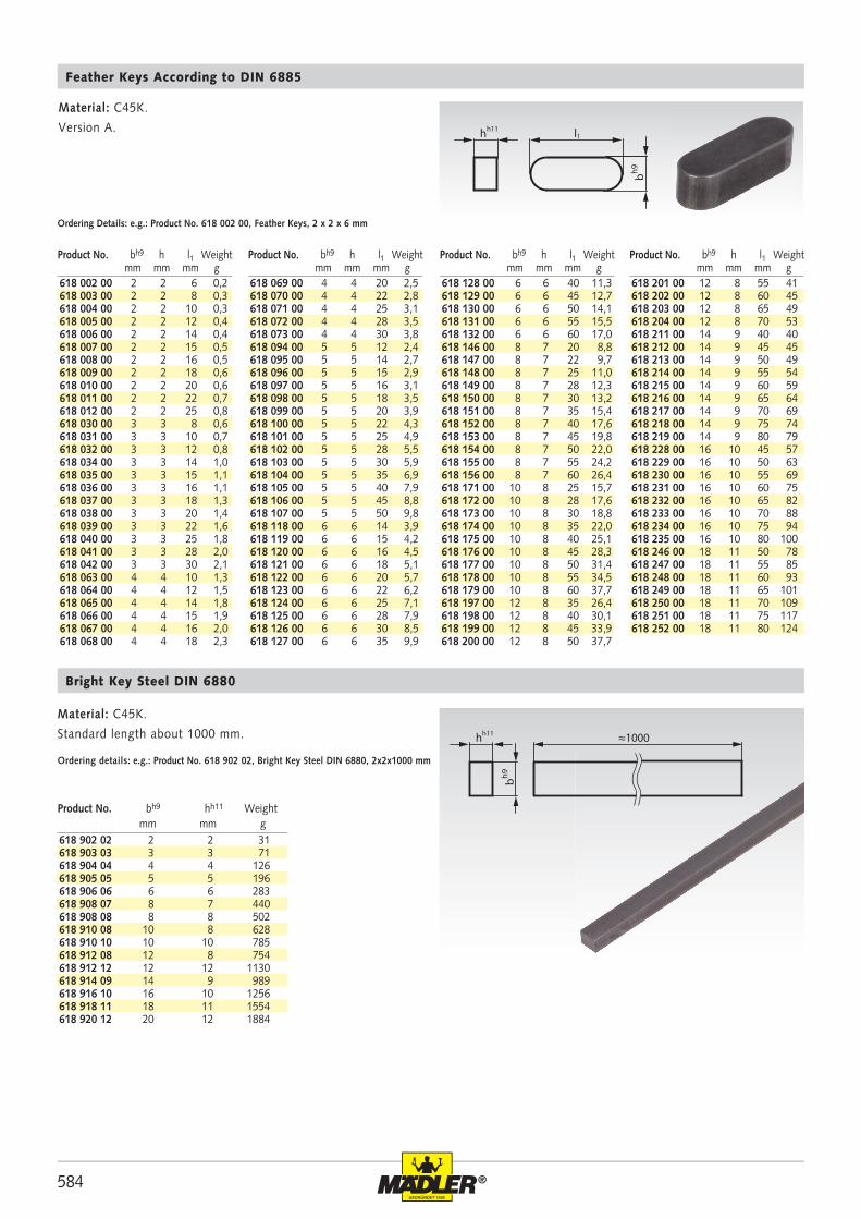
584 ®
hh11 l1
bh9
618 002 00 2 2 6 0,2618 003 00 2 2 8 0,3618 004 00 2 2 10 0,3618 005 00 2 2 12 0,4618 006 00 2 2 14 0,4618 007 00 2 2 15 0,5618 008 00 2 2 16 0,5618 009 00 2 2 18 0,6618 010 00 2 2 20 0,6618 011 00 2 2 22 0,7618 012 00 2 2 25 0,8618 030 00 3 3 8 0,6618 031 00 3 3 10 0,7618 032 00 3 3 12 0,8618 034 00 3 3 14 1,0618 035 00 3 3 15 1,1618 036 00 3 3 16 1,1618 037 00 3 3 18 1,3618 038 00 3 3 20 1,4618 039 00 3 3 22 1,6618 040 00 3 3 25 1,8618 041 00 3 3 28 2,0618 042 00 3 3 30 2,1618 063 00 4 4 10 1,3618 064 00 4 4 12 1,5618 065 00 4 4 14 1,8618 066 00 4 4 15 1,9618 067 00 4 4 16 2,0618 068 00 4 4 18 2,3
618 069 00 4 4 20 2,5618 070 00 4 4 22 2,8618 071 00 4 4 25 3,1618 072 00 4 4 28 3,5618 073 00 4 4 30 3,8618 094 00 5 5 12 2,4618 095 00 5 5 14 2,7618 096 00 5 5 15 2,9618 097 00 5 5 16 3,1618 098 00 5 5 18 3,5618 099 00 5 5 20 3,9618 100 00 5 5 22 4,3618 101 00 5 5 25 4,9618 102 00 5 5 28 5,5618 103 00 5 5 30 5,9618 104 00 5 5 35 6,9618 105 00 5 5 40 7,9618 106 00 5 5 45 8,8618 107 00 5 5 50 9,8618 118 00 6 6 14 3,9618 119 00 6 6 15 4,2618 120 00 6 6 16 4,5618 121 00 6 6 18 5,1618 122 00 6 6 20 5,7618 123 00 6 6 22 6,2618 124 00 6 6 25 7,1618 125 00 6 6 28 7,9618 126 00 6 6 30 8,5618 127 00 6 6 35 9,9
618 128 00 6 6 40 11,3618 129 00 6 6 45 12,7618 130 00 6 6 50 14,1618 131 00 6 6 55 15,5618 132 00 6 6 60 17,0618 146 00 8 7 20 8,8618 147 00 8 7 22 9,7618 148 00 8 7 25 11,0618 149 00 8 7 28 12,3618 150 00 8 7 30 13,2618 151 00 8 7 35 15,4618 152 00 8 7 40 17,6618 153 00 8 7 45 19,8618 154 00 8 7 50 22,0618 155 00 8 7 55 24,2618 156 00 8 7 60 26,4618 171 00 10 8 25 15,7618 172 00 10 8 28 17,6618 173 00 10 8 30 18,8618 174 00 10 8 35 22,0618 175 00 10 8 40 25,1618 176 00 10 8 45 28,3618 177 00 10 8 50 31,4618 178 00 10 8 55 34,5618 179 00 10 8 60 37,7618 197 00 12 8 35 26,4618 198 00 12 8 40 30,1618 199 00 12 8 45 33,9618 200 00 12 8 50 37,7
618 201 00 12 8 55 41618 202 00 12 8 60 45618 203 00 12 8 65 49618 204 00 12 8 70 53618 211 00 14 9 40 40618 212 00 14 9 45 45618 213 00 14 9 50 49618 214 00 14 9 55 54618 215 00 14 9 60 59618 216 00 14 9 65 64618 217 00 14 9 70 69618 218 00 14 9 75 74618 219 00 14 9 80 79618 228 00 16 10 45 57618 229 00 16 10 50 63618 230 00 16 10 55 69618 231 00 16 10 60 75618 232 00 16 10 65 82618 233 00 16 10 70 88618 234 00 16 10 75 94618 235 00 16 10 80 100618 246 00 18 11 50 78618 247 00 18 11 55 85618 248 00 18 11 60 93618 249 00 18 11 65 101618 250 00 18 11 70 109618 251 00 18 11 75 117618 252 00 18 11 80 124
hh11
bh9
≈1000
618 902 02 2 2 31618 903 03 3 3 71618 904 04 4 4 126618 905 05 5 5 196618 906 06 6 6 283618 908 07 8 7 440618 908 08 8 8 502618 910 08 10 8 628618 910 10 10 10 785618 912 08 12 8 754618 912 12 12 12 1130618 914 09 14 9 989618 916 10 16 10 1256618 918 11 18 11 1554618 920 12 20 12 1884
Feather Keys According to DIN 6885
Material: C45K.
Version A.
Ordering Details: e.g.: Product No. 618 002 00, Feather Keys, 2 x 2 x 6 mm
Bright Key Steel DIN 6880
Material: C45K.
Standard length about 1000 mm.
Ordering details: e.g.: Product No. 618 902 02, Bright Key Steel DIN 6880, 2x2x1000 mm
Product No. bh9 hh11 Weight mm mm g
Product No. bh9 h l1 Weight mm mm mm g
Product No. bh9 h l1 Weight mm mm mm g
Product No. bh9 h l1 Weight mm mm mm g
Product No. bh9 h l1 Weight mm mm mm g
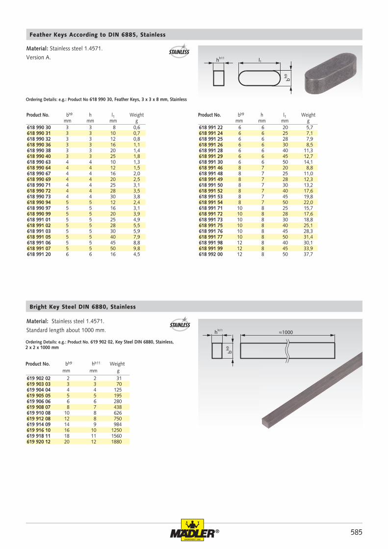
585®
hh11 l1
bh9
618 990 30 3 3 8 0,6618 990 31 3 3 10 0,7618 990 32 3 3 12 0,8618 990 36 3 3 16 1,1618 990 38 3 3 20 1,4618 990 40 3 3 25 1,8618 990 63 4 4 10 1,3618 990 64 4 4 12 1,5618 990 67 4 4 16 2,0618 990 69 4 4 20 2,5618 990 71 4 4 25 3,1618 990 72 4 4 28 3,5618 990 73 4 4 30 3,8618 990 94 5 5 12 2,4618 990 97 5 5 16 3,1618 990 99 5 5 20 3,9618 991 01 5 5 25 4,9618 991 02 5 5 28 5,5618 991 03 5 5 30 5,9618 991 05 5 5 40 7,9618 991 06 5 5 45 8,8618 991 07 5 5 50 9,8618 991 20 6 6 16 4,5
618 991 22 6 6 20 5,7618 991 24 6 6 25 7,1618 991 25 6 6 28 7,9618 991 26 6 6 30 8,5618 991 28 6 6 40 11,3618 991 29 6 6 45 12,7618 991 30 6 6 50 14,1618 991 46 8 7 20 8,8618 991 48 8 7 25 11,0618 991 49 8 7 28 12,3618 991 50 8 7 30 13,2618 991 52 8 7 40 17,6618 991 53 8 7 45 19,8618 991 54 8 7 50 22,0618 991 71 10 8 25 15,7618 991 72 10 8 28 17,6618 991 73 10 8 30 18,8618 991 75 10 8 40 25,1618 991 76 10 8 45 28,3618 991 77 10 8 50 31,4618 991 98 12 8 40 30,1618 991 99 12 8 45 33,9618 992 00 12 8 50 37,7
hh11
bh9
≈1000
619 902 02 2 2 31619 903 03 3 3 70619 904 04 4 4 125619 905 05 5 5 195619 906 06 6 6 280619 908 07 8 7 438619 910 08 10 8 626619 912 08 12 8 750619 914 09 14 9 984619 916 10 16 10 1250619 918 11 18 11 1560619 920 12 20 12 1880
Product No. bh9 hh11 Weight mm mm g
Material: Stainless steel 1.4571.
Standard length about 1000 mm.
Ordering Details: e.g.: Product No. 619 902 02, Key Steel DIN 6880, Stainless, 2 x 2 x 1000 mm
Material: Stainless steel 1.4571.
Version A.
Ordering Details: e.g.: Product No 618 990 30, Feather Keys, 3 x 3 x 8 mm, Stainless
Product No. bh9 h l1 Weight mm mm mm g
Feather Keys According to DIN 6885, Stainless
Bright Key Steel DIN 6880, Stainless
STAINLESS
STAINLESS
Product No. bh9 h l1 Weight mm mm mm g
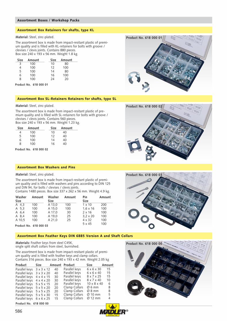
586 ®
3 100 4 100 5 100 6 100 8 100
10 80 12 100 14 80 16 100 24 20
4 100 5 100 6 100 8 100
10 40 12 40 14 40 16 40
1 x 10 2001,6 x 16 1002 x 16 1003,2 x 20 1004 x 32 1005 x 45 100
A 13,0 100 A 15,0 100 A 17,0 30 A 19,0 25 A 21,0 25
A 4,3 100A 5,3 100A 6,4 100A 8,4 100 A 10,5 100
Assortment Box Retainers for shafts, type KL
Product No. 618 000 01
Material: Steel, zinc-plated.
The assortment box is made from impact-resitant plastic of premi-um quality and is filled with KL-retainers for bolts with groove / clevises / clevis joints. Contains 880 pieces. Box size 240 x 193 x 56 mm. Weight 1.8 kg.
Assortment Box SL-Retainers Retainers for shafts, type SL
Product No. 618 000 02
Material: Steel, zinc-plated.
The assortment box is made from impact-resitant plastic of pre-mium quality and is filled with SL-retainers for bolts with groove / clevises / clevis joints. Contains 560 pieces. Box size 240 x 193 x 56 mm. Weight 1.23 kg.
Size Amount
Assortment Box Washers and Pins
Product No. 618 000 03
Material: Steel, zinc-plated.
The assortment box is made from impact-resitant plastic of premi-um quality and is filled with washers and pins according to DIN 125 and DIN 94, for bolts / clevises / clevis joints. Contains 1480 pieces. Box size 337 x 262 x 56 mm. Weight 4.9 kg.
Pin AmountSize
Washer AmountSize
Assortment Box Feather Keys DIN 6885 Version A and Shaft Collars
Product Size AmountParallel keys 3 x 3 x 12 40Parallel keys 3 x 3 x 20 40Parallel keys 4 x 4 x 15 30Parallel keys 4 x 4 x 20 30Parallel keys 5 x 5 x 15 20Parallel keys 5 x 5 x 20 20Parallel keys 5 x 5 x 25 20Parallel keys 5 x 5 x 30 15Parallel keys 6 x 6 x 25 15Product No. 618 000 00
Materials: Feather keys from steel C45K,single split shaft collars from steel, burnished.
The assortment box is made from impact-resitant plastic of premi-um quality and is filled with feather keys and clamp collars. Contains 316 pieces. Box size 240 x 193 x 42 mm. Weight 2.05 kg
Assortment Boxes / Workshop Packs
Size Amount
Size Amount Size Amount
Washer AmountSize
Product Size AmountParallel keys 6 x 6 x 30 15Parallel keys 6 x 6 x 40 15Parallel keys 8 x 7 x 25 15Parallel keys 8 x 7 x 40 10Parallel keys 10 x 8 x 40 6Clamp Collars Ø 6 mm 8Clamp Collars Ø 8 mm 8Clamp Collars Ø 10 mm 5 Clamp Collars Ø 12 mm 4
Product No. 618 000 01
Product No. 618 000 02
Product No. 618 000 03
Product No. 618 000 00
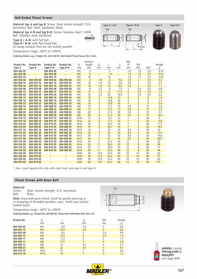
587®
654 604 06 M4 6,5 2,5 2 0,5654 604 10 M4 10,5 2,5 2 0,8654 605 08 M5 8,5 3 2,5 0,9654 605 12 M5 12,5 3 2,5 1,4654 606 11 M6 11,5 4 3 1,7654 606 17 M6 17,5 4 3 2,5654 608 12 M8 12 5,5 4 2,7654 608 22 M8 22 5,5 4 6,1654 610 14 M10 14 7 5 5,6654 610 18 M10 18 7 5 7,2
SW SW
654 503 05 - 654 903 05 - M3 5 - 5 - 1,5 1,5 2,5 0,15654 503 08 - 654 903 08 - M3 8 - 7,5 - 1,5 1,5 2,5 0,22654 503 10 - 654 903 10 - M3 10 - 10 - 1,5 1,5 2,5 0,33654 504 06 654 554 06 654 904 06 654 954 06 M4 6 1,8 6 5,6 2,5 2 3,5 0,4654 504 10 654 554 10 654 904 10 654 954 10 M4 10 1,8 10 9,6 2,5 2 3,5 0,7654 504 16 654 554 16 654 904 16 654 954 16 M4 16 1,8 16 15,6 2,5 2 3,5 1,1654 505 08 654 555 08 654 905 08 654 955 08 M5 8 2,2 8 7,5 3 2,5 4,5 0,8654 505 12 654 555 12 654 905 12 654 955 12 M5 12 2,2 12 11,5 3 2,5 4,5 1,3654 505 20 654 555 20 654 905 20 654 955 20 M5 20 2,2 20 19,5 3 2,5 4,5 2,3654 506 10 654 556 10 654 906 10 654 956 10 M6 10 3 10,8 10 4 3 9 1,5654 506 16 654 556 16 654 906 16 654 956 16 M6 16 3 16,8 16 4 3 9 2,4654 506 25 654 556 25 654 906 25 654 956 25 M6 25 3 25,8 25 4 3 9 3,9654 508 10 654 558 10 654 908 10 654 958 10 M8 10 5 11,2 10 5,5 4 15 2,6654 508 12 654 558 12 654 908 12 654 958 12 M8 12 5 13,2 12 5,5 4 15 3,2654 508 20 654 558 20 654 908 20 654 958 20 M8 20 5 21,2 20 5,5 4 15 5,7654 508 30 654 558 30 654 908 30 654 958 30 M8 30 5 31,2 30 5,5 4 15 8,9654 510 12 654 560 12 654 910 12 654 960 12 M10 12 6 13,7 12 7 5 20 5654 510 16 654 560 16 654 910 16 654 960 16 M10 16 6 17,7 16 7 5 20 6,8654 510 25 654 560 25 654 910 25 654 960 25 M10 25 6 26,7 25 7 5 20 11,2654 510 35 654 560 35 654 910 35 654 960 35 M10 35 6 36,7 35 7 5 20 16,2654 512 16 654 562 16 654 912 16 654 962 16 M12 16 7 18 16 8,5 6 30 10654 512 20 654 562 20 654 912 20 654 962 20 M12 20 7 22 20 8,5 6 30 12,4654 512 30 654 562 30 654 912 30 654 962 30 M12 30 7 32 30 8,5 6 30 19,6654 512 40 654 562 40 654 912 40 654 962 40 M12 40 7 42 40 8,5 6 30 28,5654 516 20 654 566 20 654 916 20 654 966 20 M16 20 11 23,3 20 12 8 60 22654 516 25 654 566 25 654 916 25 654 966 25 M16 25 11 28,3 25 12 8 60 28654 516 35 654 566 35 654 916 35 654 966 35 M16 35 11 38,3 35 12 8 60 41654 516 50 654 566 50 654 916 50 654 966 50 M16 50 11 53,3 50 12 8 60 48654 520 30 654 570 30 - - M20 30 13,5 34,2 30 15 10 90 52654 520 40 654 570 40 - - M20 40 13,5 44,2 40 15 10 90 72654 520 50 654 570 50 - - M20 50 13,5 54,2 50 15 10 90 93654 520 60 654 570 60 - - M20 60 13,5 64,2 60 15 10 90 115
Material typ A and typ B: Screw: Steel tensile strength 12.9, burnished. Ball: Steel, hardened, blank.
Material typ A-N and typ B-N: Screw: Stainless steel 1.4305. Ball: Stainless steel, hardened.
Type A / A-N: with full ball.Type B / B-N: with flat-faced ball, to clamp surfaces that are not exactly parallel.
Temperature range: -60ºC to +350ºC.
Ball-Ended Thrust Screws
Ordering Details: e.g.: Product No. 654 503 05, Ball-Ended Thrust Screw M3 x 5mm
* Max. Load Capacity kN, only with static load, only type A and type B.
Material:Screw: Steel, tensile strength 12.9, burnished.Bolt: Brass.
Note: Brass bolt press-fitted. Used for gentle pressing-in or clamping of threaded spindles, axles, shafts and surface treated parts.
Temperature range: -60ºC to +350ºC.
Thrust Screws with Brass Bolt
Ordering Details: e.g.: Product No. 654 604 06, Thrust Screw with Brass Bolt, M4 x 6.5
Product No. d1 l d2 SW Weight mm mm mm mm g
Type A / A-N Type B / B-N Type A Type B-N
Nominal BallProduct No. Product No. Product No. Product No. d1 length d3 l1 l2 Ø SW WeightType A Type B Type A-N Type B-N mm mm mm mm mm mm mm kN* g
STAINLESS
Loctite Thread Locking page 849.
Adhésifs Loctite (freinage des filetages)voir page 849.
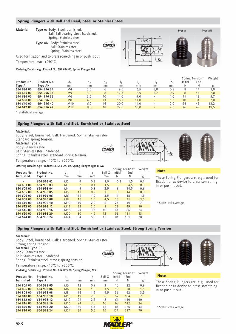
588 ®
- 654 996 02 M2 4 0,3 1,0 0,8 1,5 0,1654 603 00 654 996 03 M3 7 0,4 1,5 3 4,5 0,3654 604 00 654 996 04 M4 9 0,8 2,5 6 14,5 0,6654 605 00 654 996 05 M5 12 0,9 3 8 14 0,9654 606 00 654 996 06 M6 14 1,0 3,5 11 18 1,5654 608 00 654 996 08 M8 16 1,5 4,5 18 31 3,5654 610 00 654 996 10 M10 19 2,0 6 24 45 7654 612 00 654 996 12 M12 22 2,5 8 26 49 10654 616 00 654 996 16 M16 24 3,5 10 41 86 24654 620 00 654 996 20 M20 30 4,5 12 56 111 43654 624 00 654 996 24 M24 34 5,5 15 81 151 70
654 634 00 654 996 34 M4 2,5 6 9,5 6,5 5,0 0,8 8 14 1,0654 635 00 654 996 35 M5 3,0 8 12,5 8,5 6,7 0,9 8 14 2,0654 636 00 654 996 36 M6 3,5 10 14,0 9,0 - 1,0 11 18 3,7654 638 00 654 996 38 M8 4,5 13 16,5 11,0 - 1,5 18 31 7,0654 640 00 654 996 40 M10 6,0 16 20,0 14,0 - 2,0 24 45 13,2654 642 00 654 996 42 M12 8,0 18 22,0 15,0 - 2,5 26 49 19,5
654 805 00 654 998 05 M5 12 0,9 3 15 22 0,9654 806 00 654 998 06 M6 14 1,0 3,5 19 28 1,5654 808 00 654 998 08 M8 16 1,5 4,5 36 62 3,5654 810 00 654 998 10 M10 19 2,0 6 57 104 7654 812 00 654 998 12 M12 22 2,5 8 61 110 10654 816 00 654 998 16 M16 24 3,5 10 68 142 24654 820 00 654 998 20 M20 30 4,5 12 84 166 43654 824 00 654 998 24 M24 34 5,5 15 127 237 70
Spring Tension* WeightProduct No. Product No. d1 l s Ball Ø Initial Endburnished Type R mm mm mm mm N N g
Spring Plungers with Ball and Slot, Burnished or Stainless Steel
Material:Body: Steel, burnished. Ball: Hardened. Spring: Stainless steel.Standard spring tension. Material Type R:Body: Stainless steel.Ball: Stainless steel, hardened.Spring: Stainless steel, standard spring tension.
Temperature range: -40ºC to +250ºC.
* Statistical average.
These Spring Plungers are, e.g., used for fixation or as device to press something in or push it out.
Note
Ordering Details: e.g.: Product No. 654 634 00, Spring Plunger M4
* Statistical average.
Spring Plungers with Ball and Head, Steel or Stainless Steel
Material: Type A: Body: Steel, burnished. Ball: Ball bearing steel, hardened. Spring: Stainless steel.
Type AN: Body: Stainless steel. Ball: Stainless steel. Spring: Stainless steel.
Used for fixation and to press something in or push it out.
Temperature: max. +250°C.
Spring Tension* WeightProduct No. Product No. d1 d2 d3 l1 l2 l3 S Initial EndType A Type AN mm mm mm mm mm mm mm N N g
STAINLESS
STAINLESS
Type A Type AN
Spring Tension* WeightProduct No. Product No. d1 l s Ball Ø Initial Endburnished Type R mm mm mm mm N N g
Spring Plungers with Ball and Slot, Burnished or Stainless Steel, Strong Spring Tension
Material:Body: Steel, burnished. Ball: Hardened. Spring: Stainless steel.Strong spring tension. Material Type R:Body: Stainless steel.Ball: Stainless steel, hardened.Spring: Stainless steel, strong spring tension.
Temperature range: -40ºC to +250ºC.
* Statistical average.
These Spring Plungers are, e.g., used for fixation or as device to press something in or push it out.
Note
STAINLESS
Ordering Details: e.g.: Product No. 654 996 02, Spring Plunger Type R, M2
Ordering Details: e.g.: Product No. 654 805 00, Spring Plunger, M5
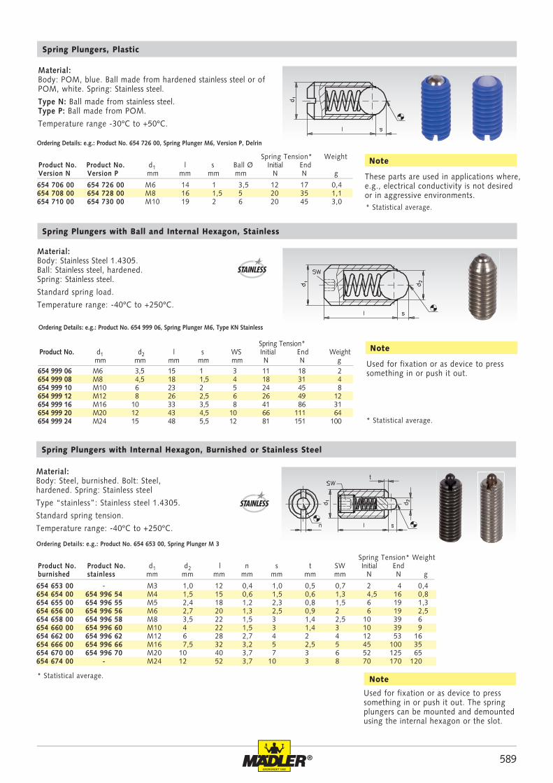
589®
654 706 00 654 726 00 M6 14 1 3,5 12 17 0,4654 708 00 654 728 00 M8 16 1,5 5 20 35 1,1654 710 00 654 730 00 M10 19 2 6 20 45 3,0
654 999 06 M6 3,5 15 1 3 11 18 2654 999 08 M8 4,5 18 1,5 4 18 31 4654 999 10 M10 6 23 2 5 24 45 8654 999 12 M12 8 26 2,5 6 26 49 12654 999 16 M16 10 33 3,5 8 41 86 31654 999 20 M20 12 43 4,5 10 66 111 64654 999 24 M24 15 48 5,5 12 81 151 100
654 653 00 - M3 1,0 12 0,4 1,0 0,5 0,7 2 4 0,4 654 654 00 654 996 54 M4 1,5 15 0,6 1,5 0,6 1,3 4,5 16 0,8 654 655 00 654 996 55 M5 2,4 18 1,2 2,3 0,8 1,5 6 19 1,3 654 656 00 654 996 56 M6 2,7 20 1,3 2,5 0,9 2 6 19 2,5 654 658 00 654 996 58 M8 3,5 22 1,5 3 1,4 2,5 10 39 6 654 660 00 654 996 60 M10 4 22 1,5 3 1,4 3 10 39 9 654 662 00 654 996 62 M12 6 28 2,7 4 2 4 12 53 16 654 666 00 654 996 66 M16 7,5 32 3,2 5 2,5 5 45 100 35 654 670 00 654 996 70 M20 10 40 3,7 7 3 6 52 125 65 654 674 00 - M24 12 52 3,7 10 3 8 70 170 120
Spring Tension* WeightProduct No. Product No. d1 l s Ball Ø Initial EndVersion N Version P mm mm mm mm N N g
Spring Plungers, Plastic
Material: Body: POM, blue. Ball made from hardened stainless steel or of POM, white. Spring: Stainless steel.
Type N: Ball made from stainless steel.Type P: Ball made from POM.
Temperature range -30ºC to +50ºC.
Ordering Details: e.g.: Product No. 654 726 00, Spring Plunger M6, Version P, Delrin
These parts are used in applications where, e.g., electrical conductivity is not desired or in aggressive environments.
Note
* Statistical average.
Material:Body: Stainless Steel 1.4305.Ball: Stainless steel, hardened.Spring: Stainless steel.
Standard spring load.
Temperature range: -40ºC to +250ºC.
Spring Plungers with Ball and Internal Hexagon, Stainless
Ordering Details: e.g.: Product No. 654 999 06, Spring Plunger M6, Type KN Stainless
Spring Tension*Product No. d1 d2 l s WS Initial End Weight mm mm mm mm mm N N g Used for fixation or as device to press
something in or push it out.
Note
* Statistical average.
Spring Tension* WeightProduct No. Product No. d1 d2 l n s t SW Initial End
burnished stainless mm mm mm mm mm mm mm N N g
Spring Plungers with Internal Hexagon, Burnished or Stainless Steel
Material:Body: Steel, burnished. Bolt: Steel, hardened. Spring: Stainless steel
Type “stainless”: Stainless steel 1.4305.
Standard spring tension.
Temperature range: -40ºC to +250ºC.
Ordering Details: e.g.: Product No. 654 653 00, Spring Plunger M 3
* Statistical average.
Used for fixation or as device to press something in or push it out. The spring plungers can be mounted and demounted using the internal hexagon or the slot.
Note
STAINLESS
STAINLESS
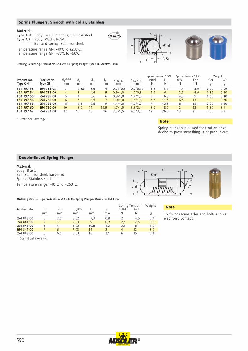
590 ®
654 997 53 654 784 03 3 2,38 3,5 4 0,75/0,6 0,7/0,55 1,8 3,5 1,7 3,5 0,20 0,09654 997 54 654 784 00 4 3 4,6 5 0,9/1,0 1,0/0,8 2,5 6 2,5 6,5 0,35 0,20654 997 55 654 785 00 5 4 5,6 6 0,9/1,0 1,4/1,0 3 6,5 4,5 9 0,60 0,40654 997 56 654 786 00 6 5 6,5 7 1,0/1,0 1,8/1,6 5,5 11,5 6,5 13 1,00 0,70654 997 58 654 788 00 8 6,5 8,5 9 1,1/1,0 1,9/1,9 7 12,5 8 18 2,20 1,50654 997 60 654 790 00 10 8,5 11 13,5 1,7/1,5 3,3/2,4 8,5 18,5 12 23 5,30 3,1654 997 62 654 792 00 12 10 13 16 2,3/1,5 4,0/3,3 12 26,5 13 25 7,80 5,8
654 843 00 3 2,5 3,02 7,3 0,8 2 4,5 0,4654 844 00 4 3 4,03 9 0,9 2,5 7,5 0,6654 845 00 5 4 5,03 10,8 1,2 3,5 8 1,2654 847 00 7 6 7,03 14 2 4 12 3,0654 848 00 8 6,5 8,03 18 2,1 6 15 5,1
Spring Plungers, Smooth with Collar, Stainless
Material:Type GN: Body, ball and spring stainless steel.Type GP: Body: Plastic POM. Ball and spring: Stainless steel.
Temperature range GN: -40ºC to +250ºC.Temperature range GP: -30ºC to +50ºC.
Ordering Details: e.g.: Product No. 654 997 53, Spring Plunger, Type GN, Stainless, 3mm
Note* Statistical average.
Double-Ended Spring Plunger
Material:Body: Brass.Ball: Stainless steel, hardened. Spring: Stainless steel.
Temperature range: -40ºC to +250ºC.
Ordering Details: e.g.: Product No. 654 843 00, Spring Plunger, Double-Ended 3 mm
* Statistical average.
To fix or secure axles and bolts and as electronic contact.
Note
Spring plungers are used for fixation or as device to press something in or push it out.
Knurl
Spring Tension* GN Spring Tension* GP WeightProduct No. Product No. d1
+0,08 d2 d3 l1 l2 GN / GP s GN / GP Initial F2 Initial End GN GPType GN Type GP mm mm mm mm mm mm N N N N g g
Spring Tension* WeightProduct No. d1 d2 d3
+0,5 l1 s Initial End mm mm mm mm mm N N g
STAINLESS
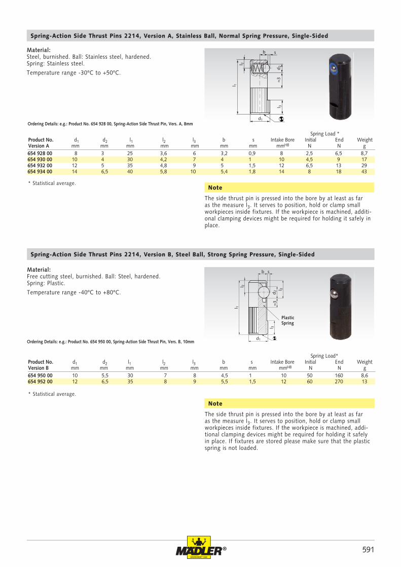
591®
654 928 00 8 3 25 3,6 6 3,2 0,9 8 2,5 6,5 8,7654 930 00 10 4 30 4,2 7 4 1 10 4,5 9 17654 932 00 12 5 35 4,8 9 5 1,5 12 6,5 13 29654 934 00 14 6,5 40 5,8 10 5,4 1,8 14 8 18 43
654 950 00 10 5,5 30 7 8 4,5 1 10 50 160 8,6654 952 00 12 6,5 35 8 9 5,5 1,5 12 60 270 13
b s
d 2≈3
l 2
l 1
d1
l 3
b
d1
d 2l 3
≈3l 2
l 1
s
l 2
Spring-Action Side Thrust Pins 2214, Version A, Stainless Ball, Normal Spring Pressure, Single-Sided
Ordering Details: e.g.: Product No. 654 928 00, Spring-Action Side Thrust Pin, Vers. A, 8mm
Spring Load *Product No. d1 d2 l1 l2 l3 b s Intake Bore Initial End WeightVersion A mm mm mm mm mm mm mm mmH8 N N g
Material:Steel, burnished. Ball: Stainless steel, hardened. Spring: Stainless steel.
Temperature range -30ºC to +50ºC.
The side thrust pin is pressed into the bore by at least as far as the measure l3. It serves to position, hold or clamp small workpieces inside fixtures. If the workpiece is machined, addi-tional clamping devices might be required for holding it safely in place. If fixtures are stored please make sure that the plastic spring is not loaded.
Spring Load*Product No. d1 d2 l1 l2 l3 b s Intake Bore Initial End WeightVersion B mm mm mm mm mm mm mm mmH8 N N g
* Statistical average.
Note
PlasticSpring
Material:Free cutting steel, burnished. Ball: Steel, hardened. Spring: Plastic.
Temperature range -40ºC to +80ºC.
Spring-Action Side Thrust Pins 2214, Version B, Steel Ball, Strong Spring Pressure, Single-Sided
Ordering Details: e.g.: Product No. 654 950 00, Spring-Action Side Thrust Pin, Vers. B, 10mm
* Statistical average.
The side thrust pin is pressed into the bore by at least as far as the measure l3. It serves to position, hold or clamp small workpieces inside fixtures. If the workpiece is machined, additi-onal clamping devices might be required for holding it safely in place.
Note
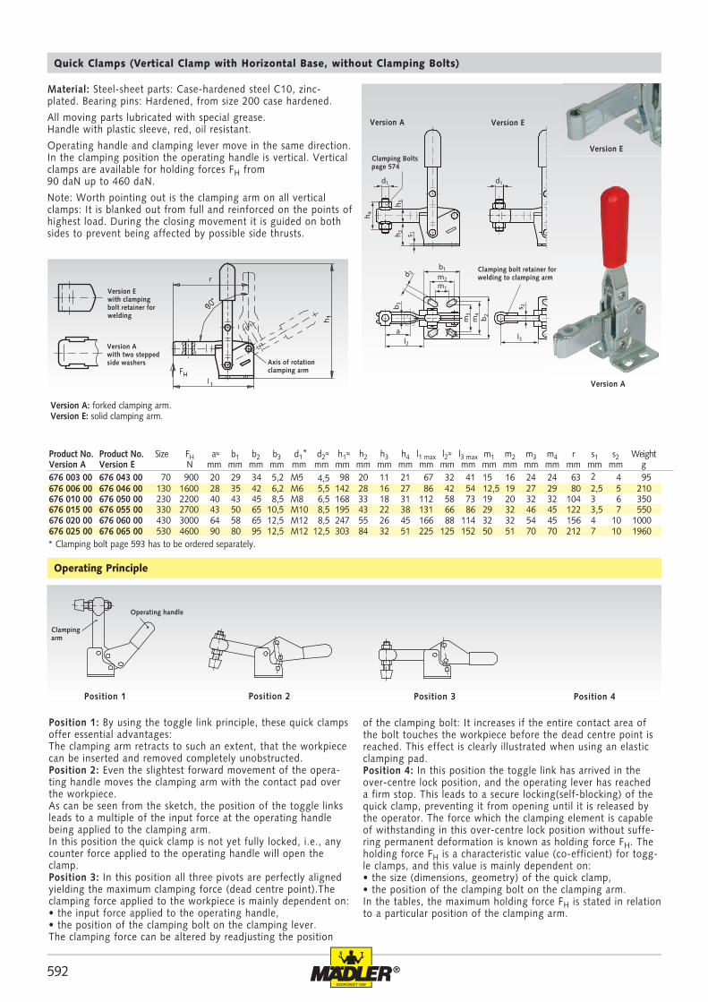
592 ®
h 4
h 3h 2
m3
m4
b 2
s 2b 3
s 1
d1
m1
a
m2
l2l3
b1
d 2
d1
676 003 00 676 043 00 70 900 20 29 34 5,2 M5 4,5 98 20 11 21 67 32 41 15 16 24 24 63 2 4 95676 006 00 676 046 00 130 1600 28 35 42 6,2 M6 5,5 142 28 16 27 86 42 54 12,5 19 27 29 80 2,5 5 210676 010 00 676 050 00 230 2200 40 43 45 8,5 M8 6,5 168 33 18 31 112 58 73 19 20 32 32 104 3 6 350676 015 00 676 055 00 330 2700 43 50 65 10,5 M10 8,5 195 43 22 38 131 66 86 29 32 46 45 122 3,5 7 550676 020 00 676 060 00 430 3000 64 58 65 12,5 M12 8,5 247 55 26 45 166 88 114 32 32 54 45 156 4 10 1000676 025 00 676 065 00 530 4600 90 80 95 12,5 M12 12,5 303 84 32 51 225 125 152 50 51 70 70 212 7 10 1960
Material: Steel-sheet parts: Case-hardened steel C10, zinc-plated. Bearing pins: Hardened, from size 200 case hardened.
All moving parts lubricated with special grease.Handle with plastic sleeve, red, oil resistant.
Operating handle and clamping lever move in the same direction. In the clamping position the operating handle is vertical. Vertical clamps are available for holding forces FH from90 daN up to 460 daN.
Note: Worth pointing out is the clamping arm on all vertical clamps: It is blanked out from full and reinforced on the points of highest load. During the closing movement it is guided on both sides to prevent being affected by possible side thrusts.
Quick Clamps (Vertical Clamp with Horizontal Base, without Clamping Bolts)
Position 1: By using the toggle link principle, these quick clamps offer essential advantages: The clamping arm retracts to such an extent, that the workpiece can be inserted and removed completely unobstructed. Position 2: Even the slightest forward movement of the opera-ting handle moves the clamping arm with the contact pad over the workpiece. As can be seen from the sketch, the position of the toggle links leads to a multiple of the input force at the operating handle being applied to the clamping arm. In this position the quick clamp is not yet fully locked, i.e., any counter force applied to the operating handle will open the clamp.Position 3: In this position all three pivots are perfectly aligned yielding the maximum clamping force (dead centre point).The clamping force applied to the workpiece is mainly dependent on:• the input force applied to the operating handle, • the position of the clamping bolt on the clamping lever. The clamping force can be altered by readjusting the position
Operating Principle
of the clamping bolt: It increases if the entire contact area of the bolt touches the workpiece before the dead centre point is reached. This effect is clearly illustrated when using an elastic clamping pad.Position 4: In this position the toggle link has arrived in the over-centre lock position, and the operating lever has reached a firm stop. This leads to a secure locking(self-blocking) of the quick clamp, preventing it from opening until it is released by the operator. The force which the clamping element is capable of withstanding in this over-centre lock position without suffe-ring permanent deformation is known as holding force FH. The holding force FH is a characteristic value (co-efficient) for togg-le clamps, and this value is mainly dependent on: • the size (dimensions, geometry) of the quick clamp, • the position of the clamping bolt on the clamping arm. In the tables, the maximum holding force FH is stated in relation to a particular position of the clamping arm.
Position 1 Position 2 Position 3 Position 4
* Clamping bolt page 593 has to be ordered separately.
Version A: forked clamping arm.Version E: solid clamping arm.
Version Ewith clamping bolt retainer for welding
Version Awith two stepped side washers Axis of rotation
clamping arm
Operating handle
Clamping arm
Clamping bolt retainer for welding to clamping arm
Clamping Bolts page 574
Version A Version E
Version E
Version A
Product No. Product No. Size FH a≈ b1 b2 b3 d1* d2≈ h1≈ h2 h3 h4 l1 max l2≈ l3 max m1 m2 m3 m4 r s1 s2 WeightVersion A Version E N mm mm mm mm mm mm mm mm mm mm mm mm mm mm mm mm mm mm mm mm g
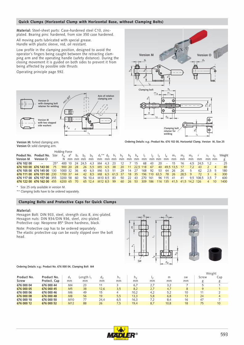
593®
676 000 04 676 000 44 M4 23 11 3 6,7 2,7 3,2 7 5 1676 000 05 676 000 45 M5 38 12,6 3,5 8,2 2,7 4,7 8 9 1676 000 06 676 000 46 M6 49 15 4 10,2 4,2 5,2 10 11 2676 000 08 676 000 48 M8 56 19 5,5 13,3 5,8 6,8 13 24 4676 000 10 676 000 50 M10 77 24,4 6,5 16,3 7,2 8,4 16 47 7676 000 12 676 000 52 M12 88 26 7,5 19,4 8,7 10,8 18 75 10
676 102 00 - 25* 400 10 24 24,5 4,3 M4 4,3 23 12 7 15 68 43 20 - 15 16 4,5 24,5 1,2 - 25676 103 00 676 143 00 75 900 20 28 26 5,5 M5 4,5 38 20 11 22,5 118 67 40 49,5 13,5 17 7,2 43 2 4 80676 105 00 676 145 00 130 1000 32 36 40 6,5 M6 5,5 51 29 14 27 168 92 53 64 26 26 5 62 2,5 5 180676 111 00 676 151 00 230 1700 37 44 42 8,5 M8 6,5 61,5 37 18 35 196 110 63,5 78 26 28,5 9 72 3 6 300676 117 00 676 157 00 355 3200 58 60 56 10,4 M10 8,5 83 50 22 43 270 161 96 115 41 41 9,5 108,5 3,5 7 600676 122 00 676 162 00 455 6200 65 70 65 12,4 M12 8,5 99 60 26 53 309 186 116 135 41,5 41,5 14,2 126 4 10 1400
WeightProduct No. Product No. d1 Length l1 d2 h1 h2 l2 m sw Screw CapScrew Protect. Cap mm mm mm mm mm mm mm mm g g
* Size 25 only available in version M. ** Clamping bolts have to be ordered separately.
Material: Steel-sheet parts: Case-hardened steel C10, zinc-plated. Bearing pins: hardened, from size 350 case hardened.
All moving parts lubricated with special grease.Handle with plastic sleeve, red, oil resistant.
Low profile in the clamping position, designed to avoid the operator’s fingers being caught between the retracting clam-ping arm and the operating handle (safety distance). During the closing movement it is guided on both sides to prevent it from being affected by possible side thrusts
Operating principle page 592.
Quick Clamps (Horizontal Clamp with Horizontal Base, without Clamping Bolts)
Ordering Details: e.g.: Product No. 676 102 00, Horizontal Clamp, Version M, Size 25
Holding Force Product No. Product No. Size FH a² b1 b2 b3 d1** d2 h1 h2 h3 h4 l1 l2 l3 l4 m1 m2 m3 r s1 s2 WeightVersion M Version O N mm mm mm mm mm mm mm mm mm mm mm mm mm mm mm mm mm mm mm mm g
Material:Hexagon Bolt: DIN 933, steel, strength class 8, zinc-plated.Hexagon nuts: DIN 934/DIN 936, steel, zinc-plated.Protective cap: Neoprene 85º Shore hardness, black.
Note: Protective cap has to be ordered separately.The elastic protective cap can be easily slipped over the bolt head.
Clamping Bolts and Protective Caps for Quick Clamps
Ordering Details: e.g.: Product No. 676 000 04, Clamping Bolt M4
Version M: forked clamping arm. Version O: solid clamping arm.
Version Owith clamping bolt retainer for welding
Version Mwith two stepped side washers
Axis of rotationclamping arm
Clamping bolt retainer for welding
Clamping bolt
Version M Version O
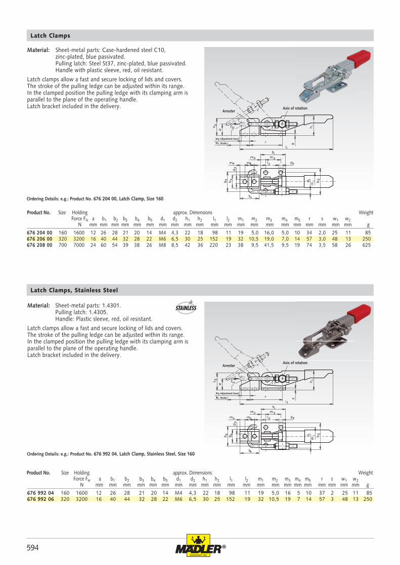
594 ®
676 992 04 160 1600 12 26 28 21 20 14 M4 4,3 22 18 98 11 19 5,0 16 5 10 37 2 25 11 85676 992 06 320 3200 16 40 44 32 28 22 M6 6,5 30 25 152 19 32 10,5 19 7 14 57 3 48 13 250
676 204 00 160 1600 12 26 28 21 20 14 M4 4,3 22 18 98 11 19 5,0 16,0 5,0 10 34 2,0 25 11 85676 206 00 320 3200 16 40 44 32 28 22 M6 6,5 30 25 152 19 32 10,5 19,0 7,0 14 57 3,0 48 13 250676 208 00 700 7000 24 60 54 39 38 26 M8 8,5 42 36 220 23 38 9,5 41,5 9,5 19 74 3,5 58 26 625
Arrester
Adjustment travel
Stroke
Axis of rotation
Latch Clamps, Stainless Steel
Material: Sheet-metal parts: 1.4301. Pulling latch: 1.4305. Handle: Plastic sleeve, red, oil resistant.
Latch clamps allow a fast and secure locking of lids and covers. The stroke of the pulling ledge can be adjusted within its range. In the clamped position the pulling ledge with its clamping arm is parallel to the plane of the operating handle. Latch bracket included in the delivery.
Ordering Details: e.g.: Product No. 676 992 04, Latch Clamp, Stainless Steel, Size 160
Product No. Size Holding approx. Dimensions Weight Force FH a b1 b2 b3 b4 b5 d1 d2 h1 h2 l1 l2 m1 m2 m3 m4 m5 r s w1 w2 N mm mm mm mm mm mm mm mm mm mm mm mm mm mm mm mm mm mm mm mm mm g
Latch Clamps
Material: Sheet-metal parts: Case-hardened steel C10, zinc-plated, blue passivated. Pulling latch: Steel St37, zinc-plated, blue passivated. Handle with plastic sleeve, red, oil resistant.
Latch clamps allow a fast and secure locking of lids and covers. The stroke of the pulling ledge can be adjusted within its range. In the clamped position the pulling ledge with its clamping arm is parallel to the plane of the operating handle. Latch bracket included in the delivery.
Ordering Details: e.g.: Product No. 676 204 00, Latch Clamp, Size 160
Product No. Size Holding approx. Dimensions Weight Force FH a b1 b2 b3 b4 b5 d1 d2 h1 h2 l1 l2 m1 m2 m3 m4 m5 r s w1 w2 N mm mm mm mm mm mm mm mm mm mm mm mm mm mm mm mm mm mm mm mm mm g
STAINLESS
Arrester
Adjustment travel
Stroke
Axis of rotation
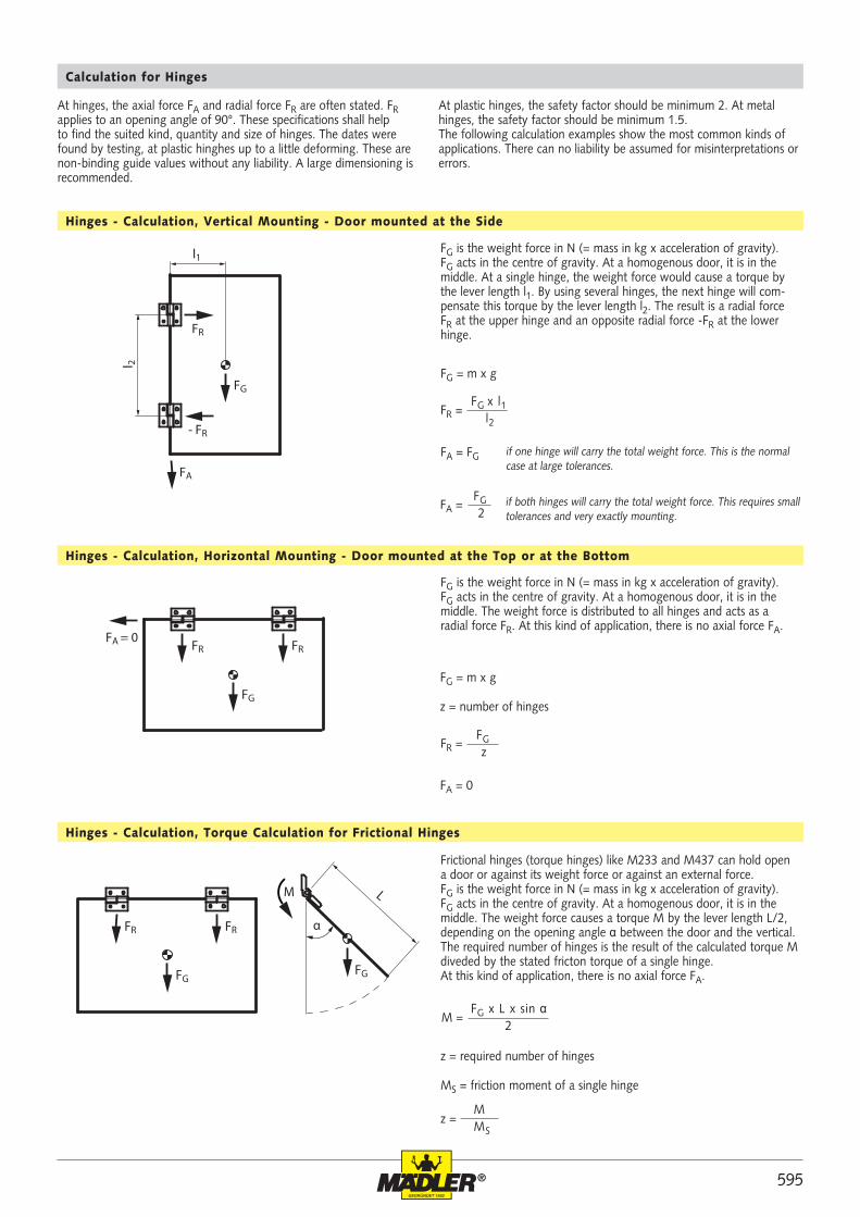
595®
FG
l1
l 2
FR
FA
- FR
FG
FRFA = 0
FR
FG
L
FRFR α
M
FG
FG = m x g
FG
zFR =
FA = 0
FG x L x sin α 2
M =
z = M MS
FG x l1 l2
FR =
FG = m x g
FA = FG
FG 2
FA =
Calculation for Hinges
Hinges - Calculation, Vertical Mounting - Door mounted at the Side
Hinges - Calculation, Horizontal Mounting - Door mounted at the Top or at the Bottom
Hinges - Calculation, Torque Calculation for Frictional Hinges
FG is the weight force in N (= mass in kg x acceleration of gravity). FG acts in the centre of gravity. At a homogenous door, it is in the middle. At a single hinge, the weight force would cause a torque by the lever length l1. By using several hinges, the next hinge will com-pensate this torque by the lever length l2. The result is a radial force FR at the upper hinge and an opposite radial force -FR at the lower hinge.
if one hinge will carry the total weight force. This is the normal case at large tolerances.
if both hinges will carry the total weight force. This requires small tolerances and very exactly mounting.
FG is the weight force in N (= mass in kg x acceleration of gravity). FG acts in the centre of gravity. At a homogenous door, it is in the middle. The weight force is distributed to all hinges and acts as a radial force FR. At this kind of application, there is no axial force FA.
z = number of hinges
Frictional hinges (torque hinges) like M233 and M437 can hold open a door or against its weight force or against an external force. FG is the weight force in N (= mass in kg x acceleration of gravity). FG acts in the centre of gravity. At a homogenous door, it is in the middle. The weight force causes a torque M by the lever length L/2, depending on the opening angle α between the door and the vertical. The required number of hinges is the result of the calculated torque M diveded by the stated fricton torque of a single hinge. At this kind of application, there is no axial force FA.
z = required number of hinges
MS = friction moment of a single hinge
At hinges, the axial force FA and radial force FR are often stated. FR applies to an opening angle of 90°. These specifications shall help to find the suited kind, quantity and size of hinges. The dates were found by testing, at plastic hinghes up to a little deforming. These are non-binding guide values without any liability. A large dimensioning is recommended.
At plastic hinges, the safety factor should be minimum 2. At metal hinges, the safety factor should be minimum 1.5. The following calculation examples show the most common kinds of applications. There can no liability be assumed for misinterpretations or errors.
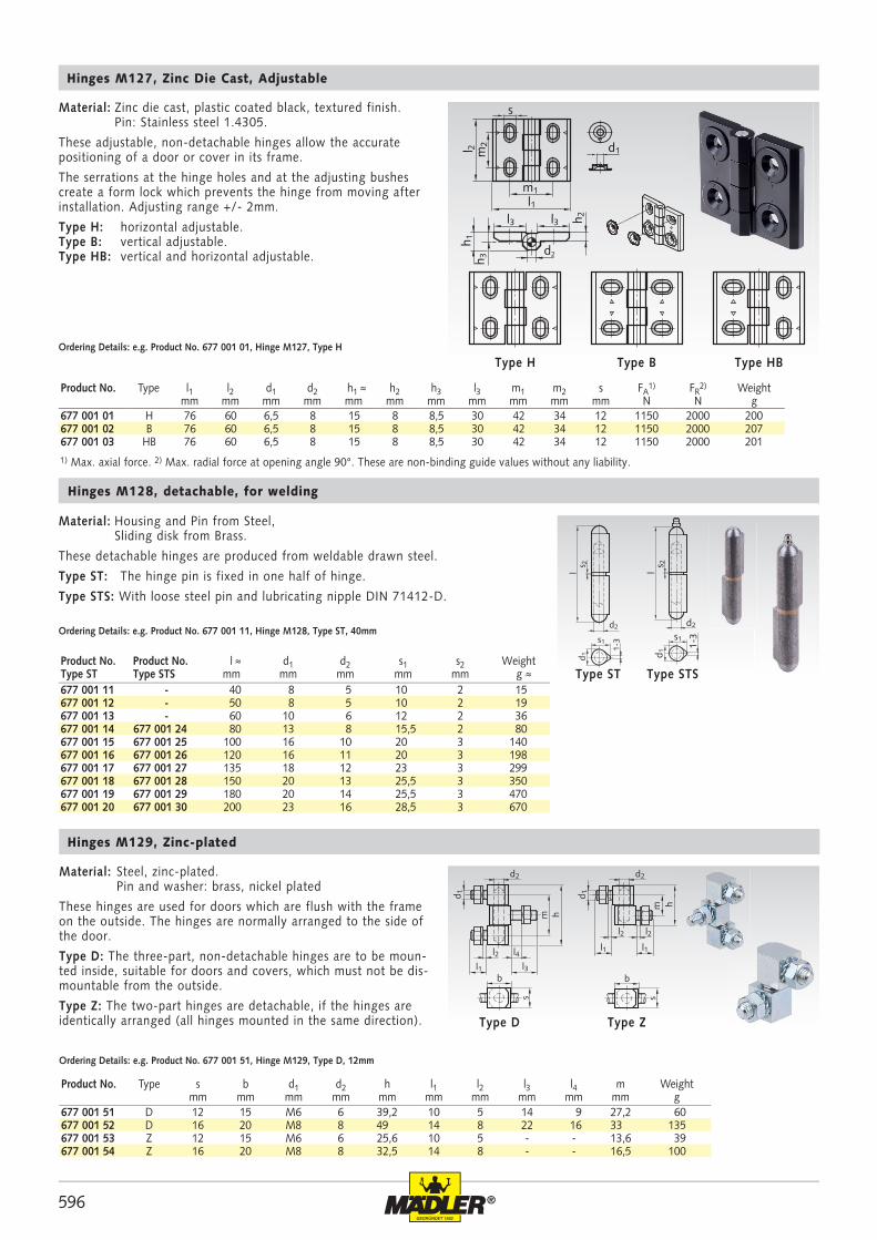
596 ®
677 001 01 H 76 60 6,5 8 15 8 8,5 30 42 34 12 1150 2000 200677 001 02 B 76 60 6,5 8 15 8 8,5 30 42 34 12 1150 2000 207677 001 03 HB 76 60 6,5 8 15 8 8,5 30 42 34 12 1150 2000 201
l
1-3
d2
s1
d 1s 2
677 001 11 - 40 8 5 10 2 15677 001 12 - 50 8 5 10 2 19677 001 13 - 60 10 6 12 2 36677 001 14 677 001 24 80 13 8 15,5 2 80677 001 15 677 001 25 100 16 10 20 3 140677 001 16 677 001 26 120 16 11 20 3 198677 001 17 677 001 27 135 18 12 23 3 299677 001 18 677 001 28 150 20 13 25,5 3 350677 001 19 677 001 29 180 20 14 25,5 3 470677 001 20 677 001 30 200 23 16 28,5 3 670
l
1-3
d2
s1
d 1s 2
m
d2
d 1
l1
l2 l4
h
l3b
s
l1 l1
l2 l2
d2
m h
b
d 1
s
677 001 51 D 12 15 M6 6 39,2 10 5 14 9 27,2 60677 001 52 D 16 20 M8 8 49 14 8 22 16 33 135677 001 53 Z 12 15 M6 6 25,6 10 5 - - 13,6 39677 001 54 Z 16 20 M8 8 32,5 14 8 - - 16,5 100
s
l 2 m2
m1l1
d1
h 2l3l3
h 3h 1
d2
Hinges M127, Zinc Die Cast, Adjustable
Ordering Details: e.g. Product No. 677 001 01, Hinge M127, Type H
Product No. Type l1 l2 d1 d2 h1 ≈ h2 h3 l3 m1 m2 s FA1) FR
2) Weightmm mm mm mm mm mm mm mm mm mm mm N N g
Type B Type HBType H
Material: Zinc die cast, plastic coated black, textured finish. Pin: Stainless steel 1.4305.
These adjustable, non-detachable hinges allow the accurate positioning of a door or cover in its frame.
The serrations at the hinge holes and at the adjusting bushes create a form lock which prevents the hinge from moving after installation. Adjusting range +/- 2mm.
Type H: horizontal adjustable.Type B: vertical adjustable.Type HB: vertical and horizontal adjustable.
Hinges M128, detachable, for welding
Material: Housing and Pin from Steel, Sliding disk from Brass.
These detachable hinges are produced from weldable drawn steel.
Type ST: The hinge pin is fixed in one half of hinge.
Type STS: With loose steel pin and lubricating nipple DIN 71412-D.
Ordering Details: e.g. Product No. 677 001 11, Hinge M128, Type ST, 40mm
Product No. Product No. l ≈ d1 d2 s1 s2 WeightType ST Type STS mm mm mm mm mm g ≈ Type STSType ST
Hinges M129, Zinc-plated
Material: Steel, zinc-plated. Pin and washer: brass, nickel plated
These hinges are used for doors which are flush with the frameon the outside. The hinges are normally arranged to the side of the door.
Type D: The three-part, non-detachable hinges are to be moun-ted inside, suitable for doors and covers, which must not be dis-mountable from the outside.
Type Z: The two-part hinges are detachable, if the hinges are identically arranged (all hinges mounted in the same direction).
Ordering Details: e.g. Product No. 677 001 51, Hinge M129, Type D, 12mm
Product No. Type s b d1 d2 h l1 l2 l3 l4 m Weightmm mm mm mm mm mm mm mm mm mm g
Type ZType D
1) Max. axial force. 2) Max. radial force at opening angle 90°. These are non-binding guide values without any liability.
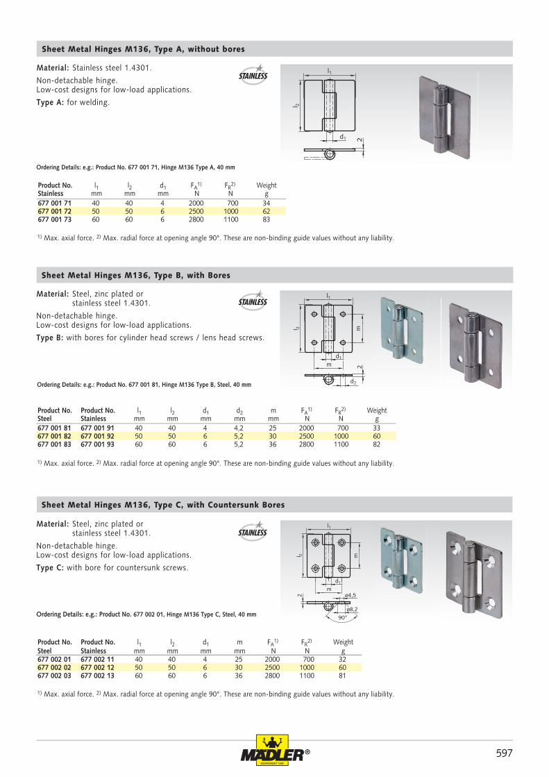
597®
677 001 71 40 40 4 2000 700 34677 001 72 50 50 6 2500 1000 62677 001 73 60 60 6 2800 1100 83
d1
l 2
2
l1
2
l 2
d1m
m
d2
l1
677 001 81 677 001 91 40 40 4 4,2 25 2000 700 33677 001 82 677 001 92 50 50 6 5,2 30 2500 1000 60677 001 83 677 001 93 60 60 6 5,2 36 2800 1100 82
90ø8,2
2 ø4,5
m
d1
m
l 2
l1
677 002 01 677 002 11 40 40 4 25 2000 700 32677 002 02 677 002 12 50 50 6 30 2500 1000 60677 002 03 677 002 13 60 60 6 36 2800 1100 81
Ordering Details: e.g.: Product No. 677 001 81, Hinge M136 Type B, Steel, 40 mm
Ordering Details: e.g.: Product No. 677 002 01, Hinge M136 Type C, Steel, 40 mm
Ordering Details: e.g.: Product No. 677 001 71, Hinge M136 Type A, 40 mm
Product No. l1 l2 d1 FA1) FR
2) WeightStainless mm mm mm N N g
STAINLESS
Sheet Metal Hinges M136, Type A, without bores
Material: Stainless steel 1.4301.
Non-detachable hinge.Low-cost designs for low-load applications.
Type A: for welding.
Sheet Metal Hinges M136, Type B, with Bores
Sheet Metal Hinges M136, Type C, with Countersunk Bores
Material: Steel, zinc plated or stainless steel 1.4301.
Non-detachable hinge.Low-cost designs for low-load applications.
Type B: with bores for cylinder head screws / lens head screws.
Material: Steel, zinc plated or stainless steel 1.4301.
Non-detachable hinge.Low-cost designs for low-load applications.
Type C: with bore for countersunk screws.
STAINLESS
STAINLESS
Product No. Product No. l1 l2 d1 m FA1) FR
2) WeightSteel Stainless mm mm mm mm N N g
Product No. Product No. l1 l2 d1 d2 m FA1) FR
2) WeightSteel Stainless mm mm mm mm mm N N g
1) Max. axial force. 2) Max. radial force at opening angle 90°. These are non-binding guide values without any liability.
1) Max. axial force. 2) Max. radial force at opening angle 90°. These are non-binding guide values without any liability.
1) Max. axial force. 2) Max. radial force at opening angle 90°. These are non-binding guide values without any liability.
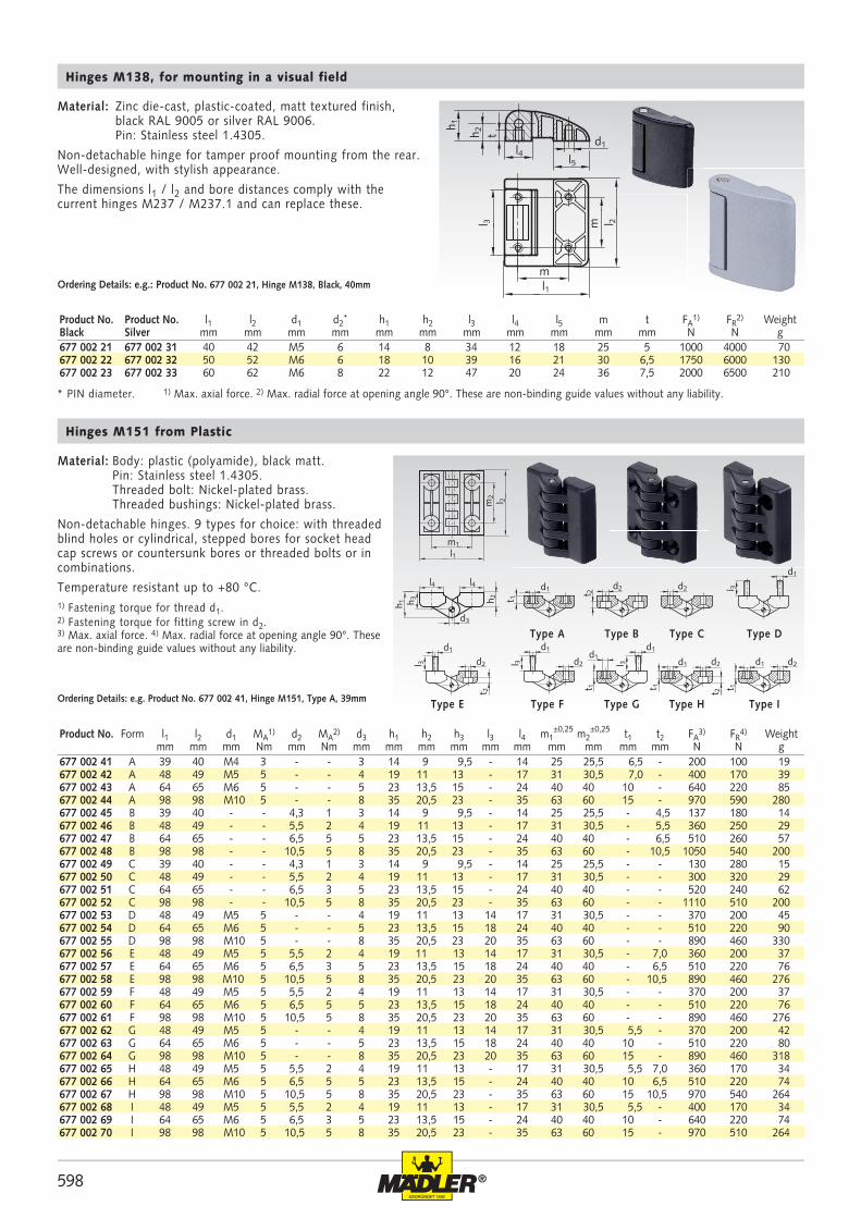
598 ®
677 002 21 677 002 31 40 42 M5 6 14 8 34 12 18 25 5 1000 4000 70677 002 22 677 002 32 50 52 M6 6 18 10 39 16 21 30 6,5 1750 6000 130677 002 23 677 002 33 60 62 M6 8 22 12 47 20 24 36 7,5 2000 6500 210
t
d1
m
m
l 2
l1
l5l4
h 2
h 1
l 3m
2 l 2
l1m1
h 2h 3h 1
d3
l4 l4 d1
t 1
t 2
d1
t 1
l 3
t 2
d2 d2l 3
d1
d2t 2
d2
d1d1
l 3
t 1d1 d2
t 1
d2d1
d1
l 3
677 002 41 A 39 40 M4 3 - - 3 14 9 9,5 - 14 25 25,5 6,5 - 200 100 19677 002 42 A 48 49 M5 5 - - 4 19 11 13 - 17 31 30,5 7,0 - 400 170 39677 002 43 A 64 65 M6 5 - - 5 23 13,5 15 - 24 40 40 10 - 640 220 85677 002 44 A 98 98 M10 5 - - 8 35 20,5 23 - 35 63 60 15 - 970 590 280677 002 45 B 39 40 - - 4,3 1 3 14 9 9,5 - 14 25 25,5 - 4,5 137 180 14677 002 46 B 48 49 - - 5,5 2 4 19 11 13 - 17 31 30,5 - 5,5 360 250 29677 002 47 B 64 65 - - 6,5 5 5 23 13,5 15 - 24 40 40 - 6,5 510 260 57677 002 48 B 98 98 - - 10,5 5 8 35 20,5 23 - 35 63 60 - 10,5 1050 540 200677 002 49 C 39 40 - - 4,3 1 3 14 9 9,5 - 14 25 25,5 - - 130 280 15677 002 50 C 48 49 - - 5,5 2 4 19 11 13 - 17 31 30,5 - - 300 320 29677 002 51 C 64 65 - - 6,5 3 5 23 13,5 15 - 24 40 40 - - 520 240 62677 002 52 C 98 98 - - 10,5 5 8 35 20,5 23 - 35 63 60 - - 1110 510 200677 002 53 D 48 49 M5 5 - - 4 19 11 13 14 17 31 30,5 - - 370 200 45677 002 54 D 64 65 M6 5 - - 5 23 13,5 15 18 24 40 40 - - 510 220 90677 002 55 D 98 98 M10 5 - - 8 35 20,5 23 20 35 63 60 - - 890 460 330677 002 56 E 48 49 M5 5 5,5 2 4 19 11 13 14 17 31 30,5 - 7,0 360 200 37677 002 57 E 64 65 M6 5 6,5 3 5 23 13,5 15 18 24 40 40 - 6,5 510 220 76677 002 58 E 98 98 M10 5 10,5 5 8 35 20,5 23 20 35 63 60 - 10,5 890 460 276677 002 59 F 48 49 M5 5 5,5 2 4 19 11 13 14 17 31 30,5 - - 370 200 37677 002 60 F 64 65 M6 5 6,5 5 5 23 13,5 15 18 24 40 40 - - 510 220 76677 002 61 F 98 98 M10 5 10,5 5 8 35 20,5 23 20 35 63 60 - - 890 460 276677 002 62 G 48 49 M5 5 - - 4 19 11 13 14 17 31 30,5 5,5 - 370 200 42677 002 63 G 64 65 M6 5 - - 5 23 13,5 15 18 24 40 40 10 - 510 220 80677 002 64 G 98 98 M10 5 - - 8 35 20,5 23 20 35 63 60 15 - 890 460 318677 002 65 H 48 49 M5 5 5,5 2 4 19 11 13 - 17 31 30,5 5,5 7,0 360 170 34677 002 66 H 64 65 M6 5 6,5 5 5 23 13,5 15 - 24 40 40 10 6,5 510 220 74677 002 67 H 98 98 M10 5 10,5 5 8 35 20,5 23 - 35 63 60 15 10,5 970 540 264677 002 68 I 48 49 M5 5 5,5 2 4 19 11 13 - 17 31 30,5 5,5 - 400 170 34677 002 69 I 64 65 M6 5 6,5 3 5 23 13,5 15 - 24 40 40 10 - 640 220 74677 002 70 I 98 98 M10 5 10,5 5 8 35 20,5 23 - 35 63 60 15 - 970 510 264
Product No. Product No. l1 l2 d1 d2* h1 h2 l3 l4 l5 m t FA
1) FR2) Weight
Black Silver mm mm mm mm mm mm mm mm mm mm mm N N g
Material: Zinc die-cast, plastic-coated, matt textured finish, black RAL 9005 or silver RAL 9006. Pin: Stainless steel 1.4305.
Non-detachable hinge for tamper proof mounting from the rear. Well-designed, with stylish appearance.
The dimensions l1 / l2 and bore distances comply with the current hinges M237 / M237.1 and can replace these.
Ordering Details: e.g.: Product No. 677 002 21, Hinge M138, Black, 40mm
Hinges M138, for mounting in a visual field
Material: Body: plastic (polyamide), black matt. Pin: Stainless steel 1.4305. Threaded bolt: Nickel-plated brass. Threaded bushings: Nickel-plated brass.
Non-detachable hinges. 9 types for choice: with threaded blind holes or cylindrical, stepped bores for socket head cap screws or countersunk bores or threaded bolts or in combinations.
Temperature resistant up to +80 °C.1) Fastening torque for thread d1. 2) Fastening torque for fitting screw in d2. 3) Max. axial force. 4) Max. radial force at opening angle 90°. These are non-binding guide values without any liability.
Type A
Type H
Type B
Type GType FType E
Type DType C
Type IOrdering Details: e.g. Product No. 677 002 41, Hinge M151, Type A, 39mm
Hinges M151 from Plastic
Product No. Form l1 l2 d1 MA1) d2 MA
2) d3 h1 h2 h3 l3 l4 m1±0,25 m2
±0,25 t1 t2 FA3) FR
4) Weightmm mm mm Nm mm Nm mm mm mm mm mm mm mm mm mm mm N N g
1) Max. axial force. 2) Max. radial force at opening angle 90°. These are non-binding guide values without any liability. * PIN diameter.
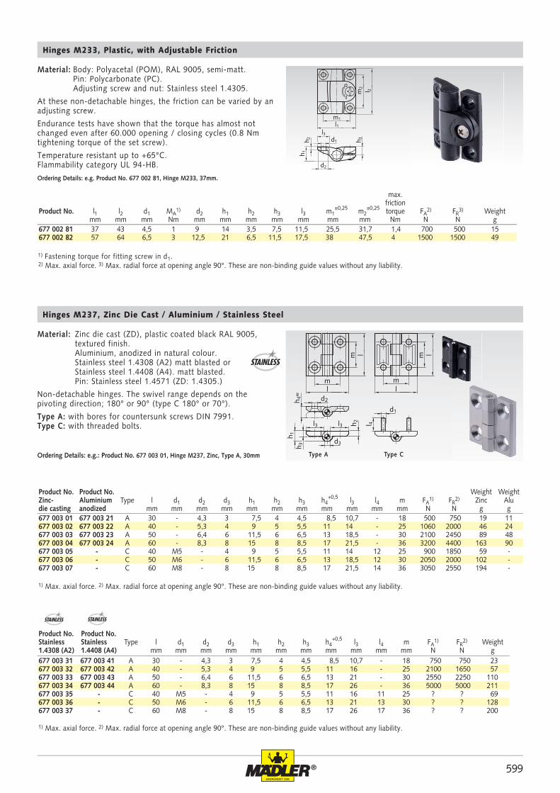
599®
677 003 01 677 003 21 A 30 - 4,3 3 7,5 4 4,5 8,5 10,7 - 18 500 750 19 11677 003 02 677 003 22 A 40 - 5,3 4 9 5 5,5 11 14 - 25 1060 2000 46 24677 003 03 677 003 23 A 50 - 6,4 6 11,5 6 6,5 13 18,5 - 30 2100 2450 89 48677 003 04 677 003 24 A 60 - 8,3 8 15 8 8,5 17 21,5 - 36 3200 4400 163 90677 003 05 - C 40 M5 - 4 9 5 5,5 11 14 12 25 900 1850 59 -677 003 06 - C 50 M6 - 6 11,5 6 6,5 13 18,5 12 30 2050 2000 102 -677 003 07 - C 60 M8 - 8 15 8 8,5 17 21,5 14 36 3050 2550 194 -
d1
l 4
m
ml
l
d2
h 2l3l3
h 3h 1
d3
ml
m l
h 4≈
677 003 31 677 003 41 A 30 - 4,3 3 7,5 4 4,5 8,5 10,7 - 18 750 750 23677 003 32 677 003 42 A 40 - 5,3 4 9 5 5,5 11 16 - 25 2100 1650 57677 003 33 677 003 43 A 50 - 6,4 6 11,5 6 6,5 13 21 - 30 2550 2250 110677 003 34 677 003 44 A 60 - 8,3 8 15 8 8,5 17 26 - 36 5000 5000 211677 003 35 - C 40 M5 - 4 9 5 5,5 11 16 11 25 ? ? 69677 003 36 - C 50 M6 - 6 11,5 6 6,5 13 21 13 30 ? ? 128677 003 37 - C 60 M8 - 8 15 8 8,5 17 26 17 36 ? ? 200
677 002 81 37 43 4,5 1 9 14 3,5 7,5 11,5 25,5 31,7 1,4 700 500 15677 002 82 57 64 6,5 3 12,5 21 6,5 11,5 17,5 38 47,5 4 1500 1500 49
m1
l1l3
l 2m2
d1
d2
h 1
h 3h 2Hinges M237, Zinc Die Cast / Aluminium / Stainless Steel
Material: Zinc die cast (ZD), plastic coated black RAL 9005, textured finish. Aluminium, anodized in natural colour. Stainless steel 1.4308 (A2) matt blasted or Stainless steel 1.4408 (A4). matt blasted. Pin: Stainless steel 1.4571 (ZD: 1.4305.)
Non-detachable hinges. The swivel range depends on the pivoting direction; 180° or 90° (type C 180° or 70°).
Type A: with bores for countersunk screws DIN 7991.Type C: with threaded bolts.
Product No. Product No. Weight WeightZinc- Aluminium Type l d1 d2 d3 h1 h2 h3 h4
+0,5 l3 l4 m FA1) FR
2) Zinc Aludie casting anodized mm mm mm mm mm mm mm mm mm mm mm N N g g
Product No. Product No.Stainless Stainless Type l d1 d2 d3 h1 h2 h3 h4
+0,5 l3 l4 m FA1) FR
2) Weight1.4308 (A2) 1.4408 (A4) mm mm mm mm mm mm mm mm mm mm mm N N g
Type A Type COrdering Details: e.g.: Product No. 677 003 01, Hinge M237, Zinc, Type A, 30mm
STAINLESS STAINLESS
max.friction
Product No. l1 l2 d1 MA1) d2 h1 h2 h3 l3 m1
±0,25 m2±0,25 torque FA
2) FR3) Weight
mm mm mm Nm mm mm mm mm mm mm mm Nm N N g
Material: Body: Polyacetal (POM), RAL 9005, semi-matt. Pin: Polycarbonate (PC). Adjusting screw and nut: Stainless steel 1.4305.
At these non-detachable hinges, the friction can be varied by an adjusting screw.
Endurance tests have shown that the torque has almost not changed even after 60.000 opening / closing cycles (0.8 Nm tightening torque of the set screw).
Temperature resistant up to +65°C. Flammability category UL 94-HB.
Hinges M233, Plastic, with Adjustable Friction
Ordering Details: e.g. Product No. 677 002 81, Hinge M233, 37mm.
STAINLESS
2) Max. axial force. 3) Max. radial force at opening angle 90°. These are non-binding guide values without any liability.
1) Max. axial force. 2) Max. radial force at opening angle 90°. These are non-binding guide values without any liability.
1) Max. axial force. 2) Max. radial force at opening angle 90°. These are non-binding guide values without any liability.
1) Fastening torque for fitting screw in d1.
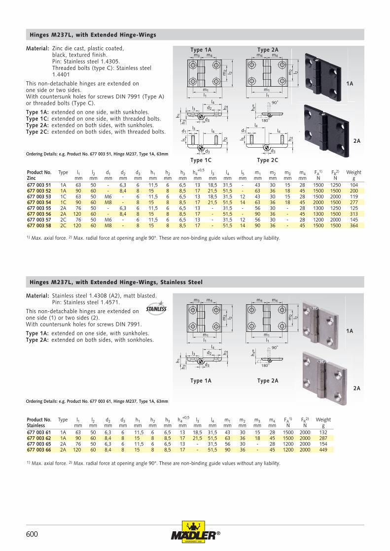
600 ®
m2
l 2
l1
m3 m4
d1
l 5
h 2
d3
h 1h 3
d2
l4l3
h 2
d3
l4l4
d1
l 5 h 2
d3
l4l3
m1
m4 m4
m1l1
m2
l 2
90
180
h 4≈
677 003 51 1A 63 50 - 6,3 6 11,5 6 6,5 13 18,5 31,5 - 43 30 15 28 1500 1250 104677 003 52 1A 90 60 - 8,4 8 15 8 8,5 17 21,5 51,5 - 63 36 18 45 1500 1500 200 677 003 53 1C 63 50 M6 - 6 11,5 6 6,5 13 18,5 31,5 12 43 30 15 28 1500 2000 119677 003 54 1C 90 60 M8 - 8 15 8 8,5 17 21,5 51,5 14 63 36 18 45 2000 1500 277677 003 55 2A 76 50 - 6,3 6 11,5 6 6,5 13 - 31,5 - 56 30 - 28 1300 1250 125677 003 56 2A 120 60 - 8,4 8 15 8 8,5 17 - 51,5 - 90 36 - 45 1300 1500 313677 003 57 2C 76 50 M6 - 6 11,5 6 6,5 13 - 31,5 12 56 30 - 28 1200 2000 145677 003 58 2C 120 60 M8 - 8 15 8 8,5 17 - 51,5 14 90 36 - 45 1500 1500 364
1A
2A
m2
l 2
l1
m3 m4
h 2
d3
h 1h 3
d2
l4l3
m1
m4 m4
m1l1
m2
l 2
90
180
h 4≈
677 003 61 1A 63 50 6,3 6 11,5 6 6,5 13 18,5 31,5 43 30 15 28 1500 2000 132677 003 62 1A 90 60 8,4 8 15 8 8,5 17 21,5 51,5 63 36 18 45 1500 2000 287 677 003 65 2A 76 50 6,3 6 11,5 6 6,5 13 - 31,5 56 30 - 28 1200 2000 154677 003 66 2A 120 60 8,4 8 15 8 8,5 17 - 51,5 90 36 - 45 1200 2000 449
1A
2A
Hinges M237L, with Extended Hinge-Wings
Material: Zinc die cast, plastic coated, black, textured finish. Pin: Stainless steel 1.4305. Threaded bolts (type C): Stainless steel 1.4401
This non-detachable hinges are extended on one side or two sides. With countersunk holes for screws DIN 7991 (Type A) or threaded bolts (Type C).
Type 1A: extended on one side, with sunkholes. Type 1C: extended on one side, with threaded bolts. Type 2A: extended on both sides, with sunkholes. Type 2C: extended on both sides, with threaded bolts.
Ordering Details: e.g. Product No. 677 003 51, Hinge M237, Type 1A, 63mm
Type 1A Type 2A
Type 2CType 1C
Product No. Type l1 l2 d1 d2 d3 h1 h2 h3 h4+0,5 l3 l4 l5 m1 m2 m3 m4 FA
1) FR2) Weight
Zinc mm mm mm mm mm mm mm mm mm mm mm mm mm mm mm mm N N g
Hinges M237L, with Extended Hinge-Wings, Stainless Steel
Type 1A Type 2A
Product No. Type l1 l2 d2 d3 h1 h2 h3 h4+0,5 l3 l4 m1 m2 m3 m4 FA
1) FR2) Weight
Stainless mm mm mm mm mm mm mm mm mm mm mm mm mm mm N N g
Material: Stainless steel 1.4308 (A2), matt blasted. Pin: Stainless steel 1.4571.
This non-detachable hinges are extended on one side (1) or two sides (2). With countersunk holes for screws DIN 7991.
Type 1A: extended on one side, with sunkholes. Type 2A: extended on both sides, with sonkholes.
Ordering Details: e.g. Product No. 677 003 61, Hinge M237, Type 1A, 63mm
STAINLESS
1) Max. axial force. 2) Max. radial force at opening angle 90°. These are non-binding guide values without any liability.
1) Max. axial force. 2) Max. radial force at opening angle 90°. These are non-binding guide values without any liability.
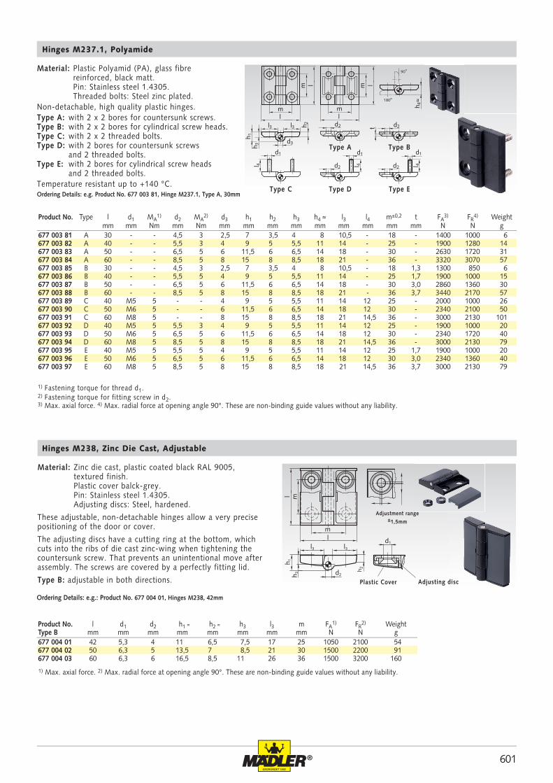
601®
677 004 01 42 5,3 4 11 6,5 7,5 17 25 1050 2100 54677 004 02 50 6,3 5 13,5 7 8,5 21 30 1500 2200 91677 004 03 60 6,3 6 16,5 8,5 11 26 36 1500 3200 160
ml
ml
l3 l3
h 3
h 2
h 1
d2
d1
d1
m
m
l 4
m
ml l
l l
d2h 2l3l3
h 3h 1
d3
d1
l 4d2
d1
l 4d2
d2t
h 4≈180
90
677 003 81 A 30 - - 4,5 3 2,5 7 3,5 4 8 10,5 - 18 - 1400 1000 6677 003 82 A 40 - - 5,5 3 4 9 5 5,5 11 14 - 25 - 1900 1280 14677 003 83 A 50 - - 6,5 5 6 11,5 6 6,5 14 18 - 30 - 2630 1720 31677 003 84 A 60 - - 8,5 5 8 15 8 8,5 18 21 - 36 - 3320 3070 57677 003 85 B 30 - - 4,5 3 2,5 7 3,5 4 8 10,5 - 18 1,3 1300 850 6677 003 86 B 40 - - 5,5 5 4 9 5 5,5 11 14 - 25 1,7 1900 1000 15677 003 87 B 50 - - 6,5 5 6 11,5 6 6,5 14 18 - 30 3,0 2860 1360 30677 003 88 B 60 - - 8,5 5 8 15 8 8,5 18 21 - 36 3,7 3440 2170 57677 003 89 C 40 M5 5 - - 4 9 5 5,5 11 14 12 25 - 2000 1000 26677 003 90 C 50 M6 5 - - 6 11,5 6 6,5 14 18 12 30 - 2340 2100 50677 003 91 C 60 M8 5 - - 8 15 8 8,5 18 21 14,5 36 - 3000 2130 101677 003 92 D 40 M5 5 5,5 3 4 9 5 5,5 11 14 12 25 - 1900 1000 20677 003 93 D 50 M6 5 6,5 5 6 11,5 6 6,5 14 18 12 30 - 2340 1720 40677 003 94 D 60 M8 5 8,5 5 8 15 8 8,5 18 21 14,5 36 - 3000 2130 79677 003 95 E 40 M5 5 5,5 5 4 9 5 5,5 11 14 12 25 1,7 1900 1000 20677 003 96 E 50 M6 5 6,5 5 6 11,5 6 6,5 14 18 12 30 3,0 2340 1360 40677 003 97 E 60 M8 5 8,5 5 8 15 8 8,5 18 21 14,5 36 3,7 3000 2130 79
Product No. l d1 d2 h1 ≈ h2 ≈ h3 l3 m FA1) FR
2) WeightType B mm mm mm mm mm mm mm mm N N g
Hinges M238, Zinc Die Cast, Adjustable
Material: Zinc die cast, plastic coated black RAL 9005, textured finish. Plastic cover balck-grey. Pin: Stainless steel 1.4305. Adjusting discs: Steel, hardened.
These adjustable, non-detachable hinges allow a very precise positioning of the door or cover.
The adjusting discs have a cutting ring at the bottom, which cuts into the ribs of die cast zinc-wing when tightening the countersunk screw. That prevents an unintentional move after assembly. The screws are covered by a perfectly fitting lid.
Type B: adjustable in both directions.
Ordering Details: e.g.: Product No. 677 004 01, Hinges M238, 42mm
Adjusting disc
Adjustment range±1,5mm
Plastic Cover
Hinges M237.1, Polyamide
Ordering Details: e.g. Product No. 677 003 81, Hinge M237.1, Type A, 30mm
Material: Plastic Polyamid (PA), glass fibre reinforced, black matt. Pin: Stainless steel 1.4305. Threaded bolts: Steel zinc plated. Non-detachable, high quality plastic hinges. Type A: with 2 x 2 bores for countersunk screws. Type B: with 2 x 2 bores for cylindrical screw heads. Type C: with 2 x 2 threaded bolts. Type D: with 2 bores for countersunk screws and 2 threaded bolts. Type E: with 2 bores for cylindrical screw heads and 2 threaded bolts. Temperature resistant up to +140 °C.
Type A Type B
Type DType C Type E
Product No. Type l d1 MA1) d2 MA
2) d3 h1 h2 h3 h4 ≈ l3 l4 m±0,2 t FA3) FR
4) Weightmm mm Nm mm Nm mm mm mm mm mm mm mm mm mm N N g
1) Max. axial force. 2) Max. radial force at opening angle 90°. These are non-binding guide values without any liability.
1) Fastening torque for thread d1. 2) Fastening torque for fitting screw in d2. 3) Max. axial force. 4) Max. radial force at opening angle 90°. These are non-binding guide values without any liability.
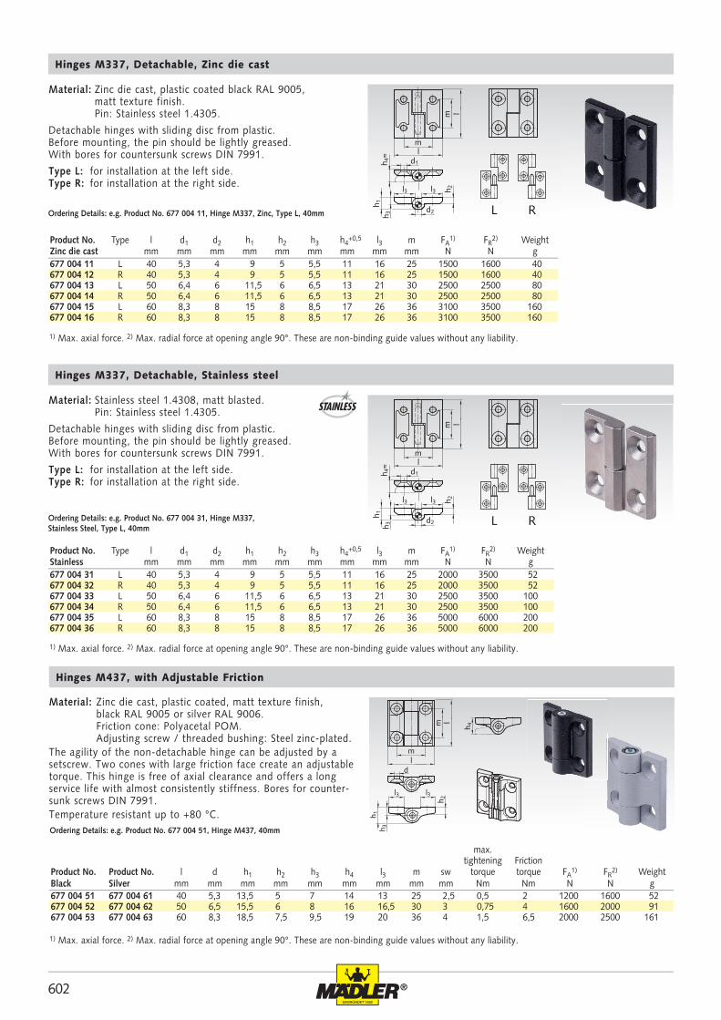
602 ®
677 004 51 677 004 61 40 5,3 13,5 5 7 14 13 25 2,5 0,5 2 1200 1600 52677 004 52 677 004 62 50 6,5 15,5 6 8 16 16,5 30 3 0,75 4 1600 2000 91677 004 53 677 004 63 60 8,3 18,5 7,5 9,5 19 20 36 4 1,5 6,5 2000 2500 161
ml
m l
d
h 3
h 4
h 1
l3 l3
h 2
677 004 11 L 40 5,3 4 9 5 5,5 11 16 25 1500 1600 40677 004 12 R 40 5,3 4 9 5 5,5 11 16 25 1500 1600 40677 004 13 L 50 6,4 6 11,5 6 6,5 13 21 30 2500 2500 80677 004 14 R 50 6,4 6 11,5 6 6,5 13 21 30 2500 2500 80677 004 15 L 60 8,3 8 15 8 8,5 17 26 36 3100 3500 160677 004 16 R 60 8,3 8 15 8 8,5 17 26 36 3100 3500 160
677 004 31 L 40 5,3 4 9 5 5,5 11 16 25 2000 3500 52677 004 32 R 40 5,3 4 9 5 5,5 11 16 25 2000 3500 52677 004 33 L 50 6,4 6 11,5 6 6,5 13 21 30 2500 3500 100677 004 34 R 50 6,4 6 11,5 6 6,5 13 21 30 2500 3500 100677 004 35 L 60 8,3 8 15 8 8,5 17 26 36 5000 6000 200677 004 36 R 60 8,3 8 15 8 8,5 17 26 36 5000 6000 200
h 2l3l3
h 3h 1
d2
d1
m l
ml
RL
h 4≈
h 2l3l3
h 3h 1
d2
d1
m lml
RL
h 4≈
Material: Zinc die cast, plastic coated, matt texture finish, black RAL 9005 or silver RAL 9006. Friction cone: Polyacetal POM. Adjusting screw / threaded bushing: Steel zinc-plated.The agility of the non-detachable hinge can be adjusted by a setscrew. Two cones with large friction face create an adjustable torque. This hinge is free of axial clearance and offers a long service life with almost consistently stiffness. Bores for counter-sunk screws DIN 7991. Temperature resistant up to +80 °C.
Hinges M437, with Adjustable Friction
Ordering Details: e.g. Product No. 677 004 51, Hinge M437, 40mm
max. tightening Friction
Product No. Product No. l d h1 h2 h3 h4 l3 m sw torque torque FA1) FR
2) WeightBlack Silver mm mm mm mm mm mm mm mm mm Nm Nm N N g
Hinges M337, Detachable, Zinc die cast
Ordering Details: e.g. Product No. 677 004 11, Hinge M337, Zinc, Type L, 40mm
Product No. Type l d1 d2 h1 h2 h3 h4+0,5 l3 m FA
1) FR2) Weight
Zinc die cast mm mm mm mm mm mm mm mm mm N N g
Material: Zinc die cast, plastic coated black RAL 9005, matt texture finish. Pin: Stainless steel 1.4305.
Detachable hinges with sliding disc from plastic. Before mounting, the pin should be lightly greased. With bores for countersunk screws DIN 7991.
Type L: for installation at the left side. Type R: for installation at the right side.
Hinges M337, Detachable, Stainless steel
Ordering Details: e.g. Product No. 677 004 31, Hinge M337, Stainless Steel, Type L, 40mm
Product No. Type l d1 d2 h1 h2 h3 h4+0,5 l3 m FA
1) FR2) Weight
Stainless mm mm mm mm mm mm mm mm mm N N g
Material: Stainless steel 1.4308, matt blasted. Pin: Stainless steel 1.4305.
Detachable hinges with sliding disc from plastic. Before mounting, the pin should be lightly greased. With bores for countersunk screws DIN 7991.
Type L: for installation at the left side. Type R: for installation at the right side.
STAINLESS
1) Max. axial force. 2) Max. radial force at opening angle 90°. These are non-binding guide values without any liability.
1) Max. axial force. 2) Max. radial force at opening angle 90°. These are non-binding guide values without any liability.
1) Max. axial force. 2) Max. radial force at opening angle 90°. These are non-binding guide values without any liability.
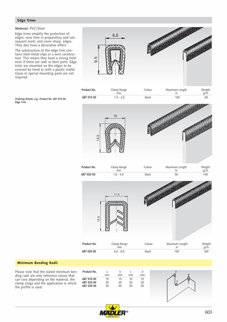
603®
687 020 00 1,0 - 4,0 50 140
687 030 00 4,0 - 6,0 100 160
687 010 00 15 15 10 10 687 020 00 30 20 20 20 687 030 00 50 40 30 30
687 010 00 1,0 - 2,0 100 65
Material: PVC/Steel.
Edge trims simplify the protection of edges, save time in preparatory and sub-sequent work, and cover sharp edges. They also have a decorative effect.
The substructure of the edge trim con-tains steel metal clips or a wire construc-tion. This means they have a strong hold even if there are radii or bent parts. Edge trims are mounted on the edges to be covered by hand or with a plastic mallet. Glues or special mounting parts are not required.
Edge Trims
Ordering Details: e.g.: Product No. 687 010 00, Edge Trim
Please note that the stated minimum ben-ding radii are only reference values that can vary depending on the material, the clamp range and the application in which the profile is used.
Minimum Bending Radii
Product No. Clamp Range Colour Maximum Length Weight mm m g/m
Product No. Clamp Range Colour Maximum Length Weight mm m g/m
Product No. Clamp Range Colour Maximum Length Weight mm m g/m
Product No. a b c d mm mm mm mm
black
black
black
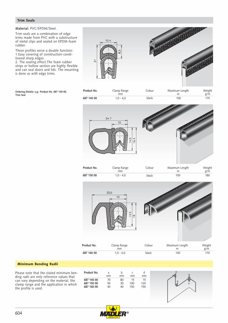
604 ®
687 140 00 1,0 - 4,0 100 175
687 150 00 1,0 - 4,0 100 180
687 160 00 1,0 - 4,0 100 170
687 140 00 70 80 15 15 687 150 00 50 30 100 120 687 160 00 40 40 150 150
Material: PVC/EPDM/Steel.
Trim seals are a combination of edge trims made from PVC with a substructure of metal clips and sealed on EPDM-foam rubber.
These profiles serve a double function: 1.Easy covering of construction-condi-tioned sharp edges. 2. The sealing effect.The foam rubber strips or hollow section are highly flexible and can seal doors and lids. The mounting is done as with edge trims.
Trim Seals
Ordering Details: e.g.: Product No. 687 140 00, Trim Seal
Product No. Clamp Range Colour Maximum Length Weight mm m g/m
Product No. Clamp Range Colour Maximum Length Weight mm m g/m
Product No. Clamp Range Colour Maximum Length Weight mm m g/m
Please note that the stated minimum ben-ding radii are only reference values that can vary depending on the material, the clamp range and the application in which the profile is used.
Minimum Bending Radii
Product No. a b c d mm mm mm mm
black
black
black