fatigue i
DESCRIPTION
FATIGUE ITRANSCRIPT

FATIGUE PROPERTIES – I
UNIAXIAL STRESS FATIGUE
Fatigue and EnduranceMachine parts and structural members are frequently subjected to
time varying loads and stresses. It is important to know the strength of materials under such conditions. The materials are known to fail under reversal of stress at much smaller stress amplitudes than their static ultimate / fracture / strengths. The number of cycles applied in static test is just one-quarter of a cycle. As the number of cycles increases, the amplitude of reversed stress causing failure decreases. This is why machine parts fail soon at low levels of stress amplitude, when working at high speeds. This phenomenon of the decreased resistance of a material to repeated stresses is called fatigue. The testing of a material by the application of such stresses is known as fatigue test or endurance test.
Nature of Fatigue FailuresThe nature of fatigue failure is different from that of static failure.
In general before the final fracture / failure, a sort of plastic flow or stretching of crystals occurs. The final fractured surface has a fibrous structure, resembling that of a static brittle fracture. Fatigue fracture normally starts from a crack, where the stress is concentrated and progresses till the part is completely separated. The final separation occurs suddenly, when the crack has progressed to that extent that the remaining area is just not enough to withstand the magnitude of the stress and practically a static brittle fracture finally occurs. It is confirmed by the small area of the final fracture resembling that of a static brittle fracture. But the surface of the progressively cracked area normally has a mirror finish, because of the repeated closing and opening and rubbing / abrasion of the surface. (Read books to know of mechanical, sonic, thermal, pitting/fretting, corrosive fatigues)
Types of Time-varying StressesFourier series can express any wave shape as the sum of sinusoidal waves of different amplitudes and frequencies. Therefore the simple fatigue tests focus attention only on a sinusoidal load – stress pattern. There are three situations of loads:
(1) General (Fluctuating) (2) Completely Reversed (3) Repeated
In the stress wave there are minimum and maximum values: Smax, Smin. Then in general
Mean stress, Sm = (Smax + Smin)/2Stress-amplitude, Sa = (Smax - Smin)/2
1

Students may sketch each case to understand
1. General (Fluctuating) S = Sm + Sa sin 2t/T
Sm = (Smax + Smin)/2; Sa = (Smax - Smin)/2
Smax = Sm + Sa; Smin = Sm - Sa
2. Completely Reversed S= Sa sin 2t/T
Sm = 0Smin = - SmaxSa = Smax
3. RepeatedS= Sa(1 + sin 2t/T)
Smin = 0 & Smax = + 2 SaOrSmax = 0 & Smin = - 2 Sa
Cases 2 and 3 are only special cases of case 1.
COMPLETELY REVERSED STRESS
Fatigue TestsThe mostly used type of time-varying stress in fatigue tests is
completely reversed stress. The specimens may be subjected to different type of reversed stresses.
1 Axial2 Torsion3 Bendinga) Rotating simply supported beam with two-point loads b) Cantilever beam with reversing end load c) Rotating Cantilever beam with end load
The mostly used test is reversed bending in a rotating beam
with four-point loads. (Refer Fig 4.17 in Printed Material)
2

The two ends of the beam-like specimen of circular cross section tapering towards the middle are supported on swivel bearings. The gage length of the specimen lies in the mid-portion of the specimen. At the ends of the gage length two more bearings are provided, through which two equal weights are hung. Now the gage length has pure bending state. When the specimen is rotated from one end, the fibers in the specimen are exposed to alternating tensile and compressive bending stress. The number of cycles to fracture is recorded for one set of two equal weights applied.
Thus, for each of the stress amplitudes, a separate specimen with separate different set of two weights is used and the corresponding number of cycles observed. Thus for each point in Sa-N plot, one specimen needs to be tested to fracture.
The Sa–N relation is plotted and is called S-N curve. The amplitude of stress Sa is called as endurance / fatigue strength for the particular life, expressed as number of cycles, N and denoted as Se.
In specifying the endurance/fatigue strength, therefore, both the stress and the corresponding number of cycles to failure must be stated.
It should be noted that there is another term endurance limit Sel, which is different from endurance strength. Most ferrous alloys, say steels have endurance limit, a stress amplitude below the magnitude of which their life is infinite. This will not apply to all materials.
Design CriterionIn general, for a given life of N cycles, fatigue failure occurs when
the amplitude of completely reversed stress Sa = Se. For safety / no failure at N cycles, then
Sa S = Se (1)If a factor of safety is required
Sa Sew = Se / FS (1A)
Fitting an S-N curve Since separate specimens are used to get each point in an S-N
curve, there is wide scatter in any experimental S-N curve data. The scattered data is suitably fitted in to an S-N curve. Since the number of cycles to fracture is very high, in the order of 106 or more, N-coordinate is usually log N. The graph will be S – log N curve. Sometimes the plot is log S – log N curve.
A very common form of S-N curve for fatigue failure is fitted as
NSn = q (constant) (2)
3

[Here q has dimension of (Stress)n , since N has no dimension]
For convenience, many a time, the stress is normalized arbitrarily with a constant stress S0 and expressed as
N(S/S0)n = Q (constant) (2A)[Here Q has no dimension: dimensionless]
This type of curve fit has some limitations. At least there are two limitations, one at low cycle and the other at very high cycle.
1) At low cycle fatigue range, that is, near zero cycle, N 0, S tends to infinity in (2). But we know it is static case and S must be either the yield strength SY or the ultimate strength Su as per the choice of failure criterion made.
2) For most ferrous group of metals, the S-N curve becomes asymptotic to a horizontal line with increasing N. The stress amplitude, Se, corresponding to this asymptote is called the endurance / fatigue limit, Sel. This means any stress amplitude below this value, theoretically, can be applied for infinite number of cycles without fatigue failure. Most of the conservative designs are made based on this limiting stress amplitude Sel, which is the lowest.
When N tends to infinity, S tends to zero in (2), instead of limiting to endurance limit Sel.
Therefore, some modifications have been proposed in (2) to overcome these two limitations, as below.
(N + No) (Sa - Sel)n = B (3)
Here in (3) if the static design criterion is, say SY at N = 0,No = B/( SY - Sel )n (3A)
When Sa = Sel in (3), N tends to infinity, confirming the endurance limit.
However for most purposes, where it is neither very low cycle nor very high cycle fatigue, the expression (2) or (2A) is used conveniently and satisfactorily.
It must be kept in mind that N represents the number of cycles to fracture at stress amplitude of S in completely reversed cycle fatigue.
4
CUMULATIVE DAMAGE – MINER’S RULE
Machine and structural members are not always subjected to the same steady stress amplitude, but some times to higher stress for some number of cycles and other times to lower stress for another number of cycles. When such situation arises, how can the fatigue strength be assessed and how can one find the life spent and remaining?
One of the propositions to account for having run the parts for partial life with different stress amplitudes and for calculating the remaining life is the Miner’s Cumulative Damage Rule.
According to this simple linear rule, a part has expended its full life if the stress amplitude is Si and it is run for Ni cycles under completely reversed cycle so that it satisfies (2) or (2A),
NiSin = q (4)
Ni (Si /S0)n = Q (4A)
That is, its full life is Ni cycles at Si and it has been run to its full life of Ni itself and this condition is therefore expressed as
Li = Ni/Ni = 1 (5)
At Si, if it is not run to its full life of N i cycles, but was run only for a lower number of cycles ni < Ni, the proportion of life expended is only
Li = ni/Ni < 1 (at Si) (6)
If it happens that the material is subjected to many such different stress amplitudes Si for the corresponding number of cycles ni, then the total amount of life expended is
L = Li = ni/Ni 1 (7)
Expression (7) is the Miner’s rule for cumulative damage.
Example 1: The fatigue property of the material of certain part was fitted for N(in number of cycles) and S (in MPa) to be
N (S/600)6 = 30 x 103
a) If the part was subjected to the following sets of stress and number of cycles, find the life expended so far.
5

Given Data n = 5 x 10⁴ 105 5 x 10⁵ Cycles of RunS = 450 400 300 MPa
b) If it is required to run the part further at S = 400 MPa, find the possible number of cycles for which it could be run further.
c) In stead, if the part has to be run further for104 cycles, what stress amplitude can be applied?
Solution:Calculated from N(S/600)6 = 30 x 103
S = 450 400 300 MPaN = 1.686 x 10⁵ 3.41 x 10⁵ 19.2 x 10⁵ Full-Life Cycles
Using Miner’s rule (7)
a) L = 5 x 10⁴ / 1.686 x 10⁵ + 105 / 3.41 x 10⁵ + 5 x 10⁵ / 19.2 x105
= 1/ 3.372 +1/ 3.41 + 1/ 3.84 = 0.85023
Remaining life LR = 1 – 0.85023 = 0.14977
b) For S= 400 MPa, LR = 0.14977 = n / N = n / 3.41 x 10⁵
n = 0.14977 x 3.41 x 105 = 0.5105 x10⁵ cycles c) For 104 cycles, the unknown is S at n = 104 cycles. Now
LR = 0.14977 = (n / N) N = n / LR = 104 /0.1477 = 6.68 x 10⁴ cycles
Then(S / 600)6 = 30 x 103 / 6.68 x 10⁴
S = 0.8751 x 600 MPa = 525 MPa
EFFECT OF OVER-STRESSING AND UNDER-STRESSING
A part may be over-stressed for some time before a steady state is maintained. It is known that an earlier over-stressing reduces the fatigue strength in the subsequent lower steady stress. Similarly an earlier under-stressing increases the fatigue strength. It has been also noticed that a minimum number of cycles of over-stressing is needed to cause damage. This is really complicated in nature and any attempt to take in to account effect of the order in which, the over- or under-stressing is applied is only suggestive and a designer should consider every case individually and separately.
6

One such method due to Joseph Marin [Ref 1] / Corten & Dolan [Ref 2] is explained here. Another method by Manson can be seen in literature [Ref 3]
The reference stress-amplitude is S1 the first applied stress in the use of Marin’s method. Any run above this reference stress is construed to be overstressing, causing more damage and reducing endurance life. Like wise any run below this reference stress, strengthens the material and prolongs the fatigue life.
According to this rule, if ni cycles are run at stress amplitude Si, then the actual life expended is not ni but ni (Si / S1)d ,where d 0. Then the equivalence of expression (7) becomes
L = Li = (ni/Ni) (Si / S1)d 1 (8)
If d = 0, (8) reduces to Miner’s rule (7),( since anything raised to zero is ONE)
References1 Marin, J, “Significance of Material Properties in Design for
Fatigue Loading”, Machine Design, Jan-March, 19572 Corten, and Dolan, “Cumulative Fatigue Damage”, Proc. Inst.
Mech Eng,65, London, 1956, p2353 Shigley, Joseph E (Original in British units) / N. Siva Prasad &
others of IIT Madras (in SI units) , Mechanical Engineering Design, Tata MGraw Hill, 2003,
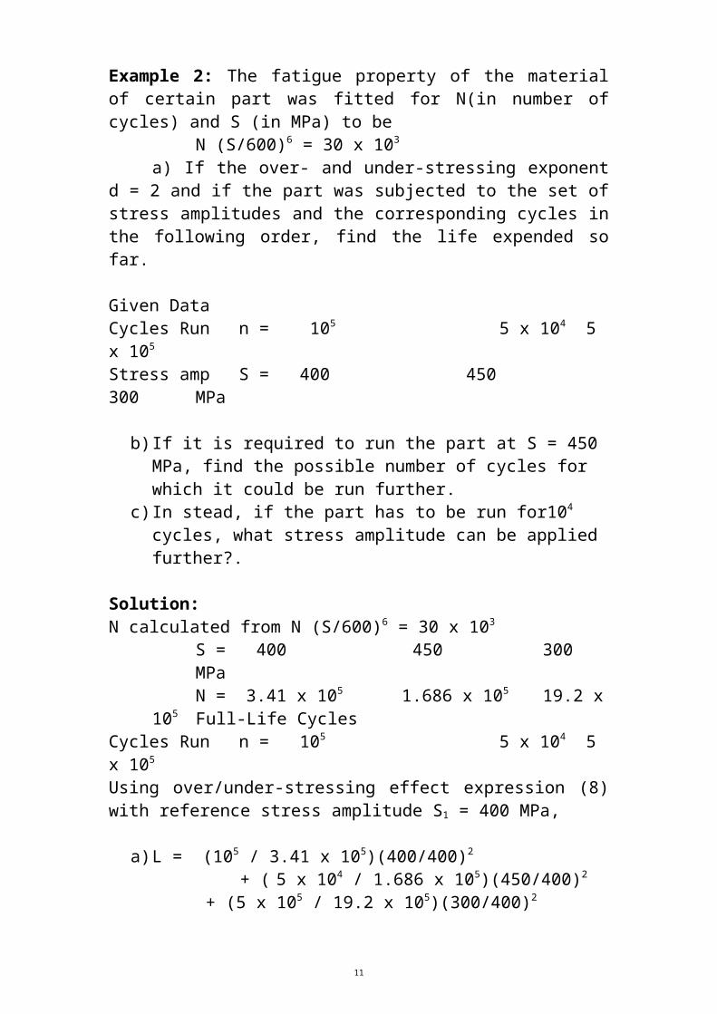
Example 2: The fatigue property of the material of certain part was fitted for N(in number of cycles) and S (in MPa) to be
N (S/600)6 = 30 x 103
a) If the over- and under-stressing exponent d = 2 and if the part was subjected to the set of stress amplitudes and the corresponding cycles in the following order, find the life expended so far.
Given DataCycles Run n = 105 5 x 10⁴ 5 x 10⁵
Stress amp S = 400 450 300 MPa
b) If it is required to run the part at S = 450 MPa, find the possible number of cycles for which it could be run further.
c) In stead, if the part has to be run for104 cycles, what stress amplitude can be applied further?.
Solution:N calculated from N (S/600)6 = 30 x 103
S = 400 450 300 MPa
7

N = 3.41 x 10⁵ 1.686 x 10⁵ 19.2 x 10⁵ Full-Life CyclesCycles Run n = 105 5 x 10⁴ 5 x 10⁵
Using over/under-stressing effect expression (8) with reference stress amplitude S1 = 400 MPa,
a) L = (105 / 3.41 x 10⁵)(400/400)2
+ ( 5 x 10⁴ / 1.686 x 10⁵)(450/400)2 + (5 x 10⁵ / 19.2 x 10⁵)(300/400)2
= 1/ 3.41 + 1.265625/ 3.372 + 0.5625/ 3.84 = 0.8150
Remaining life LR = 1 – 0.8150 = 0.1850
b) For S = 450 MPa, LR = 0.1850 = (n / 1.686 x 10⁵) (450/400)2 = (n / 1.686 x 10⁵) (1.265625)
n = 0.1850 x 1.686x 105 /1.265625 = 2.4645 x10⁴ cycles c) For 104 cycles,
LR = 0.1850 = (n / N) (S/400)2 (A)Now n = 104 cycles; S is unknown and N is also not known as long as S is unknown. But N can be found in terms of S from S-N relation (2A).
N (S/600)6 = 30 x 103 Then
1/N = (S/600)6 /30 x 103
Therefore, substituting in (A)LR = 0.1850 =104 [(S/600)6 /30 x 103] (S/400)2
= 104 (S)8/(4002 x 6006 x 30 x 103) S = 504 MPa
EFFECT OF MEAN STRESS ON FATIGUE STRENGTH So far only completely reversed stress was considered. In practice there are situations, where a static mean stress exists; over and above it, an alternating stress is superposed. A simple example is the spokes of a bicycle wheel. Initially the spokes are tensioned. When the spokes are in vertical position, added compression stress reduces the tensile stress and in its horizontal position added tensile stress increases the tensile stress. This alternates in every rotation.
This problem is viewed at its two extreme situations.1 First extreme is the condition of failure due to only static stress,
without alternating stress. Failure then would occur either at yield stress or at ultimate stress, as the choice of a designer.
8

Let us choose yield stress SY. Then Sm ≤ SY
2 Next extreme is the condition of failure due to only completely reversed stress, without static mean stress. Failure occurs at endurance strength Se at a given number of cycles N (or endurance limit Sel, as the choice may be).
Then Sa ≤ Se
SketchIf the mean stress Sm on x-axis and the completely reversed stress
amplitude Sa on the y-axis are plotted, the two extremes provide one intercept point on x-axis (SY,0) and another intercept point on y-axis (0, Se).
What will be the relation in between these two extreme points, when there is a combination of the two, is the question.
There are four propositions generally known (Sketches). Two are linear, the third is parabolic and the fourth is elliptical relation.
Soderberg (Linear): (Sa/Se) + (Sm/SY) = 1 (9)
Modified Goodman (Linear): (Sa/Se) + (Sm/Su) = 1 (10) Gerber (Parabolic) : (Sa/Se) + (Sm/Su)2 = 1 (11)
Elliptical* (Sa/Se) 2 + (Sm/Su)2 = 1 (12)
*The Elliptic relation can be shown to represent energy. Here sometimes SY is used in place of Su.
Soderberg or Modified Goodman relations are the mostly used.
The Soderberg relation (9) can be rewritten as
Sa + (Se/SY) Sm = Se (9A)For no failure / just failure
Sa + (Se/SY) Sm Se (9B)
This (9B) is rewritten as. Sa + p Sm Se (9C)
where p = (Se/SY)
Further (9C) can be expressed in the same form as (1), as(Sa)eq Se (9D)*
9

where (Sa)eq = Sa + p Sm
*(9D) is used later also in combined stress status.
Comparing (1) and (9D) and using (2) and (2A), with the new higher (Sa)eq, it is clear that the life N will be smaller. This is due to the effect of added mean stress.
It should be noted that the effect is assumed to be the same, for compressive (-) or tensile (+) mean stress, even though, in practice, compressive mean stress improves the fatigue life. (See Figs 4.15 & 4.16 in printed notes)
Langer conditionWhile all these refer to a mean and a reversed stress combination at
high cycle fatigue, a check at low cycle, especially at very first cycle for static failure is essential. When the magnitude of Smax = (Sm + Sa) exceeds the static failure strength, ether SY or Su (to be specified), static failure would occur. Langer suggested a simple and obvious relation, taking yield as static failure criterion.
Smax / SY 1 (13) Or since Smax = Sm + Sa,
(Sa/ SY) + (Sm/SY) 1 (13A)(Sa + Sm) SY (13B)
The condition (13A) is a straight line passing backward at 45 degrees from SY (at Sm axis).
Note: The condition (13 or 13A or 13B) is automatically satisfied for Soderberg relation as long as Se < SY (which is the case in actual materials). For the other 3 relations, a check is necessary for the factor of safety during the first cycle [Ref 3]. Ask for sketch in class!
For Modified Goodman (Linear) case, there is a point beyond that, (10) will not be applicable; only (13 B) will apply. This point is the point of intersection of these two. Solving, we get the coordinates as:
Sm = Su (SY – Se)/(Su – Se) & Sa = Se (Su - SY)/(Su – Se).It will be clearer in a sketch.
Thus the full range of MGM relation is not applicable and the toe at the higher side of Sm is shortened. (Draw sketch & explain)
EXAMPLES
10
Example 1: A bolt of 3000 mm2 in cross section is made of a material with a fatigue strength for complete stress reversal Se = 240 MPa for a given number of cycles, a tensile yield of SY = 360 MPa and a tensile ultimate strength of Su = 400 MPa. The bolt is subjected to a static mean load of 18 x 104 N. What completely reversed fatigue load would cause failure at same number of cycles? Use: a) Soderberg , b) Modified Goodman, c) Gerber and d) Elliptic relation and check for first cycle failure.
Solution:Soderberg relation
Sa/Se + Sm/SY =1Sm = P/A =18 x 104 / 3000 = 60 MPaSm/ SY = 60/360 = 1/6Sa = (1 –1/6) Se = 5/6 x 240 = 200 MPaPa = Sa x A = 200 x 3000 = 60 x 104 N
Check for Langer condition: Sa + Sm = 200 + 60 = 260 < 360 = SY
Safe.
Modified Goodman relationSa/Se + Sm/Su =1Sm/ Su = 60/400 = 3/20Sa = (1 –3/20) Se = 17/20 x 240 = 204 MPaPa = Sa x A = 204 x 3000 = 61.2 x 10⁴ N
Check for Langer condition: Sa + Sm = 204 + 61.2 = 265.2 < 360 = SY
Safe.Gerber relation:Using SY:
Sa/Se +(Sm/SY)2 =1
Sa = (1 –1/36) Se = 35/36 x 240 = 233.33 MPaPa = 233.33 x 3000 = 70 x 104 N
Check for Langer condition: Sa + Sm = 233 + 60 = 293 < 360 = SY
Safe.
Using SU:Sa/Se +(Sm/SU)2
=1Sa = (1 – 9/400) Se = 391/400 x 240 = 234.6 MPaPa = 234.6x 3000 = 70.38 x 10⁴ N
Check for Langer condition: Sa + Sm = 234.6 + 60 = 294.6 < 360 = SY
Safe.
Elliptical relation:Using SY:
11

(Sa/Se) 2 +(Sm/SY)2 =1
(Sa/Se) 2 =1- (Sm/SY)2 = 1 – 1/36 = 35/36Sa = 35/36 x Se = 0.986 Se = 0.986 x 240 = 236.64 MPaPa = 71 N
Check for Langer condition: Sa + Sm = 236.64 + 60 = 296.64 < 360 = SY.
Safe.
Using SU:
(Sa/Se) 2 +(Sm/SU)2 =1
(Sa/Se) 2 =1- (Sm/SU)2 = 1 – 9/400 = 391/400Sa = 391/400x Se = 0.988686 Se
= 0.988686 x 240 = 237.28 MPaPa = 71.185 N
Check for Langer condition: Sa + Sm = 237.28 + 60 = 297.28 < 360 = SY.
Safe.
Example 2: A steel cantilever horizontal beam 750 mm long, 100 mm wide and 200 mm deep is subjected to an end down ward fluctuating load, varying from a minimum value of Pmin = 180000 N to a maximum value Pmax. The material has a fatigue strength = 210 MPa at a given number of cycles and a yield strength = 240 MPa. Determine Pmax that will cause fatigue failure, according to Soderberg relation at the same number of cycles.
Solution:
Smin = Pmin x L x c/ I =180000 x 750 x 100 x12 /(100 x 2003)
= 202.5 MPa Sa = (Smax – Smin)/2 and Sm = (Smax + Smin)/2
Soderberg relation is(Sa)/Se + (Sm)/SY =1
Therefore(Smax – Smin)/2Se + (Smax + Smin)/2SY =1(Smax – Smin) + (Smax + Smin)(Se/SY)= 2Se
Let p = Se/SY Therefore,(Smax – Smin) + (Smax + Smin)p = 2SeSmax (1+p) – Smin(1 – p) = 2SeSmax = 2Se/(1+p) – Smin(1 – p)/ (1+p)
12

Now p = Se/SY = 210/240 = 7/8 = 0.875 Therefore,Smax = 2 x 210/1.875 – 202.5 x 0.125/1.875 =210.5 MPa Smin: Pmin = Smax: Pmax
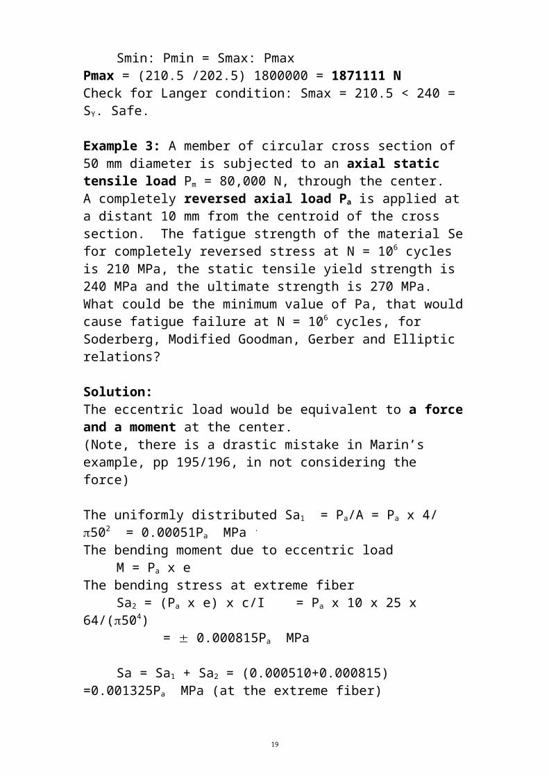
Pmax = (210.5 /202.5) 1800000 = 1871111 N Check for Langer condition: Smax = 210.5 < 240 = SY. Safe.
Example 3: A member of circular cross section of 50 mm diameter is subjected to an axial static tensile load Pm = 80,000 N, through the center. A completely reversed axial load Pa is applied at a distant 10 mm from the centroid of the cross section. The fatigue strength of the material Se for completely reversed stress at N = 106 cycles is 210 MPa, the static tensile yield strength is 240 MPa and the ultimate strength is 270 MPa. What could be the minimum value of Pa, that would cause fatigue failure at N = 106 cycles, for Soderberg, Modified Goodman, Gerber and Elliptic relations?
Solution: The eccentric load would be equivalent to a force and a moment at the center. (Note, there is a drastic mistake in Marin’s example, pp 195/196, in not considering the force)
The uniformly distributed Sa1 = Pa/A = Pa x 4/ 502 = 0.00051Pa MPa .
The bending moment due to eccentric loadM = Pa x e
The bending stress at extreme fiber Sa2 = (Pa x e) x c/I = Pa x 10 x 25 x 64/(504) = 0.000815Pa MPa
Sa = Sa1 + Sa2 = (0.000510+0.000815) =0.001325Pa MPa (at the extreme fiber)
Pa = Sa/0.001325 N
Sm = Pm/A = Pm x 4/ (502) = 0.00051 Pm = 0.00051 x 80000 = 40.8 MPa Sm/ SY = 40.8/240 = 0.17; Sm/Su = 40.8/270 =0.151111
Soderberg:Sa = Se (1-Sm/ SY) = 210 x (1 – 0.17) = 174.3 MPaPa = 174.3/0.001325 = 131320 NCheck for Langer condition: Sa + Sm = 174.3 + 40.8 = 215.1 < 240 = SY.
Safe
Modified Goodman
13

Sa = Se (1-Sm/ Su) = 210 x (1 – 0.151111) = 178.3 MPaPa = 178.3/0.001325 = 134541 NCheck for Langer condition: Sa + Sm = 178.3 + 40.8 = 219.1 < 240 = SY.
Safe
Gerber:
Using SU:
Sa = Se [1-(Sm/ SU)2]= 210 x [1 – (0.1511)2] = 205.2 MPaPa = 205.2/0.001325 = 155164 NCheck for Langer condition: Sa + Sm = 205.2 +40.8 = 246 > 240 = SY. Not safe.Therefore the maximum Sa could be only (240 – 40.8) =199.2 MPa..Pa = 150340 N
[Using SY:
Sa = Se [1-(Sm/ SY)2]= 210 x [1 – (0.17)2] = 204 MPaPa = 204/0.001325 = 153910 NCheck for Langer condition: Sa + Sm = 204 +40.8 = 244.8 > 240 = SY. Not safe.Therefore the maximum Sa could be only (240 – 40.8) =199.2 MPa..Pa = 150340 N]
Elliptic:
Using SU:
Sa =Se [1-(Sm/ SU)2]= 210 x [1 – (0.1511)2] =207.5886 MPaPa = 207.5886/0.001325 = 156671 NCheck for Langer condition: Sa + Sm = 207.59 +40.8 = 248.39> 240 = SY
Not safeTherefore the maximum Sa could be only (240 – 40.8) =199.2 MPa..Pa = 150340 N
[Using SY:
Sa =Se [1-(Sm/ SY)2]= 210 x [1 – (0.17)2] =207 MPaPa = 207/0.001325 = 156184 NCheck for Langer condition: Sa + Sm = 207 +40.8 = 247.8 > 240 = SY Not safeTherefore the maximum Sa could be only (240 – 40.8) =199.2 MPa..Pa = 150340 N]
14

Example 4: (Important):
The fatigue property of the material of certain part was fitted for N(in number of cycles) and S (in MPa) to be
N (S/600)6 = 30 x 103
The over- and under-stressing exponent d = 2. The yield strength of the material is 600 MPa. There is a mean stress Sm = 100 MPa. The part was subjected to a set of stress amplitudes and the corresponding cycles in the following order.
n = 104 104 105 Cycles RunSa = 400 450 300 MPa
a) Find the life expended so far.b) If it is required to run the part at Sa = 450 MPa, find the possible number of cycles for which it could be run further.c) In stead, if the part has to be run for104 cycles, what stress amplitude Sa can be applied further?.
Solution:Calculate first the values of Se equivalents for the 3 loadings. Recall Soderberg relation
(Sa/Se) + (Sm/SY) =1From this
Se = Sa /(1 - Sm/SY) = Sa/(1 - 100/600) =6/5 Sa = 1.2 Sa
For this Se, calculate the corresponding N from N(Se/600)6 = 30 x 103
and tabulate.n = 104 104 105 Cycles RunSa = 400 450 300 MPaSe = 480 540 420 MpaN= 1.1444 x 10⁵ 0.5645 x 10⁵ 2.55 x 10⁵ Full-Life Cycles
Using over/under-stressing effect expression (8) with reference to stress amplitude S1 = 480 MPa,
a) Ls = (104 /1.1444 x 105)(480/480)2
+ (104 / 0.5645 x 10⁵)(540/480)2 + ( 105 / 2.55 x 10⁵)(420/480)2
= (1/ 11.444) + (1.265625/ 5.645) +( 0.5625/2.55) = 0.532173
15

Remaining life LR = 1 – 0.5321730 = 0.467827
b) For Sa = 450 MPa, Se = 1.2 Sa = 540 and N = 0.5645 x 10⁵.
Over-stressing factor = (540/480)2 = 1.265625.LR = 0.4678 = (n / 0.5645 x 10⁵) (540/480)2
= (n / 0.5645 x 10⁵) (1.265625)
n = 0.4678 x 0.5645 x 105 /1.265625 = 2.0865 x10⁴ cycles
c) For 104 cycles,
LR = 0.4678 = (n / N) (Se/480)2
Now n = 104 cycles; Se is unknown and N is also not known as long as S is unknown. But N can be found in terms of Se from S-N relation.
N (Se/600)6 = 30 x 103. Then
1/N = (Se/600)6 /30 x 103
ThereforeLR = 0.4678 =104 (Se/480)2 (Se/600)6 /30 x 103
= 104 (Se)8/(4802 x 6006 x 30 x 103) = (Se)8/322.48626x 1020 Se8 = 0.4678 x 322.48626 x 1020 = 1508591 x 1016
Se = 592 Mpa Sa = Se/1.2 = 493 MpaCheck for Langer: Smax = Sa + Sm = 493+100 = 593 < Sy = 600 MPa Just safe!
ADDITIONAL IMPORTANT EXAMPLES in FATIGUE -I
Example 5 (important)The material has an S-N relation for completely reversed fatigue life
N(S/600)10 = 105 (A)
The material has been subjected to a mean stress of 100 MPa and to a fatigue loading scheme in the following order: S1 = 400 MPa for n1 = 2 x 10⁵ cycles
S2 = 300 MPa for n2 = 106 cyclesThe over/under stressing the exponent d = 3. Determine using Soderberg relation and a yield stress of 600 MPa
a) the remaining lifeb) the number of cycles n3 that can be run further at S3 = 350 MPac) the amplitude S4 that can be applied for n4 = 18 x 105 cycles, in
the remaining life as found in (a)
16

Solution
Sa/Se + Sm/SY = 1 (B)a) For Sa = S1 and S2, find the corresponding values of Se.Se1 = Sa1/ (1 - Sm/SY) = 400/(1- 100/600)) = 400x6/5 = 480 MPaSe2 = Sa2/ (1 - Sm/SY) = 300/(1- 100/600)) = 300x6/5 = 360 MPa
Find the corresponding values of Ni for Se1 and Se2
N1 = 105/(480/600)10 = 9.31 x 10⁵
N2 = 105/(360/600)10 = 165.38 x 10⁵
Ls = n1/N1 (Se1/Se1)3 + n2/N2 (Se2/Se1)3
= (2 x 10⁵/9.31 x 105 ) (480/480)3 + (106/165.38 x 105) (360/480)3
= 0.2148 + 0.0605x 0.42188 = 0.2403
LR = 1 – 0.2403 = 0.7597
b) Se3 = Sa3/ (1 - Sm/SY) = 350/(1- 100/600) = 350x6/5 = 420 MPa
N3 = 105/(Se3/600)10 = 105/(420/600)10= 35.4 x 10⁵
LR = 0.7597 = n3/N3(Se3/Se1)3 = n3/N3(420/480)3 = 1.4927 n3/35.4 x 105
n3 = 0.7597 x 35.4 x 105 x0.66992 = 18 x 105 cycles
c) n4 is given as 18 x 105 cycles
LR = 0.7597 = n4/N4(Se4/Se1)3 N4(Se4/480)3 = 18 x 105 /0.7597 = 23.6935 x 10⁵
Eliminating N4 using (A)
23.6935 x 105 =105 x (Se4/480)3 / (Se4/600)10
= 105 x (Se4)-7 x (600)10 /(480)3 →
23.69 x 10⁵ x (Se4)7 = 105 x(600)10 /(480)3
(Se4)7 = (600)10 /(480)3 /23.69 = 1014 (6)10 /(4.8)3 /23.69 = 1014 (6)7 ( 6/4.8)3 /23.69
(Se4) = 420 MPa
17

Using (B)
(Sa) = 420 x5/6 = 350 MPa
Note: Since questions (b) and (c) have Sa and n interchanged, coincidently, the results reflect that. It is also incidentally a verification of the method used. Example 6 (More important model) A material has an S-N relation for completely reversed fatigue life
N(S/600)10 = 105
The material has been subjected to the following loading scheme already: S1 = 300 MPa for n1 = 2 x 10⁷ cyclesS2 = 400 MPa for n2 = 106 cycles
Determine for a severity index exponent d = 0.5,
a) the remaining lifeb)the number of cycles n3 that can be run further at S3 = 350 MPac) the number of cycles n4 that can be run further at the completely reversed Sa = S4 = 350 MPa along with a steady mean stress Sm = 100 MPa, if the yield strength SY is 600 MPa and the Soderberg relation is applied.d) the value of Sm, if it is to be run along with a completely reversed Sa = S5 = 350 MPa for n5 = 18 x105 cycles.
Solutiona) N1 = 105/ (300/600)10 = 10.24x10⁷
N2 = 105/ (400/600)10 = 57.665x10⁵
Ls = n1/N1 (S1/S1)0.5 + n2/N2 (S2/S1)0.5
= (2 x 10⁷ / 10.24x10⁷) (S1/S1)0.5 + (106 /57.665x105 ) (400/300)0.5
= 0.1953125 + 0.2002429 = 0.39555538
LR = 1 – Ls = 0.60444462
b) S3 = 350 MPa ; N3 = (600/350)10 x 105 = 219.2 x 10⁵
LR = 0.60444462 = (n3/219.2 x 105)(350/300) 0.5
n3 = 0.60444462 x (219.2 x 105)/ (350/300) 0.5
= 122.666 x 10⁵ cycles
c) Given Sm = 100 MPa and Sa = 350 MPa. n4 = ?
18
Se4 = Sa4 /(1 – Sm/SY) = 350/ (1 – 100/600) = 350 x 6 /5 = 420 MPaN4 = = (600/420)10 x 105 = 35.4 x 10⁵
n4 = 0.60444462 x (35.4 x 105)/ (420/300) 0.5
= 18.084 x 10⁵ cycles
d) Given Sa5 = 350 MPa and n5 = 18 x 105 cycles. Sm = ?LR = 0.60444462 = ( n5/N5)(Se5/Se1)0.5
Let Se5 be unknown for an unknown Sm.They are related by Soderberg relationSa/Se + Sm/SY =1 →
(1 – Sm/SY) = Sa/Se (A)(1 – Sm/600) = 350/ Se5 (B)Sm = (1 - 350/ Se5) 600 (C)
Go toLR = 0.60444462 = (18 x 105/N5)(Se5/300)0.5 →N5 = 18.084 x 10⁵ x (Se5/300)0.5/0.60444462 = 30 x 105 x (Se5) 0.5/(300)0.5 RecallN5(Se5/600)10 = 105
Substituting for N5
[30 x 105 x (Se5) 0.5/(300)0.5] (Se5/600)10 =105
Simplifying(Se5)10.5 = 60010 3000.5/30
Se5 = 60010/10.5 3000.5/10.5/301/10.5 = 442.4442 x 1.312 /1.3825 = 419.88 @ 420 MPa
Now from (C) & substituting for Se5 Sm = (1 - Sa/Se)SY = 600 x (1 – 350/420) = 100 MPa (It tallies with (c))
PROBLEMS in UNIAXIAL FATIGUECompletely reversed stress:
1. A connecting rod of square cross section 25mm by 25 mm is subjected to a completely reversed bending moment M and completely reversed axial load of 44,000 N. The fatigue strength of the material at N = 105 cycles is 330 MPa. Assume that the maximum stresses occur at the same instant of time. Determine the
19

bending moment M that will produce fracture of the rod at 105 cycles.
2. A circular rod of diameter of 50 mm is subjected to a completely reversed longitudinal load P at a distance of 10 mm from the center of the cross section. The uniaxial fatigue strength of the material for complete stress reversal at N = 106 cycles is 420 MPa. Determine P required to cause failure in N = 106 cycles.
3. A steel cantilever beam with across section 25 mm wide and 75 mm deep is 1200 mm is subjected to a completely reversed load of amplitude P. The fatigue strength of the material at N = 104 cycles. What is the value of P that will cause failure in N = 104 cycles.
Over/under stressing Effect:
4. An SAE-40 heat-treated steel is to be used for a member, which is subjected to varying stress amplitudes. The S-N curve for this material is approximately represented by
S6.4N = 7006.4 x 31000
For a overstressing exponent d = 6.0, determine the remaining life of this member in terms of the number of cycles ni for a stress 650 MPa, if the member has been subjected earlier to the following spectrum: Stress MPa / Number of cycles:800/10000, 700/20000, 600/30000 and 500/50000
5. In Problem 4, if ni is given as 10000, find the stress that can be applied in this remaining life.
Effect of Mean Stress:
6. A steel rod 40 mm in diameter is subjected to a fluctuating axial load varying from a maximum value of Pmax to a minimum value Pmin = 88,000 N. The steel used has a tensile yield strength of 700 MPa, an ultimate strength of 800 MPa, and a fatigue strength Se for completely reversed stress at N = 106 cycles of 400 MPa. Determine the value of Pmax for fracture at N = 106 cycles, using the following relations: a) Soderberg, b) Modified Goodman, c) Gerber and d) Elliptic.
20

7. A cantilever beam of 3000 mm long with a section modulus Z = I/c = 656500 mm3 is subjected to an end fluctuating load varying from zero to P. For the material used SY =630 MPa, Su = 840 MPa and Se = 420 MPa for N = 105 cycles. Determine the failure load P at N = 105 cycles based on the Soderberg, Modified Goodman, Gerber and Elliptical relations.
8. A connecting rod of circular cross section with a diameter of 50 mm is subjected to an eccentric longitudinal load at a distance 10 mm from the center of the cross section. The load varies from – P/2 to P. The material used has strength properties of SY = 300 MPa, Su = 400 MPa and Se = 240 MPa (at N = 105 cycles). Determine P based on all the 4 relations.
Effect of both Mean Stress and Over/under stressing together:
9. The fatigue property of the material of certain part was fitted for N(in number of cycles) and S (in MPa) to be
N (S/600)6 = 30 x 103
The over- and under-stressing exponent d = 3. The yield strength of the material is 600 MPa. There is a mean stress Sm = 100 MPa. The part was further subjected to a set of stress amplitudes and the corresponding cycles in the following order.
n = 104 104 105 Cycles RunSa = 400 350 300 MPa
Using Soderberg relationa) Find the life expended so far..b) If it is required to run the part at Sa = 300 MPa, find the possible number of cycles for which it could be run further.
c) In stead, if the part has to be run for104 cycles, what stress amplitude Sa can be applied further?. 10. Solve the problem in Example 1, with a mean load, P = 54 x 104 N.
Check for Langer condition. ( Ans: S & M.G: OK; G: just OK; E: does not)
Workout seriously the problems to score any marks. Don’t put aside for tomorrow, that never comes.
21