fatigue life design of wind turbine components for total · pdf filefatigue life design of...
TRANSCRIPT

SESSION TITLE – WILL BE COMPLETED BY NAFEMS
FATIGUE LIFE DESIGN OF WIND TURBINE
COMPONENTS FOR TOTAL LIFE
Authors: Prof. Dr. G. Willmerding, J. Häckh (Steinbeis Transfer Centre, Ulm,
Germany);
W. Artner (AWOTEC, Austria);
Presenter: Prof. Dr. G. Willmerding, Head of Transfer Centre
THEME
Fatigue Analysis, Wind Turbines, Planetary Gears
SUMMARY
To prove that the planet carrier of a wind turbine has a fatigue life of 20 years,
measured load histories were used, each representing a time section of 10
minutes. The measured load sizes are the generator moment and the
deformation of the machine foundation. Furthermore, the pre-stressing of the
bolts including the contact and non-linearity and the bending moment resulting
from the weight of the machinery itself were taken into account.
The fatigue life calculation is carried out using the stress results of the static
Finite Element Analysis standard load cases which have been gauged by
scaling with the measured loads using the results of the standard load cases.
Stress S-N curves according to the guidelines set by Germanischer Lloyd were
generated and used.
With the help of a mesh which was only rough to start with, and a non-local
modified S-N curve, a search was carried out for the critical areas of the
structure. In a second step these areas were divided into finer sections and the
S-N curves were modified locally with the aid of the related stress gradients.
This second, more complex calculation resulted in a changed fatigue life
prognosis in a less conservative direction.
This indicates the recommended procedure. For the addition and extrapolation
of 10 minute measured sections for a fatigue life of several years, the influence
of the sequential order was analysed. It could be seen that for the relatively
short periods of time the mean loads were often almost constant. This is due to
the measuring procedure which was used to record specific scenarios. The

FATIGUE LIFE DESIGN OF WIND TURBINE COMPONENTS FOR
TOTAL LIFE
transition from one measured scenario to another is often linked to a change in
the mean load which is not included in the measured loads themselves. It does
not occur until the various load sequences are arranged, one behind the other.
The influence of these transitions was analysed and a procedure suggested so
that these effects can be taken into account.
KEYWORDS
Fatigue Life, Wind Turbine, Planetary Gear, Residuum, winLIFE
1: Introduction
For the design of wind turbines a large number of loading histories coming
from measurements are used to cover the total range of operation. Based on
these fatigue simulation results a prediction for the total life is done. This paper
shows how to do this using MBS and FEA software together with winLIFE.
2. Simulation approaches
2.1. “Total World” Model inclusive Environment / MBS
In the case of large deformations, nonlinear effects and dynamic forces static
the superimposing method reaches its limit and it is more suitable to use a
Multi-Body-System analysis in combination with FEA. In the MBS-model the
total dynamic and nonlinear behaviour is solved. Compared to the static
superimposing and scaling of unit load cases, there is no need to define
separated unit load cases and split the load to take contact, rotation or nonlinear
effects into account. But this method is much more time consuming. The
procedure is shown in the following figure.

FATIGUE LIFE DESIGN OF WIND TURBINE COMPONENTS FOR
TOTAL LIFE
Figure 1: “Total world” model of a total wind turbine by using MBS/FEA
2.2 Superimposing and scaling static unit load cases from FEA
A very important procedure because of the calculation speed is to calculate the
stress history of a structure by superimposing and scaling results from static
unit load cases and (measured) load histories. This procedure is limited to only
small deformations and the natural frequencies must be at least a factor 3
higher than the excitation frequencies of the loadings. The following diagram
shows the principal way:

FATIGUE LIFE DESIGN OF WIND TURBINE COMPONENTS FOR
TOTAL LIFE
Figure 2: “Partial model “ Superimposing and scaling static unit load
cases
Note that elastic stresses are used. In the case of Elastic Stress Method to get
realistic results these have to be transformed by modifying the S-N curve by
the related stress gradient. If the Local Strain Approach is used a stress
transformation is done with Neuber’s rule. Another problem is that in the case
of contact or rotating parts, the unit load case and the corresponding loads must
be divided into more than one to take the contact or rotating into account. A
detailed description of how to do this is described for wind turbines [7].

FATIGUE LIFE DESIGN OF WIND TURBINE COMPONENTS FOR
TOTAL LIFE
3.2 Data Transfer between winLIFE and MBS/FEA
Typically a data transfer between the FEA-Software and the fatigue software is
done so that the fatigue analysis can be declared as a post-processor for FEA.
Figure 3: Data flow between FEA/MBS and fatigue software winLIFE
Figure 4: FEA-model of the gear (FEMAP)

FATIGUE LIFE DESIGN OF WIND TURBINE COMPONENTS FOR
TOTAL LIFE
4. Example Planetary support
A model of planetary gear of a wind turbine is shown in figure 4.
It is loaded by the following 4 values
- Torque from the blades to drive the generator
- Weight of the rotating planetary support including the gears
- Pre-stresses of the bolts
- Forces resulting from the deformation of the machine support
The loading of these values is given as a result of measurements with a sample
rate of 1000 Hz.
torque 1000 kNm
Weight load 743 kN (rotating)
Machine support 1000 kN (rotating)
Prestresses each bolt 650 kN
Figure 5: v. Mises stress results for the unit load cases Torque, Weight,
Machine support, Pre-stressed bolts
FATIGUE LIFE DESIGN OF WIND TURBINE COMPONENTS FOR
TOTAL LIFE
Because the normal frequencies of the system are more than factor 3 higher
than the exiting frequencies it is possible to solve the problem by superposition
and scaling by the measured loadings.
The constant weight of the non-rotating parts leads to alternating stresses inside
the rotating planetary gear. To take this into account the following procedure is
necessary:
Two unit load cases, representing the gravity in x and y direction, were
calculated by a finite element analysis. The load history for the X-direction is
then defined by a sine function, the Y-direction by a cosine function. The
combination of these two functions leads to a rotating gravity stress field.
All FEA calculations were done including the pre-stresses of the bolts.
The unit-load-cases for damage accumulation are done by reducing the load-
case bolt-pre-stress from the other unit load cases.
5. Loading
The fatigue calculation is done for each measured 10 minutes sample and the
result is extrapolated to a 20 year total life by multiplying the results according
to the number of appearances in the life. But also it has to be considered in
which order the loadings are acting. This shall be shown in the following
figure. There is a loading coming from low wind speed scenario (left part)
followed by a high speed wind scenario (middle) and finally again a low wind
scenario (right).
If a fatigue calculation is done for only one scenario then the transitions
between the different scenarios are not considered. However these transitions
may have a higher damage effect than the scenario itself. The consequences to
the stress strain path and the damage are shown in [7].

FATIGUE LIFE DESIGN OF WIND TURBINE COMPONENTS FOR
TOTAL LIFE
Figure 6: Measured loading acting one after the other
A solution can be to define an additional extra load which only contains the
transitions between the single scenarios. An example for such a loading
sequence is shown in the next figure which only contains such transition
forces.
Figure 7: Transition forces between the single scenarios to describe the
influences of the sequence

FATIGUE LIFE DESIGN OF WIND TURBINE COMPONENTS FOR
TOTAL LIFE
The sequence of the order of the scenarios can be analysed by this extra load
by varying the sequence. It may be helpful to define a worst case, a best case
and a probable case sequence to get an idea of the influence.
6. Fatigue calculation and results
6.1 Finding hot-spots using a course model
The FEA analysis - using the PLM-software FEMAP with NX Nastran -
followed by the fatigue calculation using winLIFE was done by superimposing
the results of unit load cases and scaling with measured loads. This was done
according to the rules from GL [4].
The data of the analysed system are shown in the following table.
Number of nodes 1 280 015
Nodes on the surface 187 252
Damage on hot-spot 1 1.67E-10
Damage on hot-spot 2 9.3E-10
More than a hundred loadings representing the total life of a wind turbine were
calculated and the resulting damage is shown on the surface of the model in
figure 8 to get an overview.
To understand the contribution of each scenario single scenarios can be
analysed separately. Figure 9 shows the equivalent amplitude; figure 10 shows
the utilisation ratio. These results shown on the surface give a first idea of the
hot spots in the structure.
To make an analysis in detail for each hot spot the rainflow-matrix (figure 11,
the results in the Haigh-diagram (figure 12, and the S N-curve together with the
amplitudes and the percentage damage of the amplitudes (figure 13) are used.
Results of fatigue life depend strongly on the mesh quality. To demonstrate
this, a finer mesh was used in the range of hot spots.

FATIGUE LIFE DESIGN OF WIND TURBINE COMPONENTS FOR
TOTAL LIFE
Figure 8: total damage over all scenarios
Figure 9: equivalent amplitude for one scenario

FATIGUE LIFE DESIGN OF WIND TURBINE COMPONENTS FOR
TOTAL LIFE
Figure 10: utilisation ratio for one scenario
Figure 11: Rainflow-Matrix for the critical hot-spot

FATIGUE LIFE DESIGN OF WIND TURBINE COMPONENTS FOR
TOTAL LIFE
Figure 12: Haigh-diagram including the endurance limit (blue line) and
stresses for each hysteresis
Figure 13: S N curve of the critical point (blue), Amplitude of the loading
(red), share of the damage (green)

FATIGUE LIFE DESIGN OF WIND TURBINE COMPONENTS FOR
TOTAL LIFE
6.2 Final fatigue analysis using a finer mesh
The sub-model technique uses the results of the deformation of the global
model which are border conditions for the sub-model. A finer mesh using sub-
model with the following data was created:
Nodes of sub-model 1 193 908
Nodes of sub-model 2 319 969
Nodes on the surface (winLIFE Export) sub-model 1 4 610
Nodes on the surface (winLIFE Export) sub-model 1 10 517
Damage on hot spot 1 8.2E-11
Damage on hot spot 2 5.8E-12
The related stress gradient was used additionally for the local modification of
the S-N curve.
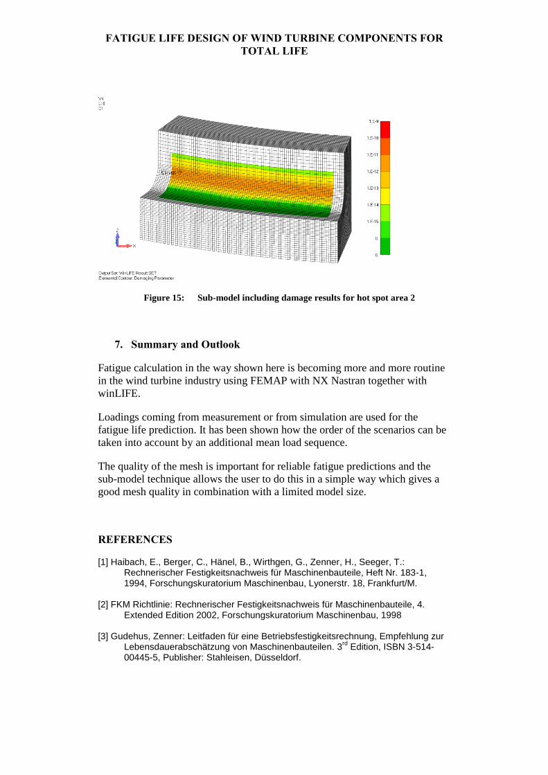
The sub-model for the two hot-spots is shown in figures 14 and 15.
It can be seen, that not only the result has changed but also the order of the
critical points.
Figure 14: Sub-model including damage results for hot spot area 1
FATIGUE LIFE DESIGN OF WIND TURBINE COMPONENTS FOR
TOTAL LIFE
Figure 15: Sub-model including damage results for hot spot area 2
7. Summary and Outlook
Fatigue calculation in the way shown here is becoming more and more routine
in the wind turbine industry using FEMAP with NX Nastran together with
winLIFE.
Loadings coming from measurement or from simulation are used for the
fatigue life prediction. It has been shown how the order of the scenarios can be
taken into account by an additional mean load sequence.
The quality of the mesh is important for reliable fatigue predictions and the
sub-model technique allows the user to do this in a simple way which gives a
good mesh quality in combination with a limited model size.
REFERENCES
[1] Haibach, E., Berger, C., Hänel, B., Wirthgen, G., Zenner, H., Seeger, T.: Rechnerischer Festigkeitsnachweis für Maschinenbauteile, Heft Nr. 183-1, 1994, Forschungskuratorium Maschinenbau, Lyonerstr. 18, Frankfurt/M.
[2] FKM Richtlinie: Rechnerischer Festigkeitsnachweis für Maschinenbauteile, 4.
Extended Edition 2002, Forschungskuratorium Maschinenbau, 1998 [3] Gudehus, Zenner: Leitfaden für eine Betriebsfestigkeitsrechnung, Empfehlung zur
Lebensdauerabschätzung von Maschinenbauteilen. 3rd
Edition, ISBN 3-514-00445-5, Publisher: Stahleisen, Düsseldorf.

FATIGUE LIFE DESIGN OF WIND TURBINE COMPONENTS FOR
TOTAL LIFE
[4] Guideline for the certification of wind turbines, Edition 2005, Germanischer Lloyd, [5] Hobbacher, A.: Recommendations for fatigue design of welded joints and
components, International Institute of welding, IIW document IIW-1823-07 December 2008
[6] Weber, E.; Häckh, J.: Willmerding, G.: Fatigue Life calculation using winLIFE.
NAFEMS conference Wiesbaden, 2010. [7] Artner, W.; Häckh, J; Willmerding, G.: Berechnung der Lebensdauer von
Windenergieanlagen unter Verwendung gemessener Lastdaten; VDI-Tagung Zuverlässigkeit von Windenergieanlagen, Bremerhaven, 2012
[8] Willmerding, G.; Häckh, J; Seifert, C.; Weber, E.; Radovcic, Y.: Fatigue Life Design for Wind Turbine Components using winLIFE, NAFEMS conference 2011, Boston