fatigue performance evaluation of forged versus …/media/files/autosteel/great designs in... ·...
TRANSCRIPT

w w w . a u t o s t e e l . o r g
Fatigue Performance Evaluation of Forged Versus Competing Process
Technologies Study
George F MochnalDirector of Research and Education
Forging Industry AssociationForging Industry Educational and Research Foundation

w w w . a u t o s t e e l . o r g
Forging Industry Educational and Research Foundation
Company Logo
Education1. To support programs at a number of universities where there is
exceptional interest in forging and substantial course enrichment in forging process and application.
2. To offer to selected universities instructional materials on forging for incorporation into metallurgy and materials courses.
Research and Development1. To sponsor research and development projects aimed at:
• Easing or solving technical problems facing the forging industry;
• Advancing technology in design, metallurgy, manufacturing and processing of forgings.

w w w . a u t o s t e e l . o r g
Joint Industry AllianceCompany Logo
Steel, Forging and Heat Treating Industry Pact
Heat Treating Society
JointIndustry Alliance
(JIA)
w w w . a u t o s t e e l . o r g
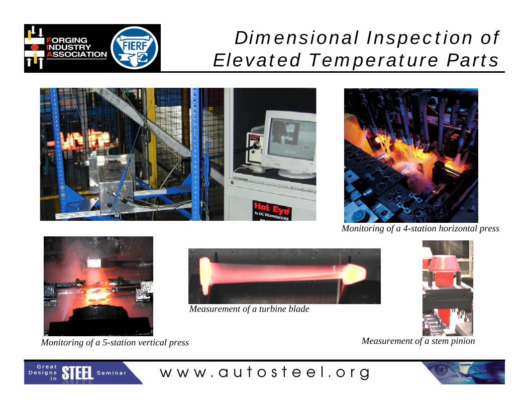
Dimensional Inspection of Elevated Temperature Parts
Company Logo
Measurement of a turbine blade
Monitoring of a 5-station vertical press Measurement of a stem pinion
Monitoring of a 4-station horizontal press

w w w . a u t o s t e e l . o r g
Study of Comparative PropertiesCompany Logo
Dr. Ali Fatemi and Research Assistant Mehrdad Zorouficonducted an experimental and analytical comparative study of forged steel, cast iron and cast aluminum steering knuckles at the University of Toledo.
This research was funded by Forging Industry Educational and Research Foundation (FIERF) in cooperation with the American Iron and Steel Institute (AISI)

w w w . a u t o s t e e l . o r g
Results of StudyCompany Logo
1. Yield strength of forged steel to be 140% higher than cast aluminum and 85% higher than cast iron;
2. Ductility of forged steel to be 270% higher than cast aluminum and 48% higher than cast iron;
3. Fatigue strength (at 106 cycles) of forged steel to be 190% higher than cast aluminum and 40% higher than cast iron;
4. Forged steel to be superior with respect to cyclic plastic deformation - a major concern for automotive suspension components;
5. Forged steel knuckle gives about 100 times longer fatigue life than cast aluminum knuckle at the same stress level.

w w w . a u t o s t e e l . o r g
Connecting Rod and Steering Knuckle Optimization Technologies
Adila Afzal, Pravardhan Shenoy, Mehrdad Zoroufiand
Ali Fatemi, ProfessorThe University of Toledo
Funded by:
and
w w w . a u t o s t e e l . o r g
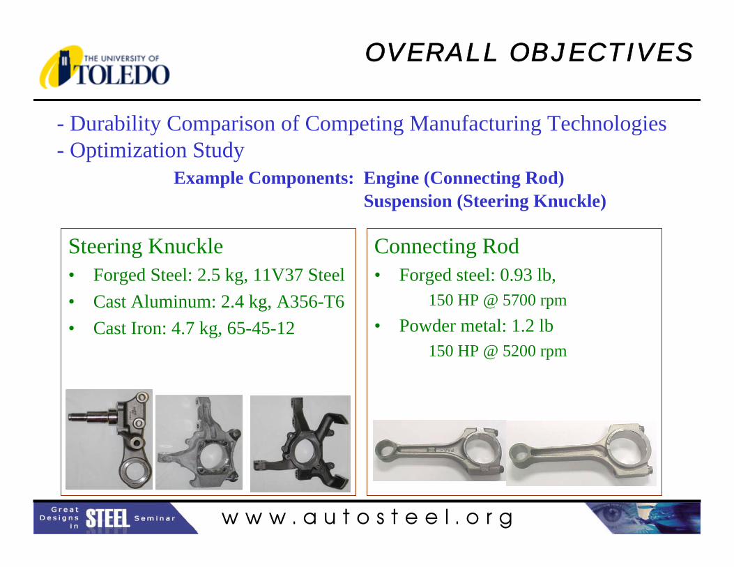
Steering Knuckle• Forged Steel: 2.5 kg, 11V37 Steel• Cast Aluminum: 2.4 kg, A356-T6• Cast Iron: 4.7 kg, 65-45-12
OVERALL OBJECTIVES
- Durability Comparison of Competing Manufacturing Technologies- Optimization Study
Example Components: Engine (Connecting Rod)Suspension (Steering Knuckle)
Connecting Rod• Forged steel: 0.93 lb,
150 HP @ 5700 rpm• Powder metal: 1.2 lb
150 HP @ 5200 rpm

w w w . a u t o s t e e l . o r g
DURABILITY COMPARISONSConnecting Rod: Specimen Tests
2.54
76
6.985
9.53
2.5
24.5R1
2.7
0100200300400500600700800900
1000
0.0% 0.5% 1.0% 1.5% 2.0%
True Strain (%)
Tru
e St
ress
(M
Pa) Forged Steel
Powder Metal
O Forged steelX Powder metal
1E+4 1E+5 1E+6 1E+7200
1000
1E+3
Tru
e St
ress
Am
plitu
de, Δσ/
2 (M
Pa)
Reversals to Failure, 2Nf
0.10%
1.00%
1E+3 1E+4 1E+5 1E+6 1E+7 1E+8Reversals to Failure, 2Nf
Tru
e St
rain
Am
plitu
de, Δε/
2, %
O Forged steelX Powder metal
1E+4 1E+5 1E+6 E+70.10%
1.00%
1E+3Reversals to Failure, 2Nf
1E+8
Tru
e St
rain
Am
plitu
de, Δε/
2, %
Tensile Tests
Fatigue Tests Fatigue Tests
w w w . a u t o s t e e l . o r g
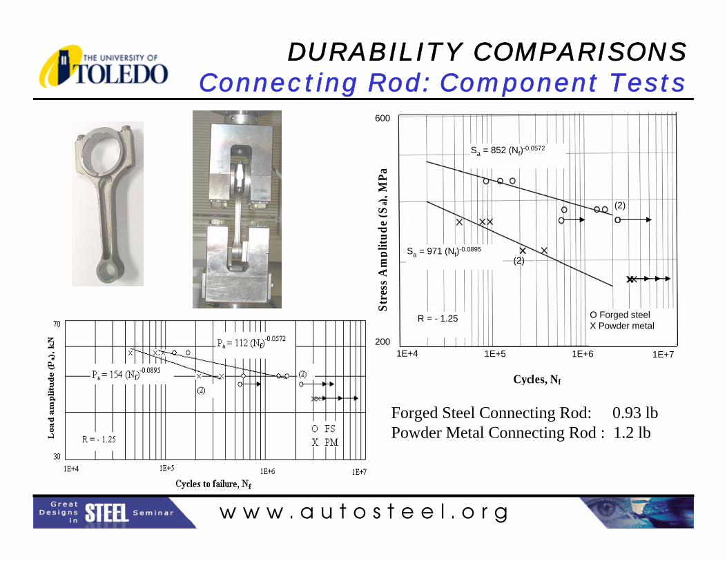
DURABILITY COMPARISONSConnecting Rod: Component Tests
Sa = 852 (Nf)-0.0572
Sa = 971 (Nf)-0.0895
O Forged steelX Powder metal
R = - 1.25
(2)
1E+4
(2)
1E+5 1E+6 1E+7200
600
Cycles, NfSt
ress
Am
plitu
de (S
a ), M
Pa (M
Pa)
Forged Steel Connecting Rod: 0.93 lbPowder Metal Connecting Rod : 1.2 lb

w w w . a u t o s t e e l . o r g
DURABILITY COMPARISONSSteering Knuckle: Specimen Tests
2.54
76
6.985
9.53
2.5
24.5
R12.
7
Tensile Tests
0
100
200
300
400
500
600
700
800
900
0.0% 0.2% 0.4% 0.6% 0.8% 1.0%
True Strain (%)
True
Stre
ss (
MP
a)
Tensile Tests
Cast Iron
Forged Steel
Cast Aluminum

w w w . a u t o s t e e l . o r g
DURABILITY COMPARISONSSteering Knuckle: Specimen Tests
0.001%
0.010%
0.100%
1.000%
1E+2 1E+3 1E+4 1E+5 1E+6
Reversals to Failure, 2Nf
True
Pla
stic
Strai
n Am
plitu
de (%
)
Forged Steel 11V37Cast Iron 65-45-12Cast Aluminum A356-T6
0.10%
1.00%
1E+2 1E+3 1E+4 1E+5 1E+6 1E+7 1E+8
Reversals to Failure, 2Nf
True
Str
ain
Am
plitu
de (%
)
Forged Steel 11V37Cast Aluminum A356Cast Iron 65-45-12
0.1
1.0
10.0
1E+2 1E+3 1E+4 1E+5 1E+6 1E+7 1E+8
Reversals to Failure, 2Nf
ε aσ a
(MPa
)
Forged Steel 11V37Cast Iron 65-45-12Cast Aluminum A356-T6

w w w . a u t o s t e e l . o r g
DURABILITY COMPARISONSSteering Knuckle: Component Tests
0.5
1.5
0 0.2 0.4 0.6 0.8 1
Normalized Number of Cycles, N/Nf
Dis
plac
emen
t Am
plitu
de (m
m) Forged Steel Knuckle
Cast Aluminum Knuckle
crack nucleates

w w w . a u t o s t e e l . o r g
REFERENCE PUBLICATIONSSteering Knuckle
• “Fatigue Life Comparison of Competing Manufacturing Processes: A Study of Steering Knuckle”, M. Zoroufi and A. Fatemi, SAE Technical paper 2004-01-0628, SAE World Congress 2004, Detroit, MI, March 2004.
• “Fatigue Performance Evaluation of Forged vs. Competing Process Technologies: A Comparative Study”, A. Fatemi and M. Zoroufi, 24th Forging Industry Technical Conference, Cleveland, OH, October 2002.
• “Durability Comparison and Life Predictions of Competing Manufacturing Processes: An Experimental Study of Steering Knuckle”, M. Zoroufi and A. Fatemi, 25th Forging Industry Technical Conference, Detroit, MI, April 2004.
• “A Comparative Study of Forged Steel 11V37, Cast Aluminum A356-T6, and Cast Iron 65-45-12; Monotonic Properties, Cyclic Deformation, and Fatigue Behavior”, M. Zoroufi and A. Fatemi, Technical Report to FIERF and AISI (available through www.forging.org), March 2003.
• “Fatigue Performance Evaluation of Forged versus Competing Manufacturing Process Technologies: A Comparative Analytical andExperimental Study”, M. Zoroufi and A. Fatemi, Technical Report to FIERF and AISI (available through www.forging.org), September 2004.

w w w . a u t o s t e e l . o r g
REFERENCE PUBLICATIONSConnecting Rod
• “A Comparative Study of Fatigue Behavior and Life Predictions of Forged Steel and PM Connecting Rods”, A. Afzal and A. Fatemi, SAE Technical paper 2004-01-1529, SAE World Congress 2004, Detroit, MI, March 2004.
• “Connecting Rod Optimization for Weight and Cost Reduction”, P. Shenoyand A. Fatemi, SAE Technical paper 2005-01-0987, SAE World Congress 2005, Detroit, MI, April 2005.
• “Fatigue Behavior and Life Predictions of Forged Steel and Powder Metal Connecting Rods”, A. Afzal and A. Fatemi, Technical Report to AISI(available through www.autosteel.org), May 2004.
• “Dynamic Load Analysis and Optimization of Connecting Rod ”, P. Shenoyand A. Fatemi, Technical Report to AISI (available through www.autosteel.org), May 2004.

w w w . a u t o s t e e l . o r g
OPTIMIZATION STUDY
Forged Steel Connecting Rod• Dynamic load analysis• FE modeling (elastic)• Stress analysis• Optimization
– Geometry constraints– Manufacturing processes– Material alternatives– Cost
Forged Steel Steering Knuckle• FE modeling (inelastic)• Stress analysis• Optimization
– Geometry constraints– Manufacturing processes– Material alternatives– Cost

w w w . a u t o s t e e l . o r g
OPTIMIZATION STUDYSteering Knuckle FE Model
• Primary loading is bending• Spindle 2nd step fillet is the critical location• Local yielding occurs• Material model
– Elastic-plastic– Cyclic deformation properties

w w w . a u t o s t e e l . o r g
DESIGN VARIABLES
• Material
• Manufacturing process– Forging steps– Machining– Grinding
• Part processing– Heat treatment– Surface treatment– Inducing compressive
residual stress– Fillet rolling– etc.
CONSTRAINTS
• Equivalent or longer life• Geometry:
– Strut mounting bolt-hole size and location
– Suspension connection bolt-hole size and location
– Spindle diameters and length
OBJECTIVE
Minimize Weight and Cost
OPTIMIZATION STUDY Steering Knuckle

w w w . a u t o s t e e l . o r g
OPTIMIZATION STUDYSteering Knuckle Manufacturing Process
FORGING MACHINING
RAW MATERIAL INPUT
RAW MATERIAL INSPECTION
CUT TO SIZE OF PART
INDUCTION OR FURNACE HEATING
IMPRESSION-DIE FORGING
TRIMMING
INSPECTION & DIMENSIONAL CHECK
TURN SPINDLE
DIMENSIONAL CHECK
MILL STRUT JOINT HOLES
CLEANING, FINAL INSPECTION, SHIPPINGSHOT CLEANING
MAKE STRUT JOINT CHAMFER
MAKE HUB MOUNTING HOLE CHAMFER
MILL TENSION STRUT STEPS
DRILL HUB MOUNTING HOLES
CUT SPINDLE THREADS
CUT HUB MOUNTING HOLE THREADS
MAKE LATERAL LINK HOLE
SPINDLE DIAMETER AND THREADS INSPECION
SAMPLE EDDY CURRENT INSPECTION

w w w . a u t o s t e e l . o r g
FORGRED STEEL STEERING KNUCKLE OPTIMIZATION ALTERNATIVES
NO CHANGE IN ATTACHMENT
GEOMETRY
LIMITED CHANGE IN ATTACHMENT
GEOMETRY
FOCUS:Minimize spindle’s mass with limited attachment changesModify manufacturing process
FOCUS:Minimize mass while maintaining the overall shape and attachment dimensionsModify manufacturing process
STAGE I
STAGE II
OPTIMIZATION STUDY Steering Knuckle

w w w . a u t o s t e e l . o r g
Stress distribution under primary loading at the vicinity of top strut attachment
OPTIMIZATION STUDY Steering Knuckle: STAGE I
Higher stress in the optimized area, but still lower than the critical location

w w w . a u t o s t e e l . o r g
Redesigned spindle
Tapered-bore bearing
Stress contour
Final design
OPTIMIZATION STUDY Steering Knuckle: STAGE II

w w w . a u t o s t e e l . o r g
OPTIMIZATION STUDYSteering Knuckle: Process Modifications and
Alternative Materials
Material Alternative Criteria• Superior mechanical
properties & fatigue strength
• Equivalent or better machinability
• Microalloyed• Cost?
Material AlternativesSAE 15V24SAE 15R30VSAE 1522 MoVTiSAE 1522 MoVTiSSAE 1534 MoVTiSAE 1534 MoVTiSi
Very limited weight saving is achieved, due to geometrical constraints
Process ModificationsPrecision forging vs. conventional forgingWarm forging vs. hot forgingReduction of machining steps
(pierced mounting holes versus machined)
4 HUB MOUNTING
HOLESSTRUT MOUNTING HOLES
Improving Fatigue PerformanceSurface hardeningSurface rollingCost?

w w w . a u t o s t e e l . o r g
OPTIMIZATION STUDYSteering Knuckle: Improving Fatigue Performance
Example ofSurface Hardening
Cost?
Example of Surface Rolling
Cost?
Effect of induction hardening on truck stub axle and depth of induction hardened zone (Schijve, 2001)
Effect of rolling of the notch root on rotating bending fatigue of 37CrS4 steel (Kloos et al., 1987).

w w w . a u t o s t e e l . o r g
5% + material saving
At least 12%Spindle redesignedStage II
5% + material saving
At least 9%Strut holes pierced
Hub mounting bolt holes pierced
Material removed from bodyHub mounting thickness optimizedLateral link joint thickness optimized
Stage I
Cost Reduction
Weight Reduction
Process ChangeGeometry Change
OPTIMIZATION STUDYSteering Knuckle: Summary
Limitations• Many attachment compatibility constraints
• More comprehensive change on constraints can result in major design alterations in suspension system
• Significant thickness reduction in this relatively small part results in distortion of the component during forging
• Emphasis on optimization process

w w w . a u t o s t e e l . o r g
OPTIMIZATION STUDYConnecting Rod
Forged Steel Connecting Rod• Dynamic load analysis• Stress analysis (elastic FEA)• Optimization
– Geometry constraints– Manufacturing processes– Material alternatives– Cost
0
5
10
15
20
25
30
35
40
0 100 200 300 400 500 600 700Crank Angle - degree
Cyl
inde
r Pre
ssur
e - b
ar Compressive: Max gas load
-250
-200
-150
-100
-50
0
50
100
150
200
250
Crank Angle - deg-150000
-100000
-50000
0
50000
100000
150000
2
Angular Velocity
0 360 720
Angular AccelerationTensile: Inertia load at 360o
Design loads:• Compressive: Max gas load• Tensile: Inertia load at 360o
at max. speed

w w w . a u t o s t e e l . o r g
- Forces at the Crank and Pin Ends at Max. Speed(5700 RPM)
- Max Fx at each end is different.- Fy is significant (i.e. bending).
Fy
Fx
Crank End
-2.0E+04
-1.5E+04
-1.0E+04
-5.0E+03
0.0E+00
5.0E+03
1.0E+04
1.5E+04
2.0E+04
0 200 400 600
Crank Angle- deg
Forc
e-N
FxFy
Piston Pin End
-1.5E+04
-1.0E+04
-5.0E+03
0.0E+00
5.0E+03
1.0E+04
1.5E+04
0 90 180 270 360 450 540 630 720
Crank Angle- deg
Forc
e- N
FxFy
OPTIMIZATION STUDYConnecting Rod: Load Analysis

w w w . a u t o s t e e l . o r g
OPTIMIZATION STUDYConnecting Rod: Dynamic Analysis
-150.0
-100.0
-50.0
0.0
50.0
100.0
0 100 200 300 400 500 600 700
Crank Angle- deg
Stre
ss -
MPa
8-XX9-XX8-von Mises9-von Mises
1
2
3
4
56
7
8
9
10
11
-100
-50
0
50
100
150
200
0 100 200 300 400 500 600 700
Crank Angle- deg
Stre
ss -
MPa
10-XX10-YY10-XY11-XX11-YY11-XY10-von Mises11-von Mises
• Multiaxial stress state at some locations
• R ratio varies along rod.• Bending stress is significant

w w w . a u t o s t e e l . o r g
OPTIMIZATION STUDYConnecting Rod: Static vs Dynamic Analysis
1
2
3
4
56
7
8
9
10
11
0
50
100
150
200
250
300
350
400
450
1 2 3 4 5 6 7 8 9 10 11Location on the Connecting Rod
Equi
vale
nt S
tress
Am
plitu
de -
MPa
StaticQuasi-dynamic

w w w . a u t o s t e e l . o r g
OPTIMIZATION STUDYConnecting Rod
Objective: Optimize weight and cost.– Weight: Optimize geometry– Cost: Use C70 “crackable” steel.
Expected cost reduction 25% (Repgen, 1998).
Focus mainly on the shank region.
Constraints: Protect against:• Maximum Tensile Load: Yielding in tension• Maximum Compressive Load: Yielding in compression or buckling• Maximum Load Amplitude: Fatigue failure• Maximum Bending Stress: Deflection in bending
• Side constraints (Dimensions compatible with existing geometry)
• Manufacturing constraints (Forging feasibility: i.e. distortion, draft angle)

w w w . a u t o s t e e l . o r g
Optimized connecting rod
Existing connecting rod
Existing Connecting Rod
Optimized Connecting Rod
OPTIMIZATION STUDYConnecting Rod
• The optimized geometry is 10% lighter than the original in spite of lower strength of C-70 steel.
• With higher strength facture crackable materials such as micro-alloyed steels, the weight can be further reduced.
• Weight reduction in the shank region is limited by manufacturing constraints (i.e. forging distortion).

w w w . a u t o s t e e l . o r g
OPTIMIZATION STUDYConnecting Rod
Manufacturing steps eliminated by using C-70 crackable steel:
• The need to separately forge the cap and the body of the connecting rod • Heat treatment• Machining of the mating faces of the crank end• Drilling for the sleeve
Cost Savings by using C-70 crackable steel
• Machining cost comprises 62% of the total cost for the conventional forged steel connecting rod (Clark et al., 1989)
• Machining cost reduction from utilization of the fracture splitting process, results in 23% total cost savings (Clark et al., 1989)
• “The development of fracture splitting the connecting rods achieves a total cost reduction up to 25% compared to conventionally designed connecting rods and is widely accepted in Europe” (Repgen, 1998, SAE Paper 980882 )

w w w . a u t o s t e e l . o r g
CONCLUSIONSConnecting Rod
• Tensile and fatigue strengths of forged steel were higher than those for the powder metal, based on specimen and component fatigue tests.
• There is considerable difference in the structural behavior of the connecting rod between static loading and dynamic loading (i.e. operating condition).
• The optimized geometry is 10% lighter than the existing rod. With higher strength crackable materials the weight can be further reduced.
• Reduction in machining operations achieved by using the fracturesplitting process reduces the production cost by about 25%.
• The unique fracture surface from the fracture splitting process prevents the rod and the cap from relative movement. This results in an increase in the stiffness and reduction of stresses at critical locations.

w w w . a u t o s t e e l . o r g
CONCLUSIONSSteering Knuckle
• Forged steel is considerably stronger and more ductile than castaluminum and cast iron. Fatigue strength of forged steel is also considerably higher than cast aluminum and cast iron.
• The material undergoes plastic deformation at stress concentrations during overload cycles. The use of linear elastic FEA is not sufficient for reliable life predictions and optimization.
• Overall weight reduction of at least 12% and cost reduction of at least 5% are estimated for the forged steel steering knuckle.
• Much higher potential for weight and cost savings exists for larger components and, if a more comprehensive change to the suspensionsystem can be made.