fault tolerance of the application manager in vigne
TRANSCRIPT

Fault Tolerance of the Application Manager in
Vigne
Rajib Kumar Nath1,2
1IRISA/Paris Project-Team, 2University of Tennessee, [email protected]
1 Introduction
Failure is a common phenomenon in distributed systems. As a system gets largerand complex, the numbers, sources and types of errors increase proportionately.To implement a system that works properly despite failures has been a majorconcern in distributed system research community for the past few decades.Researchers have been trying to enhance fault tolerance in every sector of com-puting such as web servers, storage, microprocessor, communication channel,application components etc. But ensuring fault tolerance in a large system likegrid has been a very challenging and troublesome job. Grid is a collection ofcomputing resources located in different administrative domain. Because of thislarge volume, it’s not easy to manage grid. The grid middleware was introducedto fulfill this need. Usually a user submits a job through grid middleware andgets the result back after the computation is over. Throughout the life time ofthe job, a grid middleware service component manages the job on behalf of theclient. In the grid middleware Vigne [39, 32], developed by Paris project teamin IRISA, Application Manager (AM) is the service component that supervisesany application. It is the critical component of the system. That’s why we wantit to keep running despite any failures or reconfiguration that can occur in thegrid. The goal of our work is to find sollution to increase the availability of AMin Vigne.
This report is organized as follows. Section 2 gives a short description ofVigne and presents the problem informally. Section 3 recognizes critical issues ina fault tolerant system. Then we describe the existing fault tolerance techniquesand compared them in section 4 to select a suitable technique for replicatingAM. Section 5 and section 6 make the necessary specifications to integratethe selected technique in Vigne. Section 7 addresses crucial issues regardingreconfiguration in highly dynamic environment. Related works are presented insection 8. Finally we present the conclusion and future work in section 9.
1

2 Context
In this section we give a short description of Vigne, its underlying peer to peernetwork and some of its service components. We also present our problem offault tolerance of the AM and address the necessity of replicating other services.At the end, we present our assumption about the system.
2.1 Vigne and it’s Three Basic Principles:
Vigne is a grid middleware that have been developed in the first place to makeuse of various types of numerous computing resources located in different geo-graphical locations and to serve the scientific computing community. Any sys-tem (e.g. cluster, personal computer) can connect to or disconnect from Vigneat any time and thereby used for computing jobs submitted by client. As Vignepossesses no control over any of these resources, failures and node arrivals arevery frequent in the system. Any resource can be manually restarted or stoppedby the owner, or there may be failures. This dynamism has put Vigne in a po-sition of enhancing fault tolerance of an ongoing computation as well as of itsservice components.
Because of heterogeneous resource types and dynamic environment, threebasic principles have been maintained during the design and implementationphase of Vigne: Single System Image, Self Healing and Self Organization [39].
• Single System Image: Users are provided with a simple abstraction thathides the physical distribution and types of resources.
• Self Healing: In case of node addition, removal or failures, Vigne auto-matically reconfigures while preserving transparency with users. It alsoprovides transparent and generic fault tolerance for computations.
• Self Organization: The owner of a resource has to maintain the localsetting of his resource. Once the resource has been integrated to Vigne,the responsibility of efficient use of the resource is delegated to Vigne.
2.2 Network and Service Components of Vigne:
The underlying network of Vigne is a peer to peer network [2, 29]. The choiceof peer to peer network naturally follows from the last two basic principles men-tioned in section 2.1. Vigne is implemented on top of Pastry [29, 34] structuredoverlay [17] with maintenance algorithm of BAMBOO [2]. Any node can jointhe overlay of Vigne by contacting a node that has already been included inthe network of Vigne. Meanwhile the principle of Single System Image hasmotivated Vigne to include high level distributed services such as applicationscheduling, persistent data management, volatile data management [33] and lowlevel services such as resource access control and membership [17]. Among allthese services, the two most important services are Application Manager andResource Allocator which are built on a peer to peer infrastructure. They aredescribed in next two subsections.

Figure 1: Client-Application Manager Interation in Vigne
2.3 Application Manager in Vigne
AM is a dedicated agent that supervises an application throughout its lifetime.Whenever a client desires to submit a job, he or she contacts a node thatis already part of the Vigne peer to peer overlay and thereby handovers thejob description file. The Application Scheduling Service of the contacted nodechooses an Application Manager Key (AM-Key) randomly. Then an AM iscreated in a node whose id in the p2p overlay is the closest to the AM-Key amongall the nodes’ id in Vigne on that particular moment and the client is informedwith the AM-Key. In future the client can make any query or modification of theapplication using this AM-key because any application related message is routedto the right AM in the structured overlay. Since the submission of the job bythe client, AM acts on behalf of the client to run the computation successfullydespite any change in the peer to peer overlay. All resource necessary for thecomputation is provided by the AM by contacting the Resource Discoverer.The fault tolerance of the application process is also provided by the AM [32,17]. The current picture of AM and client interaction in Vigne is shown inFigure 1(Here AP stands for Application Process).
Unfortunately its way too likely that host node of AM will fail. So it ishighly important for Vigne to increase the availability of AM. Otherwise in caseof failure of the AM’s host node, the Application will be running without anycoordination. It may stop on the halfway waiting for the failed AM’s signal andthe client will never get the result or status of the submitted job. As a resultallocated resources might not be freed. The goal of our work is to tolerate suchfailure. With this goal in mind, we have evaluated the existing fault tolerancetechniques and chosen the best suitable one. Then we have made specificationsand design choices to integrate this feature in Vigne.
2.4 Resource Allocator in Vigne
The Resource Allocator (RA) is the component that searches, selects and allo-cates most suitable resources for an application according to the job specificationgiven by the client during the job submission phase. The job specification in-

cludes processor architecture, number of processors, operating system, free diskspace, scheduler etc. The resource discovery is performed using unstructuredpeer to peer overlay as some of these job requirement might not be a scalarcriteria (e.g. memory, free disk space). Currently there are three protocols inVigne for resource discovery: (a) Basic Flooding, (b) Random Walk, and (c)Reinforcement Learning.
The placement or activity of the RA in Vigne is pretty analogous to AM.It is application specific and RA resides on the same physical node as AMis. The failure or node arrivals in the Pastry DHT † namespace affect RAas the same way it affects AM. Even if we replicate the AM, we will fail tomaintain consistency. In case of a failure of RA’s host node, all the applicationspecific information will be gone. A neighboring node will start acting as RAfor the corresponding application and the new RA will have no way to figureout whether the upcoming request is a duplicate request that has already beenserved or it’s a new request. Hence we need to replicate the RA as well. Thesame concern applies to Application Monitor. For this study, we assume thatRA(Resource Allocator) and Application Monitor remains available all the time.We only focus on the failure of the AM(Application Manager).
2.5 Assumption about the System
The correctness or validity of any distributed algorithm or system lies on someassumption. Our assumptions are as follows:
• We will consider only Fail-stop failures. Byzantine failures [23] are nottaken into account as they can be handled using cryptographic algorithmand error check-sum with some majority rules.
• The underlying communication channel is unreliable and non-FIFO.
• We didn’t assume any distribution about the node arrival or failure rate inthe peer to peer overlay. Any node at any place in Pastry DHT namespacecan fail or join at any moment.
• The other system service components (e.g. Resource Allocator, Applica-tion Monitor) remains available all the time.
3 Critical Issues in a Fault Tolerant System
The following issues regarding fault tolerance need to be considered during thedesign phase of a fault tolerant AM in Vigne:
†DHT stands for Distributed Hash Table and it performs the purpose of a hash function.Someone can store a < key, value > pair and lookup the value later if he has the key. Thename DHT comes from the property that staorage and lookups in the DHT is distributedamong multiple nodes. This inherent property has made DHT popular in fault tolerant peerto peer computing.

Figure 2: Fault Tolerance Hieararchy
• Reliability: Vigne should avoid single point of failure, otherwise therewould be no way to recover. It should also avoid single point of repair foranalogous reason.
• Scalability: The system should be decentralized so that huge amountof client requests are evenly distributed among available resources. AsVigne should be capable of managing thousands of Applications on nu-merous grid nodes, any centralized solution will put Vigne’s performancein jeopardy.
• Transparency: The property of Single System Image in Vigne shouldbe preserved. Any replication should remain transparent to ApplicationProcess and specifically to clients.
• Consistency: The system should always compute and deliver consistentresult even if there is a failure.
4 Existing Fault Tolerance Techniques
In this section, we describe and evaluate existing fault tolerance techniques tochoose the best suitable one for replicating AM in Vigne. There are severaltechniques to achieve a fault tolerant system in literature. The common hierar-chy of fault tolerance techniques is show in Figure 2. As we can see there aretwo major trends: Flat and Hierarchical depending on the presence of hierarchyin the fault tolerant mechanism. The characteristics of different techniques aredescribed below.

Figure 3: Active/Standby with Shared Storage
4.1 Active/(Cold)Standby Replication with Shared Stor-age
The active service component stores its current state in a stable storage infre-quently while serving clients’ request. An analogous standby entity monitorsthe health of the original service component through heart beat mechanism. Ifthe standby monitoring component suspects the active component as faulty, itrestores the last saved state from the stable storage and takes the role of theactive component (Figure 3).
4.1.1 Benefits
• Low Redundancy: It needs less computing resources than most of thereplication techniques. Besides there is no software redundancy as thestandby component doesn’t do any computing other than monitoring theactive component.
4.1.2 Drawbacks
• Single Point of Failure: It uses a shared storage to store the state ofthe service. But stable storage may not always be available. Eventhoughit’s available somewherer in the grid, the physical node that is holding theAM may not have any stable storage. It’s true that with the help of RA,we can resolve the problem. But the owner of the stable storage may takeit out of grid any time he or she wants. Hence technically, it will turn outas a single point of failure.
• Loss of State:As the service has to roll back, it will lose states betweenthe last checkpoint time and the time of failure event.
• No Seperation of Responsibility, Less Flexibility: If we are usingcheckpointing for fault tolerance of AM then it will be efficient if thecheckpointing of application process and AM are not decoupled. Hencewe will lose some flexibility.
• Parametric Sollution: The efficiency of the system will depend on thefrequency of the checkpointing. If we take the checkpoint more frequentlythen it will be inefficient and the processes will do more checkpointingthan the original job that they have been assigned for, but it will increaseavailability. If we do checkpointing less frequently then we run the riskof losing massive amount of computation in case there is a failure be-tween last checkpointing and just before the next checkpointing. Hencethe checkpointing period is a critical parameter for the system and it willbe hard to calibrate such parameter because of the dynamic environmentof grid.
• Low Performance and Implementation Hardship: The main bottle-neck in checkpointing algorithm lies in the time required to write states onthe stable storage. To take a checkpoint, all the processes have to agree onsome snap-shot period according to some global snapshot algorithm (e.g.Chandy-Lamport). This will incorporate some communication overheadand hamper the performance of the applications and networks.
It will not be easy to decide the checkpointing time. In Vigne, if wethink about the application submission period, we will find that there aretwo different times when we might do the checkpointing: after resourcediscovery phase is over or after sending back the application key to theclient. Each of the choices has its own drawbacks. Whatever we choosehere, we have to take care of these cases with logical checking in therelated code. On the other hand, if we want the checkpointing in everysuch case, it will increase the number of checkpoints. As the RA is involvedthroughout the life time of an application, many such cases will arise. Thusit will lead us to implementation hardship(e.g. changing the existing code)as well as to low performance.
• Low Availability: A substantial startup time is required for the standbyto take over the failed one and update it’s states. In Vigne, the applicationprocesses may have to rollback and restart from the last checkpoint. Hencethe service will be unavailable for certain amount of time.
• Lack of Transparency: A separate entity is required to detect the failureof the active component. Usually in the Active/ (Cold) Standby system,the standby component stays idle and keeps checking the health of theactive component through heart beat mechanism. If the standby entityisn’t replicated itself, it will be a single point of failure. If we want totolerate n failures at a time, we need n standby components waiting in achain fashion. First standby will monitor the active component. Secondstandby will monitor the first standby and so on. But n such failurescan occur in such a pattern that the system might be unavailable for asubstantial amount of time (e.g. n * MTTR, here MTTR is mean timeto recover). In Vigne, if a client comes by this time with a query orjob modification request, he will not be answered as there is no activeAM. The client might assume that the application manager doesn’t exist.
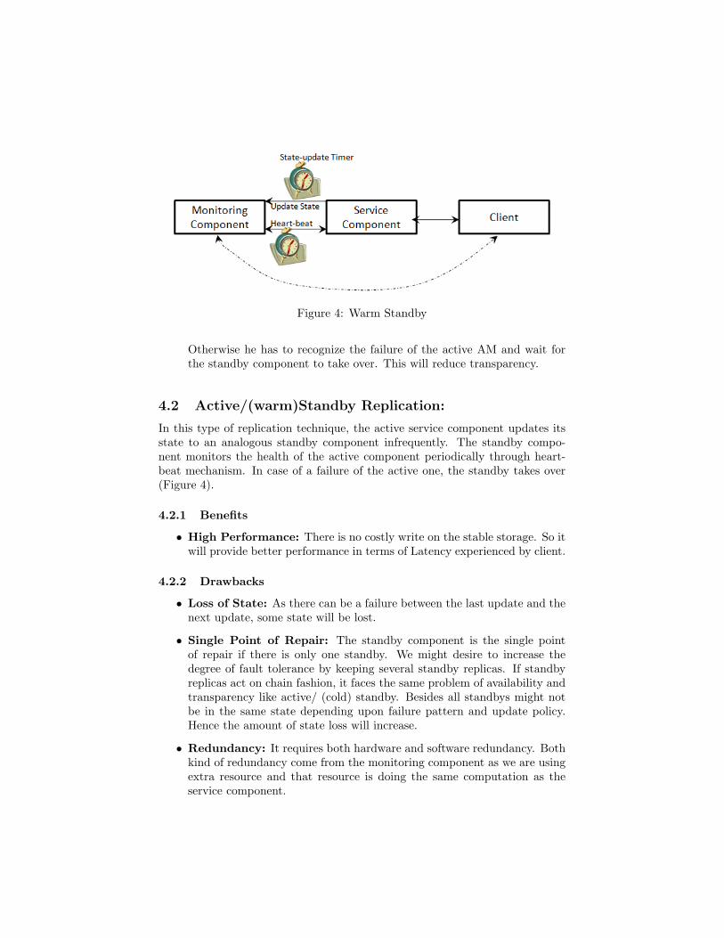
Figure 4: Warm Standby
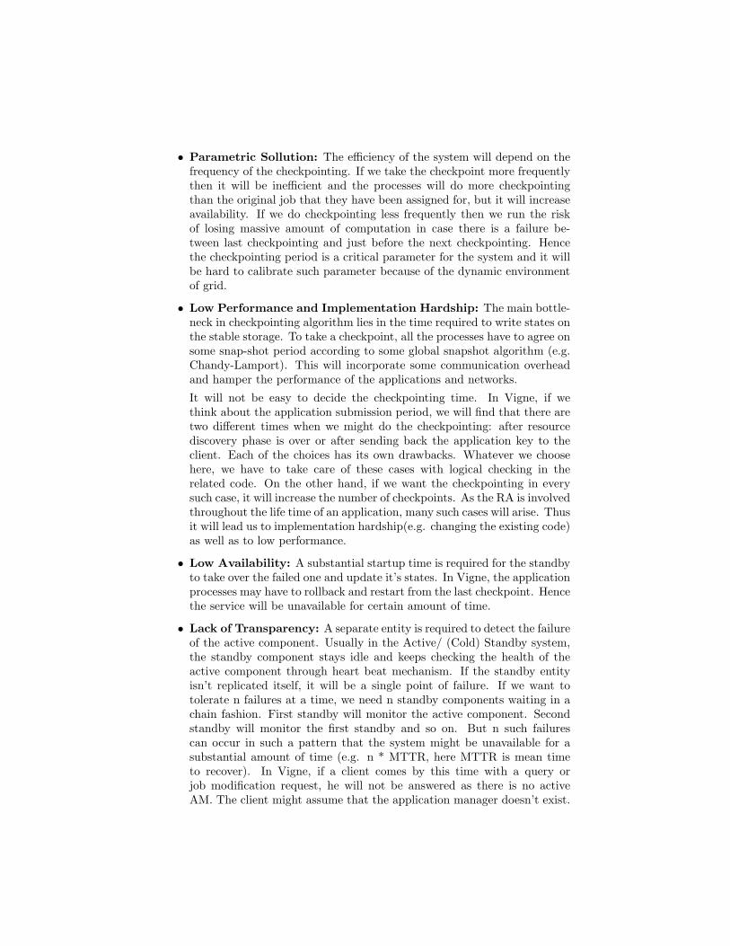
Otherwise he has to recognize the failure of the active AM and wait forthe standby component to take over. This will reduce transparency.
4.2 Active/(warm)Standby Replication:
In this type of replication technique, the active service component updates itsstate to an analogous standby component infrequently. The standby compo-nent monitors the health of the active component periodically through heart-beat mechanism. In case of a failure of the active one, the standby takes over(Figure 4).
4.2.1 Benefits
• High Performance: There is no costly write on the stable storage. So itwill provide better performance in terms of Latency experienced by client.
4.2.2 Drawbacks
• Loss of State: As there can be a failure between the last update and thenext update, some state will be lost.
• Single Point of Repair: The standby component is the single pointof repair if there is only one standby. We might desire to increase thedegree of fault tolerance by keeping several standby replicas. If standbyreplicas act on chain fashion, it faces the same problem of availability andtransparency like active/ (cold) standby. Besides all standbys might notbe in the same state depending upon failure pattern and update policy.Hence the amount of state loss will increase.
• Redundancy: It requires both hardware and software redundancy. Bothkind of redundancy come from the monitoring component as we are usingextra resource and that resource is doing the same computation as theservice component.
Figure 5: Active/(Hot) Standby Replication with Primary Backup
4.3 Manual Masking:
Manual masking requires human action to detect the failure and replace thefailed component with a good one. We can discard this from our poll of faulttolerance techniques because it will compromise the self healing property ofVigne.
4.4 Active/(Hot)Standby Replication with Primary Backup
The component to be replicated is called the primary. Primary is the only onethat communicates with outer worlds (client or Application Processes). Oneor more standby components are maintained. The standby replicas are alwayskept up-to-date with the current state of the primary replica so that in case ofa failure of the primary, a standby replica can take over automatically from thelast consistent state without any state loss (Figure 5).
4.4.1 Benefits
• No State Loss: As the primary and standby replicas follow same se-quence of states, no state is lost.
• Easy Implementation: It’s easy to implement from the programmerspoint of view given that there is a reliable failure detector. If there is nonethen it’s hard to implement in asynchronous system. This shortcomingcan be overcomed by primitives provided by View-Synchronous paradigm.
• Seperation of responsibility: In Vigne, we can easily separate thefault tolerance of Application Process and AM if we use this technique.Both of them can be handled separately with different policies. If bothresponsibilities are decoupled then the policy of fault tolerance of an ap-plication can be specified by the client before the start of the applicationdepending upon some metrics (e.g. importance of the application, prior-ity of the clients, critical characteristics or the available resources of the
system). If checkpointing is selected for the fault tolerance of applicationthen the interval between two checkpoints can be varied dynamically de-pending upon the failure rates in DHT namespace. On the other hand ifthe Active/(hot)Standby replication mechanism is chosen for ApplicationProcesses fault tolerance, then the replication policy and degree can beadjusted runtime. This will enhance the self healing property of Vigne.
4.4.2 Drawbacks
• Low Scalability: The primary replica will always be a bottleneck as heis the only one to receive or send messages from or to outer worlds and totake care of the state commit among the replicas. Hence a distant clientrelative to primary replica will experience a high response time.
• Lack of Transparency: If a standby replica fail-stops then it remainstransparent to the client. But the failure of the primary replica maynot remain transparent to the client anymore. In Vigne, the ApplicationProcess or client has to resend some of the messages in case of primaryAM’s failure.
• Low Availability, High Latency: In case of failure of the primary, ittakes a substantial amount of time for a standby to take over. So for awhile the service remains unavailable. In Vigne, this will lead to increasedlatency experienced by the client.
More precisely it depends on group membership for keeping consistentstate among the replicas. When the primary replica fails, the group needsto be adjusted and a group communication is started to select the newprimary dynamically. This dynamic group management introduces sub-stantial overhead.
4.5 Symmetric Active/Active Replication
In case of symmetric active/active replication, two or more analogous servicecomponents send or receive messages to or from clients or Application Processesby maintaining same sequence of global states. They use advanced state commitprotocol to keep the state consistent in every replicas. A common architectureof symmetric active/active replication is given in Figure 6. This figure is takenand modified from Engelmann et al.
4.5.1 Benefits
• No Single Point of Failure or Repair: There is no single point offailure which is the most desirable property of a fault tolerant system. Aslong as majority of replicas are non faulty, the system will go on withoutany interruption and make any necessary reconfiguration. Hence therewill be no single point of repair.
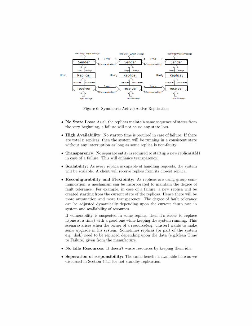
Figure 6: Symmetric Active/Active Replication
• No State Loss: As all the replicas maintain same sequence of states fromthe very beginning, a failure will not cause any state loss.
• High Availability: No startup time is required in case of failure. If thereare total n replicas, then the system will be running in a consistent statewithout any interruption as long as some replica is non-faulty.
• Transparency: No separate entity is required to startup a new replica(AM)in case of a failure. This will enhance transparency.
• Scalability: As every replica is capable of handling requests, the systemwill be scalable. A client will receive replies from its closest replica.
• Reconfigurability and Flexibility: As replicas are using group com-munication, a mechanism can be incorporated to maintain the degree offault tolerance. For example, in case of a failure, a new replica will becreated starting from the current state of the replicas. Hence there will bemore automation and more transparency. The degree of fault tolerancecan be adjusted dynamically depending upon the current churn rate insystem and availability of resources.
If vulnerability is suspected in some replica, then it’s easier to replaceit(one at a time) with a good one while keeping the system running. Thisscenario arises when the owner of a resource(e.g. cluster) wants to makesome upgrade in his system. Sometimes replicas (or part of the systeme.g. disk) need to be replaced depending upon the data (e.g.Mean Timeto Failure) given from the manufacture.
• No Idle Resources: It doesn’t waste resources by keeping them idle.
• Seperation of responsibility: The same benefit is available here as wediscussed in Section 4.4.1 for hot standby replication.
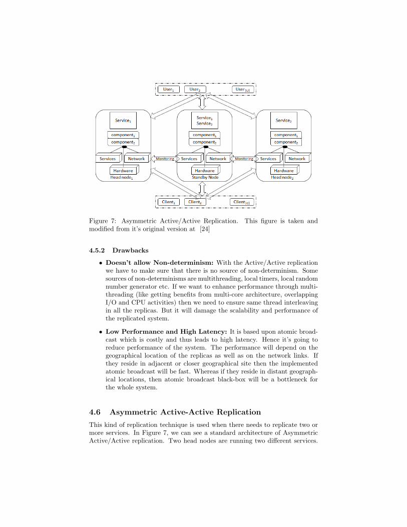
Figure 7: Asymmetric Active/Active Replication. This figure is taken andmodified from it’s original version at [24]
4.5.2 Drawbacks
• Doesn’t allow Non-determinism: With the Active/Active replicationwe have to make sure that there is no source of non-determinism. Somesources of non-determinisms are multithreading, local timers, local randomnumber generator etc. If we want to enhance performance through multi-threading (like getting benefits from multi-core architecture, overlappingI/O and CPU activities) then we need to ensure same thread interleavingin all the replicas. But it will damage the scalability and performance ofthe replicated system.
• Low Performance and High Latency: It is based upon atomic broad-cast which is costly and thus leads to high latency. Hence it’s going toreduce performance of the system. The performance will depend on thegeographical location of the replicas as well as on the network links. Ifthey reside in adjacent or closer geographical site then the implementedatomic broadcast will be fast. Whereas if they reside in distant geograph-ical locations, then atomic broadcast black-box will be a bottleneck forthe whole system.
4.6 Asymmetric Active-Active Replication
This kind of replication technique is used when there needs to replicate two ormore services. In Figure 7, we can see a standard architecture of AsymmetricActive/Active replication. Two head nodes are running two different services.
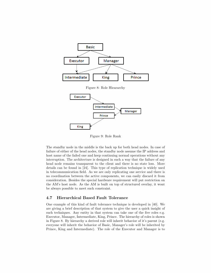
Figure 8: Role Hieararchy
Figure 9: Role Rank
The standby node in the middle is the back up for both head nodes. In case offailure of either of the head nodes, the standby node assume the IP address andhost name of the failed one and keep continuing normal operations without anyinterruption. The architecture is designed in such a way that the failure of anyhead node remains transparent to the client and there is no state loss. Moredetails can be found in [24]. This type of replication technique is widely usedin telecommunication field. As we are only replicating one service and there isno coordination between the active components, we can easily discard it fromconsideration. Besides the special hardware requirement will put restriction onthe AM’s host node. As the AM is built on top of structured overlay, it wontbe always possible to meet such constraint.
4.7 Hierarchical Based Fault Tolerance
One example of this kind of fault tolerance technique is developed in [40]. Weare giving a brief description of that system to give the user a quick insight ofsuch techniques. Any entity in that system can take one of the five roles e.g.Executor, Manager, Intermediate, King, Prince. The hierarchy of roles is shownin Figure 8. By hierarchy a derived role will inherit behavior of it’s parent (e.g.everyone will inherit the behavior of Basic, Manager’s role will be inherited byPrince, King and Intermediate). The role of the Executor and Manager is to
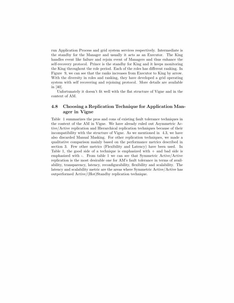
run Application Process and grid system services respectively. Intermediate isthe standby for the Manager and usually it acts as an Executor. The Kinghandles event like failure and rejoin event of Managers and thus enhance theself-recovery protocol. Prince is the standby for King and it keeps monitoringthe King throughout the role period. Each of the roles has different ranking. InFigure 9, we can see that the ranks increases from Executor to King by arrow.With the diversity in roles and ranking, they have developed a grid operatingsystem with self recovering and rejoining protocol. More details are availablein [40].
Unfortunately it doesn’t fit well with the flat structure of Vigne and in thecontext of AM.
4.8 Choosing a Replication Technique for Application Man-ager in Vigne
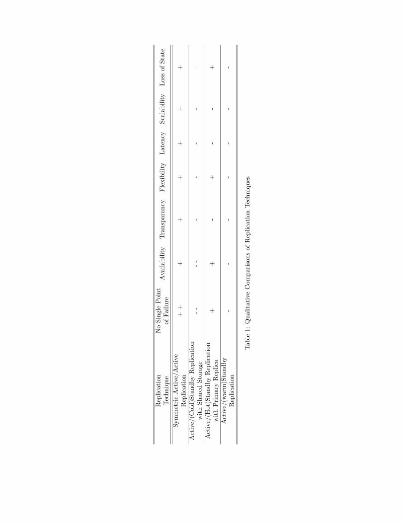
Table 1 summarizes the pros and cons of existing fault tolerance techniques inthe context of the AM in Vigne. We have already ruled out Asymmetric Ac-tive/Active replication and Hierarchical replication techniques because of theirincompatibility with the structure of Vigne. As we mentioned in 4.3, we havealso discarded Manual Masking. For other replication techniques, we made aqualitative comparison mainly based on the performance metrics described insection 3. Few other metrics (Flexibility and Latency) have been used. InTable 1, the good side of a technique is emphasized with + and bad side isemphasized with -. From table 1 we can see that Symmetric Active/Activereplication is the most desirable one for AM’s fault tolerance in terms of avail-ability, transparency, latency, reconfigurability, flexibility and scalability. Thelatency and scalability metric are the areas where Symmetric Active/Active hasoutperformed Active/(Hot)Standby replication technique.
Rep
licat
ion
Tec
hniq
ueN
oSi
ngle
Poi
ntof
Failu
reA
vaila
bilit
yT
rans
para
ncy
Fle
xibi
lity
Lat
ency
Scal
abili
tyL
oss
ofSt
ate
Sym
met
ric
Act
ive/
Act
ive
Rep
licat
ion
++
++
++
++
Act
ive/
(Col
d)St
andb
yR
eplic
atio
nw
ith
Shar
edSt
orag
e-
--
--
--
-–
Act
ive/
(Hot
)Sta
ndby
Rep
licat
ion
wit
hP
rim
ary
Rep
lica
++
-+
--
+
Act
ive/
(war
m)S
tand
byR
eplic
atio
n-
--
--
--
Tab
le1:
Qua
litat
ive
Com
pari
sons
ofR
eplic
atio
nT
echn
ique
s

5 Symmetric Active/Active Replication in Vi-gne
In this section, we describe Symmetric Active/Active replication formally andanalyze the feasibility of its implementation on top of a peer to peer framework.Then we address the kind of group communication infrastructure we need forreplicating AM in Vigne.
5.1 Basic Principle
A standard definition of Symmetric Active/Active replication can be found inEngelmann et al [12]. As we have described before, Symmetric Active/Activereplication ensures the availability by maintaining more than one analogousactive service components throughout the life time of the service. Like mostof the standby solutions, it doesn’t waste resource while keeping them idle.All the replicas are capable of serving client requests while running in virtualsynchrony without any need of failover. So there is no state loss or any serviceinterruption. The correctness of symmetric active/active replication lies in thefollowing properties.
1. Each replica runs in a non faulty node.
2. All replicas start from an identical initial state.
3. All replica process same sequence of commands deterministically.
With these three properties, they produce the same sequence of output bymaintaining same sequence of states. Replication is performed by total order-ing [20] all state change messages and reliably delivering them to the replica set.A process group communication is used to ensure total message order and reli-able delivery. The group communication also manages the replica set in case offailure. Furthermore, consistent output produced by all active replicas, may berouted through the group communication layer if the receiver of the output (e.g.client, Application Process, Resource Allocator, Application Monitor in case ofVigne) doesn’t have the ability to recognize duplicate message. As mentionedabove in Section4.5.1, it has the flexibility to enhance degree of replication bymodifying the replica set dynamically in case of high failure rate.
5.2 Active/Active Replication on top of DHT
In this sebsection we describe the underlying peer to peer network of Vigne. Wealso present our choice about physical nodes where all the replicas of AM willreside. Then we describe inherent problem of reconfiguration in cotext of thedynamic environment of Vigne.

Figure 10: Structured Peer to Peer Overlay Ring formed by Leafset
5.2.1 Pastry
Pastry is a self-organizing overlay network of nodes where each node is assigneda 128-bit unique node identifier (nodeid). The nodeid of a new joining node isassigned such a way that the set of all existing nodeid are uniformly distributed.When a message inserted with a destination key in the overlay, the message isrouted to the node whose nodeid is numerically closest to the destination key,among all existing nodes in the overlay on that particular moment. If thereare N existing nodes in the current overlay, Pastry can route a message to anydestination in less than log 2bN steps on average(b is a configuration parameterwith typical value 4). For efficient routing, each Pastry node maintains a routingtable and a leaf set. Leaf set contains IP addresses of the set of nodes withl/2 numerically closest larger nodeid and l/2 nodes with numerically closestsmaller nodeid relative to the host node’s nodeid (l is the maximum size of theleaf set with typical value 16). Pastry guarantees eventual delivery of a messageunless l/2 or more nodes with adjacent nodeid fail simultaneously. Pastry alsouses locality to minimize the distance traveled by a message. Its decentralized,scalable, self-organizing and efficient. For these four properties, Vigne has beenbuilt on top of Pastry. For reconfiguration of the leaf set and routing in case offailure or node arrivals, Vigne uses BAMBOO algorithm.
In Pastry peer to peer structured overlay, the leaf set forms a ring as shownin Figure 10. Application manager key (AM-Key) is randomly created after thejob is submitted by the client. The AM is created in a node whose nodeid isnumerically closest to the AM-Key among all the existing nodes in the overlay onthat moment and the AM-Key is sent back to the waiting client. Any messagesassociated with that application is routed through the structured peer to peeroverlay of Pasty using this AM-Key.

Figure 11: Natural Choice for Replica Set in Structured Peer to Peer Overlay
5.2.2 Location of the Replicas
In case of replicating AM, we need to choose a set of 2n+1 nodes ‡ where replicaswill reside. Here n is the degree of fault tolerance. There are two choices: (a)2n+1 nodes that are physically closest, (b) nodes that are numerically closestto the AM-key in the logical ring (Figure 10). The choice (a) is good in termsof performance as all the replicas will reside closely in geographical point ofview and the underlying group communication will be considerably fast. Butthen we will run the risk of putting all the replicas in the same cluster andthus losing all the AM’s in case of failure in the whole cluster. With choice (b),the probability of putting all the replicas in the same cluster will be reducedbecause of the uniform distribution of keys in DHT namespace. So the naturalchoice of replica set will be 2n+1 numerically closest nodes in the current overlayrelative to AM-Key. We are going to choose 2n+1 replicas from the leaf set inPastry layer. As the replica set will always be a subset of leaf set, any failureinformation in the leaf set can used to detect the failure in the replica set.
Another way of selecting replica set is as follows. The replica set of a AMwill contain the node whose nodeid is the closest to the AM-Key. Immediaten left neighbors and n right neighbors of the previously selected node will bein the replica set as shown in Figure11. We are going to follow this selectionmechanism†.
5.2.3 Study of Reconfiguration Cases
Throughout this subsection, the degree of fault tolerance is taken as one. So weneed three replicas to tolerate one failure. The set of replica is named as replicachain and the set is marked by a shaded region in the corresponding figures.
‡Later in Section 6, we will see that we have selected a consensus based protocol forimplementing Symmetric Active/Active replication in Vigne. In asynchronous distributedsystem with failure, consensus requires minimum 2n+1 nodes to tolerate n failures.
†We could have taken 2n+1 closest nodes as replica set. There isn’t any relative advantageor drawback between this two ways

The replica whose key is the closest to the AM-Key is called the central replica.All other replicas will be referred as wing replica.
We have already mentioned that a process group communication amongthe replica set is used to ensure total message order and reliable delivery. Wewill give the necessary specification of it in section 5.3. For the time beinglet’s assume that the regarded group communication is performed using VirtualReplica set †.
Lets assume that there are two basic types of application related messagesin the system with Virtual Replica set: Application Message and Shadow Ap-plication Message. An Application Message is delivered to the central replicausing the routing algorithm of Pastry structured overlay. Upon receiving a Ap-plication message, the central replica creates a analogous Shadow ApplicationMessage and sends the message to its closest left and right neighbors in theleaf set using IPaddress. ‡ The central replica also consumes the ApplicationMessage itself. The receiving of a Shadow Application Message doesn’t createanymore message §. Upon receiving a Shadow Application Message, a replicahandles it as an Application Message and doesn’t forward it to any other nodesanymore.
It may happen that there is one failure or one node arrival inside the replicaset DHT namespace. In Figure12, four distinguished cases are presented: (a)a new node arrival whose nodeid is closer to the AM-Key than former centralreplicas nodeid, (b) a new node arrival whose nodeid is no more closer to theAM-Key than nodeid of the former central replica,(c) failure of the centralreplica, (d) failure of a wing replica. In all the four cases some replica receivesthe application messages given that there is no failure during the forwardingperiod.
There may be two failures¶ or two node arrivals inside the replica set names-pace in DHT. In Figure13, four distinguished cases are presented: (a) two newnodes arrival; one of which id is numerically closer to the AM-Key than formercentral replica’s nodeid, (b) two new nodes arrival where no one’s id is closerto the AM-Key than nodeid of former central replica,(c) failure of the centralreplica and a wing replica, (d) failure of two wing replicas. In all the four casessome replica receives the application messages given that there is no failureduring the forwarding period.
Three new nodes may arrive at the same time inside the replica set names-pace in DHT. In Figure 14, four distinguished cases are presented: (a) threenew nodes should be the new Virtual Replica set, (b) the former central replicaand two new nodes should be the new Virtual Replica set, (c) a former wing
†A few researcher has addressed Virtual Replica set in literature. It simply means thatno information about the replica set corresponding to a AM is maintained in anywhere. Ata given moment, k nodes closest to the AM-Key forms the Virtual Replica set. Here k is thecardinality of the replica set.
‡As no physical replica set is maintained, the wing replicas should be the immediate rightand left neighbor of the central replica in it’s leafset.
§Note that this may lead to message duplication in the overlay.¶A set of three replicas can’t tolerate two failures in active/active replication. We addressed
the case of two failures to represent the problem clearly

Figure 12: Single Failure or Single Node arraival in the Replica Set namespace
Figure 13: Two Failures or Two Node arraivals in the Replica Set namespace
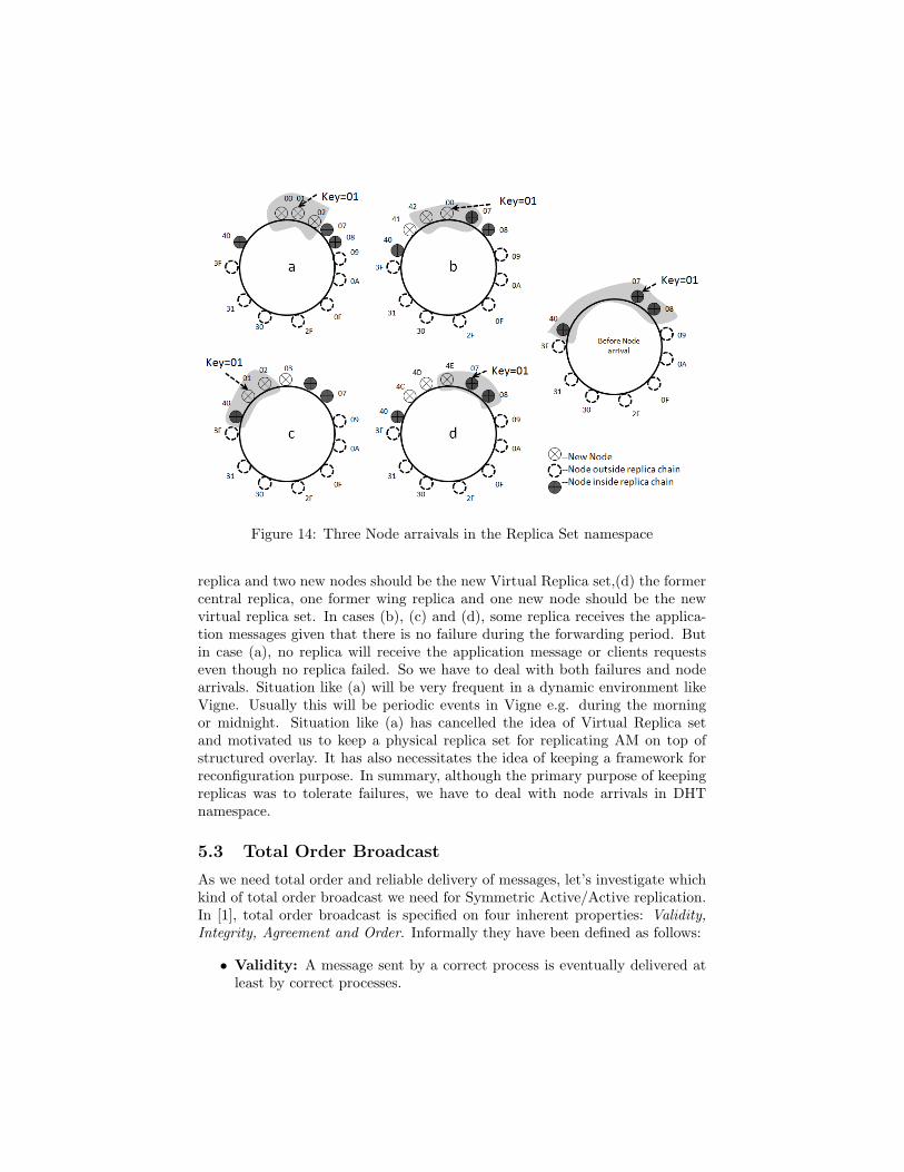
Figure 14: Three Node arraivals in the Replica Set namespace
replica and two new nodes should be the new Virtual Replica set,(d) the formercentral replica, one former wing replica and one new node should be the newvirtual replica set. In cases (b), (c) and (d), some replica receives the applica-tion messages given that there is no failure during the forwarding period. Butin case (a), no replica will receive the application message or clients requestseven though no replica failed. So we have to deal with both failures and nodearrivals. Situation like (a) will be very frequent in a dynamic environment likeVigne. Usually this will be periodic events in Vigne e.g. during the morningor midnight. Situation like (a) has cancelled the idea of Virtual Replica setand motivated us to keep a physical replica set for replicating AM on top ofstructured overlay. It has also necessitates the idea of keeping a framework forreconfiguration purpose. In summary, although the primary purpose of keepingreplicas was to tolerate failures, we have to deal with node arrivals in DHTnamespace.
5.3 Total Order Broadcast
As we need total order and reliable delivery of messages, let’s investigate whichkind of total order broadcast we need for Symmetric Active/Active replication.In [1], total order broadcast is specified on four inherent properties: Validity,Integrity, Agreement and Order. Informally they have been defined as follows:
• Validity: A message sent by a correct process is eventually delivered atleast by correct processes.

• Integrity: For any message m, it will be delivered only once by a processif it was previously sent by some process.
• Agreement: At least non-faulty processes deliver same set of messages.
• Order: At least all non-faulty processes delivers the same set of messagesit receives in same order.
Moreover the dimension of uniformity has given total order specification anew flavor. As we find in [1]:
• Uniformity: A uniform property imposes some restriction on the histo-ries of (at least)correct processes on the basis of some events occurred inthe histories of some processes.
• Non-uniformity: A non-uniform property imposes some restriction onthe histories of correct processes on the basis of some events in the historiesof some correct processes.
As it is not possible to compel a failed process eventually delivering a messagethat he has sent, we can ignore Uniform Validity. And if we are in a crash-failure environment, the uniform version of Integrity can be enforced withoutany additional overhead. So the other versions of Integrity is discarded.
On the other hand depending on the message delivered by a faulty processand strength of delivered message order, there can be four different kind oforders:Strong Uniform Total Order, Weak Uniform Total Order, Strong Non-uniform Total Order and Weak Non-uniform Total Order. So with two choicesfor Agreement and four choices for order, there can be eight different kind of totalorder broadcast algorithm. For our active/active replication purpose we havechosen: Uniform Agreement and Strong Uniform Total Order. Because withthis specification, all correct processes deliver same sequence of message and allfaulty processes deliver a prefix of the sequence of message already delivered bysome correct process. So the replicas will maintain same sequence of state anda wrong message from a faulty replica will not compromise the consistency ofthe system. In literature this kind of algorithm is known as Atomic Broadcast.The selected total order specification is described below as given in [1]:
• Non-uniform Validity(NUV): If a correct process total order broad-casts a message m, then it eventually total order delivers m.
• Uniform Integrity(UI): For any message m, every process p total orderdelivers m at most once and only if m was previously total order broad-casted by some process.
• Uniform Agreement(UA): If a process total order delivers a messagem, then all correct processes eventually total order delivers m.
• Strong Uniform Total Order(SUTO): If some process total orderdelivers some message m1 before m2, then a process total order deliversm2 only after it has total order delivered m1.
6 Specifications of the Symmetric Active/ActiveReplication Architecture
In the previous section, we explained why we have chosed Atomic Broadcastfor Symmetric Active/Active replication of AM in Vigne. The purpose of thissection is to make the necessary specification to implement Atomic Broadcastin our context. Side by side, we will describe the complete architecture stackneeded for Symmetric Active/Active replication and make the correspondingdesign choice to achieve high performance.
6.1 Atomic Broadcast
There are many different kinds of Atomic Broadcast algorithms in literature thatprovide the total order property mentioned in section 5.3. We are intending tochoose the best available one. From the optimization point of view, there arethree classes of atomic broadcast algorithms:
• Algorithm that preserves the states consistent among all the replicas. Herethe clients are provided consistent service [30]
• Algorithm that let internal inconsistency arises in server side and keepsthe client ignorant about the inconsistency. So there will be no externalconsistency [19].
• Algorithms that allows both types of inconsistency: internal and exter-nal [3, 13]. But later recover the consistency by undoing some messagedelivery.
We are not allowing any kind of inconsistency in AM replica set or in clientside. Because some actions will be hard (probably impossible) to undo. Ifwe allow inconsistency in AM side, to undo it we might have to make lotsof modification in AM as well as in other parts of the system (e.g. ResourceAllocator, Application Monitor). Besides as the client will be acting as one shot,it will not be possible to undo some actions in client side. The client might havequitted by this time after receiving his result.
There are also different flavors of Atomic Broadcast algorithm from otherdimensions. A complete survey of Atomic Broadcast algorithm can be found in[8]. They have made a classification depending upon the mechanism used forordering messages. We investigated three types of algorithms: Fixed SequencerBased, Token Based and Destination Agreement on message set.
• Fixed Sequencer: A process is elected as sequencer and is responsiblefor ordering messages. As long as there is no failure, there is only a sin-gle sequencer in the system and no other process tries to order messages.In case of the failure of the sequencer, the algorithm is moved to a fail-ure mode where a new sequencer is elected and some messages might beundone depending upon the algorithm. The failure is handled throughcertain group communication mechanisms [3].

• Token Based: This is pretty much similar to fixed sequencer based algo-rithm except the role of the sequencer isn’t dedicated to a single process.Rather it rotates between processes even if there isn’t any failure. Theprivilege to order a set of message is represented by a token. A processcan order the broadcasted messages if he is the current token holder. Thefailure of the token holder is handled through certain group communi-cation primitives. The reason behind development such algorithm is todistribute the load among processes [9].
• Destination Agreement on Message set: The delivery order is formedby an agreement between destination of the messages. It transforms totalorder broadcast problem into a sequence of consensus problem. Each in-stance of consensus decides on the sequence of messages to be delivered [7].
From another dimension, the necessity of physical clock puts all AtomicBroadcast algorithms into two categories: Time Free and Time Based. Most ofthe atomic broadcast algorithms fall into the category of time free algorithm.
Among all available options for Atomic Broadcast algorithm, we have de-cided to go with Destination Agreement class (Agreement on message set)mainly because it provides the total order that is identical to our choice (NUV,UI, UA and SUTO). It has sufficient modularity and provides substantial flexi-bility to replicate an existing system. Here a suspicion of a process in the failuredetector layer doesn’t necessarily compel process exclusion. Rather suspicion ofprocesses is used to keep the consensus layer live. It is time free and doesn’tallow any inconsistency in client side or replica side.
The fixed sequencer algorithms have promising performance in the absenceof failure e.g. Optimistic Atomic Broadcast [19]. But in case of failure, theyperform worse. So we discarded Fixed Sequencer Based Algorithms.
According to many authors, token based algorithms are considered good interms of throughput. Unfortunately most of the token based algorithms exceptEkwall et al [9] are on top of group membership layer. The reason behindavoiding such algorithm is explained in Sections 6.6 and 6.7. Ekwall et al [9]has analogous performance with agreement based Mostefaoui-Raynal [27] andChandra-Toueg [7] in terms of Latency and Throughput. In [11], it is confirmedthat the performance ranking of Ekwall et al, Mostefaoui-Raynal and Chandra-Toueg remains same in wide area network. As Vigne is a large grid, the choicebetween these three doesn’t matter anymore.
In Summary, we have decided to choose an Atomic Broadcast algorithm thatwill not allow any kind of inconsistency in AM or in Client or in other part of thesystem (e.g. Resource Allocator, Application Monitor). Meanwhile the messageorder of the algorithm should be based on destination agreement on message setto be delivered. Such algorithms are available in [37, 36]. To implement thiskind of Atomic Broadcast algorithm we will need a Consensus layer which raisesthe need of a Failure Detector of its own kind. Hence we need three layers sofar: Atomic Broadcast, Consensus and Failure Detector. The inherent propertyof Atomic Broadcast necessitates the need for a reliable channel.
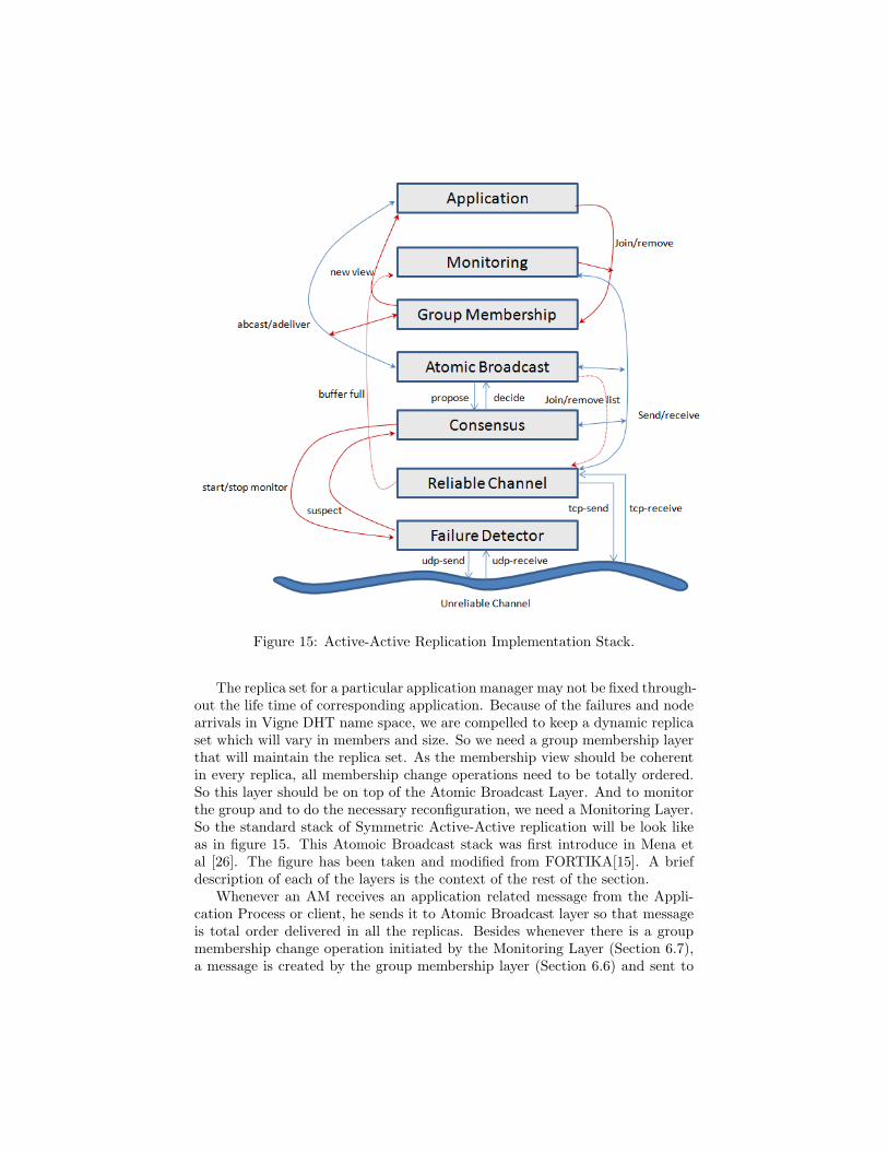
Figure 15: Active-Active Replication Implementation Stack.
The replica set for a particular application manager may not be fixed through-out the life time of corresponding application. Because of the failures and nodearrivals in Vigne DHT name space, we are compelled to keep a dynamic replicaset which will vary in members and size. So we need a group membership layerthat will maintain the replica set. As the membership view should be coherentin every replica, all membership change operations need to be totally ordered.So this layer should be on top of the Atomic Broadcast Layer. And to monitorthe group and to do the necessary reconfiguration, we need a Monitoring Layer.So the standard stack of Symmetric Active-Active replication will be look likeas in figure 15. This Atomoic Broadcast stack was first introduce in Mena etal [26]. The figure has been taken and modified from FORTIKA[15]. A briefdescription of each of the layers is the context of the rest of the section.
Whenever an AM receives an application related message from the Appli-cation Process or client, he sends it to Atomic Broadcast layer so that messageis total order delivered in all the replicas. Besides whenever there is a groupmembership change operation initiated by the Monitoring Layer (Section 6.7),a message is created by the group membership layer (Section 6.6) and sent to

atomic broadcast layer. The Atomic Broadcast layer provides necessary inter-faces for these two tasks. When the underlying consensus layer decides a set ofmessage to be atomically delivered, he sends membership change message andapplication related message to the Group Membership layer and ApplicationManager respectively. In case of the presence of a replica remove operation inthe decision message set of the consensus, he updates the reliable channel aboutthe event so that the sending queue related to that failed peer is cleared.
6.2 Unreliable Channel
The unreliable channel is any physical communication channel where the mes-sage transmission isn’t guaranteed or ordered. All messages will be sent throughunreliable channel whether it needs a reliable delivery or not.
The underlying Pastry communication framework will be used as unreliablechannel.
6.3 Reliable Channel
A channel between P and Q is reliable if it doesn’t create or duplicate messagesand every messages sent by P to Q is eventually received by Q given that Q isa correct process.
In real system we can have a fair lossy channel between P and Q where nomessage is duplicated or created, message can be lost but, if P sends an infinitenumber of messages to Q and Q executes receive actions infinitely often, thenit receives an infinite number of messages from P. Usually the reliable channelis built upon a fairy lossy link through retransmission and acknowledgementmechanisms. A detail description of solving this quiescence problem can befound in [31].
Usually the reliable channel is implemented with TCP [10] send, receive andtimeouts. All the upper layers in the stack uses reliable channel to exchangemessages with corresponding peers in other replicas. Besides buffer overflow orempty buffer in sending or receiving queue can be used to inform the upperlayers (e.g. Monitoring Layer) about potential suspected replicas. This infor-mation will be helpful for the Monitoring Layer to issue or refine reconfigurationcommands.
6.4 Consensus
The consensus problem is the most basic building block of many agreementproblems in distributed fault tolerant application such as atomic broadcast,group membership, atomic commit etc. It is defined by the following threeproperties:
1. Termination: Eventually every correct process decides on some value.
2. Validity: If a process decides a value v, then v was proposed by someprocess.

3. Agreement: No two correct process decide differently.
The FLP result showed the impossibility of Consensus in asynchronous dis-tributed system in presence of a single system failure [14] . Later Chandra andToueg introduced the idea of unreliable failure detector to solve consensus in asystem in presence of failure [7]. Hence we need a failure detector to solve theconsensus problem in Vigne.
Different Consensus algorithm has been proposed in literature. To mentiona few: Chandra-Toueg S [7], Mostefaoui-Raynal S [27] and Lamport’s Paxosalgorithm [22, 21]. Paxos requires an Ω failure detector. The description ofdifferent kind of failure detectors are available in next subsection.
We have decided to use Paxos because it is safe even if there is failure.The liveness of Paxos can be enhanced through randomization. It can also beimplemented without stable storage and performs well in dynamic environment.It can work both with dynamic or static group. It provides concurrency i.e.separate instance of consensus can run independently at the same time. Finallyimplementing consensus in asynchronous system is a cumbersome job and Paxosis well documented.
Whenever the Atomic Broadcast layer receives some message to atomicallydeliver to all the replicas in current view, he invokes propose method of Con-sensus layer. The Consensus layer starts a new instance of consensus if he isthe current leader of the replica set and decides the set of messages to deliverin current round and informs all the replicas (including himself) in current viewabout the decision. Upon receiving the decision set of messages, the Consensuslayer delegates the responsibility of handling the messages to Atomic Broadcastlayer. Besides the Consensus layer tells the failure detector layer to periodi-cally monitor the leader so that in case of failure of the leader the consensusdoesn’t stall forever. All the messages related to the consensus algorithm aretransmitted through reliable channel.
6.5 Failure Detector
Informally the failure detector is a component in the system that informs theupper layer about the faulty nodes in the underlying network. Depending uponthe service it provides (quality of information), there are several types of failuredetectors [35]:
1. S: It is defined by two properties: eventually every process that crashesis permanently suspected by every correct process (strong completeness)and there is a time after which some correct process is never suspected byany correct process (eventual weak accuracy).
2. P: It is defined by two properties: eventually every process that crashesis permanently suspected by every correct process (strong completeness)and there is a time after which correct processes are not suspected by anycorrect process (eventual strong accuracy).
3. Ω: It outputs a single correct process and there is a timer after which allthe correct process always trusts the same correct process (eventual leaderproperty).
A good description of failure detectors for asynchronous system is availablein [31].
The Failure Detector in Figure 15 is Consensus layer specific. Dependingupon the selected consensus algorithm, the choice of failure detector will change.All three types of failure detectors described in 6.5 provides enough synchronyto solve consensus. However it has been proved that S and Ω are the weakestfailure detector to solve consensus in distributed system in presence of failure [6].
As we have already chosen Paxos in consensus layer, the failure detector weneed is Ω. The failure detector in the stack is built upon unreliable channel andits purpose is to monitor the leader of the current replica set. In case of a failureof the leader, it will inform the consensus layer about the failure so that thehost node can start the current (unfinished) instance of consensus immediately.
6.6 Group Membership
The implementation of AM on top of structured peer to peer overlay and thedynamic environment of Vigne have leaded us to a dynamic group management.Regarding group communication, we need to maintain a view of the groups andprovide necessary interface to other layers of the stack (e.g. Monitoring Layer,Consensus Layer, and Atomic Broadcast Layer) so that they can learn aboutcurrent members of the group. Group Membership layer also provides interfacefor member addition and removal.
In many implementation of active replication, group membership layer isused for fault detection. But in our case group management and fault detectionare completely decoupled. This will add additional flexibility to the imple-mentation and enhance the performance of the system. Because suspicion of amember in the failure detector will not necessarily lead to a membership changeand costly state transfer. Thanks to Mena-Schiper for coming up with thisvaluable idea [26].
Group Membership is located on top of Atomic Broadcast layer to maintainconsistent view among all the replicas in case of failure or reconfiguration. Anymembership change is atomically broadcasted like application messages in thecurrent replica set. The member addition and removal operations are not ini-tiated by the group membership layer itself. Another layer called Monitoringlayer initiates a membership change through the interface provided by the groupmembership layer. We will see later that Monitoring Layer performs all the jobsrelated to reconfiguration. Whenever a membership change is initiated by theMonitoring Layer, the Group Membership layer sends the membership changemessage to the Atomic Broadcast layer. If a membership change message isatomically delivered by the Atomic Broadcast layer, it takes action and informsthe application layer about the new view.

6.7 Monitoring
In our design choice, replica suspicion and exclusion is decoupled. Replica ex-clusion will not be initiated whenever there is a suspicion in the Failure Detectorlayer. The Failure Detector and Group Membership component don’t have theauthority to make this decision. Rather a new component above the group mem-bership layer, specifically Monitoring Layer takes such decision. This separationof responsibility provides greater flexibility [26] and high performance.
As we are using Paxos in consensus layer, the necessary failure detector Ωshould elect a leader in the current view. Meanwhile the suspicion of the leadershould be informed back to the Consensus layer so that the consensus doesn’tstall indefinitely in case of true failure of the leader. But a false suspicion shouldnot lead to the exclusion of the suspected node from the replica set. So in caseof a suspicion provided by the Failure Detector layer, the Monitoring layer mon-itors the suspected node (probably with the interface provided by the FailureDetector Layer with a large timeout value e.g. in the order of minutes) [26].Here a suspicion will compel the monitoring layer to initiate a replica removaloperation in the group membership layer. To avoid unnecessary replica removaland improve performance, the monitoring layer might consult the situation withhis peer in other replicas and decide only to remove a particular replica when itlearns that a threshold number of peers have suspected the same replica. Otherthan removing a failed replica from the replica set, Monitoring layer will also dothe job of reconfiguration by handling any leaf set change events e.g. (a) NodeFailure Event, (b) Node Arrival Event, (c) Leaf Set Recovered from RoutingTable, (d) Leaf Set Merge, (e) Node Join Event. To make good reconfigurationit also gets information from the reliable channel layer about overflow of sendingqueue of a node [26, 4]. The task of reconfiguration is described in a separatesection later.
6.8 Application Manager
AM is the component that we want to replicate. We have already described AMin section 1. AM is implemented as a deterministic finite automata. Whenevera message arrives from an application process or some client, the AM send it tothe atomic broadcast layer. It also handles the message atomically delivered bythe Atomic Broadcast layer in a deterministic way. During the implementationphase we have to make sure that any change in the AM code doesn’t compromisethis property. After replication AM in vigne will look like as in Figure16.
7 Reconfiguration and Monitoring Layer
As described in section 6.7, Monitoring layer is responsible for the reconfigu-ration of the replica set by handling failures and new node arrivals in DHTnamespace. It will issue any kind of member addition or removal operationin the current replica set. While issuing such reconfiguration commands, themonitoring layer will maintain the following invariance: (a) In case of need for a

Figure 16: Client-Application Manager-Application Process Interaction in repli-cated model.
Figure 17: Three Replicas in a DHT name space
remove operation (may not be a failed node) in current view the node with themost distant nodeid relative to AM-Key will be removed by keeping the bestpossible symmetry, (b) any new view should have majority of members fromthe old view to deal with unsuccessful state transfer. Because of the dynamicenvironment of Vigne, the reconfiguration has to deal with two major problems:(a) high churn rate, (b) routed message during reconfiguration. The purposeof this section is to introduce these problems informally and propose possiblesolution.
7.1 Problem with High Churn Rate
In this section, we will focus on the problem of high node arrival rate. Asthe case of failure has been described previously in context of failure detector,consensus and monitoring layer, we are skipping it. If there wasn’t any failureor node arrival after the job submission, three † AM replicas should be runningas in Figure 17. When a new node will arrive inside the replica set namespace(Figure 18), the monitoring layer might issue a membership change through thegroup communication layer. After the state transfer is complete, there mightbe four consistent replica at an instance (Figure 19). As increased number ofreplicas will increase the overhead of Paxos, monitoring layer will remove one
†Here the size of replica set is three as the degree of fault tolerance is taken as one
Figure 18: New Node Arrived in the DHT namespace
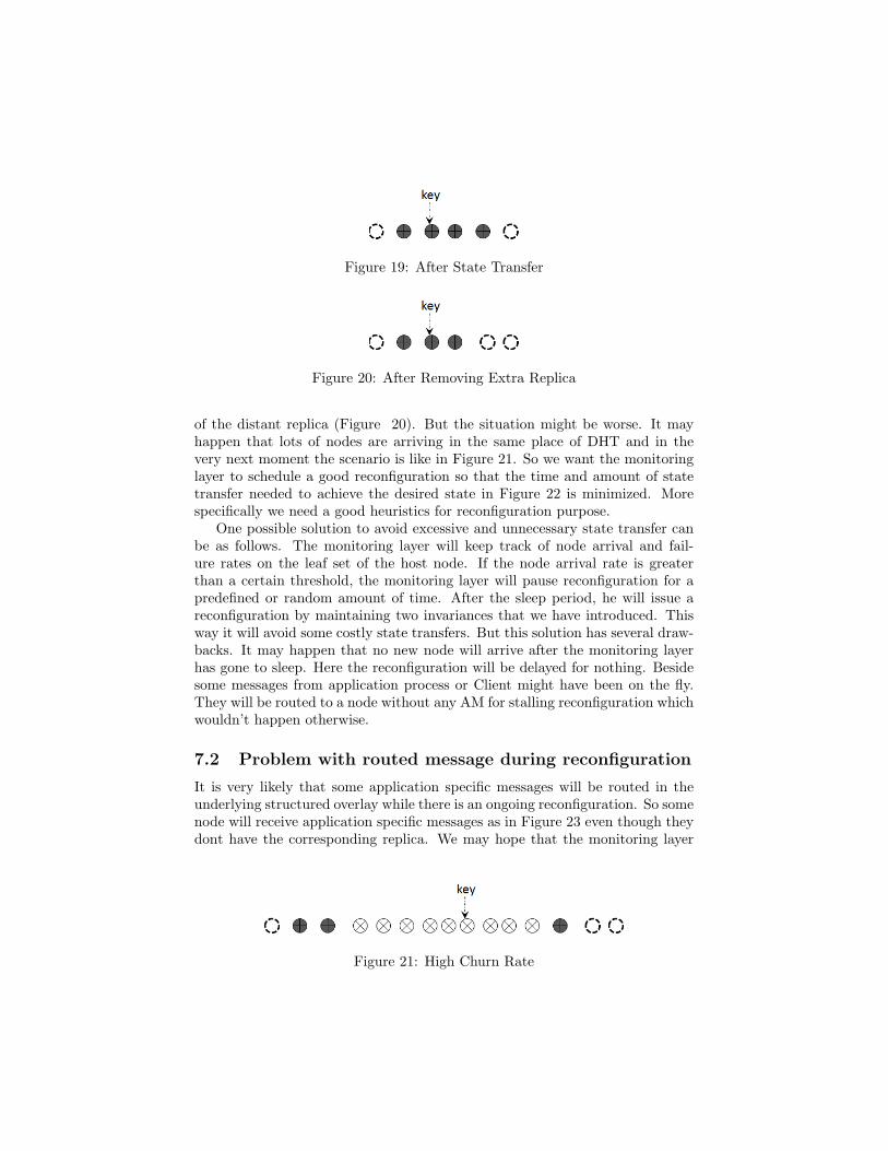
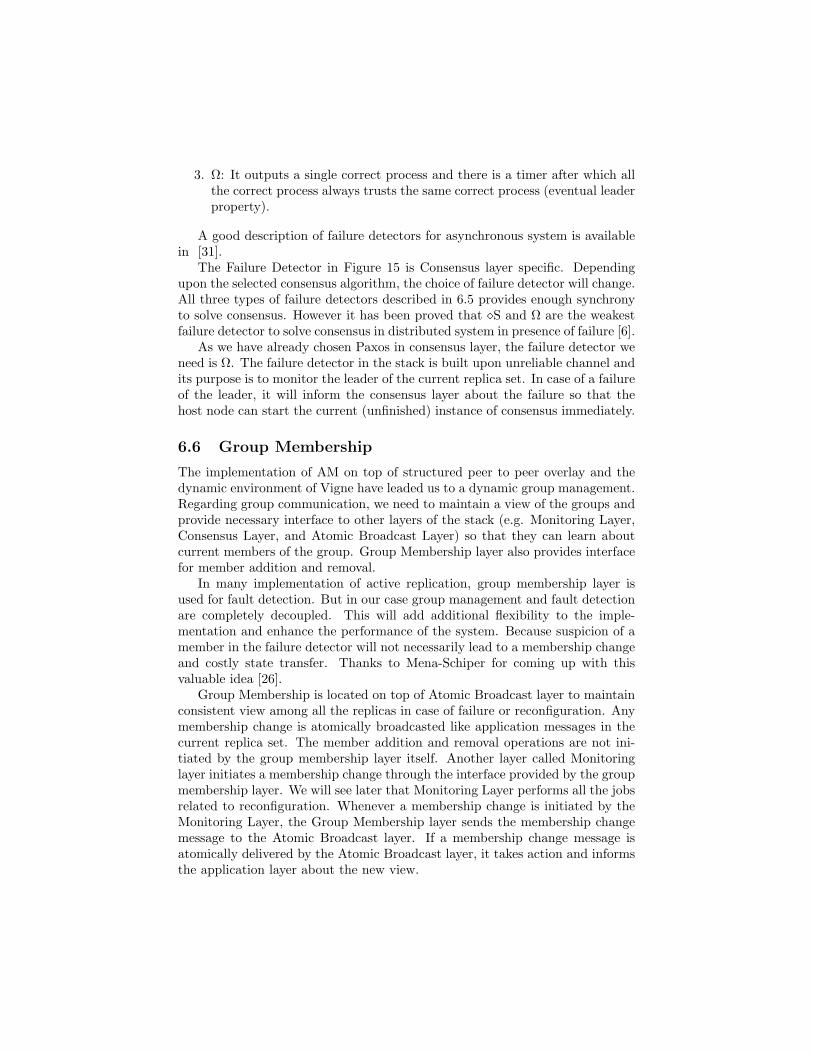
Figure 19: After State Transfer
Figure 20: After Removing Extra Replica
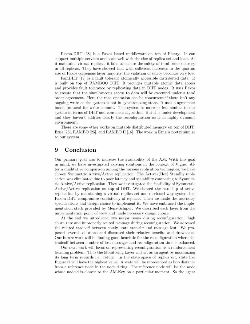
of the distant replica (Figure 20). But the situation might be worse. It mayhappen that lots of nodes are arriving in the same place of DHT and in thevery next moment the scenario is like in Figure 21. So we want the monitoringlayer to schedule a good reconfiguration so that the time and amount of statetransfer needed to achieve the desired state in Figure 22 is minimized. Morespecifically we need a good heuristics for reconfiguration purpose.
One possible solution to avoid excessive and unnecessary state transfer canbe as follows. The monitoring layer will keep track of node arrival and fail-ure rates on the leaf set of the host node. If the node arrival rate is greaterthan a certain threshold, the monitoring layer will pause reconfiguration for apredefined or random amount of time. After the sleep period, he will issue areconfiguration by maintaining two invariances that we have introduced. Thisway it will avoid some costly state transfers. But this solution has several draw-backs. It may happen that no new node will arrive after the monitoring layerhas gone to sleep. Here the reconfiguration will be delayed for nothing. Besidesome messages from application process or Client might have been on the fly.They will be routed to a node without any AM for stalling reconfiguration whichwouldn’t happen otherwise.
7.2 Problem with routed message during reconfiguration
It is very likely that some application specific messages will be routed in theunderlying structured overlay while there is an ongoing reconfiguration. So somenode will receive application specific messages as in Figure 23 even though theydont have the corresponding replica. We may hope that the monitoring layer
Figure 21: High Churn Rate

Figure 22: Desired Good Configuration
Figure 23: Message During Reconfiguration
will make a favorable reconfiguration such that these receiver nodes will beincluded inside the replica set and the queued messages will be handled. Butthe situation might be worse. Before the Monitoring layer has instantiated thementioned reconfiguration, some more nodes may arrive and the current DHTnamespace may look like as in Figure 24. And it may go on for couple of rounds.So the application specific messages might be scattered throughout the DHTnamespace.
There are several choices to deal with this situation. We can simply discardthe message by forcing application process or client to resend the message ifthe host node doesn’t contain the corresponding AM. This will compromise thetransparency of the system and reduce the performance as well as the availabilityof the AM even though there isn’t any failure. Another choice is to keep themessages in a queue and send a search message to some selected node in leafset with the AM-Key (Figure 25). If a good replica receives such message,he will send back a reply and initiate a membership change to include thatnode into the replica set. So the underlying reconfiguration heuristic can be ”Anode receiving a application specific message will be eventually included intocorresponding applications AM replica set”. But it has several drawbacks. Thismight lead to lots of state transfer and will reduce the performance. From thispoint of view we also need a good heuristic for the reconfiguration to balance
Figure 24: Message During Reconfiguration (Snapshot 2)

Figure 25: Reconfiguration Using Search Message
the tradeoff between reconfiguration time and message lost in highly dynamicenvironment.
A possible solution is depicted in Figure 25. When a node receives an ap-plication specific message, it will check whether its host node contains suchreplica. If the answer is yes then the processing is straightforward. If the an-swer is no, then he will send a search message to several neighbors in his leaf setring with the AM-Key and IP-Address piggybacked inside the message. If somegood replica receives this search message, good replica will send a reply backto the sender of search message using the IP-Address. This reply will containthe IPaddress of the current replica set. After receiving this reply, the nodewill re-compute its eligibility of being in the replica set. If he isnt eligible forthe replica set of the corresponding AM-Key he will forward the queued mes-sages to good replicas using IP-Addresses. If he is still eligible he will send ajoin message with the queued messages to the good replicas. After receiving ajoin message, monitoring layer of good replicas will run a consensus and decidewhether the node should be included inside the replica set or not. The resultwill be sent back to the node requesting join.
8 Related Work
In this section we give a short description of some projects that implementedAtomic Multicast on top of DHT.
Scribe [5] is a multicast framework developed on top of Pastry. It pro-vides efficient application level multicast and is scalable in terms of number ofgroups, group size and number of messages. It uses the underlying failure de-tection, locality and reliability property of Pastry for group management andreconfiguration. Unfortunately it doesn’t ensure reliable and ordered delivery.
Paxon-DHT [38] is a Paxos based middleware on top of Pastry. It cansupport multiple services and scale well with the size of replica set and load. Asit maintains virtual replicas, it fails to ensure the safety of total order deliveryin all replicas. They have showed that with sufficient increases in the quorumsize of Paxos consensus layer majority, the violation of safety becomes very low.
FamDHT [18] is a fault tolerant atomically accessible distributed data. Itis built on top of BAMBOO DHT. It provides mutable atomic data accessand provides fault tolerance by replicating data in DHT nodes. It uses Paxosto ensure that the simultaneous access to data will be executed under a totalorder agreement. Here the read operation can be concurrent if there isn’t anyongoing write or the system is not in synchronizing state. It uses a agreementbased protocol for write commit. The system is more or less similar to oursystem in terms of DHT and consensus algorithm. But it is under developmentand they haven’t address clearly the reconfiguration issue in highly dynamicenvironment.
There are some other works on mutable distributed memory on top of DHT:Etna [28], RAMBO [25], and RAMBO II [16]. The work in Etna is pretty similarto our system.
9 Conclusion
Our primary goal was to increase the availability of the AM. With this goalin mind, we have investigated existing solutions in the context of Vigne. Af-ter a qualitative comparison among the various replication techniques, we havechosen Symmetric Active/Active replication. The Active/(Hot) Standby repli-cation was eliminated due to poor latency and scalability comparing to Symmet-ric Active/Active replication. Then we investigated the feasibility of SymmetricActive/Active replication on top of DHT. We showed the hardship of activereplication by maintaining a virtual replica set and disclosed why system likePaxon-DHT compromise consistency of replicas. Then we made the necessaryspecifications and design choice to implement it. We have embraced the imple-mentation stack provided by Mena-Schiper. We described each layer from theimplementation point of view and made necessary design choice.
At the end we introduced two major issues during reconfiguration: highchurn rate and improperly routed message during reconfiguration. We adressedthe related tradeoff between costly state transfer and message lost. We pro-posed several sollutions and discussed their relative benefits and drawbacks.Our future work will be finding good heuristic for the reconfiguration where thetradeoff between number of lost messages and reconfiguration time is balanced.
Our next work will focus on representing reconfiguration as a reinforcementlearning problem. Thus the Monitoring Layer will act as an agent by maximizingits long term rewards i.e. return. In the state space of replica set, state likeFigure17 will have the highest value. A state will be represented as hop distancefrom a reference node in the nodeid ring. The reference node will be the nodewhose nodeid is closest to the AM-Key on a particular moment. So the agent
will be in state < 1, 0,−1 > when the replica sets are as in Figure17. Andthe agent will be in state < 1,−1,−2 > as in Figure18. The state of theagent will change with the dynamic environment even though the agent isn’ttaking any action. The possible action space for the agent in certain state s isA(s) = Replica−Removal(nodeid), State−Transfer(nodeid), Do−Nothing.As long as there isn’t any failure or node arrival the agent will keep receiving 0rewards in state < 1, 0,−1 >. Our next research will focuse on how to modelthe negative rewards in case of a failure or a node arrival or a state transfer andselect a suitable algorithm to solve this problem. We believe that the agent willalways come up with an optimal policy if we can model the reward accordingto the dynamism in DHT namespace.
In future we also want to replicate the Resource Allocator and ApplicationMonitor, using the same specification that we have made for AM.
Acknowledgements I acknowledge my supervisor Thomas Ropars for hisconstant and precious guidance during this work. I also acknowledge seniorresearcher Cristine Morin for her periodic and valuable feedback. I also wantto acknowledge Dr. Robert C. Ward and Dr. Arif Dowla whose recommenda-tions have helped me to get this great opportunity of working in such a niceenvironment.
References
[1] R. Baldoni, S. Cimmino, and C. Marchetti. Total Order CommunicationsOver Asynchronous Distributed Systems: Specifications and Implementa-tions. Technical report, Universit‘a di Roma ”La sapienza”, January 2004.
[2] BAMBOO. http://bamboo-dht.org/.
[3] K. Birman, A. Schiper, and P Stephenson. Lightweight Casual and AtomicMulticast. Transaction on Computer System, 9(3):272 – 314, August 1991.
[4] B. Charron Bost, X. Defago, and A. Schiper. Broadcasting Messagesin Fault-Tolerant Distributed Systems: The Benefit of Handling Input-Triggered and Output-Triggered Suspicions Differently. In Proceedings ofthe Symposium on Reliable Distributed Systems, pages 244–249, 2002.
[5] M. Castro, P. Druschel, A-M. Kermarrec, and A. Rowstron. Scribe: ALarge-Scale and Decentralized Application-Level Multicast Infrastructure.IEE Journal on Selected Area in Communications SAC, 20:1489–1499,2002.
[6] T. D. Chandra, V. Hadzilacos, and S. Toueg. The Weakest Failure Detectorfor Solving Consensus. Journal of ACM, 43(4):685 – 722, July 1996.
[7] T. D. Chandra and S. Toueg. Unreliable Failure Detectors for ReliableDistributed Systems. Journal of the ACM (JACM), 43:225 – 267, March1996.

[8] X. Dfago, A. Schiper, and P. Urbn. Total Order Broadcast and MulticastAlgorithms: Taxonomy and Survey. ACM Computing Surveys (CSUR),36(4):372 – 421, December 2004.
[9] R. Ekwall, A. Schiper, and P. Urban. Token Based Atomic Broadcastusing Unreliable Failure Detectors. In In Proceedings of 23nd IEEE In-ternational Symposium on Reliable Distributed Systems (SRDS’04) (Flo-rian’opolis, Brazil)., pages 52–65. IEEE Computer Society Press., 2004.
[10] R. Ekwall, P. Urban, and A. Schiper. Robust TCP Connections for FaultTolerant Computing. Journal of Information Science and Engineering,19(3):503 – 516, 2003.
[11] Richard Ekwall and Andr Schiper. Comparing Atomic Broadcast Algo-rithms in High Latency Networks. Technical report, Ecole PolytechniqueFederale de Lausanne (EPFL), 2006.
[12] C. Engelmann, S. L. Scott, C. Leangsuksun, and X. He. Symmetric ActiveActive High Availability for High-Performance Computing System Services.Journal of Computers (JCP), pages 43 – 54, 2006.
[13] A. Felber, P. Schiper. Optimistic Active Replication. International Con-ference on Distributed Computing Systems, 21:333–341, 2001.
[14] M. J. Fischer, N. A. Lynch, and M. S. Paterson. Impossibility of distributedconsensus with one faulty process.
[15] FORTIKA. http://lsrwww.epfl.ch/page17307.html.
[16] S. Gilbert, N. Lynch, and A. Shvartsman. RAMBO II: ImplementingAtomic Memory in Dynamic Networks, Using an Aggresive ReconfigurationStrategy. Technical report, LCSTR- 890, Massachusetts Institute Technol-ogy, 2003.
[17] E. Jeanvoine, L. Rilling, C.Morin, and D. Leprince. Using Overlay Networksto Build Operating System Services for Large Scale Grids . In Proceedings ofThe Fifth International Symposium on Parallel and Distributed Computing(ISPDC’06), pages 191 – 198, 2006.
[18] Y. Jiang, G. Xue, and J. You. Toward Fault-Tolerant Atomic Data Accessin Mutable Distributed Hash Tables. In Proceedings of the First Inter-national Multi-Symposiums on Computer and Computational Sciences -Volume 1 (IMSCCS’06) - Volume 01, pages 485 – 490. IEEE ComputerSociety Washington, DC, USA, 2006.
[19] B. Kemme, F. Pedone, G. Alonso, and A. Schiper. Processing Transactionsover Optimistic Atomic Broadcast Protocols. International Conference onDistributed Computing Systems, 19:424 – 431, 1999.
[20] L. Lamport. Time, Clocks, and the Ordering of Events in a DistributedSystem. Communications of the ACM, 21(7):558–565, 1978.
[21] L. Lamport. The Part-Time Parliament. In ACM Transactions on Com-puter Systems, volume 16(2), pages 133 – 169, May 1998.
[22] L. Lamport. Paxos Made Simple. Distributed Computing Column of ACMSIGACT News, 32(4)(34 - 58), December 2001.
[23] L. Lamport, R. Shostak, and M. Pease. The Byzantine Generals Prob-lem. In ACM Transactions on Programming Languages and Systems(TOPLAS), volume 4, pages 382 – 401. ACM New York, NY, USA, 1982.
[24] C. Leangsuksun, V. Munganuru, T. Liu, S. Scott, and C. Engelmann.Asymmetric Active-Active High Availability for High-End Computing.Proceedings of COSET-2, 2005.
[25] N. Lynch and A. Shvartsman. RAMBO: A Reconfigurable Atomic MemoryService for Dynamic Networks. In In Proceedings of the 16th Intl. Sympo-sium on Distributed Computing, page 173?190, 2002.
[26] S. Mena, A. Schiper, and P. Wojciechowski. A Step towards a New Gener-ation of Group Communication Systems. In Middleware ’03: the 4th ACM/ IFIP / USENIX Middleware Conference, volume 2672, pages 414–432,2003.
[27] A. Mostefaoui and M. Raynal. Solving Consensus Using Chandra-Toueg-sUnreliable Failure Detectors: a General Quorum-Based Approach. In InProceedings of the 13th International Symposium on Distributed Comput-ing, volume 99, pages 49 – 63. (Bratislava), Slovak P., 1999.
[28] A. Muthitacharoen, S. Gilbert, and R. Morris. Etna: A fault-tolerantalgorithm for atomic mutable DHT data. Technical Report 993, MIT-LCS,2005.
[29] Pastry. http://freepastry.rice.edu/.
[30] F. Pedone and A. Schiper. Optimistic Atomic Broadcast. Lecture Notes inComputer Science, pages 318–332, 1998.
[31] M. Raynal. A Short Introduction to Failure Detectors for AsynchronousDistributed Systems. SIGACTN: SIGACT News (ACM Special InterestGroup on Automata and Computability Theory), 36(1):53–70, 2005.
[32] L. Rilling. Vigne: Towards a Self-healing Grid Operating System. InEuro-Par 2006 Parallel Processing, volume 4128, pages 437–447. SpringerBerlin / Heidelberg, 2006.
[33] L. Rilling and C. Morin. A Practical Transparent Data Sharing Service forthe Grid. In Cluster Computing and the Grid, 2005. CCGrid 2005. IEEEInternational Symposium on, volume 2, pages 897– 904, May 2005.
[34] A. Rowstron and P. Druschel. Pastry: Scalable, Decentralized Object Lo-cation, and Routing for Large-Scale Peer-to-Peer Systems. In Proceedingsof Middleware 2001, volume 2218 of Lecture Notes in Computer Science,pages 329–350. Springer, 2001.
[35] A. Schiper. Group Communication: Where are We Today and FutureChallenges. In Network Computing and Applications, 2004. (NCA 2004).Proceedings. Third IEEE International Symposium on, pages 109– 117, 30Aug.-1 Sept. 2004.
[36] A. Schiper. Dynamic Group Communication. Distributed Computing,18(5), 2006.
[37] N. Schiper and F. Pedone. Optimal Atomic Broadcast and Multicast Al-gorithms for Wide Area Networks. In Annual ACM Symposium on Princi-ples of Distributed Computing, Proceedings of the twenty-sixth annual ACMsymposium on Principles of distributed computing, pages 384 – 385. ACMNew York, NY, USA, 2007.
[38] B. Temkow, A. Bosneag, X. Li, and M. Brockmeyer. PaxonDHT: AchievingConsensus in Distributed Hash Tables . In International Symposium onApplications and the Internet (SAINT’06), pages 236–244, 2006.
[39] Vigne. http://www.irisa.fr/paris/web/gridos.html.
[40] J. Zhan, L. Wang, M. Zou, H. Wang, S. Gao, and Y. Ding. Grid Unit: ASelf-Managing Building Block for Grid System. Parallel and DistributedComputing, Applications and Technologies, 2007. PDCAT ’07. Eighth In-ternational Conference on, December 2007.