fault-tolerant nostrum noc on fpga for the
TRANSCRIPT
Fault-Tolerant Nostrum NoC on FPGA for theForSyDe/NoC System Generator Tool Suite
Examiner: Ingo Sander
Supervisor: Johnny Öberg Francesco Robino
Author: Salvator Gkalea
2
Introduction
Today’s integrated multi-processor systems are being implemented on a single chip (MPSoC) and incorporate
• Processing elements• Memories• I/O devices
The Network-on-Chip (NoC) was proposed as the backbone of the communication infrastructure that targets MPSoCs. A network that provides communication among all the processors of the system.
3
NoC challenges
MPSoC demands that a number of communication requirements should be satisfied by the interconnection network.
NoC architecture satisfies these requirements:• Performance• Scalability• Parallelism• Reusability• Quality of Services• Reliability and Fault-Tolerance
4
Fault-Tolerance Goal
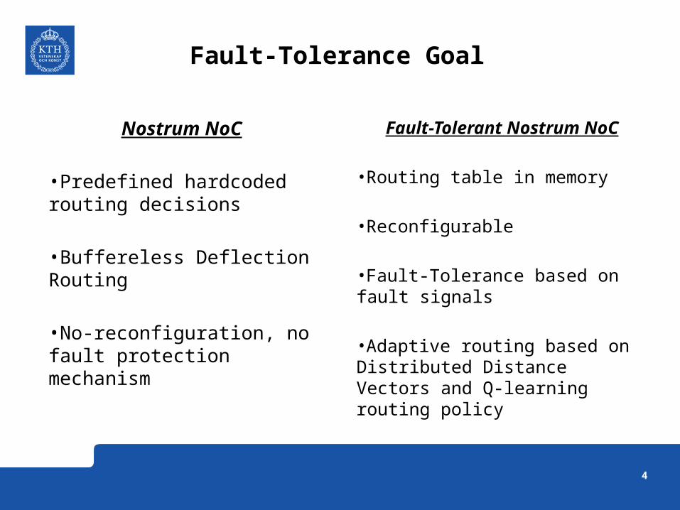
Fault-Tolerant Nostrum NoC
•Routing table in memory
•Reconfigurable
•Fault-Tolerance based on fault signals
•Adaptive routing based on Distributed Distance Vectors and Q-learning routing policy
Nostrum NoC
•Predefined hardcoded routing decisions
•Buffereless Deflection Routing
•No-reconfiguration, no fault protection mechanism
5
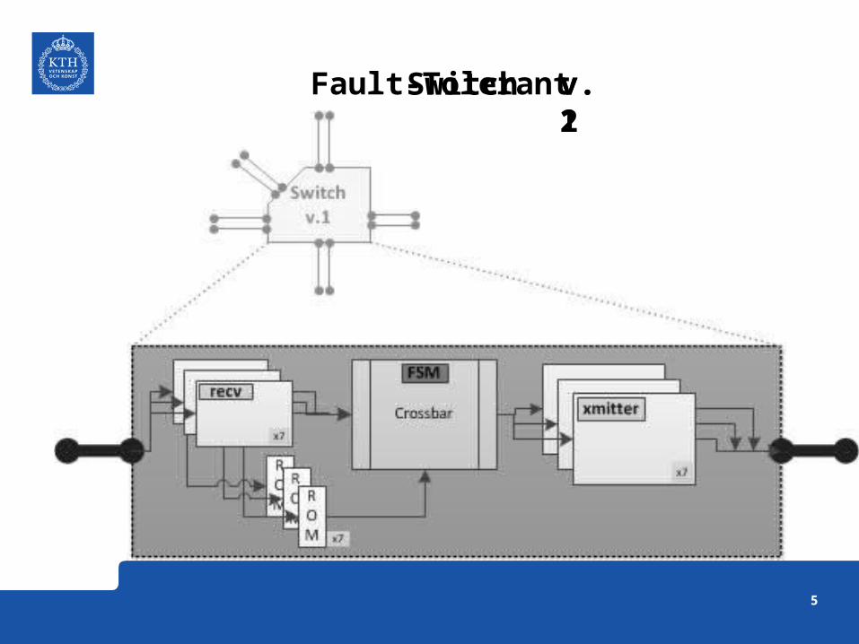
Fault-Tolerant v.1v.2Switch
6
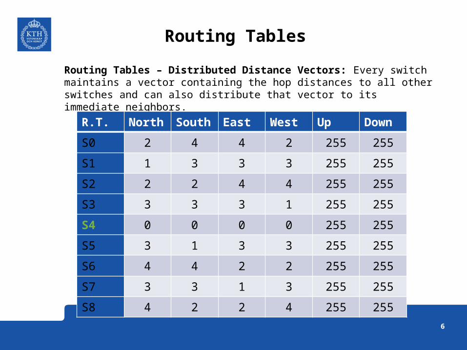
Routing Tables – Distributed Distance Vectors: Every switch maintains a vector containing the hop distances to all other switches and can also distribute that vector to its immediate neighbors.
Routing Tables
R.T. North South East West Up Down
S0 2 4 4 2 255 255
S1 1 3 3 3 255 255
S2 2 2 4 4 255 255
S3 3 3 3 1 255 255
S4 0 0 0 0 255 255
S5 3 1 3 3 255 255
S6 4 4 2 2 255 255
S7 3 3 1 3 255 255
S8 4 2 2 4 255 255
7
Q-learning Routing
Q-Routing algorithm: learns a routing policy and makes routing decisions using only local information about the number of "hops“ that a packet needs to travel to the destination node.
Q-Routing ProcedureSuppose that Qx(d, y) is the time needed for a packet to travel from node x to d through the node y. When node y receives the packet, it immediately transmits back to node x the estimated delivery time, for this packet, from node y to node d.

8
FSM of the Fault-Tolerant Switch
• 7 states FSM• Dual port memories for each pair of directions• The ‘update’ packet configure the routing tables in state 1,2
9
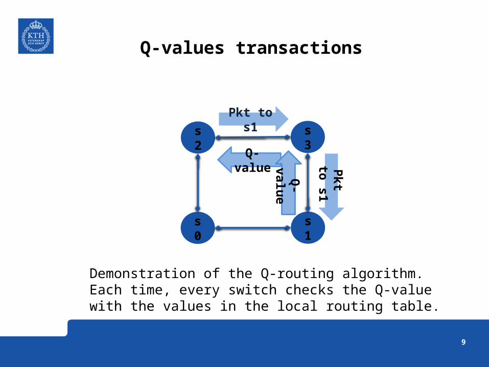
Q-values transactions
s2
s0 s1
s3
Pkt to s1
Q-value Pkt to
s1
Q-valu
e
Demonstration of the Q-routing algorithm. Each time, every switch checks the Q-value with the values in the local routing table.
10
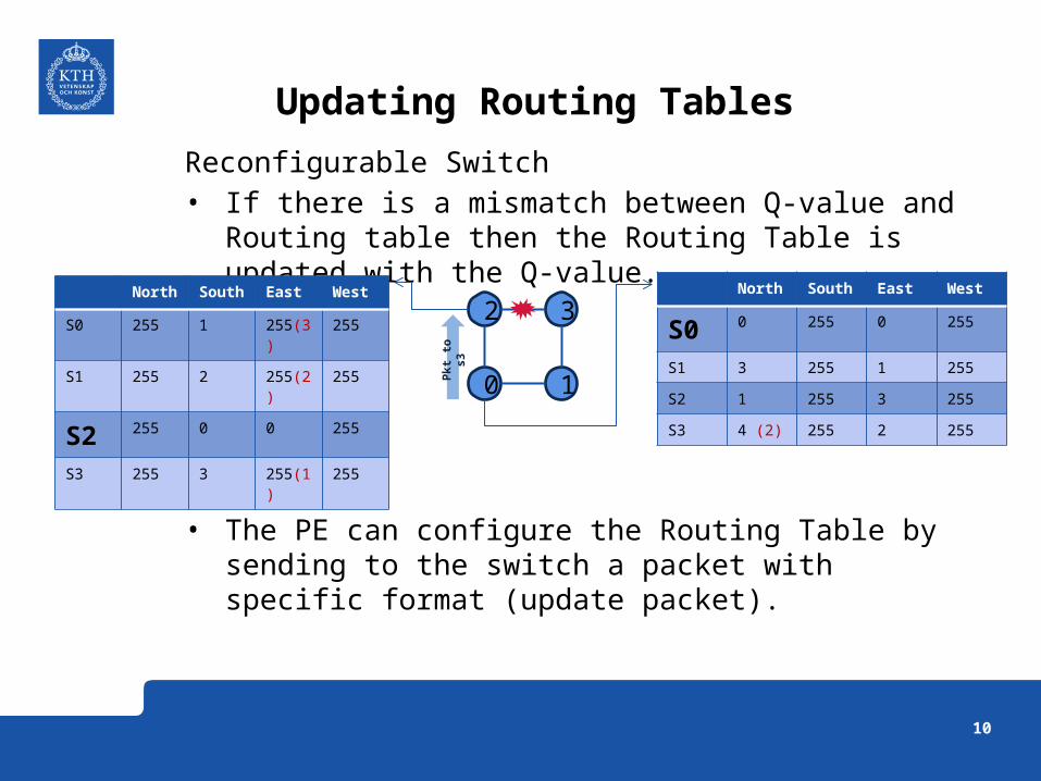
Reconfigurable Switch• If there is a mismatch between Q-value and Routing table
then the Routing Table is updated with the Q-value.
• The PE can configure the Routing Table by sending to the switch a packet with specific format (update packet).
Updating Routing Tables
North South East West
S0 0 255 0 255
S1 3 255 1 255
S2 1 255 3 255
S3 4 (2) 255 2 255
North South East West
S0 255 1 255(3) 255
S1 255 2 255(2) 255
S2 255 0 0 255
S3 255 3 255(1) 255
2 3
0 1Pkt
to
s3

11
Ref. Switch Switch v.1 Switch v.2
Total LEs 2,817 2,790 3,808
Total Registers 820 822 830
Memory - 4032 1152
Throughput 1pkt/4cc 1pkt/4cc 1pkt/7cc
Comparison
12
• A Fault Detection mechanism must be implemented in order to identify the failures on the links and trigger the fault signals.
• The beta Fault-Tolerant switch supports only NxN 2D-Mesh topologies. But it can be easily expanded to support 3D.
• The beta Fault-Tolerant switch doesn’t have the functionality to sent to the Resource routing information from its routing table.
Limitations
13
Future work
•The Q-learning algorithm has a learning period time. During that time the packet may be deflected to other directions away from the destination. It would be useful to investigate these timings under extreme traffic congestion.
•The Routing tables are the main overhead in terms of area. The number of the nodes in the network defines the number of entries in the memories. This could be reduce by dividing the network into regions. Then routing policy could be applied for inter-region routing and out-region routing.
•The Distributed Distance Vectors combined with a “soft internal channel” in the switch can provide a fixed delivery time of a packet.
– Set up priority flit– Priority list of input ports– List of output port associated with the priority list– If a packet arrives in one of the input port which is in the priority list and the
results from the Routing tables match with the list of output ports then serve it, else continue with the regular serving.

14
DEMO TIME 1/2
Modelsim Simulation 3x3 2D-Mesh
Starting point
Intermediate points
Ending point
15
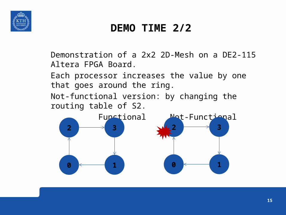
DEMO TIME 2/2
Demonstration of a 2x2 2D-Mesh on a DE2-115 Altera FPGA Board.
Each processor increases the value by one that goes around the ring.
Not-functional version: by changing the routing table of S2.
Functional Not-Functional
2
0 1
3 2
0 1
3

16
That was… The END…
Any question? Tackar

17
18
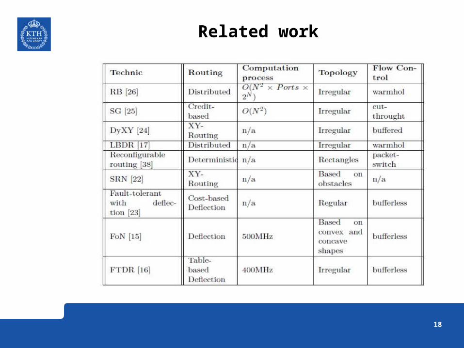
Related work