fax : (33) 01 60 05 70 37 european technical eta-02/0027 ... · or etag 001, annex c. installation:...
TRANSCRIPT

Centre Scientifique et
Technique du Bâtiment 84 avenue Jean Jaurès CHAMPS-SUR-MARNE F-77447 Marne-la-Vallée Cedex 2 Tél. : (33) 01 64 68 82 82 Fax : (33) 01 60 05 70 37
Member of
www.eota.eu
European Technical Assessment
ETA-02/0027 of 20/09/2017
English translation prepared by CSTB - Original version in French language
General Part
Nom commercial Trade name
Hilti Safety Anchor HSC-A(R) and HSC-I(R)
Famille de produit Product family
Cheville métallique en acier galvanisé ou inoxydable, à verrouillage de forme par auto ancrage, pour utilisation dans le béton : diamètres M6, M8, M10 et M12.
Self-cutting undercut anchor, made of galvanised steel or stainless steel, for use in concrete: sizes M6, M8, M10 and M12.
Titulaire Manufacturer
Hilti Corporation Feldkircherstrasse 100 FL-9494 Schaan Principality of Liechtenstein
Usine de fabrication Manufacturing plants
Hilti plants
Cette évaluation contient: This assessment contains
16 pages incluant 13 pages d’annexes qui font partie intégrante de cette évaluation 16 pages including 13 pages of annexes which form an integral part of this assessment
Base de l‘ETE Basis of ETA
DEE 330232-00-0601 “Ancrages mécaniques dans le béton” EAD 330232-00-0601 “Mechanical fasteners for use in concrete”
Cette évaluation remplace: This assessment replaces
ATE-0 2 / 0 0 2 7 délivrée le 20/09/2012 ETA-0 2 / 0 0 2 7 issued on 20/09/2012
Translations of this European Technical Assessment in other languages shall fully correspond to the original issued document and should be identified as such. Communication of this European Technical Assessment, including transmission by electronic means, shall be in full. However, partial reproduction may be made, with the written consent of the issuing Technical Assessment Body. Any partial reproduction has to be identified as such.

European technical assessment ETA - 0 2 / 0 0 2 7
English translation prepared by CSTB
Page 2 of 16 | 2 0 / 0 9 / 2 0 1 7
Specific Part
Technical description of the product
The Hilti Safety Anchor HSC-A(R) and HSC-I(R) anchors in the range of M6 to M12 is a self-cutting undercut anchor made of galvanised steel or stainless steel. The Hilti HSC anchor is available in four versions : an externally threaded carbon steel version (HSC-A), an internally threaded carbon steel version (HSC-I), an externally threaded stainless steel version (HSC-AR), an internally threaded stainless steel version (HSC-IR). It is placed into a hole drilled with a special stop drill bit and self-cutting undercut using a special setting tool. The nut is torque tightened to complete the fastening of the fixture. In the case of HSC-I and HSC-IR version, the fixture shall be anchored with a fastening screw or a threaded rod.
Specification of the intended use
The performances given in Section 3 are only valid if the anchor is used in compliance with the specifications and conditions given in Annexes B.
The provisions made in this European technical assessment are based on an assumed working life of the anchor of 50 years. The indications given on the working life cannot be interpreted as a guarantee given by the producer, but are to be regarded only as a means for choosing the right products in relation to the expected economically reasonable working life of the works.
Performance of the product
Mechanical resistance and stability (BWR 1)
Essential characteristic Performance
Characteristic tension resistance in case of static and quasi-static loading
See Annex C1
Characteristic shear resistance in case of static and quasi-static loading See Annex C2, C3
Displacements under tension loads in case of static and quasi-static loading
See Annex C4
Displacements under shear loads in case of static and quasi-static loading
See Annex C5
Safety in case of fire (BWR 2)
Essential characteristic Performance
Reaction to fire Anchorages satisfy requirements for Class A1
Hygiene, health and the environment (BWR 3)
Regarding dangerous substances contained in this European technical approval, there may be requirements applicable to the products falling within its scope (e.g. transposed European legislation and national laws, regulations and administrative provisions). In order to meet the provisions of the Construction Products Directive, these requirements need also to be complied with, when and where they apply.
Safety in use (BWR 4)
For Basic requirement Safety in use the same criteria are valid as for Basic Requirement Mechanical resistance and stability.
Protection against noise (BWR 5)
Not relevant.
Energy economy and heat retention (BWR 6)
Not relevant.

European technical assessment ETA - 0 2 / 0 0 2 7
English translation prepared by CSTB
Page 3 of 16 | 2 0 / 0 9 / 2 0 1 7
Sustainable use of natural resources (BWR 7)
For the sustainable use of natural resources no performance was determined for this product.
General aspects relating to fitness for use
Durability and Serviceability are only ensured if the specifications of intended use according to Annex B1 are kept.
Assessment and verification of constancy of performance (AVCP)
According to the Decision 96/582/EC of the European Commission1, as amended, the system of assessment and verification of constancy of performance (see Annex V to Regulation (EU) No 305/2011) given in the following table apply.
Product Intended use Level or Class System
Metal anchors for use in concrete
For fixing and/or supporting to concrete, structural elements (which contributes to the stability of the works) or heavy units
― 1
Technical details necessary for the implementation of the AVCP system
Technical details necessary for the implementation of the Assessment and verification of constancy of performance (AVCP) system are laid down in the control plan deposited at Centre Scientifique et Technique du Bâtiment.
The manufacturer shall, on the basis of a contract, involve a notified body approved in the field of anchors for issuing the certificate of conformity CE based on the control plan.
Issued in Marne La Vallée on 2 0 / 0 9 / 2 0 1 7 by
Charles Baloche The original French version is signed
Directeur technique
1 Official Journal of the European Communities L 254 of 08.10.1996

European technical assessment ETA - 0 2 / 0 0 2 7
English translation prepared by CSTB
Page 4 of 16 | 2 0 / 0 9 / 2 0 1 7
Annex A1
Hilti Safety Anchor HSC-A(R) and HSC-I(R)
Product description Installed condition
Installed condition:
Figure A1:
HSC-A(R) safety anchor (externally threaded version)
Figure A2:
HSC-I(R) safety anchor (internally threaded version)

European technical assessment ETA - 0 2 / 0 0 2 7
English translation prepared by CSTB
Page 5 of 16 | 2 0 / 0 9 / 2 0 1 7
Annex A2
Hilti Safety Anchor HSC-A(R) and HSC-I(R)
Product description
Product description :
HSC(-R) safety anchor (externally and internally threaded version)

European technical assessment ETA - 0 2 / 0 0 2 7
English translation prepared by CSTB
Page 6 of 16 | 2 0 / 0 9 / 2 0 1 7
Annex A3
Hilti Safety Anchor HSC-A(R) and HSC-I(R)
Product description Materials
Table A1: Materials
Designation Material
HSC made of zinc coated steel
Cone bolt with external thread Strength class 8.8, electroplated zinc coated ≥ 5µm, Rupture elongation (l0 = 5d) > 8%
Cone bolt with internal thread Strength class 8.8, electroplated zinc coated ≥ 5µm Rupture elongation (l0 = 5d) > 8%
Expansion sleeve Electroplated zinc coated ≥ 5µm
Washer Electroplated zinc coated ≥ 5µm
Hexagon nut Strength class 8, electroplated zinc coated ≥ 5µm
HSC-R made of stainless steel
Cone bolt with external thread A4-70, Stainless steel 1.4401, 1.4571 EN 10088-1:2014 Rupture elongation (l0 = 5d) > 8%
Cone bolt with internal thread A4-70, Stainless steel 1.4401, 1.4571 EN 10088-1:2014 Rupture elongation (l0 = 5d) > 8%
Expansion sleeve Stainless steel 1.4401, 1.4571 EN 10088-1:2014
Washer Stainless steel 1.4401, 1.4571 EN 10088-1:2014
Hexagon nut A4-70, Stainless steel 1.4401, 1.4571 EN 10088-1:2014

European technical assessment ETA - 0 2 / 0 0 2 7
English translation prepared by CSTB
Page 7 of 16 | 2 0 / 0 9 / 2 0 1 7
Annex A4
Hilti Safety Anchor HSC-A(R) and HSC-I(R)
Product description Dimensions
Table A2: Dimensions externally threaded version HSC-A(R)
Size M8 x 40 M10 x 40 M8 x 50 M12 x 60
Thread size M8 M10 M8 M12
Diameter of cone bolt b [mm] 13,5 15,5 13,5 17,5
Length of expansion sleeve ls [mm] 40,8 40,8 50,8 60,8
Diameter of expansion sleeve d [mm] 13,5 15,5 13,5 17,5
Diameter of washer e [mm] 16 20 16 24
Table A3: Dimensions internally threaded version HSC-I(R)
Size M6 x 40 M8 x 40 M10 x 50 M10 x 60 M12 x 60
Thread size M6 M8 M10 M10 M12
Length of cone bolt lb [mm] 43,3 43,3 54,8 64,8 64,8
Diameter of cone bolt b [mm] 13,5 15,5 17,5 17,5 19,5
Length of expansion sleeve ls [mm] 40,8 40,8 50,8 60,8 60,8
Diameter of expansion sleeve d [mm] 13,5 15,5 17,5 17,5 19,5
European technical assessment ETA - 0 2 / 0 0 2 7
English translation prepared by CSTB
Page 8 of 16 | 2 0 / 0 9 / 2 0 1 7
Annex B1
Hilti Safety Anchor HSC-A(R) and HSC-I(R)
Intended use Specifications
Specifications of intended use
Anchorages subject to:
Static and quasi-static loading.
Base materials:
Reinforced or unreinforced normal weight concrete according to EN 206:2013. Strength classes C20/25 to C50/60 according to EN 206:2013. Cracked concrete and non-cracked concrete.
Use conditions (Environmental conditions):
Structures subject to dry internal conditions (zinc coated steel, stainless steel).
Structures subject to subject to external atmospheric exposure (including industrial and marine environment), and to permanently damp internal conditions, if no particular aggressive conditions exist (stainless steel). Note: Such particular aggressive conditions are e.g. permanent, alternating immersion in seawater or the splash zone of seawater, chloride atmosphere of indoor swimming pools or atmosphere with extreme chemical pollution (e.g. in desulphurization plants or road tunnels where de-icing products are used).
Design:
Anchorages are designed under the responsibility of an engineer experienced in anchorages and concrete work.
Verifiable calculation notes and drawings are prepared taking account of the loads to be anchored. The position of the anchor is indicated on the design drawings (e. g. position of the anchor relative to reinforcement or to supports, etc.).
Anchorages under static or quasi-static loading are designed in accordance with: Technical Report TR 055 “Design of fastenings based on EAD 33.232-00.601” and FprEN 1992-4 or ETAG 001, Annex C.
Installation:
Anchor installation carried out by appropriately qualified personnel and under the supervision of the person responsible for technical matters of the site.
Anchor installation in accordance with the manufacturer’s specifications given in Annex B1 to B4. In case of aborted hole, drilling of new hole at a minimum distance of twice the depth of the aborted hole,
or smaller distance provided the aborted drill hole is filled with high strength mortar and no shear or oblique tension loads in the direction of aborted hole.
European technical assessment ETA - 0 2 / 0 0 2 7
English translation prepared by CSTB
Page 9 of 16 | 2 0 / 0 9 / 2 0 1 7
Annex B2
Hilti Safety Anchor HSC-A(R) and HSC-I(R)
Intended use Installation parameters
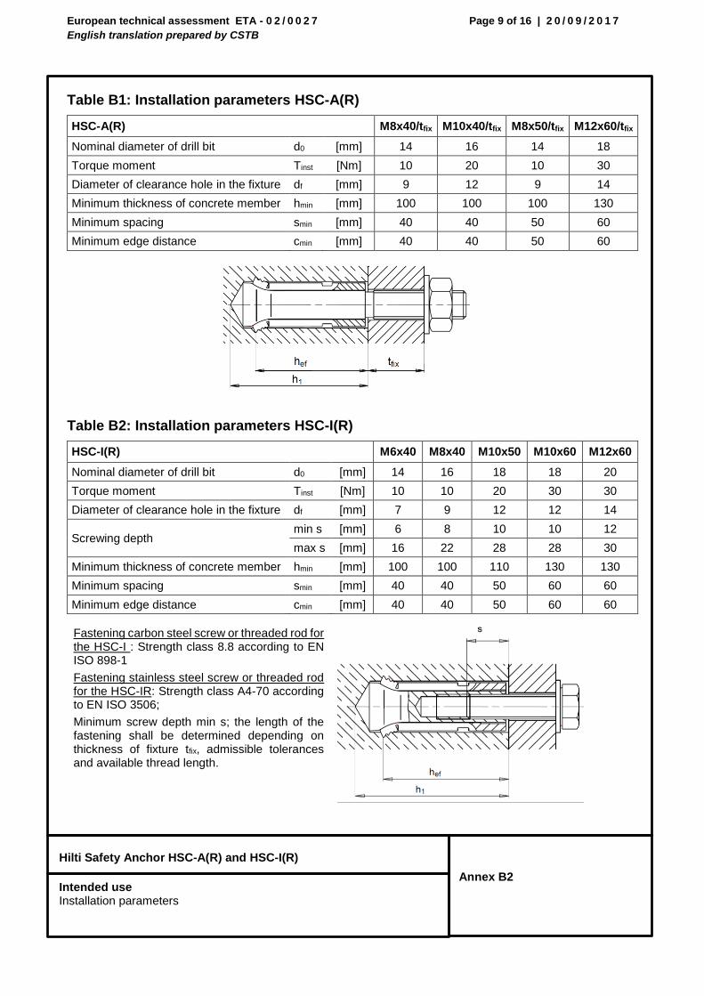
Table B1: Installation parameters HSC-A(R)
Table B2: Installation parameters HSC-I(R)
Fastening carbon steel screw or threaded rod for the HSC-I : Strength class 8.8 according to EN ISO 898-1
Fastening stainless steel screw or threaded rod for the HSC-IR: Strength class A4-70 according to EN ISO 3506;
Minimum screw depth min s; the length of the fastening shall be determined depending on thickness of fixture tfix, admissible tolerances and available thread length.
HSC-A(R) M8x40/tfix M10x40/tfix M8x50/tfix M12x60/tfix
Nominal diameter of drill bit d0 [mm] 14 16 14 18
Torque moment Tinst [Nm] 10 20 10 30
Diameter of clearance hole in the fixture df [mm] 9 12 9 14
Minimum thickness of concrete member hmin [mm] 100 100 100 130
Minimum spacing smin [mm] 40 40 50 60
Minimum edge distance cmin [mm] 40 40 50 60
HSC-I(R) M6x40 M8x40 M10x50 M10x60 M12x60
Nominal diameter of drill bit d0 [mm] 14 16 18 18 20
Torque moment Tinst [Nm] 10 10 20 30 30
Diameter of clearance hole in the fixture df [mm] 7 9 12 12 14
Screwing depth min s [mm] 6 8 10 10 12
max s [mm] 16 22 28 28 30
Minimum thickness of concrete member hmin [mm] 100 100 110 130 130
Minimum spacing smin [mm] 40 40 50 60 60
Minimum edge distance cmin [mm] 40 40 50 60 60

European technical assessment ETA - 0 2 / 0 0 2 7
English translation prepared by CSTB
Page 10 of 16 | 2 0 / 0 9 / 2 0 1 7
Annex B3
Hilti Safety Anchor HSC-A(R) and HSC-I(R)
Intended use Drilling and setting tools
Table B3: Parameters of drilling and setting tools HSC-A(R)
HSC-A(R) M8x40/tfix M10x40/tfix M8x50/tfix M12x60/tfix
Nominal diameter of drill bit d0 [mm] 14 16 14 18
Drill bit length t [mm] 46 46,5 56 68
Stop drill bit
HSC-B
B14 x 40 B16 x 40 B14 x 50 B18 x 60
Setting tool
HSC-MW
HSC-MW14 HSC-MW16 HSC-MW14 HSC-MW18
Table B4: Parameters of drilling and setting tools HSC-I(R)
HSC-I(R) M6x40 M8x40 M10x50 M10x60 M12x60
Nominal diameter of drill bit
d0 [mm] 14 16 18 18 20
Drill bit length t [mm] 46 46,5 56 68 68,5
Stop drill bit
HSC-B B14 x 40 B16 x 40 B18 x 50 B18 x 60 B20 x 60
Setting tool
HSC-MW HSC-MW14 HSC-MW16 HSC-MW18 HSC-MW18 HSC-MW20
Insert tool
HSC-EW HSC-EW14 HSC-EW16 HSC-EW18 HSC-EW18 HSC-EW20
Drilling and setting tools
Stop drill bit HSC-B
Setting tools
HSC-A(R) Setting tool HSC-MW
HSC-I(R) Insert tool HSC-EW Setting tool HSC-MW

European technical assessment ETA - 0 2 / 0 0 2 7
English translation prepared by CSTB
Page 11 of 16 | 2 0 / 0 9 / 2 0 1 7
Annex B4
Hilti Safety Anchor HSC-A(R) and HSC-I(R)
Intended use Installation instructions
Installation instruction
Hole drilling and cleaning
HSC-A(R) and HSC-I(R): Hole drilling with stop drill bit HSC-B, manual cleaning.
Anchor setting
a) HSC-A(R) b) HSC-I(R)
Check setting
Anchor torqueing

European technical assessment ETA - 0 2 / 0 0 2 7
English translation prepared by CSTB
Page 12 of 16 | 2 0 / 0 9 / 2 0 1 7
Annex C1
Hilti Safety Anchor HSC-A(R) and HSC-I(R)
Performances Characteristic resistance under tension load in concrete
Table C1: Characteristic resistance for HSC-A(R) under tension load in concrete
1) In absence of national regulations. 2) Parameter according to FprEN 1992-4 3) Parameter according to ETAG001, Annex C.
Table C2: Characteristic resistance for HSC-I(R) under tension load in concrete
1) In absence of national regulations. 2) Parameter according to FprEN 1992-4 3) Parameter according to ETAG001, Annex C.
M8x40 M10x40 M8x50 M12x60
Steel failure HSC-A
Characteristic resistance NRk,s [kN] 29,3 46,4 29,3 67,4
Partial safety yhjuyhjyjfactorfactor
Ms1) [-] 1,50
Steel failure HSC-AR
Characteristic resistance NRk,s [kN] 25,6 40,6 25,6 59,0
Partial safety yhjuyhjyjfactorfactor
Ms1) [-] 1,87
Pull-out failure Not governing
Concrete cone and splitting failure
Effective anchorage depth hef [mm] 40 40 50 60
Factor for Cracked k1 = kcr [-] 7,72) / 7,23)
Non-cracked k1 = kucr [-] 11,02) / 10,23)
Spacing scr,N [mm] 120 120 150 180
Edge distance ccr,N [mm] 60 60 75 90
Spacing scr,sp [mm] 130 120 170 180
Edge distance ccr,sp [mm] 65 60 85 90
Partial safety factor 23) = inst [-] 1,0
M6x40 M8x40 M10x50 M10x60 M12x60
Steel failure HSC-I
Characteristic resistance NRk,s [kN] 16,1 24,4 30,3 30,3 36,5
Partial safety yhjuyhjyjfactorfactor
Ms1) [-] 1,50
Steel failure HSC-I(R)
Characteristic resistance NRk,s [kN] 14,1 21,4 26,5 26,5 31,9
Partial safety yhjuyhjyjfactorfactor
Ms1) [-] 1,87
Pull-out failure Not governing
Concrete cone and splitting failure
Effective anchorage depth hef [mm] 40 40 50 60 60
Factor for Cracked k1 = kcr [-] 7,72) / 7,23)
Non-cracked k1 = kucr [-] 11,02) / 10,23)
Spacing scr,N [mm] 120 120 150 180 180
Edge distance ccr,N [mm] 60 60 75 90 90
Spacing scr,sp [mm] 130 120 170 180 180
Edge distance ccr,sp [mm] 65 60 85 90 90
Partial safety factor 23) = inst [-] 1,0

European technical assessment ETA - 0 2 / 0 0 2 7
English translation prepared by CSTB
Page 13 of 16 | 2 0 / 0 9 / 2 0 1 7
Annex C2
Hilti Safety Anchor HSC-A(R) and HSC-I(R)
Performances Characteristic resistance under shear load in concrete
Table C3: Characteristic resistance for HSC-A(R) under shear load in concrete
1) In absence of national regulations. 2) Parameter according to ETAG001, Annex C.
M8x40 M10x40 M8x50 M12x60
Steel failure without lever arm
Characteristic resistance HSC-A VRk,s [kN] 14,6 23,2 14,6 33,7
Partial safety factor Ms,V1) [-] 1,25
Characteristic resistance HSC-AR VRk,s [kN] 12,8 20,3 12,8 29,5
Partial safety factor Ms1) [-] 1,56
Ductility factor k2 = k7 1,0
Steel failure with lever arm
Characteristic resistance HSC-A M0Rks [Nm] 30 60 30 105
Partial safety factor Ms,V1) [-] 1,25
Characteristic resistance HSC-AR M0Rks [Nm] 26 52 26 92
Partial safety factor Ms,V1) [-] 1,56
Concrete pryout failure
Pry-out factor k8 = k2) 2 2 2 2
Installation safety factor 22) = inst [-] 1,0
Concrete edge failure
Effective length of anchor in shear loading
lf [mm] 40 40 50 60
External diameter of anchor dnom [mm] 14 16 14 18
Installation safety factor 22) = inst [-] 1,0

European technical assessment ETA - 0 2 / 0 0 2 7
English translation prepared by CSTB
Page 14 of 16 | 2 0 / 0 9 / 2 0 1 7
Annex C3
Hilti Safety Anchor HSC-A(R) and HSC-I(R)
Performances Characteristic resistance under shear load in concrete
Table C4: Characteristic resistance for HSC-I(R) under shear load in concrete
1) In absence of national regulations. 2) Parameter according to ETAG001, Annex C.
M6x40 M8x40 M10x50 M10x60 M12x60
Steel failure without lever arm
Characteristic resistance HSC-I VRk,s [kN] 8,0 12,2 15,2 15,2 18,2
Partial safety factor Ms,V1) [-] 1,25
Characteristic resistance HSC-IR VRk,s [kN] 7,0 10,7 13,3 13,3 16,0
Partial safety factor Ms,V1) [-] 1,56
Ductility factor k2 = k7 1,0
Steel failure with lever arm
Characteristic resistance HSC-I M0Rks [Nm] 12 30 60 60 105
Partial safety factor Ms,V1) [-] 1,25
Characteristic resistance HSC-IR M0Rks [Nm] 11 26 52 52 92
Partial safety factor Ms,V1) [-] 1,56
Concrete pryout failure
Pry-out factor k3 = k8 = k2) 2 2 2 2 2
Installation safety factor 22) = inst [-] 1,0
Concrete edge failure
Effective length of anchor in shear loading
lf [mm] 40 40 50 60 60
External diameter of anchor dnom [mm] 14 16 18 18 20
Installation safety factor 22) = inst [-] 1,0

European technical assessment ETA - 0 2 / 0 0 2 7
English translation prepared by CSTB
Page 15 of 16 | 2 0 / 0 9 / 2 0 1 7
Annex C4
Hilti Safety Anchor HSC-A(R) and HSC-I(R)
Performances Displacements under tension load
Table C5: Displacements for HSC-A(R) under tension loads in case of static and quasi-static loading
HSC-A carbon steel M8x40 M10x40 M8x50 M12x60
Tension load in non-cracked concrete N [kN] 5,1 5,1 7,1 9,3
Displacement N0 [mm] 0,1 0,1 0,1 0,1
N [mm] 0,2 0,2 0,2 0,2
Tension load in cracked concrete N [kN] 3,6 3,6 5,1 6,6
Displacement N0 [mm] 0,2 0,2 0,3 0,4
N [mm] 0,7 0,7 0,6 0,4
HSC-AR stainless steel
Tension load in non-cracked concrete N [kN] 5,1 5,1 7,1 9,3
Displacement N0 [mm] 0,1 0,1 0,1 0,2
N [mm] 0,3 0,3 0,3 0,3
Tension load in cracked concrete N [kN] 3,6 3,6 5,1 6,6
Displacement N0 [mm] 0,4 0,4 0,4 1,0
N [mm] 0,9 1,0 0,9 1,0
Table C6: Displacements for HSC-I(R) under tension loads in case of static and quasi-static loading
HSC-I carbon steel M6x40 M8x40 M10x50 M10x60 M12x60
Tension load in non-cracked concrete N [kN] 5,1 5,1 7,1 9,3 9,3
Displacement N0 [mm] 0,1 0,1 0,1 0,1 0,1
N [mm] 0,2 0,2 0,2 0,2 0,2
Tension load in cracked concrete N [kN] 3,6 3,6 5,1 6,6 6,6
Displacement N0 [mm] 0,2 0,2 0,3 0,4 0,2
N [mm] 0,7 0,7 0,6 0,4 0,7
HSC-IR stainless steel
Tension load in non-cracked concrete N [kN] 5,1 5,1 7,1 9,3 9,3
Displacement N0 [mm] 0,1 0,1 0,1 0,2 0,2
N [mm] 0,3 0,3 0,3 0,3 0,3
Tension load in cracked concrete N [kN] 3,6 3,6 5,1 6,6 6,6
Displacement N0 [mm] 0,4 0,4 0,5 0,5 1,0
N [mm] 0,9 1,0 1,2 0,9 1,0

European technical assessment ETA - 0 2 / 0 0 2 7
English translation prepared by CSTB
Page 16 of 16 | 2 0 / 0 9 / 2 0 1 7
Annex C5
Hilti Safety Anchor HSC-A(R) and HSC-I(R)
Performances Displacements under shear load
Table C7: Displacements for HSC-A(R) under shear loads in case of static and quasi-static loading
1) Additional displacement due to annular gap between anchor and fixture is to be taken into account.
Table C8: Displacements for HSC-I(R) under shear loads in case of static and quasi-static loading
1) Additional displacement due to annular gap between anchor and fixture is to be taken into account.
HSC-A(R) carbon steel and stainless steel
M8x40/15 M10x40/20 M8x50/15 M12x60/20
Shear load in cracked and non-cracked concrete
[kN] 8,4 13,3 8,4 19,3
Displacement1) V0 [mm] 3,0 3,0 2,8 3,0
V [mm] 4,5 4,5 4,3 4,5
HSC-I(R) carbon steel and stainless steel
M6x40 M8x40 M10x50 M10x60 M12x60
Shear load in cracked and non-cracked concrete
[kN] 4,6 7,0 8,7 8,7 10,4
Displacement1) V0 [mm] 3,0 3,0 2,8 3,0 3,0
V [mm] 4,5 4,5 4,3 4,5 4,5