fcc doc test report - panasonic.com · the sample was received on sep 13, 2015 and the testing was...
TRANSCRIPT
CERPASS TECHNOLOGY CORP. Report No.:SEFD1605056
Cerpass Technology Corp. Issued Date May 12, 2016
Report format Revision 01 Page No. : 1 of 31
FCC DOC TEST REPORT
According to
47 CFR, Part 2, Part 15, CISPR PUB. 22
ICES 003 Issue 6
Applicant : Panasonic India Pvt. Ltd.
Address : 6th Floor, "SPIC BUILDING" Annexe, No. 88, Mount Road, Guindy, Chennai - 600 032.
Equipment : Network Bullet Camera
Model No. : PI-SPW201L,PI-SPW401L
Trade Name : Panasonic
I HEREBY CERTIFY THAT :
The sample was received on Sep 13, 2015 and the testing was carried out on Sep 26, 2015 at Cerpass
Technology Corp. The test result refers exclusively to the test presented test model / sample. Without
written approval of Cerpass Technology Corp., the test report shall not be reproduced except in full.
Approved by:
Ray Chou
EMC/RF B.U. Assistant Manager
CERPASS TECHNOLOGY CORP. Report No.:SEFD1605056
Cerpass Technology Corp. Issued Date May 12, 2016
Report format Revision 01 Page No. : 2 of 31
FCC TEST REPORT Issued by:
Cerpass Technology Co.,Ltd
No.10, Lane 2, Lianfu Street, Luzhu Township, Taoyuan County 33848, Taiwan(R.O.C.)
Tel: 886-3-322-6888
Fax: 886-3-322-6881
The test record, data evaluation & Equipment. Under Test configurations represented herein are true and accurate accounts of the measurements of the samples EMC characteristics under the conditions specified in this report.
Laboratory Accreditation:
Cerpass Technology Corporation Test Laboratory
NVLAP LAB Code: 200954-0
TAF LAB Code: 1439
CERPASS TECHNOLOGY CORP. Report No.:SEFD1605056
Cerpass Technology Corp. Issued Date May 12, 2016
Report format Revision 01 Page No. : 3 of 31
Contents
1. Summary of Test Procedure and Test Result ...........................................................................................5
1.1. Applicable Standards ........................................................................................................................5
2. Test Configuration of Equipment under Test ............................................................................................6
2.1. Manufacturer.....................................................................................................................................6
2.2. Feature of Equipment under Test .....................................................................................................6
2.3. Test Manner ......................................................................................................................................6
2.4. Description of Test System ...............................................................................................................7
2.5. General Information of Test ..............................................................................................................8
2.6. Measurement Uncertainty ................................................................................................................8
3. Test of Conducted Emission ......................................................................................................................9
3.1. Test Limit ...........................................................................................................................................9
3.2. Test Procedures ................................................................................................................................9
3.3. Typical test Setup .......................................................................................................................... 10
3.4. Measurement equipment ............................................................................................................... 10
3.5. Test Result and Data ...................................................................................................................... 11
3.6. Test Photographs ........................................................................................................................... 13
4. Test of Radiated Emission ....................................................................................................................... 14
4.1. Test Limit ........................................................................................................................................ 14
4.2. Test Procedures ............................................................................................................................. 15
4.3. Typical test Setup .......................................................................................................................... 17
4.4. Measurement equipment ............................................................................................................... 18
4.5. Test Result and Data (30MHz ~ 1000MHz) ................................................................................... 19
4.6. Test Result and Data (1000MHz ~ 18000MHz) ............................................................................. 23
4.7. Test Photographs (30MHz ~ 1000MHz) ........................................................................................ 27
4.8. Test Photographs (1000MHz ~ 18000MHz) .................................................................................. 28
5. Photographs of EUT ................................................................................................................................. 29
CERPASS TECHNOLOGY CORP. Report No.:SEFD1605056
Cerpass Technology Corp. Issued Date May 12, 2016
Report format Revision 01 Page No. : 4 of 31
History of this test report
� ORIGINAL.
� Additional attachment as following record:
Report No Version Date Description
SEFD1605056 Rev 01 May 12, 2016 Initial Issue
CERPASS TECHNOLOGY CORP. Report No.:SEFD1605056
Cerpass Technology Corp. Issued Date May 12, 2016
Report format Revision 01 Page No. : 5 of 31
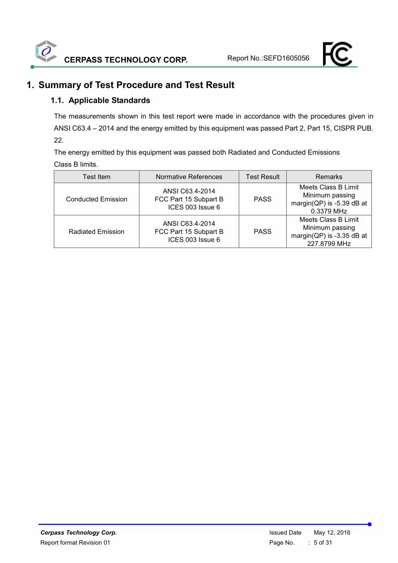
1. Summary of Test Procedure and Test Result
1.1. Applicable Standards
The measurements shown in this test report were made in accordance with the procedures given in
ANSI C63.4 – 2014 and the energy emitted by this equipment was passed Part 2, Part 15, CISPR PUB.
22.
The energy emitted by this equipment was passed both Radiated and Conducted Emissions
Class B limits.
Test Item Normative References Test Result Remarks
Conducted Emission
ANSI C63.4-2014
FCC Part 15 Subpart B
ICES 003 Issue 6
PASS
Meets Class B Limit
Minimum passing
margin(QP) is -5.39 dB at
0.3379 MHz
Radiated Emission
ANSI C63.4-2014
FCC Part 15 Subpart B
ICES 003 Issue 6
PASS
Meets Class B Limit
Minimum passing
margin(QP) is -3.35 dB at
227.8799 MHz
CERPASS TECHNOLOGY CORP. Report No.:SEFD1605056
Cerpass Technology Corp. Issued Date May 12, 2016
Report format Revision 01 Page No. : 6 of 31
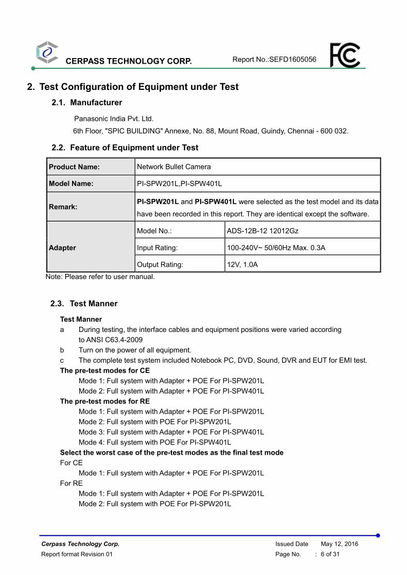
2. Test Configuration of Equipment under Test
2.1. Manufacturer
Panasonic India Pvt. Ltd.
6th Floor, "SPIC BUILDING" Annexe, No. 88, Mount Road, Guindy, Chennai - 600 032.
2.2. Feature of Equipment under Test
Product Name: Network Bullet Camera
Model Name: PI-SPW201L,PI-SPW401L
Remark: PI-SPW201L and PI-SPW401L were selected as the test model and its data
have been recorded in this report. They are identical except the software.
Adapter
Model No.: ADS-12B-12 12012Gz
Input Rating: 100-240V~ 50/60Hz Max. 0.3A
Output Rating: 12V, 1.0A
Note: Please refer to user manual.
2.3. Test Manner
Test Manner
a During testing, the interface cables and equipment positions were varied according
to ANSI C63.4-2009
b Turn on the power of all equipment.
c The complete test system included Notebook PC, DVD, Sound, DVR and EUT for EMI test.
The pre-test modes for CE
Mode 1: Full system with Adapter + POE For PI-SPW201L
Mode 2: Full system with Adapter + POE For PI-SPW401L
The pre-test modes for RE
Mode 1: Full system with Adapter + POE For PI-SPW201L
Mode 2: Full system with POE For PI-SPW201L
Mode 3: Full system with Adapter + POE For PI-SPW401L
Mode 4: Full system with POE For PI-SPW401L
Select the worst case of the pre-test modes as the final test mode
For CE
Mode 1: Full system with Adapter + POE For PI-SPW201L
For RE
Mode 1: Full system with Adapter + POE For PI-SPW201L
Mode 2: Full system with POE For PI-SPW201L
CERPASS TECHNOLOGY CORP. Report No.:SEFD1605056
Cerpass Technology Corp. Issued Date May 12, 2016
Report format Revision 01 Page No. : 7 of 31
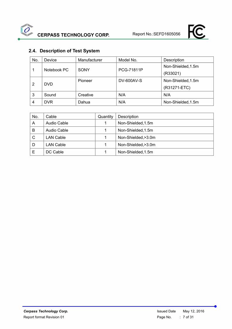
2.4. Description of Test System
No. Device Manufacturer Model No. Description
1 Notebook PC SONY PCG-71811P Non-Shielded,1.5m
(R33021)
2 DVD Pioneer DV-600AV-S Non-Shielded,1.5m
(R31271-ETC)
3 Sound Creative N/A N/A
4 DVR Dahua N/A Non-Shielded,1.5m
No. Cable Quantity Description
A Audio Cable 1 Non-Shielded,1.5m
B Audio Cable 1 Non-Shielded,1.5m
C LAN Cable 1 Non-Shielded,>3.0m
D LAN Cable 1 Non-Shielded,>3.0m
E DC Cable 1 Non-Shielded,1.5m
CERPASS TECHNOLOGY CORP. Report No.:SEFD1605056
Cerpass Technology Corp. Issued Date May 12, 2016
Report format Revision 01 Page No. : 8 of 31
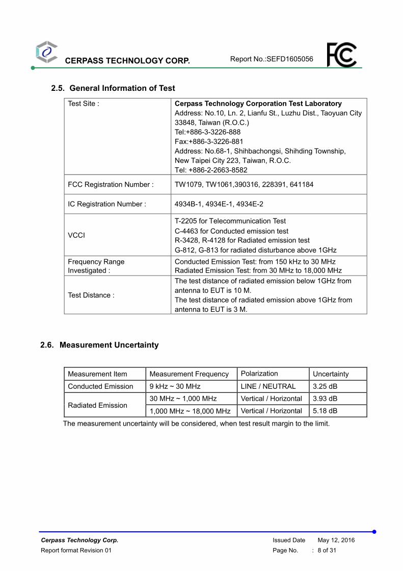
2.5. General Information of Test
Test Site : Cerpass Technology Corporation Test Laboratory
Address: No.10, Ln. 2, Lianfu St., Luzhu Dist., Taoyuan City
33848, Taiwan (R.O.C.)
Tel:+886-3-3226-888
Fax:+886-3-3226-881
Address: No.68-1, Shihbachongsi, Shihding Township,
New Taipei City 223, Taiwan, R.O.C.
Tel: +886-2-2663-8582
FCC Registration Number : TW1079, TW1061,390316, 228391, 641184
IC Registration Number : 4934B-1, 4934E-1, 4934E-2
VCCI
T-2205 for Telecommunication Test
C-4463 for Conducted emission test
R-3428, R-4128 for Radiated emission test
G-812, G-813 for radiated disturbance above 1GHz
Frequency Range
Investigated :
Conducted Emission Test: from 150 kHz to 30 MHz
Radiated Emission Test: from 30 MHz to 18,000 MHz
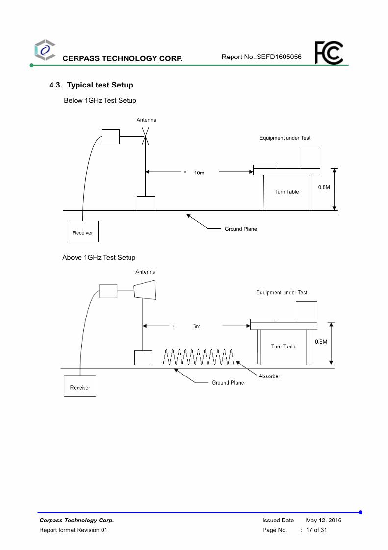
Test Distance :
The test distance of radiated emission below 1GHz from
antenna to EUT is 10 M.
The test distance of radiated emission above 1GHz from
antenna to EUT is 3 M.
2.6. Measurement Uncertainty
Measurement Item Measurement Frequency Polarization Uncertainty
Conducted Emission 9 kHz ~ 30 MHz LINE / NEUTRAL 3.25 dB
Radiated Emission 30 MHz ~ 1,000 MHz Vertical / Horizontal 3.93 dB
1,000 MHz ~ 18,000 MHz Vertical / Horizontal 5.18 dB
The measurement uncertainty will be considered, when test result margin to the limit.
CERPASS TECHNOLOGY CORP. Report No.:SEFD1605056
Cerpass Technology Corp. Issued Date May 12, 2016
Report format Revision 01 Page No. : 9 of 31
3. Test of Conducted Emission
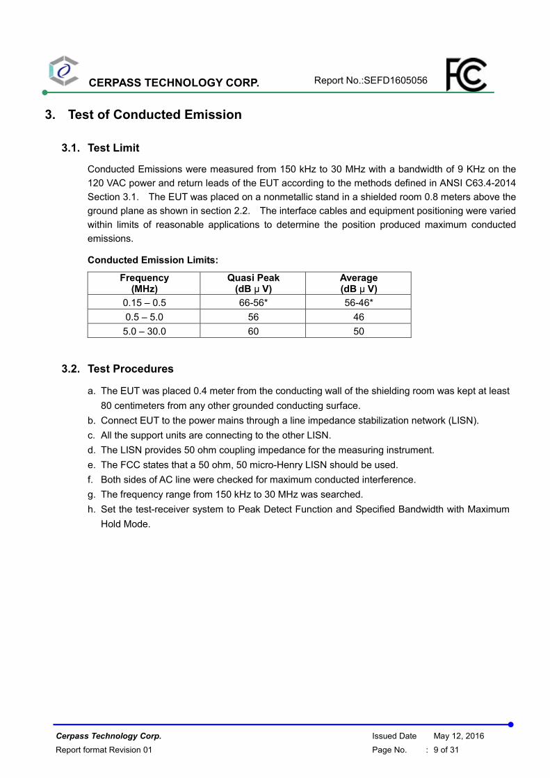
3.1. Test Limit
Conducted Emissions were measured from 150 kHz to 30 MHz with a bandwidth of 9 KHz on the
120 VAC power and return leads of the EUT according to the methods defined in ANSI C63.4-2014
Section 3.1. The EUT was placed on a nonmetallic stand in a shielded room 0.8 meters above the
ground plane as shown in section 2.2. The interface cables and equipment positioning were varied
within limits of reasonable applications to determine the position produced maximum conducted
emissions.
Conducted Emission Limits:
Frequency (MHz)
Quasi Peak (dB µ V)
Average (dB µ V)
0.15 – 0.5 66-56* 56-46*
0.5 – 5.0 56 46
5.0 – 30.0 60 50
3.2. Test Procedures
a. The EUT was placed 0.4 meter from the conducting wall of the shielding room was kept at least
80 centimeters from any other grounded conducting surface.
b. Connect EUT to the power mains through a line impedance stabilization network (LISN).
c. All the support units are connecting to the other LISN.
d. The LISN provides 50 ohm coupling impedance for the measuring instrument.
e. The FCC states that a 50 ohm, 50 micro-Henry LISN should be used.
f. Both sides of AC line were checked for maximum conducted interference.
g. The frequency range from 150 kHz to 30 MHz was searched.
h. Set the test-receiver system to Peak Detect Function and Specified Bandwidth with Maximum
Hold Mode.
CERPASS TECHNOLOGY CORP. Report No.:SEFD1605056
Cerpass Technology Corp. Issued Date May 12, 2016
Report format Revision 01 Page No. : 10 of 31
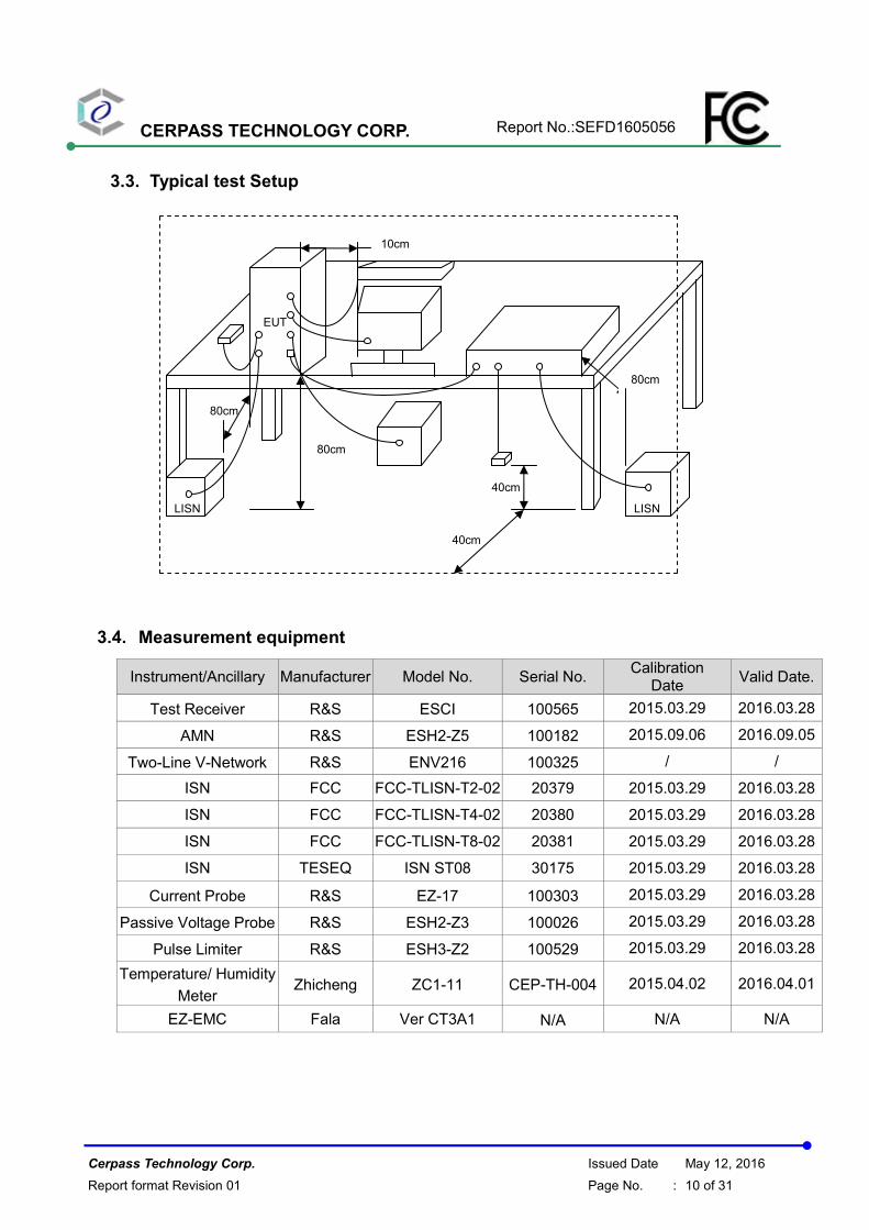
3.3. Typical test Setup
3.4. Measurement equipment
Instrument/Ancillary Manufacturer Model No. Serial No. Calibration
Date Valid Date.
Test Receiver R&S ESCI 100565 2015.03.29 2016.03.28
AMN R&S ESH2-Z5 100182 2015.09.06 2016.09.05
Two-Line V-Network R&S ENV216 100325 / /
ISN FCC FCC-TLISN-T2-02 20379 2015.03.29 2016.03.28
ISN FCC FCC-TLISN-T4-02 20380 2015.03.29 2016.03.28
ISN FCC FCC-TLISN-T8-02 20381 2015.03.29 2016.03.28
ISN TESEQ ISN ST08 30175 2015.03.29 2016.03.28
Current Probe R&S EZ-17 100303 2015.03.29 2016.03.28
Passive Voltage Probe R&S ESH2-Z3 100026 2015.03.29 2016.03.28
Pulse Limiter R&S ESH3-Z2 100529 2015.03.29 2016.03.28
Temperature/ Humidity
Meter Zhicheng ZC1-11 CEP-TH-004 2015.04.02 2016.04.01
EZ-EMC Fala Ver CT3A1 N/A N/A N/A
10cm
80cm
EUT
80cm
40cm
LISN
80cm
40cm
LISN
CERPASS TECHNOLOGY CORP. Report No.:SEFD1605056
Cerpass Technology Corp. Issued Date May 12, 2016
Report format Revision 01 Page No. : 11 of 31
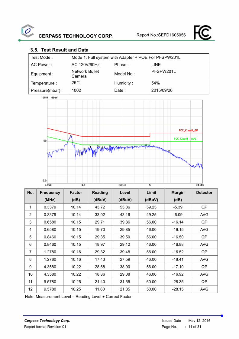
3.5. Test Result and Data
Test Mode : Mode 1: Full system with Adapter + POE For PI-SPW201L
AC Power : AC 120V/60Hz Phase : LINE
Equipment : Network Bullet Camera
Model No : PI-SPW201L
Temperature : 25℃ Humidity : 54%
Pressure(mbar) : 1002 Date : 2015/09/26
No. Frequency
(MHz)
Factor
(dB)
Reading
(dBuV)
Level
(dBuV)
Limit
(dBuV)
Margin
(dB)
Detector
1 0.3379 10.14 43.72 53.86 59.25 -5.39 QP
2 0.3379 10.14 33.02 43.16 49.25 -6.09 AVG
3 0.6580 10.15 29.71 39.86 56.00 -16.14 QP
4 0.6580 10.15 19.70 29.85 46.00 -16.15 AVG
5 0.8460 10.15 29.35 39.50 56.00 -16.50 QP
6 0.8460 10.15 18.97 29.12 46.00 -16.88 AVG
7 1.2780 10.16 29.32 39.48 56.00 -16.52 QP
8 1.2780 10.16 17.43 27.59 46.00 -18.41 AVG
9 4.3580 10.22 28.68 38.90 56.00 -17.10 QP
10 4.3580 10.22 18.86 29.08 46.00 -16.92 AVG
11 9.5780 10.25 21.40 31.65 60.00 -28.35 QP
12 9.5780 10.25 11.60 21.85 50.00 -28.15 AVG
Note: Measurement Level = Reading Level + Correct Factor
CERPASS TECHNOLOGY CORP. Report No.:SEFD1605056
Cerpass Technology Corp. Issued Date May 12, 2016
Report format Revision 01 Page No. : 12 of 31
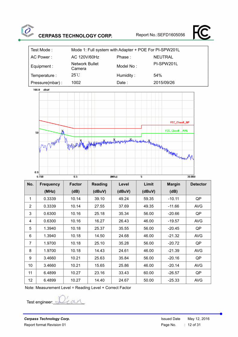
Test Mode : Mode 1: Full system with Adapter + POE For PI-SPW201L
AC Power : AC 120V/60Hz Phase : NEUTRAL
Equipment : Network Bullet Camera
Model No : PI-SPW201L
Temperature : 25℃ Humidity : 54%
Pressure(mbar) : 1002 Date : 2015/09/26
No. Frequency
(MHz)
Factor
(dB)
Reading
(dBuV)
Level
(dBuV)
Limit
(dBuV)
Margin
(dB)
Detector
1 0.3339 10.14 39.10 49.24 59.35 -10.11 QP
2 0.3339 10.14 27.55 37.69 49.35 -11.66 AVG
3 0.6300 10.16 25.18 35.34 56.00 -20.66 QP
4 0.6300 10.16 16.27 26.43 46.00 -19.57 AVG
5 1.3940 10.18 25.37 35.55 56.00 -20.45 QP
6 1.3940 10.18 14.50 24.68 46.00 -21.32 AVG
7 1.9700 10.18 25.10 35.28 56.00 -20.72 QP
8 1.9700 10.18 14.43 24.61 46.00 -21.39 AVG
9 3.4660 10.21 25.63 35.84 56.00 -20.16 QP
10 3.4660 10.21 15.65 25.86 46.00 -20.14 AVG
11 6.4899 10.27 23.16 33.43 60.00 -26.57 QP
12 6.4899 10.27 14.40 24.67 50.00 -25.33 AVG
Note: Measurement Level = Reading Level + Correct Factor
Test engineer:
CERPASS TECHNOLOGY CORP. Report No.:SEFD1605056
Cerpass Technology Corp. Issued Date May 12, 2016
Report format Revision 01 Page No. : 13 of 31
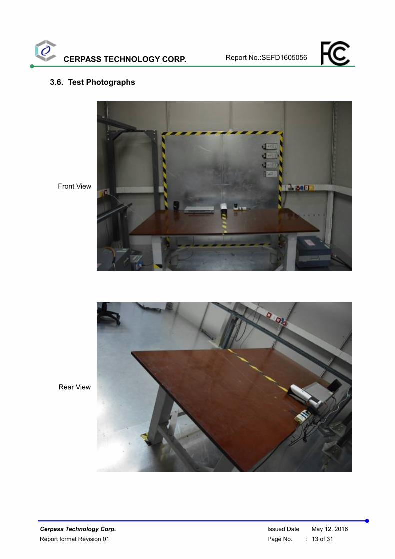
3.6. Test Photographs
Front View
Rear View
CERPASS TECHNOLOGY CORP. Report No.:SEFD1605056
Cerpass Technology Corp. Issued Date May 12, 2016
Report format Revision 01 Page No. : 14 of 31
4. Test of Radiated Emission
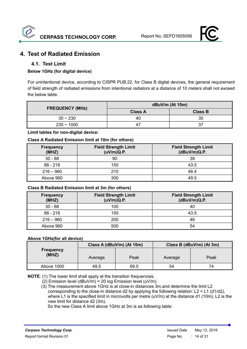
4.1. Test Limit
Below 1GHz (for digital device)
For unintentional device, according to CISPR PUB.22, for Class B digital devices, the general requirement
of field strength of radiated emissions from intentional radiators at a distance of 10 meters shall not exceed
the below table.
FREQUENCY (MHz) dBuV/m (At 10m)
Class A Class B
30 ~ 230 40 30
230 ~ 1000 47 37
Limit tables for non-digital device:
Class A Radiated Emission limit at 10m (for others)
Frequency (MHZ)
Field Strength Limit (uV/m)Q.P.
Field Strength Limit (dBuV/m)Q.P.
30 - 88 90 39
88 - 216 150 43.5
216 – 960 210 46.4
Above 960 300 49.5
Class B Radiated Emission limit at 3m (for others)
Frequency (MHZ)
Field Strength Limit (uV/m)Q.P.
Field Strength Limit (dBuV/m)Q.P.
30 - 88 100 40
88 - 216 150 43.5
216 – 960 200 46
Above 960 500 54
Above 1GHz(for all device)
Frequency (MHZ)
Class A (dBuV/m) (At 10m) Class B (dBuV/m) (At 3m)
Average Peak Average Peak
Above 1000 49.5 69.5 54 74
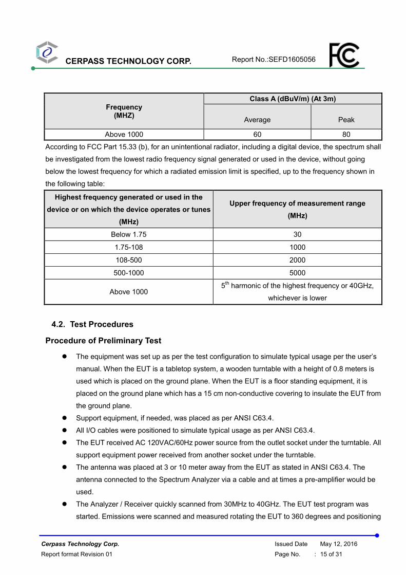
NOTE: (1) The lower limit shall apply at the transition frequencies. (2) Emission level (dBuV/m) = 20 log Emission level (uV/m). (3) The measurement above 1GHz is at close-in distances 3m,and determine the limit L2
corresponding to the close-in distance d2 by applying the following relation: L2 = L1 (d1/d2), where L1 is the specified limit in microvolts per metre (uV/m) at the distance d1 (10m), L2 is the new limit for distance d2 (3m). So the new Class A limit above 1GHz at 3m is as following table:
CERPASS TECHNOLOGY CORP. Report No.:SEFD1605056
Cerpass Technology Corp. Issued Date May 12, 2016
Report format Revision 01 Page No. : 15 of 31
Frequency (MHZ)
Class A (dBuV/m) (At 3m)
Average Peak
Above 1000 60 80
According to FCC Part 15.33 (b), for an unintentional radiator, including a digital device, the spectrum shall
be investigated from the lowest radio frequency signal generated or used in the device, without going
below the lowest frequency for which a radiated emission limit is specified, up to the frequency shown in
the following table:
Highest frequency generated or used in the
device or on which the device operates or tunes
(MHz)
Upper frequency of measurement range
(MHz)
Below 1.75 30
1.75-108 1000
108-500 2000
500-1000 5000
Above 1000 5
th harmonic of the highest frequency or 40GHz,
whichever is lower
4.2. Test Procedures
Procedure of Preliminary Test
� The equipment was set up as per the test configuration to simulate typical usage per the user’s
manual. When the EUT is a tabletop system, a wooden turntable with a height of 0.8 meters is
used which is placed on the ground plane. When the EUT is a floor standing equipment, it is
placed on the ground plane which has a 15 cm non-conductive covering to insulate the EUT from
the ground plane.
� Support equipment, if needed, was placed as per ANSI C63.4.
� All I/O cables were positioned to simulate typical usage as per ANSI C63.4.
� The EUT received AC 120VAC/60Hz power source from the outlet socket under the turntable. All
support equipment power received from another socket under the turntable.
� The antenna was placed at 3 or 10 meter away from the EUT as stated in ANSI C63.4. The
antenna connected to the Spectrum Analyzer via a cable and at times a pre-amplifier would be
used.
� The Analyzer / Receiver quickly scanned from 30MHz to 40GHz. The EUT test program was
started. Emissions were scanned and measured rotating the EUT to 360 degrees and positioning
CERPASS TECHNOLOGY CORP. Report No.:SEFD1605056
Cerpass Technology Corp. Issued Date May 12, 2016
Report format Revision 01 Page No. : 16 of 31
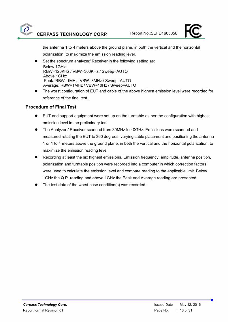
the antenna 1 to 4 meters above the ground plane, in both the vertical and the horizontal
polarization, to maximize the emission reading level.
� Set the spectrum analyzer/ Receiver in the following setting as:
Below 1GHz: RBW=120KHz / VBW=300KHz / Sweep=AUTO Above 1GHz:
Peak: RBW=1MHz, VBW=3MHz / Sweep=AUTO Average: RBW=1MHz / VBW=10Hz / Sweep=AUTO
� The worst configuration of EUT and cable of the above highest emission level were recorded for
reference of the final test.
Procedure of Final Test
� EUT and support equipment were set up on the turntable as per the configuration with highest
emission level in the preliminary test.
� The Analyzer / Receiver scanned from 30MHz to 40GHz. Emissions were scanned and
measured rotating the EUT to 360 degrees, varying cable placement and positioning the antenna
1 or 1 to 4 meters above the ground plane, in both the vertical and the horizontal polarization, to
maximize the emission reading level.
� Recording at least the six highest emissions. Emission frequency, amplitude, antenna position,
polarization and turntable position were recorded into a computer in which correction factors
were used to calculate the emission level and compare reading to the applicable limit. Below
1GHz the Q.P. reading and above 1GHz the Peak and Average reading are presented.
� The test data of the worst-case condition(s) was recorded.
CERPASS TECHNOLOGY CORP. Report No.:SEFD1605056
Cerpass Technology Corp. Issued Date May 12, 2016
Report format Revision 01 Page No. : 17 of 31
4.3. Typical test Setup
Below 1GHz Test Setup
Above 1GHz Test Setup
Turn Table 0.8M
Equipment under Test
Ground Plane
Receiver
* 10m
Antenna
CERPASS TECHNOLOGY CORP. Report No.:SEFD1605056
Cerpass Technology Corp. Issued Date May 12, 2016
Report format Revision 01 Page No. : 18 of 31
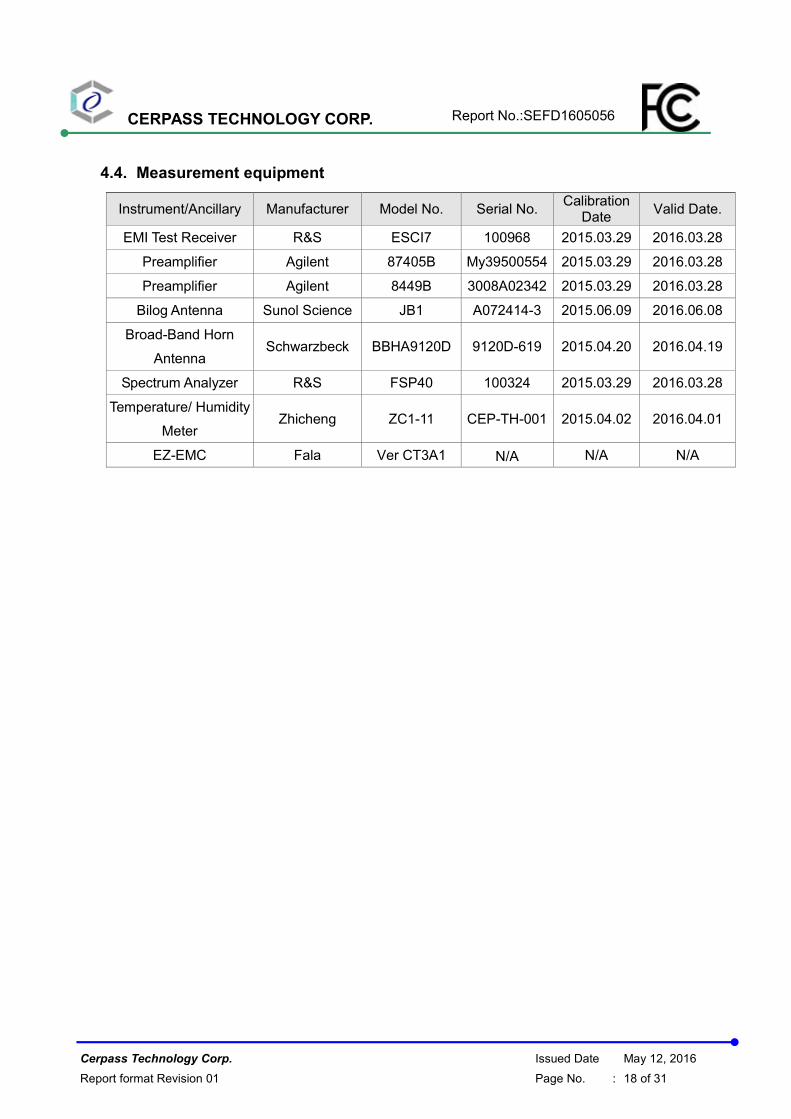
4.4. Measurement equipment
Instrument/Ancillary Manufacturer Model No. Serial No. Calibration
Date Valid Date.
EMI Test Receiver R&S ESCI7 100968 2015.03.29 2016.03.28
Preamplifier Agilent 87405B My39500554 2015.03.29 2016.03.28
Preamplifier Agilent 8449B 3008A02342 2015.03.29 2016.03.28
Bilog Antenna Sunol Science JB1 A072414-3 2015.06.09 2016.06.08
Broad-Band Horn
Antenna Schwarzbeck BBHA9120D 9120D-619 2015.04.20 2016.04.19
Spectrum Analyzer R&S FSP40 100324 2015.03.29 2016.03.28
Temperature/ Humidity
Meter Zhicheng ZC1-11 CEP-TH-001 2015.04.02 2016.04.01
EZ-EMC Fala Ver CT3A1 N/A N/A N/A
CERPASS TECHNOLOGY CORP. Report No.:SEFD1605056
Cerpass Technology Corp. Issued Date May 12, 2016
Report format Revision 01 Page No. : 19 of 31
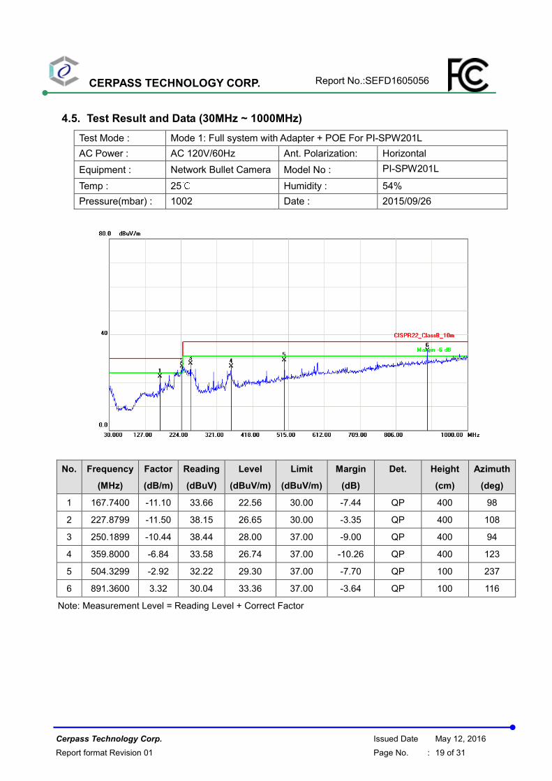
4.5. Test Result and Data (30MHz ~ 1000MHz)
Test Mode : Mode 1: Full system with Adapter + POE For PI-SPW201L
AC Power : AC 120V/60Hz Ant. Polarization: Horizontal
Equipment : Network Bullet Camera Model No : PI-SPW201L
Temp : 25℃ Humidity : 54%
Pressure(mbar) : 1002 Date : 2015/09/26
No. Frequency
(MHz)
Factor
(dB/m)
Reading
(dBuV)
Level
(dBuV/m)
Limit
(dBuV/m)
Margin
(dB)
Det. Height
(cm)
Azimuth
(deg)
1 167.7400 -11.10 33.66 22.56 30.00 -7.44 QP 400 98
2 227.8799 -11.50 38.15 26.65 30.00 -3.35 QP 400 108
3 250.1899 -10.44 38.44 28.00 37.00 -9.00 QP 400 94
4 359.8000 -6.84 33.58 26.74 37.00 -10.26 QP 400 123
5 504.3299 -2.92 32.22 29.30 37.00 -7.70 QP 100 237
6 891.3600 3.32 30.04 33.36 37.00 -3.64 QP 100 116
Note: Measurement Level = Reading Level + Correct Factor
CERPASS TECHNOLOGY CORP. Report No.:SEFD1605056
Cerpass Technology Corp. Issued Date May 12, 2016
Report format Revision 01 Page No. : 20 of 31
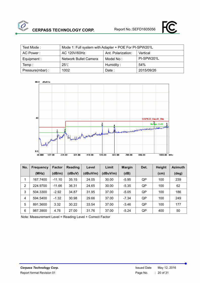
Test Mode : Mode 1: Full system with Adapter + POE For PI-SPW201L
AC Power : AC 120V/60Hz Ant. Polarization: Vertical
Equipment : Network Bullet Camera Model No : PI-SPW201L
Temp : 25℃ Humidity : 54%
Pressure(mbar) : 1002 Date : 2015/09/26
No. Frequency
(MHz)
Factor
(dB/m)
Reading
(dBuV)
Level
(dBuV/m)
Limit
(dBuV/m)
Margin
(dB)
Det. Height
(cm)
Azimuth
(deg)
1 167.7400 -11.10 35.15 24.05 30.00 -5.95 QP 100 239
2 224.9700 -11.66 36.31 24.65 30.00 -5.35 QP 100 62
3 504.3300 -2.92 34.87 31.95 37.00 -5.05 QP 100 186
4 594.5400 -1.32 30.98 29.66 37.00 -7.34 QP 100 249
5 891.3600 3.32 30.22 33.54 37.00 -3.46 QP 100 177
6 987.3900 4.76 27.00 31.76 37.00 -5.24 QP 400 50
Note: Measurement Level = Reading Level + Correct Factor
CERPASS TECHNOLOGY CORP. Report No.:SEFD1605056
Cerpass Technology Corp. Issued Date May 12, 2016
Report format Revision 01 Page No. : 21 of 31
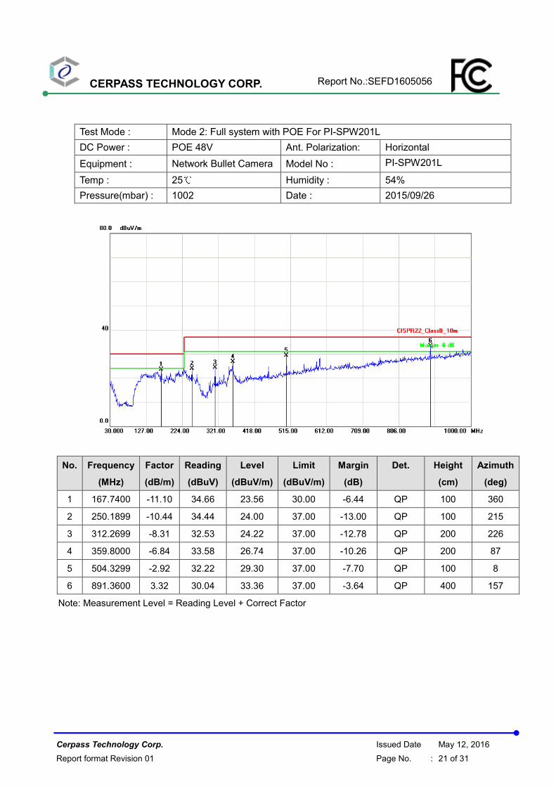
Test Mode : Mode 2: Full system with POE For PI-SPW201L
DC Power : POE 48V Ant. Polarization: Horizontal
Equipment : Network Bullet Camera Model No : PI-SPW201L
Temp : 25℃ Humidity : 54%
Pressure(mbar) : 1002 Date : 2015/09/26
No. Frequency
(MHz)
Factor
(dB/m)
Reading
(dBuV)
Level
(dBuV/m)
Limit
(dBuV/m)
Margin
(dB)
Det. Height
(cm)
Azimuth
(deg)
1 167.7400 -11.10 34.66 23.56 30.00 -6.44 QP 100 360
2 250.1899 -10.44 34.44 24.00 37.00 -13.00 QP 100 215
3 312.2699 -8.31 32.53 24.22 37.00 -12.78 QP 200 226
4 359.8000 -6.84 33.58 26.74 37.00 -10.26 QP 200 87
5 504.3299 -2.92 32.22 29.30 37.00 -7.70 QP 100 8
6 891.3600 3.32 30.04 33.36 37.00 -3.64 QP 400 157
Note: Measurement Level = Reading Level + Correct Factor
CERPASS TECHNOLOGY CORP. Report No.:SEFD1605056
Cerpass Technology Corp. Issued Date May 12, 2016
Report format Revision 01 Page No. : 22 of 31
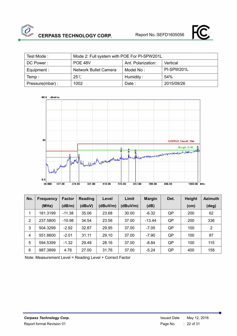
Test Mode : Mode 2: Full system with POE For PI-SPW201L
DC Power : POE 48V Ant. Polarization: Vertical
Equipment : Network Bullet Camera Model No : PI-SPW201L
Temp : 25℃ Humidity : 54%
Pressure(mbar) : 1002 Date : 2015/09/26
No. Frequency
(MHz)
Factor
(dB/m)
Reading
(dBuV)
Level
(dBuV/m)
Limit
(dBuV/m)
Margin
(dB)
Det. Height
(cm)
Azimuth
(deg)
1 181.3199 -11.38 35.06 23.68 30.00 -6.32 QP 200 62
2 237.5800 -10.98 34.54 23.56 37.00 -13.44 QP 200 336
3 504.3299 -2.92 32.87 29.95 37.00 -7.05 QP 100 2
4 551.8600 -2.01 31.11 29.10 37.00 -7.90 QP 100 87
5 594.5399 -1.32 29.48 28.16 37.00 -8.84 QP 100 115
6 987.3899 4.76 27.00 31.76 37.00 -5.24 QP 400 158
Note: Measurement Level = Reading Level + Correct Factor
CERPASS TECHNOLOGY CORP. Report No.:SEFD1605056
Cerpass Technology Corp. Issued Date May 12, 2016
Report format Revision 01 Page No. : 23 of 31
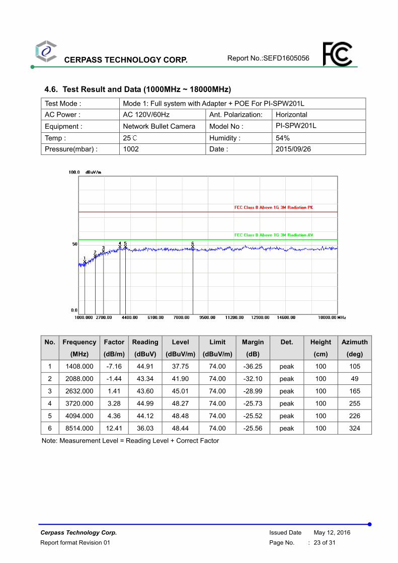
4.6. Test Result and Data (1000MHz ~ 18000MHz)
Test Mode : Mode 1: Full system with Adapter + POE For PI-SPW201L
AC Power : AC 120V/60Hz Ant. Polarization: Horizontal
Equipment : Network Bullet Camera Model No : PI-SPW201L
Temp : 25℃ Humidity : 54%
Pressure(mbar) : 1002 Date : 2015/09/26
No. Frequency
(MHz)
Factor
(dB/m)
Reading
(dBuV)
Level
(dBuV/m)
Limit
(dBuV/m)
Margin
(dB)
Det. Height
(cm)
Azimuth
(deg)
1 1408.000 -7.16 44.91 37.75 74.00 -36.25 peak 100 105
2 2088.000 -1.44 43.34 41.90 74.00 -32.10 peak 100 49
3 2632.000 1.41 43.60 45.01 74.00 -28.99 peak 100 165
4 3720.000 3.28 44.99 48.27 74.00 -25.73 peak 100 255
5 4094.000 4.36 44.12 48.48 74.00 -25.52 peak 100 226
6 8514.000 12.41 36.03 48.44 74.00 -25.56 peak 100 324
Note: Measurement Level = Reading Level + Correct Factor
CERPASS TECHNOLOGY CORP. Report No.:SEFD1605056
Cerpass Technology Corp. Issued Date May 12, 2016
Report format Revision 01 Page No. : 24 of 31
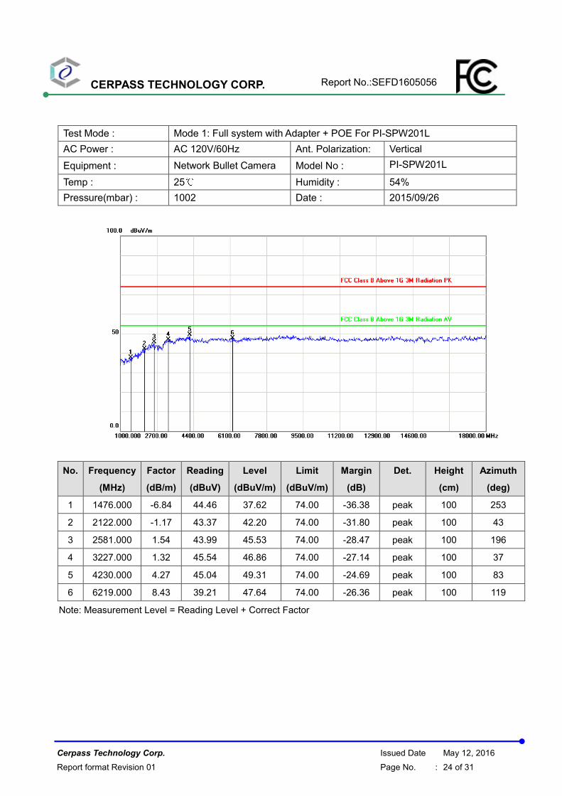
Test Mode : Mode 1: Full system with Adapter + POE For PI-SPW201L
AC Power : AC 120V/60Hz Ant. Polarization: Vertical
Equipment : Network Bullet Camera Model No : PI-SPW201L
Temp : 25℃ Humidity : 54%
Pressure(mbar) : 1002 Date : 2015/09/26
No. Frequency
(MHz)
Factor
(dB/m)
Reading
(dBuV)
Level
(dBuV/m)
Limit
(dBuV/m)
Margin
(dB)
Det. Height
(cm)
Azimuth
(deg)
1 1476.000 -6.84 44.46 37.62 74.00 -36.38 peak 100 253
2 2122.000 -1.17 43.37 42.20 74.00 -31.80 peak 100 43
3 2581.000 1.54 43.99 45.53 74.00 -28.47 peak 100 196
4 3227.000 1.32 45.54 46.86 74.00 -27.14 peak 100 37
5 4230.000 4.27 45.04 49.31 74.00 -24.69 peak 100 83
6 6219.000 8.43 39.21 47.64 74.00 -26.36 peak 100 119
Note: Measurement Level = Reading Level + Correct Factor
CERPASS TECHNOLOGY CORP. Report No.:SEFD1605056
Cerpass Technology Corp. Issued Date May 12, 2016
Report format Revision 01 Page No. : 25 of 31
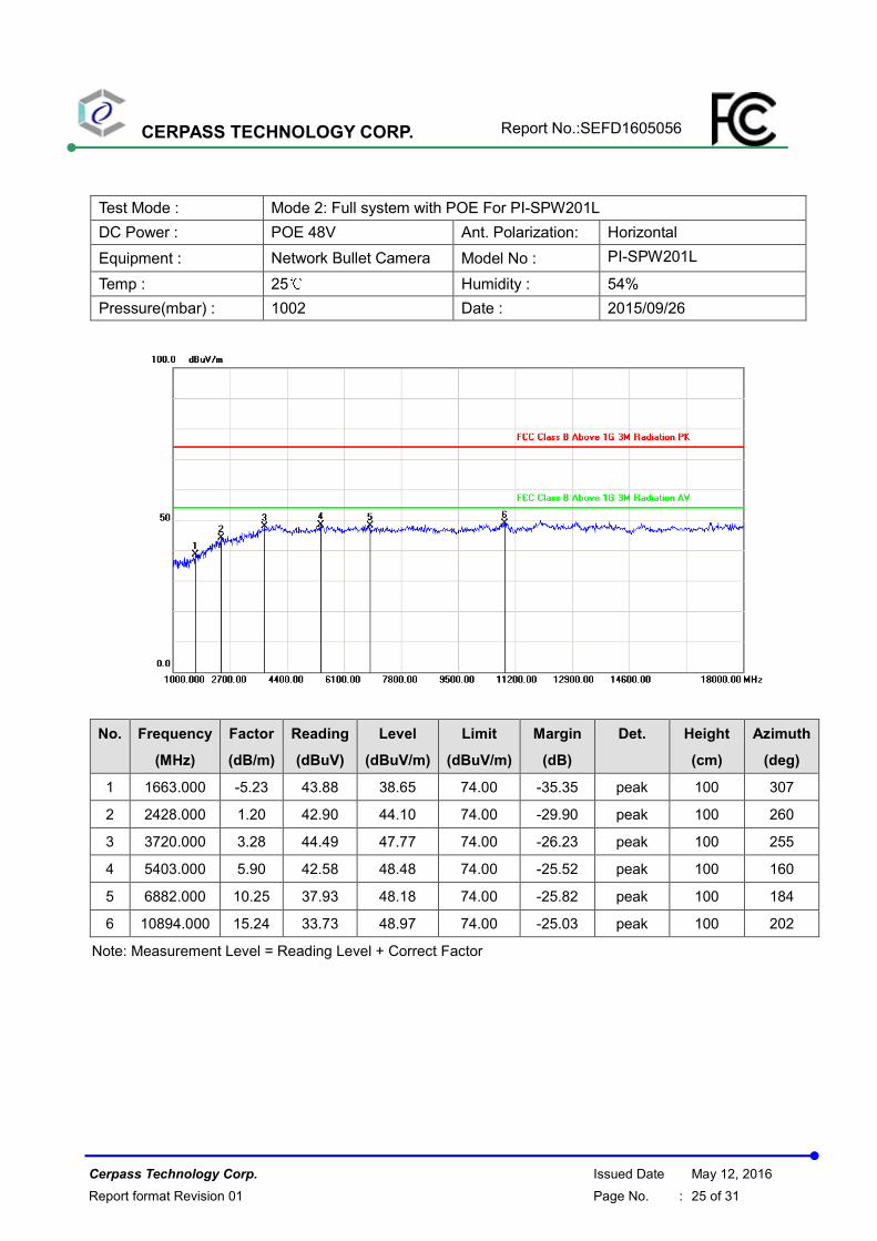
Test Mode : Mode 2: Full system with POE For PI-SPW201L
DC Power : POE 48V Ant. Polarization: Horizontal
Equipment : Network Bullet Camera Model No : PI-SPW201L
Temp : 25℃ Humidity : 54%
Pressure(mbar) : 1002 Date : 2015/09/26
No. Frequency
(MHz)
Factor
(dB/m)
Reading
(dBuV)
Level
(dBuV/m)
Limit
(dBuV/m)
Margin
(dB)
Det. Height
(cm)
Azimuth
(deg)
1 1663.000 -5.23 43.88 38.65 74.00 -35.35 peak 100 307
2 2428.000 1.20 42.90 44.10 74.00 -29.90 peak 100 260
3 3720.000 3.28 44.49 47.77 74.00 -26.23 peak 100 255
4 5403.000 5.90 42.58 48.48 74.00 -25.52 peak 100 160
5 6882.000 10.25 37.93 48.18 74.00 -25.82 peak 100 184
6 10894.000 15.24 33.73 48.97 74.00 -25.03 peak 100 202
Note: Measurement Level = Reading Level + Correct Factor
CERPASS TECHNOLOGY CORP. Report No.:SEFD1605056
Cerpass Technology Corp. Issued Date May 12, 2016
Report format Revision 01 Page No. : 26 of 31
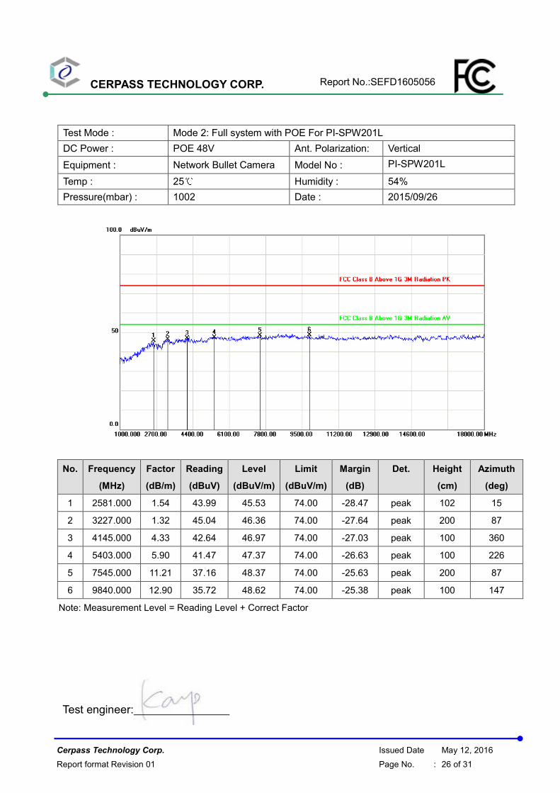
Test Mode : Mode 2: Full system with POE For PI-SPW201L
DC Power : POE 48V Ant. Polarization: Vertical
Equipment : Network Bullet Camera Model No : PI-SPW201L
Temp : 25℃ Humidity : 54%
Pressure(mbar) : 1002 Date : 2015/09/26
No. Frequency
(MHz)
Factor
(dB/m)
Reading
(dBuV)
Level
(dBuV/m)
Limit
(dBuV/m)
Margin
(dB)
Det. Height
(cm)
Azimuth
(deg)
1 2581.000 1.54 43.99 45.53 74.00 -28.47 peak 102 15
2 3227.000 1.32 45.04 46.36 74.00 -27.64 peak 200 87
3 4145.000 4.33 42.64 46.97 74.00 -27.03 peak 100 360
4 5403.000 5.90 41.47 47.37 74.00 -26.63 peak 100 226
5 7545.000 11.21 37.16 48.37 74.00 -25.63 peak 200 87
6 9840.000 12.90 35.72 48.62 74.00 -25.38 peak 100 147
Note: Measurement Level = Reading Level + Correct Factor
Test engineer:
CERPASS TECHNOLOGY CORP. Report No.:SEFD1605056
Cerpass Technology Corp. Issued Date May 12, 2016
Report format Revision 01 Page No. : 27 of 31
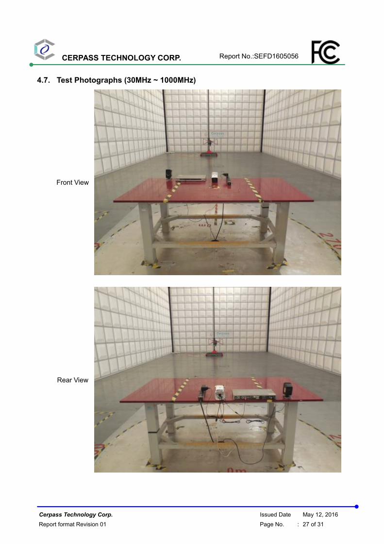
4.7. Test Photographs (30MHz ~ 1000MHz)
Front View
Rear View
CERPASS TECHNOLOGY CORP. Report No.:SEFD1605056
Cerpass Technology Corp. Issued Date May 12, 2016
Report format Revision 01 Page No. : 28 of 31
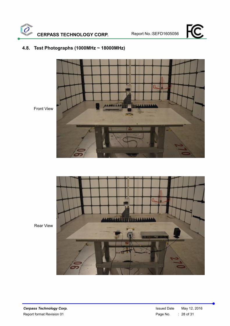
4.8. Test Photographs (1000MHz ~ 18000MHz)
Front View
Rear View
CERPASS TECHNOLOGY CORP. Report No.:SEFD1605056
Cerpass Technology Corp. Issued Date May 12, 2016
Report format Revision 01 Page No. : 29 of 31
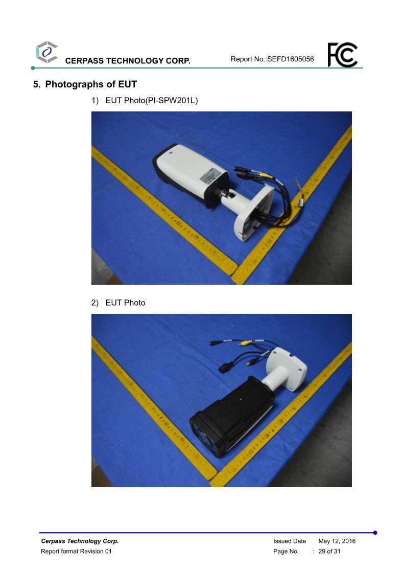
5. Photographs of EUT
1) EUT Photo(PI-SPW201L)
2) EUT Photo
CERPASS TECHNOLOGY CORP. Report No.:SEFD1605056
Cerpass Technology Corp. Issued Date May 12, 2016
Report format Revision 01 Page No. : 30 of 31
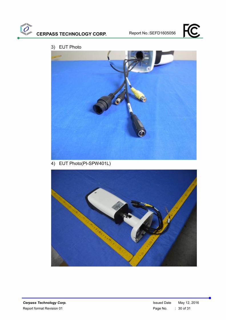
3) EUT Photo
4) EUT Photo(PI-SPW401L)
CERPASS TECHNOLOGY CORP. Report No.:SEFD1605056
Cerpass Technology Corp. Issued Date May 12, 2016
Report format Revision 01 Page No. : 31 of 31
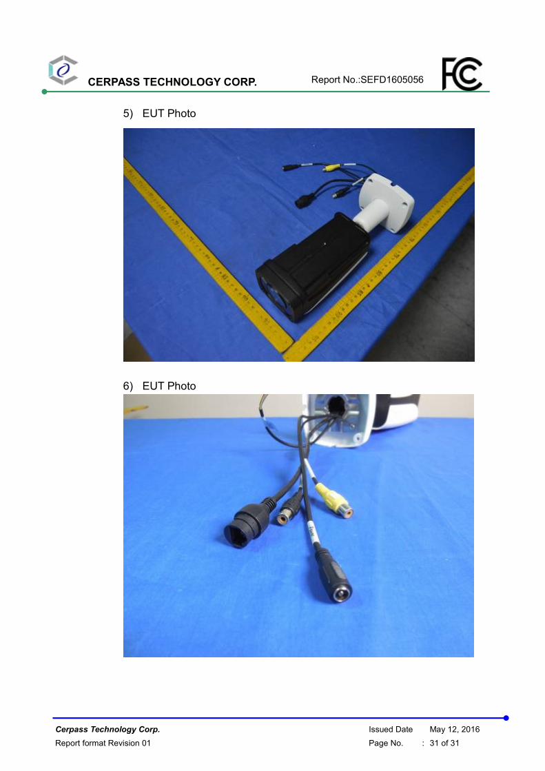
5) EUT Photo
6) EUT Photo