fcs effectors workbook 21002 - nasa€¦ · answers to the questions in the workbook in appx b....
TRANSCRIPT

USA007263 Rev. B
Space Flight Operations Contract
FCS/Effectors Workbook
FCS/EFF 21002
March 7, 2006
This document has been reviewed and updated. No subsequent updates to this document are anticipated
or required due to the approaching shuttle program closure.
Contract NAS9-20000
Copyright 2004 by United Space Alliance, LLC. These materials are sponsored by the National Aeronautics and Space Administration under Contract NAS9-20000. The U.S. Government retains a paid-up, nonexclusive, irrevocable
worldwide license in such materials to reproduce, prepare derivative works, distribute copies to the public, and to perform publicly and display publicly, by or on behalf of the U.S. Government. All other rights are reserved by the copyright owner.
USA007263 Rev. B
Contract NAS9-20000
FCS/Effectors Workbook FCS/EFF 21002
Prepared by
Original approval obtained Wes Penny, Book Manager USA/G&C/Propulsion
Approved by
Original approval obtained Miguel Sequeira, Manager USA/G&C/Propulsion

USA007263 Rev. B
REVISION LOG
Rev. letter
Change no.
Description Date
Basic Supersedes TD341 05/19/2003 Rev. A Updated the Preface. Removed the eval form
from Appx B, and made it the last page independent of the document. Put the answers to the questions in the workbook in Appx B. Fixed typo in Figure 1.1. Added copyright statement to the cover page.
08/26/2004
Rev. B Changed manager name, corrected wrong display in Fig. 7-10, added reference to the MPS TVC workbook in Section 3, added statement on front cover.
03/07/2006
USA007263 Rev. B
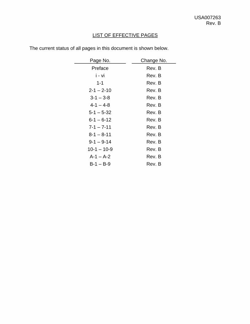
LIST OF EFFECTIVE PAGES
The current status of all pages in this document is shown below.
Page No. Change No.
Preface Rev. B
i - vi Rev. B
1-1 Rev. B
2-1 – 2-10 Rev. B
3-1 – 3-8 Rev. B
4-1 – 4-8 Rev. B
5-1 – 5-32 Rev. B
6-1 – 6-12 Rev. B
7-1 – 7-11 Rev. B
8-1 – 8-11 Rev. B
9-1 – 9-14 Rev. B
10-1 – 10-9 Rev. B
A-1 – A-2 Rev. B
B-1 – B-9 Rev. B
USA007263 Rev. B
PREFACE
The content of this document was provided by the United Space Alliance (USA) Guidance and Control/Propulsion Department, Space Flight Training and Facility Operations Division, Mission Operations Directorate (MOD), Lyndon B. Johnson Space Center (JSC), National Aeronautics and Space Administration (NASA). Technical documentation support was provided by Integrated Documentation Services (IDS). Any questions concerning this workbook or any recommendations should be directed to the book manager.
This training manual is for training purposes only and should not be used as a source of operational data. All numerical data, display, and checklist references are intended as examples. To determine any prerequisites before using this document, consult your applicable Certification Plan. For shuttle manuals, consult the appropriate flight controller’s certification guide (Blue Book) or the Crew Training Catalog. For International Space Station manuals, consult the appropriate Space Station Certification Guide or Training Administration Management System (TAMS). The applicable training package should be studied before attending any classroom session or lesson for which this is a prerequisite.
If this workbook is being read as part of a formal syllabus, the reader should complete the training materials evaluation form at the end of the document. The eval form does not need to be signed.
USA007263 Rev. B
i
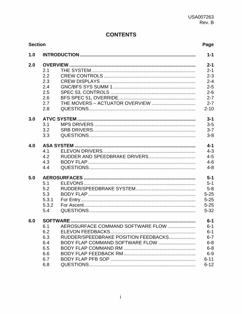
CONTENTS
Section Page
1.0 INTRODUCTION ....................................................................................... 1-1
2.0 OVERVIEW ............................................................................................... 2-1 2.1 THE SYSTEM .............................................................................. 2-1 2.2 CREW CONTROLS ..................................................................... 2-3 2.3 CREW DISPLAYS ....................................................................... 2-4 2.4 GNC/BFS SYS SUMM 1 .............................................................. 2-5 2.5 SPEC 53, CONTROLS ................................................................ 2-6 2.6 BFS SPEC 51, OVERRIDE .......................................................... 2-7 2.7 THE MOVERS – ACTUATOR OVERVIEW ................................. 2-7 2.8 QUESTIONS ................................................................................ 2-10
3.0 ATVC SYSTEM ......................................................................................... 3-1 3.1 MPS DRIVERS ............................................................................ 3-5 3.2 SRB DRIVERS ............................................................................. 3-7 3.3 QUESTIONS ................................................................................ 3-8
4.0 ASA SYSTEM ........................................................................................... 4-1 4.1 ELEVON DRIVERS...................................................................... 4-3 4.2 RUDDER AND SPEEDBRAKE DRIVERS ................................... 4-5 4.3 BODY FLAP ................................................................................. 4-6 4.4 QUESTIONS ................................................................................ 4-8
5.0 AEROSURFACES .................................................................................... 5-1 5.1 ELEVONS .................................................................................... 5-1 5.2 RUDDER/SPEEDBRAKE SYSTEM ............................................. 5-8 5.3 BODY FLAP ................................................................................. 5-25 5.3.1 For Entry ...................................................................................... 5-25 5.3.2 For Ascent .................................................................................... 5-25 5.4 QUESTIONS ................................................................................ 5-32
6.0 SOFTWARE .............................................................................................. 6-1 6.1 AEROSURFACE COMMAND SOFTWARE FLOW ..................... 6-1 6.2 ELEVON FEEDBACKS ................................................................ 6-1 6.3 RUDDER/SPEEDBRAKE POSITION FEEDBACKS .................... 6-7 6.4 BODY FLAP COMMAND SOFTWARE FLOW ............................ 6-8 6.5 BODY FLAP COMMAND RM ...................................................... 6-8 6.6 BODY FLAP FEEDBACK RM ...................................................... 6-9 6.7 BODY FLAP PFB SOP ................................................................ 6-11 6.8 QUESTIONS ................................................................................ 6-12

USA007263 Rev. B
ii
Section Page
7.0 CREW DISPLAYS ..................................................................................... 7-1 7.1 SURFACE POSITION INDICATOR ............................................. 7-1 7.2 RCS ACTIVITY LIGHTS .............................................................. 7-5 7.3 CRT DISPLAYS ........................................................................... 7-5 7.3.1 GNC SYS SUMM 1 ...................................................................... 7-5 7.3.2 SPEC 53 ...................................................................................... 7-6 7.3.3 BFS SPEC 51 .............................................................................. 7-7 7.3.4 FCS/Dedicated Display Checkout ................................................ 7-8 7.4 QUESTIONS ................................................................................ 7-10
8.0 FCS MALFUNCTIONS .............................................................................. 8-1 8.1 INTRODUCTION ......................................................................... 8-1 8.2 COMMAND ERROR .................................................................... 8-1 8.2.1 Failure Description ....................................................................... 8-1 8.2.2 Result of Failure ........................................................................... 8-1 8.2.3 Caution and Warning Response .................................................. 8-1 8.3 POSITION FEEDBACK ERROR (ASA ONLY) ............................ 8-4 8.3.1 Failure Description ....................................................................... 8-4 8.3.2 Result of Failure ........................................................................... 8-4 8.3.3 Caution and Warning Response .................................................. 8-4 8.4 MDM/GPC FAILURES ................................................................. 8-5 8.4.1 Failure Description ....................................................................... 8-5 8.5 ASA/ATVC INTERNAL POWER FAILURE .................................. 8-8 8.5.1 Failure Description ....................................................................... 8-8 8.5.2 Result of Failure ........................................................................... 8-8 8.5.3 Caution and Warning Response .................................................. 8-8 8.6 ISOLATION VALVE POWER FAILURE ....................................... 8-10 8.6.1 Failure Description ....................................................................... 8-10 8.6.2 Result of Failure ........................................................................... 8-10 8.6.3 Caution and Warning Response .................................................. 8-10 8.7 QUESTIONS ................................................................................ 8-11
9.0 FCS CHANNEL MANAGEMENT .............................................................. 9-1 9.1 INTRODUCTION ......................................................................... 9-1 9.2 FCS CH 1 (2,3,4) (2ND FAIL) ...................................................... 9-1 9.2.1 First FCS Channel Failure ............................................................ 9-1 9.2.2 Second FCS Channel Failure ...................................................... 9-1 9.2.3 Two Seconds Between Switch Throws ........................................ 9-3 9.3 GPC/FA MDM FAILURES ............................................................ 9-3 9.3.1 Affected FCS Channel Off ............................................................ 9-3 9.3.2 FCS Channels to Override ........................................................... 9-5 9.3.3 Deselect Affected Feedback ........................................................ 9-5 9.4 EXAMPLES OF THE FCS CH 1 (2,3,4) (2ND FAIL) AND
GPC/FA MDM I/O ERROR PROCEDURES ................................ 9-5

USA007263 Rev. B
iii
Section Page
9.5 PRIORITIZING FCS CHANNEL ACTIONS .................................. 9-6 9.5.1 Main Engine Failures ................................................................... 9-9 9.6 RESTRINGING ............................................................................ 9-9 9.7 MCC CALLS ................................................................................ 9-10 9.8 BODY FLAP ................................................................................. 9-11 9.8.1 Body Flap Fail .............................................................................. 9-11 9.8.2 Body Flap Hold ............................................................................ 9-12 9.8.3 Body Flap Cycle ........................................................................... 9-13 9.8.4 BDY FLP SW ............................................................................... 9-13 9.9 SUMMARY ................................................................................... 9-13 9.10 QUESTIONS ................................................................................ 9-14
10.0 SURFACE DRIVE CHECKS AND HYDRAULIC WARMUP ..................... 10-1 10.1 ORBITER ACTUATOR SLEW CHECK –
MAJOR MODE101 – 25 HZ ......................................................... 10-1 10.2 AEROSURFACE DRIVE TEST OPS 8 ........................................ 10-1 10.3 BODY FLAP PILOT VALVE CHECK – OPS 8 ............................. 10-3 10.4 SECONDARY ACTUATOR CHECK – OPS 8 .............................. 10-4 10.4.1 Secondary Actuator Check – Channel 1 ...................................... 10-4 10.5 SURFACE TEST - OPS 8 ............................................................ 10-6 10.6 HYDRAULIC THERMAL CONDITIONING ................................... 10-7 10.7 QUESTIONS ................................................................................ 10-9
Appendix
A ACRONYMS AND ABBREVIATIONS ...................................................... A-1
B ANSWERS ................................................................................................ B-1

USA007263 Rev. B
iv
FIGURES
Figure Page 1-1 Orbiter aerosurfaces .................................................................................. 1-1 2-1 FCS effectors ............................................................................................. 2-2 2-2 SSME/SRB actuators ................................................................................ 2-2 2-3 Crew controls ............................................................................................. 2-3 2-4 FCS/ASA/ATVC switches .......................................................................... 2-4 2-5 C&W annunciator panel ............................................................................. 2-5 2-6 SPI display................................................................................................. 2-5 2-7 GNC SYS SUMM 1 display ....................................................................... 2-6 2-8 CONTROLS display .................................................................................. 2-6 2-9 OVERRIDE display .................................................................................... 2-7 2-10 Typical actuator ......................................................................................... 2-8 2-11 Main engine electrohydraulic servoactuator (exterior
physical characteristics) ............................................................................ 2-9 2-12 Elevon actuator .......................................................................................... 2-9 3-1 ATVC command flow ................................................................................. 3-1 3-2 FCS/ATVC switch power ........................................................................... 3-2 3-3 ATVC schematic ........................................................................................ 3-4 3-4 ATVC fault detection time counter ............................................................. 3-5 4-1 ASA/FCS channel configuration ................................................................ 4-2 4-2 ASA description ......................................................................................... 4-3 4-3 Fault detection time counter curve ............................................................. 4-4 4-4 Elevon driver .............................................................................................. 4-5 4-5 Rudder/speedbrake driver ......................................................................... 4-6 4-6 Body flap circuit ......................................................................................... 4-7 5-1 Elevon functions ........................................................................................ 5-1 5-2 Switching valve .......................................................................................... 5-3 5-3 Typical elevon actuator .............................................................................. 5-4 5-4 Servovalve schematic ................................................................................ 5-5 5-5 Servovalve operation ................................................................................. 5-6 5-6 Secondary force-sum actuator and primary actuator ................................. 5-7 5-7 Elevon actuator .......................................................................................... 5-8 5-8 Rudder/speedbrake function ..................................................................... 5-10 5-9 Combined rudder/speedbrake deflection ................................................... 5-11 5-10 Rudder/speedbrake actuator location ........................................................ 5-12 5-11 Rudder/speedbrake hydraulic supply overview ......................................... 5-13 5-12 Rudder/speedbrake actuation subsystem ................................................. 5-15 5-13 Triplex power valve .................................................................................... 5-16

USA007263 Rev. B
v
Figure Page 5-14 Hydraulic motor/brake assembly ............................................................... 5-17 5-15 Differential gearbox ................................................................................... 5-18 5-16 Mixer gearbox ............................................................................................ 5-19 5-17 Drive shaft connections ............................................................................. 5-20 5-18 Rudder/speedbrake geared rotary actuator ............................................... 5-21 5-19 Typical geared actuator (gear assembly) .................................................. 5-22 5-20 Rudder and speedbrake movements ......................................................... 5-24 5-21 Body flap function ...................................................................................... 5-25 5-22 Body flap actuator hydraulic supply ........................................................... 5-26 5-23 Body flap PDU ........................................................................................... 5-27 5-24 Body flap solenoids/hydraulic actuator ...................................................... 5-29 5-25 Hydraulic motor/brake assembly ............................................................... 5-30 5-26 Body flap differential gearbox and rotary actuators ................................... 5-31 6-1 Aerosurface command software data flow ................................................. 6-1 6-2 Elevon feedback software data flow .......................................................... 6-3 6-3 FDIR .......................................................................................................... 6-3 6-4 PASS selection filter .................................................................................. 6-4 6-5 Elevon saturation indications ..................................................................... 6-5 6-6 Elevon primary ΔP FDIR and SF ............................................................... 6-6 6-7 Elevon primary ΔP RM – OPS 3 and 6 ...................................................... 6-7 6-8 Rudder PFB SOP ...................................................................................... 6-7 6-9 Speedbrake PFB SOP ............................................................................... 6-8 6-10 Body flap command software data flow ..................................................... 6-8 6-11 Body flap PFB RM (no failures) ................................................................. 6-10 6-12 Body flap PFB RM after one failure ........................................................... 6-10 6-13 Body flap PFB SOP ................................................................................... 6-11 7-1 Surface position indicator .......................................................................... 7-1 7-2 Elevon position – SPI ................................................................................ 7-2 7-3 Aileron position – SPI ................................................................................ 7-3 7-4 Body flap position – SPI ............................................................................ 7-4 7-5 Rudder position – crew interface OPS 3 and 6 .......................................... 7-4 7-6 Speedbrake position – SPI OPS 3, 6 ......................................................... 7-5 7-7 RCS activity lights ...................................................................................... 7-5 7-8 GNC SYS SUMM 1 display ....................................................................... 7-6 7-9 CONTROLS display .................................................................................. 7-6 7-10 BFS 51 OVERRIDE display ....................................................................... 7-8 7-11 FCS/DED DIS C/O .................................................................................... 7-8 8-1 GNC SYS SUMM 1 display ....................................................................... 8-2 8-2 CONTROLS display .................................................................................. 8-2 8-3 GNC SYS SUMM 1 display ....................................................................... 8-3 8-4 CONTROLS display .................................................................................. 8-3
USA007263 Rev. B
vi
Figure Page 8-5 Panel F7 .................................................................................................... 8-4 8-6 GNC SYS SUMM 1 display ....................................................................... 8-5 8-7 CONTROLS display .................................................................................. 8-5 8-8 Panel F7 .................................................................................................... 8-7 8-9 GNC SYS SUMM 1 display ....................................................................... 8-7 8-10 CONTROLS display .................................................................................. 8-8 8-11 GNC SYS SUMM 1 display ....................................................................... 8-9 8-12 CONTROLS display (ASA 1 failed) ........................................................... 8-9 8-13 CONTROLS display (ATVC 1 failed) ......................................................... 8-10 9-1 FCS Ch 1 (2,3,4) (2nd fail) procedure ........................................................ 9-1 9-2 GNC SPEC 53 ........................................................................................... 9-2 9-3 GNC SPEC 53 ........................................................................................... 9-2 9-4 Switches .................................................................................................... 9-3 9-5 GPC fail ..................................................................................................... 9-4 9-6 MDM fail .................................................................................................... 9-4 9-7 Right SSME pitch Ch 2 and right SSME yaw Ch 2 bypassed .................... 9-5 9-8 FA 2 MDM failed and ROB Ch 4 bypassed ............................................... 9-6 9-9 ASA 2 failed and ROB Ch 4 bypassed ..................................................... 9-8 9-10 Center SSME pitch Ch 3 bypassed and ATVC Ch 4 failure ...................... 9-8 9-11 FCS channel configurations ...................................................................... 9-10 9-12 GPC cue card ............................................................................................ 9-10 9-13 ROB Ch 4 bypassed .................................................................................. 9-11 9-14 SYS SUMM 1 ............................................................................................ 9-12 9-15 SYS SUMM 1 ............................................................................................ 9-12 9-16 SYS SUMM 1 ............................................................................................ 9-13 10-1 Trapezoidal function .................................................................................. 10-1 10-2 FCS/DED DIS C/O .................................................................................... 10-2 10-3 FCS/DED DIS C/O display detail ............................................................... 10-3 10-4 Body flap pilot valve check ........................................................................ 10-4 10-5 FCS/DED DIS C/O .................................................................................... 10-5 10-6 SWITCH/SURF – OPS 8 ........................................................................... 10-6 10-7 Triangular function ..................................................................................... 10-7
USA007263 Rev. B
1-1
1.0 INTRODUCTION
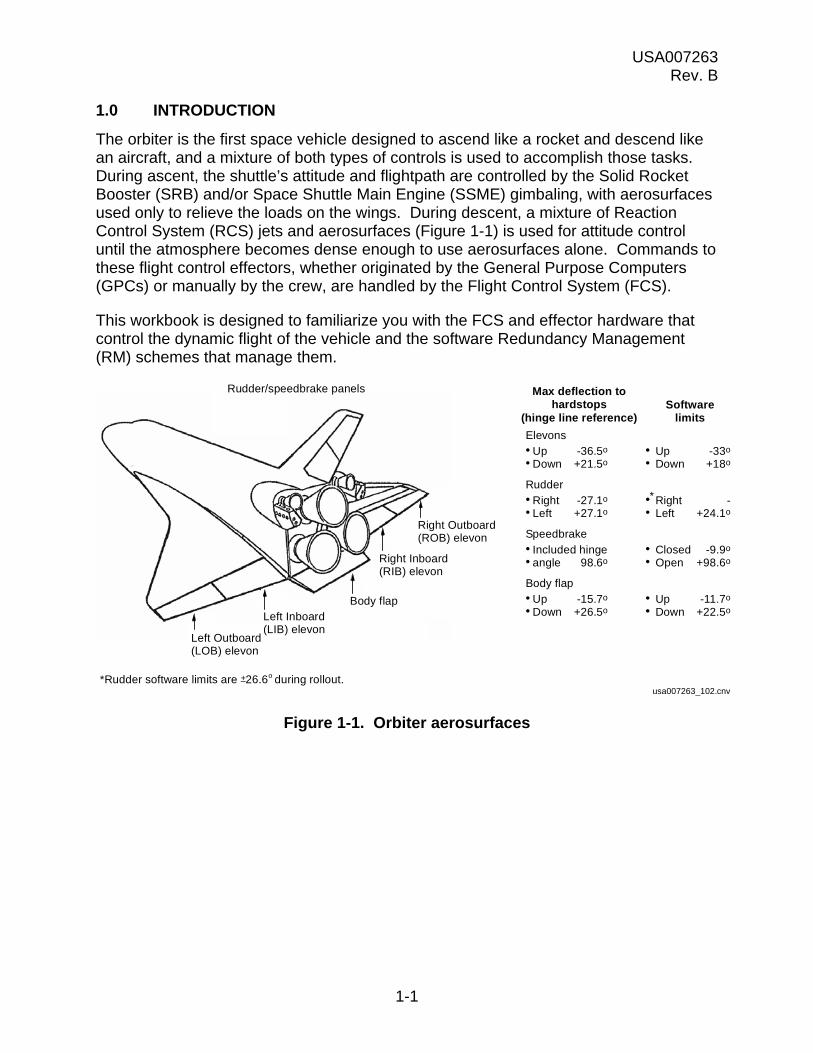
The orbiter is the first space vehicle designed to ascend like a rocket and descend like an aircraft, and a mixture of both types of controls is used to accomplish those tasks. During ascent, the shuttle’s attitude and flightpath are controlled by the Solid Rocket Booster (SRB) and/or Space Shuttle Main Engine (SSME) gimbaling, with aerosurfaces used only to relieve the loads on the wings. During descent, a mixture of Reaction Control System (RCS) jets and aerosurfaces (Figure 1-1) is used for attitude control until the atmosphere becomes dense enough to use aerosurfaces alone. Commands to these flight control effectors, whether originated by the General Purpose Computers (GPCs) or manually by the crew, are handled by the Flight Control System (FCS).
This workbook is designed to familiarize you with the FCS and effector hardware that control the dynamic flight of the vehicle and the software Redundancy Management (RM) schemes that manage them.
Figure 1-1. Orbiter aerosurfaces
Rudder/speedbrake panels
Left Inboard(LIB) elevon
Left Outboard(LOB) elevon
Body flap
Right Outboard(ROB) elevon
Right Inboard(RIB) elevon
Max deflection tohardstops
(hinge line reference)
Elevons
UpDown
-36.5o
+21.5o
Softwarelimits
UpDown
-33o
+18o
Rudder
RightLeft
-27.1o
+27.1oRightLeft
-+24.1o
Speedbrake
Included hingeangle 98.6o
ClosedOpen
-9.9o
+98.6o
Body flap
UpDown
-15.7o
+26.5oUpDown
-11.7o
+22.5o
usa007263_102.cnv*Rudder software limits are +26.6 during rollout.o
*
USA007263 Rev. B
2-1
2.0 OVERVIEW
2.1 THE SYSTEM
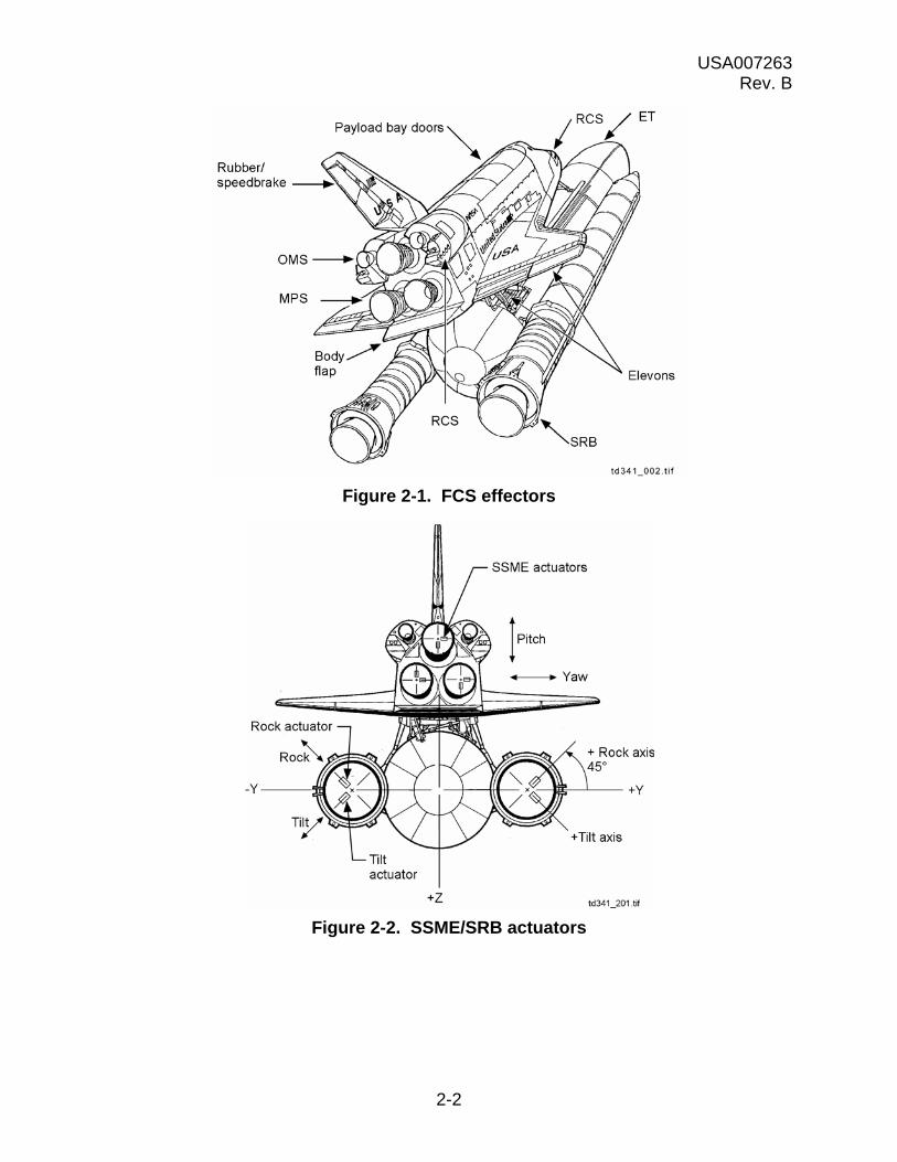
To meet its objectives of providing vehicle control during dynamic flight, the space shuttle’s flight control system uses several means. Figure 2-1 shows you most of them and where they are located.
During ascent, the shuttle Main Propulsion System (MPS) engines and/or the SRB nozzles are gimbaled (pivoted) to provide attitude and flightpath control. Figure 2-2 shows the location of the nozzles and the actuators that move them. During first-stage flight, the SRB nozzles provide nearly all the steering, and the orbiter is pitched, yawed, or rolled by mixing their rock and tilt movements. After SRB separation, the orbiter is steered by gimbaling its main engines. The engines can maintain adequate control as long as at least two of them are running. If only one main engine remains, it will handle pitch and yaw. Roll control will be handled by the RCS. The only aerosurfaces active during ascent are the elevons, and they are used only for load relief.
During entry, the RCS is used in conjunction with the aerosurfaces until the dynamic pressure builds up so that the aerosurfaces alone can handle the job (see Figure 2-1.) The Body Flap (BF) is used primarily for pitch trim, while the elevons are used for pitch and roll control. Above Mach 10, the speedbrake is commanded closed. From Mach 10 to Mach 3.2, the speedbrake is opened to provide pitch trim. At Mach 5, the rudder becomes active. The rudder is assisted by RCS jets until Mach 1.0, after which the rudder alone is used to yaw the vehicle. The speedbrake continues to control pitch modulation until 0.9 Mach, when it is actively used to control drag; i.e., energy. At main gear touchdown, the speedbrake is commanded full open to provide a nose-up pitching moment that will aid nose derotation.
USA007263 Rev. B
2-2
Figure 2-1. FCS effectors
Figure 2-2. SSME/SRB actuators

USA007263 Rev. B
2-3
2.2 CREW CONTROLS
Whether during ascent or entry, the vehicle may be flown automatically or manually. Manual commands are sent from the flight crew’s controllers to the GPCs. From there they go to either the Ascent Thrust Vector Control (ATVC) system or to the Aerosurface Servoamplifiers (ASAs), depending on the phase of flight (see Figure 2-3). Primary crew controls are the Rotational Hand Controllers (RHCs), the Speedbrake/Thrust Controllers (SBTCs), and the Rudder Pedal Transducer Assemblies (RPTAs). The BF switch can be used to manually command BF position.
Figure 2-3. Crew controls

USA007263 Rev. B
2-4
Also important are the FCS, ASA, and ATVC power switches. The four FCS channel switches are on Panel C3. The four ASA power switches are scattered across Panels O14, O15, and O16, while the four ATVC power switches are on Panel O13. Normally during dynamic flight, the crew will interface only with the FCS switches on Panel C3. A simplified schematic showing how these switches are linked is shown in Figure 2-4.
Figure 2-4. FCS/ASA/ATVC switches
2.3 CREW DISPLAYS
Foremost in the crew displays is the Caution and Warning (C&W) annunciator panel. If an FCS message is generated by either an ATVC or an ASA problem, it will be accompanied by a BACKUP C&W ALARM light, an FCS CHANNEL light, and a class 2 alarm. If an aerosurface saturates in either position or hinge moment, FCS SATURATION and BACKUP C&W ALARM lights will be illuminated and a class 2 alarm sounded. Figure 2-5 illustrates the position of these lights within the C&W matrix. The C&W annunciator panel is located in the center top of the orbiter cockpit Panel F7.
The Surface Position Indicator (SPI) can be shown on any Multifunction Electronic Display Subsystem (MEDS) Multifunction Display (MFD). The SPI presents an analog readout of aerosurface position. For the speedbrake, it shows both commanded and actual position. The SPI works in OPS 3, MM602, and MM603 (see Figure 2-6).
td341_204.cnv
CNTLbus
FCS
AUTO
OFF
ATVC
ON
OFF
ASA
ON
OFF
CNTL bus
CNTL bus
ASA black box
ATVC black box
CNTL bus
CNTL bus
CNTLbus
CNTLbus

USA007263 Rev. B
2-5
Figure 2-5. C&W annunciator panel
Figure 2-6. SPI display
2.4 GNC/BFS SYS SUMM 1
GNC SYS SUMM 1 is available in all OPS. A small portion of it is dedicated to aerosurface position and FCS channel status. If an FCS channel message is issued, an arrow will appear underneath the appropriate channel number (refer to Figure 2-7).
TD3410205.PNL;1
-30
TE UP
ELEVONSDEG
BODY FLAP%
-20
-10
0
+10
+20
TE DN
30 20 10 0 10 20 30RUDDER-DEG
L RUD R RUD
5 0 5AILERON-DEG
L AIL R AIL
0 20 40 60 80 100XXX
XXX
SPEEDBRAKE %ACTUAL
COMMAND
0
20
40
60
100
80
td341_007.cnv

USA007263 Rev. B
2-6
Figure 2-7. GNC SYS SUMM 1 display
2.5 SPEC 53, CONTROLS
Figure 2-8 shows SPEC 53, CONTROLS. This display is available in OPS 1, 6, and 3. Using this panel, the crew can check the aerosurface secondary actuator port status, bypass or reset ports, and check or deselect aerosurface position feedbacks.
Figure 2-8. CONTROLS display
USA007263 Rev. B
2-7
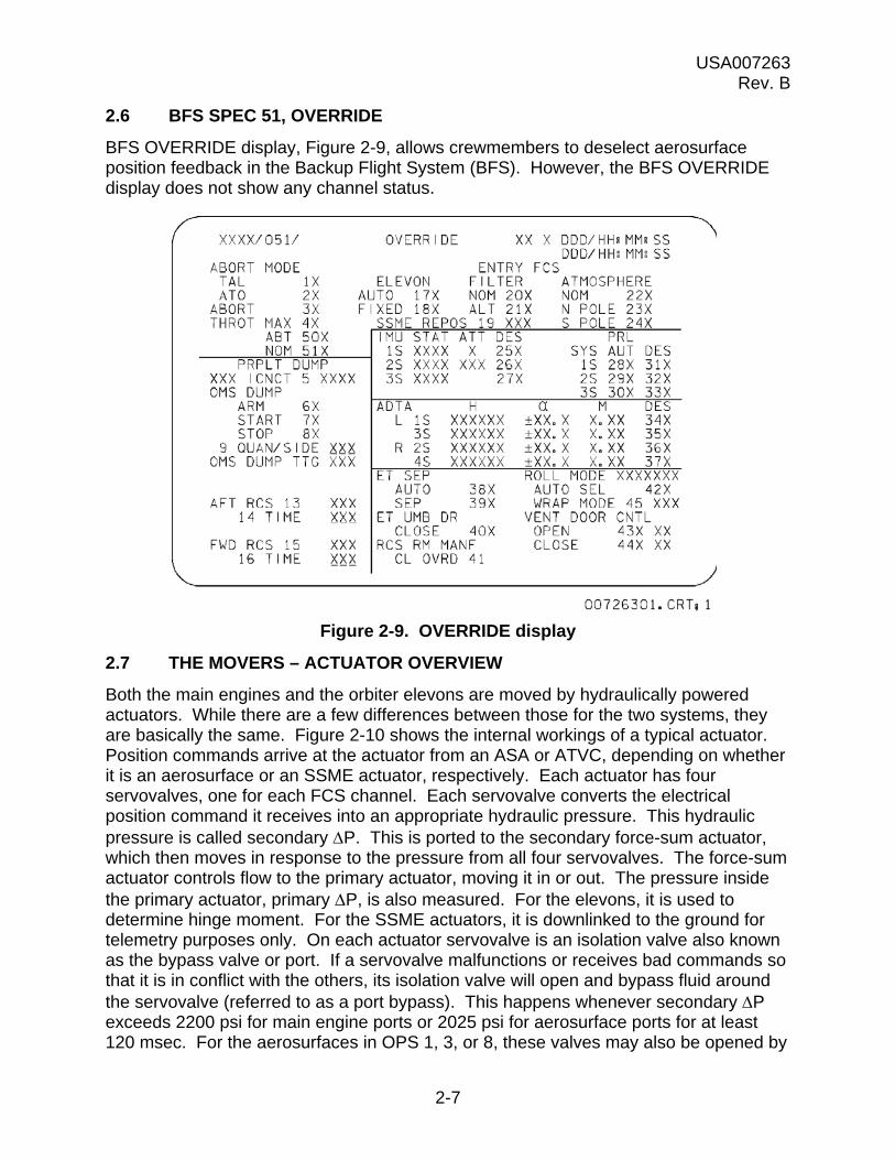
2.6 BFS SPEC 51, OVERRIDE
BFS OVERRIDE display, Figure 2-9, allows crewmembers to deselect aerosurface position feedback in the Backup Flight System (BFS). However, the BFS OVERRIDE display does not show any channel status.
Figure 2-9. OVERRIDE display
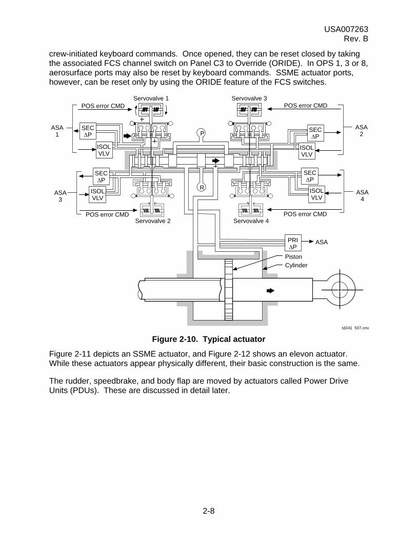
2.7 THE MOVERS – ACTUATOR OVERVIEW
Both the main engines and the orbiter elevons are moved by hydraulically powered actuators. While there are a few differences between those for the two systems, they are basically the same. Figure 2-10 shows the internal workings of a typical actuator. Position commands arrive at the actuator from an ASA or ATVC, depending on whether it is an aerosurface or an SSME actuator, respectively. Each actuator has four servovalves, one for each FCS channel. Each servovalve converts the electrical position command it receives into an appropriate hydraulic pressure. This hydraulic pressure is called secondary P. This is ported to the secondary force-sum actuator, which then moves in response to the pressure from all four servovalves. The force-sum actuator controls flow to the primary actuator, moving it in or out. The pressure inside the primary actuator, primary P, is also measured. For the elevons, it is used to determine hinge moment. For the SSME actuators, it is downlinked to the ground for telemetry purposes only. On each actuator servovalve is an isolation valve also known as the bypass valve or port. If a servovalve malfunctions or receives bad commands so that it is in conflict with the others, its isolation valve will open and bypass fluid around the servovalve (referred to as a port bypass). This happens whenever secondary P exceeds 2200 psi for main engine ports or 2025 psi for aerosurface ports for at least 120 msec. For the aerosurfaces in OPS 1, 3, or 8, these valves may also be opened by
USA007263 Rev. B
2-8
crew-initiated keyboard commands. Once opened, they can be reset closed by taking the associated FCS channel switch on Panel C3 to Override (ORIDE). In OPS 1, 3 or 8, aerosurface ports may also be reset by keyboard commands. SSME actuator ports, however, can be reset only by using the ORIDE feature of the FCS switches.
Figure 2-10. Typical actuator
Figure 2-11 depicts an SSME actuator, and Figure 2-12 shows an elevon actuator. While these actuators appear physically different, their basic construction is the same.
The rudder, speedbrake, and body flap are moved by actuators called Power Drive Units (PDUs). These are discussed in detail later.
ASA1
ASA3
ASA2
ASA4
POS error CMD
POS error CMD
POS error CMD
POS error CMD
Servovalve 1 Servovalve 3
Servovalve 2 Servovalve 4
ISOLVLV
ISOLVLV
ISOLVLV
ISOLVLV
SECP
SECP
SECP
SECP
PRIP
P
R
PistonCylinder
td341_507.cnv
ASA

USA007263 Rev. B
2-9
Figure 2-11. Main engine electrohydraulic servoactuator (exterior
physical characteristics)
Figure 2-12. Elevon actuator
Servovalve housing
Tail stock(thrust structure)
Cylinder andpiston assembly
Piston rod end(main engine)
td341_210.cnv

USA007263 Rev. B
2-10
2.8 QUESTIONS
1. During first-stage flight, what provides the major portion of vehicle steering? During second stage?
2. During entry, what is the BF used for?
3. List the uses of the speedbrake during entry.
4. Where can the crew see aerosurface positions?
5. What does a servovalve do?
6. What is secondary P?
7. What happens if secondary P exceeds 2200 psi for main engine ports or 2025 psi for aerosurface ports longer than 120 msec?
8. How can an actuator isolation valve be reset for
(a) An SSME actuator
(b) An aerosurface actuator

USA007263 Rev. B
3-1
3.0 ATVC SYSTEM
During ascent, the orbiter is steered by gimbaling the SRB nozzles and/or the SSMEs. Steering commands may originate from the crew or auto guidance, but in either case, they go from the GPCs through a Flight Aft (FA) Multiplexer/Demultiplexer (MDM) to the ATVCs. The ATVCs then forward the commands to the appropriate actuators. Figure 3-1 illustrates that signal flow.
Figure 3-1. ATVC command flow
Power to the ATVCs is controlled through both the FCS and ATVC switches, as shown in Figure 3-2. Consider the FCS switch first. Each one of its three contacts is powered from a different control bus. Two of the contacts supply control bus power to the ATVC switch.
SRB
SSME
ToSRB
ACTR
ATVC no. 1
GPC 1
FCSMPSTVCSOP
FC5 FA-1MDM
SRBdriver
12
34
MPSdriver
12
34
56
Pitch
Rightengine
Yaw
Centerengine
Pitch
Leftengine
Yaw
Pitch
Yaw
td341_014.cnv
ATVCno. 2
ATVCno. 3
ATVCno. 4
FA-2MDM
FA-3MDM
FA-4MDM
FC6
FC7
FC8
GPC 2
GPC 3
GPC 4

USA007263 Rev. B
3-2
Figure 3-2. FCS/ATVC switch power
Two of the ATVC switch contacts, in turn, supply this control bus power to the Remote Power Controllers (RPCs). The third ATVC switch is powered by a separate control bus whose power is routed to the RPC that controls the isolation valve driver. This was done so that with the ATVCs on, if an FCS channel switch was turned off, power would still remain to bypass ports and prevent a force fight with the other channels. (A force fight occurs when one or more of the actuator servovalves tries to command the actuator to a position different than the others.) Turning an ATVC switch off will completely interrupt both internal and isolation valve power to the ATVC and the ports will not bypass, causing a force fight with the servovalves assigned to the other channels. To operate the system nominally, the FCS switches must be in AUTO or override, and the ATVC switches must be on. Flow of control bus power through the FCS switches is identical in either the AUTO or ORIDE position, with the exception that the ORIDE position sends a triple-redundant discrete to Guidance, Navigation, and Control (GN&C) switch RM that will be forwarded to the ATVC black box.
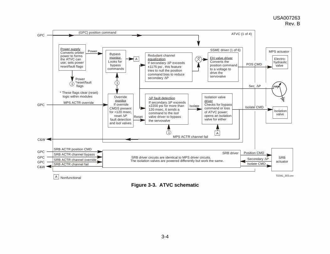
The vehicle has four ATVCs, each one connected via an FA MDM to a dedicated FCS channel. Figure 3-3 shows the basic components of each ATVC to be an internal power supply and 10 circuit cards, called drivers. The internal power supply converts orbiter power to forms the drivers can use, monitors itself for proper operation, and sets power reset/fault flags if it detects a problem. The drivers process MPS/SRB gimbal
FF2
TD341_302.cnv
AUTO
Override
OFF OFF
ON
ASA
FF3CA2
ORIDE
FF1
CA1
ASA
MNB
ATVC power
Isolationvalvedriver
MNC
MNA
ATVC power
BC1
AB1ORIDE
ORIDE
ATVC switchFCS switch
PNL C3 PNL O17
RPC
RPC
RPC
USA007263 Rev. B
3-3
commands, monitor secondary P, and isolate or reset ports as necessary. Six of the drivers are assigned to the MPS actuators (one for pitch and one for yaw on each engine), and four control the SRB nozzle actuators (one rock and one tilt on each nozzle).
USA007263 Rev. B
3-4
Figure 3-3. ATVC schematic
TD341_303.cnv
+
SSME driver (1 of 6) MPS actuator
Electro-hydraulic
valve
Isolationvalve
MPS ACTR overrideIsolate
SRB driver
(GPC) position command
SRB ACTR position CMD
Overridemonitor
If overrideCMDS presentfor >120 msec,
reset Pfault detectionand isol valves
Redudant channelequalizationIf secondary P exceeds±1175 psi , this featuretries to null the positioncommand bias to reducesecondary P
EH valve driverConverts theposition commandto a voltage todrive theservovalve
Isolation valvedriverChecks for bypasscommand or lossof ATVC power;opens an isolationvalve for either
Bypassmonitor
Looks forbypass
commands
A
Power
Power*reset/faultflags
1
* These flags clear (reset)logic within modules
Power supplyConverts orbiterpower to formsthe ATVC canuse; sets powerreset/fault flags
P fault detectionIf secondary P exceeds±2200 psi for more than120 msec, it sends acommand to the isolvalve driver to bypassthe servovalve
1
ATVC (1 of 4)
MPS ACTR channel fail
C&W
GPC
GPCSRB ACTR channel bypass
SRB ACTR channel overrideSRB ACTR channel fail
SRBactuator
SRB driver circuits are identical to MPS driver circuits.The isolation valves are powered differently but work the same.
Isolate CMD
POS CMD
Sec P
A1
Isolate CMD
Secondary P
Position CMD
Reset
GPC
GPC
C&W
GPC
A Nonfunctional

USA007263 Rev. B
3-5
3.1 MPS DRIVERS
An MPS driver consists of a bypass monitor, P fault detection logic, redundant channel equalization logic, an override monitor, an Electrohydraulic (EH) valve driver circuit, and an isolation valve driver circuit.
The bypass monitor was originally designed to receive bypass commands from crew-initiated keyboard entries. This capability was never implemented, however, and this module is inoperative.
The P fault detection module monitors secondary P within its assigned servovalve. If it detects secondary P exceeding 2200 psi for more than 120 msec as determined by the secondary P counter, it issues a discrete to the isolation valve driver to bypass the port. (The counter increments 1 second for each second that secondary P is greater than 2200 psi and decrements at 1/2 second for each second that secondary P is less than 2200 psi, as shown in Figure 3-4.) This module also looks for power reset/fault signals from the ATVC power supply, clearing the counter for signals greater than 120 msec in duration.
Figure 3-4. ATVC fault detection time counter
� 2200
0 msec
0 msec
50
50
100
100
150
150
200
200
250
250
300
300
350
350
120
100
80
60
40
20
td341a_403aTime (msec)
P C
oun
ter
(mse
c)S
eco
nda
ry
P (
psi)
USA007263 Rev. B
3-6
Redundant channel equalization also monitors secondary P. If secondary P exceeds 1175 psi, redundant channel equalization will try to bias the actuator command over an 8-second interval to reduce the force fight.
The override monitor looks for override commands. If it detects one lasting for more than 120 msec, it will reset bypassed ports and override P fault detection logic.
The EH valve driver converts the actuator command from the GPCs into a proportional voltage sent to the actuator servovalves.
The isolation valve driver looks for a bypass command from the bypass monitor, P fault detection, or from within itself. It will issue a bypass command for loss of ATVC internal power. The isolation (bypass) command bypasses the actuator port and sends an MPS actuator channel fail flag back to the GPC, which will respond with an FCS CH X message.
The best way to understand how all this works together is to go through its operation in detail.
During Ascent, the GPCs determine that they need to pitch the C SSME a little. They issue a 2 pitch command. This command, via FAs 1 through 4 and the respective FCS channels, goes to each ATVC. Inside each ATVC, the command goes to the C SSME pitch driver. There, it travels to the EH valve driver. So far, everything is operating fine, so redundant channel equalization is not required to bias the command.
The EH valve driver changes the command to a proportional current that it sends to its actuator servovalve. This moves the servovalve, which ports hydraulic pressure to the secondary force-sum actuator. When the secondary actuator moves, it ports hydraulic pressure to the primary actuator to move it.
Secondary P in servovalve 3 begins to climb. When the servovalve reaches 1175 psi, redundant channel equalization tries to drive it back down by adding a bias to the command. The effort fails and the pressure continues to climb. Delta P fault detection determines that it is climbing past 2200 psi for more than 120 msec and sends an isolation command. The isolation valve driver recognizes the isolation command and opens the isolation valve (bypasses the port). This also sends back a discrete to the GPC, which will issue an FCS CH 3 message and put a down arrow on GNC SYS SUMM 1. The override monitor does not detect any override commands, so it does not reset the port or the fault detection logic.
ATVC 2 begins to develop a problem. Its power supply malfunctions and its 15 V dc internal power supply fails. Each isolation valve driver isolates the associated ports, generating FCS CH 2 messages and down arrows.
Since this was the second failure, the crew will take FCS channel switches 1 and 4 to ORIDE per procedure. The override monitors in ATVCs 1 and 4 see the override
USA007263 Rev. B
3-7
commands and override P fault detection within themselves. Therefore, on channels 1 and 4, no ports will bypass no matter what the secondary P becomes.
3.2 SRB DRIVERS
The SRB drivers are the same as the MPS system, except that their isolation valves are powered through RPCs controlled by the Master Event Controllers (MECs).
For more detailed information in regards to ATVC, please consult the MPS TVC Workbook 21002 (USA006502).

USA007263 Rev. B
3-8
3.3 QUESTIONS
1. What components make up the black box known as an ATVC?
2. What is redundant channel equalization?
3. How does P fault detection work?
4. How does the override monitor work?

USA007263 Rev. B
4-1
4.0 ASA SYSTEM
The part of the FCS system that controls the aerosurfaces is usually referred to as the ASA system. During ascent, its only function is to perform load relief, but during entry, it is the primary system for vehicle control.
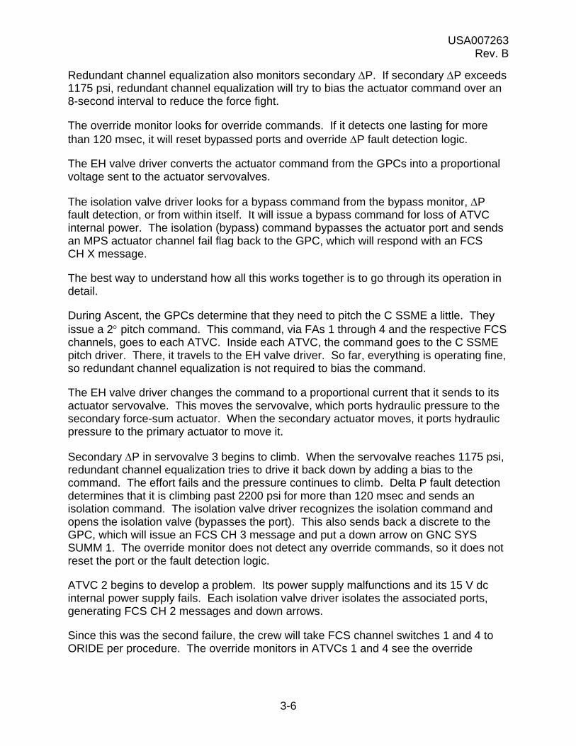
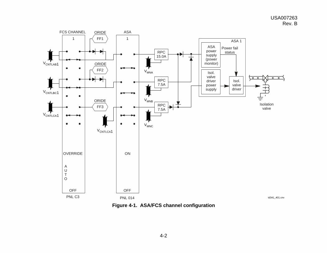
The ASAs are actually the four black boxes that serve as the “brains” of the FCS. Each ASA is assigned to a respective FCS channel, ASA 1 to FCS CH1, etc. Power to the ASA is controlled through both the FCS and the ASA power switches. Figure 4-1 shows how the power is routed. The ASA receives main bus power from three different buses. One of the buses powers the ASA isolation valve driver, while the other two go to the ASA internal power supply. These latter two are routed through the FCS channel switch. This was done so that if an FCS channel switch is turned off, the ASA isolation valve driver is still powered and will isolate the system by bypassing ports. If an ASA switch is turned off, however, the ports cannot bypass, because this would interrupt ASA isolation valve power. In this case, its servovalves will be driven to a null position and will fight with those on the other channels.
How does the ASA work? It takes a lot of data. It looks for bypass, override, and aerosurface position commands from the GPCs (Figure 4-2). Bypass commands trigger an isolation command to an aerosurface actuator, while an override command takes it away. Aerosurface position commands are summed with primary P and position feedbacks from the actuators to generate a position error command. It is this position error command that the ASA sends to the actuator servovalve to make the aerosurface move. The ASA also monitors secondary P from the actuators and, if it gets too high (2025 psi for 120 msec), will issue an isolation command to a servovalve port. When a servovalve bypasses, the ASA sends back to the GPC an actuator channel fail discrete that generates an FCS CH X message to the crew. In addition, the ASA also sends back primary P and position feedbacks to the GPCs, which use them later for C&W and other purposes. The ASA does all this by utilizing a power supply, six drivers (one for each elevon, one for the rudder, and one for the speedbrake), and a circuit for the BF. In ASAs 1, 2, and 3, the BF circuit issues commands and also receives position feedbacks. The BF circuit in ASA 4, however, receives feedbacks only.
USA007263 Rev. B
4-2
Figure 4-1. ASA/FCS channel configuration
FCS CHANNEL
OVERRIDE
OFF
PNL C3
ON
OFF
PNL 014
1 1
ASAORIDE
FF1
FF2
RPC15.0A
RPC7.5A
ASA 1
ASApowersupply(power
monitor)
Power failstatus
Isol.valvedriverpowersupply
Isol.valvedriver
Isolationvalve
ORIDE
ORIDE
td341_401.cnv
RPC7.5A
AUTO
VCNTLAB1
VCNTLBC1
VCNTLCA1
VCNTLCA1
VMNC
VMNB
VMNA
FF3

USA007263 Rev. B
4-3
Figure 4-2. ASA description
4.1 ELEVON DRIVERS
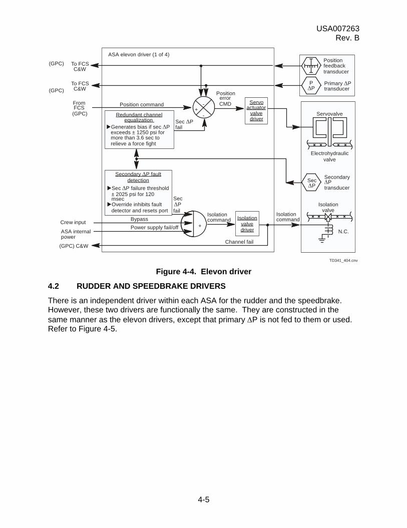
The elevon drivers receive from their respective elevons a position feedback, primary P, and secondary P. They receive from the GPCs elevon position commands. Each driver sums position feedback, primary P, and the GPC-issued position command to determine a position error command. It is the position error command that is sent to the servovalve and moves the elevon.
The drivers monitor secondary P to detect developing problems. If secondary P exceeds 1250 psi for more than 3.6 seconds, a feature called redundant channel equalization will bias the position command to reduce the pressure. Secondary P fault detection will track the pressure, and when 2025 psi is exceeded for more than 120 msec as determined by the secondary P counter, it issues a discrete to the isolation valve driver to bypass the port. (The counter increments 1 second for each second that secondary P is greater than 2025 psi and decrements 1/4 second for each second that secondary P is less than 2025 psi, as shown in Figure 4-3.) The isolation command travels to an isolation valve on the appropriate servovalve. The isolation valve will open, bypassing hydraulic pressure to the servovalve and sending secondary P to zero. This resets the secondary P logic counter to zero. The driver will also bypass a port if it receives bypass commands from the crew, which they may issue via SPEC 53 or the FCS checkout dedicated display, or if it receives a power supply off/fail flag from the ASA internal power supply. All these actions are geared toward keeping a bad servovalve from fighting with the good ones.
TD341_402.cnv
POS CMDS
Bypass CMDS
Override CMDS
Primary P
POS feedback
Actuatorchannel fail
POS error CMD
Isolation CMD
Primary P
POS feedback
Secondary P
• Derives an actuator position error command,based upon control system commandsbeing summed with actuator feedback signals.
• Performs fault detection, based uponsecondary P.
Actuators
GPC
Aerosurface amplifier

USA007263 Rev. B
4-4
Figure 4-3. Fault detection time counter curve
Figure 4-4 shows the signal flow to and from an elevon driver and the processing inside. Notice that primary P and position feedbacks are used to bias the position command and also go back to the GPCs. Primary P is used by the GPC to calculate elevon hinge moment. Position feedback is used by the GPCs for flight control purposes. If either of these gets too large, the GPCs will issue an FCS SAT X message where X is either POS or MOM, depending on whether it was position feedbacks or hinge moment, respectively. A down arrow will also appear next to the affected aerosurface on GNC SYS SUMM 1 under the SURF heading.
± 2025
0 msec
0 msec
50
50
100
100
150
150
200
200
250
250
300
300
350
350
120
100
80
60
40
20
td341_403.cnv
Time (msec)
USA007263 Rev. B
4-5
Figure 4-4. Elevon driver
4.2 RUDDER AND SPEEDBRAKE DRIVERS
There is an independent driver within each ASA for the rudder and the speedbrake. However, these two drivers are functionally the same. They are constructed in the same manner as the elevon drivers, except that primary P is not fed to them or used. Refer to Figure 4-5.
Isolationvalvedriver
Servoactuator
valvedriver
SecPfail
Generates bias if sec Pexceeds ± 1250 psi formore than 3.6 sec torelieve a force fight
To FCSC&W
ASA elevon driver (1 of 4)
FromFCS
(GPC)
Crew input
ASA internalpower
(GPC)
(GPC)
(GPC) C&W
Position command
Redundant channelequalization
Sec P failure threshold± 2025 psi for 120msec
Override inhibits faultdetector and resets port
PositionerrorCMD
Secondary P faultdetection
Sec Pfail
Power supply fail/off
Isolationcommand
Channel fail
Isolationcommand
Positionfeedbacktransducer
Servovalve
Electrohydraulicvalve
SecondaryPtransducer
N.C.
Isolationvalve
Bypass+
+-
-
TD341_404.cnv
Primary Ptransducer
PP
SecP
To FCSC&W

USA007263 Rev. B
4-6
Figure 4-5. Rudder/speedbrake driver
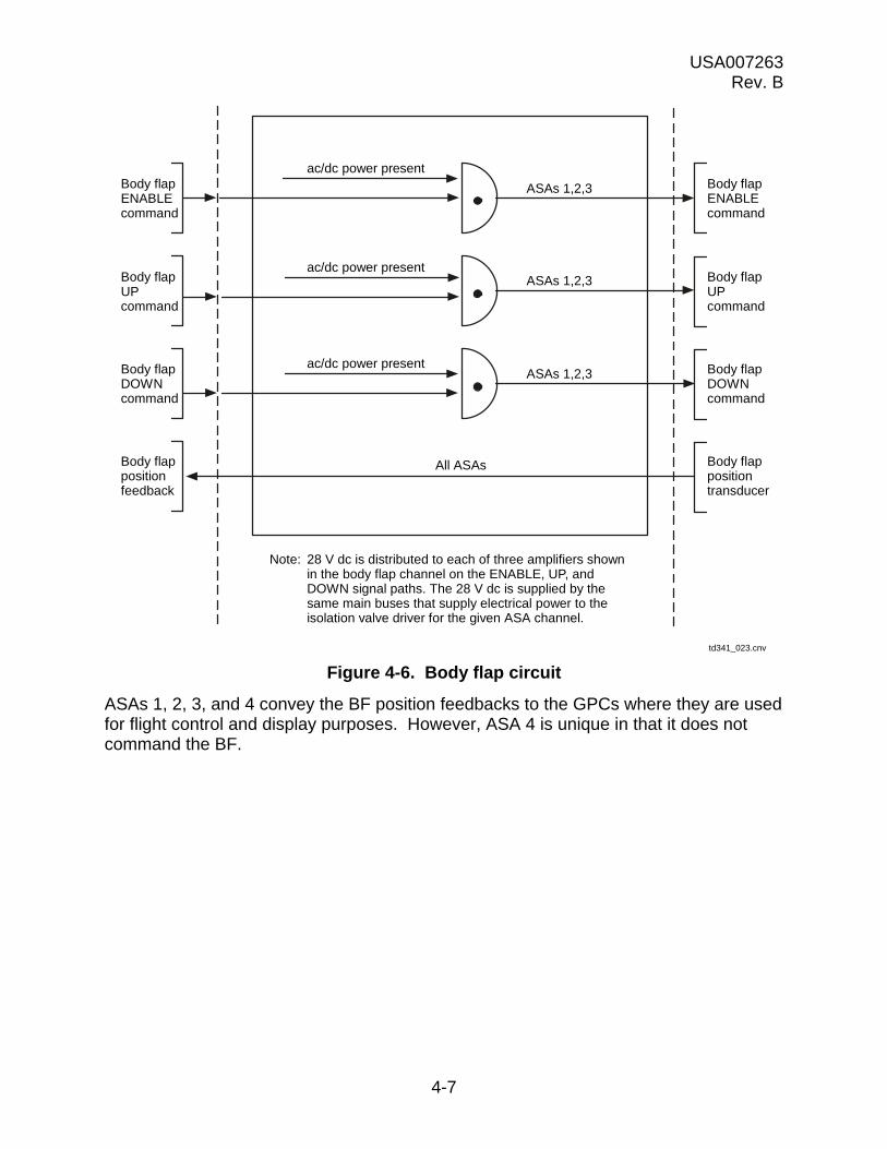
4.3 BODY FLAP
The BF circuit is significantly different from the drivers for the other aerosurfaces. (See Figure 4-6)
The channels in ASAs 1, 2, and 3 accept the GPC commands that move the BF. These commands consist of a BF ENABLE command and a directional (UP or DOWN) command. These commands are presented at AND gates. If the command and a signal from the ASA power supply is present, the command is allowed to pass.
Isolationvalvedriver
Servoactuatorvalvedriver
SecPfail
Generates bias if sec Pexceeds ± 1250 psi formore than 3.6 sec torelieve a force fight
To FCSC&W
ASA rudder driver
FromFCS
(GPC)
Override
Crew input
ASA internalpower
(GPC)
(GPC)
(GPC) C&W
Position command
Redundant channelequalization
Sec P failure threshold± 2025 psi for 120msec
Override inhibits faultdetector and resets port
PositionerrorCMD
Secondary P faultdetection
Sec Pfail
Power supply fail/off
Isolationcommand
Channel fail
Isolationcommand
Positionfeedbacktransducer
Servovalve
Electrohydraulicvalve
SecP
SecondaryPtransducer
N.C.
Isolationvalve
Bypass+
+-
-
TD341_405.cnv
USA007263 Rev. B
4-7
Figure 4-6. Body flap circuit
ASAs 1, 2, 3, and 4 convey the BF position feedbacks to the GPCs where they are used for flight control and display purposes. However, ASA 4 is unique in that it does not command the BF.
Body flapENABLEcommand
Body flapUPcommand
Body flapDOWNcommand
Body flappositionfeedback
ac/dc power present
ac/dc power present
ac/dc power present
ASAs 1,2,3
ASAs 1,2,3
ASAs 1,2,3
Body flapENABLEcommand
Body flapUPcommand
Body flapDOWNcommand
Body flappositiontransducer
All ASAs
Note: 28 V dc is distributed to each of three amplifiers shownin the body flap channel on the ENABLE, UP, andDOWN signal paths. The 28 V dc is supplied by thesame main buses that supply electrical power to theisolation valve driver for the given ASA channel.
td341_023.cnv

USA007263 Rev. B
4-8
4.4 QUESTIONS
1. During ascent, what purpose do the aerosurfaces serve?
2. How many control buses are routed through the ASA power switch?
3. What does turning off an FCS CH switch do?
4. What components make up an ASA?
5. What will trigger redundant channel equalization?
6. If, in question 5 above, secondary P continued to rise, what would happen?
7. What is elevon primary P and how is it used?
8. How are the rudder and speedbrake drivers different from the elevon drivers?
9. How is the BF circuit for ASA 4 different from the other ASAs?

USA007263 Rev. B
5-1
5.0 AEROSURFACES
5.1 ELEVONS
The word elevon is a composite of the two words “elevator” and “aileron.” On an aircraft, the elevator is usually located on or near the tail and pitches the nose up and down. The ailerons are located on the wings and deflect differentially (one up and one down) to roll the aircraft. On the shuttle, the four elevons located on the trailing edge of its wings perform both these functions.
The elevons also do something not done on a standard aircraft. During ascent, the shuttle accelerates through the lower atmosphere very quickly, which imposes high loads on the wings. The elevons are deflected to try to reduce the loads. In this scheme, inboard elevons are deflected together, as are the outboards. The elevons will stay on the I-loaded schedule unless primary P goes out of limits. The elevons will then be driven to return the primary P inside the limits. The elevons will then pick up the schedule again. By the time the vehicle reaches about Mach 2.5, the elevons have all reached a null position, where they remain.
Figure 5-1 illustrates how the elevons work.
Figure 5-1. Elevon functions
Aileron action
Elevon functions
Elevator action
Roll
The right elevon up and the leftelevon down causes right roll.
The left elevon up and rightelevon down causes left roll.
Pitch
Both elevons up causes nose up pitch.
Both elevons down causes nose down pitch.
Load relief
The inboard panels deflect together.
The outboard panels deflect together.
td341_024.cnv

USA007263 Rev. B
5-2
Each of the four elevons is moved by a hydraulically powered servoactuator. (Refer to Figure 2-11) Each servoactuator is located in the wing at the center of the corresponding elevon. The inboard and outboard actuators perform the same functions; however, the outboard actuators are physically shorter due to a lack of space there. Hydraulic power to each servoactuator can be supplied by any of the orbiter’s three hydraulic systems. A switching valve controls which hydraulic system provides the power.
Each switching valve receives hydraulic power from all three systems. Each system is assigned as the primary, standby 1, or standby 2. Figure 5-2 shows how the systems are hooked up. How each system is assigned (primary, etc.) varies from elevon to elevon. As you can see, there are actually two valves in the switching valve assembly. The first valve takes power from the primary and standby 1 systems. As long as primary pressure is up, the first valve outputs primary pressure to the second. If primary pressure drops to less than 1200 to 1500 psia, pressure from the standby 1 system will shuttle the valve downward so that its pressure will be output from the first valve. In the second valve, pressure from the first valve is pitted against that from standby 2. Whichever system has the higher pressure becomes the controlling system output by the second valve. In this fashion, a failing system is always replaced by one that is good.
The valves will also ensure that hydraulic return is directed to the controlling system. Valve position is monitored by a Linear Variable Differential Transformer (LVDT) and sent to downlink telemetry.
Now that we see how the switching valves get hydraulic power to the elevons, we will look at the elevon actuators themselves. Refer to Figure 5-3.
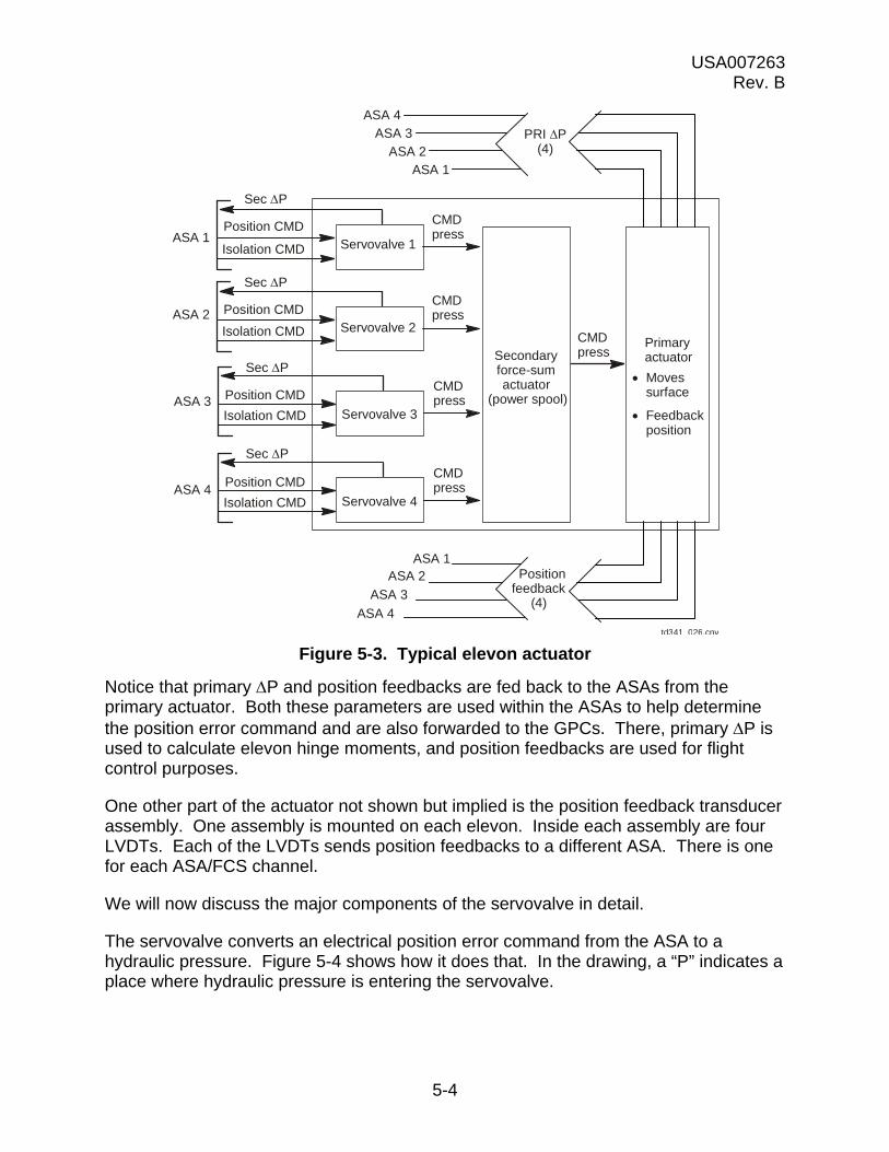
The elevon actuators are composed of four servovalves, a secondary force-sum actuator, and a primary actuator. Each servovalve is assigned to a different ASA and, thereby, a different FCS channel. Each converts an electrical position command from the ASA to a hydraulic pressure. This pressure is ported to the secondary force-sum actuator, also known as the power spool. The four hydraulic pressures each help move a valve within the spool that controls hydraulic pressure to the primary actuator. This latter pressure is what moves the ram within the primary actuator, resulting in aerosurface movement.
If a problem develops within a servovalve or if it is commanded to a position different from that of the other servovalves within an actuator, secondary P should begin to rise. When the ASA detects secondary P at or above 2025 psi for more than 120 msec, it will send an isolation command to the servovalve. This will open the isolation valve, bypassing hydraulic pressure to the servovalve and causing its commanded pressure to the power spool to drop to zero. The bad servovalve is effectively removed from the operation.

USA007263 Rev. B
5-3
Figure 5-2. Switching valve
LVDT LVDT
PS2
PS1
PP
RP
RS1
RS2
P To actuator
R From actuator
To telemetry
PP Primary pressureRP Primary return
PS1 Standby 1 pressureRS1 Standby 1 return
PS2 Standby 2 pressureRS2 Standby 2 return
td341_025.cnv
USA007263 Rev. B
5-4
Figure 5-3. Typical elevon actuator
Notice that primary P and position feedbacks are fed back to the ASAs from the primary actuator. Both these parameters are used within the ASAs to help determine the position error command and are also forwarded to the GPCs. There, primary P is used to calculate elevon hinge moments, and position feedbacks are used for flight control purposes.
One other part of the actuator not shown but implied is the position feedback transducer assembly. One assembly is mounted on each elevon. Inside each assembly are four LVDTs. Each of the LVDTs sends position feedbacks to a different ASA. There is one for each ASA/FCS channel.
We will now discuss the major components of the servovalve in detail.
The servovalve converts an electrical position error command from the ASA to a hydraulic pressure. Figure 5-4 shows how it does that. In the drawing, a “P” indicates a place where hydraulic pressure is entering the servovalve.
ASA 4ASA 3
ASA 2ASA 1
PRI P(4)
td341 026.cnv
ASA 1
Sec P
Position CMD
Isolation CMD Servovalve 1
CMDpress
ASA 2
Sec P
Position CMD
Isolation CMD Servovalve 2
CMDpress
ASA 3
Sec P
Position CMD
Isolation CMD Servovalve 3
CMDpress
ASA 4
Sec P
Position CMD
Isolation CMD Servovalve 4
CMDpress
CMDpressSecondary
force-sumactuator
(power spool)
Primaryactuator
Movessurface
Feedbackposition
ASA 1ASA 2
ASA 3
ASA 4
Positionfeedback
(4)

USA007263 Rev. B
5-5
Figure 5-4. Servovalve schematic
An “R” shows where hydraulic fluid is leaving the servovalve to return to the orbiter hydraulic system. Hydraulic pressure enters the servovalve in four places, namely at the ports marked P1 and P2. The fluid going to P1 is passed through a restrictor, which lowers its pressure so that P1 < P2. This fluid flows out the orifices to the central cavity and back down to the servovalve spool . This happens on both sides of the flapper valve so that all the pressures on the spool are equal. P2 supplies drive pressure to move the secondary force-sum actuator. With the servovalve in its neutral position, this drive pressure is blocked. The secondary force-sum actuator does not move.
Notice that the isolation valve is connected to the hydraulic flow to the secondary actuator. If the secondary P (this is the pressure from the servovalve to the secondary actuator) goes above 2025 psi, the ASA opens the valve. This will port the fluid straight back to the orbiter hydraulic system, essentially removing the servovalve from operation.
Figure 5-5 shows how the servovalve works. In this instance, the ASA has sent out a positive voltage as a position error command, which causes the flapper valve to torque right. The end of the flapper then blocks the leftmost orifice into the central cavity. This raises the pressure on the left side, which translates to a push on the servovalve spool to the right. Its movement right blocks the leftmost fluid supply and unblocks the
Secondary force - sum actuator
2
ASA
Flapper valve
Centralcavity
P1 1
P2 R
1
R P2
P1
ISOLVLV
3
4
R
R
Otherservovalve td341_504.cnv
1
2
3
4

USA007263 Rev. B
5-6
leftmost fluid return and the fluid supply on the right. Unblocking the latter allows high-pressure fluid to flow to the secondary force-sum actuator, pushing it right. In turn, this ports fluid to the primary ram and causes it to extend, pushing the elevon down.
Figure 5-5. Servovalve operation
Omitted from Figure 5-4 for clarity, but included here, are the feedback wires. One wire runs from each flapper valve to its own servovalve spool. The other runs from the flapper to the secondary actuator. These wires provide an instantaneous mechanical feedback to the flapper. Think of them as springs that try to bring the flappers and valves into alignment at the null position. Though hydraulic forces primarily realign everything when the position error command goes away, these wires start everything moving in the right direction.
There are four servovalves for each elevon, and they all work together to push the secondary force-sum actuator around.
A secondary force-sum actuator is shown in Figure 5-6. The individual servovalve pressures act on the actuator’s ends to push it left or right. Depending upon which way it moves, hydraulic pressure is ported to the front or back side of the primary actuator’s ram. This pushes the primary actuator in or out.
2
ASA
P11
P2 R
1
R P2
P1
ISOLVLV
3
4
R
R
Otherservovalve td341_505.cnv
Feedbackwires
USA007263 Rev. B
5-7
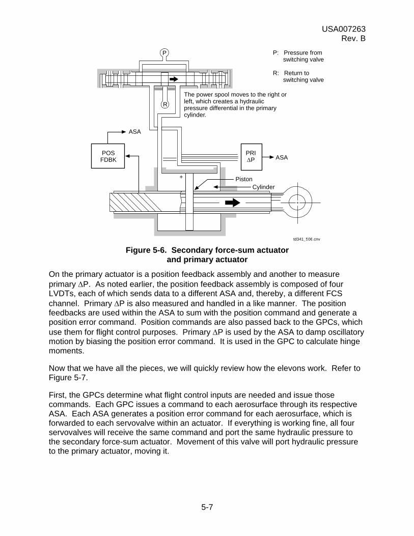
Figure 5-6. Secondary force-sum actuator and primary actuator
On the primary actuator is a position feedback assembly and another to measure primary P. As noted earlier, the position feedback assembly is composed of four LVDTs, each of which sends data to a different ASA and, thereby, a different FCS channel. Primary P is also measured and handled in a like manner. The position feedbacks are used within the ASA to sum with the position command and generate a position error command. Position commands are also passed back to the GPCs, which use them for flight control purposes. Primary P is used by the ASA to damp oscillatory motion by biasing the position error command. It is used in the GPC to calculate hinge moments.
Now that we have all the pieces, we will quickly review how the elevons work. Refer to Figure 5-7.
First, the GPCs determine what flight control inputs are needed and issue those commands. Each GPC issues a command to each aerosurface through its respective ASA. Each ASA generates a position error command for each aerosurface, which is forwarded to each servovalve within an actuator. If everything is working fine, all four servovalves will receive the same command and port the same hydraulic pressure to the secondary force-sum actuator. Movement of this valve will port hydraulic pressure to the primary actuator, moving it.
+
P
R
POSFDBK
ASA
PRIP ASA
CylinderPiston+
The power spool moves to the right orleft, which creates a hydraulicpressure differential in the primarycylinder.
td341_506.cnv
P: Pressure fromswitching valve
R: Return toswitching valve
USA007263 Rev. B
5-8
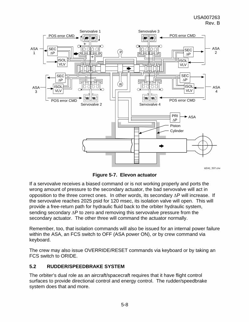
Figure 5-7. Elevon actuator
If a servovalve receives a biased command or is not working properly and ports the wrong amount of pressure to the secondary actuator, the bad servovalve will act in opposition to the three correct ones. In other words, its secondary P will increase. If the servovalve reaches 2025 psid for 120 msec, its isolation valve will open. This will provide a free-return path for hydraulic fluid back to the orbiter hydraulic system, sending secondary P to zero and removing this servovalve pressure from the secondary actuator. The other three will command the actuator normally.
Remember, too, that isolation commands will also be issued for an internal power failure within the ASA, an FCS switch to OFF (ASA power ON), or by crew command via keyboard.
The crew may also issue OVERRIDE/RESET commands via keyboard or by taking an FCS switch to ORIDE.
5.2 RUDDER/SPEEDBRAKE SYSTEM
The orbiter’s dual role as an aircraft/spacecraft requires that it have flight control surfaces to provide directional control and energy control. The rudder/speedbrake system does that and more.
ASA1
ASA3
ASA2
ASA4
POS error CMD
POS error CMD
POS error CMD
POS error CMD
Servovalve 1 Servovalve 3
Servovalve 2 Servovalve 4
ISOLVLV
ISOLVLV
ISOLVLV
ISOLVLV
SECP
SECP
SECP
SECP
PRIP
P
R
PistonCylinder
td341_507.cnv
ASA
USA007263 Rev. B
5-9
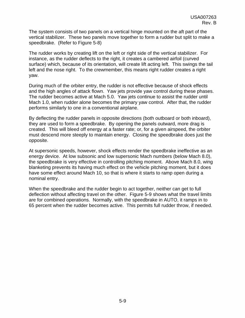
The system consists of two panels on a vertical hinge mounted on the aft part of the vertical stabilizer. These two panels move together to form a rudder but split to make a speedbrake. (Refer to Figure 5-8)
The rudder works by creating lift on the left or right side of the vertical stabilizer. For instance, as the rudder deflects to the right, it creates a cambered airfoil (curved surface) which, because of its orientation, will create lift acting left. This swings the tail left and the nose right. To the crewmember, this means right rudder creates a right yaw.
During much of the orbiter entry, the rudder is not effective because of shock effects and the high angles of attack flown. Yaw jets provide yaw control during these phases. The rudder becomes active at Mach 5.0. Yaw jets continue to assist the rudder until Mach 1.0, when rudder alone becomes the primary yaw control. After that, the rudder performs similarly to one in a conventional airplane.
By deflecting the rudder panels in opposite directions (both outboard or both inboard), they are used to form a speedbrake. By opening the panels outward, more drag is created. This will bleed off energy at a faster rate; or, for a given airspeed, the orbiter must descend more steeply to maintain energy. Closing the speedbrake does just the opposite.
At supersonic speeds, however, shock effects render the speedbrake ineffective as an energy device. At low subsonic and low supersonic Mach numbers (below Mach 8.0), the speedbrake is very effective in controlling pitching moment. Above Mach 8.0, wing blanketing prevents its having much effect on the vehicle pitching moment, but it does have some effect around Mach 10, so that is where it starts to ramp open during a nominal entry.
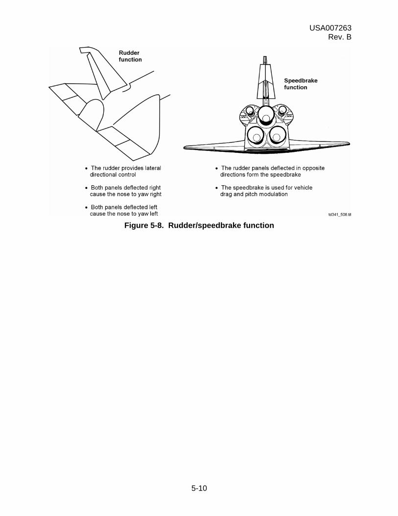
When the speedbrake and the rudder begin to act together, neither can get to full deflection without affecting travel on the other. Figure 5-9 shows what the travel limits are for combined operations. Normally, with the speedbrake in AUTO, it ramps in to 65 percent when the rudder becomes active. This permits full rudder throw, if needed.
USA007263 Rev. B
5-10
Figure 5-8. Rudder/speedbrake function
USA007263 Rev. B
5-11
Figure 5-9. Combined rudder/speedbrake deflection
61.5°
98.6°
The maximum combined rudder andspeedbrake deflection is ± 61.5°
The maximum speedbrakedeflection is 98.6°
The maximum rudder deflection is ± 27.1°td341_509.cnv
For full rudder deflection of ± 27.1°,the speedbrake can open a maximum of68.8° (half angle of 34.4°)
For full speedbrake deflection of 98.6°,(half angle of 49.3°), the rudder can deflect± 12.2°
USA007263 Rev. B
5-12
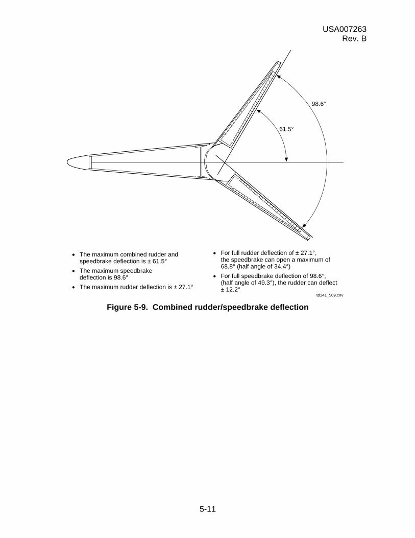
Figure 5-10 shows the mechanical components of the rudder/speedbrake actuator system. A Power Drive Unit (PDU), driven by hydraulic power from the orbiter, rotates two actuator drive shafts. These actuator drive shafts are connected to a geared rotary actuator. The PDU has several gearboxes inside it. These gearboxes will rotate the drive shafts to output the proper mixed speedbrake/rudder commands. The drive shafts drive the mechanical actuators that move the aerosurface panels. The actuators are made, except for the uppermost one, so that the drive shaft inputs are also output to the set of drive shafts above it. This design places all the actuators in sync so that the PDU can drive all of them at once.
Figure 5-10. Rudder/speedbrake actuator location

USA007263 Rev. B
5-13
We will look at how this happens.
Hydraulic pressure supplies the primary motive force to the system. A switching valve determines which of the three orbiter hydraulic systems supplies the PDU servovalves. There are eight servovalves, four in each PDU half. (One half of the PDU drives the speedbrake, and the other drives the rudder.) Everything else in each half of the PDU is triple powered or triple redundant so that failure of one orbiter hydraulic system will not affect PDU operation (Figure 5-11).
Figure 5-11. Rudder/speedbrake hydraulic supply overview
P S2S1
X
X
HYD brake (TYP)
Orbiterhydraulic
supply
RP
td314a_034.cnv
Switching valve
XX
Four servovalvesrudder
Four servovalvesspeedbrake
RP
RP
X X
RP
RP
RP
HYD motor (TYP)
Power valve (TYP)
Orbiter hydraulic supply
M1
M2
M3
M1
M2
M3
XX
XX
XX
XX
Orbiterhydraulic
supply
USA007263 Rev. B
5-14
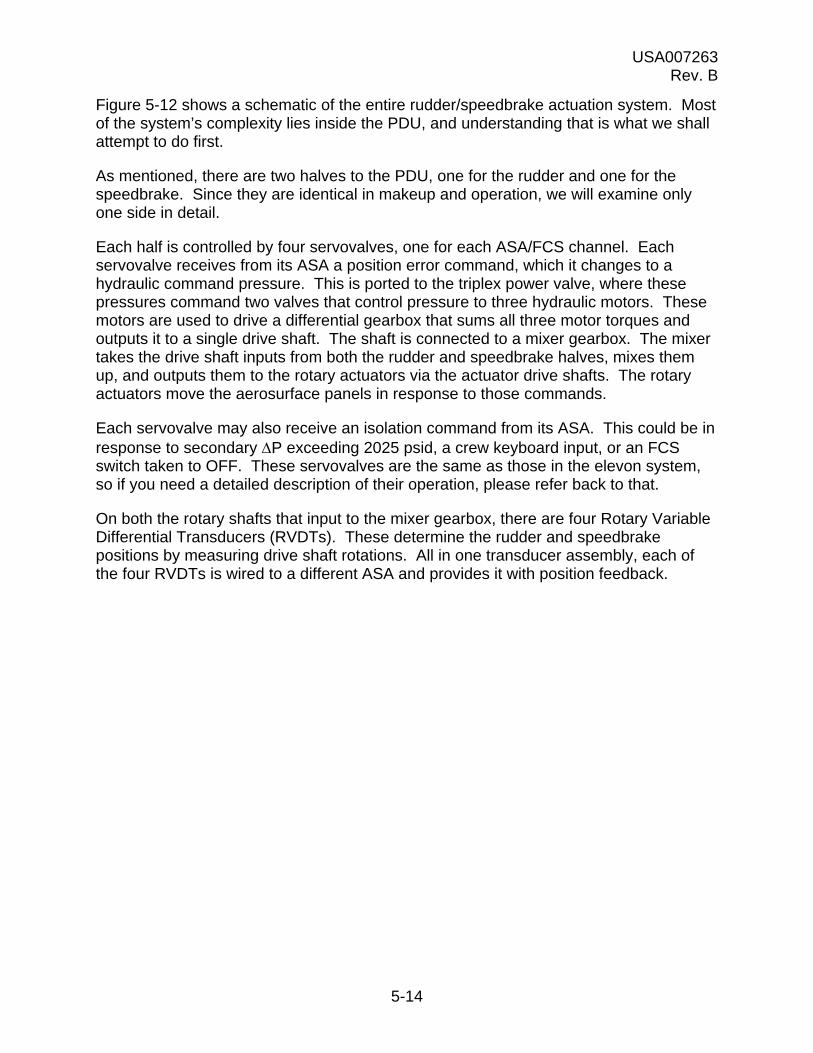
Figure 5-12 shows a schematic of the entire rudder/speedbrake actuation system. Most of the system’s complexity lies inside the PDU, and understanding that is what we shall attempt to do first.
As mentioned, there are two halves to the PDU, one for the rudder and one for the speedbrake. Since they are identical in makeup and operation, we will examine only one side in detail.
Each half is controlled by four servovalves, one for each ASA/FCS channel. Each servovalve receives from its ASA a position error command, which it changes to a hydraulic command pressure. This is ported to the triplex power valve, where these pressures command two valves that control pressure to three hydraulic motors. These motors are used to drive a differential gearbox that sums all three motor torques and outputs it to a single drive shaft. The shaft is connected to a mixer gearbox. The mixer takes the drive shaft inputs from both the rudder and speedbrake halves, mixes them up, and outputs them to the rotary actuators via the actuator drive shafts. The rotary actuators move the aerosurface panels in response to those commands.
Each servovalve may also receive an isolation command from its ASA. This could be in response to secondary P exceeding 2025 psid, a crew keyboard input, or an FCS switch taken to OFF. These servovalves are the same as those in the elevon system, so if you need a detailed description of their operation, please refer back to that.
On both the rotary shafts that input to the mixer gearbox, there are four Rotary Variable Differential Transducers (RVDTs). These determine the rudder and speedbrake positions by measuring drive shaft rotations. All in one transducer assembly, each of the four RVDTs is wired to a different ASA and provides it with position feedback.

USA007263 Rev. B
5-15
Figure 5-12. Rudder/speedbrake actuation subsystem
Isolation CMD
Command pressure
td341_035.cnv
ASA 1 Servovalve1
Secondaryforce-sumactuator(triplexpowervalve)
ASA 2
ASA 3
ASA 4
HYD motorpressureCommand
pressure
Commandpressure
Command pressure
HYD motorpressure
HYD motor
pressure
HYD motor+
brake assy
HYD motor+
brake assy
HYD motor+
brake assy
Drive
Drive
Drive
Differentialgearbox
HYD motorpressure
HYD motorpressure
HYD motorpressure
HYD motor+
brake assy
HYD motor+
brake assy
HYD motor
POS CMD
+brake assy
Drive
SEC P
Drive
Drive
Differentialgearbox
All fourASAs
POSFBK
Mixergearbox 1 2 3 4
Gearedrotary
actuators
POSFBK
Servovalve2
Servovalve3
Servovalve4
Isolation CMD
POS CMD
SEC P
Isolation CMD
POS CMD
SEC P
Isolation CMD
POS CMD
SEC P
Isolation CMD
Command pressureASA 1 Servovalve
1
Secondaryforce-sumactuator(triplexpowervalve)
ASA 2
ASA 3
ASA 4
Commandpressure
Commandpressure
Command pressurePOS CMD
SEC P
Servovalve2
Servovalve3
Servovalve4
Isolation CMD
POS CMD
SEC P
Isolation CMD
POS CMD
SEC P
Isolation CMD
POS CMD
SEC P
USA007263 Rev. B
5-16
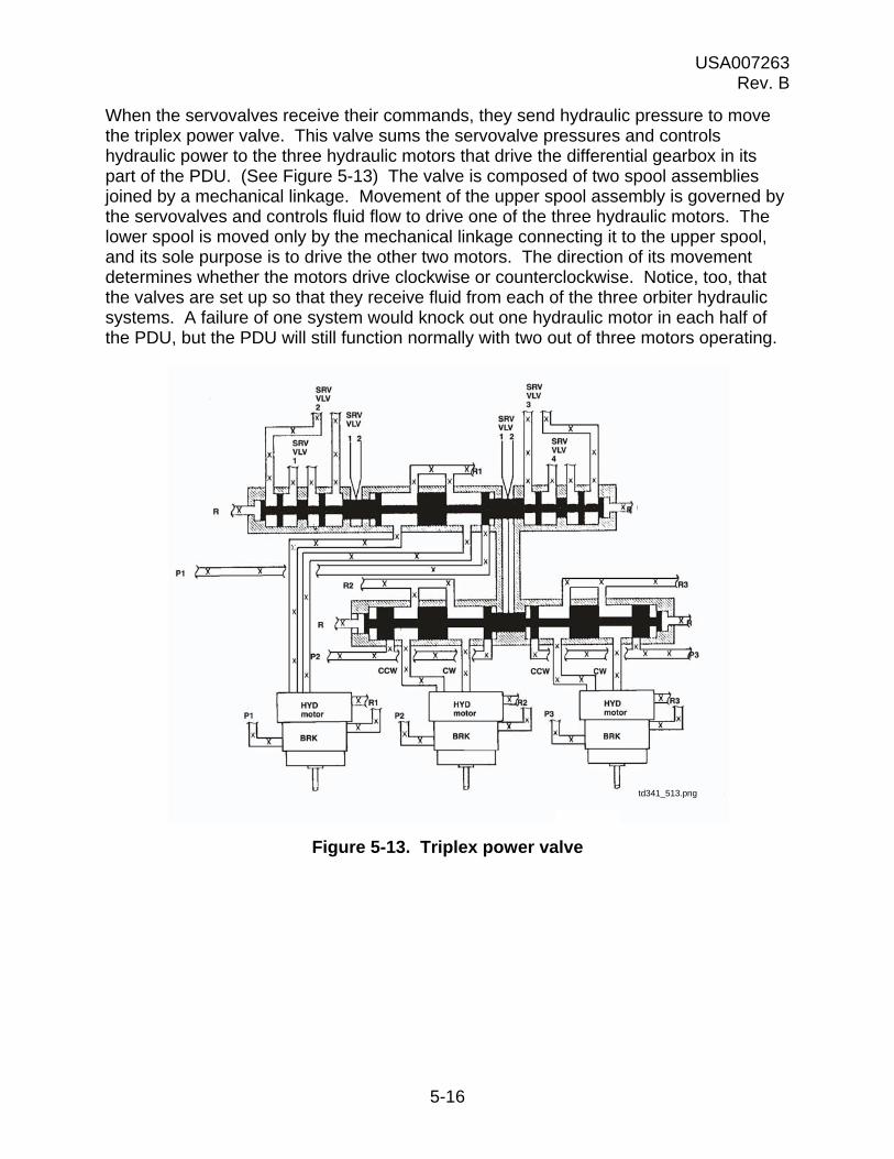
When the servovalves receive their commands, they send hydraulic pressure to move the triplex power valve. This valve sums the servovalve pressures and controls hydraulic power to the three hydraulic motors that drive the differential gearbox in its part of the PDU. (See Figure 5-13) The valve is composed of two spool assemblies joined by a mechanical linkage. Movement of the upper spool assembly is governed by the servovalves and controls fluid flow to drive one of the three hydraulic motors. The lower spool is moved only by the mechanical linkage connecting it to the upper spool, and its sole purpose is to drive the other two motors. The direction of its movement determines whether the motors drive clockwise or counterclockwise. Notice, too, that the valves are set up so that they receive fluid from each of the three orbiter hydraulic systems. A failure of one system would knock out one hydraulic motor in each half of the PDU, but the PDU will still function normally with two out of three motors operating.
Figure 5-13. Triplex power valve
td341_513.png
USA007263 Rev. B
5-17
The hydraulic motors themselves consist of a motor assembly and a brake assembly connected to a common shaft (Figure 5-14). Inside the motor assembly case are a rotating barrel, sliding pads, and a slanted, fixed ramp. The rotating barrel has, around its perimeter, cylinders containing pistons attached to the sliding pads. The tops of the cylinders jut above the top face of the rotating barrel and against the motor assembly case. Two hydraulic fluid inlets are connected to the case above the highest part of the fixed ramp but on opposing sides, and enough cylinder holes are in the rotating barrel so that a cylinder hole or parts of two are always underneath an inlet. Hydraulic fluid will flow into the cylinder hole, creating pressure on its piston. This will push the piston and its sliding pad against the sloping fixed ramp. The sliding pad will slide down the hill, and its piston will exert a push against the rotating barrel, turning it. Since the motor drive shafts are attached to the rotating barrel, they also turn. The motor drive shafts drive the gears in the differential gearbox and open or close the rudder or speedbrake, as the case may be.
Figure 5-14. Hydraulic motor/brake assembly
In the discussion above, we assumed that hydraulic fluid entered the leftmost inlet, turning the rotating barrel counterclockwise and closing the speedbrake. How is the speedbrake opened? The right inlet is pressurized, which turns the rotating barrel clockwise via the process already described. (It pushes the sliding pad down the other side of the fixed ramp.)
The bottom half of a hydraulic motor is composed of a brake assembly. The assembly consists of a disc rotor fastened to the motor drive shaft and brake shoes fastened to the motor casing. Hydraulic fluid enters through the brake assembly casing and is used

USA007263 Rev. B
5-18
to hold the discs away from the rotor. Therefore, loss of hydraulic pressure will engage the brakes and prevent the drive shaft from rotating. This was done to protect the differential gearbox (Figure 5-15). If a hydraulic failure occurs and the motor drive shaft is free to rotate, the action of the other two good motors through the gearbox will drive the defective one in reverse. It will act like a hydraulic pump and this, in turn, will transmit an opposite torque into the differential gearbox. This could break a drive shaft in the gearbox, resulting in loss of output to the aerosurface for the entire assembly.
Figure 5-15. Differential gearbox
The gearbox is designed so that a single hydraulic motor can drive the surface. The gearbox is composed of two orbital gear assemblies that are linked back to back. Torque from the center motor is transmitted to the center shaft of the first orbital assembly, the right is geared to the outer sprocket of the first orbital assembly, and the left is geared to the outer sprocket of the second orbital assembly. This allows all three motor torques to be combined during normal operation, yet still provides for operation even with multiple motor/hydraulic failures. One motor failure will not affect gearbox operation, but two motor failures will slow gearbox operation by 50 percent.
The differential gearbox outputs motor torques to a common shaft connected to the mixer gearbox. This shaft provides the rudder or speedbrake input to the mixer, as applicable. It is also the shaft on which the position transducer assemblies (one for the rudder and one for the speedbrake) are mounted to provide rudder/speedbrake position feedbacks.
The mixer gearbox receives the torques from the speedbrake and rudder differential gearboxes, mixes them together, and outputs the results to two drive shafts connected
CW
CCW
To mixer gearbox
First orbitalgear assemblies
td341_515.cnv
CCWCCW
From hydraulic motors
Second orbitalgear assemblies

USA007263 Rev. B
5-19
to the geared rotary actuators. The gearbox contains two orbital gear assemblies, each driven by one of the two rudder/speedbrake differential gearboxes.
The assemblies are geared so that speedbrake torque is input to the center of the gear assemblies. This causes the output shafts to rotate in opposite directions. The rudder torque is transmitted to the outer sprocket of the gear assemblies and causes the output shafts to rotate in the same direction. Figure 5-16 illustrates how this works.
Figure 5-16. Mixer gearbox
From thespeedbrakedifferentialgearbox
From therudder
differentialgearbox
To the geared rotaryactuators
td341_516..cnv

USA007263 Rev. B
5-20
Commands from the mixer gearbox have to be transmitted to the rotary actuators that move the rudder/speedbrake. The mixer gearbox outputs torque to two columns of aluminum drive shafts. Each column contains four drive shafts. These are used to connect the four rotary actuators together and to the PDU (Figure 5-17). This system enables one PDU to drive all the actuators and keep them synchronized.
Figure 5-17. Drive shaft connections
Rotary actuators
Drive shafts
Powerdrive unit
All four actuators are linked togetherby a series of drive shafts.
Drive shafts are madeof aluminum.
Drive shaftlinkage points
td341_517.cnv
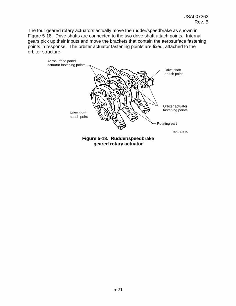
USA007263 Rev. B
5-21
The four geared rotary actuators actually move the rudder/speedbrake as shown in Figure 5-18. Drive shafts are connected to the two drive shaft attach points. Internal gears pick up their inputs and move the brackets that contain the aerosurface fastening points in response. The orbiter actuator fastening points are fixed, attached to the orbiter structure.
Figure 5-18. Rudder/speedbrake geared rotary actuator
Drive shaftattach point
Orbiter actuatorfastening points
Rotating part
Aerosurface panelactuator fastening points
Drive shaftattach point
td341_518.cnv
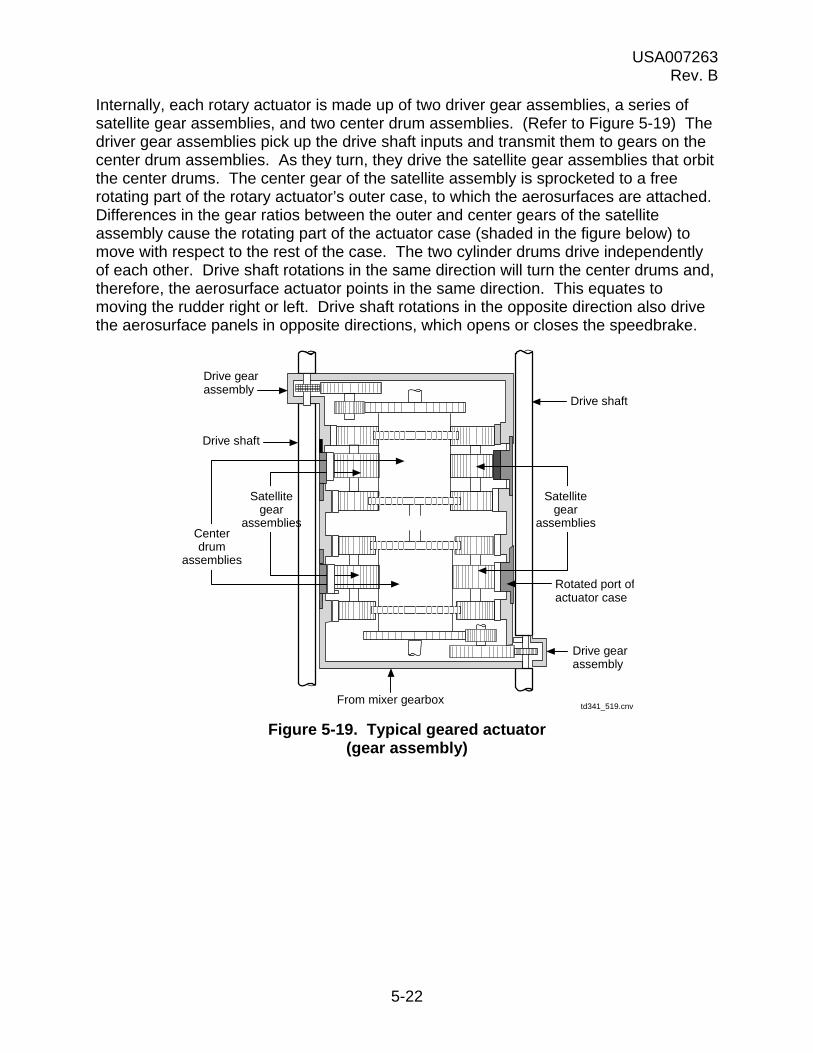
USA007263 Rev. B
5-22
Internally, each rotary actuator is made up of two driver gear assemblies, a series of satellite gear assemblies, and two center drum assemblies. (Refer to Figure 5-19) The driver gear assemblies pick up the drive shaft inputs and transmit them to gears on the center drum assemblies. As they turn, they drive the satellite gear assemblies that orbit the center drums. The center gear of the satellite assembly is sprocketed to a free rotating part of the rotary actuator’s outer case, to which the aerosurfaces are attached. Differences in the gear ratios between the outer and center gears of the satellite assembly cause the rotating part of the actuator case (shaded in the figure below) to move with respect to the rest of the case. The two cylinder drums drive independently of each other. Drive shaft rotations in the same direction will turn the center drums and, therefore, the aerosurface actuator points in the same direction. This equates to moving the rudder right or left. Drive shaft rotations in the opposite direction also drive the aerosurface panels in opposite directions, which opens or closes the speedbrake.
Figure 5-19. Typical geared actuator (gear assembly)
td341_519.cnv
Centerdrum
assemblies
Satellitegear
assemblies
Satellitegear
assemblies
Drive gearassembly
Drive shaft
Drive shaft
Drive gearassembly
Rotated port ofactuator case
From mixer gearbox
USA007263 Rev. B
5-23
Figure 5-20 shows how drive shaft, actuator, and aerosurface movements correlate.
The top part of the figure shows how the rudder works. Here, the drive shafts are rotating in the same direction. The center drum assemblies also drive in the same direction (right or left) and ultimately move the rudder/speedbrake panels right or left symmetrically.
The bottom half of the figure illustrates actuator/speedbrake motion. The drive shafts turn opposite from each other, driving the actuator lock points in different directions. This splits apart (or pulls together) the aerosurface panels operating the speedbrake.

USA007263 Rev. B
5-24
Figure 5-20. Rudder and speedbrake movements

USA007263 Rev. B
5-25
5.3 BODY FLAP
Located at the very end of the orbiter fuselage is a large aerosurface known as the BF (refer to Figure 5-21). The BF performs the following functions:
a. Provides thermal protection for the main engines during entry
b. Keeps the elevons in the proper position for thermal protection at high Mach and provides lateral controllability from Mach 5 to 2 and reduced hinge moment from Mach 2.0 to 0.9
Figure 5-21. Body flap function
5.3.1 For Entry
a. The downward deflection of the BF provides nose down pitch and vice versa.
b. The BF is used for elevon load relief and trim control and serves as a main engine heat shield.
5.3.2 For Ascent
The BF is fixed in the trail position at 0.
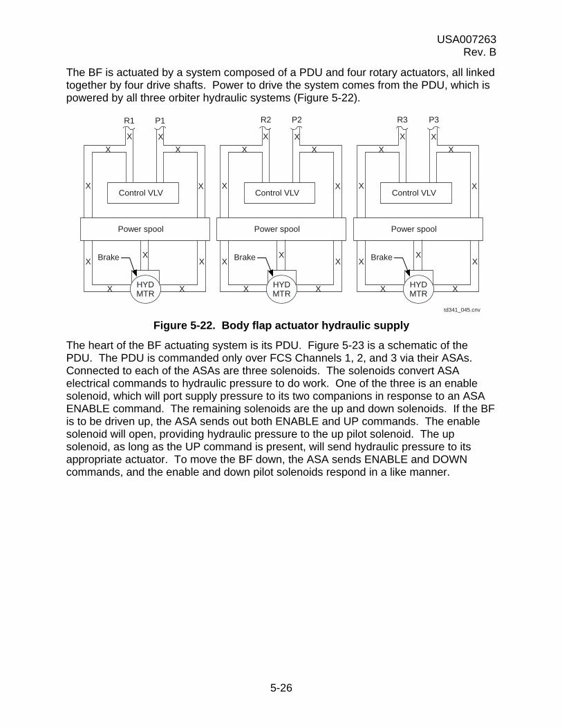
USA007263 Rev. B
5-26
The BF is actuated by a system composed of a PDU and four rotary actuators, all linked together by four drive shafts. Power to drive the system comes from the PDU, which is powered by all three orbiter hydraulic systems (Figure 5-22).
Figure 5-22. Body flap actuator hydraulic supply
The heart of the BF actuating system is its PDU. Figure 5-23 is a schematic of the PDU. The PDU is commanded only over FCS Channels 1, 2, and 3 via their ASAs. Connected to each of the ASAs are three solenoids. The solenoids convert ASA electrical commands to hydraulic pressure to do work. One of the three is an enable solenoid, which will port supply pressure to its two companions in response to an ASA ENABLE command. The remaining solenoids are the up and down solenoids. If the BF is to be driven up, the ASA sends out both ENABLE and UP commands. The enable solenoid will open, providing hydraulic pressure to the up pilot solenoid. The up solenoid, as long as the UP command is present, will send hydraulic pressure to its appropriate actuator. To move the BF down, the ASA sends ENABLE and DOWN commands, and the enable and down pilot solenoids respond in a like manner.
P1
Brake
td341_045.cnv
R1
Control VLV
Power spool
HYDMTR
X X
X X
X X
X X
X X
R2 P2 R3 P3
X Brake
Control VLV
Power spool
HYDMTR
X X
X X
X X
X X
X XX Brake
Control VLV
Power spool
HYDMTR
X X
X X
X X
X X
X XX

USA007263 Rev. B
5-27
Figure 5-23. Body flap PDU
Hydraulic pressure from the up or down solenoids travels to the appropriate actuator, which controls hydraulic flow to drive its respective hydraulic motor/brake assembly. The three actuators are mechanically linked so that any one actuator can move the other two. Each of the three actuators is powered by a different orbiter hydraulic system.
In turn, the hydraulic motor/brake assemblies drive gearshafts connected to a differential gearbox. The differential gearbox uses those torques to turn driveshafts to the BF rotary actuators. In response, the rotary actuators move the BF up and down.
BF position feedback comes from a transducer assembly of four RVDTs on the differential gearbox output. One RVDT is assigned to each FCS channel/ASA.
Drive(up/down)
td341_046.cnv
ASA 1
Up CMD Pilotsolenoid
Up POS
EnableCMD
System enablesolenoid
DownCMD Down POS
ASA 2
Up CMD
EnableCMD
DownCMD
ASA 3
Up CMD
EnableCMD
DownCMD
Actuator1
P1
Brake press
HYD motorpress
P2
P3
Hydraulicmotor/brake
assembly3
Differentialgearbox
Drive shaft
POSFBK
ASA 1ASA 2
ASA 3ASA 4
Drive(up/down)
Brake press
HYD motorpress
Brake press
HYD motorpress
Hydraulicmotor/brake
assembly2
Hydraulicmotor/brake
assembly1
Drive(up/down)
Actuator2
Actuator3
Pilotsolenoid
Pilotsolenoid
System enablesolenoid
Pilotsolenoid
Pilotsolenoid
System enablesolenoid
Pilotsolenoid
Up POS
Down POS
Up POS
Down POS
USA007263 Rev. B
5-28
Figure 5-24 shows a schematic of one set of PDU solenoids and the hydraulic actuator they control. You can follow the hydraulic paths from each solenoid to see how they work. Ultimately, you will end at the power spool assembly, the heart of the actuator. The power spool is moved by hydraulic flow from the solenoids, which will port hydraulic pressure to first release the brakes and then to drive the motor. (On the figure, the lines used are marked “Brake pressure,” “Up drive,” and “Down drive.”)
Note that the end of the power spool is attached to the mechanical linkage from the other two actuators. These linkages act to average out the commands received by all three power spools and ensure that all three motors drive in the same direction. They also serve to drive power spools to the proper positions. For instance, in a case where commands have been lost (ASA commfault or failure) but hydraulic pressure is still good, they provide for normal BF operation. The caveat in this situation is that the loss of two hydraulic systems reduces the BF deflection rate by 50 percent.
Note, too, that the actuator incorporates a recirculation valve that will open if the hydraulic pressure drops below 800 psig and allow hydraulic pressure to bypass the actuator. (If the hydraulic pressure is this low, it is more badly needed somewhere else.)
When the actuator decides flow direction, it ports hydraulic pressure to drive its hydraulic motor. To do this, it supplies pressure to the brakes to release them and to the motor’s rotating barrel to turn it. The fluid that enters the barrel pushes down on a piston and its sliding pad. This causes the sliding pad to slide down the fixed ramp.
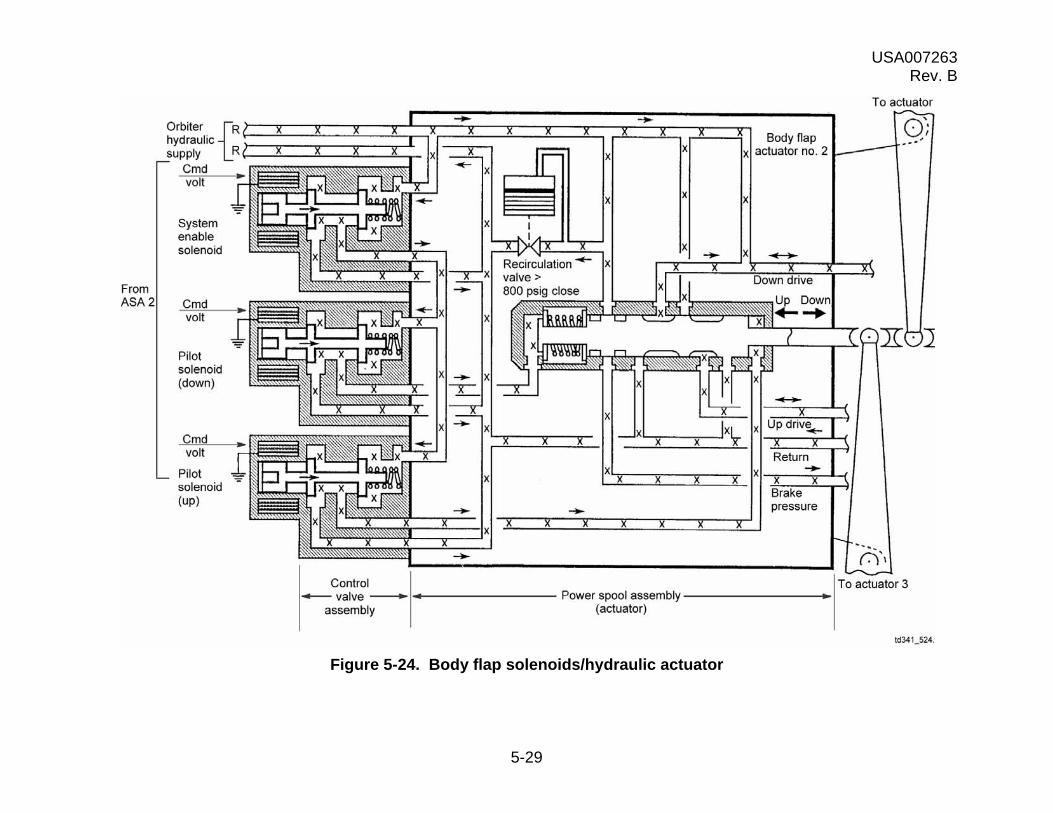
USA007263 Rev. B
5-29
Figure 5-24. Body flap solenoids/hydraulic actuator

USA007263 Rev. B
5-30
The sliding pad puts a torque on the rotating barrel. There are enough of these piston/pad assemblies so that, as one rotates from under the fluid inlet, another takes its place. Therefore, as long as fluid pressure is supplied to an inlet, a motor will try to turn. Because the motor drive shaft is attached to the rotating barrel, it turns. Figure 5-25 shows a motor and how it works. If pressure to the brake assembly falls to less than 1000 psi, the brakes will engage. This prevents the motor from being driven by the differential gearbox and causing undesirable loads.
The three motors via their drive shafts input three torques to the differential gearbox. The gearbox, through two orbital gear assemblies, slims the torques and outputs them to a common drive shaft. This drive shaft uses a bevel gear assembly to turn the drive shafts powering the rotary actuators. In response, the rotary actuators move the BF up and down.
Figure 5-26 shows the setup. (A detailed explanation of the gearbox orbital gears and their operation may be found in the rudder/speedbrake section.) Note that BF position feedback is picked off the gearbox output shaft. The transducer assembly that does this is composed of four rotary variable differential transducers, each of which is wired to a different ASA. All four FCS channels receive position feedbacks.
However, the BF is commanded only over FCS Channels 1, 2, and 3. In this respect, it is different from many other aerosurfaces. (Refer to Figure 4-6). Channel 4 is used only to provide position feedback to the Primary Avionics Software System (PASS).
Figure 5-25. Hydraulic motor/brake assembly
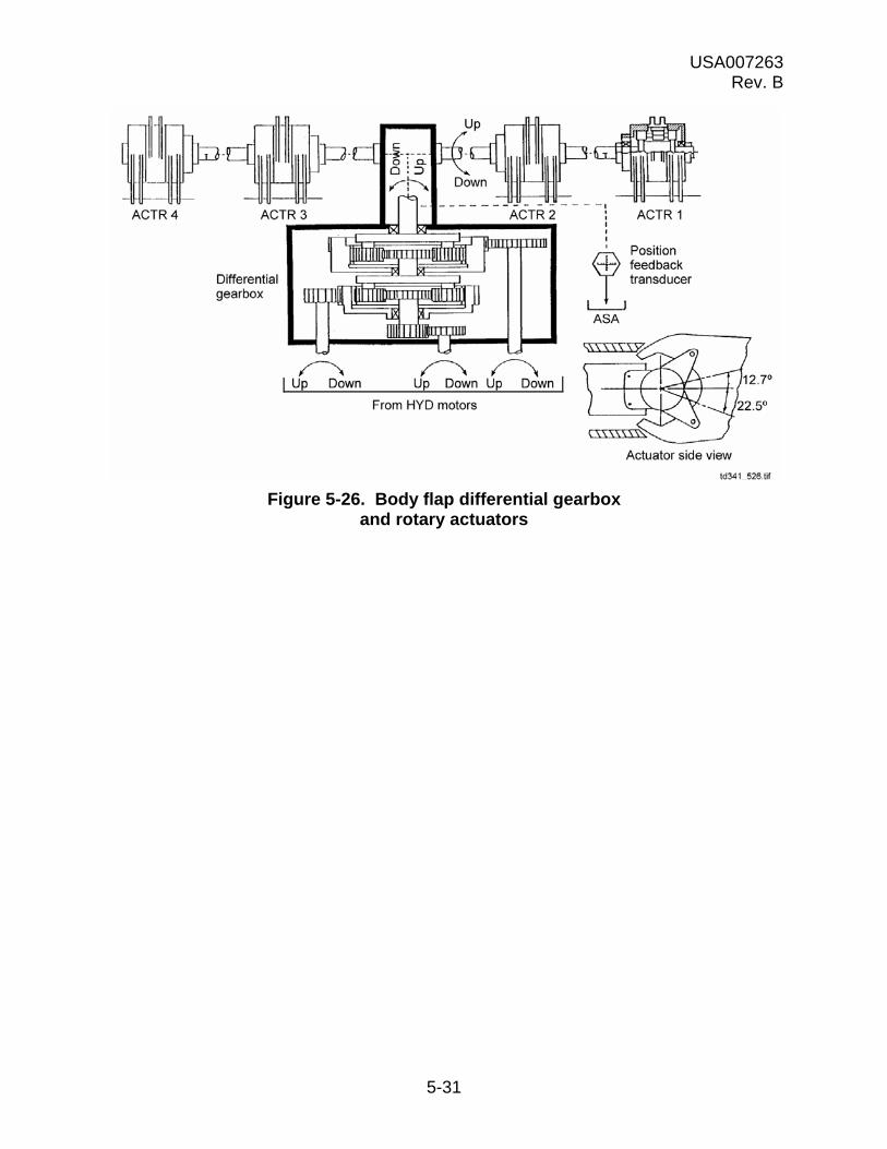
USA007263 Rev. B
5-31
Figure 5-26. Body flap differential gearbox and rotary actuators

USA007263 Rev. B
5-32
5.4 QUESTIONS
1. Describe elevon action
(a) During ascent
(b) During entry
2. How is hydraulic power to the elevons controlled? What happens if the primary hydraulic system fails?
3. What does a servovalve do? To where does its pressure go?
4. What controls pressure to the actuator’s primary ram?
5. Name the mechanical components of the rudder/speedbrake system.
6. How many servovalves are in the rudder/speedbrake PDU?
7. What purpose does the differential gearbox serve? The mixer gearbox?
8. Describe the triplex power valve. What does it do?
9. How does a hydraulic motor work?
10. Will a PDU operate if two of its three motors fail?
11. Drive shafts rotating in the same direction move the __________. Drive shafts rotating in opposite directions move the __________.
12. What purpose does the BF serve during entry?
13. Describe the mechanical components of the BF system.
14. How many commands are required to move the BF?
15. Are the BF PDU actuators mechanically linked?

USA007263 Rev. B
6-1
6.0 SOFTWARE
6.1 AEROSURFACE COMMAND SOFTWARE FLOW
Flight control software within the GPCs generates the aerosurface position commands that are forwarded to the aeroactuator Subsystem Operating Program (SOP). The SOP adds I-loaded biases and scale factors to convert the commands to volts dc that the ASA can use (referred to as command compensation). These compensated commands are sent to the ASA where they become position error commands that move the aerosurfaces. (Refer to Figure 6-1)
Figure 6-1. Aerosurface command software data flow
For the elevons, speedbrake, and rudder in OPS 1, 3, and 6, the command compensation occurs at 25 Hz. Processing for the BF is done at 6.25 Hz.
Override commands are generated when a crewmember takes the FCS switches to ORIDE. These commands are also processed by the aeroactuator SOP and routed to the ASAs, where they reset any bypassed secondary actuators and override the fault detection logic. Reset commands are the equivalent of override commands and are set by crew keyboard entries via the FCS C/O DED display in OPS 8 or SPEC 53 in OPS 1, 3, or 6.
Bypass commands are generated by taking an FCS channel switch to OFF or by keyboard commands. SPEC 53 and the FCS C/O DED display both provide this latter capability. All bypass commands travel directly to the ASA. Taking an FCS channel switch to OFF will bypass all the secondary actuators on that channel. Keyboard entries will allow selection of individual actuators for bypassing.
6.2 ELEVON FEEDBACKS
This data is used within the ASA and is passed on to the GPC. Once inside GPC software, it goes to RM. RM consists of two parts, Fault Detection, Isolation, and Reconfiguration (FDIR) and the Selection Filter (SF). FDIR compares the redundant data and checks it for out-of-tolerance conditions. If none are found, the data is forwarded to the SF. If something is wrong, the bad data is identified, thrown out, and the remaining good data is forwarded to the SF. The SF takes the multiple data inputs and reduces them to a single parameter. (For instance, it receives three position feedbacks for each elevon, which it reduces through a Midvalue Select (MVS) scheme
Position CMDS
FCS channeloverride
Actuator bypass CMDS
Flight control
Crewinterface
AeroactuatorSOP
Scaling
Actuatoroverrideprocessing
td341_050.cnv
ASAs (4) Aerosurfaces

USA007263 Rev. B
6-2
to one elevon position.) The selected data is then forwarded to the SOPs, which convert them to engineering units for use in flight control software, crew displays, and C&W (Figure 6-2).
Elevon primary Ps are used to calculate their hinge moments. Hinge moments that are too high are an indication that the elevon(s) is aerodynamically loaded to its maximum and is at its maximum effectiveness. When this occurs, the crew is alerted by C&W lights and messages that are discussed later.
Elevon Position Feedbacks (PFBs) are used for flight control purposes. When they reach their limits, the crew is alerted by C&W.
It is the SOPs that put this data in a form the GPCs can use. Elevon position feedback SOP converts the elevon PFBs from volts to degrees and finds the elevator position by averaging the four results ((LIB + LOB + RIB + ROB) 4).
Now that we have an overview, we will look at a few things in more detail, starting with position feedback RM.
As already stated, RM consists of FDIR and SF. The first thing to understand is that FDIR operates per elevon. (This means that FDIR on the Left Inboard (LIB) and the Left Outboard (LOB) may be doing different things.) For each elevon, FDIR compares the PFBs for Channels 1, 2, and 3 against each other, as follows:
|PFB1 - PFB2|< LIMIT |PBF2 - PFB3|< LIMIT |PFB1 - PFB3|< LIMIT
If any two results exceed the limit three consecutive times, the common parameter is declared failed. Notice that the Channel 4 feedback is not included in the scheme. This value is normally kept on standby. However, when a Channel 1, 2, or 3 parameter is failed, FDIR substitutes the Channel 4 value in its place. FDIR then quits. This means that if any of the remaining parameters go outside limits, no failure identification will be performed on them and they could influence the value the SF comes up with. FDIR needs all four PFBs to operate. Should FDIR lose a channel’s PFBs due to commfault or crew deselection, FDIR will quit. Should the crew reselect the channel’s PFBs or the commfault clear, FDIR will upmode to normal operation. (See Figure 6-3)
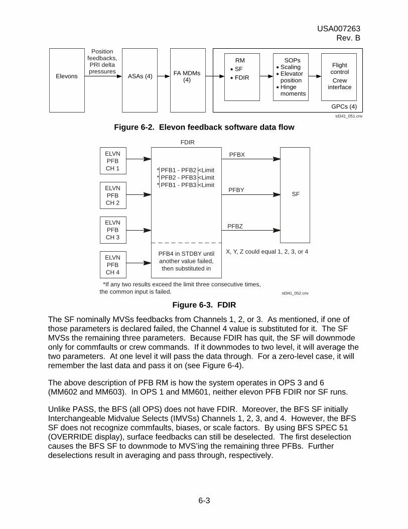
USA007263 Rev. B
6-3
Figure 6-2. Elevon feedback software data flow
Figure 6-3. FDIR
The SF nominally MVSs feedbacks from Channels 1, 2, or 3. As mentioned, if one of those parameters is declared failed, the Channel 4 value is substituted for it. The SF MVSs the remaining three parameters. Because FDIR has quit, the SF will downmode only for commfaults or crew commands. If it downmodes to two level, it will average the two parameters. At one level it will pass the data through. For a zero-level case, it will remember the last data and pass it on (see Figure 6-4).
The above description of PFB RM is how the system operates in OPS 3 and 6 (MM602 and MM603). In OPS 1 and MM601, neither elevon PFB FDIR nor SF runs.
Unlike PASS, the BFS (all OPS) does not have FDIR. Moreover, the BFS SF initially Interchangeable Midvalue Selects (IMVSs) Channels 1, 2, 3, and 4. However, the BFS SF does not recognize commfaults, biases, or scale factors. By using BFS SPEC 51 (OVERRIDE display), surface feedbacks can still be deselected. The first deselection causes the BFS SF to downmode to MVS’ing the remaining three PFBs. Further deselections result in averaging and pass through, respectively.
Positionfeedbacks,PRI deltapressures
td341_051.cnv
Elevons ASAs (4) FA MDMs(4)
RM
SF
FDIR
SOPsScalingElevator
positionHinge
moments
Flightcontrol
Crewinterface
GPCs (4)
FDIR
* PFB1 - PFB2 <Limit* PFB2 - PFB3 <Limit* PFB1 - PFB3 <Limit
PFB4 in STDBY untilanother value failed,then substituted in
SF
ELVNPFBCH 1
PFBX
X, Y, Z could equal 1, 2, 3, or 4
*If any two results exceed the limit three consecutive times,the common input is failed.
PFBY
PFBZ
td341_052.cnv
ELVNPFBCH 2
ELVNPFBCH 3
ELVNPFBCH 4

USA007263 Rev. B
6-4
The elevon PFBs are also used to generate messages (FCS Saturation Position (FCS SAT POS)), which occur when the elevons are deflected to the hardstops. These messages can be generated in OPS 3 and 6 (PASS and BFS).
Figure 6-4. PASS selection filter
Elevon primary P is used to modify elevon position during first-stage ascent load relief and to generate (FCS Saturation Moment)(FCS SAT MOM)) messages. During load relief (MM102), the elevons are moved to correspond to an I-loaded schedule. If the load on them becomes too high, the elevons will be moved to bring their hinge moments back within limits (unload them). In OPS 3 and MM602 and MM603, primary P is used exclusively to calculate elevon hinge moments. If they exceed I-loaded limits, an FCS SAT MOM message is displayed. This tells the crew that elevon loading has become critical, and they may be reaching a point where flight control is marginal.
Both the FCS SAT POS and FCS SAT MOM messages are accompanied by an FCS saturation light and a backup C&W light on the C&W panel on F7. There will also be a C&W tone and a master alarm light. Figure 6-5 shows the indications that will be displayed.
SF
X, Y, Z could equal 1, 2, 3, or 4
FDIR
Commfaults
PFBX
Selected PFB
3 levelmidvalue selects
2 levelaverages
1 levelpassthrough
0 levellast data
*Downmode/upmode
PFBY
PFBZ
Crew commands
*Downmode means the SF drops to the next lower level.Upmode means it jumps up to the next higher level.
td341_053.cnv
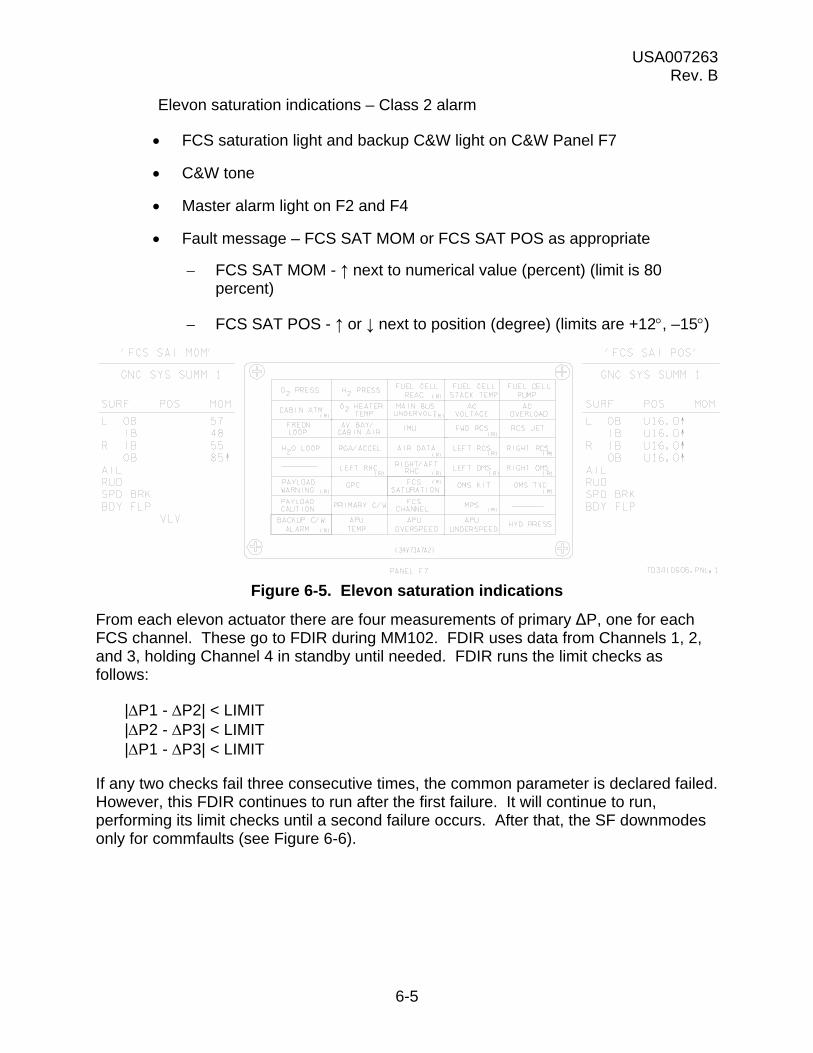
USA007263 Rev. B
6-5
Elevon saturation indications – Class 2 alarm
FCS saturation light and backup C&W light on C&W Panel F7
C&W tone
Master alarm light on F2 and F4
Fault message – FCS SAT MOM or FCS SAT POS as appropriate
– FCS SAT MOM - ↑ next to numerical value (percent) (limit is 80 percent)
– FCS SAT POS - ↑ or ↓ next to position (degree) (limits are +12, –15)
Figure 6-5. Elevon saturation indications
From each elevon actuator there are four measurements of primary ΔP, one for each FCS channel. These go to FDIR during MM102. FDIR uses data from Channels 1, 2, and 3, holding Channel 4 in standby until needed. FDIR runs the limit checks as follows:
|P1 - P2| < LIMIT |P2 - P3| < LIMIT |P1 - P3| < LIMIT
If any two checks fail three consecutive times, the common parameter is declared failed. However, this FDIR continues to run after the first failure. It will continue to run, performing its limit checks until a second failure occurs. After that, the SF downmodes only for commfaults (see Figure 6-6).

USA007263 Rev. B
6-6
Figure 6-6. Elevon primary ΔP FDIR and SF
Therefore, when only two parameters are available, whether through commfaults or failures, the SF alone processes the data. It will MVS, average, or pass through parameters, depending upon how many it has. If it loses the last one, it will put out the last valid signal it has.
The above is how the elevon primary P FIDR and SF operate in MM102. In OPS 3 and 6, however, the primary P FIDR does not operate. The SF alone MVSs Channels 1, 2, and 3 primary Ps; the Channel 4 primary P is ignored. The SF downloads only for commfaults (refer to Figure 6-7).
When the SFs have completed their functions, the data goes to the elevon primary P SOP, where it is converted to engineering units. From there, the data is used based on the current OPS mode. In MM102, the data goes to the ascent Digital Autopilot (DAP). In OPS 3 and 6, the data goes to GN&C annunciation for monitoring and display on GN&C SYS SUMM 1.
In OPS 3 and 6, the elevon position feedback SFs feed their data to the elevon PFBs SOP. The SOP converts the data from volts to degrees and averages the elevon inputs to compute an elevon position. The SOP outputs the elevator positions to the DAP, to GN&C annunciation for monitoring and display on GNC SYS SUMM 1, and to the SPI, telemetry, and hydraulic thermal conditioning.
FDIR
td341 055.cnv
3 levelmidvalue selects
2 levelaverage
* 1 levelpassthrough
* 0 levellast data
*Downmode/upmode
PX
PY
PZ
*Downmodes/upmodes for commfault only.
Commfaults
ELVNP
CH1
|P1 - P2|<Limit|P2 - P3|<Limit|P1 - P3|<Limit
P4 held in standby
ELVNP
CH2
ELVNP
CH3
ELVNP
CH4
P1
P2
P3
P4
SF
Selected P
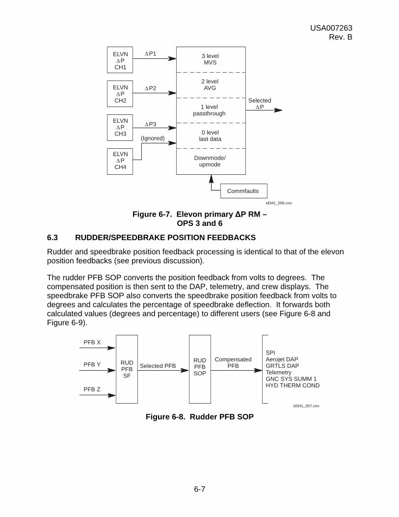
USA007263 Rev. B
6-7
Figure 6-7. Elevon primary ΔP RM – OPS 3 and 6
6.3 RUDDER/SPEEDBRAKE POSITION FEEDBACKS
Rudder and speedbrake position feedback processing is identical to that of the elevon position feedbacks (see previous discussion).
The rudder PFB SOP converts the position feedback from volts to degrees. The compensated position is then sent to the DAP, telemetry, and crew displays. The speedbrake PFB SOP also converts the speedbrake position feedback from volts to degrees and calculates the percentage of speedbrake deflection. It forwards both calculated values (degrees and percentage) to different users (see Figure 6-8 and Figure 6-9).
Figure 6-8. Rudder PFB SOP
td341_056.cnv
3 levelMVS
2 levelAVG
1 levelpassthrough
0 levellast data
Downmode/upmode
Commfaults
ELVNP
CH1
ELVNP
CH2
ELVNP
CH3
ELVNP
CH4
P1
P2
P3
SelectedP
(Ignored)
PFB X
CompensatedPFBSelected PFBRUD
PFBSF
RUDPFBSOP
SPIAerojet DAPGRTLS DAPTelemetryGNC SYS SUMM 1HYD THERM COND
PFB Y
PFB Z
td341_057.cnv
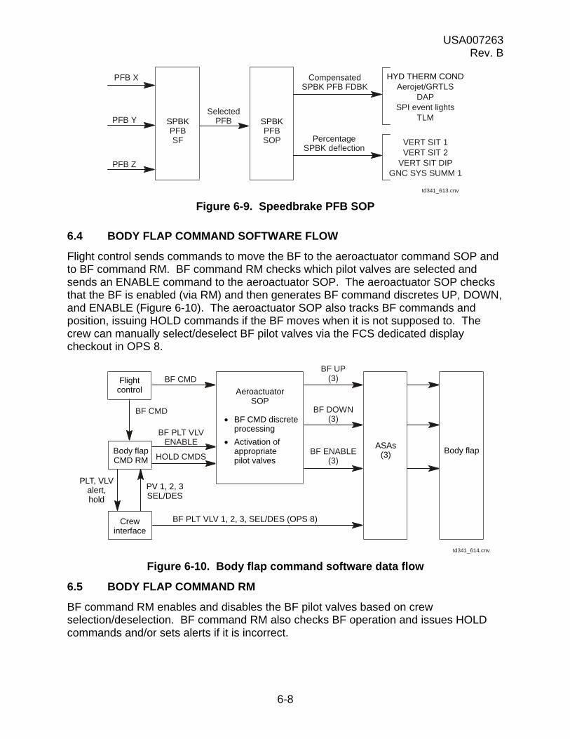
USA007263 Rev. B
6-8
Figure 6-9. Speedbrake PFB SOP
6.4 BODY FLAP COMMAND SOFTWARE FLOW
Flight control sends commands to move the BF to the aeroactuator command SOP and to BF command RM. BF command RM checks which pilot valves are selected and sends an ENABLE command to the aeroactuator SOP. The aeroactuator SOP checks that the BF is enabled (via RM) and then generates BF command discretes UP, DOWN, and ENABLE (Figure 6-10). The aeroactuator SOP also tracks BF commands and position, issuing HOLD commands if the BF moves when it is not supposed to. The crew can manually select/deselect BF pilot valves via the FCS dedicated display checkout in OPS 8.
Figure 6-10. Body flap command software data flow
6.5 BODY FLAP COMMAND RM
BF command RM enables and disables the BF pilot valves based on crew selection/deselection. BF command RM also checks BF operation and issues HOLD commands and/or sets alerts if it is incorrect.
PFB X CompensatedSPBK PFB FDBK
SelectedPFB
PercentageSPBK deflection
PFB Y
PFB Z
VERT SIT 1VERT SIT 2
VERT SIT DIPGNC SYS SUMM 1
td341_613.cnv
SPBKPFBSOP
HYD THERM CONDAerojet/GRTLS
DAPSPI event lights
TLMSPBKPFBSF
BF UP(3)
BF CMD
td341_614.cnv
Body flapCMD RM
PLT, VLValert,hold
PV 1, 2, 3SEL/DES
AeroactuatorSOP
BF CMD discreteprocessing
Activation ofappropriatepilot valves
BF DOWN(3)
BF ENABLE(3)
ASAs(3) Body flap
BF PLT VLVENABLE
HOLD CMDS
BF PLT VLV 1, 2, 3, SEL/DES (OPS 8)
BF CMDFlightcontrol
Crewinterface
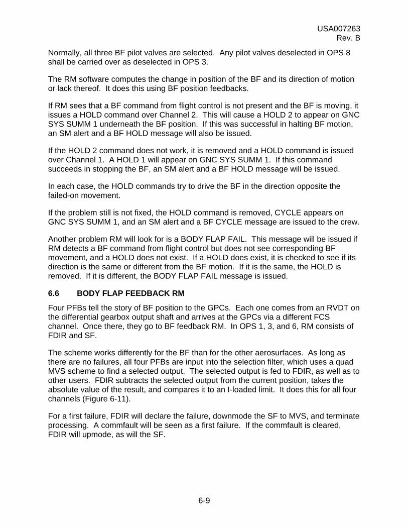
USA007263 Rev. B
6-9
Normally, all three BF pilot valves are selected. Any pilot valves deselected in OPS 8 shall be carried over as deselected in OPS 3.
The RM software computes the change in position of the BF and its direction of motion or lack thereof. It does this using BF position feedbacks.
If RM sees that a BF command from flight control is not present and the BF is moving, it issues a HOLD command over Channel 2. This will cause a HOLD 2 to appear on GNC SYS SUMM 1 underneath the BF position. If this was successful in halting BF motion, an SM alert and a BF HOLD message will also be issued.
If the HOLD 2 command does not work, it is removed and a HOLD command is issued over Channel 1. A HOLD 1 will appear on GNC SYS SUMM 1. If this command succeeds in stopping the BF, an SM alert and a BF HOLD message will be issued.
In each case, the HOLD commands try to drive the BF in the direction opposite the failed-on movement.
If the problem still is not fixed, the HOLD command is removed, CYCLE appears on GNC SYS SUMM 1, and an SM alert and a BF CYCLE message are issued to the crew.
Another problem RM will look for is a BODY FLAP FAIL. This message will be issued if RM detects a BF command from flight control but does not see corresponding BF movement, and a HOLD does not exist. If a HOLD does exist, it is checked to see if its direction is the same or different from the BF motion. If it is the same, the HOLD is removed. If it is different, the BODY FLAP FAIL message is issued.
6.6 BODY FLAP FEEDBACK RM
Four PFBs tell the story of BF position to the GPCs. Each one comes from an RVDT on the differential gearbox output shaft and arrives at the GPCs via a different FCS channel. Once there, they go to BF feedback RM. In OPS 1, 3, and 6, RM consists of FDIR and SF.
The scheme works differently for the BF than for the other aerosurfaces. As long as there are no failures, all four PFBs are input into the selection filter, which uses a quad MVS scheme to find a selected output. The selected output is fed to FDIR, as well as to other users. FDIR subtracts the selected output from the current position, takes the absolute value of the result, and compares it to an I-loaded limit. It does this for all four channels (Figure 6-11).
For a first failure, FDIR will declare the failure, downmode the SF to MVS, and terminate processing. A commfault will be seen as a first failure. If the commfault is cleared, FDIR will upmode, as will the SF.
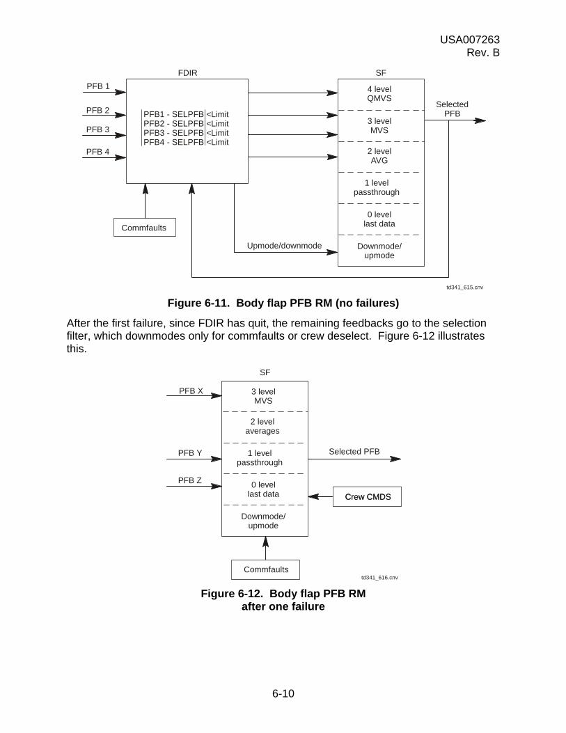
USA007263 Rev. B
6-10
Figure 6-11. Body flap PFB RM (no failures)
After the first failure, since FDIR has quit, the remaining feedbacks go to the selection filter, which downmodes only for commfaults or crew deselect. Figure 6-12 illustrates this.
Figure 6-12. Body flap PFB RM after one failure
PFB 1
SFFDIR
Upmode/downmode
PFB 2
PFB 3
PFB 4
SelectedPFBPFB1 - SELPFB <Limit
PFB2 - SELPFB <LimitPFB3 - SELPFB <LimitPFB4 - SELPFB <Limit
4 levelQMVS
3 levelMVS
2 levelAVG
1 levelpassthrough
0 levellast data
Downmode/upmode
Commfaults
td341_615.cnv
PFB X
PFB Y
PFB Z
Selected PFB
Crew CMDS
td341_616.cnv
SF
3 levelMVS
2 levelaverages
1 levelpassthrough
0 levellast data
Downmode/upmode
Crew CMDS
Commfaults
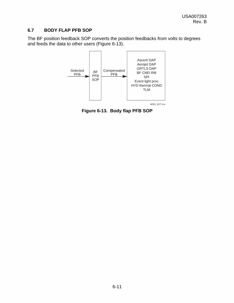
USA007263 Rev. B
6-11
6.7 BODY FLAP PFB SOP
The BF position feedback SOP converts the position feedbacks from volts to degrees and feeds the data to other users (Figure 6-13).
Figure 6-13. Body flap PFB SOP
CompensatedPFB
Ascent DAPAerojet DAPGRTLS DAPBF CMD RM
SPIEvent light proc
HYD thermal CONDTLM
SelectedPFB
BFPFBSOP
td341_617.cnv
USA007263 Rev. B
6-12
6.8 QUESTIONS
1. What does the aeroactuator subsystems operating program do?
2. What two parts compose elevon feedback RM?
3. How does elevon position feedback FDIR work?
4. What downmodes the SF (OPS 3)?
5. When does elevon PFB FDIR run?
6. How does elevon PFB RM work in BFS?
7. How does elevon P RM work?
8. How many position feedbacks come back from the rudder/speedbrake?
9. When does rudder/speedbrake FDIR run? The SF?
10. What will happen if the BF UP command on FCS CH 1 fails on?
11. What causes a BF fail?
12. Describe how BF PFB RM works.

USA007263 Rev. B
7-1
7.0 CREW DISPLAYS
7.1 SURFACE POSITION INDICATOR
The SPI provides a gauge-type display for the crew to check aerosurface position. Viewable on any MEDS MFD, the gauge is driven in all OPS 3, OPS 8, MM602, and MM603.
Figures 7-1 through 7-6 and the text on the next few pages explain the SPI in more detail.
Figure 7-1. Surface position indicator

USA007263 Rev. B
7-2
a. The position of each elevon is indicated in degrees deflection by the triangular pointer.
b. The scale is calibrated from 0 to 35 up and 0 to 20 down. Up deflection is indicated as negative, and down deflection is positive.
c. The LOB elevon is read on the leftmost scale, LIB is read on the center left scale, Right Inboard (RIB) is read on the center right scale, and the Right Outboard (ROB) is read on the rightmost scale.
Figure 7-2. Elevon position – SPI
-30
TE UP
ELEVONSDEG
-20
-10
0
+10
+20
TE DN
td341_064.cnv
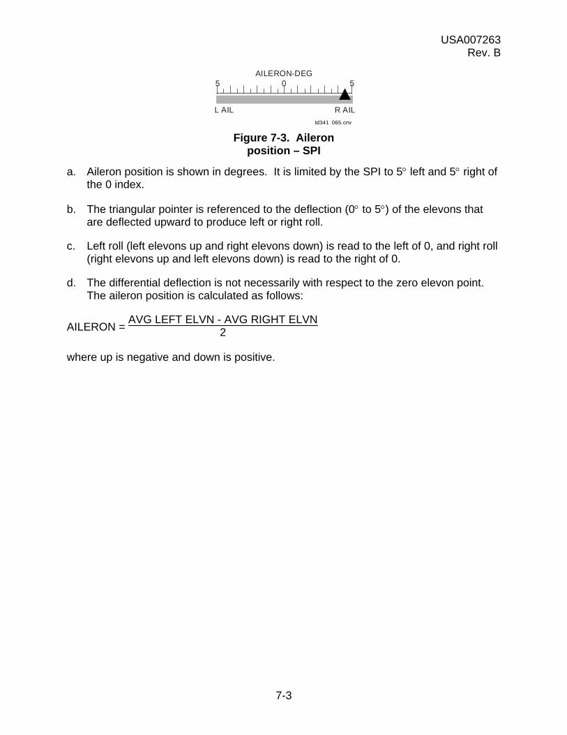
USA007263 Rev. B
7-3
Figure 7-3. Aileron position – SPI
a. Aileron position is shown in degrees. It is limited by the SPI to 5 left and 5 right of the 0 index.
b. The triangular pointer is referenced to the deflection (0 to 5) of the elevons that are deflected upward to produce left or right roll.
c. Left roll (left elevons up and right elevons down) is read to the left of 0, and right roll (right elevons up and left elevons down) is read to the right of 0.
d. The differential deflection is not necessarily with respect to the zero elevon point. The aileron position is calculated as follows:
AILERON = AVG LEFT ELVN - AVG RIGHT ELVN
2
where up is negative and down is positive.
td341_065.cnv
5 0 5AILERON-DEG
L AIL R AIL
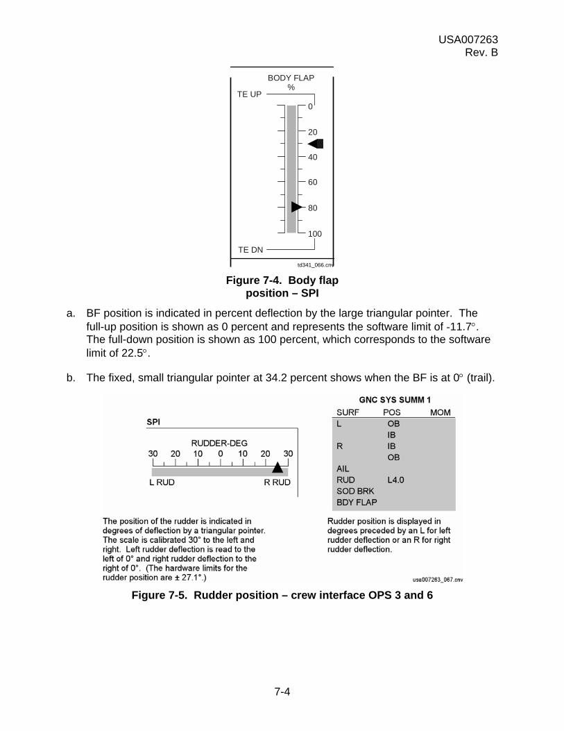
USA007263 Rev. B
7-4
Figure 7-4. Body flap position – SPI
a. BF position is indicated in percent deflection by the large triangular pointer. The full-up position is shown as 0 percent and represents the software limit of -11.7. The full-down position is shown as 100 percent, which corresponds to the software limit of 22.5.
b. The fixed, small triangular pointer at 34.2 percent shows when the BF is at 0 (trail).
Figure 7-5. Rudder position – crew interface OPS 3 and 6
TE UP
BODY FLAP%
TE DN
0
20
40
60
100
80
td341_066.cnv

USA007263 Rev. B
7-5
Figure 7-6. Speedbrake position – SPI OPS 3, 6
7.2 RCS ACTIVITY LIGHTS
During entry, the RCS activity lights perform an important FCS function. In MM304, 305, 602, and 603, when the pitch jets have been turned off and dynamic pressure exceeds 50 psf, both RCS pitch lights will illuminate when elevon rate saturation occurs. This is at a maximum rate of 20 deg/sec. Either left or right elevons moving at this rate will turn on the lights (Figure 7-7).
Figure 7-7. RCS activity lights
7.3 CRT DISPLAYS
7.3.1 GNC SYS SUMM 1
Available to the crew in all OPS in PASS is GNC SYS SUMM 1 (Figure 7-8). In the center of the display are aerosurface position and moment readouts. In the middle of the right-hand side, the crew can see FCS channel status. The position and moment readout portion of the display is supported during OPS 3 and MM602 and MM603. If the elevons hit the hardstops, a “” or an “” will be displayed next to the numerical position (depending upon whether it hit the hardstops going up or going down), and an FCS SAT POS message will appear. If the elevon hinge moments get too high, an “” will appear next to the moment readout (percent), and an FCS SAT MOM message will appear.
0 20 40 60 80 100XXX
XXX
SPEEDBRAKE %ACTUAL
COMMAND
td341 068.cnv
Speedbrake deflection in percentis indicated by the upper pointer.The auto guidance-speedbrakecommand via flight control in percentis indicated by the lower pointer.Both scales are the same and arecalibrated from 0 to 100 percent.0 indicates that the speedbrakes arefully closed. 100 percent correspondsto speedbrakes fully open (98.6°included angle).

USA007263 Rev. B
7-6
BF problems will be annunciated under the BF position readout. HOLD 1, HOLD 2, or CYCLE messages will reveal what is going on.
FCS channel status is supported in OPS 1, 3, and 6. A port popping on an ATVC in OPS 1 and 6 or an ASA in OPS 1, 3, and 6 will put a “” under the applicable FCS channel number. The “” will remain as long as a port is bypassed.
Figure 7-8. GNC SYS SUMM 1 display
7.3.2 SPEC 53
SPEC 53 gives the most detailed insight into the status of the aerosurface system. It is available in both OPS 1 and OPS 3 (PASS) (Figure 7-9).
Figure 7-9. CONTROLS display
The upper left-hand portion of the display allows you to perform a secondary actuator check in OPS 3. Item numbers allow individual selection of the channels to be checked
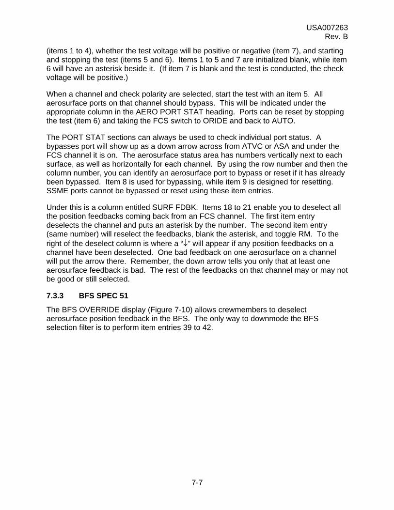
USA007263 Rev. B
7-7
(items 1 to 4), whether the test voltage will be positive or negative (item 7), and starting and stopping the test (items 5 and 6). Items 1 to 5 and 7 are initialized blank, while item 6 will have an asterisk beside it. (If item 7 is blank and the test is conducted, the check voltage will be positive.)
When a channel and check polarity are selected, start the test with an item 5. All aerosurface ports on that channel should bypass. This will be indicated under the appropriate column in the AERO PORT STAT heading. Ports can be reset by stopping the test (item 6) and taking the FCS switch to ORIDE and back to AUTO.
The PORT STAT sections can always be used to check individual port status. A bypasses port will show up as a down arrow across from ATVC or ASA and under the FCS channel it is on. The aerosurface status area has numbers vertically next to each surface, as well as horizontally for each channel. By using the row number and then the column number, you can identify an aerosurface port to bypass or reset if it has already been bypassed. Item 8 is used for bypassing, while item 9 is designed for resetting. SSME ports cannot be bypassed or reset using these item entries.
Under this is a column entitled SURF FDBK. Items 18 to 21 enable you to deselect all the position feedbacks coming back from an FCS channel. The first item entry deselects the channel and puts an asterisk by the number. The second item entry (same number) will reselect the feedbacks, blank the asterisk, and toggle RM. To the right of the deselect column is where a “” will appear if any position feedbacks on a channel have been deselected. One bad feedback on one aerosurface on a channel will put the arrow there. Remember, the down arrow tells you only that at least one aerosurface feedback is bad. The rest of the feedbacks on that channel may or may not be good or still selected.
7.3.3 BFS SPEC 51
The BFS OVERRIDE display (Figure 7-10) allows crewmembers to deselect aerosurface position feedback in the BFS. The only way to downmode the BFS selection filter is to perform item entries 39 to 42.
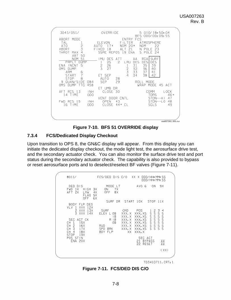
USA007263 Rev. B
7-8
Figure 7-10. BFS 51 OVERRIDE display
7.3.4 FCS/Dedicated Display Checkout
Upon transition to OPS 8, the GN&C display will appear. From this display you can initiate the dedicated display checkout, the mode light test, the aerosurface drive test, and the secondary actuator check. You can also monitor the surface drive test and port status during the secondary actuator check. The capability is also provided to bypass or reset aerosurface ports and to deselect/reselect BF valves (Figure 7-11).
Figure 7-11. FCS/DED DIS C/O
usa007263_005.cvx
USA007263 Rev. B
7-9
Items 1 and 2 determine which crew station, forward or aft, is selected for test. Only one can be selected at a time. Items 3 to 6 control which tests are being executed or terminates them.
Items 7 and 8 control the mode light test. This test turns on the FCS mode lights with an item 7. This checks the lights only. The test is stopped with an item 8.
The surface drive test is commanded on with an item 10. This test checks the GPC’s ability to drive the aerosurfaces by driving them from stop to stop, which also warms up the hydraulic fluid. The test will continue to run until an item 11 is executed.
Under these two item numbers are two columns showing the commands being issued and the current surface positions. Immediately to the right of the surface position readout is a column where a “” will appear if the difference between a command and a position exceeds a limit during the test. An AERO DRIVE fault message will also be generated.
Centered on the left side of the display are item numbers 12, 13, and 14 that allow you to deselect/reselect which valves are commanding the BF motion. A status column also shows whether the BF valves are enabled or inhibited.
Below this is the secondary actuator check (SEC ACT CK). This section allows you to check the isolation valves on each channel for each aerosurface. It does this by applying a 6 bias to the selected channel. If the test is being conducted with a positive stimulus, the bias will be +6 (elevons). If there is a negative stimulus, the bias will be -6. This bias will cause a force fight between its channel and the other three, driving its secondary P above 2025 psi and bypassing the port. To conduct the test, select positive or negative stimulus by toggling item 20 and then select the channel to be tested (items 15 to 18). All the ports on that channel should bypass. This will be indicated by down arrows under the channel number. Stop the test with an item 19 and reset the ports by taking the FCS switch to ORIDE and then back to AUTO.
The last part of the display (SEC ACT) is in the lower right-hand corner. It allows bypassing or resetting of aerosurface ports. By performing an item 21 + “desired actuator port,” the appropriate port bypasses. An item 22 + “desired actuator port” will reset bypassed ports. To determine the correct number for the desired actuator port, consult the DPS Dictionary.
USA007263 Rev. B
7-10
7.4 QUESTIONS
1. What is the SPI and when does it work?
2. How can you tell if the BF is in trail?
3. When will both RCS pitch activity lights illuminate?
4. Where would you look to see which aerosurfaces generated an FCS SAT message?
5. During an entry, you get an FCS CH 3 message and a down arrow on GNC SYS SUMM 1. Where would you look to see what has happened?
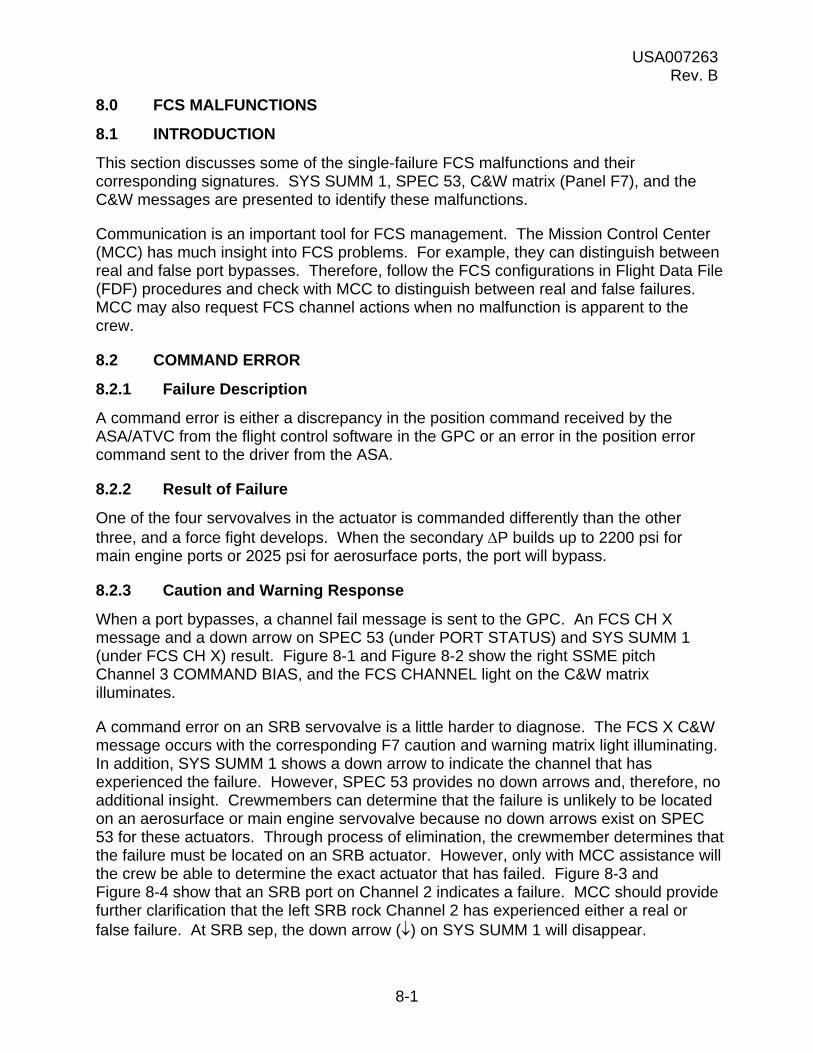
USA007263 Rev. B
8-1
8.0 FCS MALFUNCTIONS
8.1 INTRODUCTION
This section discusses some of the single-failure FCS malfunctions and their corresponding signatures. SYS SUMM 1, SPEC 53, C&W matrix (Panel F7), and the C&W messages are presented to identify these malfunctions.
Communication is an important tool for FCS management. The Mission Control Center (MCC) has much insight into FCS problems. For example, they can distinguish between real and false port bypasses. Therefore, follow the FCS configurations in Flight Data File (FDF) procedures and check with MCC to distinguish between real and false failures. MCC may also request FCS channel actions when no malfunction is apparent to the crew.
8.2 COMMAND ERROR
8.2.1 Failure Description
A command error is either a discrepancy in the position command received by the ASA/ATVC from the flight control software in the GPC or an error in the position error command sent to the driver from the ASA.
8.2.2 Result of Failure
One of the four servovalves in the actuator is commanded differently than the other three, and a force fight develops. When the secondary P builds up to 2200 psi for main engine ports or 2025 psi for aerosurface ports, the port will bypass.
8.2.3 Caution and Warning Response
When a port bypasses, a channel fail message is sent to the GPC. An FCS CH X message and a down arrow on SPEC 53 (under PORT STATUS) and SYS SUMM 1 (under FCS CH X) result. Figure 8-1 and Figure 8-2 show the right SSME pitch Channel 3 COMMAND BIAS, and the FCS CHANNEL light on the C&W matrix illuminates.
A command error on an SRB servovalve is a little harder to diagnose. The FCS X C&W message occurs with the corresponding F7 caution and warning matrix light illuminating. In addition, SYS SUMM 1 shows a down arrow to indicate the channel that has experienced the failure. However, SPEC 53 provides no down arrows and, therefore, no additional insight. Crewmembers can determine that the failure is unlikely to be located on an aerosurface or main engine servovalve because no down arrows exist on SPEC 53 for these actuators. Through process of elimination, the crewmember determines that the failure must be located on an SRB actuator. However, only with MCC assistance will the crew be able to determine the exact actuator that has failed. Figure 8-3 and Figure 8-4 show that an SRB port on Channel 2 indicates a failure. MCC should provide further clarification that the left SRB rock Channel 2 has experienced either a real or false failure. At SRB sep, the down arrow () on SYS SUMM 1 will disappear.

USA007263 Rev. B
8-2
Figure 8-1. GNC SYS SUMM 1 display
Figure 8-2. CONTROLS display
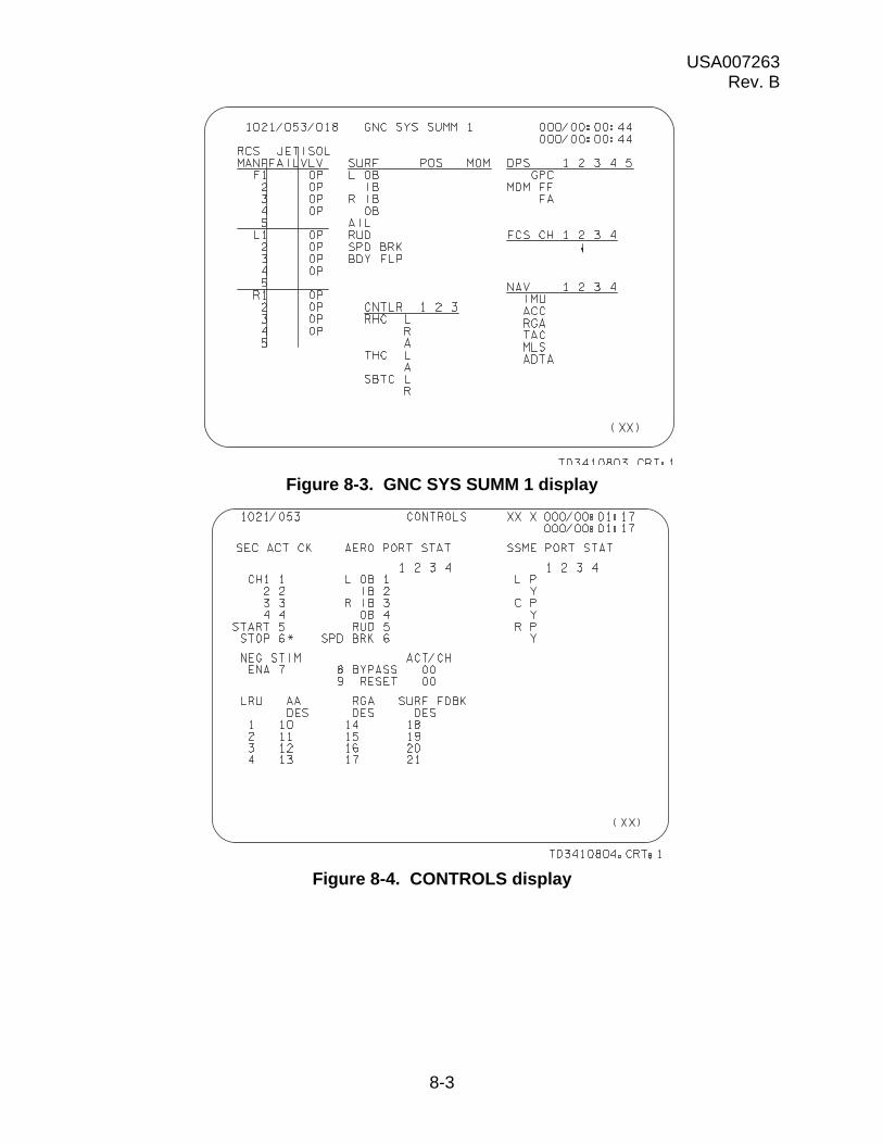
USA007263 Rev. B
8-3
Figure 8-3. GNC SYS SUMM 1 display
Figure 8-4. CONTROLS display
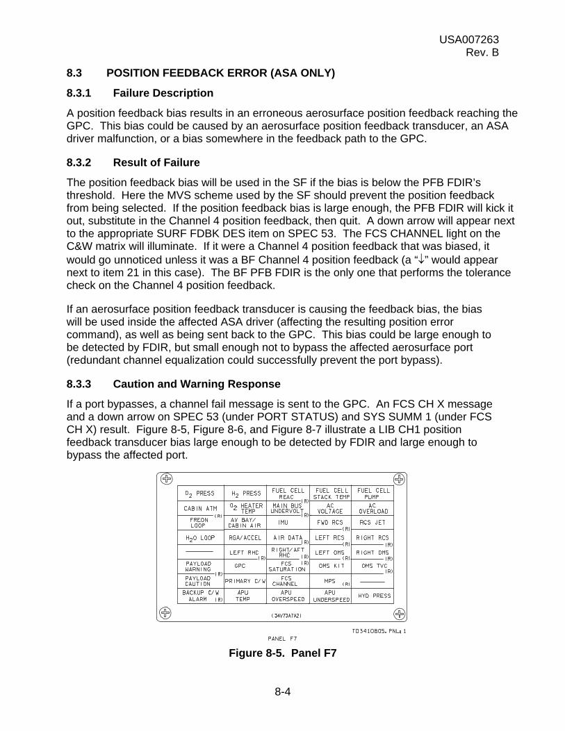
USA007263 Rev. B
8-4
8.3 POSITION FEEDBACK ERROR (ASA ONLY)
8.3.1 Failure Description
A position feedback bias results in an erroneous aerosurface position feedback reaching the GPC. This bias could be caused by an aerosurface position feedback transducer, an ASA driver malfunction, or a bias somewhere in the feedback path to the GPC.
8.3.2 Result of Failure
The position feedback bias will be used in the SF if the bias is below the PFB FDIR’s threshold. Here the MVS scheme used by the SF should prevent the position feedback from being selected. If the position feedback bias is large enough, the PFB FDIR will kick it out, substitute in the Channel 4 position feedback, then quit. A down arrow will appear next to the appropriate SURF FDBK DES item on SPEC 53. The FCS CHANNEL light on the C&W matrix will illuminate. If it were a Channel 4 position feedback that was biased, it would go unnoticed unless it was a BF Channel 4 position feedback (a “” would appear next to item 21 in this case). The BF PFB FDIR is the only one that performs the tolerance check on the Channel 4 position feedback.
If an aerosurface position feedback transducer is causing the feedback bias, the bias will be used inside the affected ASA driver (affecting the resulting position error command), as well as being sent back to the GPC. This bias could be large enough to be detected by FDIR, but small enough not to bypass the affected aerosurface port (redundant channel equalization could successfully prevent the port bypass).
8.3.3 Caution and Warning Response
If a port bypasses, a channel fail message is sent to the GPC. An FCS CH X message and a down arrow on SPEC 53 (under PORT STATUS) and SYS SUMM 1 (under FCS CH X) result. Figure 8-5, Figure 8-6, and Figure 8-7 illustrate a LIB CH1 position feedback transducer bias large enough to be detected by FDIR and large enough to bypass the affected port.
Figure 8-5. Panel F7

USA007263 Rev. B
8-5
Figure 8-6. GNC SYS SUMM 1 display
Figure 8-7. CONTROLS display
8.4 MDM/GPC FAILURES
8.4.1 Failure Description
Detailed below is what will happen to the ASA/ATVC commands and the ASA position feedback if a DPS failure occurs.
a. If the GPC fails to halt or quit, the ASA/ATVC commands will be latched, eventually causing a force fight, and all the ports on that ASA will bypass.
b. The ASA position feedbacks will be commfaulted (FDIR/SF downmodes).
USA007263 Rev. B
8-6
c. If the MDM power fails, the ASA/ATVC commands will fail to zero voltage values.
d. FCS channel is lost. The ASA position feedbacks will be commfaulted (FDIR/SF downmodes).
e. If the MDM is commfaulted, the ASA/ATVC commands will be latched, possibly failed to erroneous values.
f. If an MDM fails at the GPC, its FCS channels can be regained through a restring or BFS engage. The ASA position feedbacks will be commfaulted (FDIR/SF downmodes).
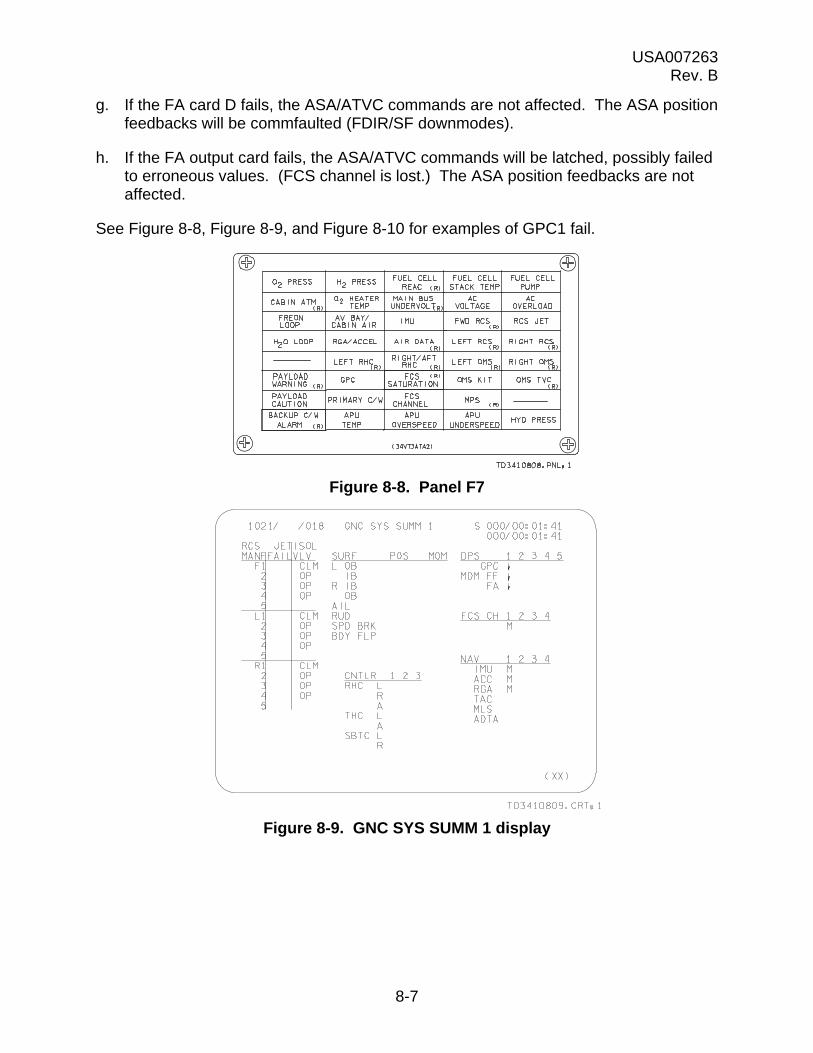
USA007263 Rev. B
8-7
g. If the FA card D fails, the ASA/ATVC commands are not affected. The ASA position feedbacks will be commfaulted (FDIR/SF downmodes).
h. If the FA output card fails, the ASA/ATVC commands will be latched, possibly failed to erroneous values. (FCS channel is lost.) The ASA position feedbacks are not affected.
See Figure 8-8, Figure 8-9, and Figure 8-10 for examples of GPC1 fail.
Figure 8-8. Panel F7
Figure 8-9. GNC SYS SUMM 1 display

USA007263 Rev. B
8-8
Figure 8-10. CONTROLS display
8.5 ASA/ATVC INTERNAL POWER FAILURE
8.5.1 Failure Description
If an ASA or ATVC internal power loss occurs, an isolation command is sent out, and all the ports on that channel bypass. This prohibits further commands from reaching each actuator through that channel. The PFBs on that channel fail to a zero voltage value.
8.5.2 Result of Failure
All the actuators will have both port bypasses and bad PFBs on this channel.
8.5.3 Caution and Warning Response
A fail flag is sent to the GPC, resulting in an FCS CH X message. Down arrows appear on SPEC 53 along all the actuators on this channel (under PORT STATUS). One down arrow appears on SYS SUMM 1 (Figure 8-11). Figure 8-12 shows the SPEC 53 signature of an ASA internal power failure, while Figure 8-13 shows an ATVC internal power failure.

USA007263 Rev. B
8-9
Figure 8-11. GNC SYS SUMM 1 display
Figure 8-12. CONTROLS display (ASA 1 failed)
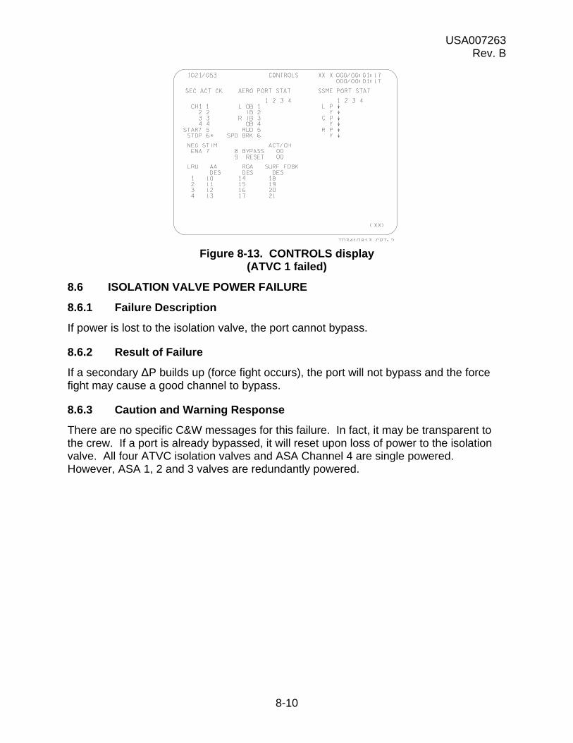
USA007263 Rev. B
8-10
Figure 8-13. CONTROLS display (ATVC 1 failed)
8.6 ISOLATION VALVE POWER FAILURE
8.6.1 Failure Description
If power is lost to the isolation valve, the port cannot bypass.
8.6.2 Result of Failure
If a secondary ΔP builds up (force fight occurs), the port will not bypass and the force fight may cause a good channel to bypass.
8.6.3 Caution and Warning Response
There are no specific C&W messages for this failure. In fact, it may be transparent to the crew. If a port is already bypassed, it will reset upon loss of power to the isolation valve. All four ATVC isolation valves and ASA Channel 4 are single powered. However, ASA 1, 2 and 3 valves are redundantly powered.
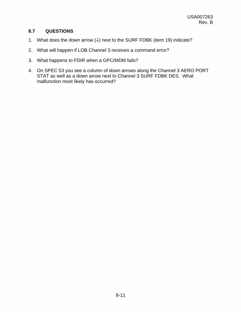
USA007263 Rev. B
8-11
8.7 QUESTIONS
1. What does the down arrow () next to the SURF FDBK (item 19) indicate?
2. What will happen if LOB Channel 3 receives a command error?
3. What happens to FDIR when a GPC/MDM fails?
4. On SPEC 53 you see a column of down arrows along the Channel 3 AERO PORT STAT as well as a down arrow next to Channel 3 SURF FDBK DES. What malfunction most likely has occurred?
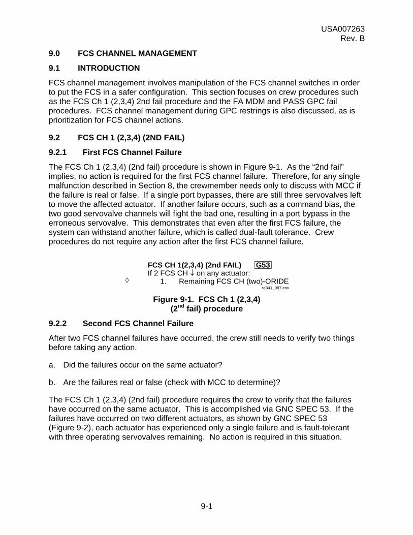
USA007263 Rev. B
9-1
9.0 FCS CHANNEL MANAGEMENT
9.1 INTRODUCTION
FCS channel management involves manipulation of the FCS channel switches in order to put the FCS in a safer configuration. This section focuses on crew procedures such as the FCS Ch 1 (2,3,4) 2nd fail procedure and the FA MDM and PASS GPC fail procedures. FCS channel management during GPC restrings is also discussed, as is prioritization for FCS channel actions.
9.2 FCS CH 1 (2,3,4) (2ND FAIL)
9.2.1 First FCS Channel Failure
The FCS Ch 1 (2,3,4) (2nd fail) procedure is shown in Figure 9-1. As the “2nd fail” implies, no action is required for the first FCS channel failure. Therefore, for any single malfunction described in Section 8, the crewmember needs only to discuss with MCC if the failure is real or false. If a single port bypasses, there are still three servovalves left to move the affected actuator. If another failure occurs, such as a command bias, the two good servovalve channels will fight the bad one, resulting in a port bypass in the erroneous servovalve. This demonstrates that even after the first FCS failure, the system can withstand another failure, which is called dual-fault tolerance. Crew procedures do not require any action after the first FCS channel failure.
Figure 9-1. FCS Ch 1 (2,3,4) (2nd fail) procedure
9.2.2 Second FCS Channel Failure
After two FCS channel failures have occurred, the crew still needs to verify two things before taking any action.
a. Did the failures occur on the same actuator?
b. Are the failures real or false (check with MCC to determine)?
The FCS Ch 1 (2,3,4) (2nd fail) procedure requires the crew to verify that the failures have occurred on the same actuator. This is accomplished via GNC SPEC 53. If the failures have occurred on two different actuators, as shown by GNC SPEC 53 (Figure 9-2), each actuator has experienced only a single failure and is fault-tolerant with three operating servovalves remaining. No action is required in this situation.
FCS CH 1(2,3,4) (2nd FAIL) G53If 2 FCS CH on any actuator:
1. Remaining FCS CH (two)-ORIDEtd341_087.cnv

USA007263 Rev. B
9-2
Figure 9-2. GNC SPEC 53
GNC SPEC 53 in Figure 9-3 shows two FCS channel failures on the same actuator. However, the crew should consult with MCC before taking any action. The FCS Ch 1 (2,3,4) (2nd fail) procedure has a diamond “” next to its action steps (Figure 9-1), which means the crew must check with MCC before continuing with the procedure. This step is important in that the GNC flight controllers can distinguish between real and false failures, while crewmembers do not have that capability.
Figure 9-3. GNC SPEC 53
If the two FCS channel failures are on the same actuator and MCC confirms that they are real failures, the affected actuator has only two operating servovalves. Although the system is operational in this configuration, the next failure could result in serious control problems. When there are only two servovalves operating and an error is introduced into one of them, a one-on-one force fight occurs within the secondary actuator. The secondary delta pressure will rise in both servovalves, and it is possible that the good
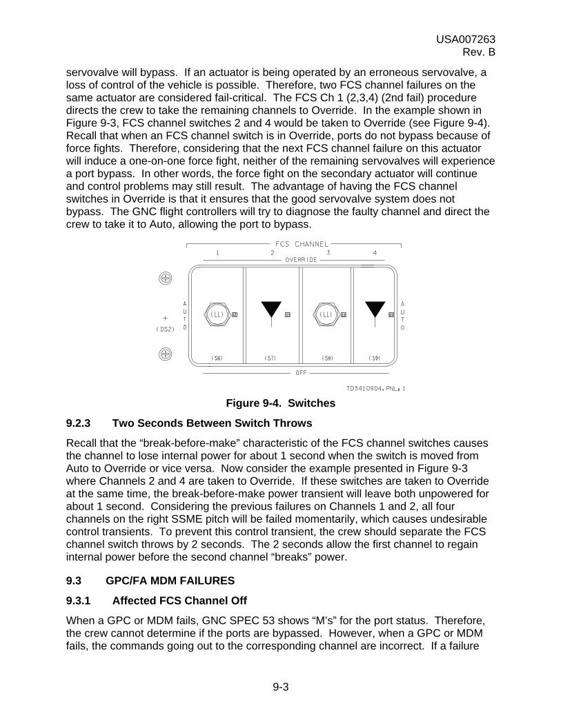
USA007263 Rev. B
9-3
servovalve will bypass. If an actuator is being operated by an erroneous servovalve, a loss of control of the vehicle is possible. Therefore, two FCS channel failures on the same actuator are considered fail-critical. The FCS Ch 1 (2,3,4) (2nd fail) procedure directs the crew to take the remaining channels to Override. In the example shown in Figure 9-3, FCS channel switches 2 and 4 would be taken to Override (see Figure 9-4). Recall that when an FCS channel switch is in Override, ports do not bypass because of force fights. Therefore, considering that the next FCS channel failure on this actuator will induce a one-on-one force fight, neither of the remaining servovalves will experience a port bypass. In other words, the force fight on the secondary actuator will continue and control problems may still result. The advantage of having the FCS channel switches in Override is that it ensures that the good servovalve system does not bypass. The GNC flight controllers will try to diagnose the faulty channel and direct the crew to take it to Auto, allowing the port to bypass.
Figure 9-4. Switches
9.2.3 Two Seconds Between Switch Throws
Recall that the “break-before-make” characteristic of the FCS channel switches causes the channel to lose internal power for about 1 second when the switch is moved from Auto to Override or vice versa. Now consider the example presented in Figure 9-3 where Channels 2 and 4 are taken to Override. If these switches are taken to Override at the same time, the break-before-make power transient will leave both unpowered for about 1 second. Considering the previous failures on Channels 1 and 2, all four channels on the right SSME pitch will be failed momentarily, which causes undesirable control transients. To prevent this control transient, the crew should separate the FCS channel switch throws by 2 seconds. The 2 seconds allow the first channel to regain internal power before the second channel “breaks” power.
9.3 GPC/FA MDM FAILURES
9.3.1 Affected FCS Channel Off
When a GPC or MDM fails, GNC SPEC 53 shows “M’s” for the port status. Therefore, the crew cannot determine if the ports are bypassed. However, when a GPC or MDM fails, the commands going out to the corresponding channel are incorrect. If a failure

USA007263 Rev. B
9-4
occurs that leaves the last command latched (stuck at its previous value), the affected port will not bypass until the commands on the other channels change appreciably. The resulting force fight will cause the port to bypass. This lag between the time of the failure and the time the port bypasses is not in itself dangerous; however, if a second failure occurs before the port bypasses, there is the potential for a two-on-two force fight. Similar to a one-on-one force fight, the two-on-two force fight could result in the good ports bypassing. To eliminate the threat of this scenario, both the PASS GPC fail procedure and the FA MDM I/O error procedure (see Figure 9-5 and Figure 9-6) require the crew to take the affected FCS channel switch to Off. This ensures that all the ports on the failed channel are bypassed. The vehicle can now withstand the next failure, which means it is single-fault tolerant.
Figure 9-5. GPC fail
Figure 9-6. MDM fail
1. GPC MODE - STBY,HALT2. Aff FCS CH - OFF3. If 2 GPC/FA/FCS CHs : Good FCS CHs - ORIDE4. G53 aff SURF FDBK - desel
5. If STRG 1(2): CDR(PLT) sws - green dot6. MULT DATA PATH LOSS
PASS GPC FAIL
td341_091.cnv
1. I/O RESETRECOV FA 2. If reqd, aff FCS CH - ORIDE, AUTO
FF If H > 200K or TACAN incorp:1,2,3 3. G50 NAV DELTA zero
4. G51 IMU - resel5. BFS I/O RESET >>
NOT FA 6. Aff FCS CH - OFFRECOV 7. If 2 GPC/FA/FCS CHs :
Good FCS CHs - ORIDE8. G53 aff SURF FDBK - desel9. MULT DATA PATH LOSS
10. Go to FA/FF MDM PORT MODE
FA/FF MDM I/O ERROR
td341_092.cnv
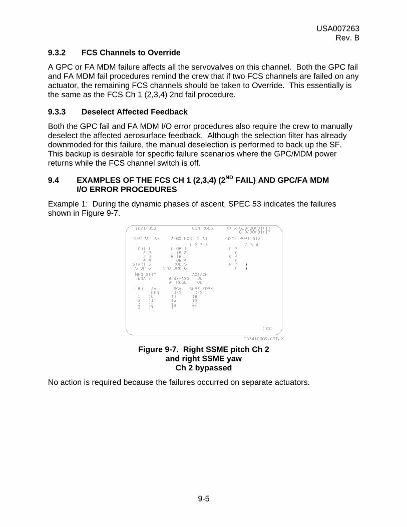
USA007263 Rev. B
9-5
9.3.2 FCS Channels to Override
A GPC or FA MDM failure affects all the servovalves on this channel. Both the GPC fail and FA MDM fail procedures remind the crew that if two FCS channels are failed on any actuator, the remaining FCS channels should be taken to Override. This essentially is the same as the FCS Ch 1 (2,3,4) 2nd fail procedure.
9.3.3 Deselect Affected Feedback
Both the GPC fail and FA MDM I/O error procedures also require the crew to manually deselect the affected aerosurface feedback. Although the selection filter has already downmoded for this failure, the manual deselection is performed to back up the SF. This backup is desirable for specific failure scenarios where the GPC/MDM power returns while the FCS channel switch is off.
9.4 EXAMPLES OF THE FCS CH 1 (2,3,4) (2ND FAIL) AND GPC/FA MDM I/O ERROR PROCEDURES
Example 1: During the dynamic phases of ascent, SPEC 53 indicates the failures shown in Figure 9-7.
Figure 9-7. Right SSME pitch Ch 2 and right SSME yaw
Ch 2 bypassed
No action is required because the failures occurred on separate actuators.

USA007263 Rev. B
9-6
Example 2: During the dynamic phases of entry, SPEC 53 indicated the failures shown in Figure 9-8.
Figure 9-8. FA 2 MDM failed and ROB Ch 4 bypassed
Following the FA MDM I/O error procedure:
1. FCS Channel 2 to Off.
2. (Check MCC to verify that the ROB Ch 4 failure is real.) FCS Channels 1 and 3 to Override.
3. Deselect FCS Ch 2 feedback (SPEC 53, item 19 EXEC).
9.5 PRIORITIZING FCS CHANNEL ACTIONS
Controlling the main engines is obviously very important for powered ascent. On entry, however, main engine control is desired only to reposition the engine bells from a thermally beneficial position to a position that will not impact the drag chute deploy. Conversely, the aerosurfaces are used only for a short time on ascent to provide load relief. On entry, the aerosurfaces are essential for maintaining control of the vehicle.
If two aerosurface ports bypass on the same actuator during ascent (after load relief), no action is required. If the remaining channels were taken to Override to protect for these aerosurface problems, subsequent ATVC problems on these channels would not be able to bypass (except ATVC internal power failures, which result in port bypasses even while the FCS channel switch is in the Override position). Protecting for ATVC failures on ascent is considered more important then ASA failures. Similarly, ASA failures are a higher priority on entry. During entry, the main engines are repositioned from a thermally desirable position to a location that is optimal for drag chute deploy. This main engine repositioning will be inhibited if the system is not fail safe. This means that when a failure exists that will cause a one-on-one or a two-on-two force fight on a

USA007263 Rev. B
9-7
main engine secondary actuator, the crew will be asked to inhibit the repositioning. However, FCS channel actions are not required for SSME repositioning because taking the switches to Override does not gain a level of fault tolerance. In other words, taking channels to Override only prevents ports from bypassing as a result of a force fight. It does not stop a force fight from occurring.
There are several benefits when FCS channel actions are avoided. First, crewmembers do not have to move switches during the dynamic timeframes of ascent and entry. This could be difficult, considering the bulky suits, as well as potential g forces. Secondly, when FCS channel switches are moved to Override, they experience the break-before-make condition. During this break power loss timeframe, there is the potential that ASA and/or ATVC system may not regain power.
To understand how prioritization affects FCS channel management, consider the following examples.
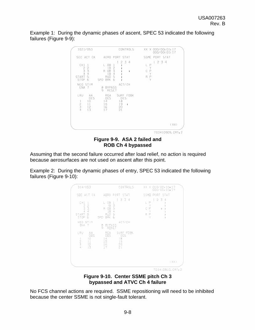
USA007263 Rev. B
9-8
Example 1: During the dynamic phases of ascent, SPEC 53 indicated the following failures (Figure 9-9):
Figure 9-9. ASA 2 failed and ROB Ch 4 bypassed
Assuming that the second failure occurred after load relief, no action is required because aerosurfaces are not used on ascent after this point.
Example 2: During the dynamic phases of entry, SPEC 53 indicated the following failures (Figure 9-10):
Figure 9-10. Center SSME pitch Ch 3 bypassed and ATVC Ch 4 failure
No FCS channel actions are required. SSME repositioning will need to be inhibited because the center SSME is not single-fault tolerant.

USA007263 Rev. B
9-9
9.5.1 Main Engine Failures
Even if a main engine has failed, FCS channel actions will be required if the engine experiences two FCS channel failures. Engine bell collision is still a concern during dynamic ascent. There is the potential for the dead engine to collide with a running engine.
9.6 RESTRINGING
If a restring is performed, leaving a GPC controlling more than one FCS channel, the system will be fail-critical. Suppose a restring of 1-2-3-3 is performed. If GPC 3 subsequently were to fail, FCS Channels 3 and 4 would be in a force fight against Channels 1 and 2. This two-on-two force fight has the potential for bypassing the good channels, resulting in control problems. Therefore, the Ascent/Entry Systems Procedures (AESP) restring procedure includes a table of FCS channel configurations (Figure 9-11). Again considering a 1-2-3-3 restring, there are four FCS channels and three GPCs, which corresponds to the first row of the table (Figure 9-11) under AVAILABLE. The FCS CH CONFIG columns provide the recommended FCS channel configuration of three channels in Auto and one channel to Off. Since GPC 3 is controlling both FCS Channels 3 and 4, one of these two channels should be chosen as the channel to be taken off. In this situation, MCC would recommend that Channel 4 be taken off because BF commands are issued on Channels 1, 2, and 3 only; Channel 4 does not command the BF.
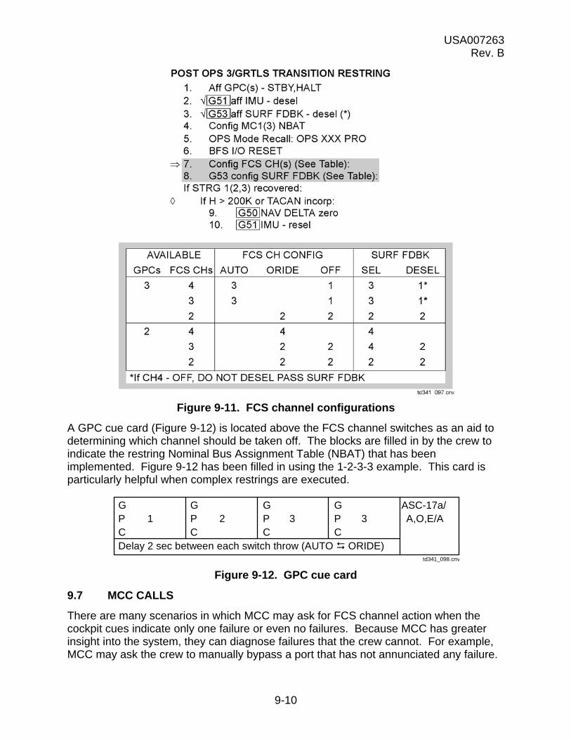
USA007263 Rev. B
9-10
Figure 9-11. FCS channel configurations
A GPC cue card (Figure 9-12) is located above the FCS channel switches as an aid to determining which channel should be taken off. The blocks are filled in by the crew to indicate the restring Nominal Bus Assignment Table (NBAT) that has been implemented. Figure 9-12 has been filled in using the 1-2-3-3 example. This card is particularly helpful when complex restrings are executed.
Figure 9-12. GPC cue card
9.7 MCC CALLS
There are many scenarios in which MCC may ask for FCS channel action when the cockpit cues indicate only one failure or even no failures. Because MCC has greater insight into the system, they can diagnose failures that the crew cannot. For example, MCC may ask the crew to manually bypass a port that has not annunciated any failure.
td341_098.cnv
G G G G ASC-17a/P 1 P 2 P 3 P 3 A,O,E/AC C C CDelay 2 sec between each switch throw (AUTO ORIDE)

USA007263 Rev. B
9-11
This may occur when MCC sees high secondary delta pressure, indicating a force fight, but the secondary delta pressure is not quite high enough to bypass automatically. The crew performs the manual bypass with an item 8 on SPEC 53. As the display indicates, the item number is the actuator number and then the channel number. For example, if MCC asked the crew to manually bypass ROB Channel 4, they would type item 8 + 34 EXEC. A down arrow would appear within the matrix, indicating that this port has been commanded to bypass (Figure 9-13).
Figure 9-13. ROB Ch 4 bypassed
9.8 BODY FLAP
As previously discussed, the BF has been designed differently from the other aerosurfaces. The BF does not have ports or servovalves, and, therefore, port bypasses cannot occur on this system. However, C&W supports several messages pertaining to the BF: Body Flap Fail, BF Hold, BF Cycle, and BDY FLP SW.
9.8.1 Body Flap Fail
If the BF fails to move to its commanded position, as indicated by the PFBs, the BODY FLAP FAIL message is generated. This command-position error may be caused by a stuck or slow BF or erroneous selected feedback. SYS SUMM 1 will indicate FAIL, as shown in Figure 9-14. One example of when the BODY FLAP FAIL message may occur is at the time an entry is performed using only one Auxiliary Power Unit (APU). Priority Rate Limiting (PRL) provides hydraulic fluid to the most essential systems, such as the elevons, and may temporarily cut off hydraulics to the BF. When the BF is commanded to move with insufficient hydraulics, the BODY FLAP FAIL message occurs.
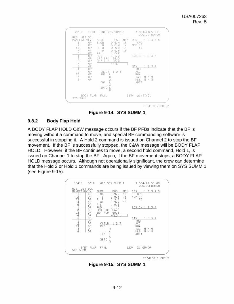
USA007263 Rev. B
9-12
Figure 9-14. SYS SUMM 1
9.8.2 Body Flap Hold
A BODY FLAP HOLD C&W message occurs if the BF PFBs indicate that the BF is moving without a command to move, and special BF commanding software is successful in stopping it. A Hold 2 command is issued on Channel 2 to stop the BF movement. If the BF is successfully stopped, the C&W message will be BODY FLAP HOLD. However, if the BF continues to move, a second hold command, Hold 1, is issued on Channel 1 to stop the BF. Again, if the BF movement stops, a BODY FLAP HOLD message occurs. Although not operationally significant, the crew can determine that the Hold 2 or Hold 1 commands are being issued by viewing them on SYS SUMM 1 (see Figure 9-15).
Figure 9-15. SYS SUMM 1

USA007263 Rev. B
9-13
9.8.3 Body Flap Cycle
If both the Hold 2 and Hold 1 commands fail to stop the BF movement, a BODY FLAP CYCLE C&W message occurs. The Hold 2 and Hold 1 commands are reissued in an attempt to stop the BF movement. SYS SUMM 1 displays the corresponding Hold 2, Hold 1, and Cycle indications. (See Figure 9-16 for cycle status.) The crew likely will have to rely on MCC calls to reconfigure the system and stop the BF movement. Taking manual BF may even be required to clear the BF commands.
9.8.4 BDY FLP SW
The BF switches are two contact switches. If the two contacts disagree with each other, the BDY FLP SW message occurs. The other BF switch can be used if manual BF is required.
Figure 9-16. SYS SUMM 1
9.9 SUMMARY
In many of the crew procedures, channel management is required when the next failure results in a one-on-one or two-on-two force fight. Although taking channels to Override does not relieve the force fight, it prevents the good channels from being bypassed. FCS channel management is usually not required for aerosurfaces during ascent or for main engine actuators during entry. Post SRB Sep, FCS channel management is not required for SRB actuator failures. MCC has much greater insight into the FCS and should be consulted to determine if FCS channel failures are real or false. Finally, the BF is designed differently than the other aerosurfaces and, therefore, there are several BF C&W messages that crewmembers should be familiar with. Again, MCC assistance may be required to reconfigure the BF system.
USA007263 Rev. B
9-14
9.10 QUESTIONS
Use the Flight Data File presented in Figure 9-1, Figure 9-5, Figure 9-6, Figure 9-11, and Figure 9-12 to determine the correct FCS channel management for the following questions.
1. During dynamic entry, SPEC 53 indicates that speedbrake Channel 2 has failed (MCC verifies that failure is real).
2. During dynamic entry, SPEC 53 indicates that speedbrake Channel 2 and LOB Channel 2 have failed (MCC verifies that failures are real).
3. During dynamic ascent, GPC 3 fails.
4. During dynamic ascent, SPEC 53 indicates that left SSME yaw Channel 3 has failed (MCC verifies that the channel failure is real), which is followed by an FA 1 MDM failure.
5. During dynamic ascent, FA 1 MDM fails, followed by an ASA 2 power failure.
6. During entry, a restring of 1-1-3-4 is performed.
7. MCC calls and asks for a manual bypass of rudder Channel 3.
8. A BODY FLAP CYCLE message occurs during dynamic entry.
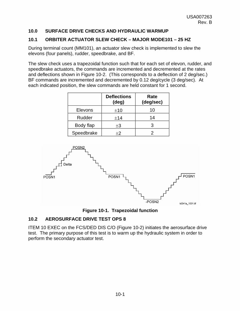
USA007263 Rev. B
10-1
10.0 SURFACE DRIVE CHECKS AND HYDRAULIC WARMUP
10.1 ORBITER ACTUATOR SLEW CHECK – MAJOR MODE101 – 25 HZ
During terminal count (MM101), an actuator slew check is implemented to slew the elevons (four panels), rudder, speedbrake, and BF.
The slew check uses a trapezoidal function such that for each set of elevon, rudder, and speedbrake actuators, the commands are incremented and decremented at the rates and deflections shown in Figure 10-2. (This corresponds to a deflection of 2 deg/sec.) BF commands are incremented and decremented by 0.12 deg/cycle (3 deg/sec). At each indicated position, the slew commands are held constant for 1 second.
Deflections (deg)
Rate (deg/sec)
Elevons 10 10
Rudder 14 14
Body flap 3 3
Speedbrake 2 2
Figure 10-1. Trapezoidal function
10.2 AEROSURFACE DRIVE TEST OPS 8
ITEM 10 EXEC on the FCS/DED DIS C/O (Figure 10-2) initiates the aerosurface drive test. The primary purpose of this test is to warm up the hydraulic system in order to perform the secondary actuator test.

USA007263 Rev. B
10-2
Figure 10-2. FCS/DED DIS C/O
a. Elevon and rudder CMD and POS are displayed in degrees.
b. Elevon POS is displayed as U (up) or D (down).
c. Rudder POS is displayed as L (left) or R (right).
d. Speedbrake CMD and POS are displayed in percent of full deflection.
e. BF CMD is displayed as remote text - either UP, DN, or blank (no drive).
f. BF POS is displayed in percent of full deflection.
The aerosurface drive test (Figure 10-3) incorporates a sawtoothed ramp function to drive the aerosurfaces cyclically between two points. The surfaces are first commanded from their current position to point 1 or Final Value 1 (FV-1) at a specified rate for each actuator. The second point is final value 2 (FV-2). The surfaces are driven between FV-1 and FV-2 until the crew performs ITEM 11 EXEC on the FCS/DED/DIS C/O. The surfaces are then commanded to final value 3 (FV-3) positions. FV-3 positions are the desired positions for performing the secondary actuator test.
The final values and drive rates for each actuator are as follows:
Actuator FV-1 FV-2 FV-3 Rate
Elevons 18 -33 -7.5 5.8 deg/sec
Rudder 5 -5 0 5.0 deg/sec
Speedbrake 10 2 10 2.7 deg/sec
Body flap 20.3 -10.5 4.5 N/A
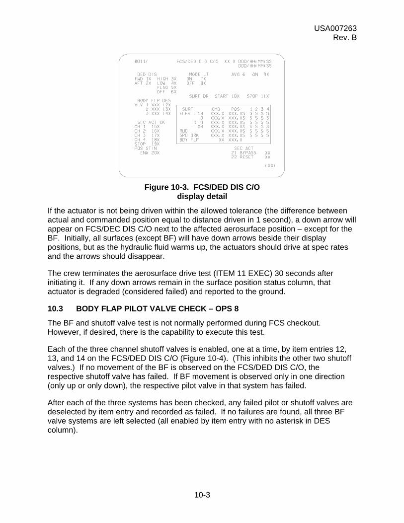
USA007263 Rev. B
10-3
Figure 10-3. FCS/DED DIS C/O display detail
If the actuator is not being driven within the allowed tolerance (the difference between actual and commanded position equal to distance driven in 1 second), a down arrow will appear on FCS/DEC DIS C/O next to the affected aerosurface position – except for the BF. Initially, all surfaces (except BF) will have down arrows beside their display positions, but as the hydraulic fluid warms up, the actuators should drive at spec rates and the arrows should disappear.
The crew terminates the aerosurface drive test (ITEM 11 EXEC) 30 seconds after initiating it. If any down arrows remain in the surface position status column, that actuator is degraded (considered failed) and reported to the ground.
10.3 BODY FLAP PILOT VALVE CHECK – OPS 8
The BF and shutoff valve test is not normally performed during FCS checkout. However, if desired, there is the capability to execute this test.
Each of the three channel shutoff valves is enabled, one at a time, by item entries 12, 13, and 14 on the FCS/DED DIS C/O (Figure 10-4). (This inhibits the other two shutoff valves.) If no movement of the BF is observed on the FCS/DED DIS C/O, the respective shutoff valve has failed. If BF movement is observed only in one direction (only up or only down), the respective pilot valve in that system has failed.
After each of the three systems has been checked, any failed pilot or shutoff valves are deselected by item entry and recorded as failed. If no failures are found, all three BF valve systems are left selected (all enabled by item entry with no asterisk in DES column).

USA007263 Rev. B
10-4
Figure 10-4. Body flap pilot valve check
10.4 SECONDARY ACTUATOR CHECK – OPS 8
The secondary actuator check is the primary test of the on-orbit checkout. It provides a means to test for failures of the secondary actuators outside the ASA fault detection (Figure 10-5).
Secondary actuator fault detection can detect a large position or rate failure by sensing excessive secondary actuator delta pressures (e.g., if one secondary actuator’s position or rate is excessively different from the other secondary actuator’s positions or rates, fault detection will bypass (or isolate) that secondary actuator). However, null failures or low rate failures may escape identification by fault detection. If a subsequent channel failure occurred for the same actuator, the result would be a two-on-two force fight and the probable bypassing by fault detection of the two good secondary actuators, leaving no control of that actuator. Since large actuator position changes at fast rates are not required until some time in entry, failures may go undetected by fault detection until that time in the mission. Therefore, the secondary actuator check performs a test for those kinds of failures.
10.4.1 Secondary Actuator Check – Channel 1
A large delta position command will be issued over secondary actuator Channel 1, while leaving the other three channels at the nominal position.
1. Check all four FCS switches in AUTO.
2. Issue the large bias command to all the actuators except the BF by item entry ITEM 15 EXEC on FCS/DED DIS C/O. An asterisk will appear beside item 15. Bias command values are elevons 6, rudder 12, and speedbrake 24.

USA007263 Rev. B
10-5
Figure 10-5. FCS/DED DIS C/O
3. Monitor the surface position on FCS/DED DIS C/O for a change of 1 to 2, which indicates that the bias command was issued and received, causing the resultant command (of all four channels) to induce a bias in the actuator positions. (The ground will monitor the secondary delta pressures for each secondary actuator for a delta pressure, indicating that the bias command was issued and a force fight has resulted.)
4. Channel 1 should now bypass all secondary actuators on Channel 1. Down arrows should appear next to each surface position (except BDY FLP) under Channel 1 on FCS/DED DIS C/O, as shown in Figure 10-5.
5. The positions should return to their initial positions (no bias), and the ground should observe the secondary actuator delta pressures returning to zero. If the results of the test occur as stated, it can be concluded that the secondary actuator channel 1 has no null failures, position, or rate mistrack failures and that the bypass monitor is functioning for the stimuli polarity used. (There is a plus and a minus polarity circuit in the bypass monitor and only one circuit will be tested, depending on whether the bias stimuli are positive or negative.)
6. Perform the ITEM 19 EXEC item entry to terminate the secondary actuator check. The asterisk is removed from item 15 and appears beside item 19. This removes the test stimuli. Place the FCS Channel 1 switch in OVERRIDE to reset the bypass discrete. All down arrows should disappear from the Channel 1 column on FCS/DED DIS C/O. Place the FCS Channel 1 switch in AUTO. This concludes the test for secondary actuator Channel 1. Repeat the five steps for Channels 2, 3, and 4.

USA007263 Rev. B
10-6
After the tests are concluded, if it is determined that a secondary actuator for an actuator is failed, the failed secondary actuator can be bypassed along with all secondary actuators on the string by placing the FCS channel switch for the affected channel to OFF. This removes power to the ASA. The individual failed secondary actuator can be bypassed manually by performing an item 21 plus the actuator number and channel number.
10.5 SURFACE TEST - OPS 8
During the on-orbit FCS checkout, aerosurface feedbacks are compared to verify their validity. If an aerosurface feedback on an FCS channel differs from the others on the same channel by a delta listed in the Orbit Ops Checklist, it is bad.
The feedbacks may be examined on SPEC 42 (Figure 10-6). If a single aerosurface has a bad feedback, probably no action will be taken other than to let RM fail it out in OPS 3. If a channel has all bad feedbacks, it will be deselected using item numbers 19 to 22 on SPEC 42.
a. The four PFBs for each surface are displayed.
b. Elevon and rudder deflections are displayed in degrees.
c. Speedbrake and BF deflections are displayed in percent (0 to 99).
d. Item numbers 19 to 22 are used to manually deselect/reselect an entire FCS channel’s position feedbacks. An asterisk next to the item number indicates deselection.
e. An M will appear adjacent to a surface position to indicate missing data.
Figure 10-6. SWITCH/SURF – OPS 8

USA007263 Rev. B
10-7
10.6 HYDRAULIC THERMAL CONDITIONING
During MMs 301, 302, and 303, the crew can initiate (item 39) and terminate (item 40) on the deorbit MNVR display, a control surface drive function that simultaneously slews the four elevons, the rudder, the speedbrake, and the BF to thermally condition the hydraulic systems for entry.
The slew commands for elevons, rudder, and speedbrake incorporate a triangular function and, for the BF, an integer (1) command (Figure 10-7). Each aerosurface is commanded from the initial position to an upper limit and then to a lower limit, incremented each cycle by a constant delta. The surfaces are repeatedly driven between limits until the surface drive function is terminated.
The surface positions are displayed on the SPI while the slew function is operating.
The slew deflection limits are as follows:
Upper Lower
Elevons +18 -33
Rudder +5 -5
Speedbrake +10 +2
Body flap +20.3 -10.5
Figure 10-7. Triangular function
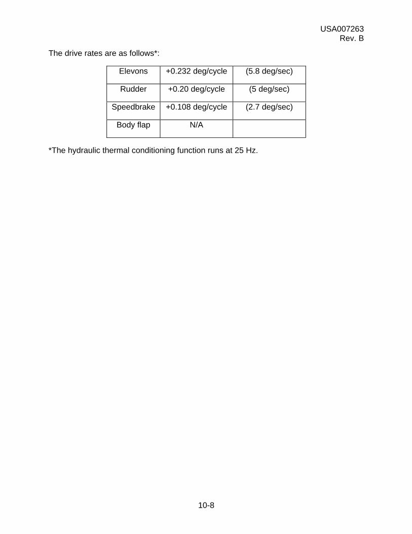
USA007263 Rev. B
10-8
The drive rates are as follows*:
Elevons +0.232 deg/cycle (5.8 deg/sec)
Rudder +0.20 deg/cycle (5 deg/sec)
Speedbrake +0.108 deg/cycle (2.7 deg/sec)
Body flap N/A
*The hydraulic thermal conditioning function runs at 25 Hz.
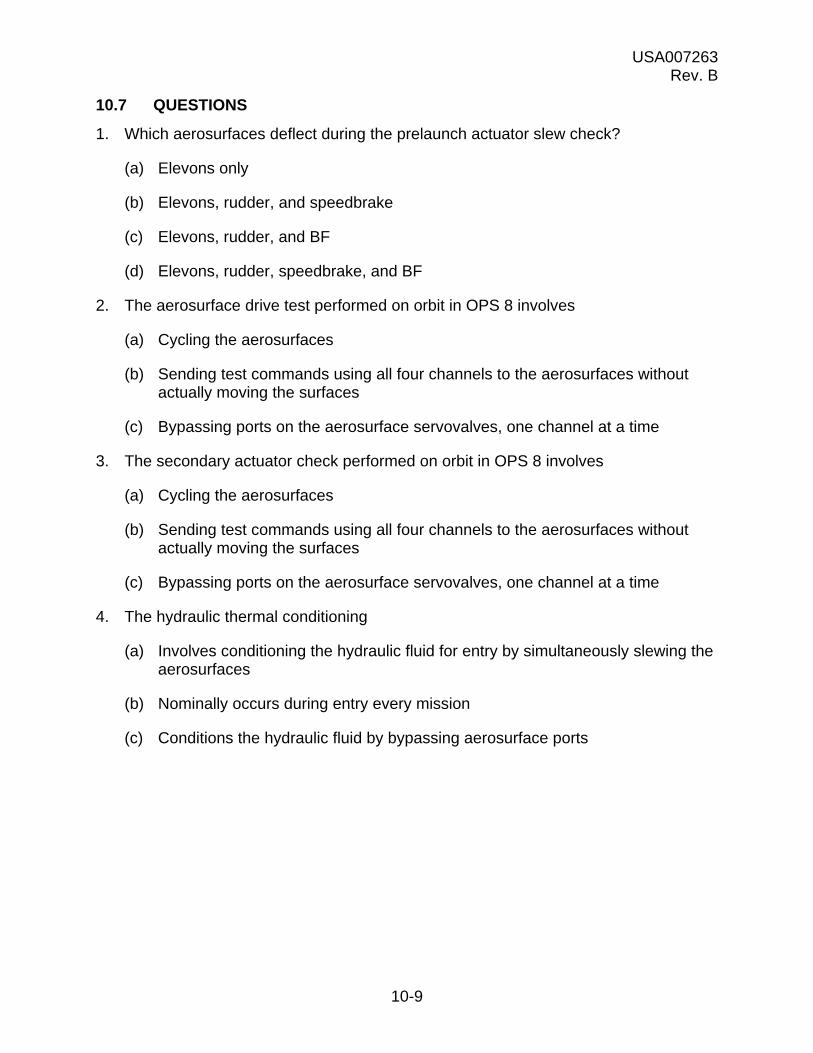
USA007263 Rev. B
10-9
10.7 QUESTIONS
1. Which aerosurfaces deflect during the prelaunch actuator slew check?
(a) Elevons only
(b) Elevons, rudder, and speedbrake
(c) Elevons, rudder, and BF
(d) Elevons, rudder, speedbrake, and BF
2. The aerosurface drive test performed on orbit in OPS 8 involves
(a) Cycling the aerosurfaces
(b) Sending test commands using all four channels to the aerosurfaces without actually moving the surfaces
(c) Bypassing ports on the aerosurface servovalves, one channel at a time
3. The secondary actuator check performed on orbit in OPS 8 involves
(a) Cycling the aerosurfaces
(b) Sending test commands using all four channels to the aerosurfaces without actually moving the surfaces
(c) Bypassing ports on the aerosurface servovalves, one channel at a time
4. The hydraulic thermal conditioning
(a) Involves conditioning the hydraulic fluid for entry by simultaneously slewing the aerosurfaces
(b) Nominally occurs during entry every mission
(c) Conditions the hydraulic fluid by bypassing aerosurface ports
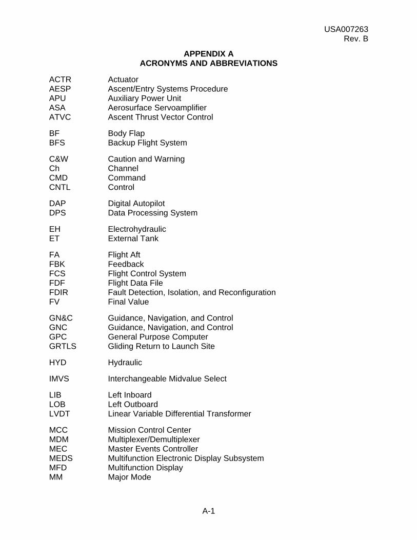
USA007263 Rev. B
A-1
APPENDIX A ACRONYMS AND ABBREVIATIONS
ACTR Actuator AESP Ascent/Entry Systems Procedure APU Auxiliary Power Unit ASA Aerosurface Servoamplifier ATVC Ascent Thrust Vector Control
BF Body Flap BFS Backup Flight System
C&W Caution and Warning Ch Channel CMD Command CNTL Control
DAP Digital Autopilot DPS Data Processing System
EH Electrohydraulic ET External Tank
FA Flight Aft FBK Feedback FCS Flight Control System FDF Flight Data File FDIR Fault Detection, Isolation, and Reconfiguration FV Final Value
GN&C Guidance, Navigation, and Control GNC Guidance, Navigation, and Control GPC General Purpose Computer GRTLS Gliding Return to Launch Site
HYD Hydraulic
IMVS Interchangeable Midvalue Select
LIB Left Inboard LOB Left Outboard LVDT Linear Variable Differential Transformer
MCC Mission Control Center MDM Multiplexer/Demultiplexer MEC Master Events Controller MEDS Multifunction Electronic Display Subsystem MFD Multifunction Display MM Major Mode

USA007263 Rev. B
A-2
MOM Moment MPS Main Propulsion System msec millisecond MTR motor MVS Midvalue Select
NBAT Nominal Bus Assignment Table
OMS Orbital Maneuvering System OPS Operational Sequence ORIDE Override
PASS Primary Avionics Software System PDU Power Drive Unit PFB Position Feedback POS Position PRL Priority Rate Limiting psf pounds per square foot psi pounds per square inch psid pounds per square inch differential
RCS Reaction Control System RHC Rotational Hand Controller RIB Right Inboard RM Redundancy Management ROB Right Outboard RPC Remote Power Controller RPTA Rudder Pedal Transducer Assembly RVDT Rotary Variable Differential Transducer
SAT Saturation SBK Speedbrake SBTC Speedbrake/Thrust Controller SF Selection Filter SOP Subsystem Operating Program SPBK Speedbrake SPDBRK Speedbrake SPD BRK Speedbrake SPD/BRK Speedbrake SPI Surface Position Indicator SRB Solid Rocket Booster SSME Space Shuttle Main Engine
USA United Space Alliance
TE Trailing Edge
VLV Valve

USA007263 Rev. B
B-1
APPENDIX B ANSWERS
Section 2
1. During first stage, the major portion of vehicle steering is provided by gimbaling the SRB nozzles. During second stage, SSME gimbaling provides vehicle control.
2. During entry, the BF is used to help keep the elevons on their schedule and to provide pitch trim in the vehicle. It also provides an auxiliary function of shielding the main engines from entry heating.
3. The speedbrake provides pitch trim from Mach 10 to Mach 1. From Mach 1 until landing, it is used to control vehicle energy. At main gear touchdown, it is commanded full open to aid nose gear derotation.
4. The crew can see aerosurface positions on PASS GNC SYS SUMM 1 and on the surface position indicator.
5. A servovalve converts an electrical position command into a proportional hydraulic pressure.
6. Secondary P is the hydraulic pressure created within a servovalve in response to an electrical position command.
7. If an ASA or ATVC detects secondary P above 2200 psi for main ports or 2025 psi for aerosurface ports for more than 120 msec, it will open that servovalve’s isolation valve. This will cause hydraulic pressure from the servovalve to be bypassed.
8. In both cases, taking an FCS CH switch to ORIDE will reset all actuator ports on that channel. Ports on aerosurfaces may also be reset by using the FCS DED DIS C/O in OPS 8 or SPEC 53 in OPS 1, 6, and 3.

USA007263 Rev. B
B-2
Section 3
1. An ATVC is composed of a power supply and 10 circuits or drivers, 6 for the MPS and 4 for the SRBs.
2. Redundant channel equalization is logic within an ASA or ATVC that monitors secondary P and tries to reduce it by biasing the actuator command to keep it below 1175 psi.
3. P fault detection is logic that monitors secondary P and opens the servovalve’s isolation valve when secondary P exceeds 2200 psi for 120 msec.
4. The override monitor looks for override commands, resetting ports and overriding P fault detection logic if they are present.

USA007263 Rev. B
B-3
Section 4
1. During ascent, the elevons are used to reduce aerodynamic loads on the wings. The other aerosurfaces are not used.
2. Three control buses are routed through the ASA power switch. Two of them go to the ASA power supply, and one powers the ASA isolation valve driver.
3. Turning off an FCS CH switch interrupts control bus power to the ASA, causing the ASA internal power supply to fail off. Because isolation valve driver power is routed through the ASA power switch, all ports on that FCS CH should bypass.
4. An ASA is composed of a power supply, four elevon drivers, one rudder driver, one speedbrake driver, and one circuit for the BF.
5. Redundant channel equalization activates when secondary P exceeds 1250 psi for more than 3.6 sec.
6. When secondary P rises above 2025 psi for more than 120 msec, P fault detection logic will isolate the servovalve port.
7. Primary P is the hydraulic pressure within the aerosurface primary actuator. The GPCs use it to calculate elevon hinge moment.
8. The only difference between the elevons and rudder/speedbrake drivers is that primary P is not fed to or used by the latter.
9. The BF channel in ASA 4 is used to pass feedbacks only. The BF channels in ASAs 1 through 3 receive both commands and feedbacks.
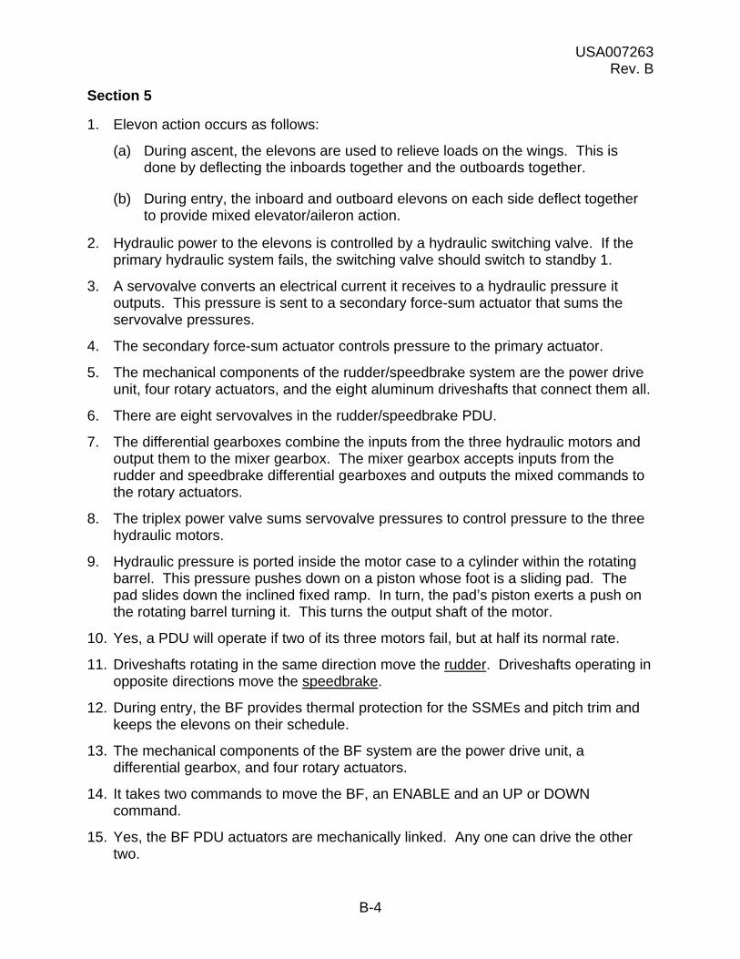
USA007263 Rev. B
B-4
Section 5
1. Elevon action occurs as follows:
(a) During ascent, the elevons are used to relieve loads on the wings. This is done by deflecting the inboards together and the outboards together.
(b) During entry, the inboard and outboard elevons on each side deflect together to provide mixed elevator/aileron action.
2. Hydraulic power to the elevons is controlled by a hydraulic switching valve. If the primary hydraulic system fails, the switching valve should switch to standby 1.
3. A servovalve converts an electrical current it receives to a hydraulic pressure it outputs. This pressure is sent to a secondary force-sum actuator that sums the servovalve pressures.
4. The secondary force-sum actuator controls pressure to the primary actuator.
5. The mechanical components of the rudder/speedbrake system are the power drive unit, four rotary actuators, and the eight aluminum driveshafts that connect them all.
6. There are eight servovalves in the rudder/speedbrake PDU.
7. The differential gearboxes combine the inputs from the three hydraulic motors and output them to the mixer gearbox. The mixer gearbox accepts inputs from the rudder and speedbrake differential gearboxes and outputs the mixed commands to the rotary actuators.
8. The triplex power valve sums servovalve pressures to control pressure to the three hydraulic motors.
9. Hydraulic pressure is ported inside the motor case to a cylinder within the rotating barrel. This pressure pushes down on a piston whose foot is a sliding pad. The pad slides down the inclined fixed ramp. In turn, the pad’s piston exerts a push on the rotating barrel turning it. This turns the output shaft of the motor.
10. Yes, a PDU will operate if two of its three motors fail, but at half its normal rate.
11. Driveshafts rotating in the same direction move the rudder. Driveshafts operating in opposite directions move the speedbrake.
12. During entry, the BF provides thermal protection for the SSMEs and pitch trim and keeps the elevons on their schedule.
13. The mechanical components of the BF system are the power drive unit, a differential gearbox, and four rotary actuators.
14. It takes two commands to move the BF, an ENABLE and an UP or DOWN command.
15. Yes, the BF PDU actuators are mechanically linked. Any one can drive the other two.

USA007263 Rev. B
B-5
Section 6
1. The aeroactuator SOP converts GPC-generated aerosurface position commands to volts dc that the ASA can use.
2. Elevon feedback RM consists of fault detection, isolation, and reconfiguration, and the selection filter.
3. Elevon PFB FDIR compares feedbacks on Channels 1, 2, and 3 against each other by comparing their differences against an I-loaded limit. If two of the three limit checks fail the comparison, the common parameter is declared failed. FDIR substitutes the Channel 4 value for the failed value and terminates processing. The three remaining values go to the SF.
4. The SF may be downmoded by commfaults or by crew deselection of SURF FDBK items on SPEC 53.
5. Elevon PFB FDIR runs in OPS 3 and OPS 6 (MM602 and MM603).
6. There is no FDIR. The selection filter initially does an IMVS.
7. Elevon P FDIR checks Ps on Channels 1, 2, and 3 against each other by subtracting each from the other and comparing their differences against an I-loaded limit. If two of the three checks fail, the parameter common to them is declared failed. The Channel 4 value is substituted for the bad parameters and is sent with the two other good values to the SF. FDIR terminates processing. The SF will downmode after this only for commfaults.
8. Eight position feedbacks come back from the rudder/speedbrake (four each).
9. FDIR and SF run in OPS 3 and OPS 6 (MM602 and MM603).
10. If the BF UP command on FCS CH 1 fails on, a command will be sent over FCS CH 2 to hold the BF where it is. The crew is issued a HOLD 2 message on GNC SYS SUMM 1. If this holds the BF, an SM alert and a BODY FLAP HOLD message are issued. If that does not work, the same thing is attempted over FCS CH 1. A BODY FLAP CYCLE message will be issued if this hold also fails to work.
11. A BF fail occurs when BF RM sees a command but no corresponding BF motion, and a HOLD does not exist.
12. BF PFB RM uses a quad MVS scheme on all four PFBs. It then sends the selected PFB to FDIR, which compares the differences between each PFB and the selected PFB to an I-loaded limit. The selected PFB is also sent to the GPCs. Upon a first failure, FDIR will declare the failure, downmode the SF to MVS, and terminate processing.

USA007263 Rev. B
B-6
Section 7
1. The SPI is the surface position indicator, a gauge mounted on Panel F6 that shows aerosurface positions. It works in OPS 3, 8, and MM602 and MM603.
2. If the BF is in trail, the BF position indicator will match the position of the small triangle just above 40 on the SPI.
3. In MM304, 305, 602, and 603, when q >50 psf and the pitch jets are off, both lights will illuminate when elevon rate saturation occurs.
4. To see which aerosurfaces generated an FCS SAT message, you would look at PASS GNC SYS SUMM 1.
5. To determine what has happened if you get an FCS CH 3 message and a down arrow on GNC SYS SUMM 1, you would look at SPEC 53.

USA007263 Rev. B
B-7
Section 8
1. A down arrow next to the SURF FDBK (item 19) on SPEC 53 indicates that a position feedback on one aerosurface of FCS CH 2 has failed RM.
2. If LOB Channel 3 receives a command bias, a three-on-one force fight will occur, resulting in higher secondary P on this port. If the secondary P exceeds 2025 psi, the port bypasses.
3. If a GPC/MDM fails, this channel feedback is commfaulted. FDIR will substitute Channel 4 feedback for the commfaulted channel, then quit.
4. ASA 3 internal power failure has most likely occurred if you see a column of down arrows along the Channel 3 AERO PORT STAT and a down arrow next to Channel 3 SURF FDBK DES on SPEC 53.
USA007263 Rev. B
B-8
Section 9
1. No action is necessary because this is the first failure on the speedbrake actuator.
2. No action is necessary because the failures occurred on separate actuators.
3. Move FCS Channel 3 switch to off. Deselect surface feedbacks on Channel 3.
4. Take FCS Channel 1 switch to off. Place FCS Channels 2 and 4 switches in override (with a 2-second delay between switch throws). Deselect feedbacks on FCS Channel 1.
5. Configure FCS Channel 1 switch to off. Deselect feedbacks on FCS Channel 1. No action is required for the ASA failure because the failure occurred on ascent.
6. Fill out the GPC cue card for the restring of 1-1-3-4. This will require either Channel 1 or 2 switch be taken off. Assuming no other failures, either switch can be taken to off. Deselect the corresponding position feedbacks (i.e., if FCS Channel 1 switch is taken off, deselect Channel 1 position feedbacks).
7. Perform the manual bypass by using SPEC 53 item 8 + 53. A down arrow should appear in the matrix for rudder Channel 3.
8. The crew should realize that the BF is experiencing uncommanded movement if a BODY FLAP CYCLE message occurs during dynamic entry. MCC assistance is probably required to reconfigure the BF because the crew has limited BF insight.
USA007263 Rev. B
B-9
Section 10
1. (d) The aerosurfaces that deflect during the prelaunch actuator slew check are the elevons, rudder, speedbrake, and body flap.
2. (a) The aerosurface drive test performed on orbit on OPS 8 involves cycling the aerosurfaces.
3. (c) The secondary actuator check performed on orbit in OPS 8 involves bypassing ports on the aerosurface servovalves, one channel at a time.
4. (a) Hydraulic thermal conditioning involves conditioning the hydraulic fluid for entry by simultaneously slewing the aerosurfaces.
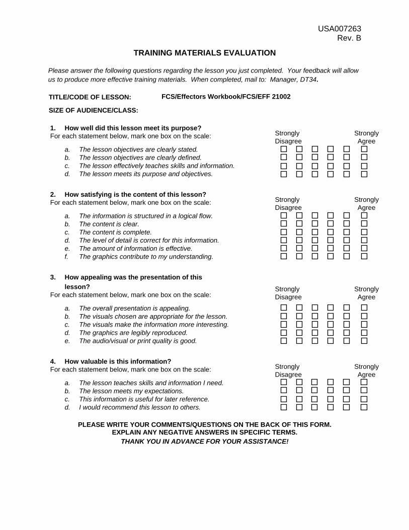
USA007263 Rev. B
TRAINING MATERIALS EVALUATION
Please answer the following questions regarding the lesson you just completed. Your feedback will allow us to produce more effective training materials. When completed, mail to: Manager, DT34.
TITLE/CODE OF LESSON: FCS/Effectors Workbook/FCS/EFF 21002 SIZE OF AUDIENCE/CLASS: 1. How well did this lesson meet its purpose? For each statement below, mark one box on the scale:
a. The lesson objectives are clearly stated. b. The lesson objectives are clearly defined. c. The lesson effectively teaches skills and information. d. The lesson meets its purpose and objectives.
Strongly Strongly Disagree Agree
2. How satisfying is the content of this lesson? For each statement below, mark one box on the scale:
a. The information is structured in a logical flow. b. The content is clear. c. The content is complete. d. The level of detail is correct for this information. e. The amount of information is effective. f. The graphics contribute to my understanding.
Strongly Strongly Disagree Agree
3. How appealing was the presentation of this
lesson? For each statement below, mark one box on the scale:
a. The overall presentation is appealing. b. The visuals chosen are appropriate for the lesson. c. The visuals make the information more interesting. d. The graphics are legibly reproduced. e. The audio/visual or print quality is good.
Strongly Strongly Disagree Agree
4. How valuable is this information? For each statement below, mark one box on the scale:
a. The lesson teaches skills and information I need. b. The lesson meets my expectations. c. This information is useful for later reference. d. I would recommend this lesson to others.
Strongly Strongly Disagree Agree
PLEASE WRITE YOUR COMMENTS/QUESTIONS ON THE BACK OF THIS FORM. EXPLAIN ANY NEGATIVE ANSWERS IN SPECIFIC TERMS.
THANK YOU IN ADVANCE FOR YOUR ASSISTANCE!

DOCUMENT NUMBER: USA007263Rev. B
TITLE: FCS Effectors Workbook FCS/EFF 21002
*Hard copy distribution. Submit distribution changes to the DT34 manager. Most documents are available electronically via USA Intranet Web (usa1.unitedspacealliance.com), Space Flight Operations Contract (SFOC), SFOC Electronic Library System (SELS).
NASA-JSC
DA83 MOD Library *DT34 Library
USA-HOUSTON
*USH-121G SFOC Technical Library