fcs series ii - ametek programmable power fcs series ii ac power system is one of the most power...
TRANSCRIPT

www.california-instruments.com ISO 9001:2000
Integrated SystemThe FCS Series II AC Power system is one of the most power systems in the industry, supporting high power levels with ease, at a reduced cost. The FCS Series II combines a flexible AC power source with a harmonic power analyzer that is capable of handling the most complex applications.
The FCS Series II uses a state-of-the-art Digital Signal Processor in conjunction with precision A/D converters. This provides more accuracy and resolution for test applications then is found in most dedicated harmonic power analyzers.
This system integrates digital multimeters, power harmonics analyzer, and current shuts, eliminating the need for multiple instruments; thus reducing cost and providing more flexibility than can be found with competing products.
Easy To Use ControlsThe FCS Series II is microprocessor controlled and is operated using the front panel keypad that makes precise entries simple, and our powerful Instrume Control Software which offers an even higher level of programability. An analog control allows output voltage and frequency to be slewed up or down dynamically. The control employs a dynamic rate change algorithm that combines the benfits of precist control over small parameter changes with quick sweeps through the entire range.
ApplicationsWith precise output regulation and accuarcy, high load drive current, multi or single phase mode, and built-in power analyzer measurement capabilities, the FCS Series II Power System addresses many application areas for AC power testing. Additional features like line arbitrary waveform generation, DO 160, MIL 704, and Airbus test standards make the FCS Series II a great choice for avionics and defense applications.
Product Evaluation and TestX
High Performance135/270 V, 156/312 V, or 200/400 V
Easy to ProgramUses front panel keyboard display with full decimal keypad for data entry
Single or Three Phase OperationIdeally suited for avionics and defense applications
Arbitrary Waveform CapabilityTest products for harmonics susceptibility
Power Power AnalyzerPerforms voltage and load current harmonic analysis and waveform acquisition
Features multiple ConnectivityConnects via RS232, USB, and GBIB - remote control interface for ATE system integration included
FCS Series II High-Power Systems
18kVA-54kVA Programmable AC
Power Source / Analyzer

www.california-instruments.comISO 9001:2000
FCS Series II - Measurement and Analysis
FCS Series II Series - Configuration Options
Standard Waveforms
The FCS Series II Series provides three standard waveforms that are always available for output. The standard waveforms are:
• Sinewave for normal AC applications.
• Squarewave for special applications.
• Clipped Sinewave - Simulates THD levels to test for harmonic distortion susceptibility.
In addition to these standard waveforms, user defined waveform can be downloaded over the bus.
Harmonic Waveform Generation
Using the latest DSP technology, the FCS Series II Series controller is capable of generating harmonic waveforms to test for harmonics susceptibility of a unit under test. The Instrument Control Software can be used to define harmonic waveforms by specifying amplitude and phase for up to 50 harmonics. The waveform data points are generated and downloaded by the Instrument Control Software to the AC source through either the Remote Interface bus and remain in nonvolatile memory. Up to 50 waveforms can be stored and given a user defined name for easy recall.
The three phase FCS Series II configuration offers independent waveform generation on each phase allowing three phase anomalies to be programmed and also allows simulation of unbal-anced line conditions.
Arbitrary Waveform Generation Using the provided Instrument Control Software, the user also has the ability to define arbitrary AC waveforms. The arbitrary waveform method of data entry provides an alterna-tive method of specifying AC anomalies by providing specific waveform data points. The Instrument Control Software includes a catalog of custom waveforms.
Arbitrary waveform capability is a flexible way of simulating the effect of real-world AC power line conditions in both engineering and production environments.
Harmonic waveform, Fund., 3rd, 5th, 7th and 9th.
Simulation of severe ringing on the output of a UPS.
AC Transient Generation
The FCS Series II controllers have a powerful AC transient generation system that allows complex sequences of voltage, frequency and waveshapes to be generated. This further enhances the capability to simulate AC line conditions or disturbances. When combined with the multi phase arbitrary waveform capabilities, the AC output possibilities are truly exceptional. In three phase system configurations, transient generation is controlled independently yet time synchronized on all three phases. Accurate phase angle control and synchronized transient list execution provide unparalleled accuracy in positioning AC output events.
Transient programming is easily accomplished from the front panel or software where clearly laid out menu’s guide the user through the transient definition process. This feature allows for transient execution, Start, Stop, Abort and Resume operations.
User defined transient sequences can be saved to nonvolatile memory on on the PC for instant recall and execution at a later time. The included Instrument Control Software supports transient defini-tions using a spreadsheet-like data entry grid. A library of frequently used transient programs can be created on disk.
Voltage sweep transient causes output voltage to change at a programmed rate.
www.california-instruments.com ISO 9001:2000
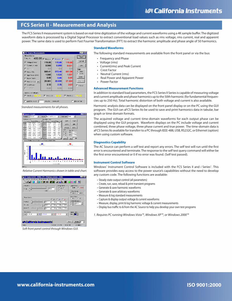
FCS Series II - Measurement and Analysis
Standard Waveforms
The following standard measurements are available from the front panel or via the bus:
• Frequency and Phase • Voltage (rms) • Current(rms) and Peak Current • Crest Factor • Neutral Current (rms) • Real Power and Apparent Power • Power Factor
Advanced Measurement FunctionsIn addition to standard load parameters, the FCS Series II Series is capable of measuring voltage and current amplitude and phase harmonics up to the 50th harmonic (for fundamental frequen-cies up to 250 Hz). Total harmonic distortion of both voltage and current is also available.
Harmonic analysis data can be displayed on the front panel display or on the PC using the GUI program. The GUI can aFCS Series IIo be used to save and print harmonics data in tabular, bar graph or time domain formats.
The acquired voltage and current time-domain waveforms for each output phase can be displayed using the GUI program. Waveform displays on the PC include voltage and current combined, three phase voltage, three phase current and true power. The time-domain data is aFCS Series IIo available for transferr to a PC through IEEE-488, USB, RS232C, or Ethernet (option) when using custom software.
Diagnostics CapabilityThe AC Source can perform a self test and report any errors. The self test will run until the first error is encountered and terminate. The response to the self test query command will either be the first error encountered or 0 if no error was found. (Self test passed).
Instrument Control SoftwareWindows® Instrument Control Software is included with the FCS Series II and i Series1 . This software provides easy access to the power source’s capabilities without the need to develop any custom code. The following functions are available:
• Steady state output control (all parameters)• Create, run, save, reload & print transient programs• Generate & save harmonic waveforms • Generate & save arbitrary waveforms • Measure & log standard measurements• Capture & display output voltage & current waveforms • Measure, display, print & log harmonic voltage & current measurements• Display bus traffic to & from the AC Source to help you develop your own test programs
1. Requires PC running Windows Vista™, Windows XP™, or Windows 2000™
Standard measurements for all phases.
Relative Current Harmonics shown in table and chart.
Soft front panel control through Windows GUI.
The FCS Series II measurement system is based on real-time digitization of the voltage and current waveforms using a 4K sample buffer. The digitized waveform data is processed by a Digital Signal Processor to extract conventional load values such as rms voltage, rms current, real and apparent power. The same data is used to perform Fast Fourrier Transformation (FFT) to extract the harmonic amplitude and phase angle of 50 harmonics.

www.california-instruments.comISO 9001:2000
FCS Series II - Specifications
OutputMaximum Power per phase: FCS18-1 (1 phase): 18 kVA; FCS18-3 (3 phase): 6 kVA
Power factor: 0 to unity at full output VA
Voltage Ranges:Range: V Low V High
AC 0-135 V 0-270 V
See -HV and EHV options for alternative voltage range pairs.
VA Programming Resolution: 100 mV
Load Regulation: < 0.1 % FS
Line Regulation: < 0.02 % for 10 % line change
Programming Accuracy (25°C ±5°C): ± (0.05% + 0.25 V) from 10V to FS. Specified at voltage sense point with ALC mode ON.
Frequency Range: 45 Hz - 1200 Hz (see -HF option for higher output frequencies)
Frequency Resolution: 0.01 Hz at < 81.9 Hz, 0.1 Hz at 82.0 to 819.1 Hz, 1 Hz at > 819 Hz
Max RMS Current:
Range: FCS18-1 FCS18-3
0-135 V 133.2 Arms 44.4 Arms
0-270 V 66.6 Arms 22.2 Arms
Note: Constant power mode on the FCS Series II provides increased current at reduced voltage
Current Limit: Programmable from 0 Amps to maximum current for selected range
Peak Current: 5.7 X (lrms @ full scale voltage)
Output Noise: 100mV rms typ. (20 kHz to 1 MHz) Harmonic Distortion: < 1% (at full scale voltage, full resistive load)
Isolation Voltage: 300 V rms output to chassis Output Relay: Push button controlled and bus controlled output relay
Input
Line Voltage/Current (rms per phase):
Models: 208 VAC (STD) 240 VAC (OPT) 380 VAC (OPT) 415 VAC (OPT) 480 VAC (OPT)
Line Voltage: ± 10% ± 10% ± 10% ± 10% ± 10%
Line Current: 65 Arms 56 Arms 36 Arms 33 Arms 28 Arms
Line VA: 24 KVA at nominal input voltage
Line Frequency: 47-63 Hz
Efficiency: 85% (Typical) depending on line and load
Power Factor: 0.85 (Typical)
Inrush Current: 250 Apk max. (Note: Each FCS chassis requires its own AC service).
Hold-up Time: > 10 ms
Isolation Voltage: 400 VAC RMS input to output; 1350 VAC input to chassis
MeasurementVoltage: Resolution 0.1 Volt, Accuracy 0.05% + 0.25%, Range 0 - 400 V
Current: Resolution 0.01 Amp, Accuracy 0.1% + 0.15A, Range 0 - 20 Amps
Power: Resolution 0.01 kW, Accuracy 1.0 % FS, Range 0 - 54 KW
Phase Angle: Resolution 0.1°, Accuracy ± 2°, Range 0 - 360 °
Power Factor: Range 0.00 to 1.00
Frequency: Resolution four decades, Accuracy ± 0,02 Hz to 99.99 Hz, ± 0.2 Hz to 500.0 Hz, ± 0.5 Hz to 999.9 Hz, ± 10 Hz to 1200 Hz
Apparent Power: Resolution 0.01 kVA, Accuracy 1.0 % FS, Range 0 - 54 KVA
SystemStorage: Setup: 16 complete instrument setups / Transient List: 100 transient steps per list (SCPI mode) or 16 transient registers (APE mode)
Trigger Input/Output: Input: Triggers measurements or transient steps - SMA connector: 10K pull-up / Output: SMA Connector: HCTTL output
Protection
Overload/Temp/Voltage: Overload: Constant current or constant voltage mode; Over temperature: Automatic Shutdown; Over voltage: Surge protection to withstand EN50082-1 (IEC 801-4, 5) levels.
Regulatory/RFI Suppresion: IEC1010, EN50081-2, EN50082-2, CE, EMC, and safety mark requirements / RIF Suppression: CISPR 11, Group1, Class A
Note: Specifications are subject to change without notice. Specifications are warranted over an ambient temperature range of 25°± 5° C. Unless otherwise noted, specifications are per phase for a sinewave with a resistive load and apply after a 30 minute warm-up period. For three phase configurations, all specifications are for L-N. Phase angle specifications are valid under balanced load conditions only.

www.california-instruments.com ISO 9001:2000
FCS Series II - SpecificationsRemote Control
IEEE-488 Interface (option): IEEE-488 (GPIB) talker listener. Subset: AH1, C0, DC1, DT1, L3, PP0, RL2, SH1, SR1, T6, IEEE-488.2 SCPI Syntax
USB Interface & Ethernet: Version: USB 1.1; Speed: 460 Kb/s maximum / Ethernet Interface (Optional): specify -LAN option. 10BaseT, 100BaseT, RJ45
RS232C Interface: Bi-directional serial interface; 9-pin D-shell connector. Handshake: CTS, RTS. Databits: 7 w/ parity, 8 w/o parity. Stopbits: 2. Baud rate: 9600 to 115200. Supplied with RS232C cable / Code and Format: SCPI; APE (option -GPIB)
Physical DimensionsDimensions (per chassis): Height: 45” (114.3 cm), Width: 30” (76.2 cm), Depth: 36” (+ 4” for J-box) = 40” (101.6 cm) (For /2 or /3 models multiply height by 2/3)
Weight: Chassis: Net: 900 lbs / 87.7 Kg, Shipping: 1100 lbs / 127.3 Kg (for /2 or /3 model configuarations multiply number of chassis).
Vibration and Shock: Designed to meet NSTA project 1A transportation leveI
Air Intake/Exhaust: Forced air cooling, front to rear air intake, rear exhaust, variable fan speed
Temperature: Operating: 0 to 35° C, full power / Storage: -40 to +85° C
Diagnostics: Built-in self test available over bus (*TST)
Rear Panel Connectors:* Three phase AC input and output terminal block with safety cover. * IEEE-488 (GPIB) connector, USB connector, RJ45 connector (with -LAN Option). * 9-pin D-Shell RS232C connector (RS232 DB9 to DB9 cable supplied). * Remote Inhibit (INH) and Discrete Fault Indicator (DFI). * Remote voltage sense terminal block. * Trigger In1 and Trigger Out1. * System interface connectors. * Auxilary Output (Option -AX)
Option -ADV Specifications
Measurements - Harmonics:
Parameter Frequency Fundamental Harmonics Voltage Current
Range 45-250 Hz / 0.09 - 12.5 kHz Fundamental Harmonics 2 - 50 Fundamental Harmonics 2 - 50
Accuracy* (±) 0.01% + 1 digit / 0.5% + 1 digit 750 mV 0.3% + 750 mV+0.3% /1 kHz 0.5 A / 0.3% + 150 mA +0.3% /1 kHz
Resolution 0.01 Hz / 0.1 Hz 10 mV / 10 mV 10 mA / 10 mA * Accuracy specifications are in a percent of reading for single unit in 3-phase mode.
Waveforms: Pre defined: Sine, Square, Clipped User defined, 1024 addressable data points; Storage: 50 user waveforms, non-volatile memory
Data Acquisition: Parameters: Voltage, Current time domain, per phase; Resolution: 4096 data points, 10.4 usec (1ø) or 31.25 usec (3ø) sampling interval
Option -HV SpecificationsVoltage/Frequency Ranges: Low: 0-156 Volt; High: 0-312 Volt
Max RMS Current at FSVoltage:
3 Phase: High: 38 A, Low: 19 A; 1 Phase: High 57 A, Low: 115 A
Standard -EHV SpecificationsVoltage/Frequency Ranges: Voltage: Low: 0-200 Volt; High: 0-400 Volt / Frequency: With -HF option: 45 Hz - 2000 Hz
Max RMS Current @ FS VA: 3 Phase: High: 15 A, Low: 30 A; 1 Phase: High 45 A, Low: 90 A
Note: Specifications are subject to change without notice. Specifications are warranted over an ambient temperature range of 25°± 5° C. Unless otherwise noted, specifications are per phase for a sinewave with a resistive load and apply after a 30 minute warm-up period. For three phase configurations, all specifications are for L-N. Phase angle specifications are valid under balanced load conditions only.

www.california-instruments.com
9689 Towne Centre Drive, San Diego, CA 92121-1964 l (858) 677-9040 l FAX: (858) 677-0940 l [email protected]© Copyright 2007, California Instruments Corp. Specifications subject to change without notice Printed in the USA FCSII 10/07
Ordering Information Feature Comparison
FCS Series II Rear Panel
Note: Specifications are subject to change without notice. Specifications are warranted over an ambient temperature range of 25°± 5° C. Unless otherwise noted, specifications are per phase for a sinewave with a resistive load and apply after a 30 minute warm-up period. For three phase configurations, all specifications are for L-N. Phase angle specifications are valid under balanced load conditions only.
Ordering Information
ModelRefer to table shown for model numbers and configurations. Specify number of output phases (-1 or -3) as part of model number.
Supplied withUser / Programming Manual on CD-ROM, Software and RS232C serial cable.
Output Options-AX1 Auxiliary outputs, 26
VAC, 5 VAC. Limits upper frequency to 800 Hz.
-HV1 156/312 V output range.-EHV1 200/400 V output range.-HF1 Extends upper frequency
limit. See HF table.
-LF1 Limits output frequency to 500 Hz.
Controller Options-160 RTCA/DO-160D, Change 2,
EuroCAE-14D and Airbus test firmware [Section 16, AC only. Refer to -160 option data sheet for detaiIs]
-704 Mil-Std 704 rev D and E test firmware. [AC only, Refer to -704 option data sheet for detaiIs]
-704F Mil Std 704 test firmware. Revisions A-F.
-ABD Airbus Directive 0100.1.8 tests. [AC only]. Requires -ADV and use of Windows PC and included FCS Series II Instrument Control software.
-ADV Advanced feature set. Adds arbitrary waveform generation and harmonic analysis of voltage and current.
-AMD Airbus AMD24C Tests. Revision C.
-B787 Boeing 787B3-0147 Tests.-EXS External Sync.-GPIB GPIB interface and APE
programming language.-LAN Ethernet Interface.-MB Multi-box. Adds controller
to auxiliary chassis of multi-chassis systems.
-MODE Adds phase mode selections for -3 models.
-L22 Locking Knobs.-LKM1 Clock and Lock Master-LKS1,2 Clock and Lock Auxiliary-LNS2 Line Sync.-EXS2 External Sync.
Cabinet OptionsC prefix Cabinet System. Installed and
pre-wired in 19” cabinet.
HF LF HV EHV LKM LKS EXS AX
HF - x o o x x o x
LF x - o o o o o o
HV o o - x o o o o
EHV o o x - o o o o
LKM x o o o - x o o
LKS x o o o x - x o
EXS o o o o o x - o
AX x o o o o o o -
Option Matrix:Note that some options are mutually ex-clusive as indicated in the table below. An ‘o’ means the options can be combined. An ‘x’ means they cannot.
C
FG
H
H