fe safety analysis of a high speed wood planer cutter19175/fulltext01.pdffe safety analysis of a...
TRANSCRIPT

FE safety analysis of a high speed wood planer cutter
An alternative method to achieve the requirements of EN847 standard
Francisco José Marques Novo Henrique Manuel Saraiva Rézio
LITH-IKP-PR-- 04/02 --SE
Supervisor: Stefan Björklund
Linköping, June 2004
Institute of Technology Production System Division

Logotyp Avdelning, institution Division, Department Inst. för konstruktions- och produktionsteknik 581 83 Linköping
Datum Date 2004-06-16
Språk Language Svenska/Swedish x Engelska/English ________________
Titel FE safety analysis of a high speed wood planer cutter Title An alternative method to achieve the requirements of EN847 standard Författare Author Francisco José Marques Novo Henrique Manuel Saraiva Rézio
Sammanfattning Abstract
In the last decades, high speed cutting has become an attractive technology in the wood industry. The possibility of reducing global costs in addiction with an increase in productivity, were the main reasons for the enlargement of the use of this technology.
As usual, these advantages are accompanied by disadvantages that should be carefully analyzed. If on the one hand cutting forces are reduced with increasing cutting speeds, on the other hand, the centrifugal forces affecting the tool are higher. Exposed to such high loads, there is a considerable risk of tool failure that embeds hazards for both machine and workers.
To prevent the risk of accidents and to guarantee safety in use, security standards have been implemented in industrial fields, imposing specific experimental tests, with defined procedure modes. Accordingly with these standards, the results obtained through the tests should fall inside limited ranges. The experimental tests suggested on the European Standards are intended to simulate the real working conditions of a rotating cutting tool, where extreme centrifugal forces are imposed by the high values of speed. Although their main importance, these destructive tests aren’t always practicable. It happens, for instance, with tools produced in small batch sizes, or as an ascertainment for the fail-critical speed during the development stage, or even due to physical incompatibilities between the tool and the laboratory test machines.
The high value of weight associated with the cutting tool prototype developed and patented by Verktygs Larsson AB was an impediment to run the laboratorial tests specified by the standards, forcing the company to find a new way to assure the safety requirements of their product.
The main goal of this project was the development of an alternative method based on finite element theory to perform a safety analysis to the prototype of a wood cutter. This tool is used as a component in high speed planers.
In addiction to this primary objective, some considerations were made about other available models, with increased dimensions or even with different parameters. If there was the need, design changes could be assumed in order to guarantee that the tool reached the requisites of the safety standards. Considering an optimization effort, material changes would also be considered, to aim in the direction of reducing the tool weight and the consequent centrifugal forces.
Nyckelord: high-speed wood cutting, safety requirements, planer cutter prototype, FE analysis Keyword
URL för elektronisk version
Rapporttyp Report category Licentiatavhandling x Examensarbete C-uppsats D-uppsats Övrig rapport _____________
ISBN ISRN _________________________________________________________________ Serietitel och serienummer Title of series, numbering
LiTH-IKP-PR -- 04/02 -- SE
URL för elektronisk version

1 1
Abstract
In the last decades, high speed cutting has become an attractive technology in the
wood industry. The possibility of reducing global costs in addiction with an increase
in productivity, were the main reasons for the enlargement of the use of this
technology. As usual, these advantages are accompanied by disadvantages that should
be carefully analyzed. If on the one hand cutting forces are reduced with increasing
cutting speeds, on the other hand, the centrifugal forces affecting the tool are higher.
Exposed to such high loads, there is a considerable risk of tool failure that embeds
hazards for both machine and workers.
To prevent the risk of accidents and to guarantee safety in use, security standards
have been implemented in industrial fields, imposing specific experimental tests, with
defined procedure modes. Accordingly with these standards, the results obtained
through the tests should fall inside limited ranges. The experimental tests suggested
on the European Standards are intended to simulate the real working conditions of a
rotating cutting tool, where extreme centrifugal forces are imposed by the high values
of speed. Although their main importance, these destructive tests aren’t always
practicable. It happens, for instance, with tools produced in small batch sizes, or as an
ascertainment for the fail-critical speed during the development stage, or even due to
physical incompatibilities between the tool and the laboratory test machines.
The high value of weight associated with the cutting tool prototype developed and
patented by Verktygs Larsson AB was an impediment to run the laboratorial tests
specified by the standards, forcing the company to find a new way to assure the safety
requirements of their product.
The main goal of this project was the development of an alternative method based
on finite element theory to perform a safety analysis to the prototype of a wood cutter.
This tool is used as a component in high speed planers.
In addiction to this primary objective, some considerations were made about other
available models, with increased dimensions or even with different parameters. If
there was the need, design changes could be assumed in order to guarantee that the
tool reached the requisites of the safety standards. Considering an optimization effort,
material changes would also be considered, to aim in the direction of reducing the tool
weight and the consequent centrifugal forces.
2
Acknowledgements
This project was performed at the Department of Mechanical Engineering of
the Linköping University, Production System Division, between March and June
2004, during our stay in Sweden as exchange students.
This thesis would not have been possible without the help and cooperation of
several persons. We would like to express our most sincere gratitude to everyone who
made our stay so pleasant and educational:
Our supervisor, Universitetslektor Stefan Björklund, for introducing us in the
project and for all the help and cooperation throughout this thesis.
Sergio Silva, for being so proud of our work, supporting us all the time with
his knowledge and helpful engineering clues. We will never forget the endless
conversations in Portuguese and his everlasting kindness and friendship.
Verktygs Larsson AB responsible Lennart Andersson and designer Anders
Engman, for introducing us in this amazing industrial field and for offering their
enormous technical knowledge.
All the researchers at Linköping University who were open for discussion
concerning CAD/CAE and analysis subject, namely Matz Lenner and Vitalij Savin.
Professors Mourão Dias and Cristovão Silva, for all the efforts in our
exchange program.
Our new friends from all over the world for the moments we spent together,
that will never vanish from our memories.
Our families, namely parents, brothers and sisters, for all their remarkable
support, that became the key for the success in the most valuable experience of our
student life that is now reaching the end.
All the big friends from Portugal who never forgot that we were abroad,
tracking us constantly and making us fell not so far way from our home land.
Linköping, June 2004
Francisco Marques and Henrique Rézio

3
Table of Contents
Abstract ...................................................................................................................................................1
Acknowledgements .................................................................................................................................2
Table of Contents....................................................................................................................................3
List of Exhibits and Tables ....................................................................................................................5
INTRODUCTION .............................................................................................7
1.1 Background...............................................................................................................................7
1.2 The company.............................................................................................................................8
1.3 Problem description .................................................................................................................8
1.4 Purpose and objectives.............................................................................................................9
1.5 Methods.....................................................................................................................................9
1.6 Delimitations...........................................................................................................................10
1.7 Thesis report structure ..........................................................................................................10
HIGH SPEED WOOD CUTTING TECHNOLOGY .........................................11
2.1 Definition and historical review ............................................................................................11
2.2 Machining Processes ..............................................................................................................12
2.3 Safety .......................................................................................................................................13
2.4 Certification............................................................................................................................14
CUTTING TOOL PROTOTYPE.....................................................................16
3.1 Mechanism presentation........................................................................................................16
3.2 Specifications ..........................................................................................................................20
3.3 Definition of the cutter according to EN847/1 Standard ....................................................21
FINITE ELEMENT METHOD.........................................................................23
4.1 Introduction............................................................................................................................23
4.2 Fundaments ............................................................................................................................23
4.3 Considerations about Finite Element Softwares ..................................................................25
4
MODELING....................................................................................................26
5.1 Introduction............................................................................................................................26
5.2 Static analysis .........................................................................................................................26
5.3 Evolution on the geometry of the model...............................................................................27
5.4 Assembly constraints..............................................................................................................29
5.5 Analysis connections ..............................................................................................................29
5.6 Loads .......................................................................................................................................30
5.7 Element and Mesh Properties ...............................................................................................37
RESULTS ......................................................................................................39
6.1 Model with one blade applied to the first geometry ............................................................39
6.2 Model with two blades applied to the first geometry ..........................................................44
6.3 Model with one blade applied to the second geometry........................................................47
CONCLUSIONS ............................................................................................50
DISCUSSION.................................................................................................52
APPENDIX.....................................................................................................54
LIST OF REFERENCE ..................................................................................77
5
List of Exhibits and Tables
Exhibit 1: High Speed Wood Planer 13 Exhibit 2: Combinations for the cutter heads 13 Exhibit3: Back side ramps in the main body 17 Exhibit 4: Components of the cutter 17 Exhibit 5: Blade assembling 18 Exhibit 6: Screws assembling 18 Exhibit 7: Tightening wedge assembling 19 Exhibit 8: Tightening the screws 19 Exhibit 9: Dynamometric wrench tightening the screws 19 Table 1: Cutting tool available dimensions 20 Table 2: Properties of the adopted materials 21 Exhibit 10: The first models 28 Exhibit 11: The final models 28 Table 3: Masses of some components 31 Table4: Centrifugal forces acting on the support wedge and on the blade 32 Exhibit 12: Axis systems used to apply the sensors 34 Table 5: Normal reactions (Ry) in the contact surfaces 34 Exhibit 13: Sensors and the respective contact surfaces 35 Exhibit 14: The distributed friction forces 36 Exhibit 15: Tetrahedron element 37 Exhibit 16: Global mesh 40 Exhibit 17: Deformed mesh 40 Exhibit 18: Displacements in the main body 40 Exhibit 19: Displacements in the support wedge 41 Exhibit 20: Displacements in the blade 41 Exhibit 21: Global Von Mises Stresses 42 Exhibit 22: Von Mises Stresses in the main body 42 Exhibit 23: Von Mises Stresses in the support wedge 43 Exhibit 24: Von Mises Stresses in the blade 43 Exhibit 25: Von Mises Stresses in the tightening wedge 43 Exhibit 26: Estimated local errors in the main body 44 Exhibit 27: Global mesh 44 Exhibit 28: Deformed mesh 45 Exhibit 29: Displacements in the main body 45 Exhibit 30: Displacements in the support wedge 45 Exhibit 31: Displacements in the blade 46 Exhibit 32: Estimated local error in the main body 46 Exhibit 33: Deformed mesh 47 Exhibit 34: Displacements in the main body 47 Exhibit 35: Displacements in the support wedge 48 Exhibit 36: Displacements in the blade 48 Exhibit 37: Global stresses 49 Exhibit 38: Estimated local error in the main body 49 Exhibit 1: Global mesh 55 Exhibit 2: Deformed mesh 55 Exhibit 3: Global displacements 56 Exhibit 4: Displacements in the main body 56 Exhibit 5: Displacements in the blade 57 Exhibit 6: Displacements in the support wedge 57 Exhibit 7: Displacements in the tightening wedge 58 Exhibit 8: Displacements in the screw 58

6
Exhibit 9: Global stresses 59 Exhibit 10: Stresses in the main body 59 Exhibit 11: Stresses in the blade 60 Exhibit 12: Stresses in the support wedge 60 Exhibit 13: Stresses in the tightening wedge 61 Exhibit 14: Stresses in the screw 61 Exhibit 15: Estimated local errors 62 Exhibit 16: Estimated local error in the main body 62 Exhibit 17: Estimated local error in the blade 63 Exhibit 18: Estimated local error in the support wedge 63 Exhibit 19: Estimated local error in the tightening wedge 64 Exhibit 20: Estimated local error in the screw 64 Exhibit 21: Global mesh 65 Exhibit 22: Deformed mesh 65 Exhibit 23: Displacements in the main body 66 Exhibit 24: Displacements in the blade 66 Exhibit 25: Displacements in the support wedge 67 Exhibit 26: Displacements in the tightening wedge 67 Exhibit 27: Displacements in the screw 68 Exhibit 28: Stresses in the main body 68 Exhibit 29: Stresses in the blade 69 Exhibit 30: Stresses in the support wedge 69 Exhibit 31: Global mesh 70 Exhibit 32: Displacements in the main body 70 Exhibit 33: Displacements in the blade 71 Exhibit 34: Displacements in the support wedge 71 Exhibit 35: Displacements in the tightening wedge 72 Exhibit 35: Displacements in the screw 72 Exhibit 36: Stresses in the main body 73 Exhibit 37: Stresses in the support wedge 73 Exhibit 38: Estimated local error in the main body 74 Exhibit 39: Estimated local error in the blade 74 Exhibit 40: Estimated local error in the support wedge 75 Exhibit 41: Estimated local error in the tightening wedge 75 Exhibit 42: Estimated local error in the screw 76

Chapter 1. Introduction
7
INTRODUCTION
In this chapter the background, the company we were working for, problem
description, purpose and objectives, used methods, delimitations and the structure of
thesis are presented.
1.1 Background
In the last decades, high speed cutting has become an attractive technology in
the wood industry. The possibility of reducing global costs in addiction with an
increase in productivity, were the main reasons for the enlargement of the use of this
technology.
As usual, these advantages are accompanied by disadvantages that should be
carefully analyzed. If on the one hand cutting forces are reduced with increasing
cutting speeds, on the other hand, the centrifugal forces affecting the tool are higher.
Exposed to such high loads, there is a considerable risk of tool failure that embeds
hazards for both machine and workers.
To prevent the risk of accidents and to guarantee safety in use, security
standards have been implemented in industrial fields, imposing specific experimental
tests, with defined procedure modes. Accordingly with these standards, the results
obtained through the experimental tests should fall inside limited ranges.
Chapter 1. Introduction
8
1.2 The company
Founded by Gustav Larsson in 1975, the main activity of Verktygs Larsson AB
was the production of tools for several applications. In 1983 the founder sold the
company to the actual owner, Lennart Anderson, who continued a history of success.
The company is located in Nyköping, Sweden. It develops mechanical products to
several types of industries and their production includes special designed and patented
high speed wood cutters, as well as tools for machines used in mass production lines.
It is one of the biggest suppliers of ABB, developing several hydraulic components to
their robotic products. The annual turnover of the company is approximately 10
million SEK.
1.3 Problem description
All wood cutting tools entering the market for the first time shall be tested in
order to verify their compatibility with the security standards. This is a major step to
guarantee that safety in use is reached during the tool life.
The experimental tests suggested on the European Standards are intended to
simulate the real working conditions of a rotating cutting tool, where extreme
centrifugal forces are imposed by the high values of speed. But, besides their main
importance, these destructive tests aren’t always practicable. It happens, for instance,
with tools produced in small batch sizes, or as an ascertainment for the fail-critical
speed during the development stage, or even due to physical incompatibilities
between the tool and the laboratory test machines. In addiction, during the
development period of a new tool, experimental tests aren’t the best way to support
the optimization process due to the high cost and the need of immediate answers.
Besides, the results obtained with a specific test cannot be extrapolated to all row of
models, with different dimensions, even if they are based on the same primitive
geometry.
The high value of weight associated with a cutting tool prototype developed
and patented by Verktygs Larsson AB was an impediment to run the laboratorial tests
specified by the standards, forcing the company to find a new way to assure the safety
requirements of the product.
Chapter 1. Introduction
9
Therefore, other evaluation and analysis methods have to be developed in
order to find the answers to this complex problem.
1.4 Purpose and objectives
The main goal of this project is the development of an alternative method
based on finite element theory to perform a safety analysis to the prototype of the
wood cutter. This tool is used as a component in high speed planers.
There are several models available for production, all of them based on the
same primitive geometry. Due to the design of the mechanism, the analysis we intend
to perform becomes extremely complex, and therefore our main study will be pointed
to a specific geometry, in order to try to understand the variables that are affecting its
behaviour, and how important they are to the mechanism itself.
In addiction to this primary objective, we will also make some considerations
about other available models, with increased dimensions or even with different
parameters. If there is the need, design changes can be assumed in order to guarantee
that the tool reaches the requisites of the safety standards. Considering an
optimization effort, material changes will also be considered, to aim in the direction of
reducing the tool weight and the consequent centrifugal forces.
1.5 Methods
To get in contact with the subject of the project and to acquire a practical
knowledge of the prototype, several visits were made to the company that produces
and owns the patent of this new cutting tool. In addiction, the correspondence with the
experts at the company was the key to get important information and specifications
needed to engage our work.
Besides, extensive literature research was carried in order to allow us a better
theoretical understanding of the subject. An intensive study of CATIA user’s manuals
was also carried to enter in its world, since it was our first contact with it.

Chapter 1. Introduction
10
Nowadays, the number of FE softwares available is large and their use is
becoming easier, combining design and analysis tools. However, results need always
a carefully and specialized interpretation.
1.6 Delimitations
Certain delimitations regarding the development of the thesis need to be
focused. The first one is that we converged since the beginning to softwares that
combine Computer Aided Design and Computer Aided Engineering tools, like CATIA
and ProENGINEER, putting apart pure finite element solvers.
Besides this fact, CATIA version used during our work was an educational
version, presenting limitations related with some analysing parameters.
As usual, the time imposed to a project is a crucial factor. In this case, the time
forced us to perform some primary decisions in order to assure that the objectives
would be achieved within the deadline.
1.7 Thesis report structure
This report will first give an introduction into the thesis topic including
objectives and methods. Chapter 2 will present a comprehensive insight into the field
of high speed wood cutting, with special reference to the security standards that guide
the design of cutting tools. The presentation of the cutter and the mechanism
explanation are presented in Chapter 3. After these introductory chapters, chapter 4
follows with considerations related with FE theory. Chapter 5 presents the models and
assumptions about the analysis that were performed. The results obtained during this
project are shown in chapter 6. Chapter 7 resumes and interprets the results of this
thesis work. Finally, the Appendix contains all the output data obtained.
Chapter 2. High Speed Wood Cutting Technology
11
HIGH SPEED WOOD CUTTING TECHNOLOGY
In this chapter the background of the studied cutting tool is focused, providing
some definitions, considerations about machining processes as well as an introduction
to safety standards and certification procedure.
2.1 Definition and historical review
Machining of wood is probably the oldest technology for shaping and
finishing man made objects. It is seen as the process of manufacturing solid wood
products and products from wood base panels. The objective of this technology is to
produce a desired shape and dimension with requisites of accuracy and surface quality
in the most economical way.
Modern equipment for machining wood is notable for its high operating speed
and high productivity. Generally, the term “high speed” is used when cutting and feed
speeds are greater than classical with a factor from five to ten. Tools can rotate in
spindles up to 40000 rpm and work piece feed speed can reach nowadays 600 m/min.
Working with such high velocities has advantages in terms of best quality of
surface, lower cutting forces and an increased yield capacity.
During the last 40 years, wood machining has been characterized by
fundamental technical developments and structural changes. Waves of automatization
and continuous machining lines of sixties were followed by sophisticated machining
Chapter 2. High Speed Wood Cutting Technology
12
concepts, such as computer numerical controlled stationary machining, where the
value of the software part is greater than that of the hardware of the machine. But
despite of the growing importance of electronics and software structures, the
development of processes and tools has not reached an end yet. Optimization of wood
machining processes are constant, involving attempts to reduce losses of machined
material and wear of cutting tools, improve the accuracy of dimensions and surface
quality, increase production output, reduce cost and guarantee worker safety.
2.2 Machining Processes
Machining processes in the manufacture of wood products can be divided in
the following categories: sawing, rotary cutting and slicing, planing, molding, shaping
and routing, turning, boring and sanding technology. Besides, there are non traditional
machining processes as cutting with laser beams, high velocity liquid jets and
vibration cutters.
One of the principal objectives of a mechanical process such as planing, is to
obtain an acceptable finished surface. Planed products should have a surface free from
defects to obtain a maximum price. Surface defects may result in lower prices, or
main even render the product not to be sold on the market. The quality of planing
depends on the wood characteristics, cutting tool geometry, and on the operational
conditions of the machine. The quality level may be based on esthetical or technical
requirements and expressed in terms of damage caused to the wood surface during the
planing process.
As we refered in the previous chapter, the cutting tool that is analysed in this
thesis is a main component in high speed wood planers. These are common machines
used in the wood industry for planing wood surfaces. They remove single chips from
a workpiece using the rotating movement of several blades on the periphery of a
rotating cutterhead. Each machine available on the market has the possibility of
containing a very large range of cutters, that can appear in different positions,
vertically or horizontally, and combinations along the planning area, to fulfil certain
requirements of the final product. Due to the high energies involved in the planing
process, in case of a hazard, it can come to increase damages and decrease the
opportunities of the operator to escape. Possible hazards are the emission of high
Chapter 2. High Speed Wood Cutting Technology
13
energy masses, as fragments of work pieces or tools and chips and the reduction of the
operator’s reaction time in case of machine failure. Therefore, this is the main reason
why high speed planers are encapsulated and built with machine guards.
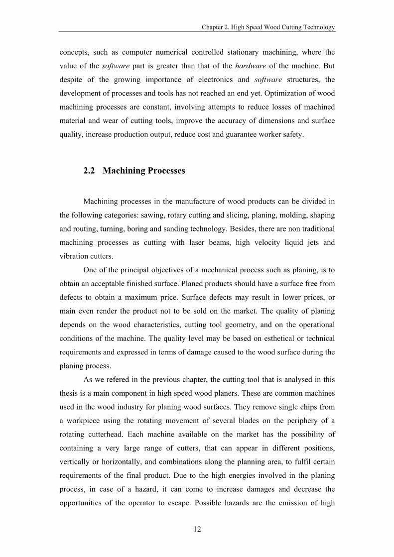
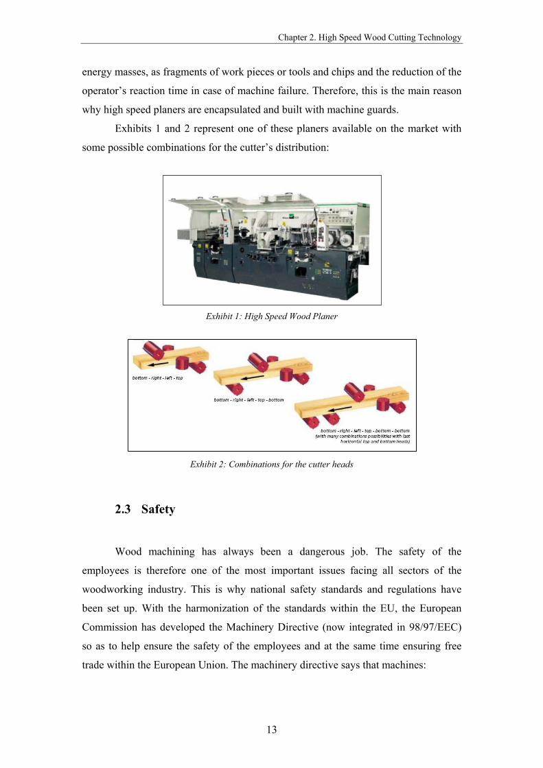
Exhibits 1 and 2 represent one of these planers available on the market with
some possible combinations for the cutter’s distribution:
Exhibit 1: High Speed Wood Planer
Exhibit 2: Combinations for the cutter heads
2.3 Safety
Wood machining has always been a dangerous job. The safety of the
employees is therefore one of the most important issues facing all sectors of the
woodworking industry. This is why national safety standards and regulations have
been set up. With the harmonization of the standards within the EU, the European
Commission has developed the Machinery Directive (now integrated in 98/97/EEC)
so as to help ensure the safety of the employees and at the same time ensuring free
trade within the European Union. The machinery directive says that machines:

Chapter 2. High Speed Wood Cutting Technology
14
• Must satisfy wide-ranging health and safety requirements, for example on
construction, moving parts, and stability;
• Must, in some cases, be subjected to type examination by an approved body;
• Must carry the CE mark and other specific information.
Each member state has integrated the Machinery Directive into its own laws
within a certain adoption time (1995). The Machinery Directive is supported by a
series of European Standards such as:
• EN 847 Tools for woodworking: Safety requirements – Part 1, 2 and 3
• EN 860 Safety of woodworking: One side thickness planing machines
• EN 861 Safety of woodworking: Surface planing and thickness machines
• EN 940 Safety of woodworking: Combined woodworking machines and
further standards
The requirements of these standards concern designers, manufactures,
suppliers and importers of tools for woodworking. These standards also include
information witch the manufacturer shall provide to the user.
Concerning the objectives of our project, standard EN 847/1 assumes a major
importance, describing requirements and methods for the elimination or reduction of
hazards arising from the design of wood working tools.
2.4 Certification
The experimental tests introduced in the first chapter as making part of the
European security standards for rotating cutting tools, have to be performed in
specific laboratories, with appropriate testing machines for such a severe solicitation.
The standard EN 847 specifies all the procedures to be adopted when running one of
these tests.
BG-PRÜFZERT in Germany is one institution composed by several testing
laboratories, which are able to test and certify several types of machines according to
the standards.

Chapter 2. High Speed Wood Cutting Technology
15
This technical institution has already tested and certified the first wood cutting
tool developed by Verktygs Larsson AB, with 16 blades, 203mm of external diameter
and 168mm of total blade’s length with a shaft diameter of 60mm. The centrifugal test
in a vacuum chamber consisted in raising the cutter speed until 7500 rpm (normal
speed of use) on a first stage and afterwards until 11250rpm. This value was
determined taking into account a 1,5 security coefficient established in the EN 847
standard. When the test reaches the end, a measure of the displacements in several
points of the cutter is performed.

Chapter 3. Cutting Tool Prototype
16
CUTTING TOOL PROTOTYPE
After introducing some theoretical knowledge in the previous chapter, we are
now ready to understand the mechanism and specifications of the cutting tool.
3.1 Mechanism presentation
In a general way, we can say the cutter is composed by some groups of
components that are uniformly distributed in the main body. Each one of these groups
has one screw, two different wedges, the tightening and the support wedge, one blade
and finally four support pins.
As we can see in the exhibit 3, in each cavity of the cylinder there is a ramp in
the back side. This ramp will contact with another one, with the same slope, that
exists in the correspondent supporting wedge. The main function of these ramps is to
hold the effect of the tightening force that will be applied in the screw, communicated
to the support wedge by the tightening wedge.
Finally, the tool contains the pins that fit the blade in the working position. We
should notice that the main part of the centrifugal force acting on the blade is balanced
by the friction forces on its contact surfaces. Therefore, the function of the pins cannot
be considered as structural.

Chapter 3. Cutting Tool Prototype
17
Exhibit3: Back side ramps in the main body
In order to perform the attachment of the planer cutter to the machine shaft is
used hydraulic pressure applied to the bushes that are incorporated in the interior of
the main cylinder.
Before being applied to a planer machine, the tool has to be balanced, in order
to achieve the best mass distribution. The influence of this balance is specially noticed
when rotating at lower speeds.
Exhibit 4: Components of the cutter

Chapter 3. Cutting Tool Prototype
18
To achieve a better understanding of this complex mechanism and the physical
interactions between all components, the main assembling procedures of the cutting
tool are presented in the following points:
1. Weight all the components of the same type (blades, wedges, screws)
and mark them with the respective values. Pairs with the most approximate value
should be placed in diametrical opposite positions in order to guarantee the best
balance of the tool;
2. Mount the blades, fitting them correctly with the pins, starting the
assembly in the track marked with number 1;
Exhibit 5: Blade assembling
3. Slide the big wedge along the number 1 track until it stops in the
bottom contacting with the ramp. Complete the round distribution;
4. Place the screws in the respective holes, rotating them 3 to 4 times;
Exhibit 6: Screws assembling
5. Insert the tightening wedge in its track and in the big wedge;
Chapter 3. Cutting Tool Prototype
19
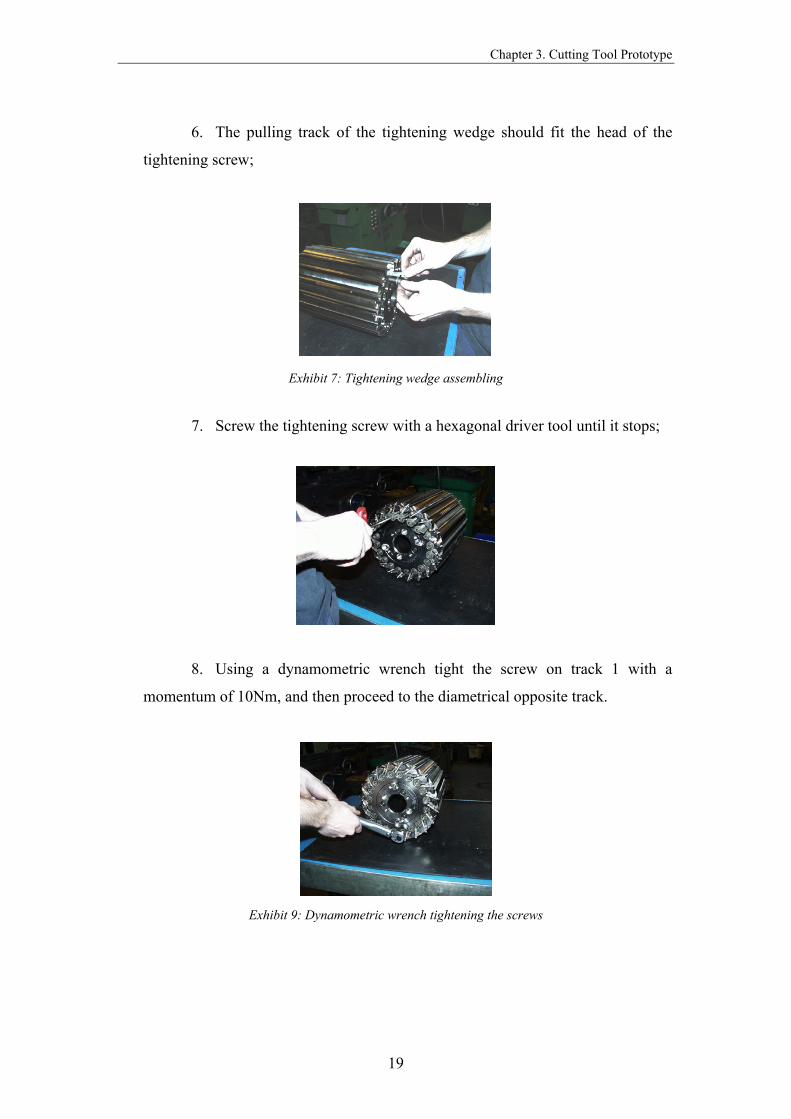
6. The pulling track of the tightening wedge should fit the head of the
tightening screw;
Exhibit 7: Tightening wedge assembling
7. Screw the tightening screw with a hexagonal driver tool until it stops;
Exhibit 8: Tightening the screws
8. Using a dynamometric wrench tight the screw on track 1 with a
momentum of 10Nm, and then proceed to the diametrical opposite track.
Exhibit 9: Dynamometric wrench tightening the screws

Chapter 3. Cutting Tool Prototype
20
9. Proceed tightening the screws with 22Nm of momentum, starting again
in track 1, and proceeding to the diametric opposite track.
3.2 Specifications
Our study will be pointed to a specific geometry, in order to try to understand
the variables that are affecting its behaviour, and also to know how important they are
to the mechanism function. This geometry has 20 blades uniformly distributed around
the cylinder with 220mm of external diameter and 45mm of internal diameter. The
length of the main body is 270mm.
There are different dimensions available for this tool [Table 1], to suit the
needs of the customers, obtained by changing some design parameters. The tool can
include a maximum of 30 blades covering a diameter of 300mm with a total length of
340mm. However, the main design is common to all of them. The geometries that
were analysed in this project appear as shadowed.
Øexternal [mm]
Total length[mm]
Øshaft [mm]
N. Blades [mm]
180 120 45 12 180 120 50 12 203 170 45 16 203 245 45 16 203 270 45 16 203 170 50 16 203 170 50 16 203 270 50 16 220 170 45 20 220 245 45 20 220 270 45 20 220 170 50 20 220 245 50 20 220 270 50 20 250 170 45 24 250 245 45 24 250 270 45 24 250 170 50 24 250 245 50 24 250 270 50 24 250 245 60 20 300 340 80 30
Table 1: Cutting tool available dimensions
Chapter 3. Cutting Tool Prototype
21
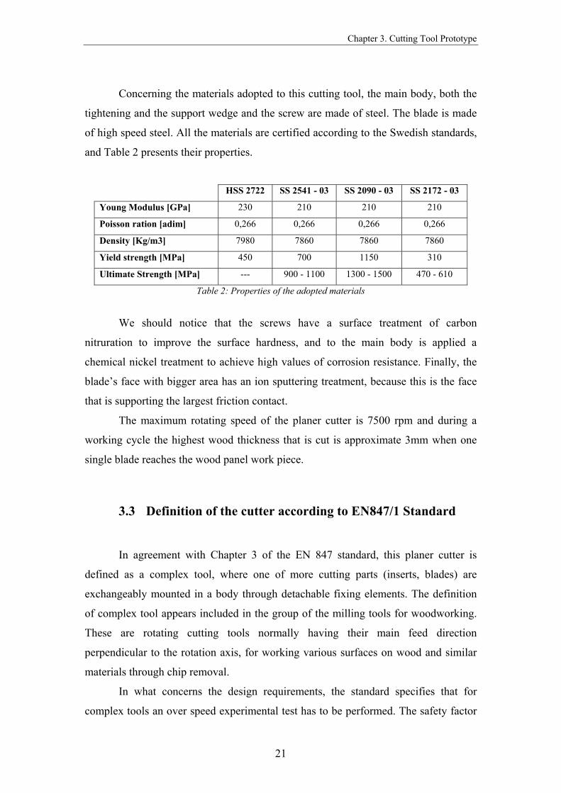
Concerning the materials adopted to this cutting tool, the main body, both the
tightening and the support wedge and the screw are made of steel. The blade is made
of high speed steel. All the materials are certified according to the Swedish standards,
and Table 2 presents their properties.
HSS 2722 SS 2541 - 03 SS 2090 - 03 SS 2172 - 03
Young Modulus [GPa] 230 210 210 210
Poisson ration [adim] 0,266 0,266 0,266 0,266
Density [Kg/m3] 7980 7860 7860 7860
Yield strength [MPa] 450 700 1150 310
Ultimate Strength [MPa] --- 900 - 1100 1300 - 1500 470 - 610
Table 2: Properties of the adopted materials
We should notice that the screws have a surface treatment of carbon
nitruration to improve the surface hardness, and to the main body is applied a
chemical nickel treatment to achieve high values of corrosion resistance. Finally, the
blade’s face with bigger area has an ion sputtering treatment, because this is the face
that is supporting the largest friction contact.
The maximum rotating speed of the planer cutter is 7500 rpm and during a
working cycle the highest wood thickness that is cut is approximate 3mm when one
single blade reaches the wood panel work piece.
3.3 Definition of the cutter according to EN847/1 Standard
In agreement with Chapter 3 of the EN 847 standard, this planer cutter is
defined as a complex tool, where one of more cutting parts (inserts, blades) are
exchangeably mounted in a body through detachable fixing elements. The definition
of complex tool appears included in the group of the milling tools for woodworking.
These are rotating cutting tools normally having their main feed direction
perpendicular to the rotation axis, for working various surfaces on wood and similar
materials through chip removal.
In what concerns the design requirements, the standard specifies that for
complex tools an over speed experimental test has to be performed. The safety factor

Chapter 3. Cutting Tool Prototype
22
of 1,5 should be applied to the maximum rotational speed of the tool, establishing a
testing of 11250 rpm in the case of our cutter. During the test, the displacements
should not be greater than 0,15mm and their measurement has to be performed with
the tool stopped, after rotating it for 1 minute at the test speed.
The standard allows one deviation from the specifications given above in the
case of milling tools with centrifugal wedges. In this type of tools, if the calculation is
performed to the most unfavourable tolerances and for the test speed, and if the
obtained stresses are in the elastic range of the materials, then greater displacements
are permitted. But these displacements of the centrifugal wedges shall not adversely
influence the function and behaviour of the tool.

Chapter 4. Finite Element Method
23
FINITE ELEMENT METHOD
This chapter presents some introductory fundaments of finite element theory
in addiction with some considerations about finite element softwares.
4.1 Introduction
Since early 1980s Finite Element Method and the softwares based on it, were
recognised as powerful tools solving some engineering problems. The affordability
and versatility of Finite Element (FE) softwares has helped to spread its popularity.
Nowadays, solvers are much user friendly and the task of applying them has
become easier. However, this has also resulted in the wrong use of these softwares by
people who are not familiar with the fundamental concepts of FE theory. That is to
say that a great amount of engineering judgement is also needed.
4.2 Fundaments
Most numerical techniques in continuum mechanics are based on the principle
that it is possible to derive some equations and relationships that accurately describe
the behaviour of a small part of the body.
Chapter 4. Finite Element Method
24
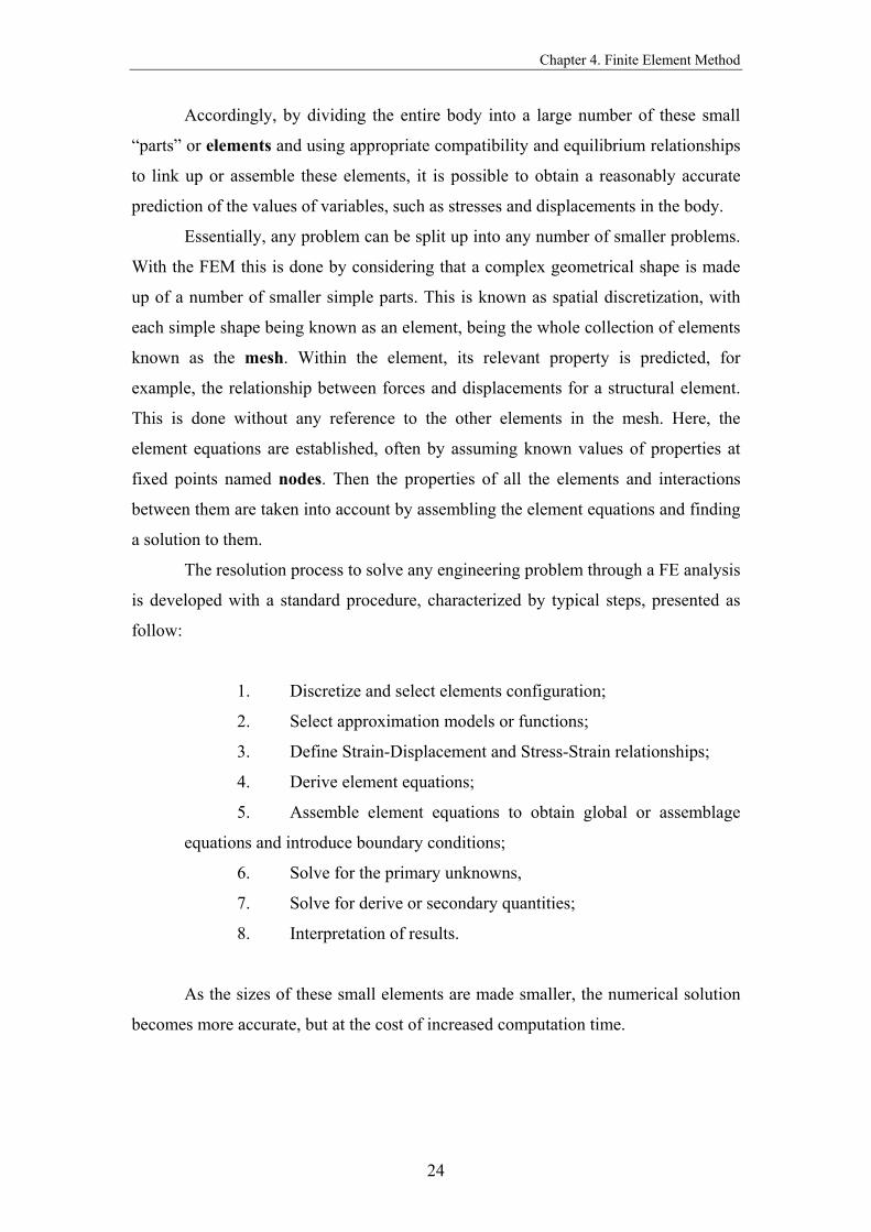
Accordingly, by dividing the entire body into a large number of these small
“parts” or elements and using appropriate compatibility and equilibrium relationships
to link up or assemble these elements, it is possible to obtain a reasonably accurate
prediction of the values of variables, such as stresses and displacements in the body.
Essentially, any problem can be split up into any number of smaller problems.
With the FEM this is done by considering that a complex geometrical shape is made
up of a number of smaller simple parts. This is known as spatial discretization, with
each simple shape being known as an element, being the whole collection of elements
known as the mesh. Within the element, its relevant property is predicted, for
example, the relationship between forces and displacements for a structural element.
This is done without any reference to the other elements in the mesh. Here, the
element equations are established, often by assuming known values of properties at
fixed points named nodes. Then the properties of all the elements and interactions
between them are taken into account by assembling the element equations and finding
a solution to them.
The resolution process to solve any engineering problem through a FE analysis
is developed with a standard procedure, characterized by typical steps, presented as
follow:
1. Discretize and select elements configuration;
2. Select approximation models or functions;
3. Define Strain-Displacement and Stress-Strain relationships;
4. Derive element equations;
5. Assemble element equations to obtain global or assemblage
equations and introduce boundary conditions;
6. Solve for the primary unknowns,
7. Solve for derive or secondary quantities;
8. Interpretation of results.
As the sizes of these small elements are made smaller, the numerical solution
becomes more accurate, but at the cost of increased computation time.
Chapter 4. Finite Element Method
25
4.3 Considerations about Finite Element Softwares
The FE solvers market range is divided in two main categories: the pure FE
and CAD/CAE softwares. Considering the complexity of the analysis, the first option
appears at the beginning as the more accurate. But, the second type of softwares,
combining Computer Aided Design and Computer Aided Engineering tools, allows
users to decrease design and analysis times.
CATIA is a widely known software that is included into the second category.
The educational version available during this project at Linköping University includes
a toolbox with instruments to perform static analysis using a FE code.
Chapter 5. Modeling
26
MODELING
In this chapter the analysis assumptions are introduced, as well as all the
explanation about the adopted models, considering the elements, meshes and the
applied loads.
5.1 Introduction
The concept of modelling is based on a main line of creating an approximation
of a real problem, considering always some simplifications. This is a primary need
because complex models are depending on high calculation times.
During our work of analysing the cutting tool we followed this path, passing
through several models, to achieve the primary target.
The following part of this chapter presents all the models carried out in
CATIA environment since the beginning, introducing all simplifications that were
taken in account and justifying them with the respective assumptions.
5.2 Static analysis
To achieve the desired answers to our problem, we adopted a static analysis of
the tool, being this, the first simplification that was made. The real problem is

Chapter 5. Modeling
27
typically dynamic, however, it can be approximated by a static process without being
too distant from the reality.
The effect of the rotation speed was substituted by one equivalent centrifugal
force applied to all bodies. With this assumption, the effect of the movement
conditions is translated by forces and constraints.
Considering the geometric axis system, we can say that this situation is
equivalent to someone being placed in one of the lateral faces of the main body. If we
imagine our selves in this position, with the same rotating movement as the cylinder,
we can visualize this one has being stopped, because we are rotating with same
velocity and in the same direction, with the possibility of just observing its
displacements.
Considering the refered evolution from the dynamic to the static state, the
interior face of the main cylinder where the shaft fits had to be necessarily clamped.
In operation, our tool is subjected to static and dynamic loads. The structural
load generated by centrifugal forces becomes dominant over the forces resulting from
the cutting process. Concerning the dynamic proportions of the load, the tool is
subjected to forces resulting from the cutting process, introducing pulsating stresses
and cyclic centrifugal forces due to acceleration and desaccelaration. The centrifugal
force acts as the main load both on the tool body and on the cutting element, while the
cutting forces counteract the effect of the centrifugal forces on the cutting element.
However, the most critical situation is when the tool is freely rotating without
being in contact with the work piece, since there is no energy dissipation through the
cutting act. It happens for instance in the initial stage. Therefore, we have considered
a static model with centrifugal solicitations at a constant operating speed.
5.3 Evolution on the geometry of the model
As we announced in the beginning of this chapter, due to the complexity of the
involved mechanism, simplifications related with the geometry of the model had to be
made. The first idea of building one model similar to the real tool, with the 20 tracks
filled with the components, was immediately left, considering that just the assembly
procedure would be extremely complicated. Besides, the computation task would be
impossible, with the need of super workstations. Therefore, we made an evolution to
Chapter 5. Modeling
28
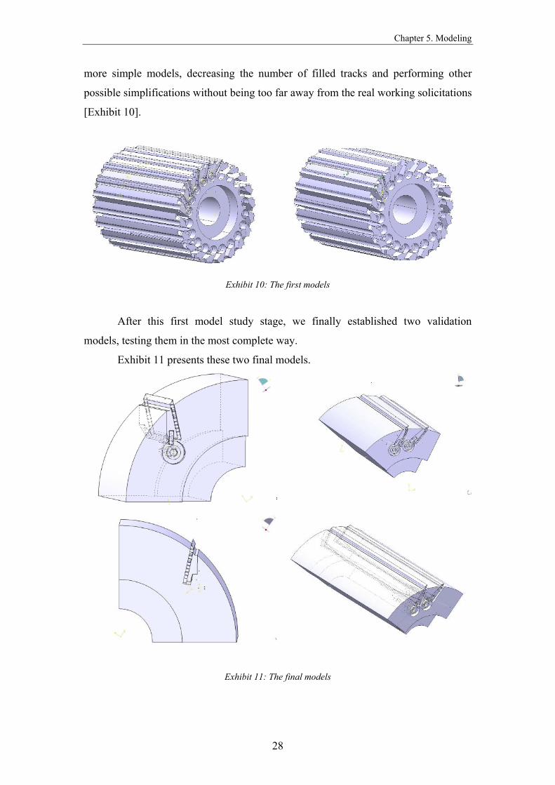
more simple models, decreasing the number of filled tracks and performing other
possible simplifications without being too far away from the real working solicitations
[Exhibit 10].
Exhibit 10: The first models
After this first model study stage, we finally established two validation
models, testing them in the most complete way.
Exhibit 11 presents these two final models.
Exhibit 11: The final models

Chapter 5. Modeling
29
With the second model, we intended to study how the existence or not of
components in adjacent tracks would affect the displacements and stresses.
In both models, the lateral surfaces were clamped, in order to simulate the
presence of the main body’s volume that was not considered.
The refered bushes that attach the planer cutter to the rotating shaft were not
included in the model due to the fact that their function is not structural, having no
influence to the safety analysis that is intended to be done.
In accordance with these final models, analyses were made to achieve the final
output of determining the maximum displacements and stresses, in order to guarantee
that these are in the range established by the standard. Both models were applied to
the first geometry refered in Chapter 3. Considering the geometry with a length of
340mm and an external diameter of 300mm, the biggest, only the first model was
used.
A final comment has to be made regarding the quality of the parts designed
with CATIA to build the assembly. Based on the technical drawings created by the
company, all the components were designed with all the details and with an extreme
accuracy concerning the dimensions involved.
5.4 Assembly constraints
Using CATIA mechanical design toolbox, we were able to create all the
components separately as a part, namely the tightening wedge, the support wedge, the
screw and the blade, as well as the main cylindrical body. After that, an assembly was
made to create each model. Independently on the model, the positioning constraint’s
type used to perform each assembly was surface contact, which can be applied
between two planar faces.
5.5 Analysis connections
Once the geometric assembly positioning constraints are defined at the product
level, the physical nature of the connections has to be defined. Considering the
Chapter 5. Modeling
30
problem itself and the characteristics of each type of connection available, we used
four types, namely slider, contact, fastened and bolt tightening.
The slider connection property can be described has a link between two bodies
which are constrained to move together in the local normal direction at their common
boundary, and will behave as if they were allowed to slide relative to each other in the
local tangential plane. Meanwhile, a contact connection is the link between two part
bodies which are prevented from inter-penetrating at their common boundary, and
will behave as if they were allowed to move arbitrarily relative to each other as long
as they do not come into contact within a user-specified normal clearance. When they
come into contact, they can still separate or slide relative to each other in the
tangential plane, but they cannot reduce their relative normal clearance.
On the other hand, a fastened connection is the link between two bodies which
are fastened together at their common boundary, and will behave as if they were a
single body. From a finite element model viewpoint, this is equivalent to the situation
where the corresponding nodes of two compatible meshes are merged together.
Finally, a bolt tightening connection takes into account pre-tension in bolt-
tightened assemblies. The computation is carried out according to a two-step
approach. In the first step of the computation, the model is submitted to tension forces
relative to bolt tightening by applying opposite forces on the bolt thread and on the
support tapping, respectively. Then, in the second step, the relative displacement of
these two surfaces (obtained in the first step) is imposed while the model is submitted
to user loads. During these two steps, the bolt and the support displacements are
linked in the direction normal to the bolt axis.
Since bodies can be meshed independently, all the presented connections are
able to deal with incompatible meshes.
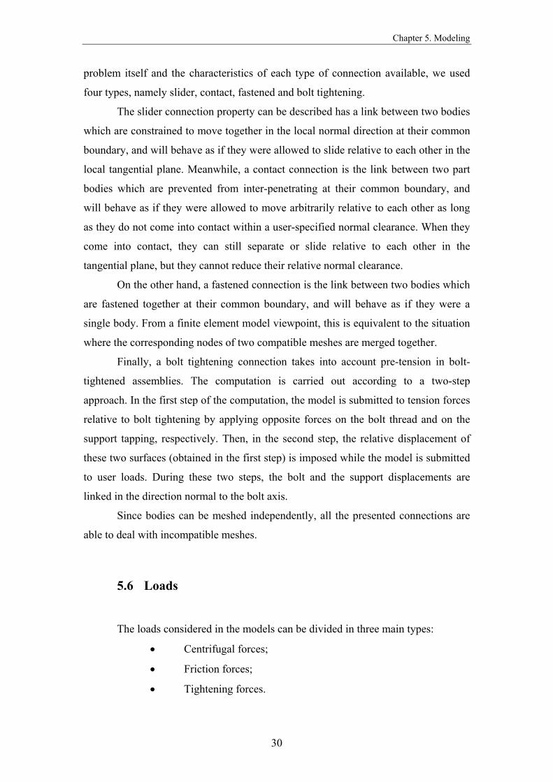
5.6 Loads
The loads considered in the models can be divided in three main types:
• Centrifugal forces;
• Friction forces;
• Tightening forces.

Chapter 5. Modeling
31
The assumptions and considerations made for each type are presented in
following points.
5.6.1 Centrifugal Forces
The centrifugal force acts as the main load in the tool body and also in the rest
of the components. Theoretically, this force can be calculated according with the
formula:
lcentrifugalcentrifuga a mF ×=
Attending to the definition of centrifugal acceleration and also to the relation
between the tangential and rotational speeds,
c.g.
2
lcentrifugarv a =
c.g.rv ×= ω
it is possible to rewrite the previous expression:
2
c.g. lcentrifuga r m F ω××=
The values of the masses of the main components included in the cutter for the
two geometries studied are presented in the Table 3.
1st Geometry Length = 270mm Øext = 220mm
2nd Geometry Length = 340mm Øext = 300mm
Main body 51 [Kg] 135 [Kg] Support wedge 0,346 [Kg] 0,440 [Kg] Blade 0,206 [Kg] 0,261 [Kg]
Table 3: Masses of some components

Chapter 5. Modeling
32
Using the previous values and considering the centre of gravity radius of each
component provided by the software, it was possible to determine the centrifugal
forces.
1st Geometry 2nd Geometry 7500 rpm 11250 rpm 7500rpm 11250rpm Support wedge 20728,5N 46639,1N 28320,8N 63721,8N Blade 12383,9N 27863,9N 16691,7N 37556,2N
Table4: Centrifugal forces acting on the support wedge and on the blade
Besides the general increase in the centrifugal forces, higher normal reactions
are obtained because of the function of the support wedge. Therefore, higher values of
maximum static friction forces are available to perform an opposition to the trend that
the blade has to fly away.
Analysing these results for first geometry, we should notice that when raising
the speed from 7500rpm to 11250rpm, there is an increase in the centrifugal force of
the blade of 15480N, while the support wedge has an increase of 25911N.
To the second geometry, the increase in the centrifugal force of the blade is
20864N, while in the support edge is 35401N.
We can conclude that the increase of the centrifugal force associated to the
support wedge, giving normal reactions with more magnitude, is higher than the
increase in the blade. This can be a possible explanation to a curious phenomenon
verified during the experimental test performed in Germany, where the measured
displacements at 11250rpm were lower than at 7500rpm.
5.6.2 Friction Forces
Regarding the final objective of this tool, the friction forces can be considered
the most important load acting on the mechanism. They have a fundamental role in
the behaviour of the cutter at high speed, and therefore, the model has to be specially
accurate concerning this loads.
When the all mechanism is set up, friction forces exist between the main faces
of the following components:
Chapter 5. Modeling
33
• Blade and cylinder;
• Blade and support wedge;
• Support wedge and cylinder;
• Tightening wedge and support wedge;
• Tightening wedge and cylinder.
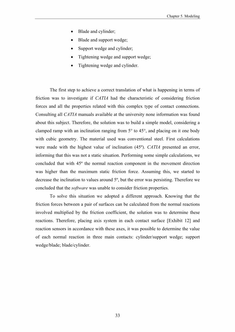
The first step to achieve a correct translation of what is happening in terms of
friction was to investigate if CATIA had the characteristic of considering friction
forces and all the properties related with this complex type of contact connections.
Consulting all CATIA manuals available at the university none information was found
about this subject. Therefore, the solution was to build a simple model, considering a
clamped ramp with an inclination ranging from 5° to 45°, and placing on it one body
with cubic geometry. The material used was conventional steel. First calculations
were made with the highest value of inclination (45º). CATIA presented an error,
informing that this was not a static situation. Performing some simple calculations, we
concluded that with 45º the normal reaction component in the movement direction
was higher than the maximum static friction force. Assuming this, we started to
decrease the inclination to values around 5º, but the error was persisting. Therefore we
concluded that the software was unable to consider friction properties.
To solve this situation we adopted a different approach. Knowing that the
friction forces between a pair of surfaces can be calculated from the normal reactions
involved multiplied by the friction coefficient, the solution was to determine these
reactions. Therefore, placing axis system in each contact surface [Exhibit 12] and
reaction sensors in accordance with these axes, it was possible to determine the value
of each normal reaction in three main contacts: cylinder/support wedge; support
wedge/blade; blade/cylinder.

Chapter 5. Modeling
34
Exhibit 12: Axis systems used to apply the sensors
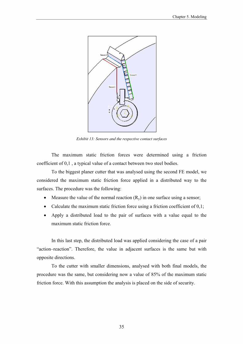
Table5 presents the values of the normal reactions determined using the
refered sensors while exhibit 13 shows the surfaces where they were placed.
1st Geometry
Øext = 220mm
Length = 270mm
2nd Geometry
Øext = 300mm
Length = 340mm
Model 1 Model 2 Model 1
Sensor 1 192390N 239381N 355512N
Sensor 2 161990N 209561N 308283N
Sensor 3 148762N 142692N 281601N
Sensor 4 - 215729N -
Sensor 5 - 185380N -
Sensor 6 - 172150N -
Table 5: Normal reactions (Ry) in the contact surfaces
Obviously, model number 2 includes sensors in both filled tracks, numbered
from 4 to 6.
Chapter 5. Modeling
35
Exhibit 13: Sensors and the respective contact surfaces
The maximum static friction forces were determined using a friction
coefficient of 0,1 , a typical value of a contact between two steel bodies.
To the biggest planer cutter that was analysed using the second FE model, we
considered the maximum static friction force applied in a distributed way to the
surfaces. The procedure was the following:
• Measure the value of the normal reaction (Ry) in one surface using a sensor;
• Calculate the maximum static friction force using a friction coefficient of 0,1;
• Apply a distributed load to the pair of surfaces with a value equal to the
maximum static friction force.
In this last step, the distributed load was applied considering the case of a pair
“action–reaction”. Therefore, the value in adjacent surfaces is the same but with
opposite directions.
To the cutter with smaller dimensions, analysed with both final models, the
procedure was the same, but considering now a value of 85% of the maximum static
friction force. With this assumption the analysis is placed on the side of security.

Chapter 5. Modeling
36
Exhibit 14: The distributed friction forces
5.6.3 Tightening Forces
Attending of the assembling information provided by Verktygs Larsson AB,
the value of the momentum used to tighten the screws was 22 N.m. In order to
establish the above refered bolt tightening connection property, this momentum had to
be converted to a pre-tension force.
This conversion can be made using the following formula:
F: Pre-Tension Force [N]
T: Tightening momentum [N.m]
α: Flank angle [rad]
dm: Nominal diameter [m]
µ: Friction coefficient [adim]
l: Pitch [m ]
Since the screws used in the cutter have a metric thread M10, the following
values are standard and specified:
Pitch: 31,42 [mm] 0,03142 [m]
Nominal diameter: 10,00 [mm] 0,010 [m]
Flank angle: 15,00 [º] 0,262 [rad]
+
=αµπαµπ
sec l sec l -d
d2TF m
m

Chapter 5. Modeling
37
Substituting the previous values on the refered formula, a pre-tension force of
2008 N is obtained.
5.7 Element and Mesh Properties
Elements:
In all the models that were considered during the development of this thesis,
the linear tetrahedron element [Exhibit 15] was used as standard for all the three-
dimensional meshes. It is a four nodes isoparametric solid element with the following
properties:
Exhibit 15: Tetrahedron element
Meshes:
As it was refered in previous chapters, the planer cutter studied in this thesis
presents a complex geometry. This complexity comes from several design details
Type: solid element
Physical property: solid
Mesh connectivity: linear tetrahedron
Number of nodes: 4
Degrees of freedom: 6
Type of behaviour: elastic

Chapter 5. Modeling
38
included in the main body and in the components. For example, measures can range
from 3mm in the contact of the blades to the pins until 340mm in the main body.
These variations of measures increase not only the calculation times, but
mainly the probability of errors associated with the finite element analysis due to the
appearance of singularities.
Therefore, a precise mesh refinement had to be made for example in the pins,
ramps, small contact surfaces and other places that were inducing errors to the
analysis.

Chapter 6. Results
39
RESULTS
This chapter will present the results of the analysis obtained during the project.
It is divided in two main parts, in accordance with the studied geometries, including
the meshes, displacements, stresses and estimated local errors. It was an option to
include in this chapter only the most important output exhibits, placing the rest of the
figures in an appendix.
6.1 Model with one blade applied to the first geometry
Attending on the obtained results for the deformed mesh, they comproved the
deformation idea that we expected to be verified during the working conditions. In all
components the displacements were minimum.
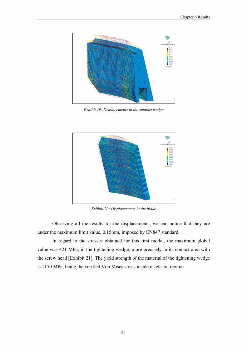
The blade and the support wedge showed a slight bending behaviour, due to
their fixing conditions [Exhibits 19 and 20]. The maximum displacement observed in
the blade happens in the middle section, with a value of 0,0948mm.
Concerning the support wedge, the maximum value is also verified in the
middle of this component, being equal to 0,141mm. In the tightening wedge and in the
screw, both maximum displacements are under the previous values.

Chapter 6.Results
40
Exhibit 16: Global mesh
Exhibit 17: Deformed mesh
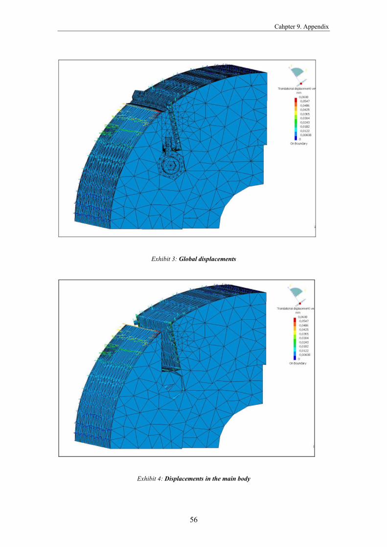
The displacements on the main body are maximum in the influence side of the
support wedge, reaching 0.0608mm [Exhibit 18].
Exhibit 18: Displacements in the main body
Chapter 6.Results
41
Exhibit 19: Displacements in the support wedge
Exhibit 20: Displacements in the blade
Observing all the results for the displacements, we can notice that they are
under the maximum limit value, 0,15mm, imposed by EN847 standard.
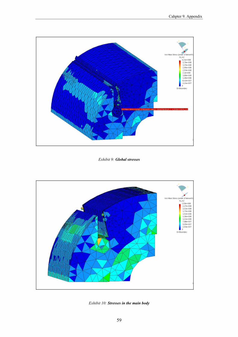
In regard to the stresses obtained for this first model, the maximum global
value was 421 MPa, in the tightening wedge, more precisely in its contact area with
the screw head [Exhibit 21]. The yield strength of the material of the tightening wedge
is 1150 MPa, being the verified Von Mises stress inside its elastic regime.
Chapter 6.Results
42
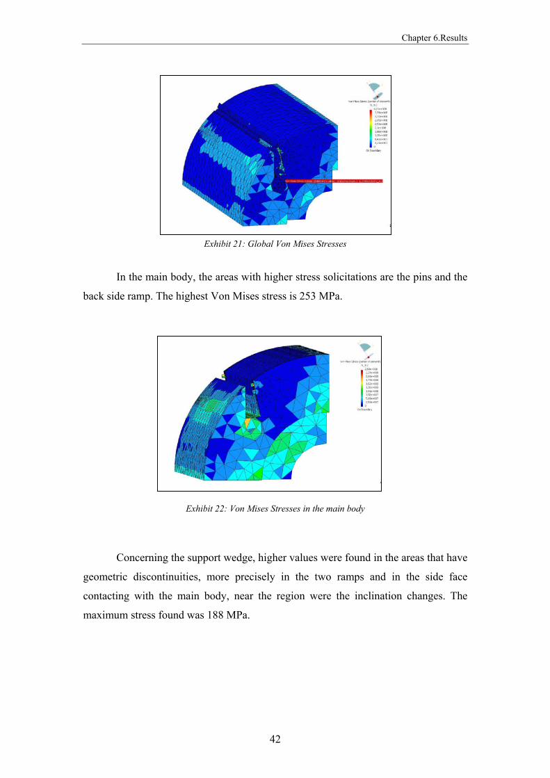
Exhibit 21: Global Von Mises Stresses
In the main body, the areas with higher stress solicitations are the pins and the
back side ramp. The highest Von Mises stress is 253 MPa.
Exhibit 22: Von Mises Stresses in the main body
Concerning the support wedge, higher values were found in the areas that have
geometric discontinuities, more precisely in the two ramps and in the side face
contacting with the main body, near the region were the inclination changes. The
maximum stress found was 188 MPa.
Chapter 6.Results
43
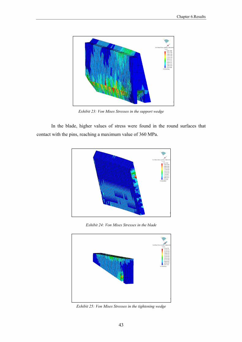
Exhibit 23: Von Mises Stresses in the support wedge
In the blade, higher values of stress were found in the round surfaces that
contact with the pins, reaching a maximum value of 360 MPa.
Exhibit 24: Von Mises Stresses in the blade
Exhibit 25: Von Mises Stresses in the tightening wedge

Chapter 6.Results
44
Therefore, we can resume that for all components, the verified stresses are
inside the elastic regime, with no existing possibility of plasticity.
In this analysis with the first FE model adopted, the highest estimated local error
(0,00572 J) was observed in the main body area where the screw head fits.
Exhibit 26: Estimated local errors in the main body
6.2 Model with two blades applied to the first geometry
Introducing this second model, it was possible to verify the initial idea of
making a comparison between both models displacements, mainly because the
existence of more than one blade would be a weight factor. Due to higher values of
normal reactions, displacements in the middle of the blade were lower, comparing the
ones that were obtained with the first model. The maximum value was 0,0714mm
[Exhibit 31].
Exhibit 27: Global mesh
Chapter 6.Results
45
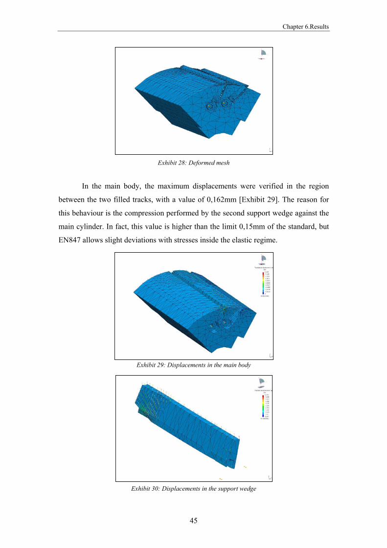
Exhibit 28: Deformed mesh
In the main body, the maximum displacements were verified in the region
between the two filled tracks, with a value of 0,162mm [Exhibit 29]. The reason for
this behaviour is the compression performed by the second support wedge against the
main cylinder. In fact, this value is higher than the limit 0,15mm of the standard, but
EN847 allows slight deviations with stresses inside the elastic regime.
Exhibit 29: Displacements in the main body
Exhibit 30: Displacements in the support wedge
Chapter 6.Results
46
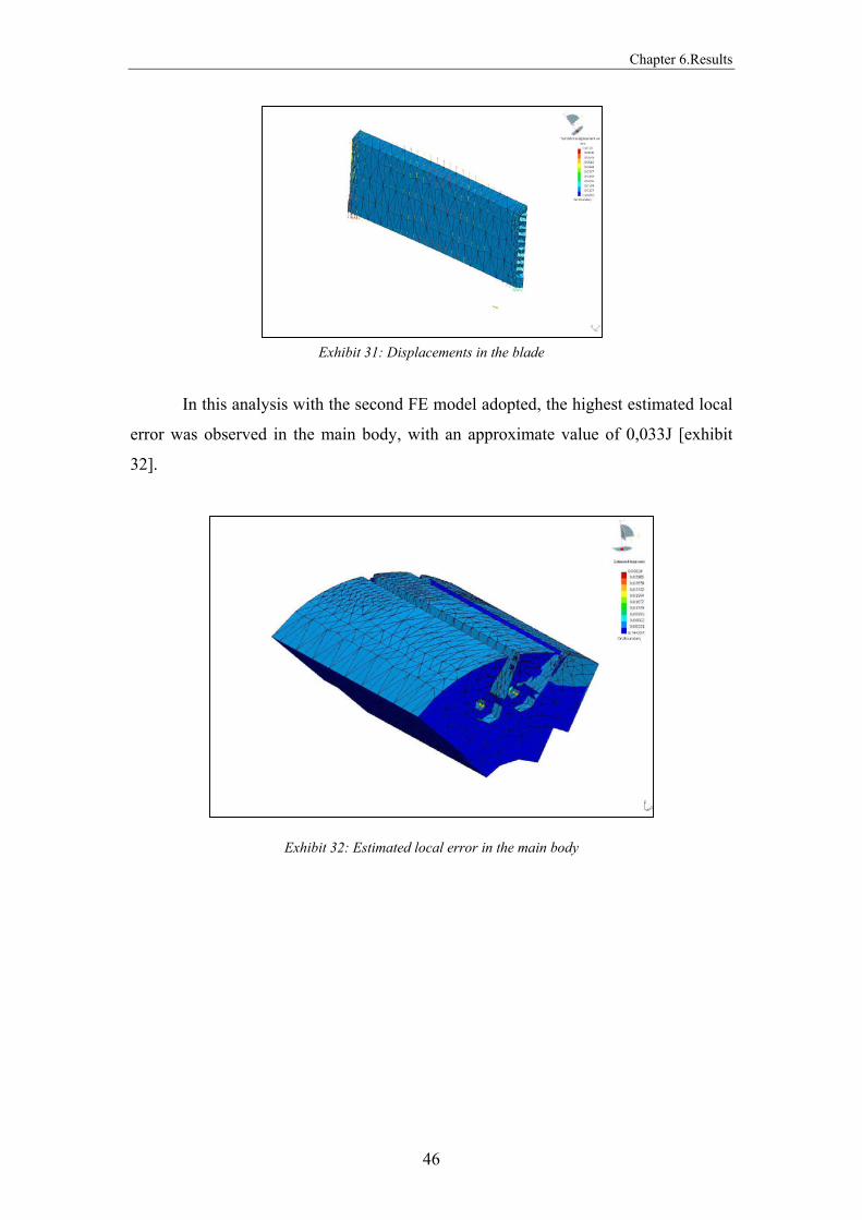
Exhibit 31: Displacements in the blade
In this analysis with the second FE model adopted, the highest estimated local
error was observed in the main body, with an approximate value of 0,033J [exhibit
32].
Exhibit 32: Estimated local error in the main body

Chapter 6.Results
47
6.3 Model with one blade applied to the second geometry
The analysis of the cutter with the highest dimensions was performed using the
first model, since that a conclusion regarding the comparison between both was
already been made with the smallest cutter.
Therefore, a maximum displacement of 0,103mm was observed in the main
body, being under the limit range of the standard [Exhibit 34].
Exhibit 33: Deformed mesh
Exhibit 34: Displacements in the main body
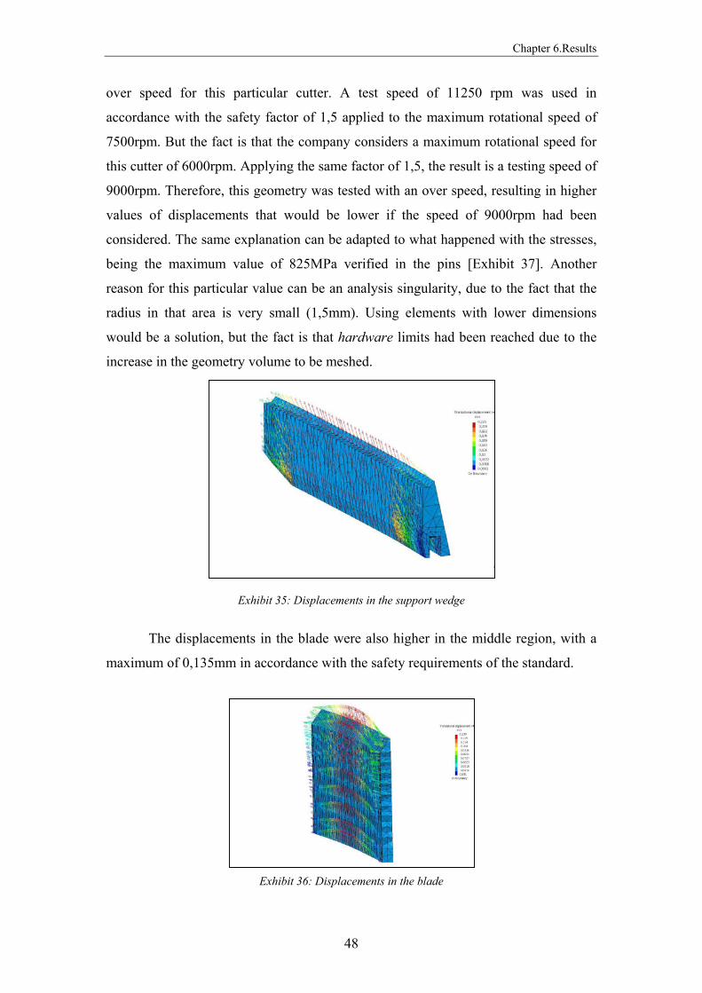
The support wedge was the component with the highest displacements, with a
maximum value of 0,225mm [Exhibit 35]. A possible explanation for this value that is
slight over the limit of the standard, is the fact that this analysis was performed at an
Chapter 6.Results
48
over speed for this particular cutter. A test speed of 11250 rpm was used in
accordance with the safety factor of 1,5 applied to the maximum rotational speed of
7500rpm. But the fact is that the company considers a maximum rotational speed for
this cutter of 6000rpm. Applying the same factor of 1,5, the result is a testing speed of
9000rpm. Therefore, this geometry was tested with an over speed, resulting in higher
values of displacements that would be lower if the speed of 9000rpm had been
considered. The same explanation can be adapted to what happened with the stresses,
being the maximum value of 825MPa verified in the pins [Exhibit 37]. Another
reason for this particular value can be an analysis singularity, due to the fact that the
radius in that area is very small (1,5mm). Using elements with lower dimensions
would be a solution, but the fact is that hardware limits had been reached due to the
increase in the geometry volume to be meshed.
Exhibit 35: Displacements in the support wedge
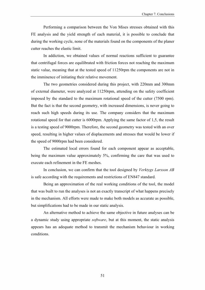
The displacements in the blade were also higher in the middle region, with a
maximum of 0,135mm in accordance with the safety requirements of the standard.
Exhibit 36: Displacements in the blade

Chapter 6.Results
49
Exhibit 37: Global stresses
In this analysis, the highest estimated local error was observed in the main body, with
an approximate value of 0,01 J [exhibit 38].
Exhibit 38: Estimated local error in the main body

Chapter 7. Conclusions
50
CONCLUSIONS
To achieve the final objective of verifying the safety of the wood planer cutter
developed by Verktygs Larsson AB, EN847 standard was analyzed carefully, with
special attention to the requirements included. As it was explained, the standard
presents limit values for the displacements found on the different components of the
tool, being the highest admitted value equal to 0,15mm. The standard allows one
deviation, admitting higher displacements if the obtained stresses are in the elastic
range of the materials without influencing the working behaviour of the mechanism.
Before presenting the conclusions of this project, a main difference between
the standard and the analysis we performed has to be introduced. The displacements
referenced in EN847 are measured with the tool stopped, while our displacements and
stresses were obtained applying equivalent loads to the model we developed.
Therefore, a direct comparison between the standard specifications and our results is
possible to be made but taking into account that the displacements in each case don’t
have the same background. We can say that in our analysis we are placed side by side
with security, due to the fact that the results were obtained by performing a direct
relation with the applied loads.
Attending on the values presented both on the results chapter and in the
following appendix, a conclusion can be immediately made. The displacements for
the components of the planer cutter, considering both geometries analyzed, are inside
the security range established by the standard, not reaching the maximum value of
0,15mm.
Chapter 7. Conclusions
51
Performing a comparison between the Von Mises stresses obtained with this
FE analysis and the yield strength of each material, it is possible to conclude that
during the working cycle, none of the materials found on the components of the planer
cutter reaches the elastic limit.
In addiction, we obtained values of normal reactions sufficient to guarantee
that centrifugal forces are equilibrated with friction forces not reaching the maximum
static value, meaning that at the tested speed of 11250rpm the components are not in
the imminence of initiating their relative movement.
The two geometries considered during this project, with 220mm and 300mm
of external diameter, were analyzed at 11250rpm, attending on the safety coefficient
imposed by the standard to the maximum rotational speed of the cutter (7500 rpm).
But the fact is that the second geometry, with increased dimensions, is never going to
reach such high speeds during its use. The company considers that the maximum
rotational speed for that cutter is 6000rpm. Applying the same factor of 1,5, the result
is a testing speed of 9000rpm. Therefore, the second geometry was tested with an over
speed, resulting in higher values of displacements and stresses that would be lower if
the speed of 9000rpm had been considered.
The estimated local errors found for each component appear as acceptable,
being the maximum value approximately 5%, confirming the care that was used to
execute each refinement in the FE meshes.
In conclusion, we can confirm that the tool designed by Verktygs Larsson AB
is safe according with the requirements and restrictions of EN847 standard.
Being an approximation of the real working conditions of the tool, the model
that was built to run the analyses is not an exactly transcript of what happens precisely
in the mechanism. All efforts were made to make both models as accurate as possible,
but simplifications had to be made in our static analysis.
An alternative method to achieve the same objective in future analyses can be
a dynamic study using appropriate software, but at this moment, the static analysis
appears has an adequate method to transmit the mechanism behaviour in working
conditions.

Chapter 8. Discussion
52
DISCUSSION
As it was said in the previous chapters, due to several difficulties that were
found during the analysis, some simplifications had to be made, in order to achieve
the final objective.
The model represents in an accurate way what happens during the working
conditions of the cutter, but with some limitations. Dynamic factors, such as
accelerations, desaccelarations, vibrations, and the impact of the wood on the blades,
which can affect the behaviour of the cutter while in use, were not considered. In
addiction, discontinuities that can appear in a wood work piece, like regions with
more hardness due to different orientation of the grains, perform an influence to the
distributed forces applied to the blade, causing dynamic solicitations that are not
possible to model. Even the feed speed of the machine can range between different
values, producing forces on the blades with distinct magnitudes. Since the beginning,
we studied one fixed position for the blade, not analysing the fact that when each
blade is grinded it will have a new assembly placement, achieved by moving this
component to an upper position. Therefore, the coordinates of the gravity centre will
change, influencing the forces acting on the blade.
The importance of all the previous details goes down when we attend on the
final objective of this thesis, to analyse the possibility of failure of one of the blades
due to the centrifugal forces. Following this idea, the base of the static analysis we
performed was the most critical situation that is found on the cutter, which is the
moment when the tool is rotating freely without being in contact with the work piece

Chapter 8. Discussion
53
at the maximum rotating speed. At this point, centrifugal forces acting on the
components are maximum, placing all the dynamic solicitations we spoke about in the
beginning of this chapter in a lower magnitude level. Therefore, we obtained results
that were validated attending to the fact that the most important solicitations were
considered in the model. In a practical way, our analysis reached the final objective
considering all the solicitations that were fundamental, being very close to the real
mechanic behaviours that are happening in the cutter.
In the future, to improve this project with further analysis, the development of
a dynamic model with a different software would be the next step, in order to evaluate
our model in a comparison procedure. A special attention should be applied to the
contact properties that were not available with CATIA, forcing us to engage an
alternative approach.

Chapter 9. Appendix
54
APPENDIX

Cahpter 9. Appendix
55
Exhibits of the analysis performed to the first geometry with the one
blade model:
Exhibit 1: Global mesh
Exhibit 2: Deformed mesh
Cahpter 9. Appendix
56
Exhibit 3: Global displacements
Exhibit 4: Displacements in the main body

Cahpter 9. Appendix
57
Exhibit 5: Displacements in the blade
Exhibit 6: Displacements in the support wedge

Cahpter 9. Appendix
58
Exhibit 7: Displacements in the tightening wedge
Exhibit 8: Displacements in the screw
Cahpter 9. Appendix
59
Exhibit 9: Global stresses
Exhibit 10: Stresses in the main body

Cahpter 9. Appendix
60
Exhibit 11: Stresses in the blade
Exhibit 12: Stresses in the support wedge
Cahpter 9. Appendix
61
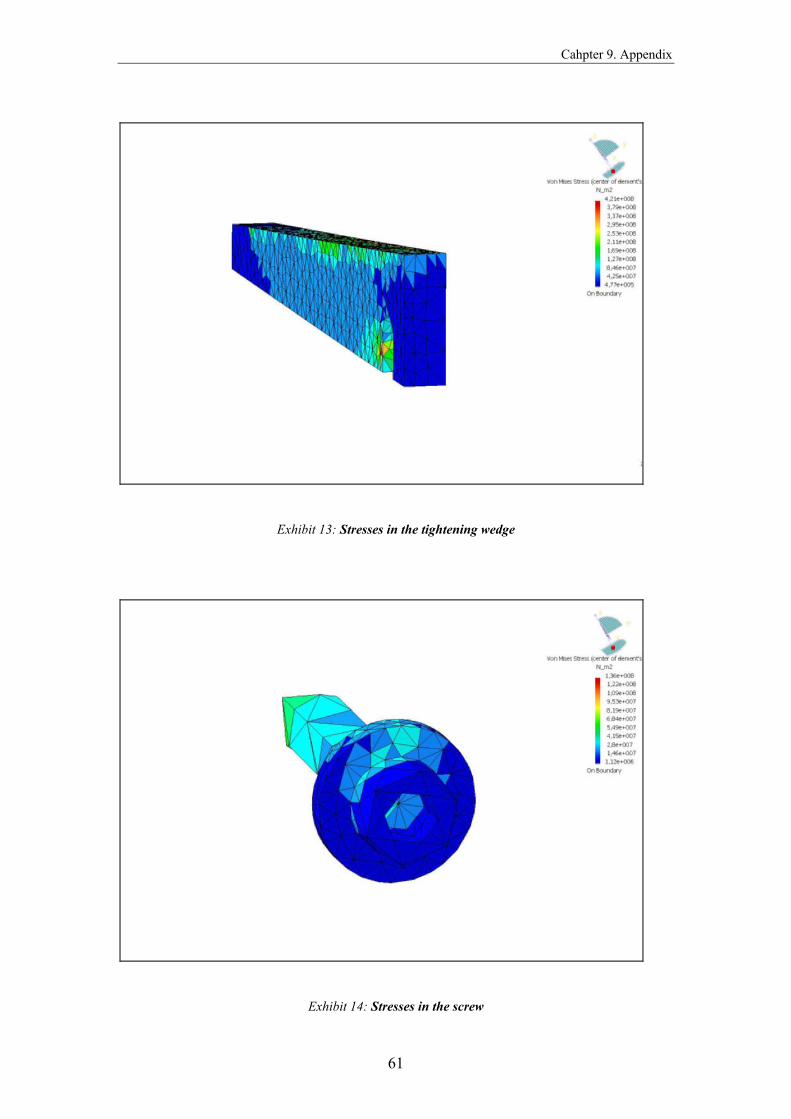
Exhibit 13: Stresses in the tightening wedge
Exhibit 14: Stresses in the screw

Cahpter 9. Appendix
62
Exhibit 15: Estimated local errors
Exhibit 16: Estimated local error in the main body

Cahpter 9. Appendix
63
Exhibit 17: Estimated local error in the blade
Exhibit 18: Estimated local error in the support wedge

Cahpter 9. Appendix
64
Exhibit 19: Estimated local error in the tightening wedge
Exhibit 20: Estimated local error in the screw
Cahpter 9. Appendix
65
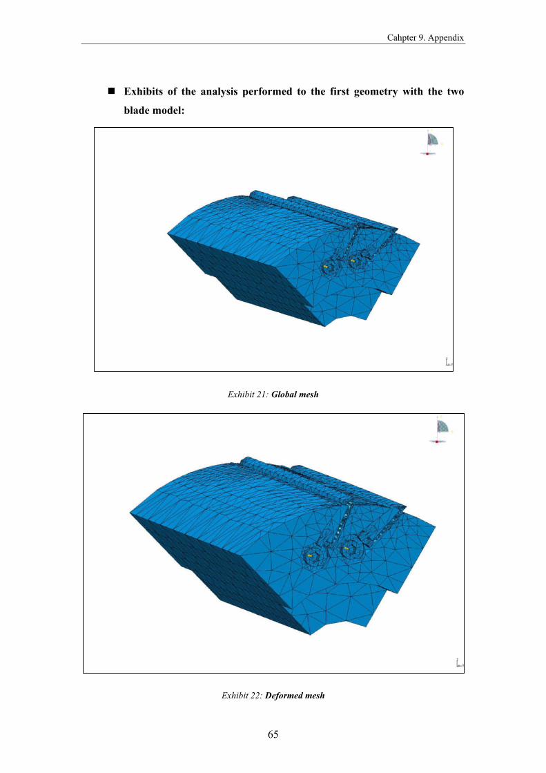
Exhibits of the analysis performed to the first geometry with the two
blade model:
Exhibit 21: Global mesh
Exhibit 22: Deformed mesh
Cahpter 9. Appendix
66
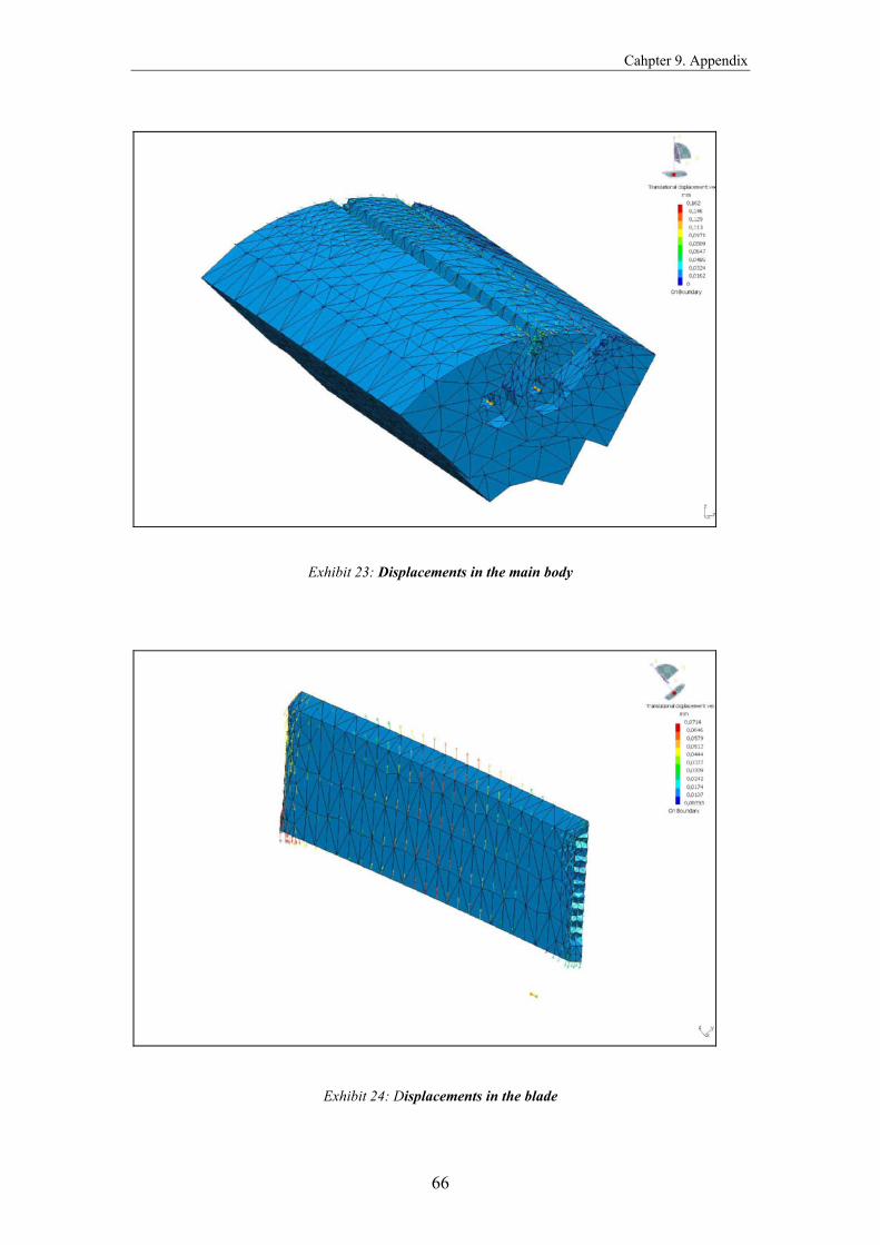
Exhibit 23: Displacements in the main body
Exhibit 24: Displacements in the blade
Cahpter 9. Appendix
67
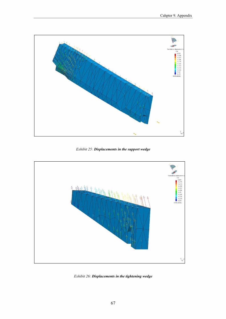
Exhibit 25: Displacements in the support wedge
Exhibit 26: Displacements in the tightening wedge

Cahpter 9. Appendix
68
Exhibit 27: Displacements in the screw
Exhibit 28: Stresses in the main body

Cahpter 9. Appendix
69
Exhibit 29: Stresses in the blade
Exhibit 30: Stresses in the support wedge
Cahpter 9. Appendix
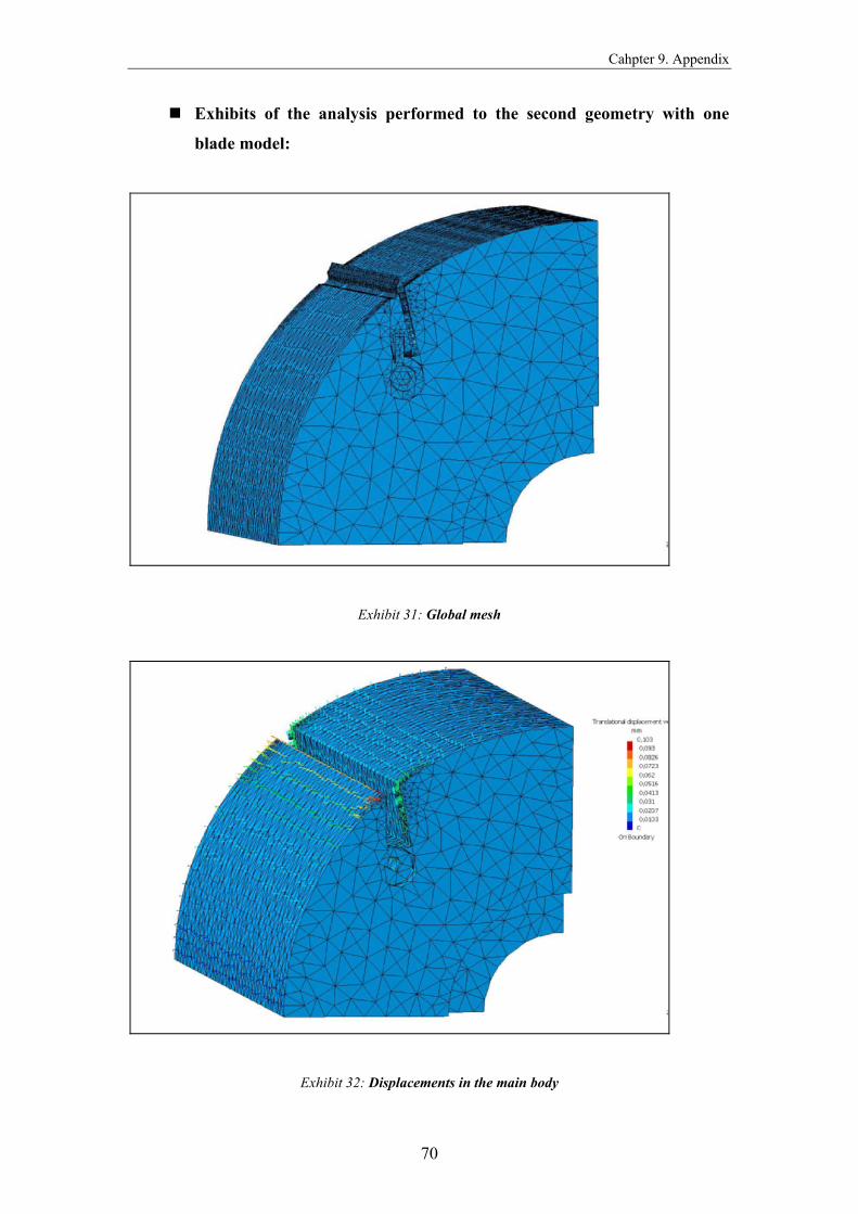
70
Exhibits of the analysis performed to the second geometry with one
blade model:
Exhibit 31: Global mesh
Exhibit 32: Displacements in the main body
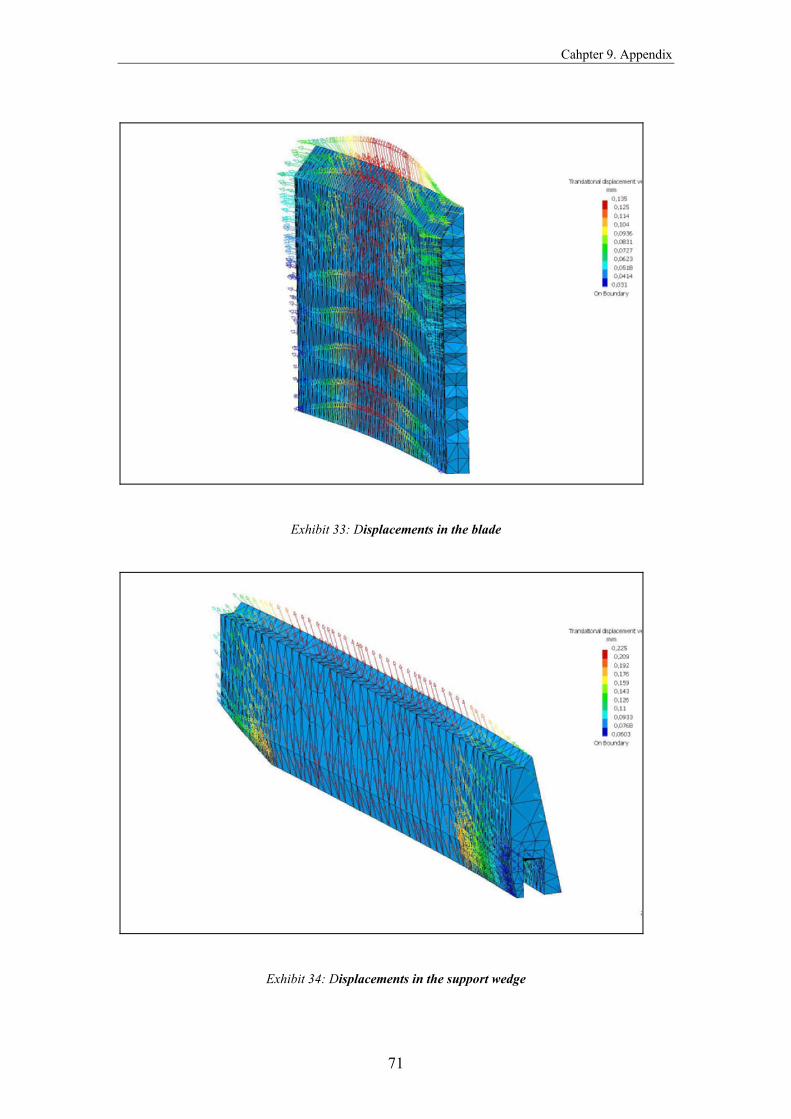
Cahpter 9. Appendix
71
Exhibit 33: Displacements in the blade
Exhibit 34: Displacements in the support wedge
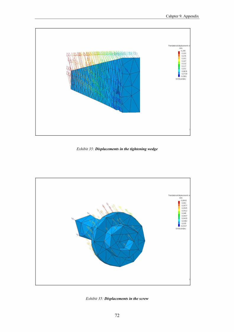
Cahpter 9. Appendix
72
Exhibit 35: Displacements in the tightening wedge
Exhibit 35: Displacements in the screw
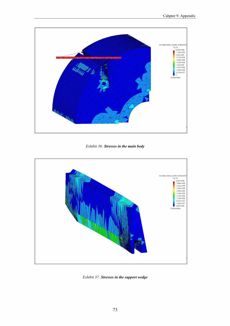
Cahpter 9. Appendix
73
Exhibit 36: Stresses in the main body
Exhibit 37: Stresses in the support wedge

Cahpter 9. Appendix
74
Exhibit 38: Estimated local error in the main body
Exhibit 39: Estimated local error in the blade

Cahpter 9. Appendix
75
Exhibit 40: Estimated local error in the support wedge
Exhibit 41: Estimated local error in the tightening wedge

Cahpter 9. Appendix
76
Exhibit 42: Estimated local error in the screw
List of References
77
LIST OF REFERENCE
Books
- King, R. I. (1985), Handbook of High Speed Machining Technology,
Chapman and Hall, New York, London
- J. Toby Mottram and C.T. Shaw, Using Finite Elements in Mechanical
Design, McGraw Hill
- A.A. Becker, Finite Element Analysis, Professional Engineering
Publishing
- M.H. Aliabadi and C. A. Brebbia, Computational Methods in Contact
Mechanics, Elsevier Applied Science
- T.R. Chandrupatla, A.D. Belegundu, Introduction to Finite Elements in
Engineering, Second Edition, Prentice Hall
- Beez Andreas, Safe Design of High Speed Milling Tool, Linköpings
Universitet, Institute of Technology, Department of Mechanical
Engineering, Production System Division
- Handbook of the 15th International Wood Machining Seminar, July
2001, Los Angeles, California, USA.
- Principles of Wood Science and Technology
Standards
- EN 847 Tools for woodworking: Safety requirements – Part 1
- Swedish Standard 14 2541, Steel for Hardening and tempering
- Swedish Standard 14 2172, Structural Steel
- Swedish Standard 14 2142, Microalloyed Steel
- Swedish Standard 14 2090, Spring Steel
- Swedish Standard 14 2722, High Speed Steel
Internet
- http://www.weinig.de
- http://www.waco.se
- http://www.springer-maschinen.com