fea information inc. worldwide news for june 2007 · dep · meshworks suite of tools ... ls-prepost...
TRANSCRIPT

W W W . F E A I N F O R M A T I O N . C O M
D E P
· M e s h w o r k s S u i t e o f T o o l s
i n c l u d i n g M o r p h e r
a n d R a p i d M e s h e r
V a r m i n t A l ’ s
R i f l e B a r r e l
D y n a m i c P r e s s u r e A n a l y s i s
J U N E2 0 0 7
F E A I N F O R M A T I O N R E S O U R C E M A G A Z I N E
I N F O R M AT I O N
P U R D U E U N I V E R S I T Y
V i d e o
S i m u l a t e s
9 / 1 1 A t t a c k s

FeaInformation.com 1
Announcements: New Participant:
Detroit Engineered Products: a Michigan based engineering consulting and software products firm specializing in the area of Product Development products and solutions. All of the products and services are aimed at reducing the overall product development cycle and bring products faster to market.
FEA Announcement New AVI in Library – LS-DYNA & LS-PrePost for Hot Stamping A Sheet Metal Part LS-PrePost Tutorial 6 Updated to include new LSTC Hybrid III Rigid 50th Percentile Dummy
We have added to our Resource Page
Table 1
SUN Sparc 5.8 and above
SUN Opteron 5.8 and above Table 2
SUN Sparc 5.8 and above
SUN Opteron 5.8 and above LAM/MPI
Sincerely, Art Shapiro [email protected] Marsha J. Victory [email protected]

FeaInformation.com 2 Table Of Contents 01 Announcements
02 Table of Contents
03 LS-DYNA – Purdue University - Video simulates 9/11 attacks
07 OASYS - The advanced toolkit for LS-DYNA
09 DEP – Detroit Engineered Products
11 Varmint Al’s FEA Rifle Barrel Dynamic Pressure Analysis of a 6PPC With and Without tuner
14 Training Class – Modeling of Blast & Penetration with Applications To Protective Structures, Vehicles and Homeland Security Threats
15 LS-DYNA & LS-PrePost For Hot Stamping Sheet Metal Parts
16 Yahoo Yammerings
18 June carhs.training gmbh
19 LS-PrePost Update
20 LSTC Training Classes
21 TopCrunch Announcement
23 LS-DYNA and Other Worldwide Events
24 FEA Information China Participants
25 Market Place
26 Resource Pages
38 Press Releases • Intel • IBM
FEA Information Inc. & News: Editor Art Shapiro Graphic Designer Wayne L. Mindle Business Manager Trent Eggleston President Marsha J. Victory
FEA Information News: Technical Writers: Dr. David Benson Dr. Ala Tabiei Uli Franz Suri Bala Writing Consultants: Steve Pilz – Reza Sadeghi

FeaInformation.com 3
FEA Information Worldwide News Interest Report.
Video simulates 9/11 attacks - internet postings by A. Giaccana, FEA Information Inc. , Technical Writer
I feel the following is of importance to bring to the attention of our engineering community:
All links are listed at the end of this article - information is © Copyright to CNN.com and/or Purdue University
On CNN.com (June 21, 2007) there is an interesting posting by Chris Kokenes titled Video simulates 9/11 attacks.
The posting covers a computer simulation posted on YouTube by Purdue University researchers depicting the attack on our World Trade Center, in New York, USA, on September 11, 2001.
The article/simulation movie has significant importance in our FEA community, due to the simulations were run by Purdue University. Purdue Univeristy is a long time and important user of the state of the art simulation code, LS-DYNA, as posted on the Purdue LS-DYNA Simulation website:
September 11 WTC Attack Simulations Using LS-DYNA
Phase III, as of September 10, 2006
• Mete A. Sozen, • Ayhan Irfanoglu, • Christoph M. Hoffmann
The Larger Team and Responsibilities
Project Conception
Mete Sozen, Civil Engineering
Project Direction
Christoph Hoffmann, Computer Science, CRI
Simulation Setups
• Ayhan Irfanoglu, Civil Engineering • Oscar Ardila-Giraldo, Civil
Engineering
• Ingo Brachmann, Civil Engineering
Computing Infrastructure Support
• Information Technology at Purdue Rosen Center for Advanced Computation
• Bowen Civil Engineering Laboratory • Northwest Indiana Computational
Grid • Network for Computational
Nanotechnology
Project Funding
NSF-ITR DSC-0325227, A. Sameh, PI
Mesh Generation Post Processing
• Christoph Hoffmann, Computer Science
• Paul Rosen, Computer Science
Engineering Models
• Ayhan Irfanoglu, Civil Engineering • Oscar Ardila-Giraldo, Civil
Engineering • Ingo Brachmann, Civil Engineering
Scientific Supervision
• Mete Sozen, Civil Engineering
Supercomputer Runs
• Paul Rosen, Computer Science
Animation
• Voicu Popescu, Computer Science
Physical Experiments
• Santiago Pujol, Civil Engineering

FeaInformation.com 4
Graduate Students
• Oscar Ardila-Giraldo, Civil Engineering
• Ingo Brachmann, Civil Engineering • Tyler Krahn, Civil Engineering • Paul Rosen, Computer Science
Problem Statement
Simulate as faithfully as possible the effects of crashing an air frame loaded with fuel (simulating a Boeing 767-200ER) into a steel and concrete structure similar to the structure of the WTC-1, North Tower, of the World Trade Center.
Purpose of the Effort
Use the simulation results to understand what the extent of damage done by the impact has been. Effects of the subsequent fire are not under consideration in this phase of the project.
Use the simulation results also to construct animations and visualizations that vividly reenact of the impact, as it plausibly has been.
This work will be Phase IV.
Simulations
The fully configured impact simulations are runs 11 and 12. Earlier runs calibrated and refined the simulation setup.
The modeled airframe is loaded with the approximate amount of fuel and set to impact the WTC-1 building (the North Tower) at the speed, position and orientation published in official reports. Both the exterior building skeleton and the core support structure of the building have been modeled, as well as the concrete floors and supporting girders.
Simulation Parameters
The simulation uses adaptive time stepping which averages to approximately 0.000001 sec time steps. We generate snapshots of the simulation approximately every 0.0025 sec. The airplane arrives with an initial velocity of 470 mph. Penetration to the core structure of the building takes approximately 0.1 sec.

FeaInformation.com 5
Animations and Stills
Simulation Animations and Stills – Hyperlinks have been removed – please visit to activate the animations
Problem Size (nodes)
Compute Time (nano-regatta)
North Tower Simulation Run 11
327 K
100 hours, 8 processors, 0.5 sec
North Tower Simulation Run 12
327 K
30 hours, 16 processors, 0.37 sec

FeaInformation.com 6
Calibrations and Experiments
The aircraft model was constructed from publicly available data. The FEA model has been calibrated by computing mass distributions and evaluating the Riera curve.
From our modeling of the aircraft crash into the Pentagon building, we knew that a critical issue in defining the damage was the modeling of the fuel in the aircraft. Much of the mass of the aircraft is provided by the fuel; in this case about 27%. The energy imparted to the impacted structure is the initial cause of the damage. This time, we modeled the fluid-structure interaction using smooth particle hydrodynamics (SPH). To
calibrate our approach, Dr. Pujol built a special test setup that made it possible to hurl 6-oz liquid containers at a steel target of varying speeds approaching 100 m/sec.
Support
This work has been supported in part by NSF ITR grant DSC-0325227; the PI of the grant is Dr. Sameh, the NSF officer is Frederica Derema. For the work of the larger ITR project see the project website.
Infrastructure support for the large-scale simulations has been provided by the Northwest Indiana Computational Grid (NWICG), and by Purdue's Network for Computational Nanotech
Direct Links to the above information
Article On CNN: Simulation Movie
Purdue LS-DYNA Simulation Site:

FeaInformation.com 7 OASYS SOFTWARE -The advanced toolkit for LS-DYNA
The Oasys Suite of software contains some of the most advanced pre/post processing functions for LS-DYNA. It is used by many of the largest LS-DYNA customers worldwide. Primer version 9.3 RC1 was released in February; imminent future releases will include full compatibility with the 2007 LS-DYNA 971 manual and many more new features in both Primer and the post-processing software.
Some of the new features in version 9.3 Oasys PRIMER Mechanisms and Dummies
• Define mechanisms by specifying
how a series of parts are intercon-nected, e.g. the linkages of a seat.
−• Position and re-position by drag-ging into position, entering pre-defined coordinates (e.g. for the H-point), or retrieving previously stored positions.
−• The same dragging and position-ing capabilities are now automati-cally available for dummy models, using the existing dummy tree data.
−• Seat and dummy can be linked to-gether allowing both to be posi-tioned in a single operation.
−• Seat foam can be compressed to prevent penetration by the dummy. Two methods are avail-able: an automatic geometric method within Primer, or assisted creation of an LS-DYNA seat com-pression analysis followed by re-import of the deformed geometry and stresses.
−• In version 9.3 RC2, the seat-belt can be refitted quickly to suit the new dummy position.
Oasys PRIMER Cut sections
Sections may be cut through the model, showing cut edges of shell elements with their true thickness. The section can be dragged through the model.
Oasys PRIMER Spotwelding
Create and modify solid element spotwelds, including the new mul-tiple solid element (nugget) spot-weld assemblies. A new Connec-tions Table allows easy modifica-tion and error-fixing.
Oasys T/HIS Multiple graphs and multiple pages
Multiple graph windows laid out on multiple pages allow large amounts of data and several mod-els to be easily viewed and man-aged.

FeaInformation.com 8 Oasys D3PLOT Background images and movies
Background images and movies can now be read into D3PLOT and the results viewing angle easily adjusted to match the background image. The timing and speed of movies can also be synchronised so that test and analysis results can easily be compared.
Oasys D3PLOT Used Defined Data Components
Users are able to specify and con-tour their own data components, either by a formula applied to LS-DYNA data components, or by data read in from external files. This is useful for displaying spe-cialist results such as failure crite-ria, stress combinations, data generated by external scripts, etc.
Oasys REPORTER Contour-plotting of HIC
After performing multiple head impact analyses to provide HIC values at each impact point, a contour plot can be generated in Reporter and the percentage area calculated over which the HIC re-quirement is satisfied.
Arup Contacts for Oasys Software: UK - Hazel Partridge Arup Group Ltd - UK +44 (0) 121 213 3399 [email protected]
China - Kimbal Virdi Arup Group Ltd - China +86 (0) 21 6126 2875 [email protected]
India - Lavendra Singh nHance Engineering Solutions (P) Ltd Indian Operation - Oasys Ltd (Arup) +91 (0) 40 235 44420 [email protected]
USA - Simon Iregbu Arup Group Ltd - Detroit +1 248 822 5050 [email protected]
Other Worldwide Distributors of Oasys Software: Alyotech (France) www.alyotech.fr Dynamore (Germany) www.dynamore.de ERAB (Scandinavia) www.erab.se Japan Research Institute (Japan) www.jri-sol.co.jp THEME engineering (Korea) www.lsdyna.co.kr

FeaInformation.com 9
Website For Complete Information DEP
COMPANY OVERVIEW Detroit Engineered Products (DEP) is an advanced Computer Aided Engineering (CAE) software products and services to major manufacturing and design cus-tomers worldwide. Our core strengths are :
• Meshworks Suite of Tools including Morpher and Rapid Mesher
• Advanced Product Design (CAD) and Engineering (CAE) Consulting including Crash, NVH and Durabil-lity
• Design Optimization including Multi Disciplinary Optimization
• Advanced knowledge based engi-neering wizards
Companies around the world have gained tremendous efficiencies in their product development process using the Meshworks suite of technologies and now this technology is gaining significant traction in the aerospace companies . MESHWORKS SUITE OF HIGH PRODUCTIVITY TOOLS A.) “MESHWORKS MORPHER” is a path breaking software that enables the user to rapidly change an existing FE / CFD Mesh into a new target shape with-out having to redraw it in the CAD sys-tem. This disruptive new technology saves significant time and money for new product development. Major Auto-
motive, Aerospace and Consumer Elec-tronics companies are early adopters of this technology by licensing the product. The MESHWORKS MORPHER tools can be used through out the product develop-ment phase of any product:
Early Product Development: In the case of the automotive rapid full vehicle CAE models can be generated using the Meshworks Morpher in less than 5 days. Exist-ing full vehicle models can be mapped to new vehicle styling themes in a matter of hours. Simi-lar solutions have been used by other industries like cell phones, aerospace. Components. This al-lows the manufacturer to rapidly predict if the proposed new styling will meet performance criteria.
Intermediate Product Devel-opment: Once the initial styling has been decided section changes can be morphed very easily using the parametric approach. This is called “Rapid Analytical Mule” de-velopment. Detailed Product Engineering: The mesh morphing tool is a ma-jor shape change enabler that helps parameterize models by providing intelligence to several design parameters. Once the intel-ligence is imparted, several de-signs can be evaluated for their performance against a particular criteria and designs can be opti-mized for criteria like mass, dura-bility etc.

FeaInformation.com 10
B.) KNOWLEDGE BASED ENGG. WIZARDS: A new class of engineering software that addresses the needs of product design engineers has been in the market for will be developed and mar-keted. These ‘Wizard’ like tools are built off existing product knowledge base and are aimed at the much wider product en-gineers’ market. These Wizards yields a productivity gain of nearly 5 x
* These KBE tools guide the product de-velopment team in a step by step fash-ion. This tool would have a collected in-telligence of the particular product built in and the user has to provide input at a fairly high level. Also best practices of the product design and manufacturing can be incorporated in the tool.
*

FeaInformation.com 11 Varmint Al’s FEA (Finite Element Analysis) Rifle Barrel Dynamic Pressure Analysis of a 6PPC With and Without a Tuner For those of you who don’t know of Varmint Al, he worked for 30 years at the Lawrence Livermore National Laboratory. For most of that time, he worked performing engineering structural analysis on complex systems. Please visit Varmint Al’s for additional informa-tion. Complete Movie And Article can be viewed at Rifle Barrel
OBJECTIVE.... The objective of this study was to gain some insight and un-derstanding on what a tuner does to the motions of the rifle barrel and how a muzzle tuner might affect the accuracy of a rifle. The calculation loads simulates the gas pressure traveling up a rifle bar-rel behind the bullet. The deformations in the barrel are calculated and then a 100 yard projection of the barrel's muzzle is displayed. I chose the 6PPC caliber be-cause it is the most popular caliber of the benchrest community. I have per-sonally never participated in a benchrest match. However, I am interested in rifle accuracy and how to improve accuracy since varmint hunting also requires very accurate rifles.
POWERFUL TOOL.... This analysis was done with the LS-DYNA Finite Element Code. This software is a very powerful tool for analyzing the dynamic and static loading of structures. It was used here to calculate the barrel's response to the high pressure gas that forces the bullet out of a barrel when it is fired. For the first calculation, the breach end of the
barrel was fixed in space which treats the barrel as a cantilever beam. The re-sults showed that a more complex model was required to capture the dynamics of the complete rifle. There is a vertical plane of symmetry in the model and only motions in the vertical direction are cal-culated. In the movies, the displace-ments are greatly amplified so that they can be viewed.
THE BARREL.... The 416 Stainless Steel barrel in this model has a breach diame-ter of 1.5" for 4 inches and then a straight taper to a diameter of 0.8" at a distance of 20". The diameter is 0.8" from there to the end of the barrel at 22". The caliber is 6mm with no rifling modeled. The two inch long 416 Stainless Steel tuner has an 0.8" ID and the OD is 1.5" and extends 1" beyond the muzzle in the initial position. This barrel weighs 6.42 pounds . The full rifle is in a one G gravitational field to simu-

FeaInformation.com 12
late earth's gravity. The burning pow-der's gas pressure travels up the barrel by one inch increments to match the bul-let's progress and the pressure vs time curve. The barrel's chamber is the ap-proximate size of the 6PPC caliber brass. But for the calculation, I did not include the brass case and merely applied the pressure to the bolt face, the chamber walls, and the barrel bore.
THE ACTION.... The action is 1.5 inches in diameter and is 7.2 inches long. The weight of the action is 2 pounds. The bolt is merged into the actions volume. The gas pressure acts on the bolt face. Since there is no bolt, there is also no bolt handle.
THE SCOPE AND RINGS.... The scope weighs approximately 25 oz and is alu-minum with a 0.1 inch wall thickness. There is a simulated lens in both the eyepiece and the objective to stiffen the otherwise open ends. The scope rings are also aluminum and are bonded to the action and scope.
THE STOCK.... The stock has the me-chanical properties of wood. The action is "glued in" to the stock and the barrel is completely free floated. The stock is supported at two places, one 2 inch sec-tion near the butt and another 2 inch section on the forearm. The complete ri-fle is allowed free recoil, that is no shooter's shoulder is modeled.
THE TUNER....
The 1.5 inch diameter tuner is 2 inches long with 0.8 inch diameter bore. One
inch of the tuner is bonded to the bar-rel's last inch, to simulate a threaded joint, and there is one inch of overhang past the muzzle. The mechanical proper-ties of the tuner are that of 416 Stainless Steel except for the density. The density was adjusted for tuner weights of 8 oz and 16 oz. Adjusting the tuner density was a one number change compared to making a new mesh for each weight. The results from the calculations should not be affected by the easier procedure of changing the density.
THE 3-D MESH....
This view shows the mesh detail. Only half of the mesh is actually in the calcu-lation. There is a vertical plane of sym-metry (X-Z Plane) down the bore axis and the center of the stock. The mesh is reflected across this plane for the for this 3-D mesh picture. The boundary condi-tion for the calculation forced all nodes on the symmetry plane to remain on the plane, but the nodes are allowed to move while remaining on the plane. For the 3-D model without a tuner, there are 16,053 nodes and 11,428 elements. For the model with the tuner, there are 16,913 nodes and 12,004 elements. Every microseconds of pressure vs time data, the conditions of the model were stored for post-processing. Full Rifle Model Weights and CG Loca-tions

FeaInformation.com 13
Item
No Tuner
Weight (lb)
Tuner 8 oz (lb)
Tuner 16 oz (lb)
Barrel 6.42 6.42 6.42 Action 2.00 2.00 2.00 Stock 3.00 3.00 3.00 Scope 1.56 1.56 1.56 Tuner 0 0.5 1.0 Total 12.98 13.48 13.98
(in) (in) (in) X - CG Below Bore
0.4344 0.4183 0.4028
Z - CG Forward
of Bolt Face
1.8359 2.5800 3.2694
CONCLUSION.... Maybe the "consen-sus" was that a rifle barrel vibrated in one or more of the mode shapes when fired. Maybe that was because the mode shapes and frequencies were easy to cal-culate and they did seem to answer some of the questions. From these dy-namic pressure calculations, it appears that the forced deformations and recoil are much more important than the natu-ral vibration modes in determining where a barrel is pointing. Put another way, consider a guitar string being plucked. One pulls the string into a position (forced position) then releases it and the string vibrates at is natural frequency. The bullet "pulls" the rifle barrel to a new shape and once the bullet leaves the barrel, then the barrel vibrates. How-ever, the addition of the scope to the model has shown some small high fre-quency vibrations superimposed on the forced deformations, both of which, alter where the muzzle points before the bul-let exits. For lowering the amplitude of the high frequency vibrations, it appears that even an "out of tune" tuner is better than no tuner at all.
Visit Varmint Al for the continued article Sections:
• Full Rifle – Dynamic Response During Firing
• Full Rifle & 16 oz Tuner - Dynamic Response During Firing
• Mode Shapes and Natural Fre-quencies
• Five Shot Groups With/Without A Tuner
• Five Separate Pressure vs Time Data
• Five Shots 6PPC No Tuner • Five Shots 6PPC With 16 oz Tuner • Bloop Tube added to the Muzzle • The Pressure vs Time Input Data • Calculate The Muzzle Velocity and
Distance Timing
Good Hunting. from Varmint Al
A Few Quotes From Varmint Al’s Quote Section:
• My goal in life is to be as good of a person my dogs thinks I am.
• If your dog is fat, you aren't getting enough exercise.
• "Hold my beer while I run the calculation." Redneck Engineer
• The critical thinking required for engineering analysis is hard work and like weight lifting for the brain. Varmint Al
• An effective way to deal with predators is to taste terrible.

FeaInformation.com 14 Modeling of Blast & Penetration with Applications To Protec-tive Structures, Vehicles and Homeland Security Threats
New LS-DYNA Training Class Presented by Paul Du Bois Len Schwer, Ph.D. Beratender Ingenieur Schwer Engineering & Consulting Services
Next Offerings: 24 & 25 Sep 07 LSTC Offices Livermore, California, USA 9 & 10 Oct 07 before DYNAmore German User Forum, Frankenthal, Germany
Abstract
This class focuses on the application of LS-DYNA for the simulation of high en-ergy events. The analysis methods, and modeling, are illustrated through case studies. An emphasis is placed on model-ing techniques: guidelines for which technique(s) to select, insights into which techniques work well and when, and possible pitfalls in modeling choice selections. Sufficient mathematical the-ory is presented for each technique, es-pecially Eulerian and Meshfree Methods, to provide the typical user with adequate knowledge to confidently apply the ap-propriate analysis technique.
Intended Audience
This training class is intended for the LS-DYNA analysts with a comfortable com-mand of LS-DYNA keywords and options associated with typical Lagrangian analy-ses. The training class will attempt to provide the analyst with the additional tools and knowledge required to model the above described class of high energy events. The typical attendee is likely to have a background in defense applica-tions, to include protective structures and vehicles, Homeland Defense topics, and terrorist threat mitigation tech-niques. Because the class uses example problems to illustrate concepts and tech-niques, numerous modeling ‘tricks’ and options are discussed, and this knowl-edge would benefit any LS-DYNA user.
Instructors
Paul Du Bois and Len Schwer have a combined experience base of over 50 years in the field of application of large scale numerical simulations, Most of this experience is commercial and military applications of LS-DYNA. The team teaching of this class provides the atten-dee with the unique experience of seeing topics presented from two different points of view, but with a shared view of the advantages and disadvantages of the techniques presented.
This new class has been well received by attendees at the first offering in 2006 preceding the DYNAmore German Forum in Ulm, Germany, and more recently in 2007 at Rafael in Haifa Israel, and to a sold out group at the recent LS-DYNA European User Conference in Gothen-burg, Sweden.
A detailed description of the class is available from the LSTC training web page: www.lstc.com/pages/classes.htm Blast & Penetration PDF File
Class By Len Schwer at LSTC: Concrete and Geomaterial Modeling

FeaInformation.com 15 LS-DYNA Featured AVI LS-DYNA hot stamp a sheet metal part Using LS-PrePost Complete AVI can be viewed at: www.feainformation.com – top bar link “AVI Lib” AVI 31a In the Metal Forming Simulation Section
Shown in the movie hot_stamping.avi are the manufacturing steps required to hot stamp a sheet metal part. The blank is first heated to the austenization temperature, about 950C. The blank is then transferred to the dies. During the transfer the blank decreases in temperature due to heat lose to the environment by convection and radiation. The blank is placed on the lower die. The blank bottom surface thermal boundary conditions during the transfer process must be turned off as contact with the lower die now controls the heat transfer process. This causes a temperature gradient to occur through the thickness of the blank. The dies close forming the part. The part is held in the dies for several seconds to quench the material causing a phase transformation to martensite. The movie shows the blank cooling and the dies heating up. Notice the serpentine tem-perature pattern occurring on the lower die surface. This is caused by the serpentine cooling passages in the lower die. The second part of the movie shows the cooling fluid passing through these passages. Colder fluid pushes the hot fluid from the stamping process out of the tubes, thereby cooling the die for the next stamping and quenching process.
LS-DYNA FOR METAL FORMING SIMULATION Free 30-day demonstration agreement
for LS-DYNA, LS-PrePost, LS-OPT for Metal Forming Simulation

FeaInformation.com 16
Yahoo Group Yammerings Questions/responses, from postings to the LS-DYNA Yahoo Group. Copyright © Jim Kennedy and Len Schwer Note: LS-DYNA Yahoo Group is neither owned nor operated by LSTC, and LSTC has no control over the content. This installment of “Yahoo Yammerings” features several questions, with re-sponses, from the past month of postings to the LS-DYNA Yahoo Group. Questions:
1. How to hide the material information in LS-DYNA input file? 2. Contact between beam elements and shell elements? 3. The scalar damage of material 72Rr372R3?
1. How to hide the material informa-tion in LS-DYNA input file?
My company wants to outsource an analysis job to another company. We want to use our own material property. But it's risk for us to reveal the secret dataprotect our material property data. So iIs there any method to hide the ma-terial information in dyn input file? Just like an external link to call the material database.
Reply by Chen Tsay
The new version of ls971.r3 can encrypt any keyword lines using a LSTC pgp key. You need to get obtain the latest version of LS-DYNA from LSTC.
2. Contact between beam elements and shell elements?
I have been trying to model contact be-tween a beam element (which represents the bolt) and shell elements with a hole (which represent the steel sheets that are bolted) with no success. I have used nodes_to_surface, automatic_general, and automatic_general_interior, but I always see the beam element nodes passing from one side of the sheet to the other without detecting contact.
Reply by Gareth Jones
I have been having a similar problem de-fining contact between beam elements and the edges of solid elements. I did a number of test runs with a few elements to try to solve this. My final solution was to put beam elements with a small di-ameter on the edges of my solids, and assign to these a *MAT_NULL material. I then used *CONTACT_AUTOMATIC_GENERAL, with SOFT=1 (on optional Card A). I expect this approach will also work with your shell element problem.
I would like to know if there is a better way of doing this, i.e. without having to define the null beam elements.
Reply by Jim Kennedy
For your information, Jason Husband of QuEST provided the following comment involving edge penetration:
“I was having edge penetration issues and ended up fixing the problem by assigning a ‘chicken-wire’ grid of null beams (overlaid on shells) and defined *automatic_general on this grid. Worked perfectly.”
A comment worth repeating that has been borrowed from the different contact notes is:

FeaInformation.com 17
The main feature of the AUTOMATIC_GENERAL option is that shell edge-to-edge and beam-to-beam contact is treated auto-matically. All free edges of the shells and all beam elements are checked for contact with other free edges and beams. Unlike SINGLE_SURFACE_CONTACT, AUTOMATIC_GENERAL checks for contact along the entire length of beams and exterior shell edges, not just at the nodes.
3. The scalar damage of material 72R3?
I would like to askhave a question based onabout material 72R3. In the keyword manual it says that to determine the damage of the material it is necessary to set the NOUT, on Card 3, to 2. After run-ning the simulation, I realized the scalar damage display in LS-PREPOST has val-ues ranginges from 0-2. Is this correct? My understanding is that the values should be between 0 to 1.Based on my understand and reference papers the damage of material usually has value ranges from 0-1.
Reply by Conrad Izatt
My understanding of the damage output is that it does indeed range from 0-2. This is because there are three failure surfaces (initial yield, maximum stress, and residual stress) and therefore there are two ‘damage phases’ in between these surfaces. Damage values from 0-1 show the progress from the initial yield surface to the maximum stress surface. Damage values from 1-2 show the pro-
gress from the maximum stress surface to the residual stress surface.
About The LS-DYNA Yahoo Group
• The archives contains a wealth of information that can be helpful to any LS-DYNA user.
• There are over 2240 subscribers from all over the world, and grows by a hundred new subscribers ever few months. The group cur-rently averages about 300 mes-sage per month, i.e. about 10 message per day.
How To Subscribe:
• Send an email request to [email protected]
• Visit the Yahoo Groups web site http://groups.yahoo.com
How To Benefit from the Group
• Review the archives when you are seeking help on any topic related to LS-DYNA. NOTE: Questions and responses may have been edited for clarity & brevity.
• Generally, the quickest/best re-sponses are to those questions posed with the most specifics.
• General questions such as “How do I use XXX feature?” either go unanswered, or are answered by Jim Kennedy with links to appro-priate references in the growing LS-DYNA related literature, e.g. see the archive of LS-DYNA Con-ference proceedings at www.dynalook.com
Jim Kennedy KBS2 Inc. [email protected]
Len Schwer Schwer Engineering & Consulting Services [email protected]
FeaInformation.com 18
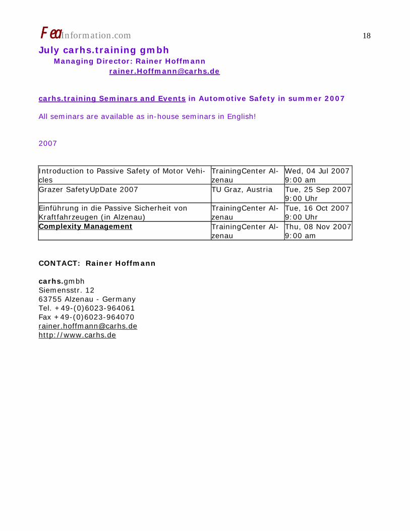
July carhs.training gmbh Managing Director: Rainer Hoffmann [email protected]
carhs.training Seminars and Events in Automotive Safety in summer 2007 All seminars are available as in-house seminars in English! 2007 Introduction to Passive Safety of Motor Vehi-cles
TrainingCenter Al-zenau
Wed, 04 Jul 2007 9:00 am
Grazer SafetyUpDate 2007 TU Graz, Austria Tue, 25 Sep 2007 9:00 Uhr
Einführung in die Passive Sicherheit von Kraftfahrzeugen (in Alzenau)
TrainingCenter Al-zenau
Tue, 16 Oct 2007 9:00 Uhr
Complexity Management TrainingCenter Al-zenau
Thu, 08 Nov 2007 9:00 am
CONTACT: Rainer Hoffmann carhs.gmbh Siemensstr. 12 63755 Alzenau - Germany Tel. +49-(0)6023-964061 Fax +49-(0)6023-964070 [email protected] http://www.carhs.de
FeaInformation.com 19
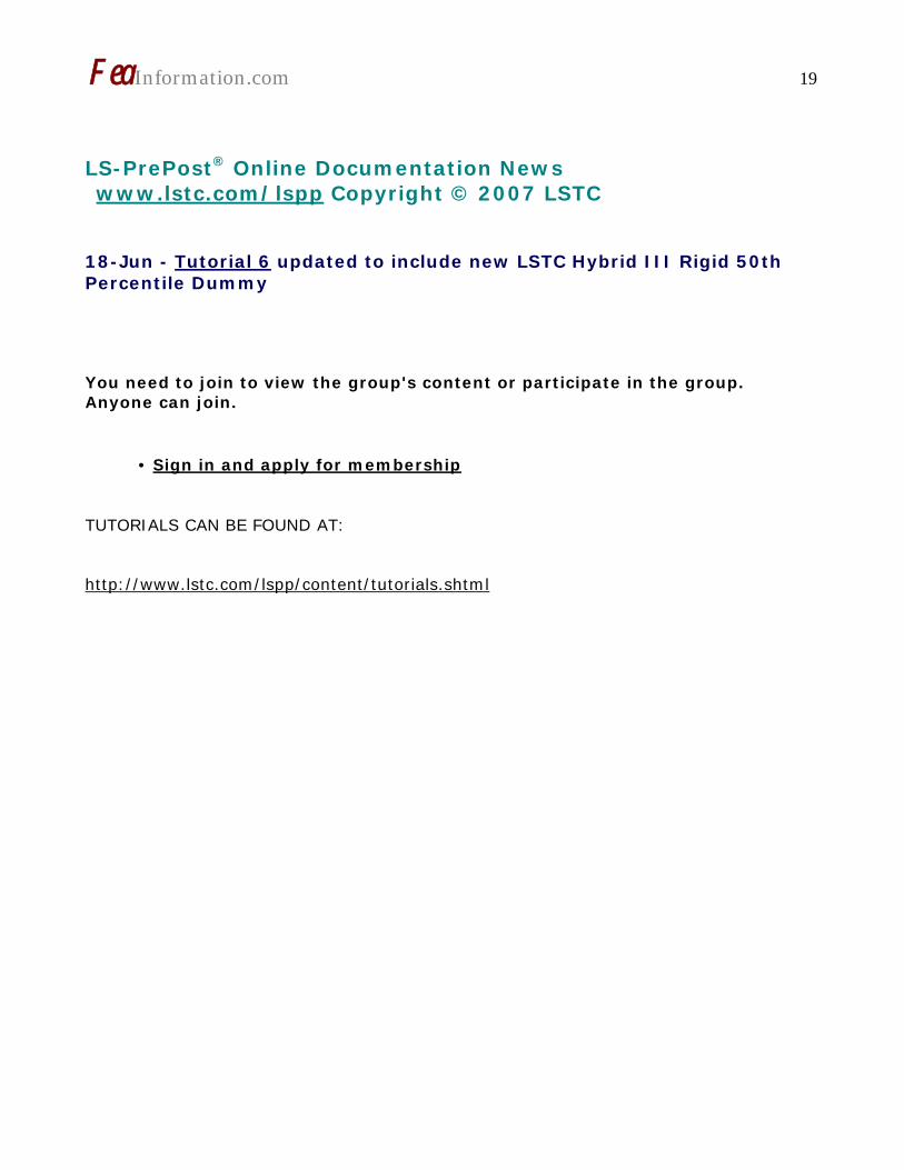
LS-PrePost® Online Documentation News www.lstc.com/lspp Copyright © 2007 LSTC
18-Jun - Tutorial 6 updated to include new LSTC Hybrid III Rigid 50th Percentile Dummy You need to join to view the group's content or participate in the group. Anyone can join.
• Sign in and apply for membership
TUTORIALS CAN BE FOUND AT: http://www.lstc.com/lspp/content/tutorials.shtml

FeaInformation.com 20 LSTC California & Michigan Training Classes July - August A complete list of dates can be found on the LSTC website July 11-13 CA Ale/Eulerian & Fluid/Structure Interaction 12-13 MI Advanced Options 30-Aug 02 CA Introduction to LS-DYNA August 20-21 MI Contact Sept 06-07 MI Advanced Options 11-14 MI Introduction to LS-DYNA 18-21 CA Advanced – Impact Analysis 24-25 CA Blast & Penetration October 22-25 MI Introduction to LS-DYNA November 01-02 CA Concrete Modeling and Geomaterial Modeling 12-15 CA Introduction to LS-DYNA December 10-11 MI Contact 12-13 MI Implicit
For Class Details: www.lstc.com

FeaInformation.com 21
Participant Benchmarks On TopCrunch. TopCrunch.org For Complete Vendor Submitted Benchmarks May 23rd HP/HP May 25th Intel/Mellanox Technolgies, Inc./Scali, Inc June 19th SGI May 23 – HP/HP CP3000/Linux/InfiniBand OFED
Intel Xeon 5160 3.0 GHz BL460c
8 x 2 x 2 = 32
557 neon_refined_revised
CP3000/Linux/InfiniBand OFED
Intel Xeon 5160 3.0 GHz BL460c
4 x 2 x 2 = 16
823 neon_refined_revised
CP3000/Linux/InfiniBand OFED
Intel Xeon 5160 3.0 GHz BL460c
2 x 2 x 2 = 8
1536 neon_refined_revised
CP3000/Linux/InfiniBand OFED
Intel Xeon 5160 3.0 GHz BL460c
1 x 2 x 2 = 4
3019 neon_refined_revised
CP3000/Linux/InfiniBand OFED
Intel Xeon 5160 3.0 GHz BL460c
1 x 1 x 2 = 2
4431 neon_refined_revised

FeaInformation.com 22 Participant Benchmarks On TopCrunch. TopCrunch.org For Complete Vendor Submitted Benchmarks May 23rd HP/HP May 25th Intel/Mellanox Technolgies, Inc./Scali, Inc June 19th SGI May 25 Intel/Mellanox Technolgies, Inc./Scali, Inc Clovertown Blades/Infiniband DDR, OFED 1.2
Intel Xeon Clo-vertown 2.66GHz
8 x 2 x 2 = 32 529 neon_refined_revised
Clovertown Blades/Infiniband DDR, OFED 1.2
Intel Xeon Clo-vertown 2.66GHz
4 x 2 x 2 = 16 918 neon_refined_revised
Clovertown Blades/Infiniband DDR, OFED 1.2
Intel Xeon Clo-vertown 2.66GHz
2 x 2 x 2 = 8 1709 neon_refined_revised
Clovertown Blades/Infiniband DDR, OFED 1.2
Intel Xeon Clo-vertown 2.66GHz
1 x 2 x 2 = 4 3359 neon_refined_revised
Clovertown Blades/Infiniband DDR, OFED 1.2
Intel Xeon Clo-vertown 2.66GHz
1 x 2 x 4 = 8 32578 3 Vehicle Collision
June 19 SGI/SGI Application Engineering Altix 4700/NUMAlink Intel Itanium 2
1600MHz 1 x 64 x 2 =
128 279 neon_refined_revised
Altix 4700/NUMAlink Intel Itanium 2 1600MHz
1 x 64 x 2 = 128
279 neon_refined_revised
Altix 4700/NUMAlink Intel Itanium 2 1600MHz
1 x 32 x 2 = 64
333 neon_refined_revised
.
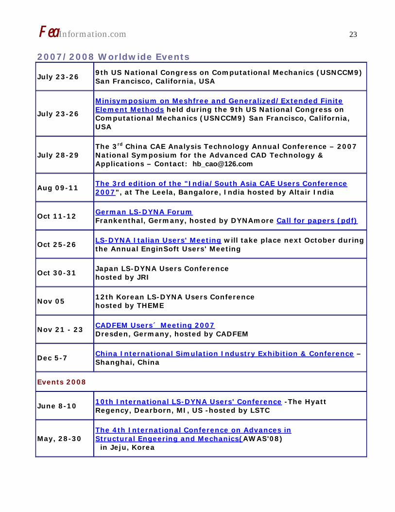
FeaInformation.com 23 2007/2008 Worldwide Events
July 23-26 9th US National Congress on Computational Mechanics (USNCCM9) San Francisco, California, USA
July 23-26
Minisymposium on Meshfree and Generalized/Extended Finite Element Methods held during the 9th US National Congress on Computational Mechanics (USNCCM9) San Francisco, California, USA
July 28-29 The 3rd China CAE Analysis Technology Annual Conference – 2007 National Symposium for the Advanced CAD Technology & Applications – Contact: [email protected]
Aug 09-11 The 3rd edition of the "India/South Asia CAE Users Conference 2007", at The Leela, Bangalore, India hosted by Altair India
Oct 11-12 German LS-DYNA Forum Frankenthal, Germany, hosted by DYNAmore Call for papers (pdf)
Oct 25-26 LS-DYNA Italian Users' Meeting will take place next October during the Annual EnginSoft Users' Meeting
Oct 30-31 Japan LS-DYNA Users Conference hosted by JRI
Nov 05 12th Korean LS-DYNA Users Conference hosted by THEME
Nov 21 - 23 CADFEM Users´ Meeting 2007 Dresden, Germany, hosted by CADFEM
Dec 5-7 China International Simulation Industry Exhibition & Conference – Shanghai, China
Events 2008
June 8-10 10th International LS-DYNA Users' Conference -The Hyatt Regency, Dearborn, MI, US -hosted by LSTC
May, 28-30 The 4th International Conference on Advances in Structural Engeering and Mechanics(AWAS'08) in Jeju, Korea

FeaInformation.com 24
FEA Information China Participants
Arup China: LS-DYNA sales, support, training
Name: Li YuQiang
Email: [email protected]
Tel 021 5396 6633 extn 151
Tsinghua University Qing Zhou, PhD. – Professor Department of Automotive Engineering Beijing, 100084, China
Engineering Technology Associates (China) Inc.
Martin Ma Tel: + 86-21-64385725 Contact: [email protected]
China Company Listings
Ansys-China, Inc. Tel: 86-10-84085558 Website: www.ansys.com.cn Contact: [email protected]
Hewlett-Packard Asia Pacific Ltd.
Jerry Huang Tel: +86-10-65645261 Contact: [email protected]
IBM China
Ms. Ling WANG - Tel: +86-10-6539-1188 x4463 (T/L:901-4463) Website: http://www.ibm.com/cn/ Contact: [email protected]
MSC. Software Corp. Tel: +86-10-6849-2777 Website: www.mscsoftware.com.cn Contact: [email protected]
SGI China Carl Zhang Tel: +86 -10 - 65228868 Ext. 3362 Contact: [email protected]
Zhong Guo ESI Co., Ltd Yang Xiaojum Phone: +86 (020) 8235 6272 Contact : Yang Xiaojun
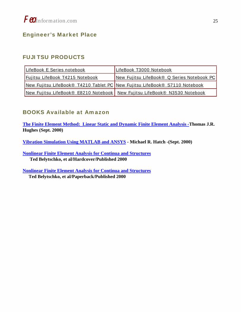
FeaInformation.com 25 Engineer’s Market Place FUJITSU PRODUCTS
LifeBook E Series notebook LifeBook T3000 Notebook
Fujitsu LifeBook T4215 Notebook New Fujitsu LifeBook® Q Series Notebook PC
New Fujitsu LifeBook® T4210 Tablet PC New Fujitsu LifeBook® S7110 Notebook
New Fujitsu LifeBook® E8210 Notebook New Fujitsu LifeBook® N3530 Notebook
BOOKS Available at Amazon
The Finite Element Method: Linear Static and Dynamic Finite Element Analysis -Thomas J.R. Hughes (Sept. 2000) Vibration Simulation Using MATLAB and ANSYS - Michael R. Hatch -(Sept. 2000)
Nonlinear Finite Element Analysis for Continua and Structures Ted Belytschko, et al/Hardcover/Published 2000
Nonlinear Finite Element Analysis for Continua and Structures Ted Belytschko, et al/Paperback/Published 2000

FeaInformation.com 26
LS-DYNA Resource Page - MPP Interconnect and MPI FEA Information Inc. Participant’s (alphabetical order)
Fully QA’d by Livermore Software Technology Corporation
TABLE 1: SMP - Fully QA’d by LSTC
AMD Opteron Linux
FUJITSU Prime Power SUN OS 5.8
FUJITSU VPP Unix_System_V
HP PA-8x00 HP-UX 11.11 and above
HP IA-64 HP-UX 11.22 and above
HP Opteron Linux CP4000/XC
HP Alpha True 64
IBM Power 4/5 AIX 5.1, 5.2, 5.3
IBM Power 5 SUSE 9.0
INTEL IA32 Linux, Windows
INTEL IA64 Linux
INTEL Xeon EMT64 Linux
NEC SX6 Super-UX
SGI Mips IRIX 6.5 X
SGI IA64 SUSE 9 with ProPack 4 Red Hat 3 with ProPack 3
SUN Sparc 5.8 and above
SUN Opteron 5.8 and above
FeaInformation.com 27
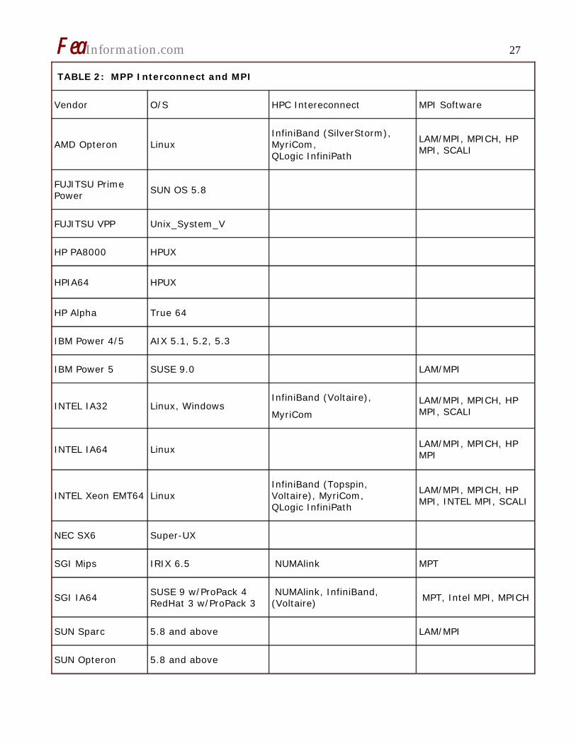
TABLE 2: MPP Interconnect and MPI
Vendor O/S HPC Intereconnect MPI Software
AMD Opteron Linux InfiniBand (SilverStorm), MyriCom, QLogic InfiniPath
LAM/MPI, MPICH, HP MPI, SCALI
FUJITSU Prime Power
SUN OS 5.8
FUJITSU VPP Unix_System_V
HP PA8000 HPUX
HPIA64 HPUX
HP Alpha True 64
IBM Power 4/5 AIX 5.1, 5.2, 5.3
IBM Power 5 SUSE 9.0 LAM/MPI
INTEL IA32 Linux, Windows InfiniBand (Voltaire),
MyriCom
LAM/MPI, MPICH, HP MPI, SCALI
INTEL IA64 Linux LAM/MPI, MPICH, HP MPI
INTEL Xeon EMT64 Linux InfiniBand (Topspin, Voltaire), MyriCom, QLogic InfiniPath
LAM/MPI, MPICH, HP MPI, INTEL MPI, SCALI
NEC SX6 Super-UX
SGI Mips IRIX 6.5 NUMAlink MPT
SGI IA64 SUSE 9 w/ProPack 4 RedHat 3 w/ProPack 3
NUMAlink, InfiniBand, (Voltaire)
MPT, Intel MPI, MPICH
SUN Sparc 5.8 and above LAM/MPI
SUN Opteron 5.8 and above

FeaInformation.com 28
LS-DYNA Resource Page - Participant Software
Interfacing or Embedding LS-DYNA - Each software program can interface to all, or a very specific and limited segment of the other software program. The following list are software programs interfacing to or having the LS-DYNA solver embedded within their product. For complete information on the software products visit the corporate website.
ANSYS - ANSYS/LS-DYNA
ANSYS/LS-DYNA - Built upon the successful ANSYS interface, ANSYS/LS-DYNA is an integrated pre and postprocessor for the worlds most respected explicit dynamics solver, LS-DYNA. The combination makes it possible to solve combined explicit/implicit simulations in a very efficient manner, as well as perform extensive coupled simulations in Robust Design by using mature structural, thermal, electromagnetic and CFD technologies.
AI*Environment: A high end pre and post processor for LS-DYNA, AI*Environment is a powerful tool for advanced modeling of complex structures found in automotive, aerospace, electronic and medical fields. Solid, Shell, Beam, Fluid and Electromagnetic meshing and mesh editing tools are included under a single interface, making AI*Environement highly capable, yet easy to use for advanced modeling needs.
ETA – DYNAFORM
Includes a complete CAD interface capable of importing, modeling and analyzing, any die design. Available for PC, LINUX and UNIX, DYNAFORM couples affordable software with today’s high-end, low-cost hardware for a complete and affordable metal forming solution.
ETA – VPG
Streamlined CAE software package provides an event-based simulation solution of nonlinear, dynamic problems. eta/VPG’s single software package overcomes the limitations of existing CAE analysis methods. It is designed to analyze the behavior of mechanical and structural systems as simple as linkages, and as complex as full vehicles
MSC.Software - MSC.Dytran LS-DYNA
Tightly-integrated solution that combines MSC.Dytran’s advanced fluid-structure interaction capabilities with LS-DYNA’s high-performance structural DMP within a common simulation environment. Innovative explicit nonlinear technology enables extreme, short-duration dynamic events to be simulated for a variety of industrial and commercial applications on UNIX, Linux, and Windows platforms. Joint solution can also be used in conjunction with a full suite of Virtual Product Development tools via a flexible, cost-effective MSC.MasterKey License System.
MSC.Software - MSC.Nastran/SOL 700
The MSC.NastranTM Explicit Nonlinear product module (SOL 700) provides MSC.Nastran users the ability access the explicit nonlinear structural simulation capabilities of the MSC.Dytran LS-DYNA solver using the MSC.Nastran Bulk Data input format. This product module offers unprecedented capabilities to analyze a variety of problems involving short

FeaInformation.com 29 duration, highly dynamic events with severe geometric and material nonlinearities.
MSC.Nastran Explicit Nonlinear will allow users to work within one common modeling environment using the same Bulk Data interface. NVH, linear, and nonlinear models can be used for explicit applications such as crash, crush, and drop test simulations. This reduces the time required to build additional models for another analysis programs, lowers risk due to information transfer or translation issues, and eliminates the need for additional software training.
MSC.Software – Gateway for LS-DYNA
Gateway for LS-DYNA provides you with the ability to access basic LS-DYNA simulation capabilities in a fully integrated and generative way. Accessed via a specific Crash workbench on the GPS workspace, the application enhances CATIA V5 to allow finite element analysis models to be output to LS-DYNA and then results to be displayed back in CATIA. Gateway for LS-DYNA supports explicit nonlinear analysis such as crash, drop test, and rigid wall analysis.
Gateway products provide CATIA V5 users with the ability to directly interface with their existing corporate simulation resources, and exchange and archive associated simulation data.
Oasys software for LS-DYNA
Oasys software is custom-written for 100% compatibility with LS-DYNA. Oasys PRIMER offers model creation, editing and error removal, together with many specialist functions for rapid generation of error-free models. Oasys also offers post-processing software for in-depth analysis of results and automatic report generation.
EASi-CRASH DYNA
EASi-CRASH DYNA is the first fully integrated environment for crashworthiness and occupant safety simulations with LS-DYNA, and covers the complete CAE-process from model building and dataset preparation to result evaluation and design comparisons.
EASi-CRASH DYNA can be used for concept crash, FE crash and coupled rigid body/FE crash simulations in conjunction with MADYMO.
Full capability to handle IGES, CATIA V4, CATIA V5, UG and NASTRAN files

FeaInformation.com 30
Hardware - Computing - Communication Products
Logo’s hyperlink to company’s website

FeaInformation.com 31
Software Distributors Alphabetical order by Country
Australia
Leading Engineering Analysis Providers
Canada Metal Forming Analysis Corporation
China ANSYS China
China Arup
China MSC. Software – China
Germany CAD-FEM
Germany DynaMore
India Oasys, Ltd.
India Altair Engineering India
India Cranes Software International Limited (CSIL),
Italy EnginSoft Spa
Japan Fujitsu Limited
Japan The Japan Research Institute
Japan ITOCHU Techno-Solutions Corporation
Korea Korean Simulation Technologies
Korea Theme Engineering
FeaInformation.com 32
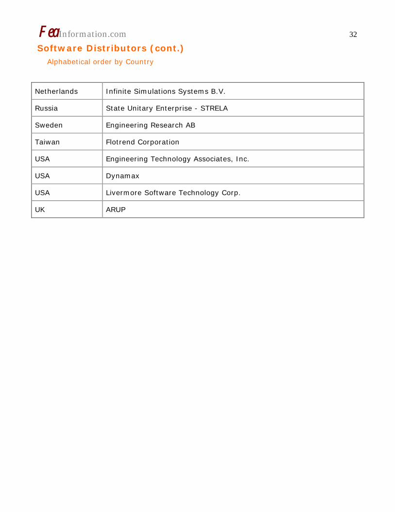
Software Distributors (cont.) Alphabetical order by Country
Netherlands Infinite Simulations Systems B.V.
Russia State Unitary Enterprise - STRELA
Sweden Engineering Research AB
Taiwan Flotrend Corporation
USA Engineering Technology Associates, Inc.
USA Dynamax
USA Livermore Software Technology Corp.
UK ARUP

FeaInformation.com 33
International Consulting and Engineering Services (continued on next page) Alphabetical Order By Country
Australia
Manly, NSW
Leading Engineering Analysis Providers (LEAP)
Greg Horner [email protected]
02 8966 7888
Canada
Kingston, Ontario
Metal Forming Analysis Corp.
Chris Galbraith [email protected]
(613) 547-5395
Germany Alzenau
CARHS.
49 6023 96 40 60
India
Bangalore
Altair Engineering India
Nelson Dias [email protected]
91 (0)80 2658-8540
Italy
Firenze
EnginSoft Spa
39 055 432010
UK
Solihull, West Midlands
ARUP
Brian Walker [email protected]
44 (0) 121 213 3317
FeaInformation.com 34
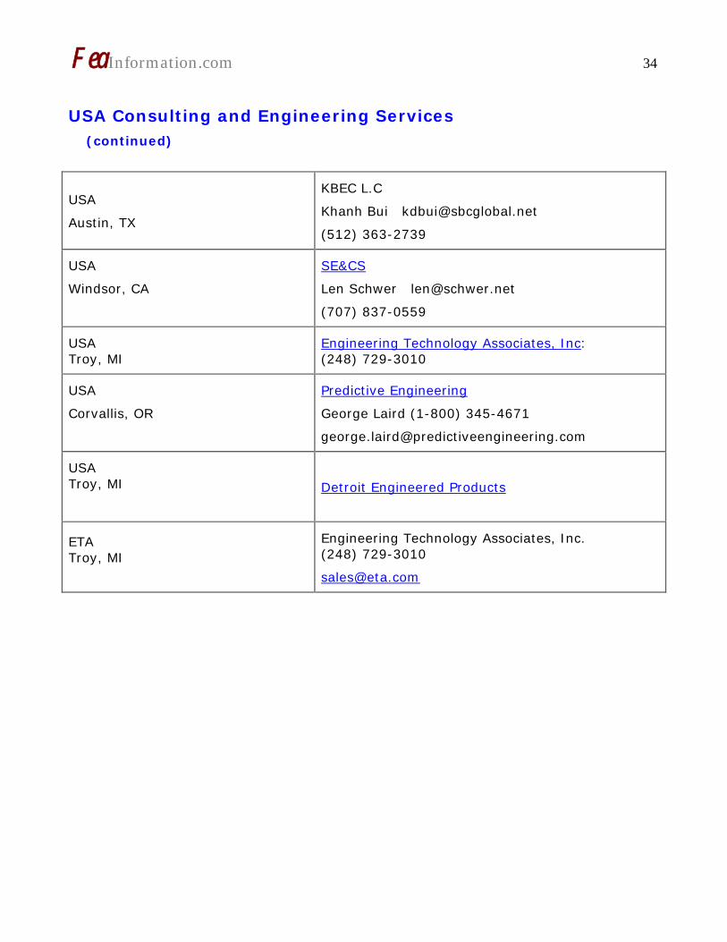
USA Consulting and Engineering Services (continued)
USA
Austin, TX
KBEC L.C
Khanh Bui [email protected]
(512) 363-2739
USA
Windsor, CA
SE&CS
Len Schwer [email protected]
(707) 837-0559
USA Troy, MI
Engineering Technology Associates, Inc: (248) 729-3010
USA
Corvallis, OR
Predictive Engineering
George Laird (1-800) 345-4671
USA Troy, MI
Detroit Engineered Products
ETA Troy, MI
Engineering Technology Associates, Inc. (248) 729-3010

FeaInformation.com 35
Educational & Contributing Participants Alphabetical Order By Country
China
Dr. Qing Zhou Tsinghua University
India
Dr. Anindya Deb Indian Institute of Science
Italy
Professor Gennaro Monacelli
Prode – Elasis & Univ. of Napoli, Frederico II
Russia Dr. Alexey I. Borovkov St. Petersburg State Tech. University
USA Dr. Ted Belytschko Northwestern University
USA Dr. David Benson University of California – San Diego
USA Dr. Bhavin V. Mehta Ohio University
USA Dr. Taylan Altan The Ohio State U – ERC/NSM
USA Dr. Ala Tabiei University of Cincinnati

FeaInformation.com 37
Informational Websites The LSTC LS-DYNA Support site: www.dynasupport.com
LSTC/DYNAmore LS-DYNA Support Site
FEA Informationwebsites
LSTC/DYNAmore S-DYNA Examples (more than 100 Examples)
LS-DYNA Conference Site
TopCrunch – Benchmarks
LS-DYNA Publications to Download On Line
LS-DYNA Publications
LSTC LS-PrePost Tutorials
CADFEM GmbH Portal
FeaInformation.com 38
New Intel Products Simplify and Speed Software Development for Multi-Core Processors
SANTA CLARA, Calif., June 5, 2007 – Intel Corporation today announced the availability of two software products that help developers efficiently create more reliable, high-performing applications that speed up a computer's responsiveness. The Intel® C++ Compiler and Fortran Professional Editions bring together a unique combination of highly optimizing compilers, performance libraries and the Intel® Threading Building Blocks.
The products feature new automatic support for accelerating program performance on Intel's latest multi-core processors. Applications containing 3-D graphics or video are automatically accelerated through the use of vectors via Streaming SIMD Extensions (SSE), including the latest SSE 4 instructions. Application performance is also accelerated by multi-core processors through the use of multiple threads. Combining the use of vectors and threads and integrating them with a technology known as loop transformation generates greater performance on multi-core processors without requiring developers to rewrite their code.
"Combining these capabilities in a cooperative and coordinated manner brings our customers added performance benefits and compiler reliability, which in turn gives greater PC responsiveness for gamers and everyday PC users," said Kevin J. Smith, director of the Intel Compiler Products. "This project has undergone extensive validation and application testing with Intel customers and we're excited about the results our
customers are seeing in their applications."
The combined capabilities also provide benefits that extend beyond multi-core optimizations by assisting developers in locating vulnerabilities that would otherwise go undetected, such as uninitialized variables and possible buffer overruns.
The Intel® C++ Professional Edition for Windows*, Linux* and Mac OS* X combines the Intel compiler with the Intel® Math Kernel Library, the Intel® Integrated Performance Primitives and the Intel® Threading Building Blocks.
The Intel Fortran Compiler Professional Edition for Windows, Linux and Mac OS X combines the Intel compiler with the Intel Math Kernel Library. For the first time, the Intel® Visual Fortran Compiler 10.0 now includes Microsoft Visual Studio, which provides the visual development environment to create, edit, build and debug Fortran applications.
The new products are all available today with suggested prices ranging from $599 to $1,599. Upgrades to the Professional Editions from the prior version of Intel compilers or libraries are available for limited time through resellers worldwide.
Intel also announced a new package for students that include all of these products as well as Intel® VTune Performance Analyzer, Intel® Thread Checker and Intel® Thread Profiler in one discounted package for students who qualify.

FeaInformation.com 39 Intel® Software provides resources, technologies, products and services developers need to create innovative products and industry-leading software solutions with enhanced business value and are designed to run best on Intel platforms. For more information, visit www.intel.com/software/products.
About Intel
Intel, the world leader in silicon innovation, develops technologies,
products and initiatives to continually advance how people work and live. Additional information about Intel is available at www.intel.com/pressroom.
Intel and the Intel logo are trademarks of Intel Corporation in the United States and other countries.
* Other brands may be claimed as the property of others.

FeaInformation.com 40
IBM Unleashes World's Fastest Chip in Powerful New Computer EXCERPT – COMPLETE ARTICLE
Processor doubles speed without adding to energy 'footprint,' enabling customers to reduce electricity consumption by almost half; Enough bandwidth to download entire iTunes catalog in 60 seconds
LONDON, UNITED KINGDOM - 21 May 2007: IBM (NYSE: IBM) today simultaneously launched the fastest microprocessor ever built and an ultra-powerful new computer server that leverages the chip’s many breakthroughs in energy conservation and virtualization technology. The new server is the first ever to hold all four major benchmark speed records for business and technical performance (1).
At 4.7 GHz, the dual-core POWER6™ processor doubles the speed of the previous generation POWER5™ while using nearly the same amount of electricity to run and cool it. This means customers can use the new processor to either increase their performance by 100 percent or cut their power consumption virtually in half.
But the new server offers more than just raw performance – it is the world’s most powerful midrange consolidation machine, containing special hardware and software that allows it to create many “virtual” servers on a single box.
IBM calculates that 30 SunFire v890s can be consolidated into a single rack of the new IBM machine, saving more than $100,000 per year on energy costs (3).
Benchmark Grand Slam
Demonstrating its remarkable versatility, the new IBM System p 570, running the POWER6 processor, claims the No.1 spots in the four most widely used performance benchmarks for Unix servers – SPECint2006 (measuring integer-calculating speed common in business applications), SPECfp2006 (measuring
floating point-calculating speed required for scientific applications), SPECjbb2005 (measuring Java™ performance in business operations per second) and TPC-C (measuring transaction processing capability) (1). This is the first time that a single system has owned all four categories. The new System p 570 now holds 25 benchmark records across a broad portfolio of business and technical applications (5).
The performance leadership is largely attributed the system’s balanced design. Unlike competing servers, IBM succeeded in scaling the new server’s processor performance and system design (cache sizes and bandwidth) in a balanced way. The POWER6 chip has a total cache size of 8MB per chip – four times the POWER5 chip – to keep pace with the awesome processor bandwidth. By contrast, many other servers concentrate mainly on processor performance, at the expense of the server’s ability to feed data to the chip at a rate that takes advantage of the processor’s speed.
“Like the victory of IBM’s Deep Blue chess-playing supercomputer 10 years ago this month, the debut of POWER6 processor-based systems proves that relentless innovation brings ‘impossible’ goals within reach,” said Bill Zeitler, senior vice president, IBM Systems and Technology Group. “The POWER6 processor forges blazing performance and energy conservation technologies into a single piece of silicon, driving unprecedented business value for our customers.”

FeaInformation.com 41 The POWER6 Chip: a Convention-Shattering Design
The POWER6 chip in the new IBM System p™ 570 server owns a number of industry “firsts.” It is the first UNIX microprocessor able to calculate decimal floating point arithmetic in hardware. Until now, calculations involving decimal numbers with floating decimal points were done using software. The built-in decimal floating point capability gives tremendous advantage to enterprises running complex tax, financial and ERP programs.
The POWER6 processor is built using IBM’s state-of-the-art 65 nanometer process technology. Coming at a time when some experts have predicted an end to Moore’s Law, which holds that processor speed doubles every 18 months, the IBM breakthrough is driven by a host of technical achievements scored during the five-year research and development effort to develop the POWER6 chip. These include:
A dramatic improvement in the way instructions are executed inside the chip. IBM scientists increased chip performance by keeping static the number of pipeline stages – the chunks of operations that must be completed in a single cycle of clock time -- but making each stage faster, removing unnecessary work and doing more in parallel. As a result, execution time is cut in half or energy consumption is reduced.
Separating circuits that can’t support low voltage operation onto their own power supply “rails,” allowing IBM to dramatically reduce power for the rest of the chip.
Voltage/frequency “slewing,” enabling the chip to lower electricity consumption by up to 50 percent, with minimal performance impact.
A new method of chip design that enables POWER6 to operate at low voltages, allowing the same chip to be used in low
power blade environments as well as large, high-performance symmetric multiprocessing machines. The chip has configurable bandwidth, enabling customers to choose maximum performance or minimal cost.
The POWER6 chip includes additional techniques to conserve power and reduce heat generated by POWER6 processor-based servers. Processor clocks can be dynamically turned off when there is no useful work to be done and turned back on when there are instructions to be executed.
Power saving is also realized when the memory is not fully utilized, as power to parts of the memory not being utilized is dynamically turned off and then turned back on when needed. In cases where an over-temperature condition is detected, the POWER6 chip can reduce the rate of instruction execution to remain within an acceptable, user-defined temperature envelope.
IBM plans to introduce the POWER6 chip throughout the System p and System i server lines.
World’s first UNIX server with active virtual machine mobility
Also announced today, IBM is unveiling an industry-first with a new feature that provides customers with the ability to move live virtual machines from one physical UNIX server to another while maintaining continuous availability. Coined the POWER6 Live Partition Mobility function, this technology -- currently in beta, with general availability planned for later this year -- enables customers to move active virtualized partitions without temporarily suspending them. While competing offerings require a disruptive reboot of the UNIX system and software stack, IBM is the first vendor to help clients optimize resource utilization on a broader scale by allowing administrators
FeaInformation.com 42 to think of large groups of servers as a fluid resource rather than focusing on each server as a single entity with a dedicated purpose.
On the services front, IBM Global Technology Services announced implementation, migration & assessment
service products that help clients shorten the time required to plan, implement and integrate new System p POWER6 processor-based servers into their production environment.
For more information, please visit www.ibm.com.
IBM is a trademark of IBM Corporation in the United States and/or other countries. All other company/product names and service marks may be trademarks or registered trademarks of their respective companies. UNIX is a registered trademark in the United States and other countries licensed exclusively through The Open Group.
TPC-C is a trademark of the Transaction Processing Performance Council. SPEC and the benchmark names SPECint. SPECfp, and SPECjbb are registered trademarks of the Standard Performance Evaluation Corporation. Java and all Java-based trademarks and logos are trademarks of Sun Microsystems, Inc. in the United States and/or other countries.
All statements regarding IBM's future direction and intent are subject to change or withdrawal without notice, and represent goals and objectives only.
IBM results to be submitted by 5/21/07. All competitive benchmark results current as of 5/18/07.
Sources: http://www.tpc.org, http://www.spec.org
Contact(s) information
John BuscemiIBM Media Relations914-766-4495 [email protected]
Vince SmithIBM Media Relations44-1962-815266 [email protected]