fea information news sept2003 - dynalook...in 2002's spirit: stallion of the cimarron,...
TRANSCRIPT

September 2003

2
Leaders in Cutting Edge Technology
Software, Hardware and Services for The Engineering Community
LEAP
Australia Altair
Western Region US DYNAMAX
US Cril Technology
Simulation France
GISSETA
India MFAC Canada
DYNAmore Germany
Flotrend Taiwan
KOSTECH
Korea ERAB Sweden
THEME Korea
ALTAIR Italy
CAD-FEM Germany
Numerica SRL Italy
ANSYS China
Educational Participants and Contributing Authors Dr. Ted. Belytschko
US Dr. Bhavin V. Mehta
US Dr. Taylan Altan
US Dr. David Benson
US
Dr. Alexey L. Borovkov
Russia
Prof. Gennaro Monacelli
Italy
Prof. Ala Tabiei US
Tony Taylor US

3
Articles
04 ANSYS: Leading Motorsport Team Races to Get Car Design Right First Time 07 HP: DreamWorks and hp making waves in the world of digital animation 10 First Call for Papers – 8th International LS-DYNA Users Conference 11 Website Showcase: ETA Fujitsu 12 FEA Information Participants 13 Special Announcements – News Page Highlights - Events Presentation Ala Tabiei
Jin Wu
Editor Trent Eggleston Editor – Technical Content Arthur B. Shapiro Technical Writer Dr. David Benson Technical Writer Uli Franz Graphic Designer Wayne Mindle Feature Director Marsha J. Victory
The contents of this publication is deemed to be accurate and complete. However, FEA Information Inc. doesn’t guarantee or warranty accuracy or completeness of the material contained herein. All trademarks are the property of their respective owners. This publication is published for FEA Information Inc., copyright 2003. All rights reserved. Not to be reproduced in hardcopy or electronic copy. Note: All reprinted full articles, excerpts, notations, and other matter are reprinted with permission and full copyright remains with the original author or company designated in the copyright notice
4
Leading Motorsport Team Races to Get Car Design Right First Time © Copyright ANSYS Inc.
http://www.ansys.com/customer_stories/case_studies/automotive_penske.htm Penske - Challenge: To design a racecar that meets the stringent criteria and tight deadlines of the Indy Racing League Solution: Use ANSYS® to analyze changes during the design phase of product development Benefits:
• Able to make early, intelligent decisions about design, including materials and manufacturing
• Able to stiffen an upright by 25 percent without increasing weight Introduction: Next to Mario Andretti, there is, perhaps, no more recognizable name in American motorsports than Roger Penske - racing and winning in the U.S. since 1958. After 45 years of racing, Team Penske embarked on a new and exciting challenge. With 115 Indy car wins, including a record 12 Indy 500 victories, Team Penske entered the Indy Racing League (IRL) on a full time basis. This meant competing with different equipment on 15 different tracks. Moving to the IRL presented a challenge not just to the team on the track, but also to Penske’s design team in Poole, Dorset, the company’s traditional home base. Technical Director Nigel Beresford leads the eight-strong design team, which combines a healthy mix of recent graduates and experienced racecar designers. They now have to operate under a new set of stringent rules that govern the construction on cars competing in the IRL.
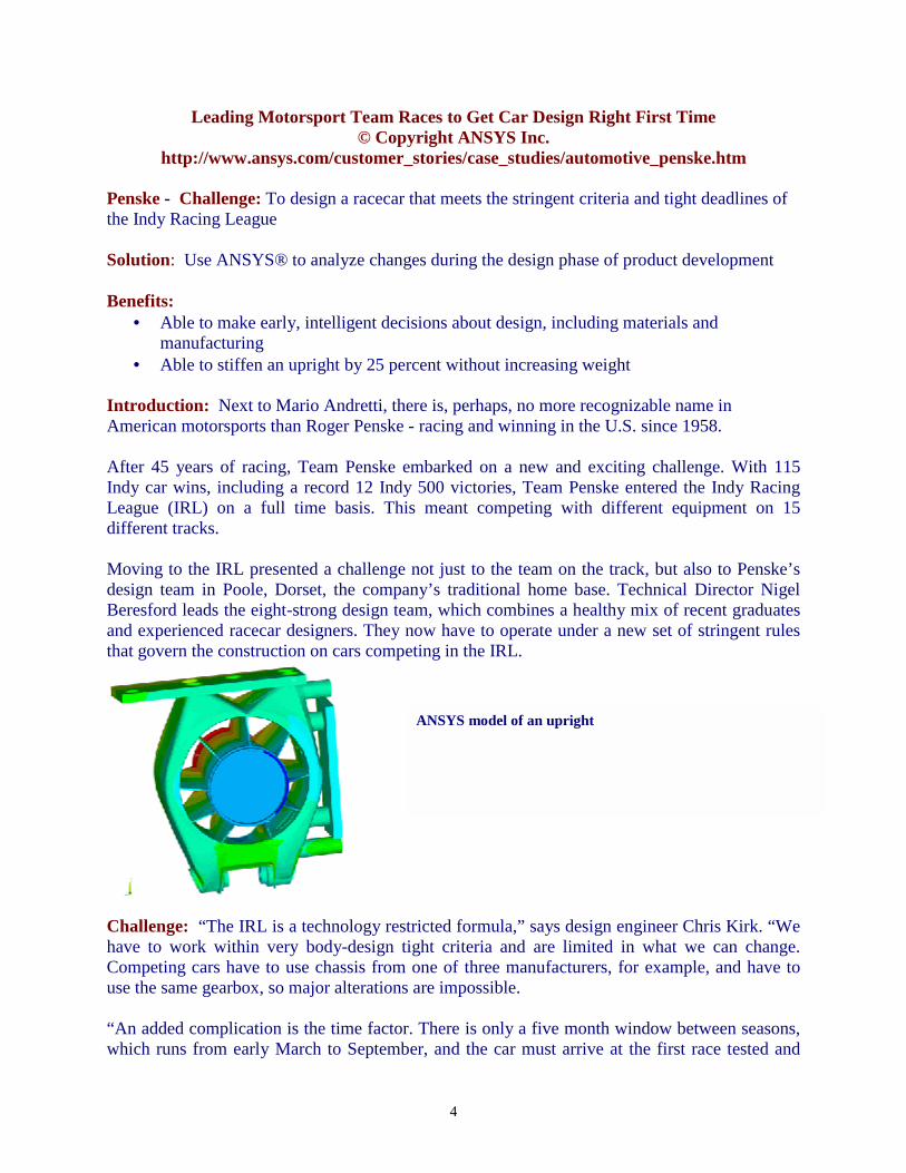
Challenge: “The IRL is a technology restricted formula,” says design engineer Chris Kirk. “We have to work within very body-design tight criteria and are limited in what we can change. Competing cars have to use chassis from one of three manufacturers, for example, and have to use the same gearbox, so major alterations are impossible. “An added complication is the time factor. There is only a five month window between seasons, which runs from early March to September, and the car must arrive at the first race tested and
ANSYS model of an upright

5
ready to win. Prior to the first season in 2001, for example, we built a new wind tunnel model of the chassis in just six weeks. “Even during the five-month off-season we are very restricted in the design changes we can make. Cars have to be ready by January for testing, so we cannot analyze every single part of the car each season,” said Kirk. “We have no time for back-up plans or mistakes. We have to get it right the first time to give the team optimum performance.” Solution: The design team uses Pro/ENGINEER as their primary design program running on HP C3700 hardware with ANSYS finite element analysis (FEA) for testing design changes. ANSYS significantly shortens time-to-market by allowing engineers to utilize basic analysis capabilities during the design phase of product or part development. The program provides designers with access to the same underlying analysis techniques that will be deployed later for detailed product certification, enabling them to make early, intelligent decisions about design, materials, and manufacturing. Using ANSYS, the racecar is broken down into many small simple blocks known as elements. The behavior of each individual element is described with a relatively simple set of equations. Just as the set of elements would be joined together to build the final product, the equations describing the behaviors of the individual elements are joined into an extremely large set of simultaneous equations that describe the end product’s behavior. The software then is used to solve this large set of simultaneous equations. From this solution, FEA software can extract the behavior of the individual elements. This method is the only proven way to deal with complex boundaries and provides efficient solutions to “real world” physics-based problems. FEA provides a way to deal with engineering problems that are more complex than can be dealt with analytically using partial differential equations. In the absence of FEA, engineers must rely on hand calculations. For complex designs, such as a racecar, the simplifying assumptions required to make any calculations can lead to over- built or heavy end products. In addition, hand calculations require the building of prototypes and field tests. These field tests may involve expensive strain gauging to evaluate strength and deformation. ANSYS uses precise equations, which can help to minimize the weight of a design. Since the expected loads have already been assigned to the design on a computer, there is a reduction in the number of prototypes that need to be built. Field tests are then used to establish the loading on structures, which is then used to make future design improvements via FEA.
Benefits: “Because of IRL rules, we are limited to changes on the suspension and the aerodynamic area in front of the rear wheels. A number of minor changes can each give tiny
With 12 Indianapolis 500 wins, Penske Racing is the most successful Indy car racing team in history.

6
benefits, which together can make all the difference to the car’s performance,” said Kirk. “The cars race for several hours and often cross the finish line within hundredths of a second of each other so tiny speed advantages can make big differences to race results. For example, we designed a new upright, which has to be both light and stiff and can significantly affect performance. “Over a week, we built an ANSYS model using solid and shell elements, and the testing highlighted an area of the upright that was over flexing. We were able to redesign the upright (a suspension component), which when it was retested was 25 percent stiffer for the same weight. This dramatically improves the feedback that the driver gets from the steering wheel and provides the information to help him drive more effectively.” Penske also uses ANSYS for composite analysis. A considerable problem from a composite FEA point of view is the increased amount of data involved, due to the ply lay-ups, versus normal homogeneous material models. ANSYS provides the user with a number of easy-to-use tools for firstly checking the validity of the composite material modeling used, and secondly helping the user to evaluate the results through the composite lay-up that are of importance. Nonlinear material behavior and material failure models can also be used to evaluate problems in the composite design. Kirk continues, “The way we lay-up composites can be a powerful way of effecting performance and we find that ANSYS handles them all in a very user friendly way and, using IGES, we can transfer the data between ANSYS and Pro/ENGINEER faultlessly.” Once the ANSYS model is constructed, we can alter the ply layups quickly to find the optimum. It is not commonly known that there are many different types of carbon fibers, different weaves in the cloth, and resin systems to bind them. The engineers can quantify the effects and recommend the best layup for a given part. For aerodynamic pieces, the team can find the loads, which the part will experience from wind tunnel testing. They also must abide by the rules, which prevent excessively flexible parts being used to gain an advantage. Under IRL rules, constructors use the same chassis for three years, therefore, at the end of the 2005 season; Penske will have to start all over again with a new wind tunnel model and testing program. Still, if they maintain Roger Penske’s philosophy that “Effort Equals Results” then their first IRL Championship can’t be far away. ANSYS Inc. Copyright ANSYS is a registered trademark and DesignSpace is a registered trademark of SAS IP, Inc., a wholly owned subsidiary of ANSYS Inc. All other trademarks and registered trademarks are the property of their respective owners.

7
DreamWorks and hp making waves in the world of digital animation
© Copyright – reprinted with permission http://www.hp.com/hpinfo/newsroom/feature_stories/2003/03sinbad.html
Sinbad: Legend of the Seven Seas™ & © 2003 DreamWorks L.L.C.
by Susan Twombly
Jul. 2003 -- This week, DreamWorks sets sail on a new voyage that's bound for theaters. Sinbad — Legend of the Seven Seas follows the tale of the most daring and notorious rogue ever to sail the seven seas.
For DreamWorks artists, bringing Sinbad to the screen meant pushing the limits of their own world, well past conventional animation to a place where talent and technology combine to create richer, more detailed images. From wind-swept waters to perilous mountain peaks to the surf-soaked sea monsters that round out a cast of characters far outnumbering that of any DreamWorks feature before it.
But details and sea demons devour a lot of compute power — an appetite matched only by that of the DreamWorks artistic staff, who constantly crave more from technology.
Linux-based HP solutions deliver that power. In fact, Sinbad is the first DreamWorks feature created entirely on Linux systems. A Linux-based computer farm, known as a "rendering farm," creates film-quality images from files created on workstations on animators' desks — helping to make dreams work at DreamWorks.
In Sinbad, DreamWorks and HP pushed technology boundaries by combining traditional hand-drawn 2D images with 3D computer graphics to create what DreamWorks co-founder Jeffrey Katzenberg calls "tradigital" animation."
For Sinbad, that meant enabling a real-time, interactive union between artist and technology that forever changed the creative process.

8
keeping the creative flow
This is the third DreamWorks feature where HP Linux systems played a lead role. In the final stage of the Shrek production, Linux-based servers were deployed to provide the extra computing horsepower to complete the final rendering for the film.
In 2002's Spirit: Stallion of the Cimarron, industry-standard HP workstations provided the horsepower needed to bring Linux-driven graphics capabilities to the desktop. In doing so, DreamWorks and HP pushed technology boundaries by combining traditional hand-drawn 2D
images with 3D computer graphics to create what DreamWorks co-founder Jeffrey Katzenberg calls "tradigital" animation.
That revolution continued with Sinbad. Talented artists hand drew the main characters with pencil and paper. But the traditional method essentially stopped there, as these drawings were scanned into the computer, combined with computer graphic elements, and manipulated with DreamWorks' proprietary ToonShooter application. Animators adjusted the timing, synchronized the animation with sound and then played the sequences back at film speed — 24 frames per second. During Spirit, HP Linux workstations had the power to play animation back at this speed — exactly how audiences would view it — preserving the artist's vision.
During Sinbad's production, system speed and power played an equally important role. Previous computer work, necessary for the creation of digital water, was done in "batch mode," requiring artists to submit a job, then return several minutes later to view results. With HP Linux servers and workstations on the back and front end, artists no longer waited for proprietary UNIX-based systems to respond. Working in near real time, they maintained the creative flow and increased the number of iterations for particular details — improving the artistic quality of the film.
After "toon shooting," artists digitally painted each frame on HP Workstations, equipped with dual monitors and drawing tablets with pressure-sensitive pens. A full pallet of colors and drawing tools appeared on one screen, with images on another to create the digital effects that make Sinbad's journey jump off the screen.
DreamWorks also relied on commercial animation software applications, including Alias|Wavefront's MAYA, to create much of the 3D animation for Sinbad. The special effects, sea monsters, lighting effects and many other components were created in MAYA and blended with hand-animated 2D characters to create the unique look and feel of Sinbad.
DreamWorks animator at work on Sinbad

9
making a splash
Even with advancements in computer graphics, animating water is still a tremendous challenge. This requires tremendous compute power — power that was essential to handle the complex fluid physics that make up Sinbad's seven seas. With nearly all of the feature taking place on or near water, Sinbad's aquatic effects had to be great.
In response, DreamWorks created custom software to help animate water. Running on HP workstations, this custom software was used to create realistic wave motion, the splashes, whitewater and mists within the feature's wet world. Near real-time processes allowed artists to work more interactively with the animation they created. Artists quickly made changes, with no interruption in the flow of water, or ideas.
Likewise, a custom animation review tool, running on HP workstations, delivered real-time digital dailies for on-the-spot editing and instant collaboration between production and creative teams.
All this speeds the production cycle. Ed Leonard, Head of Animation Technology at DreamWorks, says artists pour that extra time back into the creative process. "With real-time interaction, artists get immediate feedback and work becomes a more iterative process," he says. "We have more time to explore creative possibilities."
Sinbad: Legend of the Seven Seas™ & © 2003 DreamWorks L.L.C.
At DreamWorks, Linux-based HP systems help to create the surf and sea monsters that make Sinbad's journey jump off the screen.

10
First Call For Papers
Conference Papers: The first named author of each accepted paper will receive a free admission to the conference if the author registers at the hotel under LSTC Conference registration. Application Areas Being Accepted for Paper Submission:
• Aerospace • Occupant Safety • Impact and Drop Testing • Ballistic and Penetration • Seismic Engineering • Modeling Techniques
• Civil Engineering • Transportation • Nuclear Applications • Manufacturing Processes • Metal Forming • Ship Building • Automotive Crashworthiness • Biomechanics • Virtual Proving Ground
Abstract Length: Approx. 300 words, please include figures, if possible Paper Length: Maximum of 3,000 words, single-spaced, on 8-1/2” x 11” paper Format: A MS Word template will be provided Contact for papers: [email protected] _______________________________________________________________________________
Livermore Software Technology Corp. (925) 449-2500 www.lstc.com
Engineering Technology Associates (248) 729-3010 www.eta.com
The 8th International LS-DYNA Users Conference
May 2 – 4th, 2004 To be held at:
The Hyatt Regency Dearborn Hotel & Conference Center, Fairlane Town Center, Dearborn, MI
Co-Hosted by:
Livermore Software Technology Corp. (LSTC) Engineering Technology Associates (ETA)
Abstract Deadline: December 5, 2003 email your abstract to: [email protected] Notification: January 10, 2004 Paper Deadline: March 05, 2004 Inquiries: [email protected]
11
Participant Website Showcase
Engineering Technology Associates, Inc. www.eta.com
Fujitsu – Partial Site View – please visit www.fujitsu.com
12
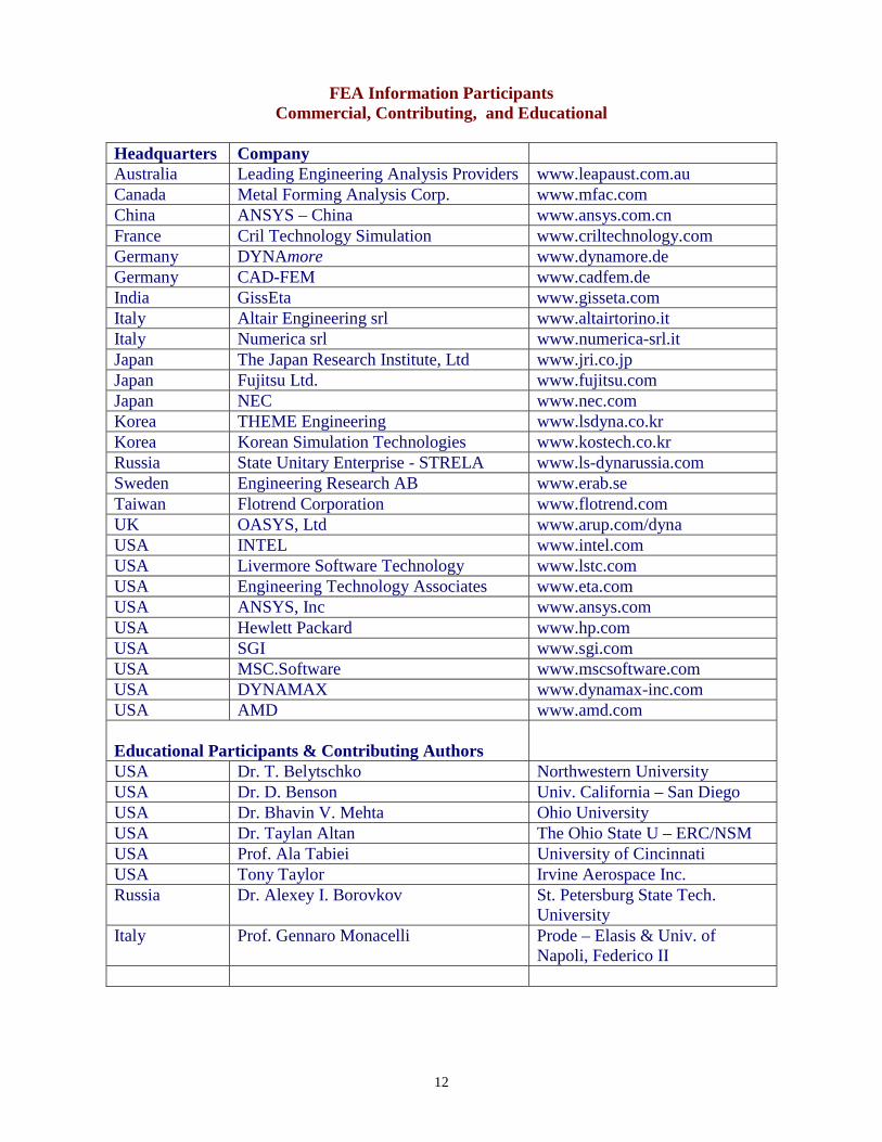
FEA Information Participants Commercial, Contributing, and Educational
Headquarters Company Australia Leading Engineering Analysis Providers www.leapaust.com.au Canada Metal Forming Analysis Corp. www.mfac.com China ANSYS – China www.ansys.com.cn France Cril Technology Simulation www.criltechnology.com Germany DYNAmore www.dynamore.de Germany CAD-FEM www.cadfem.de India GissEta www.gisseta.com Italy Altair Engineering srl www.altairtorino.it Italy Numerica srl www.numerica-srl.it Japan The Japan Research Institute, Ltd www.jri.co.jp Japan Fujitsu Ltd. www.fujitsu.com Japan NEC www.nec.com Korea THEME Engineering www.lsdyna.co.kr Korea Korean Simulation Technologies www.kostech.co.kr Russia State Unitary Enterprise - STRELA www.ls-dynarussia.com Sweden Engineering Research AB www.erab.se Taiwan Flotrend Corporation www.flotrend.com UK OASYS, Ltd www.arup.com/dyna USA INTEL www.intel.com USA Livermore Software Technology www.lstc.com USA Engineering Technology Associates www.eta.com USA ANSYS, Inc www.ansys.com USA Hewlett Packard www.hp.com USA SGI www.sgi.com USA MSC.Software www.mscsoftware.com USA DYNAMAX www.dynamax-inc.com USA AMD www.amd.com Educational Participants & Contributing Authors
USA Dr. T. Belytschko Northwestern University USA Dr. D. Benson Univ. California – San Diego USA Dr. Bhavin V. Mehta Ohio University USA Dr. Taylan Altan The Ohio State U – ERC/NSM USA Prof. Ala Tabiei University of Cincinnati USA Tony Taylor Irvine Aerospace Inc. Russia Dr. Alexey I. Borovkov St. Petersburg State Tech.
University Italy Prof. Gennaro Monacelli Prode – Elasis & Univ. of
Napoli, Federico II
13
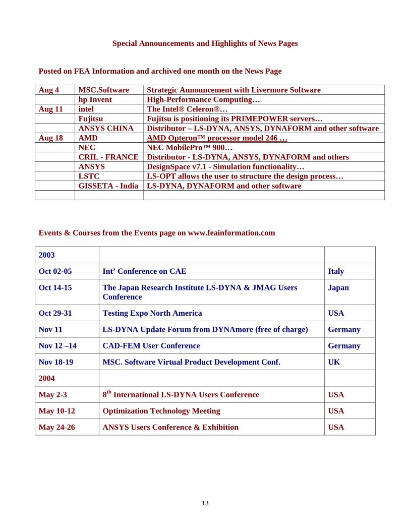
Special Announcements and Highlights of News Pages
Posted on FEA Information and archived one month on the News Page Aug 4 MSC.Software Strategic Announcement with Livermore Software hp Invent High-Performance Computing… Aug 11 intel The Intel® Celeron®… Fujitsu Fujitsu is positioning its PRIMEPOWER servers… ANSYS CHINA Distributor – LS-DYNA, ANSYS, DYNAFORM and other software Aug 18 AMD AMD Opteron™ processor model 246 … NEC NEC MobilePro™ 900… CRIL - FRANCE Distributor - LS-DYNA, ANSYS, DYNAFORM and others ANSYS DesignSpace v7.1 - Simulation functionality… LSTC LS-OPT allows the user to structure the design process… GISSETA - India LS-DYNA, DYNAFORM and other software
Events & Courses from the Events page on www.feainformation.com
2003
Oct 02-05 Int’ Conference on CAE Italy
Oct 14-15 The Japan Research Institute LS-DYNA & JMAG Users Conference
Japan
Oct 29-31 Testing Expo North America USA
Nov 11 LS-DYNA Update Forum from DYNAmore (free of charge) Germany
Nov 12 –14 CAD-FEM User Conference Germany
Nov 18-19 MSC. Software Virtual Product Development Conf. UK
2004
May 2-3 8th International LS-DYNA Users Conference USA
May 10-12 Optimization Technology Meeting USA
May 24-26 ANSYS Users Conference & Exhibition USA

112
DEVELOPMENT OF THE DYNA3D SIMULATION CODE WITH AUTOMATED FRACTURE PROCEDURE FOR 3-D BRICK ELEMENTS
Ala Tabiei and Jin Wu
THE CENTER OF EXCELLENCE IN DYNA3D ANALYSIS Department of Aerospace Eng. & Eng. Mechanics
University of Cincinnati, Cincinnati, OH 45221-0070 [email protected]
http://www.ase.uc.edu/~atabiei/activity.html
ABSTRACT Numerical simulation of cracked structures is an important aspect in structural safety assessment. In recent years, there has been an increasing rate of development of numerical codes for modeling fracture procedure. The subject of this investigation is implementing automated fracture models in the DYNA3D nonlinear explicit finite element code to simulate pseudo 3-D crack growth procedure. The implemented models have the capabilities of simulating automatic crack propagation without user intervention. The implementation is carried on solid elements. The methodology of implementing fracture models is described. An element deletion-and-replacement remeshing procedure is proposed for updating the explicit geometric description of evolving cracks. Fracture parameters such as stress intensity factors, energy release rates and crack tip opening angle are evaluated. The maximum circumferential stress criterion is utilized to predict the direction of crack advancement. Seven crack problems are presented to verify the effectiveness of the methodology. Mesh sensitivity and loading rate effects are studied in the validation of the presented procedure.
METHODOLOGY OF IMPLEMENTING 3-D FRACTURE MODELS In this study, fracture models have been implemented in the DYNA3D code for 3-D crack growth simulations. The implemented fracture models have the capabilities of simulating automatic crack propagation without user intervention. The implementation is carried on solid elements. The input phase subroutines of the DYNA3D code have been modified to read the crack input parameters and allocate memory for the fracture model arrays. A uniform crack growth with prediction of growth direction is implemented. Crack extension can be provoked by several different fracture parameters as follows: 1. The stress intensity factors (KI, KII and KIII) 2. Energy release rates (GI, GII and GIII) and 3. Crack tip opening angle (CTOA). The maximum circumferential stress criterion is utilized to predict the growth direction. An element-stress based failure methodology is also provided. Similar to the conventional smeared crack approaches, the critical fracture tensile stress is used for activation of crack growth. The crack opening profile, however, is simulated here

113
explicitly. The crack propagates in the direction perpendicular to the maximum principal stress. The implemented procedure can be used to simulate through thickness crack growth. The methodology of implementing the 3-D fracture models is described in the paper by the authors in the International Journal of Numerical Methods in Engineering 2003. Dynamic Crack Propagation Simulation of Interacting Cracks This is an interesting example for dynamic crack propagation simulation. The problem involves two interacting edge cracks in a sheet. The cracks at two sides of the sheet are slightly misaligned to provide initial asymmetry. During the crack propagation three stages can be detected: initially the cracks repel from each other, as growth continues, they attract. The final intersection of the two cracks results in the ejection of a small elliptical piece of material. This crack interaction phenomenon was experimentally observed by Sinha et al. (1986). To verify the effectiveness of current implementation of the fracture model, the dynamic propagation of two interacting cracks is simulated. The FE model (6480 elements and two layers through the thickness) is shown in Figure 5-14. Initially the two edge cracks are slightly inclined to provide asymmetry. A constant velocity is imposed on both ends of the plate for tension. The material properties of 2024-T3 aluminum alloy are employed for the simulation. The crack growth is controlled by the CTOA criterion. Figures 5-15 and 5-16 show the close-up views of the finite element mesh at different stages of crack propagation. At each crack growth step the geometry of the plate is automatically remeshed to generate new explicit crack opening profiles. The sequential growth steps are automatically determined by numerical solutions without user intervention. This example can be considered a rather severe test of current fracture model. As shown in Figures 5-15 and 5-16, current fracture model effectively captures the interaction of the two cracks: initial avoidance, later attraction and final separation.
Figure 5-1. FE model for a finite plate with two asymmetric cracks

114
(a) Initial propagation
(b) Crack avoidance
Figure 5-2. Dynamic crack propagation simulation of interacting cracks

115
(c) Crack attraction
(d) Final separation
Figure 5-3. Dynamic crack propagation simulation of interacting cracks (contined)

116
Crack Growth in a Cylindrical Pipe In this example, crack growth in a three dimensional curved surface is simulated by current fracture model. The FE model used in validation is shown in Figure 5-24. It is a 5.0 m long cylindrical pipe with the 1.422 m diameter and 1.87 mm wall thickness. A through thickness crack is inclined at 45 degrees from the longitudinal direction of the pipe. The FE model consists of 12855 nodes and 8452 elements with two element layers through the thickness. In this example, three different loading cases are considered here to predict the crack growth path and test current fracture model. The material properties of 2024-T3 aluminum alloy and the CTOA crack growth criterion are used herein. The simulation results from these cases indicate that current fracture model reasonably captures the expected behavior of the crack propagation. ! Pipe under Tensile Loading
In this case, a constant velocity is imposed on each end of the pipe for tension. The crack should propagate along the transverse direction of the pipe. Figure 5-25 (a-c) shows the simulation results at different stages of the crack growth. Initially, the crack grows along the transverse direction of the pipe as expected (see Figure 5-25a). As the crack growth continues, the crack tips begin to approach each other and the interaction occurs. The interaction causes the attraction of two crack tips and final separation of the pipe. Figure 5-25 (b-c) shows the frontal and back views of the final separation. The simulated phenomenon is similar to the crack growth behavior described in Section 5.4.4. ! Pipe under Pressure Loading
In this case, the cylindrical pipe is loaded with increasingly applied internal pressure. With the increase of pressure, the pipe swells and the crack should grow along the longitudinal direction of the pipe. Figure 5-26a shows the initial stage of the crack propagation. The initial crack growth path is exactly along the longitudinal direction as expected. As the crack extends and approaches the ends of the pipe, the crack propagation deviates slightly until final separation (see Figure 5-26b). ! Pipe under Torsion Loading
In this case, each end of the pipe is applied with a constant angular velocity to simulate the pipe torsion. On basis of macroscopic strength theory, the crack should propagate at 45 degrees from the transverse direction of the pipe. Figure 5-27 (a-b) shows the simulation results at the stages of initial propagation and final separation. The predicted crack growth path deviates from the 45-degree direction. This deviation mainly comes from the fracture theory used in current fracture model. In current fracture model, the maximum circumferential stress criterion is utilized in prediction of crack propagation direction. Based on this criterion, a crack under pure shear loading is assumed to grow with an initial propagation angle of 70°32’ rather than 45°.

117
Figure 5-4. FE model of a cylindrical pipe with an inclined crack
(a) Running crack
Figure 5-5. Crack growth in a pipe under tensile loading

118
(b) Final separation (frontal view)
(c) Final separation (back view)
Figure 5-25. Crack growth in a pipe under tensile loading

119
(a) Running crack
(b) Final separation
Figure 5-6. Crack growth in a pipe under pressure loading

120
(a) Running crack
(b) Final separation
Figure 5-7. Crack growth in a pipe under torsion loading

121
REFERENCES Tabiei, A. and Wu J., “DEVELOPMENT OF THE DYNA3D SIMULATION CODE WITH AUTOMATED FRACTURE PROCEDURE FOR 3-D BRICK ELEMENTS”, Vol 57, No. 13., Int. J. of Numerical Methods in Engineering, 2003.