fea simulations of magnets with grain oriented steel simulations of magnets with grain oriented...
TRANSCRIPT

BNL-98381-2012-IR
FEA Simulations of Magnets with Grain Oriented Steel
Holger Witte
August 2012
Physics Department
Brookhaven National Laboratory
U.S. Department of Energy Office of Science
Notice: This manuscript has been authored by employees of Brookhaven Science Associates, LLC under Contract No. DE-AC02-98CH10886 with the U.S. Department of Energy. The publisher by accepting the manuscript for publication acknowledges that the United States Government retains a non-exclusive, paid-up, irrevocable, world-wide license to publish or reproduce the published form of this manuscript, or allow others to do so, for United States Government purposes.

DISCLAIMER
This report was prepared as an account of work sponsored by an agency of the United States Government. Neither the United States Government nor any agency thereof, nor any of their employees, nor any of their contractors, subcontractors, or their employees, makes any warranty, express or implied, or assumes any legal liability or responsibility for the accuracy, completeness, or any third party’s use or the results of such use of any information, apparatus, product, or process disclosed, or represents that its use would not infringe privately owned rights. Reference herein to any specific commercial product, process, or service by trade name, trademark, manufacturer, or otherwise, does not necessarily constitute or imply its endorsement, recommendation, or favoring by the United States Government or any agency thereof or its contractors or subcontractors. The views and opinions of authors expressed herein do not necessarily state or reflect those of the United States Government or any agency thereof.

BNL-98381-2012-IR/79024
FEA Simulations of Magnets with GrainOriented Steel
Holger Witte∗
August 6, 2012
One of the potential successors of the Large Hadron Collider is a Muon Col-lider. Muons are short-lived particles, which therefore require fast acceleration.One potential avenue is a very fast cycling cyclotron, where the bending is sup-plied by a combination of fixed-field superconducting magnets and fast rampingnormal conducting iron-cored coils.Due to the high ramping rate (around 1 kHz) eddy current and hysteresis
losses are a concern. One way to overcome these is by using grain-orientedsoft-iron, which promises superior magnetic properties in the direction of thegrains.This note summarizes efforts to include the anisotropic material properties
of grain-oriented steel in finite element analysis to predict the behaviour of thedipole magnets for this accelerator.It was found that including anisotropic material properties has a detrimental
effect on model convergence. During this study it was not possible to includegrain oriented steel with an accuracy necessary to study the field quality of adipole magnet.
1 Introduction and Motivation
One potential successor of the Large Hadron Collider is a Muon Collider (1.5 TeV ormore). Muons are short-lived particles (around 2.2µs), which therefore need to be accel-erated quickly to their desired energy. A new type of synchrotron has been suggested [4],proposing to accelerate muons up to 750 GeV in the Tevatron tunnel. The lattice of thissynchrotron implies that the required bending of the particles is provided by a combination
∗Brookhaven National Laboratory, Bldg. 901A, PO Box 5000, Upton, NY, 11973, USA. EMail:[email protected]
1

BNL-98381-2012-IR/79024
of superconducting and normal conducting magnets (see Fig. 1 (a)). The 8 T supercon-ducting magnets supply a DC field, which is complemented by normal conducting ironcored coils supplying a magnetic field of ±1.8 T. This allows to tune the integral bendingpower to keep the bending radius constant.
Figure 1: Lattice of the fast cycling synchrotron (a) and test dipole magnet to demonstratefeasibility (b). The gap of the test magnet is 46× 46× 1.5 mm. The laminationswere cut with wire EDM. The wound coils use a 12 gauge copper wire. Themagnet is powered with a LC circuit with capacitor and IGBT switch (400V,4.1J and a peak current of 54A).
A drawback of this solution is that due to the rapid acceleration the iron-cored magnetsneed to be ramped equally fast, at a rate of about 1 kHz. This is higher by an order ofmagnitude in comparison to existing systems. A concern are eddy-current heating andmagnetization losses. To overcome this it was suggested to use grain-oriented Si-steel,which possesses superior magnetic properties in the preferred direction.A test magnet was built (see Fig. 1 (b)), but unfortunately it did not perform as expected.
One potential source of error is inaccurate modelling of the highly anisotropic soft-iron.The purpose of this report is to explore possible ways how to include the anisotropicmaterial properties in commercial finite element packages, to allow to identify potentialsources of error and to optimize the present design.
2 Simulation Details
2.1 Grain Oriented Steel
Grain oriented steel available from a number of manufacturers, e.g. ThyssenKrupp (Kurt-Schumacher-Str. 95, D-45881 Gelsenkirchen, Germany), AK Steel (AK Steel Corporation,West Chester, OH 45069, USA) or Thomas & Skinner (Indianapolis Offices, 1120 East23rd St., Indianapolis, IN 46206, USA). The manufacturers supply limited informationabout their products, which indicate that the magnetic properties are extremely good if
2
BNL-98381-2012-IR/79024
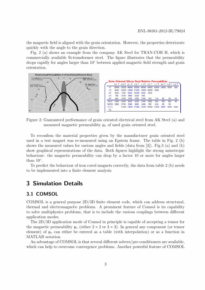
the magnetic field is aligned with the grain orientation. However, the properties deterioratequickly with the angle to the grain direction.Fig. 2 (a) shows an example from the company AK Steel for TRAN-COR H, which is
commercially available Si-transformer steel. The figure illustrates that the permeabilitydrops rapidly for angles larger than 10◦ between applied magnetic field strength and grainorientation.
Figure 2: Guaranteed performance of grain oriented electrical steel from AK Steel (a) andmeasured magnetic permeability µr of used grain oriented steel.
To reconfirm the material properties given by the manufacturer grain oriented steelused in a test magnet was re-measured using an Epstein frame. The table in Fig. 2 (b)shows the measured values for various angles and fields (data from [3]). Fig.3 (a) and (b)show graphical representations of the data. Both figures highlight the strong anisotropicbehaviour: the magnetic permeability can drop by a factor 10 or more for angles largerthan 10◦.To predict the behaviour of iron cored magnets correctly, the data from table 2 (b) needs
to be implemented into a finite element analysis.
3 Simulation Details
3.1 COMSOL
COMSOL is a general purpose 2D/3D finite element code, which can address structural,thermal and electromagnetic problems. A prominent feature of Comsol is its capabilityto solve multiphysics problems, that is to include the various couplings between differentapplication modes.The 2D/3D application mode of Comsol in principle is capable of accepting a tensor for
the magnetic permeability µr (either 2× 2 or 3× 3). In general any component (or tensorelement) of µr can either be entered as a table (with interpolation) or as a function inMATLAB notation.An advantage of COMSOL is that several different solvers/pre-conditioners are available,
which can help to overcome convergence problems. Another powerful feature of COMSOL
3

BNL-98381-2012-IR/79024
Figure 3: Magnetic permeability of grain oriented steel up to 1.7 T for various anglesbetween the grain orientation and the applied field strength (a) and polar plotof the magnetic permeability of grain oriented steel for 1.0 and 1.5 T (b). Forillustrative purposes isotropic material is also shown.
is that generic ODEs can be solved.
3.2 VectorFields/Cobham Opera
Opera is a 2D/3D1 finite element package focusing on electromagnetic problems, eventhough recently the software was expanded to cover thermal and structural problems aswell. The here presented method to incorporate anisotropic soft-iron properties was origi-nally developed by VectorFields [2].In Opera 3D µr for the various directions is set by an internal function and therefore
varied at each iteration step. The data for µr is supplied by a table from a text file(interpolated); in this particular example two different functions are supplied for the pre-ferred direction and perpendicular to this; the permeability is evaluated for the particularmagnetic flux density for the volume element of the structure under consideration.In principle it is also possible to set-up an interpolation table as a function of up to
three variables, which would allow to vary µr as a function of the magnetic flux densityand angle of the field with respect to the grain orientation.The following excerpt of the comi -script shows the essential definitions:
$CONSTANT #Pack 0.98
$FUNCTION ’GOSteelmur0.txt’ MutH
$FUNCTION ’GOSteelmur90.txt’ MuoH
1Cobham CTS Limited, 24 Bankside, Kidlington, Oxfordshire, OX5 1JE, UK
4
BNL-98381-2012-IR/79024
$SYSVAR hlx 0
$SYSVAR hly 0
$SYSVAR hlz 0
$CONSTANT #hlz 0
$PARAMETER #hl sqrt(hlx**2+hly**2+#hlz**2)
$EQUATION #hlz ((1-#Pack)*MuoH(#hl)+#Pack)*#hlz-hlz
$PARAMETER #MuX MuoH(#hl)*#pack+(1-#Pack)
$PARAMETER #MuY MutH(#hl)*#pack+(1-#Pack)
$PARAMETER #MuZ MuoH(#hl)/(#Pack+(1-#Pack)*MuoH(#hl))
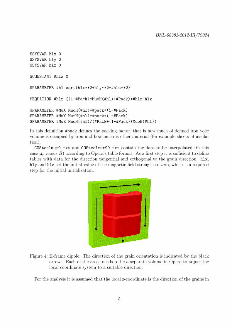
In this definition #pack defines the packing factor, that is how much of defined iron yokevolume is occupied by iron and how much is other material (for example sheets of insula-tion).GOSteelmur0.txt and GOSteelmur90.txt contain the data to be interpolated (in this
case µr versus B) according to Opera’s table format. As a first step it is sufficient to definetables with data for the direction tangential and orthogonal to the grain direction. hlx,hly and hlz set the initial value of the magnetic field strength to zero, which is a requiredstep for the initial initialization.
Figure 4: H-frame dipole. The direction of the grain orientation is indicated by the blackarrows. Each of the areas needs to be a separate volume in Opera to adjust thelocal coordinate system to a suitable direction.
For the analysis it is assumed that the local z-coordinate is the direction of the grains in
5

BNL-98381-2012-IR/79024
the soft-iron. The local coordinate system of various parts of the iron yoke (i.e. volumes)in Opera is adjusted so that the grain orientation aligns with the (local) z-direction.The magnetic permeability for the x, y and z direction in Cartesian coordinates is defined
by #MuX, #MuY and #MuZ.In the example under consideration parts of the iron yoke with different grain orientation
need to be different subdomains, as indicated in Fig. 4.For this analysis the material properties in grain direction (0◦) and perpendicular to that
are considered (90◦), which should be a worst case. To estimate the effect of the varyingµr with angle to the grain direction either a sensitivity study can be carried out (repeatingsimulations with a µr for a different angle) or a function of two variables (field and angle)can be used.Opera 2D was also employed, which in difference to Opera 3D solves for the magnetic
vector potential (Opera 3D solves for the scalar potential). In Opera 2D different BH-curves can be set for the x/y-direction.
4 Geometry
The simulations aimed to explain the behaviour of the fabricated test magnets at theUniversity of Mississippi, Oxford, MS, USA. A schematic of the first magnet is shown inFig. 5 (a); a second magnet using mitre-joints was simulated as well (see Fig. 5 (b)).
Figure 5: Geometries of the simulated magnets. Fig. (a) shows the first manufacturedmagnet using butt-joints, whereas Fig. (b) employs mitre-joints.
For the 3D simulations different slab thicknesses were simulated, from < 1 mm to 50 mm.
6

BNL-98381-2012-IR/79024
5 Simulation Results
It was found that a major challenge when modelling grain oriented steel is the convergenceof the simulations; this applies to all simulation packages under consideration. During theevaluation it was not possible to obtain simulation results accurate enough for the desiredpurpose.
Figure 6: COMSOL simulation result of the mitre geometry; the simulation result indicatesthat regions of high magnetization exist right next to regions of low magnetiza-tion, which is non-physical.
It was established that the convergence problems are directly linked to the anisotropicmaterial properties of the steel. In detail, the major complication seems to be the differentshape of the BH curves in different directions; the simulations converged when just scalingone of the existing BH curves (for example, for B perpendicular to the grain direction µr
is 5% of µr parallel to the grain direction).The following list gives a short overview of attempts to resolve this.
Software packages: A number of commercial and free software packages were tried, in-cluding Opera 2D/3D and COMSOL. Other software packages were considered (Pois-son Superfish2, FEMM3, MATLAB4), but dismissed due to lacking 3D capability. Theexperienced problems and performance was similar in comparison to Opera/COMSOLand the preliminary studies are omitted here.
Mesh size: Convergence could not be improved by decreasing the mesh size.
2http://laacg1.lanl.gov/laacg/services3http://www.femm.info4http://www.mathworks.com/
7

BNL-98381-2012-IR/79024
Figure 7: Opera 2D simulation result of the mitre geometry (Fig. (a), courtesy of Mauriciode Lima Lopes, FNAL) and Opera 3D simulation result of the butt-joint magnet(b). Both simulations did not converge.
Geometry: In addition to the butt-joint and mitre design additional, simplified geometrieswere tried. For example, the laminate thickness was increased to 50 mm to rule outany problems due to the thin lamination. Air gaps were introduced between jointsto improve convergence, without any success. Single laminates were modelled as wellas stacks of opposite ones.
BH curves: The smoothness of the BH curves was improved by adding more points or byusing more suitable interpolation functions. For Opera 3D, BH curves were includedin different ways (method described earlier and using the GUI, which allows to setdifferent BH curves for different directions in each volume) to rule out any interfaceproblems. In COMSOL the BH curve was included as a look-up table (linear/bilinearinterpolation) and an analytic expression.
Different BH-curves were tried to rule out any particular problem with grain orientedsteel. The models also did not converge when using two pre-supplied but differentBH-curves in Opera (e.g. ‘Default’ and ‘Armco Smith’). Fig. 8 (b) shows the resultof this attempt.
Re-implementation of the Magnetostatics Application Mode: To rule out any prob-lems with the pre-programmed application mode used in COMSOL for Magnetostatic
problems the PDE was re-implemented. The PDE (∇(
−1
µ0µr
∇Az
)
= Jext) was im-
plemented in the so-called coefficient and general form. Both re-implementationssuffered from the same convergence issues.
Solvers: In COMSOL a number of different solvers were tried. This included direct solvers
8
BNL-98381-2012-IR/79024
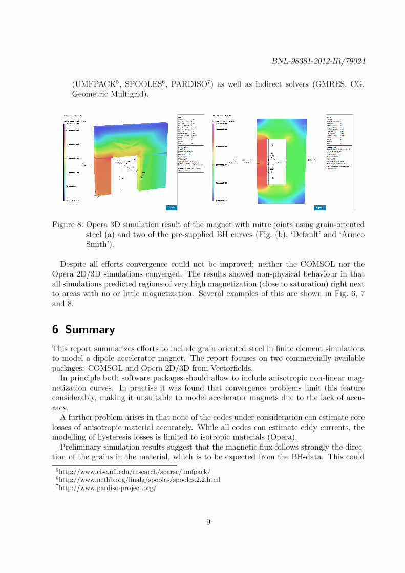
(UMFPACK5, SPOOLES6, PARDISO7) as well as indirect solvers (GMRES, CG,Geometric Multigrid).
Figure 8: Opera 3D simulation result of the magnet with mitre joints using grain-orientedsteel (a) and two of the pre-supplied BH curves (Fig. (b), ‘Default’ and ‘ArmcoSmith’).
Despite all efforts convergence could not be improved; neither the COMSOL nor theOpera 2D/3D simulations converged. The results showed non-physical behaviour in thatall simulations predicted regions of very high magnetization (close to saturation) right nextto areas with no or little magnetization. Several examples of this are shown in Fig. 6, 7and 8.
6 Summary
This report summarizes efforts to include grain oriented steel in finite element simulationsto model a dipole accelerator magnet. The report focuses on two commercially availablepackages: COMSOL and Opera 2D/3D from Vectorfields.In principle both software packages should allow to include anisotropic non-linear mag-
netization curves. In practise it was found that convergence problems limit this featureconsiderably, making it unsuitable to model accelerator magnets due to the lack of accu-racy.A further problem arises in that none of the codes under consideration can estimate core
losses of anisotropic material accurately. While all codes can estimate eddy currents, themodelling of hysteresis losses is limited to isotropic materials (Opera).Preliminary simulation results suggest that the magnetic flux follows strongly the direc-
tion of the grains in the material, which is to be expected from the BH-data. This could
5http://www.cise.ufl.edu/research/sparse/umfpack/6http://www.netlib.org/linalg/spooles/spooles.2.2.html7http://www.pardiso-project.org/
9

BNL-98381-2012-IR/79024
imply a relatively low tolerance against material faults and manufacturing tolerances, asfor magnetizations close to saturation the material behaves as a 1D-material. This mayjeopardize if not rule out the use of anisotropic materials for accelerator magnets. Furtherconcerns are long-term stability and resistance to radiation, which are not addressed inthis report.In summary, to study the potential benefits and shortcomings of Grain Oriented Steel
for accelerator magnets a significant effort has to be made to understand the nature ofthe convergence problems and the subsequent improvement of one of the available finiteelement codes.
10
BNL-98381-2012-IR/79024
References
[1] AK Steel. Oriented & TRAN-COR H ELECTRICAL STEELS. Product Data Bulletin,AK Steel, AK Steel Corporation, 9227 Centre Pointe Drive, West Chester, Ohio, 45069,USA, 2011.
[2] E. Moor. Private communication. Technical Support, Vector Fields Software, CobhamTechnical Services, 24 Bankside, Kidlington, Oxford OX5 1JE, UK, September 2011.
[3] D. Summers. Fast Ramping 750 GeV Muon Synchrotron. Presentation at Muon Accel-eration Program, Muon Collider 2011: Physics - Detectors - Accelerators, June 2011.Telluride, Colorado, USA.
[4] D. Summers, L. Cremaldi, R. Godang, B. Kipapa, H. Rice, et al. Muon accelerationto 750-GeV in the Tevatron tunnel for a 1.5- TeV mu+ mu- collider. Conf.Proc.,C070625:3178, 2007.
11