fea solution procedure - west virginia...
TRANSCRIPT
MAE 456 - Finite Element Analysis
FEA Solution Procedure
(demonstrated with a 1-D bar element problem)
Several slides from this set are adapted from B.S. Altan, Michigan Technological University

MAE 456 - Finite Element Analysis
FEA Procedure for Static Analysis1. Prepare the FE model
a. discretize (mesh) the structureb. prescribe loadsc. prescribe supports
2. Perform calculationsa. generate stiffness matrix (k) for each elementb. combine elements (assemble global stiffness matrix K)c. assemble loads (into global load vector R)d. impose support conditionse. solve equations (KD=R) for displacements
3. View resultsa. displacements b. reaction forces at restraintsc. element strainsd. element stressese. element forces
2

MAE 456 - Finite Element Analysis
The 1-D Bar ProblemGiven:
P
u1 u2 u3 u4 1
2 3 4
5
E1 = E5 = 200 GPa (1020 steel)
E2 = E3 = E4 = 70 GPa (1100 aluminum)
σy1 = σy5 = 295 MPa (1020 steel)
σy2 = σy3 = σy4 = 95 MPa (1100 aluminum)3

MAE 456 - Finite Element Analysis
The 1-D Bar Problem
Find: a) displacements (u1, u2, u3, u4),b) strains (ε1, ε2, ε3, ε4, ε5),c) stresses (σ1, σ2, σ3, σ4, σ5),d) internal forces (Fi,1, Fi,2, Fi,3, Fi,4, Fi,5),e) safety factor (SF).
4
A1 = A4 = A5 = 100 mm2
A3 = 200 mm2 A2 = 200 mm2
L1 = L5 = 3 m L2 = L3 = L4 = 1 mP = 50,000 N
Node number

MAE 456 - Finite Element Analysis
1. Prepare the FE Model• The structure is idealized in terms of nodes
and bar elements
P
1
2 3 4
5
P
u1 u2 u3 u4
21
3 45
5

MAE 456 - Finite Element Analysis
2.a. Generate Elemental Equations• If we fix the left end of a bar (with constant cross
section) it’s end displacement is given by:
• If the left end is NOT fixed, the relationshipbetween force and displacement is given by:
221
121
FuuL
AE
FuuL
AE
F2
u1 u2
F1
6
AEPL
P

MAE 456 - Finite Element Analysis
Generate Elemental Equations• These two equations can be conveniently expressed in
matrix form as:
• The different parts are known as:
– the elemental stiffness matrix
– the elemental displacement vector
– the elemental force vector
• This form allows us to easily combine the equations from all elements of a structure.
2
1
2
1
1111
FF
uu
LAE
1111
LAEk
2
1
uu
d
2
1
FF
f
7

MAE 456 - Finite Element Analysis
Generate Elemental Equations
1,4
1,1
4
1
1
11
1111
FF
uu
LEA
1,4
1,1
4
16
67.667.667.667.6
10FF
uu
3,3
3,2
3
2
3
33
1111
FF
uu
LEA
Element numberNode number
2,2
2,1
2
1
2
22
1111
FF
uu
LEA
2,2
2,1
2
16
21212121
10FF
uu
3,3
3,2
3
26
14141414
10FF
uu
8
MAE 456 - Finite Element Analysis
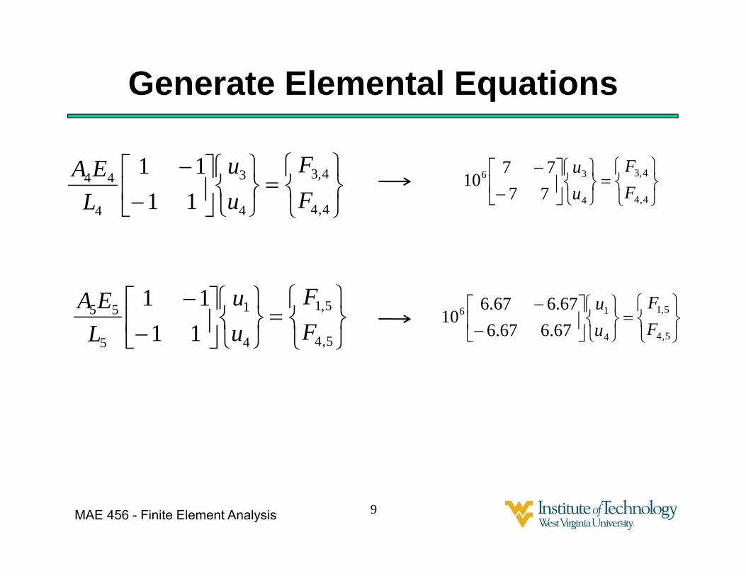
Generate Elemental Equations
5,4
5,1
4
1
5
55
1111
FF
uu
LEA
4,4
4,3
4
3
4
44
1111
FF
uu
LEA
5,4
5,1
4
16
67.667.667.667.6
10FF
uu
4,4
4,3
4
36
7777
10FF
uu
9

MAE 456 - Finite Element Analysis
2.b. Combine Elements
Node 1: 1,1F2,1F5,1F
R
05,12,11,1 RFFF
Elements are combined by considering the equilibrium of forces at each node
10
Node 2: 2,2F 3,2F
03,22,2 FF

MAE 456 - Finite Element Analysis
Combine ElementsNode 3: 3,3F 4,3F
04,33,3 FF
11
Node 4:1,4F4,4F5,4F
P
05,44,41,4 PFFF

MAE 456 - Finite Element Analysis
Combine Elements
P
R
FFFFFFF
FFF
00
5,44,41,4
4,33,3
3,22,2
5,12,11,1
The equations for each node can then be combined into one vector equation.
12
MAE 456 - Finite Element Analysis
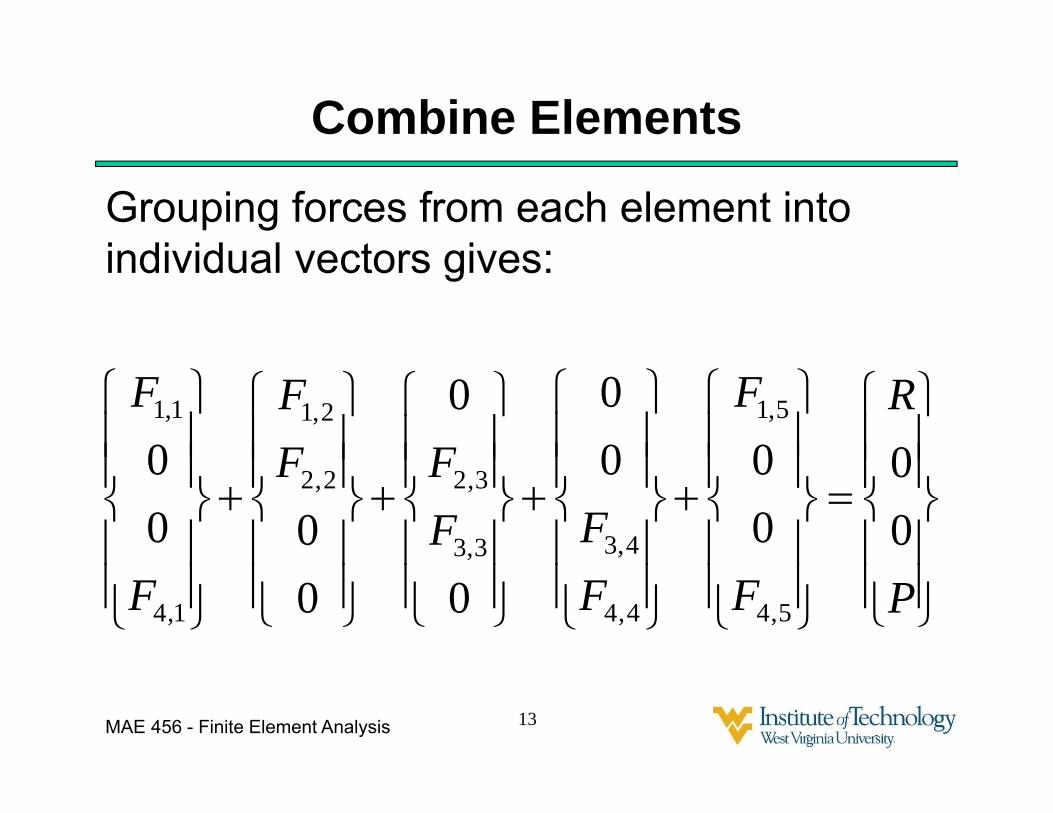
Combine Elements
P
R
F
F
FFF
FFF
F
F
00
000
0
0
0
000
0
5,4
5,1
4,4
4,33,3
3,22,2
2,1
1,4
1,1
Grouping forces from each element into individual vectors gives:
13

MAE 456 - Finite Element Analysis
Combine Elements
4
3
2
1
6
1,4
1,1
67.60067.60000000067.60067.6
1000
uuuu
F
FElement 1:
Element 2:
4
3
2
1
62,2
2,1
00000000002121002121
10
00
uuuu
FF
14

MAE 456 - Finite Element Analysis
Combine Elements
4
3
2
1
6
3,3
3,2
00000141400141400000
10
0
0
uuuu
FF
Element 3:
Element 4:
4
3
2
1
6
4,4
4,3
77007700
00000000
1000
uuuu
FF
15

MAE 456 - Finite Element Analysis
Combine Elements
4
3
2
1
6
5,4
5,1
67.60067.60000000067.60067.6
1000
uuuu
F
FElement 5:
16

MAE 456 - Finite Element Analysis
Combine Elements
P
R
uuuu
00
67.6767.67067.667.67714140
01414212167.667.602167.62167.6
10
1
4
3
2
1
6
17
P
R
uuuu
00
67.60067.60000000067.60067.6
77007700
00000000
00000141400141400000
00000000002121002121
67.60067.60000000067.60067.6
10
1
4
3
2
1
6

MAE 456 - Finite Element Analysis
Combine ElementsThe resulting overall matrix equation is:
P
R
uuuu
00
207013721140
01435211302134
10
1
4
3
2
1
6
18
“global stiffness matrix”
“global displacement vector”“global applied force vector”
KD=R

MAE 456 - Finite Element Analysis
2.c. Assemble LoadsInserting the load value(s):
6
1
4
3
2
1
6
1005.000
207013721140
01435211302134
10
R
uuuu
19

MAE 456 - Finite Element Analysis
2.d. Support Conditions• We have one support condition: u1= 0.• Support conditions can be solved two ways:
– Penalty method• Multiply equation ui = i by a large number and add to row i.• 1000x106 u1 = 0
P
u1 u2 u3 u4 1
2 3 4
5
Stiff spring
6
1
4
3
2
1
6
1005.000
207013721140
014352113021341000
10
R
uuuu
• This is equivalent to adding a stiff spring
20
MAE 456 - Finite Element Analysis
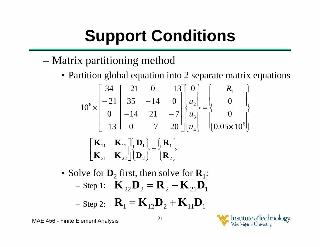
Support Conditions– Matrix partitioning method
• Partition global equation into 2 separate matrix equations
• Solve for D2 first, then solve for R1:– Step 1:
– Step 2:
6
1
4
3
26
1005.000
0
207013721140
01435211302134
10
R
uuu
2
1
2
1
2221
1211
RR
DD
KKKK
1112121
1212222
DKDKRDKRDK
21

MAE 456 - Finite Element Analysis
Support Conditions– Step 1: Solve for u2, u3, u4
05.000
207072114
01435
4
3
2
uuu
– Step 2: Solve for R1
4
3
26
1 1302110uuu
R
22

MAE 456 - Finite Element Analysis
2.e. Solving for Displacements• The global matrices (with applied boundary
conditions) are solved for displacements (D):D=K-1R
• In practice, the computer does not actually calculate K-1 , but solves for D directly, using techniques such as Gaussian Elimination.
23

MAE 456 - Finite Element Analysis
3.a. Solving for Strain• Once we know the displacements, we can
calculate the strain for each element.• In a one dimensional problem, the strain is
given by:
• For the constant cross-section bar, dxdu
Luu 12
24

MAE 456 - Finite Element Analysis
3.b. Stress and Internal Force• Below the yield stress, for uniaxial stress,
the stress is given by:
• The force in each bar can be calculated by:
or by:
E
AF
LuuAEF )( 12
25

MAE 456 - Finite Element Analysis
3.c. Safety Factor• For a statically loaded member, the Safety
Factor (SF) with respect to yielding failure can be computed as:
where sy is the material yield stress, andmax is the maximum stress.
• The SF for the entire structure is equal to the minimum of the SF of each member.
26

MAE 456 - Finite Element Analysis
Recommended Safety Factors• SF = 1.25 to 1.5 for exceptionally reliable materials used under
controllable conditions, subject to loads that can be determined with certainty – where low weight is important.
• SF = 1.5 to 2 for well-known materials, under reasonably constant environmental conditions, subject to loads that can be determined readily.
• SF = 2 to 2.5 for average materials operated in ordinary environments and subject to loads that can be determined.
• SF = 2.5 to 3 for less tried materials or for brittle materials under average conditions of environment and load.
• SF = 3 to 4 for untried materials used under average conditions of environment and load.
• SF = 3 to 4 also for better-known materials that are to be used in uncertain environments or subject to uncertain loads.
• Adjust SF for repeated loads, impact forces, and brittle materials.27
Adapted from Juvinall & Marshek, Fundamentals of Component Design, 4th Ed.

MAE 456 - Finite Element Analysis
What about Planar (2-D) Problems?• The equation for a bar element with an arbitrary
orientation in planar space is obtained by transforming the local element coordinate system to the global coordinate system.
28

MAE 456 - Finite Element Analysis
What about Planar (2-D) Problems?• Mathematically this is done by multiplying
the elemental stiffness equation by a rotation matrix:
29

MAE 456 - Finite Element Analysis
What about Spatial (3D) Problems?• Transformation matrices are again used to
transform the equations in the element coordinate system to the global coordinate system. (This time using the direction cosines.)
30