fea tutorials if1
TRANSCRIPT
MIDAS/FEA Training Series IF-1. Creating Interface Element
MIDAS Information Technology Co., Ltd.
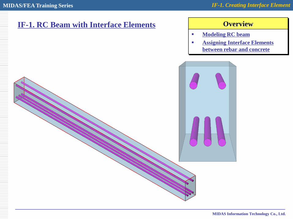
IF-1. RC Beam with Interface Elements Overview
Modeling RC beam
Assigning Interface Elements
between rebar and concrete

MIDAS/FEA Training Series IF-1. Creating Interface Element
MIDAS Information Technology Co., Ltd.
Step 1.
1
6
Analysis Control Dialog is automatically activated at startup.
3
2
4
5
1. Analysis > Analysis Control – “Control” tab
2. Analysis Type : 3D
3. Click Button
4. Unit : kN , mm
5. Click [OK] Button
6. Click [OK] Button
4

MIDAS/FEA Training Series IF-1. Creating Interface Element
MIDAS Information Technology Co., Ltd.
Step 2.
1. Geometry > Primitive Feature > Box…
2. Insert parameters as shown in Figure
3. Click [OK] Button
4. Geometry > Primitive Feature > Cylinder…
5. Insert parameters as shown in Figure
6. Click [OK] Button
2
3
5
6
MIDAS/FEA Training Series IF-1. Creating Interface Element
MIDAS Information Technology Co., Ltd.
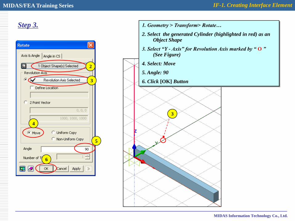
Step 3. 1. Geometry > Transform> Rotate…
2. Select the generated Cylinder (highlighted in red) as an Object Shape
3. Select “Y - Axis” for Revolution Axis marked by “ O ” (See Figure)
4. Select: Move
5. Angle: 90
6. Click [OK] Button
2
3
3
4
5
6
MIDAS/FEA Training Series IF-1. Creating Interface Element
MIDAS Information Technology Co., Ltd.
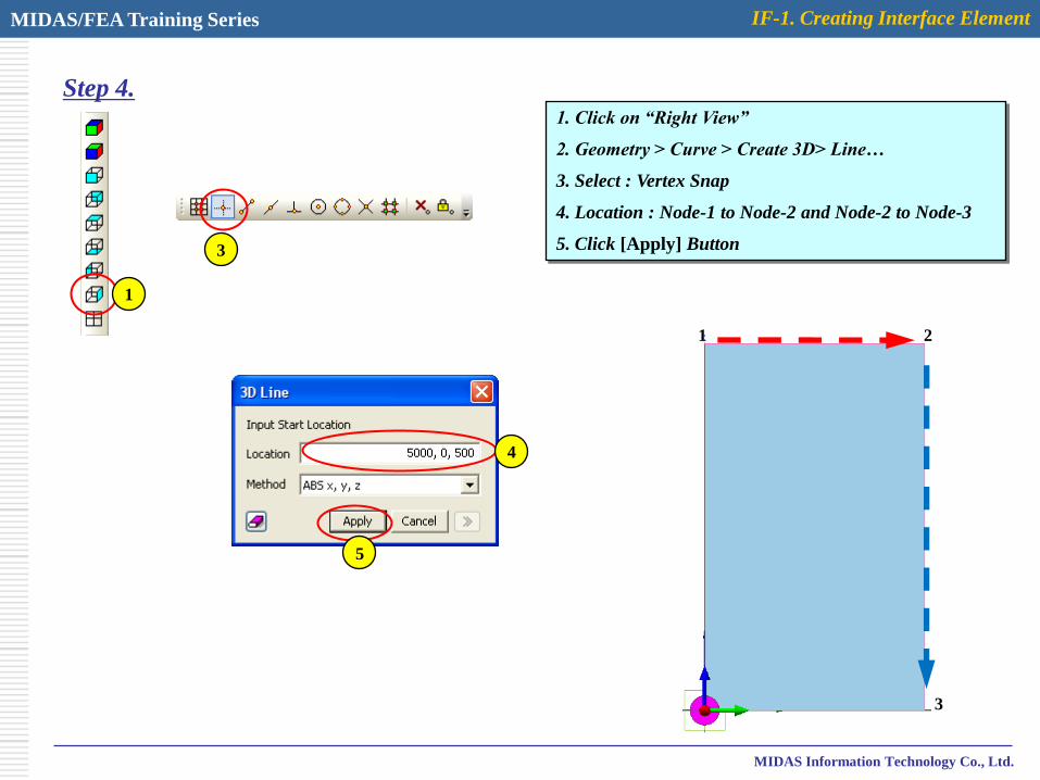
Step 4.1. Click on “Right View”
2. Geometry > Curve > Create 3D> Line…
3. Select : Vertex Snap
4. Location : Node-1 to Node-2 and Node-2 to Node-3
5. Click [Apply] Button
1
3
1 2
3
4
5

MIDAS/FEA Training Series IF-1. Creating Interface Element
MIDAS Information Technology Co., Ltd.
Step 5. 1. Geometry > Transform> Translate…
2. Select Top edge as shown in Figure
3. Select “Z - Axis” for Direction marked by “ O ” (See Figure)
4. Select: Non-Uniform Copy
5. Distance: “-100, -300”
6. Click [Apply] Button2
3
3
4
5
6
2
MIDAS/FEA Training Series IF-1. Creating Interface Element
MIDAS Information Technology Co., Ltd.
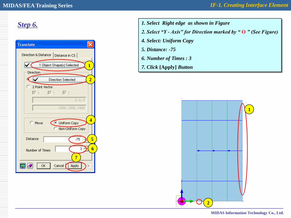
Step 6. 1. Select Right edge as shown in Figure
2. Select “Y - Axis” for Direction marked by “ O ” (See Figure)
4. Select: Uniform Copy
5. Distance: -75
6. Number of Times : 3
7. Click [Apply] Button1
2
2
4
5
7
1
6
MIDAS/FEA Training Series IF-1. Creating Interface Element
MIDAS Information Technology Co., Ltd.
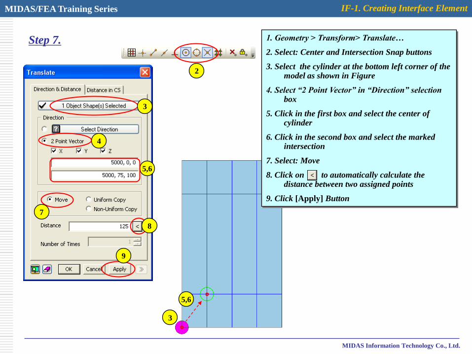
Step 7. 1. Geometry > Transform> Translate…
2. Select: Center and Intersection Snap buttons
3. Select the cylinder at the bottom left corner of the model as shown in Figure
4. Select “2 Point Vector” in “Direction” selection box
5. Click in the first box and select the center of cylinder
6. Click in the second box and select the marked intersection
7. Select: Move
8. Click on to automatically calculate the distance between two assigned points
9. Click [Apply] Button
3
3
4
7
8
9
2
5,6
5,6

MIDAS/FEA Training Series IF-1. Creating Interface Element
MIDAS Information Technology Co., Ltd.
Step 8. 1. Select the cylinder as shown in Figure
2. Select “2 Point Vector” in “Direction” selection box
3. Click in the first box and select the center of cylinder
4. Click in the second box and select the marked intersection
5. Select: Uniform Copy
6. Click on to automatically calculate the distance between two assigned points
7. Number of Times: 2
8. Click [Apply] Button
1
1
2
5
6
8
3,4
3,4
7

MIDAS/FEA Training Series IF-1. Creating Interface Element
MIDAS Information Technology Co., Ltd.
Step 9. 1. Select the highlighted cylinders as shown in Figure
2. Select “2 Point Vector” in “Direction” selection box
3. Click in the first box and select the center of cylinder
4. Click in the second box and select the marked intersection
5. Select: Uniform Copy
6. Click on to automatically calculate the distance between two assigned points
7. Number of Times: 2
8. Click [Apply] Button
1
1
2
5
6
8
3,4
3,47
MIDAS/FEA Training Series IF-1. Creating Interface Element
MIDAS Information Technology Co., Ltd.
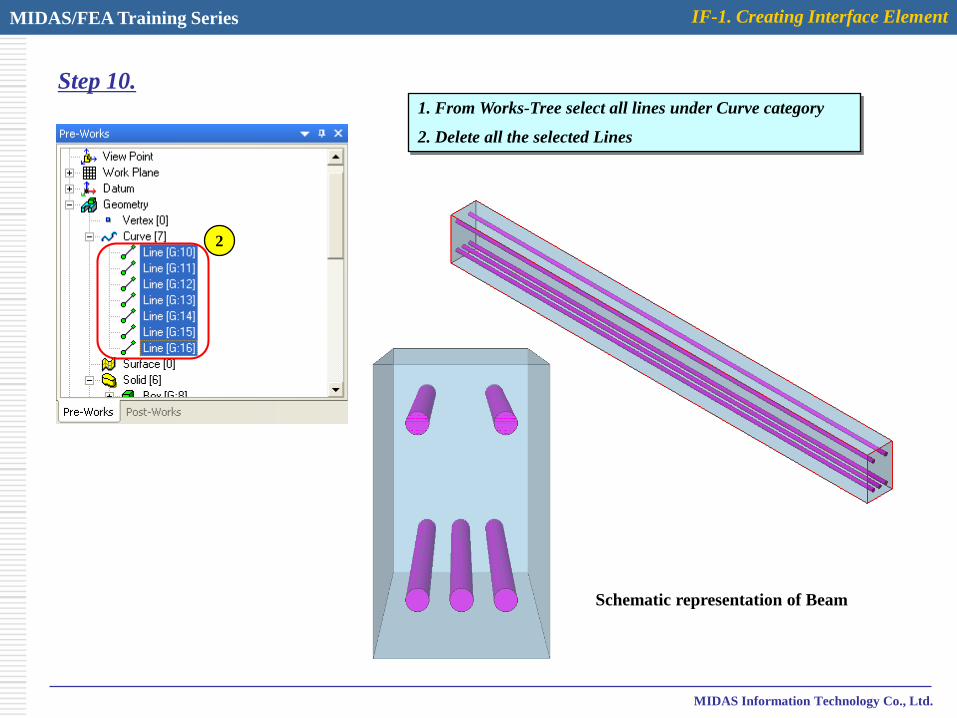
Step 10.1. From Works-Tree select all lines under Curve category
2. Delete all the selected Lines
Schematic representation of Beam
2

MIDAS/FEA Training Series IF-1. Creating Interface Element
MIDAS Information Technology Co., Ltd.
Step 11.1. Geometry > Boolean Operation > Cut…
2. Select the main body as shown in Figure
3. Select 5 cylinders for Boolean Tools
4. Unselect: Delete Tool Object(s)
5. Click [OK] Button2,3
5
4
2
MIDAS/FEA Training Series IF-1. Creating Interface Element
MIDAS Information Technology Co., Ltd.
Step 12.
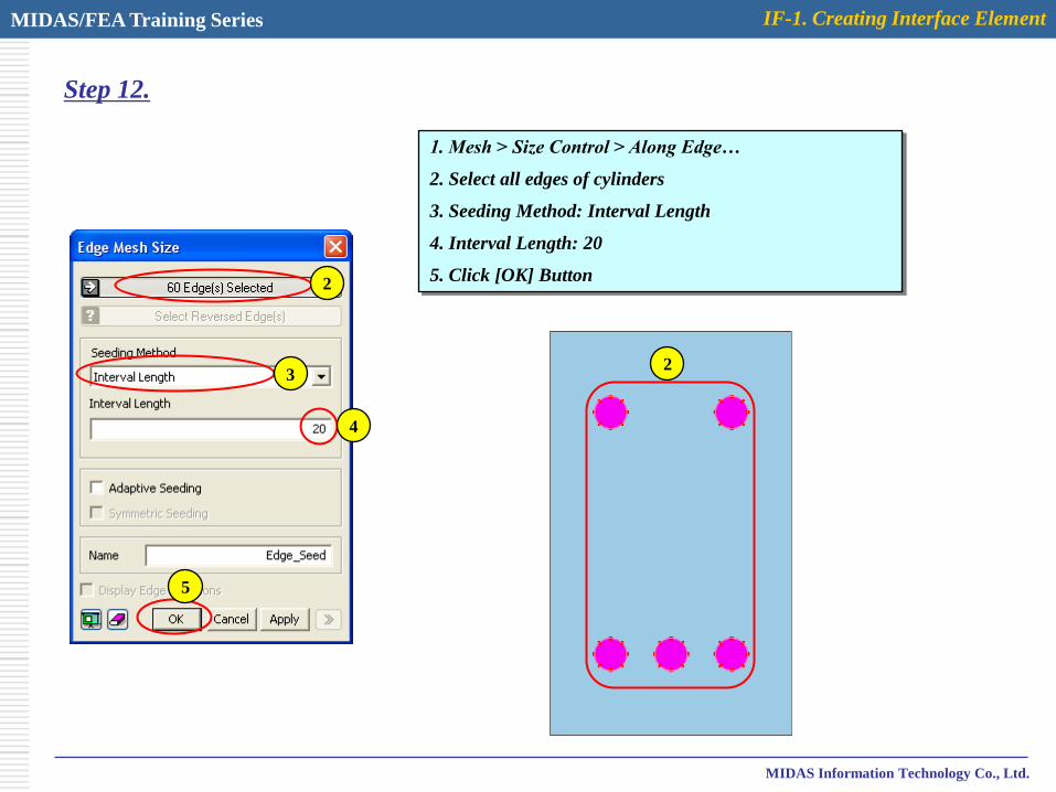
1. Mesh > Size Control > Along Edge…
2. Select all edges of cylinders
3. Seeding Method: Interval Length
4. Interval Length: 20
5. Click [OK] Button
2
2
3
4
5

MIDAS/FEA Training Series IF-1. Creating Interface Element
MIDAS Information Technology Co., Ltd.
Step 13.1. Mesh > Auto Mesh > Solid…
2. Select: All
3. Mesh Size: Element Size (80)
4. Property : 1
5. Select: Register Each Solid Independently
6. Click [OK] Button
Model with assigned seeds Generated mesh
2
6
3
4
5

MIDAS/FEA Training Series IF-1. Creating Interface Element
MIDAS Information Technology Co., Ltd.
Step 14.
1. From Works-Tree right click on “Geometry” and select “Hide All”
2. Analysis > Property… > Create > Interface…
3. Name: Interface
4. Click on to define associated material model
5. Click on “Create” and select Interface Tab
6. Name: Interface Mat.
7. Interface Nonlinearities: Bond Slip
8. Insert corresponding parameters as shown in Figure*
9. Click [OK] and [Cancel] Buttons
1
2
3
4
5
6
8
7
* The assigned parameters are just for example and there is no specific reference for them.
9
9
9
MIDAS/FEA Training Series IF-1. Creating Interface Element
MIDAS Information Technology Co., Ltd.
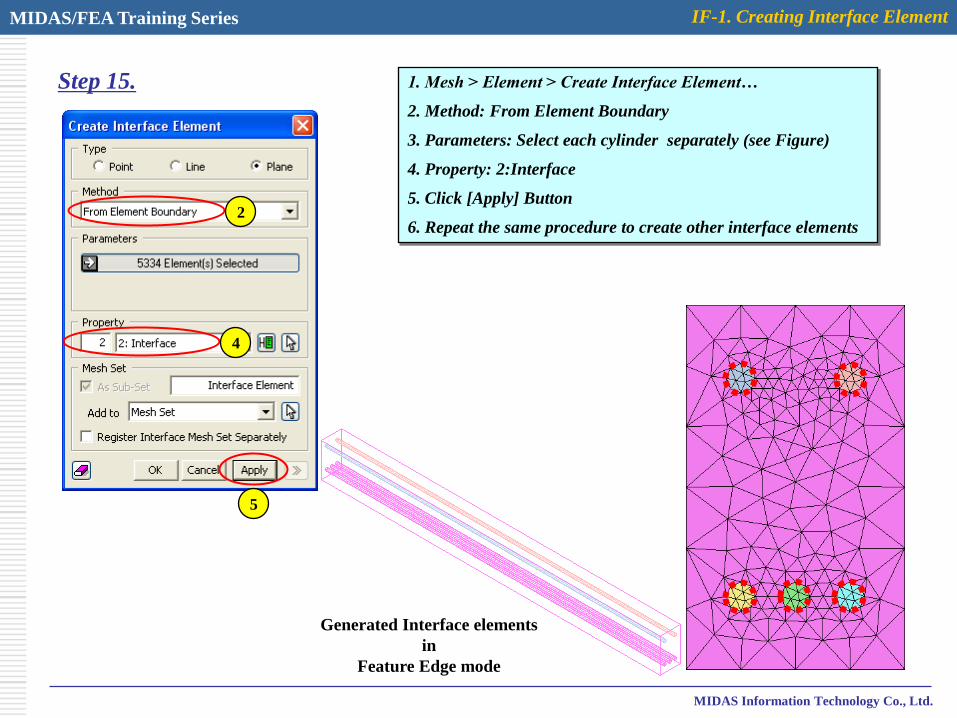
Step 15. 1. Mesh > Element > Create Interface Element…
2. Method: From Element Boundary
3. Parameters: Select each cylinder separately (see Figure)
4. Property: 2:Interface
5. Click [Apply] Button
6. Repeat the same procedure to create other interface elements2
4
5
Generated Interface elements
in
Feature Edge mode