feasibility and economic aspects of vactrains · pdf filefeasibility and economic aspects of...
TRANSCRIPT

Feasibility and Economic Aspects of Vactrains
An Interactive Qualifying Project
Submitted to the faculty
Of the
Worcester Polytechnic Institute
Worcester, Massachusetts, USA
In partial fulfilment of the requirements for the
Degree of Bachelor of Science
On this day of
October11, 2007
By
Alihusain Yusuf Sirohiwala
Electrical and Computer Engineering ‘09
Ananya Tandon Biomedical Engineering ‘08
Raj Vysetty Electrical and Computer Engineering ‘08
Project Advisor: Professor Oleg Pavlov, SSPS

2
Abstract Vacuum Train refers to a proposed means of high speed long-haul transportation
involving the use of Magnetic Levitation Trains in an evacuated tunnel. Our project was
aimed at investigating the idea in more detail and quantifying some of the challenges
involved. Although, several studies on similar ideas exist, a consolidated report
documenting all past research and approaches involved is missing. Our report was an
attempt to fill some of the gaps in these key research areas.
3
Acknowledgements There are many people without whose contribution this project would have been
impossible. Firstly we would like to thank Professor Pavlov for his constant guidance and
support in steering this IQP in the right direction. Next, we would like to thank Mr. Frank
Davidson and Ms. Kathleen Lusk Brooke for expressing interest in our project and
offering their suggestions and expertise in the field of macro-engineering towards our
project.

4
Table of Contents 1 Introduction .............................................................................................................. 10
2 History of Vactrains ................................................................................................. 12
3 Technology ............................................................................................................... 15
3.1 High Speed Rail .......................................................................................................... 15 3.1.1 Tilting Trains ......................................................................................................................... 16
3.2 Maglev (Magnetic Levitation) Trains ....................................................................... 17 3.2.1 Working principle of the Maglev .......................................................................................... 18 3.2.2 Levitation .............................................................................................................................. 19 3.2.3 Propulsion .............................................................................................................................. 20 3.2.4 Guidance ................................................................................................................................ 21 3.2.5 Advantages of the Maglev ..................................................................................................... 22
3.3 Tunneling Technologies and their Applicability to the Vactrains Project ............ 24 3.3.1 Tunneling with Tunnel Boring Machines .............................................................................. 25 3.3.2 The Tube Tunnel ................................................................................................................... 27 3.3.3 Artificial Vacuums Case Study: LIGO – The World’s Largest Artificial Vacuum. .............. 30
3.4 Aerodynamic drag ...................................................................................................... 34 3.4.1 Aerodynamics of the High speed railway system .................................................................. 34 3.4.2 Aerodynamics of the Maglev system .................................................................................... 37 3.4.3 Consumption of Power due to Aerodynamic Drag ................................................................ 38
4 Effects of High Speed Travel on the Human Body ................................................ 40
4.1 What is a G-Force? ..................................................................................................... 41
4.2 Directional G-Forces .................................................................................................. 44
4.3 G-Force Calculation: Trans-Atlantic Route ............................................................ 47
5 Vactrain Costs .......................................................................................................... 50
5.1 Vacuum costs .............................................................................................................. 51
5.2 Material Costs ............................................................................................................. 54
6 Pricing of the Vactrain ............................................................................................ 55
6.1 Concorde ..................................................................................................................... 56
6.2 Comparing Vactrain with the Concorde .................................................................. 58
7 Safety of a Vactrain.................................................................................................. 59
8 The Swissmetro ........................................................................................................ 63
8.1 Need for the project .................................................................................................... 63
8.2 Historical Timeline ..................................................................................................... 65
8.3 Implications of the successful implementation of Swissmetro ................................ 66
9 Effects of a New Mode of Transport ....................................................................... 67
10 Conclusion ................................................................................................................ 68
11 Bibliography ............................................................................................................. 71

5
Table of Figures
Figure 1: Swedish X2000 tilting train, top speed 200km/h or 125mph [2] ...................... 16
Figure 2 Maglev at the Shanghai airport [3] ..................................................................... 18
Figure 3: Functions of the maglev [4]............................................................................... 19
Figure 4: EMS and EDS [4] .............................................................................................. 20
Figure 5 Propulsion and Guidance .................................................................................... 21
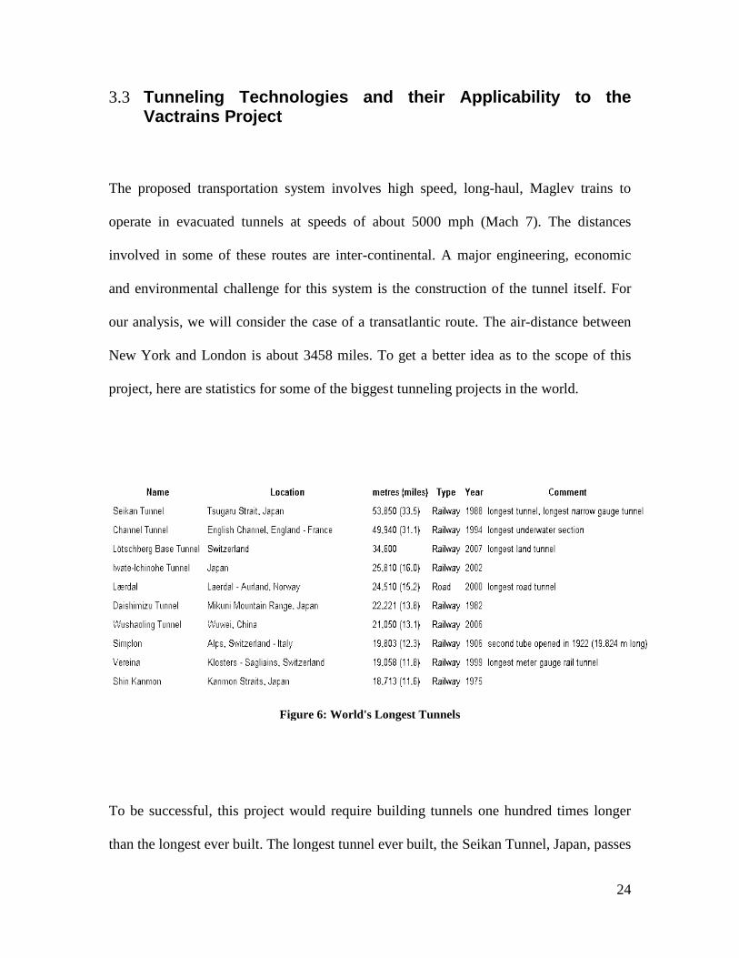
Figure 6: World's Longest Tunnels ................................................................................... 24
Figure 7 One of the world's largest TBMs with a diameter of 14m. ................................ 26
Figure 8: Major Tectonic Plates in the Americas ............................................................. 27
Figure 9: Proposed Tube Tunnel Section.......................................................................... 27
Figure 10: Left: Anchored Tethers, Right: Foam Coated Gasket for Lining Tube .......... 28 Figure 11: Immersion Pontoon Lowering Tube Section................................................... 28
Figure 12: LIGO Hanford, Washington. Each tube is about 2km long. ........................... 31
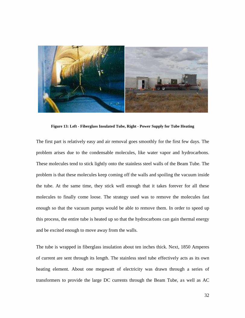
Figure 13: Left - Fiberglass Insulated Tube, Right - Power Supply for Tube Heating .... 32 Figure 14: Copper Cables for Heating Tube ..................................................................... 33
Figure 15: Pressure waves in a tunnel [19] ....................................................................... 36
Figure 16 : Development of micro-pressure waves[18] ................................................... 37
Figure 17: Time vs Acceleration ...................................................................................... 42
Figure 18: Colonel Stapp’s experiment on acceleration effects ....................................... 43
Figure 19: G-Forces .......................................................................................................... 45
Figure 20: Proposed velocity curve .................................................................................. 48
Figure 21: The Channel Tunnel Model ............................................................................. 50
Figure 22 SK Water Ring Vacuum Pump......................................................................... 51
Figure 23: Specification for SK Pump [31] ...................................................................... 52
Figure 24 An HRC Steel Coil ........................................................................................... 54
Figure 25 : Concorde flight operated by Air France ......................................................... 56
Figure 26 : Inside the Concorde ........................................................................................ 57
Figure 27 : Death rate in Aircrafts .................................................................................... 60
Figure 28 : Fatalities in Automobiles................................................................................ 61
Figure 29 : Fatalities in Railways ..................................................................................... 61
Figure 30: The Swissmetro ............................................................................................... 63
Figure 31: Possible Routing Map ..................................................................................... 64
Figure 32: A model of the underground vacuum train ..................................................... 66
Figure 33 : Ships vs. Aircrafts .......................................................................................... 67
6
Executive Summary
Imagine being able to live in New York and work in London. Imagine having the ability
to travel between continents by the time you finish watching an episode of your favorite
television series. In today’s global village where distances have been shortened by
advanced communication mediums, high speed travel, as proposed by the Vactrain, is the
obvious next step.
Vactrain (Vacuum Train) refers to a proposed means of long-haul transportation
involving the use of Magnetic Levitation Trains in an evacuated tunnel. The idea is to
travel very large distances in a very short time. We believe that having such a
transportation system would be beneficial both economically and socially. The Vactrain
is based on the concept of eliminating frictional losses and aerodynamic drag to attain top
speeds of about 5000mph. At these speeds, a New York to London trip could be
completed in under an hour.
Our project was aimed at investigating the idea in more detail and quantifying some of
the challenges involved. In addition to determining the challenges, we also tried to study
the practical and economic side of the problem. We researched the technology involved
in each of the major sub-systems of the Vactrain and simultaneously considered
economic aspects such as initial costs, pricing and feasibility. In a lot of the research, we
drew parallels with existing macro-engineering projects that were relevant either in their
scale or in the kind of technology used. These factors made this project a perfect fit as an
Interactive Qualifying Project at WPI. The technologically advanced nature of the project

7
and the associated social and economic aspects go very well with the mission of our
University. This project aims at bringing together a multitude of skills towards studying
an idea.
WPI is no stranger to the concept of Vactrains. Robert Goddard - father of modern rocket
science and WPI alumnus, was also one of the initial pioneers of the Vactrain. Although
his designs were found only after his death in 1945, his work is still the basis of the
modern Vactrain model.
Macro Engineering implies the interdisciplinary formulation, design, and implementation
of large scale projects that can contribute to human progress. The major projects that we
used as case studies were: LIGO-Laser Interferometer Gravitational Wave Observatory,
Swissmetro – a high-speed underground maglev being worked on in Switzerland,
Concorde – the supersonic passenger jet, and lastly, the Channel Tunnel – the
revolutionary tunnel joining France and England. We worked closely with Frank
Davidson and Kathleen Lusk Brooke. Professor Frank Davidson was a co-Founder of the
famous Channel Tunnel Study Group in the 1950s that led to the construction of the
Channel Tunnel. He was also an MIT professor and Director of the Macro-Engineering
group at MIT. Dr. Kathleen Lusk Brooke is the Founder and Managing Director of the
Center for the Study of Success and a former Harvard and MIT professor. Professors
Davidson and Brooke founded the field of Macro-Engineering while at MIT. Mr.
Davidson sponsored our IQP study.

8
For a lot of our analysis, we assumed the transatlantic route for the Vactrain. This route
has also been studied by other researchers in the past and coined as “The Trans-Atlantic
Tunnel”. To predict the overall costs, we estimated the cost of the raw materials and
anticipated energy bills for maintaining vacuum levels. The effects of high speed travel
on the human body were assessed and parameters such as force and acceleration were
roughly quantified. A comparison was made between Concorde and the Vactrain as they
are very similar with respect to the potential clientele. Analyzing the reasons for
Concorde’s downfall gave us an insight into the pitfalls that needed to be considered.
Another outcome of this comparison was estimating the fare of a Vactrain so that
equilibrium exists between recovering manufacturing costs and being affordable at the
same time. The next big step was to determine safety levels for the Vactrain.
The problem of determining how safe the Vactrain should be was tackled by using
airplanes as a yardstick. The death rate in aircraft over the proposed transatlantic route
was used to develop a safety standard for the Vactrain. A case study was performed on
the Swissmetro, which is an inter-country partial vacuum maglev train, and hence similar
in principle to the working of the Vactrain. The work being done on the Swissmetro
suggests that the concept of Vactrain is not a far-fetched vision but a plausible next step.
In summary, the Vactrain is an exciting project that will have enormous effects on the
economy of many countries and will change people’s notion of travel forever. At the very
outset, the Vactrain might seem an implausible project, but in principle it is quite simple
considering that the most of the involved sub-systems are already realized in various
other Macro-Engineering projects. This project covered a variety of topics dealing with

9
the concepts behind the technology of the Vactrain. We also analyzed the economic as
well as the safety issues.

10
1 Introduction
Have you ever been on an 8 hour flight from NY to London, and dreamt how much easier
life would have been if the travel time was only an hour? Did you ever dream of the west
and the east coast being just 15 minutes away? The Vacuum train is a fascinating
proposal that would make these dreams a distinct possibility by its ability to attain speeds
around 5000 km/hr. In the larger context, the Vacuum train might be the next biggest step
in the transportation industry after the invention of the aircraft. The Vactrain caters
specifically to a set of clients for whom time is of paramount importance. A
transportation system of this kind might have multiple advantages on economy and
society.
The Vacuum train uses the current maglev technology and takes it to the next level by
implementing it in an evacuated tunnel. The costs for such a project are enormous and
hence the economics behind the project are extremely critical. In this report, our main
focus besides explaining the technology behind the maglev was to look at the economic
feasibility and safety aspects. We looked at economic issues such as the total construction
costs and potential fare pricing of the Vactrain. We also considered safety issues such as
the effects of high speed travel on the human body.
We researched and analyzed a lot of articles, data and performed case studies to draw
conclusions on the feasibility of the Vactrain. In the initial part of the report, we
explained the working of each of the subsystems; the Maglev and the evacuated tunnels,
in great detail and looked at the different variations of the technologies. We assessed the

11
effects that high-speed travel might have on the human body. Also, we estimated the
tunneling costs by performing an in-depth analysis using the costs of the raw materials.
Furthermore, we came up with fare prices that might be successful in recovering the
initial costs without risking over-pricing. We performed case studies on LIGO, Concorde
and the Swissmetro as they were highly relevant to our analysis of the Vactrain.
The Vactrain project has not come a long way from the proposal stage. There was a lot of
research done on the technical aspects of the various subsystems within a Vactrain
earlier. However, there seemed to be gap in the research done so far on the economic and
safety issues. Our report was an attempt to fill some of the gaps in these key research
areas. In the first chapter, we start by discussing in great detail the technology of the
Vactrain. In the following chapter, we outline the effects of high speed on the human
body. The subsequent sections represent our analysis on the economic issues, namely the
chapters on Vactrain costs and Vactrain pricing. The discussion in the final chapters was
on the plausible effects of the Vactrain on the transportation and a study on the
Swissmetro, an interesting proposal of a maglev train in partial vacuum.

12
2 History of Vactrains
The concept of Vactrains is not a recent one. Proposals have been made for a non-
evacuated transatlantic tunnel which would link the United States and Great Britain. This
idea was also highlighted in the German film, Der Tunnel which came out in 1933 and its
English version, the British film, Transatlantic Tunnel, which came out in 1935. The
modern concept of the Vactrain, as it is understood today, consisting of evacuated tubes
and involving maglev technology was first proposed by American engineer Robert
Goddard (Wikipedia).
Robert Goddard was an undergraduate at Worcester Polytechnic Institute. During his
time in WPI, he wrote a paper in which he proposed a method for balancing aeroplanes,
which got published in the Scientific American. After getting his B.S. in WPI, Goddard
enrolled in Clark University where he did his Masters and then continued his research at
Princeton. Robert Goddard launched the world’s first liquid fuelled rocket in 1926. He
launched rockets which could attain speed of up to 550 miles an hour. Even though his
work was revolutionary, he got little credit for his work. Along the years, he eventually
came to be called one of the Fathers of modern rocketry. His documents on Vactrains too
were discovered after his death (Mag). As a university student he designed detailed
prototypes of the Vactrain. According to the train designs which were found after his
death in 1945, his train would travel from Boston to New York in 12 minutes at a speed
of 1000 mph.

13
The first time that Vactrains made headlines was in the 1970s when Robert F. Salter, who
was a leading advocated of the RAND corporation (Research and Development),
published engineering articles in 1972 and in 1978 (Wikipedia). As said by Robert Salter,
in an interview by LA times, the U.S. government could build a tube shuttle system with
the technologies available at that time fairly easily. He also said that such systems reduce
damage done to the environment by aviation and surface transportation. Although he said
that underground Very High Speed Transportation (tube shuttles) was the nation’s next
logical step, his plan never became a reality.
During the time these reports were being published, national prestige was of
consideration as Japan’s bullet train was in operation and research in Maglev trains was
on. Maglev or Magnetic Levitation Transport is a form of transportation that suspended,
guided and propelled vehicles using electromagnetic forces. Trans-planetary subway
service would be established by the American Planetran in the United States which could
commute to Los Angeles from New York City in one hour. This tunnel was to be buried
several hundred feet deep in solid rock formations. Alignment was to be taken care of by
using lasers and tungsten probes would be used to melt through igneous rock formations.
Partial vacuum was to be maintained so that drag could be minimized. Passengers would
experience forces up to 1.4 times that of gravity and the speed of the trip would be 3000
mph. This would require using gimbaled compartments. A gumball is a mechanical
device which allows the rotation of an object in multiple directions. It is made up of two
or three pairs of pivots mounted on axes at right angles. Construction costs estimated

14
were magnanimous, (around US$ 1 trillion) which was why Salter’s proposal was not
executed.
There have been recent proposals on Vactrains by Frank Davidson, a pioneer of the
Channel Tunnel project and Yoshihiro Kyonati, a Japanese Engineer, who tackled
transoceanic problems by floating a tube above the ocean floor, anchored with cables.
This tube was proposed to be at a depth of 100 feet from the ocean surface to avoid water
turbulence (Mag).

15
3 Technology
3.1 High Speed Rail
High speed is a relative term and the definition of high speed rail varies from country to
country. The International Union of Railways (UIC) classifies high speed rail as all trains
that can travel above 250km/hr. At present, there are a number of countries that have
access to high speed rail with the major ones being Japan, France, United Kingdom, Italy,
Germany and Spain. (International Union of Railways)
As the automobile industry rose during the mid twentieth century and the cars were fast
enough to travel at speeds of regular trains, passengers were more inclined to use cars
instead of railroad. High Speed Rail was seen as an attempt to regain railway passengers
who seemed to be moving towards other modes of transport. The first successful “High
speed train” that was launched was Japan’s Shinkasen which was launched during 1964
and it was able to achieve speeds up to 200km/hr. (Wikipedia)
To have a high speed rail system, making the high speed train is only one of the tasks
involved. The track on which the train runs is critical in a successful high speed rail
system. As is the case with roads, railway tracks have speed restrictions and very often
the speed restrictions are way below the top speed of the train. It is not all that difficult to
build a train that can travel at fast speeds; however building high speed rail tracks that are
good enough to allow the trains to travel smoothly and safely at 250-300hm/hr is
considered a bigger challenge. (Keating)

16
A dedicated high speed rail track has many features that allow the train to travel at its full
speed for the maximum time. Curves on the high speed rail are built with very high radii,
which enable the train to travel without having to slow down much at the curves. It is also
made sure that there is a lot of spacing between the tracks to make sure that the pressure
created when two trains cross each with such high speeds in opposite directions is not too
much. There are no level crossings, and also all the tracks are fenced off completely.
These steps are taken to increase the safety levels. (Mag)
When faced with the challenge of building a high speed railway transport system,
operating companies have to choose between tilting trains and building a new dedicated
high speed railway line. Tilting trains are often considered a feasible option when
building a new railway line is beyond the budget of the project.
3.1.1 Tilting Trains
Figure 1: Swedish X2000 tilting train, top speed 200km/h or 125mph [2]

17
Tilting trains are a major form of High speed trains. These trains are based on tilting
technology at the corners. Regular trains are forced to slow down while nearing corners
and then speed up again. Due to the deceleration time required even for gentle corners,
trains will not be able to travel at their highest possible speed for long which has a huge
bearing on the overall average speed. When sitting on a corner going at speed there are
two forces acting on you, gravitational force and the centrifugal force which is
accelerating you into the corner. The resultant of the two forces pushes you to the side
and into the seat. However if the train is tilting, then the normal contact force of you on
your seat will be the same as the resultant force you are experiencing. This means as far
as the passenger is concerned he or she is just being pulled into his or her seat, and he or
she is used to that so no discomfort is felt. (Keating)
3.2 Maglev (Magnetic Levitation) Trains
Magnetic Levitation trains, more commonly called the maglev, are a highly innovative
form of high speed transportation. Maglev trains are completely different from the
regular train in their functioning. As the name suggests, the train is levitated above the
track with the help of magnets and runs on the principle of electromagnetism. There
exists no friction between the track and the train, which allows the maglev trains to travel
way faster than conventional train. Maglev trains are able to travel at speeds around
500km/hr. The first maglev train stated during the year 2004 in Shanghai, which
transports passengers from downtown to the Shanghai Airport. The train is able to travel
the distance of 30km in 7 minutes. (Wikipedia)

18
Figure 2 Maglev at the Shanghai airport [3]
3.2.1 Working principle of the Maglev
The two major types of maglev technologies are based on Electromagnetic suspension
(EMS) and Electrodynamic suspension (EDS). The EMS technology, an attraction based
technology, is the more popular and commercially tested of the two technologies. The
EDS technology is based on repulsion and has been developed recently in Japan and is
still in the prototype phases.
There are three main functions that each of the maglev technologies performs, which is
shown in Figure 3. (Wikipedia)
• Levitation
• Propulsion
• Guidance

3.2.2 Levitation
The first task of a maglev system is to get off the track and stay suspended which is
achieved through levitation. The two primary maglev technologies, EMS and EDS, are
distinguished primarily based on their methods of levitation. The EMS technology uses
magnetic attraction to levitate the train. As shown in
on the small J-shaped portion of the maglev train below the g
electromagnets are attracted to the magnets which are under the guide way which lifts the
train upward. There will be a constant gap between the track and the train maintained by
feed back circuits and a system of sensors. The EMS system is
fundamentally unstable as the magnetic forces increase exponentially as the two magnets
get closer to each other (Jacobs)
Figure 3: Functions of the maglev [4]
The first task of a maglev system is to get off the track and stay suspended which is
achieved through levitation. The two primary maglev technologies, EMS and EDS, are
distinguished primarily based on their methods of levitation. The EMS technology uses
agnetic attraction to levitate the train. As shown in Figure 4, there are electromagnets
shaped portion of the maglev train below the guide way. These
electromagnets are attracted to the magnets which are under the guide way which lifts the
train upward. There will be a constant gap between the track and the train maintained by
feed back circuits and a system of sensors. The EMS system is considered to be
fundamentally unstable as the magnetic forces increase exponentially as the two magnets
: Functions of the maglev [4]
19
The first task of a maglev system is to get off the track and stay suspended which is
achieved through levitation. The two primary maglev technologies, EMS and EDS, are
distinguished primarily based on their methods of levitation. The EMS technology uses
, there are electromagnets
uide way. These
electromagnets are attracted to the magnets which are under the guide way which lifts the
train upward. There will be a constant gap between the track and the train maintained by
considered to be
fundamentally unstable as the magnetic forces increase exponentially as the two magnets

Figure
The EDS technology, as mentioned earlier, is based on repulsive forces. Most maglev
trains based on EDS have Superconducting magnets (SCMs) under the train. These
magnets induce current in the guide way which levitates the train in a stable manner
using repulsive forces. These repulsive forces increase as distance increase as the
distance between the guide way and the train decreases. However, the train needs to reach
at least 25 km/hr before it can levitate off the ground which can be attained by using
wheels. The EDS system is theoretically supposed to go faster than the EMS as the air
gap between the train and the guide w
3.2.3 Propulsion
Maglev trains are distinguished primarily based on th
they need a propulsion system that would accelerate the train. In the EMS system, based
on electromagnetic attraction, the train also propels forward using the same principle.
However, the magnets used for levitation and
different. When the magnets that are placed on the guideway are activated, they are
attracted to the magnets that are under the maglev. The activated electromagnets of the
guideway are just in front of the maglev
Figure 4: EMS and EDS [4]
The EDS technology, as mentioned earlier, is based on repulsive forces. Most maglev
trains based on EDS have Superconducting magnets (SCMs) under the train. These
magnets induce current in the guide way which levitates the train in a stable manner
pulsive forces. These repulsive forces increase as distance increase as the
distance between the guide way and the train decreases. However, the train needs to reach
at least 25 km/hr before it can levitate off the ground which can be attained by using
els. The EDS system is theoretically supposed to go faster than the EMS as the air
gap between the train and the guide way is more in the EDS system. (About.com)
Maglev trains are distinguished primarily based on their methods of levitation. However
they need a propulsion system that would accelerate the train. In the EMS system, based
on electromagnetic attraction, the train also propels forward using the same principle.
However, the magnets used for levitation and the ones used for propulsion are completely
different. When the magnets that are placed on the guideway are activated, they are
attracted to the magnets that are under the maglev. The activated electromagnets of the
guideway are just in front of the maglev and hence they tend to pull the maglev in the
20
The EDS technology, as mentioned earlier, is based on repulsive forces. Most maglev
trains based on EDS have Superconducting magnets (SCMs) under the train. These
magnets induce current in the guide way which levitates the train in a stable manner
pulsive forces. These repulsive forces increase as distance increase as the
distance between the guide way and the train decreases. However, the train needs to reach
at least 25 km/hr before it can levitate off the ground which can be attained by using
els. The EDS system is theoretically supposed to go faster than the EMS as the air
eir methods of levitation. However
they need a propulsion system that would accelerate the train. In the EMS system, based
on electromagnetic attraction, the train also propels forward using the same principle.
the ones used for propulsion are completely
different. When the magnets that are placed on the guideway are activated, they are
attracted to the magnets that are under the maglev. The activated electromagnets of the
and hence they tend to pull the maglev in the

21
forward direction. The EMS system is also popularly referred to as a ‘Pull system’
referring to its mode of propulsion.
The EDS system uses a Linear Synchronous Motor (LSM) to generate a magnetic field
that follows the guideway. In this system, the activated sections of the guideway attract
the onboard superconducting magnets, and once the polarity changes they repel hence
pushing the vehicle. Hence, the EDS system is also known as a “pull-neutral-push”
system. Error! Reference source not found. shows the propelling technology of the
EDS system. The train can be slowed down by reversing the magnetic field.
Figure 5 Propulsion and Guidance
3.2.4 Guidance
A maglev train would be unstable if it were to be levitated and propelled just using
magnets. There is a need to keep the train stable. Hence, guidance magnets are used to
make sure that the train is completely stable. As shown in Figure 4, the guidance magnets
are on the side of the train and there exists a system that automatically adjusts the current
in the electromagnet based on the distance between the guideway and the train to

22
maintain a constant distance. Hence, the guidance magnets of the trains are as important
as the ones used to levitate and propel and the train.
3.2.5 Advantages of the Maglev
The major advantages of the maglev are mentioned below.
• Speed: Speed is unarguably one of the biggest advantages of the maglev
train. The Maglev can easily reach speeds around 500km/hr. Even though the
conventional high speed trains have traveled at similar speeds in test conditions,
but very rarely do they cross the 300km/hr in commercial operation. (Larry
Johnson)
• Operation (Weather conditions): The operation of regular trains will be
affected by inclement weather conditions such as snow storms or other inevitable
circumstances. However, there is almost no chance of the weather affecting the
operation of the maglev trains. (Larry Johnson)
• Maintenance: The maintenance costs of the maglev will be considerably
lower than the conventional rail system. As the train is never in contact with the
track, there is no mechanical wear on the suspension system of the train and the
track itself. The load of the entire train is uniformly distributed over the length of
the train and not at the wheels as is the case with conventional trains. This is
another factor that increases the life time of the maglev. (Freeman)
• Energy: Another important advantage of the Maglev would be the lower
use of energy. On a passenger mile basis, the energy used by the Maglev is
roughly about 25 percent of the energy used by aircraft and other modes of

23
transport. More importantly, the train runs on electrical energy which can be
obtained from hydroelectric generation or nuclear power and hence doesn’t affect
the petroleum resources which are dwindling currently in most countries,
especially the United States (Powell).
• Economics: Although, a heavy capital is required to start the maglev
system, the operation costs of the maglev will be much lower compared to
airplanes. (Larry Johnson)
• Pollution control: Maglev does not emit pollution. The Maglev does not
emit any carbon dioxide or other gases as it runs on electricity. Even though
electricity is produced from coal and other means, the resulting carbon dioxide
emission is much less when compared to other modes (Freeman).
3.3 Tunneling TechnologiesVactrains Project
The proposed transportation system invo
operate in evacuated tunnels at speeds of about 5000 mph (Mach 7).
involved in some of these routes are inter
and environmental challenge for this system is the construction o
our analysis, we will consider the case of a transatlantic route.
New York and London is about
project, here are statistics for some of the biggest tunneling projects in the world.
Figure
To be successful, this project would
than the longest ever built. The longest tunnel ever built, the Seikan Tunnel, Japan, passes
unneling Technologies and their Applicability to the
The proposed transportation system involves high speed, long-haul, Maglev trains to
operate in evacuated tunnels at speeds of about 5000 mph (Mach 7). The distances
involved in some of these routes are inter-continental. A major engineering, economic
challenge for this system is the construction of the tunnel itself.
our analysis, we will consider the case of a transatlantic route. The air-distance between
3458 miles. To get a better idea as to the scope of
project, here are statistics for some of the biggest tunneling projects in the world.
Figure 6: World's Longest Tunnels
To be successful, this project would require building tunnels one hundred times longer
est ever built. The longest tunnel ever built, the Seikan Tunnel, Japan, passes
24
and their Applicability to the
ev trains to
The distances
, economic
the tunnel itself. For
distance between
To get a better idea as to the scope of this
one hundred times longer
est ever built. The longest tunnel ever built, the Seikan Tunnel, Japan, passes

25
under the Tsugaru Strait and has a length of 33.5 miles. The second longest is the
Channels Tunnel joining France and Great Britain. The tunneling approach to be
followed in this project would obliviously be greatly dependant on the gargantuan
construction costs. The following are profiles of some of the suggested tunneling
methodologies that may be implemented for the Vactrains Project.
3.3.1 Tunneling with Tunnel Boring Machines
The choice of tunneling method for this project will obviously depend on the geographic
and geological properties of the area en-route. If we consider the case of an intra-
continental route, say between New York and San Francisco and ignore, for a moment,
complications such as earthquake-prone zones, mountain ranges etc, then the following
facts may be noted. The air-distance between New York and San Francisco is about 2571
miles.
TBM or Tunnel Boring Machine is a heavy duty machine used to dig tunnels of circular
cross section. They drive forward apply forward thrust while simultaneously rotating a
disk shaped cutting surface equipped with diamond tipped cutters. The average rotation
rates for the cutter range from 1-10 rpm depending on the soil conditions. The back end
of a TBM can have one of many soil removal mechanisms depending on the type of rock
being tunneled. TBMs drive forward slowly by using support off of the finished part of
the tunnel to push against the rock surface. They are used as an alternative to Drilling and
Blasting (D&B), and have certain advantages in terms of noise pollution and tunnel wall
smoothness.

26
Figure 7 One of the world's largest TBMs with a diameter of 14m.
The best estimate for tunneling speed based on the Euro Tunnel project, is about 2400
tons/hour. The tunneling rate (average), for the Euro Tunnel was estimated at about 311
meters per week (Note: This value will change depending on the type of rock being
tunneled). Based on this estimate, the New York-San Francisco tunnel would require
~839 years bore. Although this figure can be made to reduce by increasing the scale of
the operation, reducing the length of the route, or even increasing the fleet of TBMs used,
an underground tunnel going across such a vast area will encounter all sorts of geological
stumbling blocks including earthquakes, tectonic plate boundaries, collapses and other
risks. A thorough study of the long term effects of such tunneling needs to be made in
order to comment on the feasibility of such a tunnel.

Figure 8: Major Tectonic Plates in the Americas
3.3.2 The Tube Tunnel
This method was envisioned by MIT researchers Ernest Frankel and Frank Davidson. It
involves constructing a tube-like tunnel about
the ocean floor using tether cables.
Figure
The first challenge would be to c
sections may be made of stainless steel with an outer gasket of thick super
Major Tectonic Plates in the Americas
The Tube Tunnel
This method was envisioned by MIT researchers Ernest Frankel and Frank Davidson. It
like tunnel about 150 feet below sea level and anchoring it to
the ocean floor using tether cables.
Figure 9: Proposed Tube Tunnel Section
he first challenge would be to construct the 54,000 prefabricated tube sections
sections may be made of stainless steel with an outer gasket of thick super-buoyant foam.
27
This method was envisioned by MIT researchers Ernest Frankel and Frank Davidson. It
150 feet below sea level and anchoring it to
onstruct the 54,000 prefabricated tube sections. The
buoyant foam.

28
Figure 10: Left: Anchored Tethers, Right: Foam Coated Gasket for Lining Tube
The prefabricated sections would then be transported to construction sites using
specialized ships called Immersion Pontoons. These sections, when all joined together
would form an airtight tube between the two destinations. The tube is to have separate
tracks for two-way transport along with an auxiliary track for emergencies/servicing.
Utility ducts will run through the tube to provide for the significant power requirements
of both the Maglev and the vacuum pumps for the tube.
Figure 11: Immersion Pontoon Lowering Tube Section

29
Next the sections would be lowered to the required depths and assembled underwater and
anchored to the ocean floor at a depth of about 150-300 feet below sea level. It is
estimated that over 100,000 tether cables would be required for a trans-Atlantic tunnel.
This would require a massive-scale underwater operation. These prefabricated sections
would each need to be connected together in an airtight seal. This could be achieved by
underwater welding operations. Alternatively, an interlocking mechanism could be
developed and incorporated into the sections themselves in order to streamline the
underwater assembly process.
Once the entire tube has been assembled, heavy duty vacuum pumps will be used to
evacuate the tube tunnel and maintain it at the desired level of air density.
Recent estimates based on Popular Science Magazine state that a trans-Atlantic tube
tunnel will require approximately 1 billion tons of steel. The estimated time to build the
tunnel in this method is about 20 years. The cost of building the tunnel is forecasted at
about 25 – 50 million per mile. The estimated cost for this structure is around 1 trillion
dollars.

30
3.3.3 Artificial Vacuums Case Study: LIGO – The World’s L argest Artificial Vacuum.
For successfully creating and maintaining a vacuum, two basic things need to be done.
• Removal of matter from the tube
• Prevention of leakage, that is, re-entry of matter back into the tube.
For removing gases and air, from a tube, air needs to be pumped out using vacuum
pumps. By definition, vacuum pumps suck process vapors into the pump by utilizing
pressure differentials. Obviously, the techniques and processes used for creating artificial
vacuums will depend on the specifications, requirements, and the structural limitations of
the space being evacuated.
LIGO, a joint venture between the Massachusetts Institute of Technology (MIT) and the
California Institute Technology (Caltech) is an effort to measure and verify the existence
of gravitational waves coming from outer space. For the purposes of measuring these
waves, the observatory requires a pair of 2 kilometer long tubes at right angles to be
maintained at very high vacuum levels as shown in Figure 12. As such, these tubes
comprise the world’s largest artificial vacuum. In many ways, these tubes are similar to
the proposed Tube Tunnel. For instance, they are made of stainless steel just like the
proposed Tube Tunnel and they too are consistently maintained at high evacuation levels.
The basic process employed in evacuating this tube is outlined below.

31
Figure 12: LIGO Hanford, Washington. Each tube is about 2km long.
LIGO requires a very good vacuum between its mirrors or else there is a mirage-like
effect that makes the mirrors appear to move even when they are standing still. The
required “vacuum level” is around the order of a billionth of an atmosphere as LIGO gets
started, but eventually , vacuum levels of about a trillionth of an atmosphere will be
needed.
The process of creating this artificial vacuum can be seen as consisting of two major
components.
1) The large scale evacuation of the tube using vacuum pumps
2) The removal of smaller molecules near tunnel walls using heating techniques.
The first part of this process involves pumping out air from the tube using heavy duty
vacuum pumps and reaching a ‘good’ state of vacuum as per the requirements of the
project. The second part involves the systematic heating of the tube over a serious of
phases (about 30 days each) at temperatures of about 300 degrees. This enables the
removal of the few ounces of water off the walls of a one and a quarter mile-long piece of
LIGO Beam Tube.
32
Figure 13: Left - Fiberglass Insulated Tube, Right - Power Supply for Tube Heating
The first part is relatively easy and air removal goes smoothly for the first few days. The
problem arises due to the condensable molecules, like water vapor and hydrocarbons.
These molecules tend to stick lightly onto the stainless steel walls of the Beam Tube. The
problem is that these molecules keep coming off the walls and spoiling the vacuum inside
the tube. At the same time, they stick well enough that it takes forever for all these
molecules to finally come loose. The strategy used was to remove the molecules fast
enough so that the vacuum pumps would be able to remove them. In order to speed up
this process, the entire tube is heated up so that the hydrocarbons can gain thermal energy
and be excited enough to move away from the walls.
The tube is wrapped in fiberglass insulation about ten inches thick. Next, 1850 Amperes
of current are sent through its length. The stainless steel tube effectively acts as its own
heating element. About one megawatt of electricity was drawn through a series of
transformers to provide the large DC currents through the Beam Tube, as well as AC

33
power for the pumps and instrumentation along the tube (see Figure 13). Special copper
cables with a total cross-section of 2.4 square inches of copper, carried current back from
the tube (see Error! Reference source not found.). Their ends were carefully trimmed
in length to balance currents in the various loops.
Figure 14: Copper Cables for Heating Tube
Next, Turbo Pumps at each end of the tube pumped non-condensable gases, like
hydrogen, while eight Cryo-Pumps were spaced out along the tube to pump the
condensable molecules. This system was closely monitored using about 400
thermocouples. Residual gas molecules in the tube were monitored by a mass
spectrometer throughout the bake. Metal bellows spaced every 130 feet took up the
thermal expansion from the bake and special gauges were used to verify that the
mechanical strains on the tube agreed with the structural modeling. Some of these
processes maybe considered during the construction of the prefabricated tunnel sections.

34
3.4 Aerodynamic drag
The aerodynamics of a maglev and high-speed railway system are very similar in
principle. In both cases, trains are running on ground. The difference is that they are
either in open air or in tunnels. In the section below, we will compare the aerodynamic
issues associated with the existing German high-speed railway system to German maglev
project. These comparisons would apply to any other high speed system and maglev.
Aerodynamics of both the systems is subdivided into open air and tunnel aerodynamics.
Tunnel aerodynamics is of the most importance to us.
3.4.1 Aerodynamics of the High speed railway system
Railway aerodynamics can be divided into two categories: aerodynamics of open air and
tunnel aerodynamics (Th. Tielkes). Aerodynamics in open air comes into play when a
train passes another train or an object as a noise barrier, a pressure pulse is generated on
the other side of the train. Trains consisting of several coupled train units, the coupling
position also generates a significant pressure pulse on the passed wall. All the pressure
which is generated depends on the speed of the train. A more complex issue is train
induced aerodynamic loading on other trains. Trains also induce aerodynamic loads on
the track. Aerodynamic drag, which is the resistance to motion, is the most prominent of
all aerodynamic issues. Hence aerodynamic resistance plays a big role in the design and
acceptance of high speed trains.
Most aspects of tunnel aerodynamics are linked to each other. When a train runs through
a tunnel, the flow and pressure field around it are strongly affected by the design of the

35
tunnel. Aerodynamic drag is much more in a tunnel than in open air (Th. Tielkes). Also
aerodynamic drag in tunnels includes pressure waves, which propagate through the tunnel
with the speed of sound. These pressure waves are superimposed with the complex
pressure wave pattern formed within the tunnel due to the train passing. This complex
wave pattern is a result of compression and expansion waves generated when the train
enters the tunnel, when its velocity changes and whenever the cross section of the tunnel
is varied. These pressure variations result in aerodynamic loading on the train and the
pressure variations might penetrate into the train and cause aural discomfort of
passengers. Aerodynamic noise, forces and moments acting on the train and chiefly the
aerodynamic drag, increase due to the confinement of the surrounding space. Discomfort
to nearby residents can be caused due to micro pressure waves and sonic boom at the end
of the tunnel. Mathematically, the amplitudes of the pressure variations depend on the
train speed, geometry of the train nose and the blockage ratio, which is the ratio of the
cross section of the train to that of the tunnel. The change in pressure is mostly a function
of the length of the tunnel, the train and other factors like the relative entry time between
two trains (Th. Tielkes).

36
Figure 15: Pressure waves in a tunnel [19]
Figure 15 shows the generation of pressure waves while a train enters a tunnel and the
reflection at the end of the tunnel. Figure 15(a) shows a compression wave labeled as 1
produced at the entrance of the train. Figure 15 (b) shows an expansion wave, labeled as
2 produced at the entrance of the tail of the train. Figure 15 (c) shows the reflection of
both the waves at the downstream opening of the tunnel. U1 stands for train speed and c
stands for the speed of sound.

37
Figure 16 : Development of micro-pressure waves[18]
3.4.2 Aerodynamics of the Maglev system
Aerodynamics of a maglev system is not very different from that of high speed trains. In
open air, the aerodynamics involves the interaction between the vehicle and the guide
way and the issues which are involved in the high-speed railway system such as loading
on other trains and on objects as noise barriers and the effects of natural winds.
Physically, there is no difference in the tunnel aerodynamics of both the systems as well.
The difference lies in the aerodynamic parameters of the Munich maglev project from the
existing German high speed trains. The tunnels of the Munich maglev project are to be
built single track whereas the railway tunnels are double track. The blockage ratio of
these future single tracks will be 0.17 to 0.18 as compared to the blockage ratios of 0.11
to 0.13 of the existing double tracks. The quest for single track tunnels is in order to
support fire safety. However the concept and feasibility of double track tunnels might be
re considered for future high speed maglev operations in tunnels.

38
3.4.3 Consumption of Power due to Aerodynamic Drag
Power consumed by aerodynamic drag depends on speed, size, shape and air density. It
takes immense amount of power to travel in thick sea level air. Reducing the velocity by
half reduces the air resistance by 8 times. This is because power varies in proportion to
the cube of the speed. That is the reason why planes travel at a speed of 30,000 feet. Even
though, traveling at a height of 3000 feet would save them a lot of fuel, they climb up to
the height because the atmospheric density is 37% of what it is at sea level. As power
consumed by air resistance varies directly with air resistance, the power consumes is also
37% of the power consumed at sea level (Arturo Baron). As high speed trains have to
travel at sea level or below the sea level in the case of a Vactrain, they have to have a lot
of power which can overcome the air resistance.
Other factors which affect the power consumed due to that aerodynamic drag are the size
and the shape of the train. The size corresponds to its frontal area and the shape to how
streamlined it is.
Aerodynamic drag depends on several parameters such as the blockage ratio, the
geometry of the tunnel network, the number of pressure relief ducts, the train type, its
speed, presence of other trains etc. If the train velocity is not reduced, unsteady
aerodynamic problems are enhanced. Pressurized vehicles might be needed to with stand
the pressure waves of high amplitude. The air flow velocity and the train drag increases
which require higher power and maximum speed allowed by the power supply system is
thus limited.

39
Train aerodynamics was first studied by von Tollmien, who used a quasi-static
incompressible model to find an analytical expression. In large tunnel, friction along the
train sides is a dominating factor, while in smaller ones there is a higher blockage ratio
and thus the near field flow is governed primarily by compressibility effects.
Another issue of aerodynamics concerning high speed trains traveling in tunnels is the
high velocity of air flow at the exit of the tunnel. The velocity of the air flow at the exit of
the tunnel is ten times greater than the current comfort requirements for passengers in
underground stations. Hence aerodynamic resistance plays a big role in the design and
acceptance of high speed trains.

40
4 Effects of High Speed Travel on the Human Body
The Vactrain is a mode of transportation with a speed like a streak of lightening. We have
already seen how cost of creating a vacuum is a constraint on its design, as it limits its
speed. Another major constraint on the Vactrain’s design is passengers’ comfort. It is
essential to make sure the passengers are at ease throughout their journey. We cannot
have the Vactrain travelling at soaring speeds and accelerating fast if the human body
cannot withstand it. Therefore, it becomes an issue of utmost concern to uncover what
physiological changes occur in a passenger’s body, on board the Vactrain. The Vactrain
can be built once we are completely aware of human endurance levels. Once that is
known, we can work our way around such that the passengers are comfortable, the
manufacturing cost is at its minimum and the Vactrain moves as swiftly as possible, thus
satisfying its goal.
Research in the past years has shown that speed in itself has no effect on the organism
(Quest). The human body can tolerate any speed in the earth or space. What matters is,
the time taken to reach that speed, in other words, the acceleration. For example,
airplanes travel at high speeds and so do the crew and the passengers inside. The airplane
is the reference plane for the passengers. As the passengers and their frame of reference
are travelling at the same speed, no forces are acting on them. However, the passengers
experience forces during takeoff or landing as the plane is accelerating to a high speed or
decelerating back to ground speed in a few seconds. This is also shown by Newton’s
second law of motion which states that

41
F = ma
Thus, the more the acceleration the more the force acting on the body.
4.1 What is a G-Force?
G-Force is a term used commonly by aviators, astronauts and race-car drivers. Though
not very rigorously defined, a G-force usually is a measure of force expressed as a
proportion of the nominal gravitational force experienced in free-fall. In other words, it is
the measure of the net effect of the acceleration that a body experiences and the
acceleration that gravity is trying to impart to it. The ‘net effect’ can be best described as
the vector difference between the acceleration due to gravity and the acceleration the
body is actually experiencing.
In our daily lives we experience accelerations of various kinds. In a car, we experience
vertical acceleration due to bumps or irregularities in the road. We lean over when the car
turns because we tend to continue in the same direction because of inertia (Quest). The
forces experienced by accelerating objects are referred to as g forces. G forces are
actually units of acceleration and 1 g represents the acceleration experience by a
stationary object at sea – level due to the earth’s gravity. These forces are undergone by
jet pilots or on roller coasters as they are accompanied by changes in speed and direction.
A person feeling a force of 4gs feels 4 times as heavy as his normal weight [24].
The proposed velocities for the Vactrain are as high as 5000 m/hr. At such high speeds,
the safety and comfort of the passengers is definitely a key factor to be considered. In

42
order to quickly achieve its maximum speed, the Vactrain will have to accelerate at a
high rate. This section considers some cases of acceleration for the Trans-Atlantic route
and tries to quantify the effect of the acceleration, i.e. the G-force, on passengers
travelling in the train. (Wikipedia)
A research team led by Colonel Stapp showed that the human body could endure high
forces in small amounts of time. Persistent and varied effects of g forces can have
dangerous physiological implications. Effects of high acceleration forces are evaluated by
studying flight situation, crash dummies, centrifuges and computer simulations. These
forces have different effects depending on the magnitude of the acceleration, duration,
where on the body they are applied, the posture and the axis of the body they act against
(Voshell). For example, a hard slap on the face may impose a force of several hundred Gs
locally but may not cause any real damage. On the other hand, a sustained force of 15gs
is fatal. The soft tissues of the human body are particularly flexible and deformable
(Wikipedia).
Figure 17: Time vs Acceleration

43
The graph in Figure 17shows how effects of acceleration on the body depend on both its
magnitude and the duration for which the body is subjected to it. Curve A shows that
even though the body is subjected to an acceleration of 7.5 Gs approximately, no
symptoms or effects are seen. This is because the body is accelerated and decelerated
back in a very short period of time. Curve B shows that a body is accelerated to as high as
9 Gs and still there is no visible effect. However, if it is kept under the same acceleration,
the body is not able to withstand it for long and within seconds, loss of consciousness
occurs. Curves C and D show constant rates of increase in acceleration. The rates here are
relatively slow and visual symptoms are seen for a short time before loss of
consciousness occurs.
Figure 18: Colonel Stapp’s experiment on acceleration effects
Some of the pioneering research on the topic of measuring the body’s capability to
withstand acceleration was done by Col. John Stapp who, in 1946, headed up the AAF
Aero Med Lab’s research program investigating the effects of mechanical forces on
living tissues. Their research showed that the previously declared 18G threshold for
subjection of human beings to G-Forces was at best conservative. In a series of

44
experiments, Stapp subjected himself to different G-Force values by riding on a track
mounted rocket sled. In a series of several runs from December 1947 to August 1948,
Staff kept pushing the upper limit of the human body’s survival under high G conditions.
On his final run, Stapp reached a peak velocity of 632 mph (20G) while being hit by two
tons of wind pressure. He then hit two water brakes and came to a stop in 1.4 s
experiencing a record setting 46.2G (Voshell). Stapp had suffered a complete red out and
was just barely conscious. The jolt burst nearly every capillary in his eyeballs, he was
blinded, but his retinas did not detach. He slowly regained his bearings and within a day
his vision was back to normal. (Voshell)
4.2 Directional G-Forces
G-Forces are vectors and can be applied to the human body in any orientation on the
XYZ plane. As such, we use the term Directional G-Force to denote the components of
the G-force in the X, Y and Z directions. The g forces impact us differently in the three
axes, namely the vertical, transverse and the lateral axis (Voshell). In each directional
axis, the body can be affected both positive or negatively.

45
Figure 19: G-Forces Vertical axis
As indicated in Figure 19, the vertical G-forces are associated with acceleration in the z-
axis. This would affect someone ascending/descending rapidly in altitude. This
component would most affect aircraft pilots, astronauts and aviators in general.
Positive g (gz)
The body experiences this force when it is accelerated in the headward position. As a
result of this acceleration, the body is pushed into the seat, draining the blood from the
head to lower parts of the body. As air is also pulled down from the lungs, it becomes
difficult to breathe. Prolonged acceleration leads to unconsciousness (Voshell).
Negative g (-gy)
This condition is similar to one in which an individual stands upside down. This
acceleration results in the opposite effects compared to the positive g acceleration, as the
blood is forced away from the lower extremities to the head. It leads to the slowing down
of the heart and eventually unconsciousness (Voshell).

46
Since a Vactrain never lifts from the ground, the passengers are not likely to experience
these effects. Hence we do not have to be concerned of these effects while designing the
train.
Lateral axis – gy forces
These forces act from one side of the body to the other. The y-axis component would
affect travelers negotiating turns/banks. They can affect the supporting muscles of the
neck and the head. These forces are also not of much concern to us as the passengers are
unlikely to experience these (Voshell)
Transverse axis
Transverse forces are directed at the body in either front to back or back to front
directions. The levels of tolerance are higher for transverse forces than vertical forces
(Voshell)
Positive g (gx)
These forces are directed at the back of the body towards the front. The body can
withstand higher magnitudes of positive g transverse forces as compared to negative g
transverse forces. Transverse forces of magnitudes greater than 20gs can produce
respiration and lung inflation problems (Voshell)
Negative g (-gx)
These forces are not tolerated well by the body and can create difficulty in breathing.
Transverse forces are of the most importance as these are the forces which the passengers
of the Vactrain are most likely to experience. Effects of transverse acceleration need to be
kept in mind while designing the interior of the Vactrain. The seating arrangement should

47
be such that all the passengers and the crew can only experience positive transverse force
and never the negative force (Voshell).
Given the Vactrain model, it would be best if G-forces on passengers could be
minimized. By designing a straight line path between destinations, it would be easy to
eliminate lateral and vertical G-forces. Thus, for the purposes of this model, we will
assume that lateral and vertical forces are negligible.
4.3 G-Force Calculation: Trans-Atlantic Route While performing G-force calculation in the horizontal direction. The downward pointing
acceleration vector (due to earths pull) is often ignored. This is done when the horizontal
acceleration component is very large compared to the vertical.
To make the New-York – London trip in under an hour, the average speed of the Vactrain
is estimated at 5000 miles/hour (or 8045 km/hr). Assuming that we want to reach top-
speed in the first 5 minutes of the journey and then maintain that for the rest of the trip.
The Velocity curve for the trip will look as shown in Figure 20.

48
Figure 20: Proposed velocity curve
For such a velocity curve,
The G-force experienced in the first five minutes can be estimated by calculating the
acceleration and expressing it as a ratio of the earth’s G (9.8 m/s2) .
� �8045 � 1000 �
�� ��112 �� �
�2234.72�300� � 7.5 �� � 0.76�
This result indicates that going from zero to top-speed in 5 minutes will result in a
transverse G-Force of only 0.76G.
In the case of a very sudden change of velocity, the experienced G-Force will be higher.
This could be due to some sort of failure or emergency break mechanism in the train. To
go from top speed to zero in 5 seconds, the experienced g-force will be:
0
5000
10000
0 1/12 1/6 1/4 1/3 5/12 1/2 7/12 2/3 3/4 5/6 11/12 1 1 1/12
Ve
loci
ty (
Km
/Hr)
Time (Hours)
Velocity CurveVeloc…
Trans-Atlantic Route: 5700 kmLondon New York

49
� �2234.72
�5� � 446.94/�� � 45.606�
This value is much greater than that due to the Vactrains normal acceleration. Research
shows that the human body is capable of surviving G’s in this range. However safety
levels need to be set conservatively to avoid any potential accidents.
50
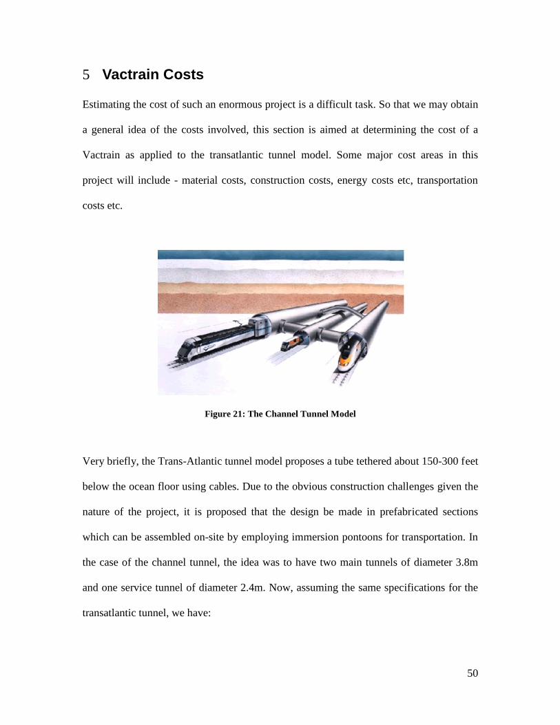
5 Vactrain Costs Estimating the cost of such an enormous project is a difficult task. So that we may obtain
a general idea of the costs involved, this section is aimed at determining the cost of a
Vactrain as applied to the transatlantic tunnel model. Some major cost areas in this
project will include - material costs, construction costs, energy costs etc, transportation
costs etc.
Figure 21: The Channel Tunnel Model
Very briefly, the Trans-Atlantic tunnel model proposes a tube tethered about 150-300 feet
below the ocean floor using cables. Due to the obvious construction challenges given the
nature of the project, it is proposed that the design be made in prefabricated sections
which can be assembled on-site by employing immersion pontoons for transportation. In
the case of the channel tunnel, the idea was to have two main tunnels of diameter 3.8m
and one service tunnel of diameter 2.4m. Now, assuming the same specifications for the
transatlantic tunnel, we have:

51
Tunnel Volume = (volume of 2 main tunnels) + (volume of service tunnel)
( ) ( )[ ] ( ) ( )[ ]( ) ( )[ ] ( ) ( )[ ]mmmm
hrhr3232
22
21
1092.55634.21092.55638.32
22
×××+××××
×××+×××
ππππ
= 605492311.6 m3
5.1 Vacuum costs
The proposed approach for evacuating the tube is to use an array of heavy duty vacuum
pumps. These pumps operate on the principle of using a column of liquid as a piston to
control airflow. There is great diversity in industrial vacuum pumps based on design,
rating, vacuum level, power consumption and capacity. In the absence of a set of more
specific customer requirements, we decided to go with the SK Water Ring Vacuum Pump
designed for industrial purposes. This product is made by Remy Valve Manufacturing
Co, a manufacturing firm based in Shanghai, China and has the following power/capacity
specifications. (Shanghai Remy ValveManufacturing Co.)
Figure 22 SK Water Ring Vacuum Pump
52
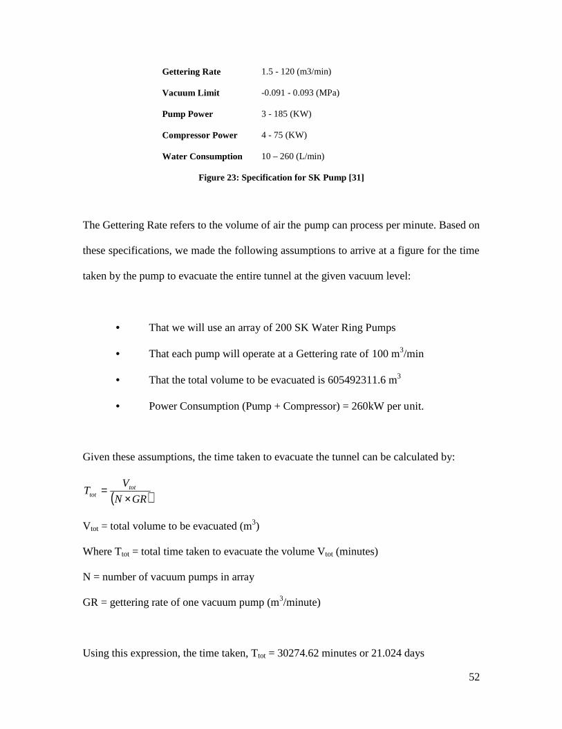
Gettering Rate 1.5 - 120 (m3/min)
Vacuum Limit -0.091 - 0.093 (MPa)
Pump Power 3 - 185 (KW)
Compressor Power 4 - 75 (KW)
Water Consumption 10 – 260 (L/min)
Figure 23: Specification for SK Pump [31]
The Gettering Rate refers to the volume of air the pump can process per minute. Based on
these specifications, we made the following assumptions to arrive at a figure for the time
taken by the pump to evacuate the entire tunnel at the given vacuum level:
• That we will use an array of 200 SK Water Ring Pumps
• That each pump will operate at a Gettering rate of 100 m3/min
• That the total volume to be evacuated is 605492311.6 m3
• Power Consumption (Pump + Compressor) = 260kW per unit.
Given these assumptions, the time taken to evacuate the tunnel can be calculated by:
( )GRN
VT tot
tot ×=
Vtot = total volume to be evacuated (m3)
Where Ttot = total time taken to evacuate the volume Vtot (minutes)
N = number of vacuum pumps in array
GR = gettering rate of one vacuum pump (m3/minute)
Using this expression, the time taken, Ttot = 30274.62 minutes or 21.024 days

53
In order to get an energy cost estimate for this operation, we used the current US national
energy cost average of $ 0.10120 per KWH and arrived at a bill of USD 2,657,200 for
going from normal pressure to full vacuum capacity in 21 days.
This analysis assumes that there is no leakage in the vacuum levels after the initial
evacuation process. However, in the actual design, some leakage may occur and this
would require the vacuum pump array to be used periodically in order to ensure the
desired vacuum levels.
Another approach that was being considered was to see if it would be feasible to operate
at a lower vacuum level (and therefore a lower maximum velocity for the Vactrain) such
that the costs for maintaining the vacuum levels be reduced. However, after conducting
the above analysis, it seems that the energy bill for creating the vacuum is not as high as
what was anticipated. Thus, the optimization of this parameter does not affect the overall
Vactrain bill significantly. With an estimated total cost of 1 trillion dollars (Wikipedia),
the electricity bill for evacuation purposes alone is a mere 0.000266 %.

54
5.2 Material Costs
Figure 24 An HRC Steel Coil
For a project of this magnitude, it is expected that material costs will be considerable.
One of the major costs will be that of the sheer tonnage of steel required to build the tube
tunnel. It is estimated that about 1 billion tons of steel will be required to for the Vactrain.
As of January 2007, the cost of per metric ton of Hot-Rolled-Coil steel is USD 747 (The
Steel Index). Ignoring the effects of inflation, the current cost estimate for the required
steel is a whopping USD 747 billion.
In estimating the cost of building such a tunnel, there are a multitude of other materials
that need to be considered - power lines and power transmission, outer super buoyant
foam coating, tether cables (and how deep they need to go till they hit the ocean floor),
temperature regulation systems and miscellaneous material costs. It will be difficult to
reach a reasonably accurate figure without first coming up with a detailed design.

55
6 Pricing of the Vactrain The pricing of a transportation system is a critical factor that generally has a huge impact
on its success. There are a number of objectives for setting a good fare price:
• Attracting the maximum number of passengers
• Generating the maximum revenue for the transportation agency
• Recovering the initial investment in a practical period of time
• Achieving specific goals such as improving the mobility of students,
seniors or business officials
It is not possible to fulfill all the objectives mentioned above to the fullest as there are
definitely going to be conflicts. For example, the first and the second objectives are
mutually conflicting. To attract the maximum number of passengers, the transportation
costs need to be really low. However doing that might severely dampen the revenue that
would be generated. Hence, equilibrium needs to be found that would generate high
revenue without losing out on a lot of passengers and that would be the biggest challenge
while pricing the Vactrain. Recovering the initial investment would also be tied up with
these two objectives, as there would be massive initial investment involved and they
would aim to get it back in span of 10-15 years.
As the main clientele for the Vactrain would be business executive for whom time is of
paramount importance, the Vactrain has to be priced accordingly. In other words, it
would be more appropriate to compare the possible Vactrain prices with Executive class
aircraft prices rather than with the Economy class prices. However, there are a lot of

56
other factors that need to be thoroughly examined before reaching a consensus on the
price of a Vactrain ticket. ( Economic Aspects of Transportation Systems)
6.1 Concorde In terms of Potential clientele, speed, saving time, initial investments and carrying
capacity Vactrain can be readily compared with a Concorde. In this section, we take a
look at the Concorde and relate how its pricing could be used as a measure for Vactrain
prices.
Figure 25 : Concorde flight operated by Air France
The Concorde flight was operated commercially by British Airways and Air France from
the year 1976 onwards. Concorde flights were able to travel at around 1500mph and the
flights from New York and Washington to London and Paris would take less than 3.5
hours. There were about 16 Concorde flights that traveled across the Atlantic Ocean
every day. These flights were also very comfortable to the passengers when compared
with the regular flights as shown in Figure 26Error! Reference source not found..
Commercially, these flights were a success until the year 2000 when a flight crashed in

57
Paris which had a huge impact on its business. The crash killed 100 people along with 9
of the crew. There was an immediate ban on the Concorde flights and they came back to
service from Oct 2001. However, it was never really a success thereafter and went into a
lot of losses eventually going out of service in the year 2003. Apart from the crash, the
Sept 11th terrorist attacks and the rising maintenance costs led to its ultimate withdrawal.
(Wikipedia)
Figure 26 : Inside the Concorde
The pricing of the Concorde was a costly affair. A round trip from New York to Paris
cost about $3800 and it bloated up to $8000 by the year 2000. The main reason for this
high pricing had to do with the large maintenance costs due to the fuel which was
expensive. It would cost both a Concorde and a regular Boeing 747 the same amount of
fuel but the Boeing could carry 4 times the passengers which made the difference. The
pricing of regular flights was around $500-$1,000 which was lower than the price of the
Concorde. However, the Concorde appealed to the elite people from the business
community for whom money did not make such a difference and the Concorde would
still make money from such audience. (Wikipedia)

58

59
6.2 Comparing Vactrain with the Concorde There are three main factors to keep in mind while comparing the pricing of the
Concorde with the possible pricing of the Vactrain. The major advantage that a Vactrain
has when compared to the Concorde is that its maintenance costs would be much lower.
Also, the Vactrain would be expected to have a much higher capacity than the Concorde.
The Concorde could fit a maximum of 100 passengers whereas the Vactrain would be
able to seat at least 800 passengers, assuming it is as big as the Euro-rail. However, the
initial investment of the Vactrain is expected to be much higher than that of the
Concorde. So, these would be the factors that would have to be considered before making
an estimate on the price of the Vactrain. It would not be possible to start off the Vactrain
with same price as the Concorde which was $8000 by the time it closed. Such high prices
are definitely not going to work at this time, as even the rich companies found it difficult
to justify spending ten times the amount as you would spend on a normal flight.
However, it cannot be priced as much as the current aircraft prices either, as it would be
difficult to recover the investment. Hence, there needs to be an equilibrium price of
around $3000-$4000 which would be valued by the passengers but it would also help you
recover the initial investment. Considering that the business class tickets of Trans-
Atlantic airlines cost around $3000, a starting fare of $3000-$4000 would be really
appealing for the select audience as you can reach the destination in a quarter of the time.

60
7 Safety of a Vactrain
Safety of a Vactrain will be an important factor which will come into play when
passengers consider using it. A Vactrain needs to achieve a certain standard to be
considered safe. As it is impossible to determine the safety of a Vactrain before it is
started, we approached this problem by determining the safety of an airplane and setting
that as a yardstick for Vactrain safety. We chose airplanes for comparing Vactrain safety
because, airplanes are currently the most superior modes of transportation and a Vactrain
being more superior in terms of saving time could replace airplanes in the future.
Safety is a subjective concept; its definition differs from person to person. Each person
looks at a different aspect while considering the safety of an airplane or a Vactrain. We
quantified safety of an airplane by calculating the death rate per passenger miles. For this,
we looked at the statistics of the number of fatal accidents in the world over the past
twenty years. The graph in Figure 27 shows the death rate per 100 million passenger
miles flown.

61
Figure 27 : Death rate in Aircrafts
As seen above, there are a lot of peaks and depressions but the overall trend is
downwards as indicated by the dashed line. The peaks are probably because an airplane
crash can lead to the death of all the passengers sometimes which causes the death rate to
shoot up. The downward trend is suggestive of improvement in technologies and
increased levels of safety. In 2005, the death rate per 100 million passenger miles was
0.03. Therefore, for a Vactrain to be an acceptable mode of transportation, the death rate
should be less than or equal to 0.03 per 100 million passenger miles when it is started.
Next, we used the slope of the regression line to calculate the decrease in death rate per
year. Using this line, the death rate was 0.073 per 100 million passengers in 1990 and
0.07 in 1991. Thus the death rate decreased by 0.003 per year.
Hence the death rate decreased by 0.03 from 1990 to 2000. Thus a Vactrain would be
considered a superior mode of transport in terms of improvement in safety levels if the
Death rate in Aircrafts
0
0.02
0.04
0.06
0.08
0.1
1985 1990 1995 2000 2005 2010
Years
Dea
th R
ate

decrease in death rate is more than 0.003 per year provided its death rate is less than or
equal to 0.03 per 100 million passenger miles at the time of its introduction.
We also looked at the trend of fatalities and death rates in the past decades of other more
commonly used modes of transport, railways and automobiles. The graph below shows
the death rate per 100 million vehicle miles in automobiles. The graph was plotted using
data obtained from the U.S. National Highway Traffic Safety Administration.
The graph below shows the passenger deaths in trains in the U.S. over the last 20 years.
Fatalities in
0
0.
1
1.
2
2.
3
3.
1975 198
Figure
Figure
se in death rate is more than 0.003 per year provided its death rate is less than or
equal to 0.03 per 100 million passenger miles at the time of its introduction.
We also looked at the trend of fatalities and death rates in the past decades of other more
commonly used modes of transport, railways and automobiles. The graph below shows
the death rate per 100 million vehicle miles in automobiles. The graph was plotted using
data obtained from the U.S. National Highway Traffic Safety Administration.
The graph below shows the passenger deaths in trains in the U.S. over the last 20 years.
Fatalities in Automobiles
1985 199 1995 200 2005 2010
Years
Figure 28 : Fatalities in Automobiles
Figure 29 : Fatalities in Railways
62
se in death rate is more than 0.003 per year provided its death rate is less than or
We also looked at the trend of fatalities and death rates in the past decades of other more
commonly used modes of transport, railways and automobiles. The graph below shows
the death rate per 100 million vehicle miles in automobiles. The graph was plotted using
The graph below shows the passenger deaths in trains in the U.S. over the last 20 years.

63
As seen in the above two graphs, there is a downward trend in both the graphs showing
that the overall number of deaths have decreased over the past twenty years. This could
be because the death rate reduced due to the improvement in technologies and heightened
safety. This is also applicable to a Vactrain. The data used to plot these graphs are U.S.
statistics. Similar trends can be observed in case of worldwide fatalities. The death rates
might be different but the trend is downward in the last twenty years. Through all these
analyses, we can conclude the following:
1. The death rate should be 0.03 per 100 million passenger miles or less at
the time the Vactrain is introduced.
2. For the Vactrain to replace aircrafts and establish its superiority, the
decrease in death rate should be more than or equal to 0.003 per 100 million
passenger miles per year.
3. The death rate might be more when the Vactrain is introduced but it will
probably decline steadily with time as the technology improves.
If these criteria are satisfied the Vactrain will universally be accepted as a safe mode of
transportation.

64
8 The Swissmetro In this section, we look at the Swissmetro project. The Swissmetro is a project that should
be implemented in the next 20 years if everything goes according to plan. The Swiss
metro is a maglev train that would run underground in partial vacuum connecting major
cities across Switzerland. There would be a train leaving every 6 minutes making it a
high frequency- high speed train.
Figure 30: The Swissmetro
8.1 Need for the project The reason an underground partial vacuum maglev train is extremely relevant for
Switzerland is the topography of the landscape. A fast moving maglev would be useful in
any country but it is all the more valuable in Switzerland. The Alps and the Jura
mountains cover about 70 percent of the surface of Switzerland. A majority of the
population of Switzerland, roughly 5 million, live in the Swiss Plateau which covers the
major landscape besides the mountains. (Study of the Swissmetro (1994-1998)) In such
topographical conditions, it is highly difficult to build a new efficient High Speed

65
Railroad. Hence the Swissmetro project gains more importance and relevance.
Figure 31: Possible Routing Map The first and the most important stage of the project is the line from Geneva to St.Gallen
through Lausanne, Bern, Luzern and Zurich (illustrated by the bold red line). The
Swissmetro is targeted to have a seating capacity of 200 persons. There would be a train
leaving every 6 minutes, which means about 2000 people would be travelling every hour
in each direction. Also, based on the requirement, the frequency might be reduced to 4
minutes, which would increase the capacity to 3000 persons. If everything goes
according to plan, one can get from Geneva to St.Gallen in an hour on the Swissmetro
compared to the 4 hours it takes now. For the initial part of the project, the line between
Geneva and Lausanne would be built first. (Swiss Metro Official Website)

66
8.2 Historical Timeline The historical timeline for the project is given below.
1974 – The Swissmetro project was conceived by Rodolphe Neith
1985 – The project was presented at the parliament
1986 – A feasibility study of the project is done and the Upper House of Parliament
rejects the proposal
1992 – A new promotion company Swissmetro AG is established in Berne
1997 – Swissmetro AG requests a contract for building of a pilot distance
1999 – The Upper House of Parliament decides that contract approval will be considered
only if there is financing proof
2000 – Swissmetro is certified to be about 5 times more ecological than air traffic
2002 – The Upper House of the Parliament wants the Swissmetro project to be pursued
further
2003 – Swissmetro resubmits a request for the contract of a pilot distance (from Geneva
to Lausanne) with financial and budget evaluation. The project budget was approximated
to be around 3.5 billion Francs
2004 – Mathematical models and Simulations with 3-d levels are tested and found
feasible
2006 – Swissmetro starts plans to market the technology developments in the project
(Wikipedia)

67
8.3 Implications of the successful implementation of Swissmetro
A successful implementation of the Swissmetro will have many far reaching effects.
There would definitely be a huge economic impact and the economic situation would
take an upsurge. Looking ahead, there would definitely be plans of building a metro that
would connect all the major cities in Europe which would go a long way in the
development of Europe in general.
Figure 32: A model of the underground vacuum train
The Swissmetro is therefore a very exciting project that would also be of great interest to
someone examining the feasibility of a Vactrain. If the Swissmetro which is based on
partial vacuum is successful, it is extremely likely that a complete vacuum train would be
the next step that would be looked at.
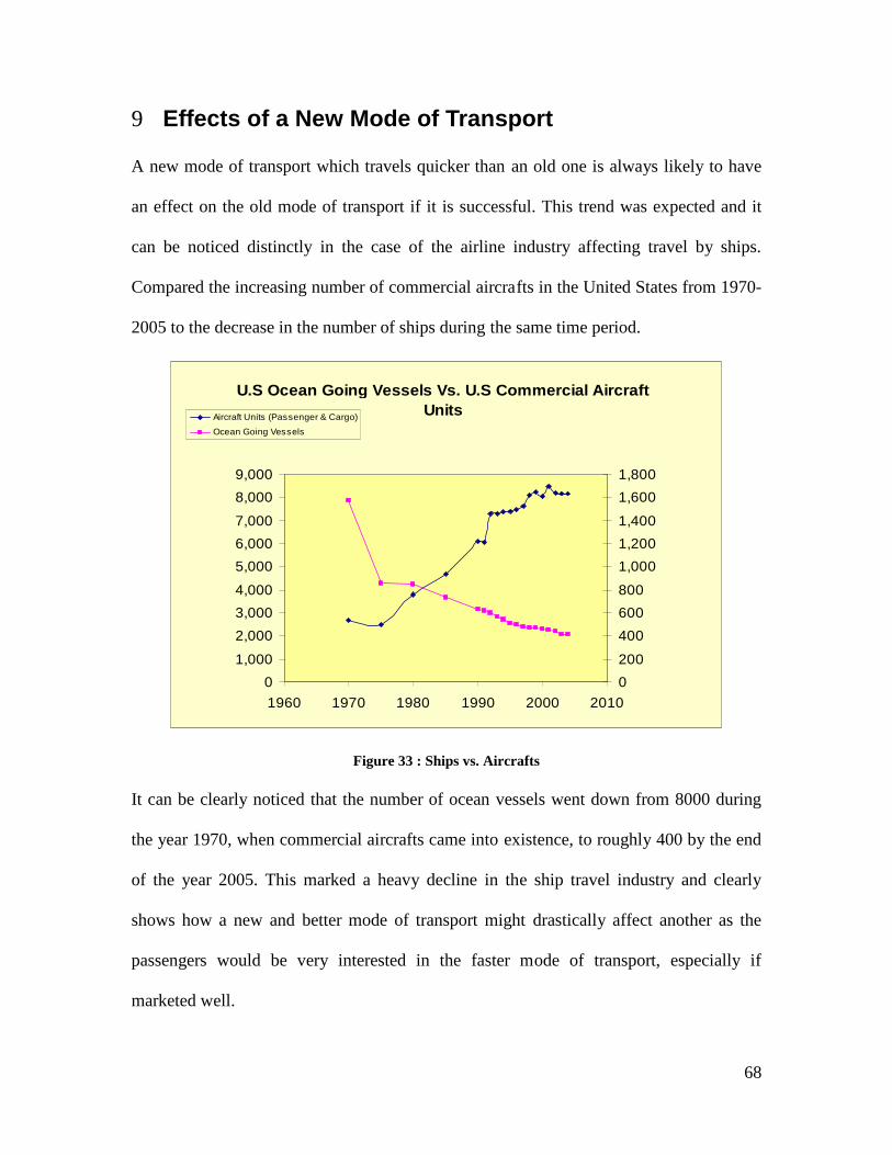
68
9 Effects of a New Mode of Transport A new mode of transport which travels quicker than an old one is always likely to have
an effect on the old mode of transport if it is successful. This trend was expected and it
can be noticed distinctly in the case of the airline industry affecting travel by ships.
Compared the increasing number of commercial aircrafts in the United States from 1970-
2005 to the decrease in the number of ships during the same time period.
Figure 33 : Ships vs. Aircrafts It can be clearly noticed that the number of ocean vessels went down from 8000 during
the year 1970, when commercial aircrafts came into existence, to roughly 400 by the end
of the year 2005. This marked a heavy decline in the ship travel industry and clearly
shows how a new and better mode of transport might drastically affect another as the
passengers would be very interested in the faster mode of transport, especially if
marketed well.
U.S Ocean Going Vessels Vs. U.S Commercial Aircraft Units
0
1,000
2,000
3,000
4,000
5,000
6,000
7,000
8,000
9,000
1960 1970 1980 1990 2000 2010
0
200
400
600
800
1,000
1,200
1,400
1,600
1,800
Aircraft Units (Passenger & Cargo)
Ocean Going Vessels
69
10 Conclusion In this project, we have tried to consolidate the idea of the Vactrain from its
conceptualization in 1945 by Robert Goddard as a university student to its current status
and future implications. We analyzed the practicability of a Vactrain and how it would
impact the world. In the world of today, where distances are no longer a constraint to
communication, the next expected step is high speed travel.
The Vactrain outweighs the current modes of transport in several ways, making it a
ground-breaking idea. It has a clear edge over present airplanes, trains and automobiles as
it causes no pollution and does not operate with gas or petroleum. Thus, while the present
transportation would soon be in a sticky situation with the energy crises which the world
is facing with dwindling resources of petroleum and gas, the Vactrain would emerge
victorious. Moreover, the Vactrain is unaffected by any extremes in weather conditions.
It has low maintenance costs as it employs the high-lifetime maglev technology, which
also minimized wear due to friction. Additionally, it has low operation costs and 25%
energy consumption when compared to aircrafts. Due to all these factors, the Vactrain
triumphs over the current means not just in the future but even in present situations
making it highly superior.
A Vactrain has several advantages which make it a revolutionary idea but it is not
without its set of drawbacks which are preventing it from turning into reality. Although
proposed in 1945, the Vactrain is yet to be built. This is not because the technology is not
available, but because of the huge manufacturing bill of one trillion dollars tagged to it.
70
Ironically, delaying the Vactrain would only make this problem bigger. This is indicated
by the fact, that at the time of its proposal, its estimated manufacturing cost was much
smaller.
The Vactrain would involve building a huge tunnel, which would be more feasible, in
terms of costs and time, under the sea than underground. Additionally, an underground
tunnel would be more susceptible to collapse in the event of an earthquake. The safety of
a Vactrain is another huge issue which makes this investment a huge risk.
Several factors will govern a Vactrain’s design such as aerodynamic drag issues,
passenger comfort, passenger safety and the vacuum level maintained. One of the things
considered was the trade-off between cost and vacuum level maintained. Based on our
study, it was seen that the energy cost for maintaining a high vacuum level in the tube
does not substantially affect the overall expenditure for the Vactrain.
Moreover, higher the speed, more the aerodynamic drag associated with it. Therefore,
optimum values of time taken for a trip, desirable speed and affordable costs need to be
determined and a balance has to be attained between them. Depending on these, the
degree of the vacuum needed to be created can be determined. Also, as discussed earlier,
the Vactrain can achieve a high speed by accelerating gradually without affecting the
passengers comfort in any drastic way.

71
It is thus safe to say that if the Vactrain becomes a reality, it will lead to a decline in the
most superior mode of transport at present, namely aircrafts. And similar to the transition
from water-vessel to airplanes, the Vactrain might be even be a substitute for certain
routes. Not only is the Vactrain much faster but also overcomes most of the
disadvantages of aircrafts and other modes of transport. Initially, the ticket prices might
prevent a wide clientele, but over time, these issues can be fixed and the Vactrain could
possibly be the next big step in the transportation industry.
72
11 Bibliography Economic Aspects of Transportation Systems. About.com. Magnetin Levitation - Background. 15th January 2007 <http://inventors.about.com/library/inventors/blrailroad3.htm>. Arturo Baron, Michele Mossi, Stefano Sibilla. "The Alleviation of Aerodynamic Drag and Wave Effects of high-speed trains in very long tunnels." September 2000. Census, US. Motor Vehicle Accidents - Numbers and Deaths. <http://www.census.gov/compendia/statab/tables/07s1082.xls>. —. Worldwide Airline Fatalities 1806 - 2005. <http://www.census.gov/compendia/statab/tables/07s1052>. Freeman, Richard. The Science of Maglev. 1993. <www.//american_almanac.tripod.com/maglev.htm>. Home.no. World's Longest Railway Tunnels. <http://home.no.net/lotsberg/data/rail.html>. International Conference on Magnetically Levitated Systems. 20th January 2007 <http://www.maglev2006.de/139_Tielkes/139_Tielkes_ok.pdf>. International Union of Railways. International Union of Railwals. 15th January 2007 <http://www.uic.asso.fr/gv/article.php3?id_article=14>. Jacobs, Jonathan. Magnetic Levitation: Transportation for the 21st Century. April 2002. <http://www.hcs.harvard.edu/~hsr/pdfsspring2002/jacobs52-56.pdf>. Keating, Oliver. High Speed Rail. 15th January 2007 <http://www.o-keating.com/hsr/>. Larry Johnson, Science Direct. "Application of HTSC's to Magnetically Levitated Trains." Science Direct LIGO. LIGO Hansford Observatory News. <http://www.ligo.caltech.edu/LIGO_web/9811news/9811han.html>. Mag, Hafta. Hafta Mag. June 2006. November 2006 <http://www.haftamag.com/content/view/187/43/>. Powell, James. The New Mode of Transportation for the 21st Century. April 2002. <http://www.21stcenturysciencetech.com/articles/Summer03/maglev2.html>. Quest, NASA. Effects of High Speed and Acceleration on the Human Body. <http://quest.nasa.gov/saturn/qa/new/Effects_of_speed_and_acceleration_on_the_body.txt>.

73
Shanghai Remy ValveManufacturing Co. Shanghai Remy ValveManufacturing Co. Vacuum Pumps. <http://rmpv.com/EN_web/PRO_pump/vacuum_pump.htm>. Skytran.net. High Speed Effects of Drag. <http://www.skytran.net/04Technical/pod09.htm>. Study of the Swissmetro (1994-1998). <http//swissmetro.ch/downloads/studien/schlussbericht_eng.pdf>. Swiss Metro Official Website. Swiss Metro Official Website. <http://www.swissmetro.ch/eng-home-startseite.html>. Th. Tielkes, Deutsche Balm. Departments of Aerodynamics and Air Conditioning, Munich, Germany. <http://www.maglev2006.de/139_Tielkes/139_Tielkes_ok.pdf>. The Steel Index. The Steel Index. <http://www.thesteelindex.com/?cid=10>. Tunnel.no. Norwegian Technique of Tunnneling . <http://www.tunnel.no/>. Tunneling, Japan. Japan Tunneling. <http://www.soc.nii.ac.jp/jta/nttj/statistical_data/index2.html>. Voshell, Martin. "High Acceleration and the Human Body." 28th November 2004. <http://csel.eng.ohio-state.edu/voshell/gforce.pdf>. Wikipedia. Concorde. <http://en.wikipedia.org/wiki/Concorde>. —. G Force. <http://en.wikipedia.org/G-force>. —. Magnetic Levitation Train. <http://en.wikipedia.org/wiki/Magnetic_Levitation_Train>. —. Swissmetro [translated]. <http://translate.google.com/translate?hl=en&sl=de&u=http://de.wikipedia.org/wiki/Swissmetro&sa=X&oi=translate&resnum=7&ct=result&prev=/search%3Fq%3Dswissmetro%26hl%3Den>. —. Tunnels. <http://en.wikipedia.org/wiki/Tunnel>. —. Vactrain. 2nd December 2006 <http://en.wikipedia.org/wiki/Vactrain>.
Economic Aspects of Transportation Systems.

74
About.com. Magnetin Levitation - Background. 15th January 2007 <http://inventors.about.com/library/inventors/blrailroad3.htm>. Arturo Baron, Michele Mossi, Stefano Sibilla. "The Alleviation of Aerodynamic Drag and Wave Effects of high-speed trains in very long tunnels." September 2000. Census, US. Motor Vehicle Accidents - Numbers and Deaths. <http://www.census.gov/compendia/statab/tables/07s1082.xls>. —. Worldwide Airline Fatalities 1806 - 2005. <http://www.census.gov/compendia/statab/tables/07s1052>. Freeman, Richard. The Science of Maglev. 1993. <www.//american_almanac.tripod.com/maglev.htm>. Home.no. World's Longest Railway Tunnels. <http://home.no.net/lotsberg/data/rail.html>. International Conference on Magnetically Levitated Systems. 20th January 2007 <http://www.maglev2006.de/139_Tielkes/139_Tielkes_ok.pdf>. International Union of Railways. International Union of Railwals. 15th January 2007 <http://www.uic.asso.fr/gv/article.php3?id_article=14>. Jacobs, Jonathan. Magnetic Levitation: Transportation for the 21st Century. April 2002. <http://www.hcs.harvard.edu/~hsr/pdfsspring2002/jacobs52-56.pdf>. Keating, Oliver. High Speed Rail. 15th January 2007 <http://www.o-keating.com/hsr/>. Larry Johnson, Science Direct. "Application of HTSC's to Magnetically Levitated Trains." Science Direct LIGO. LIGO Hansford Observatory News. <http://www.ligo.caltech.edu/LIGO_web/9811news/9811han.html>. Mag, Hafta. Hafta Mag. June 2006. November 2006 <http://www.haftamag.com/content/view/187/43/>. Powell, James. The New Mode of Transportation for the 21st Century. April 2002. <http://www.21stcenturysciencetech.com/articles/Summer03/maglev2.html>. Quest, NASA. Effects of High Speed and Acceleration on the Human Body. <http://quest.nasa.gov/saturn/qa/new/Effects_of_speed_and_acceleration_on_the_body.txt>. Shanghai Remy ValveManufacturing Co. Shanghai Remy ValveManufacturing Co. Vacuum Pumps. <http://rmpv.com/EN_web/PRO_pump/vacuum_pump.htm>. Skytran.net. High Speed Effects of Drag. <http://www.skytran.net/04Technical/pod09.htm>. Study of the Swissmetro (1994-1998). <http//swissmetro.ch/downloads/studien/schlussbericht_eng.pdf>. Swiss Metro Official Website. Swiss Metro Official Website. <http://www.swissmetro.ch/eng-home-startseite.html>. Th. Tielkes, Deutsche Balm. Departments of Aerodynamics and Air Conditioning, Munich, Germany. <http://www.maglev2006.de/139_Tielkes/139_Tielkes_ok.pdf>. The Steel Index. The Steel Index. <http://www.thesteelindex.com/?cid=10>. Tunnel.no. Norwegian Technique of Tunnneling . <http://www.tunnel.no/>. Tunneling, Japan. Japan Tunneling. <http://www.soc.nii.ac.jp/jta/nttj/statistical_data/index2.html>. Voshell, Martin. "High Acceleration and the Human Body." 28th November 2004. <http://csel.eng.ohio-state.edu/voshell/gforce.pdf>.

75
Wikipedia. Concorde. <http://en.wikipedia.org/wiki/Concorde>. —. G Force. <http://en.wikipedia.org/G-force>. —. Magnetic Levitation Train. <http://en.wikipedia.org/wiki/Magnetic_Levitation_Train>. —. Swissmetro [translated]. <http://translate.google.com/translate?hl=en&sl=de&u=http://de.wikipedia.org/wiki/Swissmetro&sa=X&oi=translate&resnum=7&ct=result&prev=/search%3Fq%3Dswissmetro%26hl%3Den>. —. Tunnels. <http://en.wikipedia.org/wiki/Tunnel>. —. Vactrain. 2nd December 2006 <http://en.wikipedia.org/wiki/Vactrain>.