feasibility study of installing online vibration ... · system 1 software is integrated into a...
TRANSCRIPT
1
FEASIBILITY STUDY OF INSTALLING ONLINE VIBRATION
MONITORING AND ANALYSIS SYSTEM IN AN LNG PLANT
(GE SYSTEM1)
A Dissertation
Presented to
The Engineering Institute of Technology
by
Kannan Periyaiya
In Partial Fulfillment
of the Requirements for the Degree
Master of Engineering in
INDUSTRIAL AUTOMATION
JULY 2017
COPYRIGHT © 2017 BY KANNAN PERIYAIYA

2
ACKNOWLEDGEMENTS
I would like to express my sincere gratitude to my supervisor Robert Holm for
providing me with constant support and guidance during the entire research process.
Furthermore, I would like to thank EIT, my professors, friends, and family for the
continuous support during the research. They all contributed to enhance my
knowledge on the research topic. Finally, I would also like to thank the professionals
from the gas plant who helped me by participating in the survey. All their support
inspired and enlightened me to go through the research process. This research
enhanced my knowledge and skills and provided an opportunity to face new
challenges.
3
TABLE OF CONTENTS
Acknowledgments.......................................................................................................... 2
List of Tables ................................................................................................................. 6
List of Figures ................................................................................................................ 7
Abstract .......................................................................................................................... 8
Chapter 1. Introduction .................................................................................................. 9
1.1 Introduction ....................................................................................................... 9
1.2 Acronyms and definitions ............................................................................... 10
1.3 Background of the research ............................................................................ 11
1.3.1 Common major safety issues in an LNsG Plant ...................................... 11
1.3.2 Current site issues without online condition monitoring (CM) ............... 12
1.4 Research aims and objectives ......................................................................... 13
1.5 Research questions .......................................................................................... 14
1.6 Research problem............................................................................................ 15
1.7 Justification for the research ........................................................................... 16
1.8 Methodology ................................................................................................... 16
1.9 Research outline .............................................................................................. 17
1.10 Summary .......................................................................................................... 17
Chapter 2. Literature review and conceptual framework ............................................. 19
2.1 Introduction ..................................................................................................... 19
2.2 Conceptual framework for the research study ................................................ 20
2.3 Overview of the proposed system ................................................................... 21
2.3.1 Bently Nevada 3500 ................................................................................. 21
2.3.2 Bently Nevada 1701 ................................................................................. 22
2.3.3 System 1 condition monitoring system in gas plant ................................ 23
2.3.5 Network hardware requirements .............................................................. 27
4
2.3.7 Software Configuration ............................................................................ 35
2.3.8 BN1701 Software Configuration ............................................................. 36
2.3.9 Gas plant condition monitoring philosophy ............................................. 37
2.3.10 Existing Systems ...................................................................................... 38
2.3.11 Desired System ........................................................................................ 41
2.4 Features of the System 1 condition monitoring software ............................... 42
2.5 Improvement in safety issues by using System 1 condition monitoring
system ............................................................................................................... 43
2.6 Improvements in production loss and maintenance issues by using System 1
condition monitoring system. ........................................................................... 46
2.7 Summary ......................................................................................................... 47
Chapter 3. Research methodology ............................................................................... 48
3.1 Introduction ..................................................................................................... 48
3.2 Research philosophy ....................................................................................... 48
3.3 Data Collection procedures and techniques .................................................... 49
3.3.1 Data sources ............................................................................................. 50
3.4 Sample and population .................................................................................... 50
3.5 Gantt chart for the research study ................................................................... 51
3.6 The Adopted research strategy........................................................................ 51
Chapter 4. Findings and discussion ............................................................................. 53
4.1 Introduction ..................................................................................................... 53
4.2 Data analysis and findings .............................................................................. 53
4.3 Discussion and Conclusion ............................................................................. 66
Chapter 5. Conclusions and recommendations ............................................................ 68
5.1 Summary ......................................................................................................... 68
5.2 Conclusions about the research problem ........................................................ 68
5.3 Implications for theory .................................................................................... 69
5.4 Recommendations ........................................................................................... 69

5
5.5 Areas of further study ..................................................................................... 70
References .................................................................................................................... 72
Appendices ................................................................................................................... 79
1. Survey Questionnaire ............................................................................................... 79
6
LIST OF TABLES
Table 1 DIN mounted equipment in rack 33CPW-CAR-07 in the CAR ..................... 30
Table 2 DIN mounted equipment in a 19 inch rack in the Central Auxiliary Room ... 35
Table3.Contract engineering support labour charge-out rates ..................................... 39
Table 4 Contract engineering support labour charge-out rates .................................... 40
Table 5 Improvement in safety issues by use of system 1 condition monitoring
system .................................................................................................................. 45
Table 6 Gantt chart....................................................................................................... 51
Table 7 No of years working in gas plant .................................................................... 54
Table 8 Satisfied with the existing condition monitoring software of gas plant ......... 55
Table 9 Agree with the decision to install System 1 condition monitoring software .. 56
Table 10 Agree that the proposed system will meet the business requirements .......... 58
Table 11 Agree with maintenance of standardization of the software is crucial ......... 59
Table 12 Agree that the proposed system helps to increase the reliability in the gas
plant...................................................................................................................... 61
Table 13 Agree that the System 1 condition monitoring system should give real time
information to the users ....................................................................................... 62
Table 14 Agree with implementation of system 1 condition monitoring software in
gas plant will reduce the safety issues ................................................................. 64
Table 15 Proposed system has encountered a sudden rise in the production .............. 65
7
LIST OF FIGURES
Figure 1 Conceptual Framework for the research study .............................................. 21
Figure 2 Data flow from BN probe to BN rack ........................................................... 22
Figure 3 Principal System 1 software components and data flow paths ...................... 24
Figure 4 VLAN approach to connect a single BN unit to the System 1 server ........... 32
Figure 5 LAN approach to connect a single BN unit to the System 1 server .............. 34
Figure 6 Current ‘semi-online’ vibration data monitoring strategy ............................. 40
Figure 8 Implementation of Condition monitoring system.......................................... 44
Figure 9 Three types of research philosophy ............................................................... 49
Figure 10 No of years working in gas plant ................................................................. 54
Figure 11 Level of satisfaction with the existing condition monitoring software of gas
plant...................................................................................................................... 55
Figure 12 Agree with the decision to install System 1 condition monitoring software
.............................................................................................................................. 56
Figure 13 Agree that the proposed system will meet the business requirements ........ 58
Figure 14 Agree with maintenance of standardization of the software is crucial ........ 60
Figure 15 Agree that the proposed system helps to increase the reliability in the gas
plant...................................................................................................................... 51
Figure 16 Agree that the System 1 condition monitoring system should give real time
information to the users ....................................................................................... 63
Figure 17 Agree with implementation of system 1 condition monitoring software in
gas plant will reduce the safety issues ................................................................. 64
Figure 18 Proposed system has encountered a sudden rise in the production ............. 66
8
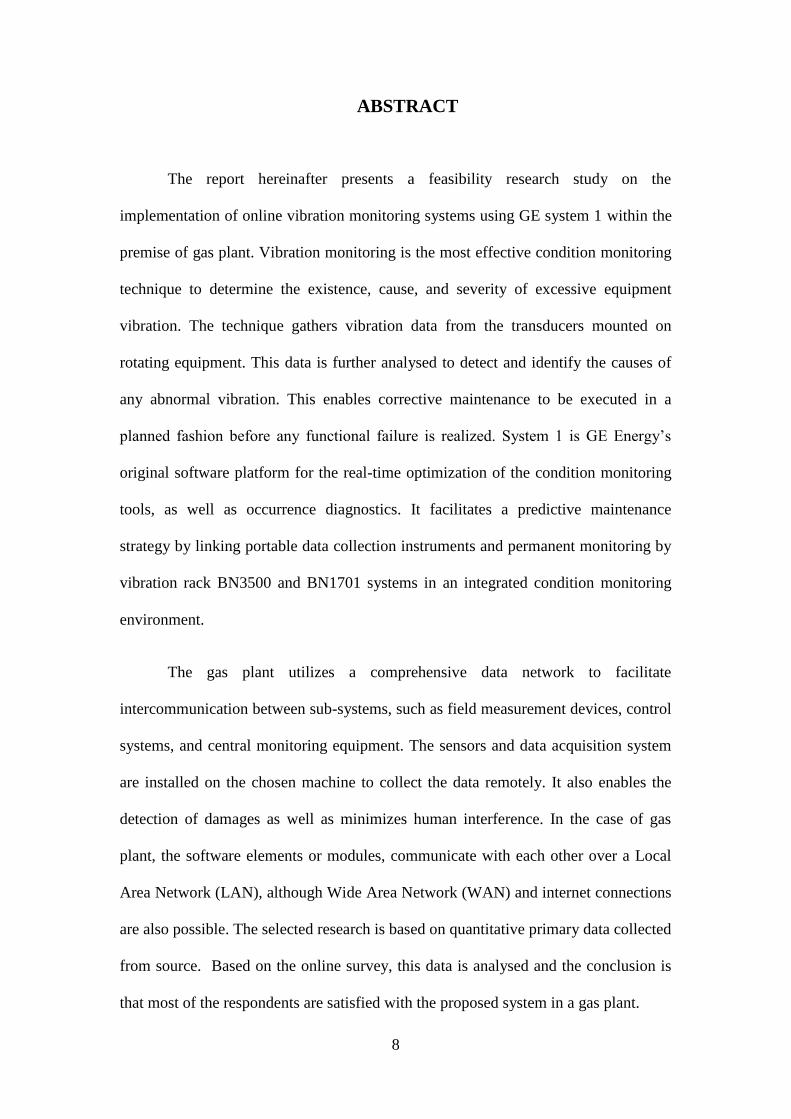
ABSTRACT
The report hereinafter presents a feasibility research study on the
implementation of online vibration monitoring systems using GE system 1 within the
premise of gas plant. Vibration monitoring is the most effective condition monitoring
technique to determine the existence, cause, and severity of excessive equipment
vibration. The technique gathers vibration data from the transducers mounted on
rotating equipment. This data is further analysed to detect and identify the causes of
any abnormal vibration. This enables corrective maintenance to be executed in a
planned fashion before any functional failure is realized. System 1 is GE Energy’s
original software platform for the real-time optimization of the condition monitoring
tools, as well as occurrence diagnostics. It facilitates a predictive maintenance
strategy by linking portable data collection instruments and permanent monitoring by
vibration rack BN3500 and BN1701 systems in an integrated condition monitoring
environment.
The gas plant utilizes a comprehensive data network to facilitate
intercommunication between sub-systems, such as field measurement devices, control
systems, and central monitoring equipment. The sensors and data acquisition system
are installed on the chosen machine to collect the data remotely. It also enables the
detection of damages as well as minimizes human interference. In the case of gas
plant, the software elements or modules, communicate with each other over a Local
Area Network (LAN), although Wide Area Network (WAN) and internet connections
are also possible. The selected research is based on quantitative primary data collected
from source. Based on the online survey, this data is analysed and the conclusion is
that most of the respondents are satisfied with the proposed system in a gas plant.
9
CHAPTER 1 INTRODUCTION
1.1 Introduction
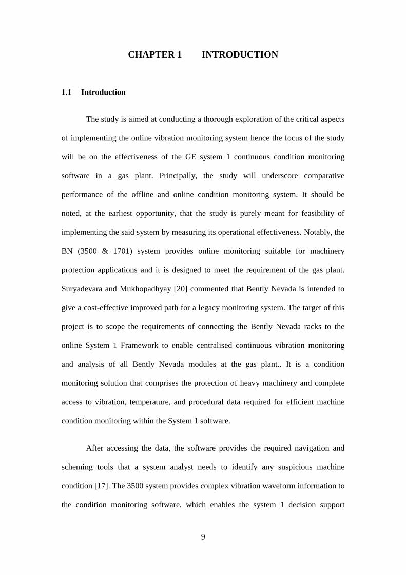
The study is aimed at conducting a thorough exploration of the critical aspects
of implementing the online vibration monitoring system hence the focus of the study
will be on the effectiveness of the GE system 1 continuous condition monitoring
software in a gas plant. Principally, the study will underscore comparative
performance of the offline and online condition monitoring system. It should be
noted, at the earliest opportunity, that the study is purely meant for feasibility of
implementing the said system by measuring its operational effectiveness. Notably, the
BN (3500 & 1701) system provides online monitoring suitable for machinery
protection applications and it is designed to meet the requirement of the gas plant.
Suryadevara and Mukhopadhyay [20] commented that Bently Nevada is intended to
give a cost-effective improved path for a legacy monitoring system. The target of this
project is to scope the requirements of connecting the Bently Nevada racks to the
online System 1 Framework to enable centralised continuous vibration monitoring
and analysis of all Bently Nevada modules at the gas plant.. It is a condition
monitoring solution that comprises the protection of heavy machinery and complete
access to vibration, temperature, and procedural data required for efficient machine
condition monitoring within the System 1 software.
After accessing the data, the software provides the required navigation and
scheming tools that a system analyst needs to identify any suspicious machine
condition [17]. The 3500 system provides complex vibration waveform information to
the condition monitoring software, which enables the system 1 decision support
10
software to identify faults in the machinery in the real time for vital consumer assets.
The degree to which acquired data is analysed at the gas plant depends on the
criticality and type of monitored equipment [43]. It is envisaged that criticality level-
A and level-B machines on the gas plant will be continuously monitored for vibration
data using an online condition monitoring system.
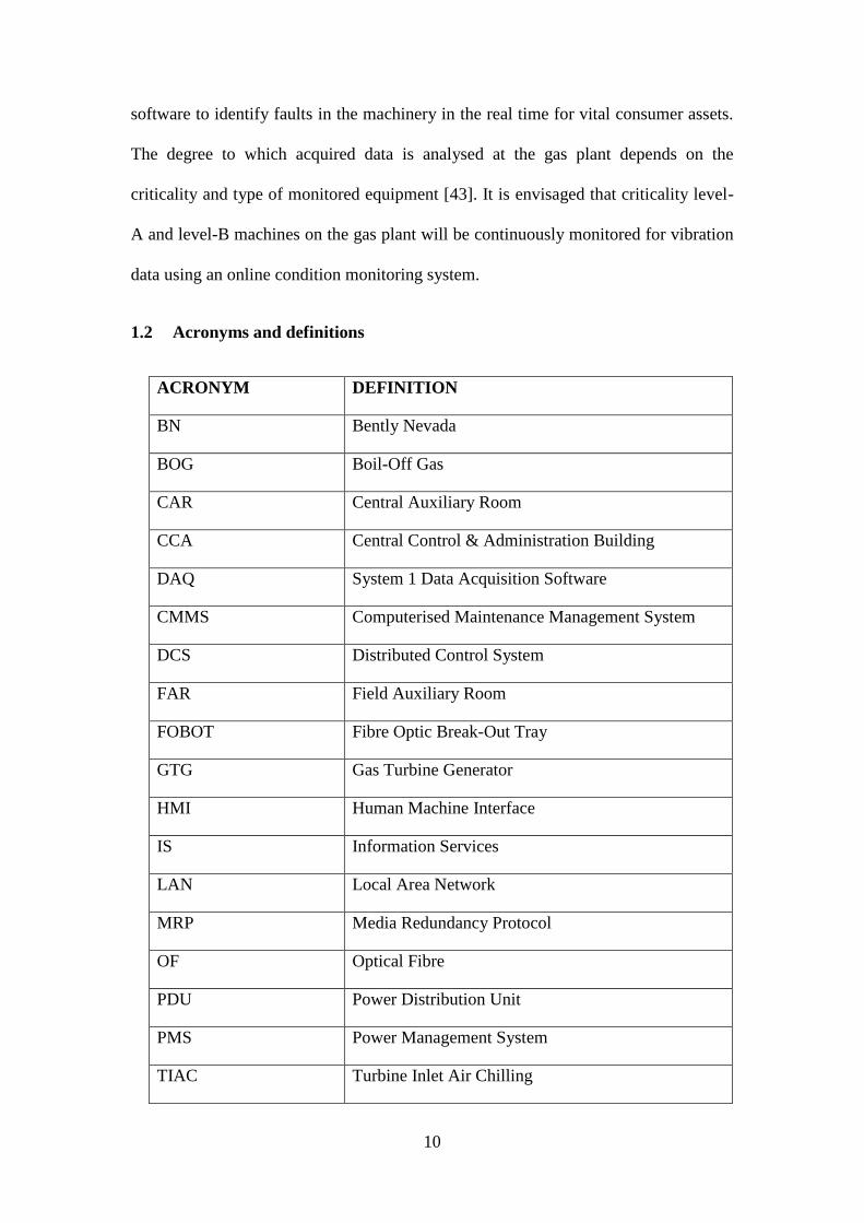
1.2 Acronyms and definitions
ACRONYM DEFINITION
BN Bently Nevada
BOG Boil-Off Gas
CAR Central Auxiliary Room
CCA Central Control & Administration Building
DAQ System 1 Data Acquisition Software
CMMS Computerised Maintenance Management System
DCS Distributed Control System
FAR Field Auxiliary Room
FOBOT Fibre Optic Break-Out Tray
GTG Gas Turbine Generator
HMI Human Machine Interface
IS Information Services
LAN Local Area Network
MRP Media Redundancy Protocol
OF Optical Fibre
PDU Power Distribution Unit
PMS Power Management System
TIAC Turbine Inlet Air Chilling
11
TCP/IP Transmission Control Protocol/Internet Protocol
VLAN Virtual Local Area Network
1.3 Background of the research
The research reflects on connecting Bently Nevada vibration racks with the
GE System 1 monitoring software to enable continuous monitoring. The System 1
software designed to help in the optimization of equipment, condition monitoring, and
event diagnostics [18]. The client-based architecture is scalable and flexible. The
System 1 software is integrated into a single system with a common database
structure. Notably, the connection of Bently Nevada with the System 1 platform
enables the mechanical reliability and process engineers, operators, and other plant
personnel to identify and respond to events in order to optimize the business impact
[27]. The existing Bently Nevada 3500 system is represented over 50 years of the
Bently Nevada machinery protection [45]. Best practice machinery is built on highly
flexible as well as scalable rack based platform. Furthermore, the current 3500
systems were unrestricted as it includes a little subset of observe versions, which
subsists today [19]. The initial release is focused on giving advanced, stretchy, and
dependable vibration data based on the machines’ protection obtainable at the time. It
also provides simple and critical protection to machinery from catastrophic failure,
which results in environmental safety concerns and significant loss of production.
1.3.1 Common major safety issues in an LNG Plant
The cost of downtimes due to unprecedented shutdowns and poorly scheduled
maintenance program are among the leading causes of cost overshoots in the gas
plant. Notably, compressor failures, for instance, can lead to production loss up to
12
AUD5 million/day. Yun [39] argues that extraordinary operating conditions of the
compressor are to blame for the operational disruption. Predisposing conditions such
as blocked heat exchanger surfaces may pose great safety risk to the system and the
operators at large; normally, it will translate into systemic heat overload and thereafter
pressure overloads. Besides, uncontrolled release of pressure energy (due to internal
overbearing pressure) can result in punctures, lacerations, crushing and even death.
Furthermore, parts of the equipment could also be propelled over great distances,
causing injury and damage to people, the environment, and buildings hundreds of
metres away. In a nutshell, should the due safety procedure not be followed to the
letter, certainly, the following Specific HSE hazards associated with
turbine/compressor area could result:
High pressure feed gas and liquid streams jetting to the furthest distances thus
causing injuries not only to the plant operators but the neighbouring buildings
Low temperature streams and equipment – Cryogenic Processes
High temperature streams and equipment mainly due to heat exchanger failure
can cause unprecedented explosions and ultimately fires
Noise leading to permanent hearing damage to the gas plant operators
Rotating equipment under catastrophic failure conditions implicitly may eject
high kinetic energy shrapnel
Nitrogen liquid leaks due to the cracked vessels causing harm
Mineral and synthetic lubrication oils leaking and causing harm
Leak of flammable gases from piping and joints causing fires
1.3.2 Current site issues without online condition monitoring (CM)
There are frequent Emergency Shutdown System (ESD) trips caused by
package heavy equipment failures. Further, inadequate failure analyses are conducted.
(Offline vibration data collection only ever gives a snapshot in time of machinery
performance)
13
The largest cost of continuing with an offline vibration data collection
program is labour. Contractor charge-out rates depend on the experience of technical
and engineering personnel performing data collection.
Offline data collection also demands a quantifiable amount of operator time,
due to permit approval and facilitating unit changeovers. Indeed, a Permit to Work is
required for each data collection route undertaken by an engineering technician. As
well as consuming the technician’s paid time, this also consumes the resources of the
permit authority
High site occupancy rate due to the manual data collection. The amount of
time taken to collect data from BN racks for the various equipment types is estimated
as too high. Regardless of equipment type, data collection occurs on a two-monthly
cycle.
1.4 Research aims and objectives
The aim of the research study is to provide the gas plant leadership with a
detailed overview of the available options and technical considerations for end-to-end
connection of all currently installed BN racks to System 1 condition monitoring
software. This research looks at Virtual LAN (VLAN) approach as one possible
implementation of a gas plant BN condition-monitoring network. The configuration
uses a partitioned VLAN over the existing Ethernet and optical fibre network. It
catalogues the quantity and configuration of Bentley Nevada units on the gas plant,
and the equipment they are monitoring. It also blueprints the location of all BN units
on gas plant such as main substations, compressor substations, loading substation and
correlating them with the major fibre links on the plant. The analyst designs an
optimized network topology to connect BN units to the System 1 servers, which
14
minimizes cost and maximizes redundancy. It determines the hardware requirements
of interfacing Ethernet/IP communications with fibre protocols, including switches;
patch panels, and jumper cables.
According to the aim of the research study, research objectives are recognized so
that further incursion of the study topic is taken into consideration. After analysing
the research objectives, the study topic is enabled and allows categorizing the broad
topic into suitable forms. The list of research objectives are as follows:
To analyse the Benifits of integrating the Bentley Nevada vibration racks to
the GE system 1 condition monitoring software to enhance continuous date
collection and vibration analysis.
To establish the underlying cost benefits as a result of the implementation of
the said system
To quantitatively determine the cost of downtime in both events when the said
monitoring system is fully operational and when it is offline.
To estimate the mean-time between failures for both events (mentioned
above).
Improve safety by reducing unnecessary occupancy rate (This is to avoid
fatality due to any unpredictable event on site)
Survey of employees regarding the change in the system
1.5 Research questions
The research questions are approved to understand the research topic in a
detailed manner. The research questions are helpful to collect relevant data on the
selected topic. The following are the list of questions:
1. How can the integration of the GE System 1 online condition monitoring
system will help to mitigate catastrophic compressor failure in the plant
operation?
15
2. What are the options available to implement centralized continues monitoring
system across the gas plant?
3. What are the perception and attitude of the plant operators, technicians and
engineers for the change in the monitoring architecture?
4. What are the likely benefits to be realized as a result of the integration?
5. What critical components will ensure successful implementation of the
upgraded system?
6. What parameters will dominate the reliability performance of the plant as far
as the proposed monitoring system is concerned?
1.6 Research problem
Rotation of the equipment in a gas plant is critical due to the very high stored
energy, and also the high capital and operating cost of the machines themselves. This
requires monitoring to detect excessive vibration and before safety factors within the
gas plant are compromised. Therefore, Bently Nevada (3500 and 1701) condition
monitoring systems are used to detect and analyse the vibration of the machinery and
equipment. As the system enables continuous vibration monitoring and analysing of
all Bently Nevada modules, some commissioning and ongoing equipment failures
occur in the system. Sometimes, the process of implementing such a condition
monitoring system is expensive, and it raises the total budget and time of the research
study. Therefore, this particular research conducts cost-benefit analysis to ascertain
whether the capital and operational expenditure required for implementing an online
condition-monitoring network would save money over the gas plant’s operational life.
In other considerations, the existing system was registering some systemic ambiguity
during operations, hence there was need to propose a solution that would offer real-
time monitoring and analysis support to be accompanied by timely preventive
maintenance schedules. For example, the bearings (that are beyond reach) may
overheat and become misaligned hence causing vibrations that can go undetected but
16
ultimately could prove costlier if no system to offer real-time detection were
integrated.
1.7 Justification for the research
This research is part of the concerted efforts to bring onboard the real-time
solutions to the plant monitoring and analysis problems as registered earlier. It
provides an opportunity to competently interrogate, in a scientific fashion, the
effectiveness of the existing system and therefore seek alternative ways and means to
close the systemic gaps. It should be noted that in a gas plant, safety is top priority;
any lapse in safety systems will not only cause irreparable damages but may lead to
fatal injuries to personnel. In order to support effective maintenance strategies in such
a set-up, it is imperative to integrate state-of-the-art monitoring and detection
facilities.
The research study is conducted to familiarize readers with the benefits of
connecting the Bently Nevada vibration racks to the GE System 1 condition
monitoring software. The benefits and advantages of this condition monitoring system
are identified by doing a feasibility study on the gas plant. It enables a predictive
maintenance strategy by linking portable data collection instruments and permanent
monitoring by BN3500 and BN1701 systems in an integrated condition monitoring
environment.
1.8 Methodology
The Methodology chapter provides detailed procedures and techniques used to
choose and examine the information applied for understanding the subject of this
study. It allows the reader to assess a study on the entire validity and dependability.
17
The Methodology chapter consists of two main sections: Data Collection and
Analysis. For this research paper, the data was collected using the primary data
collection method. Additionally, secondary sources were considered. The research
methodology helps in comprehending the strategy adopted in identifying the benefits
of connecting the Bently Nevada vibration racks to the GE system 1condition
monitoring software in a gas plant.
1.9 Research outline
The research topic is divided into various sub-divisions and different chapters.
In the Introduction chapter, the basic details related to research topic is discussed so
that the reader can recognize the main argument of the thesis. The research study is
then continued by aims and objectives, which assists in improved acceptance of the
topic. In the Literature Review chapter, theories, as well as thoughts, are used to assist
the analyst to appreciate the area of this research study. The author's arguments are
critically analysed in own words to observe the pros as well as cons of the research
topic. The Methodology chapter describes the rationale of the application for specific
procedures and techniques used to choose and examine the information applied to
appreciate the research related problem. In the data analysis and findings, the data is
collected using the primary technique to generate accurate result based on the
research topic. Finally, the Conclusion chapter gives an entire view of the study as
well as its results.
1.10 Summary
The research study is reflected in a feasibility study on measuring the
effectiveness of GE System 1 online condition monitoring software in the gas plant. It
also summarizes the benefits of implementing such a system within the gas plant to

18
reduce the maintenance cost and safety issues. The entire thesis report is to be divided
into six different chapters namely Introduction, Literature Review, Methodology,
Data Analysis, Findings and Conclusion and Recommendations.
19
CHAPTER 2. LITERATURE REVIEW AND CONCEPTUAL
FRAMEWORK
2.1 Introduction
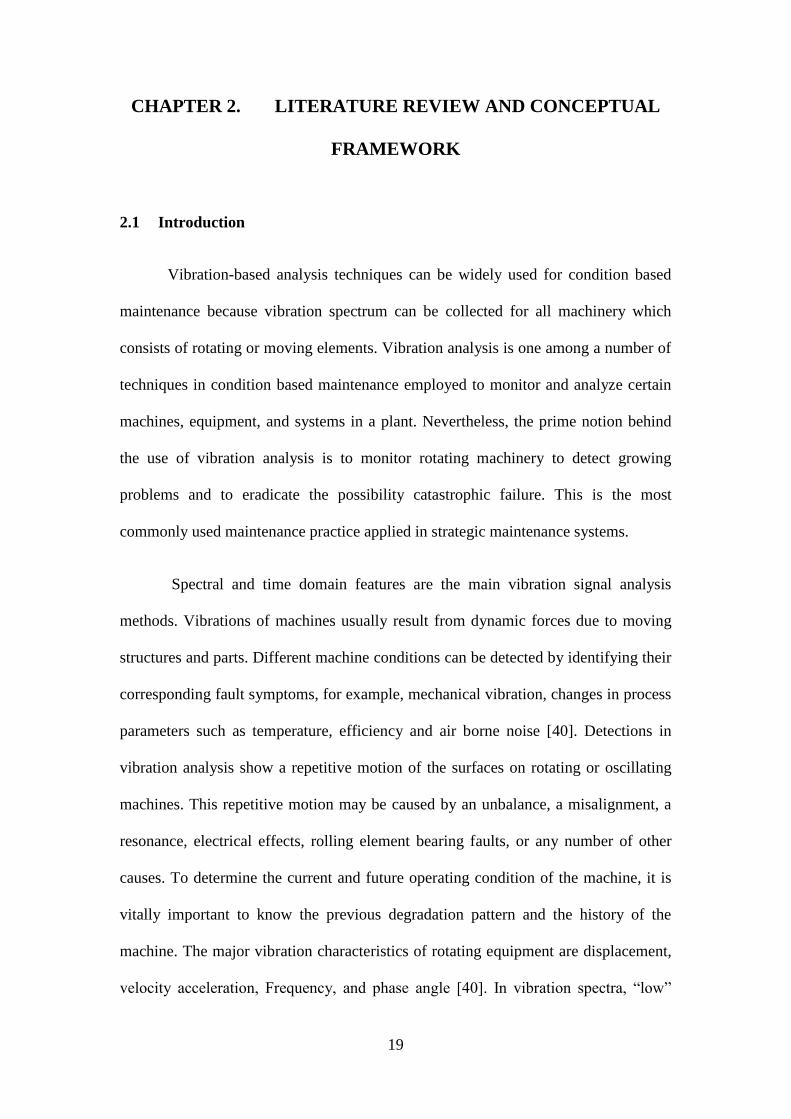
Vibration-based analysis techniques can be widely used for condition based
maintenance because vibration spectrum can be collected for all machinery which
consists of rotating or moving elements. Vibration analysis is one among a number of
techniques in condition based maintenance employed to monitor and analyze certain
machines, equipment, and systems in a plant. Nevertheless, the prime notion behind
the use of vibration analysis is to monitor rotating machinery to detect growing
problems and to eradicate the possibility catastrophic failure. This is the most
commonly used maintenance practice applied in strategic maintenance systems.
Spectral and time domain features are the main vibration signal analysis
methods. Vibrations of machines usually result from dynamic forces due to moving
structures and parts. Different machine conditions can be detected by identifying their
corresponding fault symptoms, for example, mechanical vibration, changes in process
parameters such as temperature, efficiency and air borne noise [40]. Detections in
vibration analysis show a repetitive motion of the surfaces on rotating or oscillating
machines. This repetitive motion may be caused by an unbalance, a misalignment, a
resonance, electrical effects, rolling element bearing faults, or any number of other
causes. To determine the current and future operating condition of the machine, it is
vitally important to know the previous degradation pattern and the history of the
machine. The major vibration characteristics of rotating equipment are displacement,
velocity acceleration, Frequency, and phase angle [40]. In vibration spectra, “low”

20
and “high” frequency ranges can be observed. The various types of vibration
frequencies in a rotating machine are directly related to the geometry and the
operating speed of the machine. By knowing the relationship between the frequencies
and the type of defect, vibration analysts can define the cause and severity of faults or
problem conditions. The low vibration range contains component frequencies
produced by rotational motion (harmonics). While the high vibration range contains
component frequencies resulting from the interaction between fluid-flow system and
medium flow. In a power steam turbine, blade frequency range (the latter case above)
is typically from a few hundred hertz to about 10–20 kHz, depending on the turbine
design [40]
The 3500 System provides continuous, online monitoring suitable for
machinery protection applications, and is designed to fully meet the requirements of
the American Petroleum Institute’s API 670 standard for such systems. Due to
stringent requirement in Oil and Gas industry especially in LNG, API standard is
mandatory in term of Safety requirement.
Notably, this chapter serves to reinforce the adopted approach for research by
identifying the existential gaps in the previous researches hence providing a fact-led
architectural platform that was used to build on the study.
2.2 Conceptual framework for the research study
From the conceptual framework of this research study, it is seen that recent
advancements within vibration monitoring and data analysis leads to the System 1
Condition monitoring software, which can accurately detect the problem before
machine failure. It will reduce the number of shutdowns of costly machinery and
maximize the production output in business operations of the any gas plant [13]. This
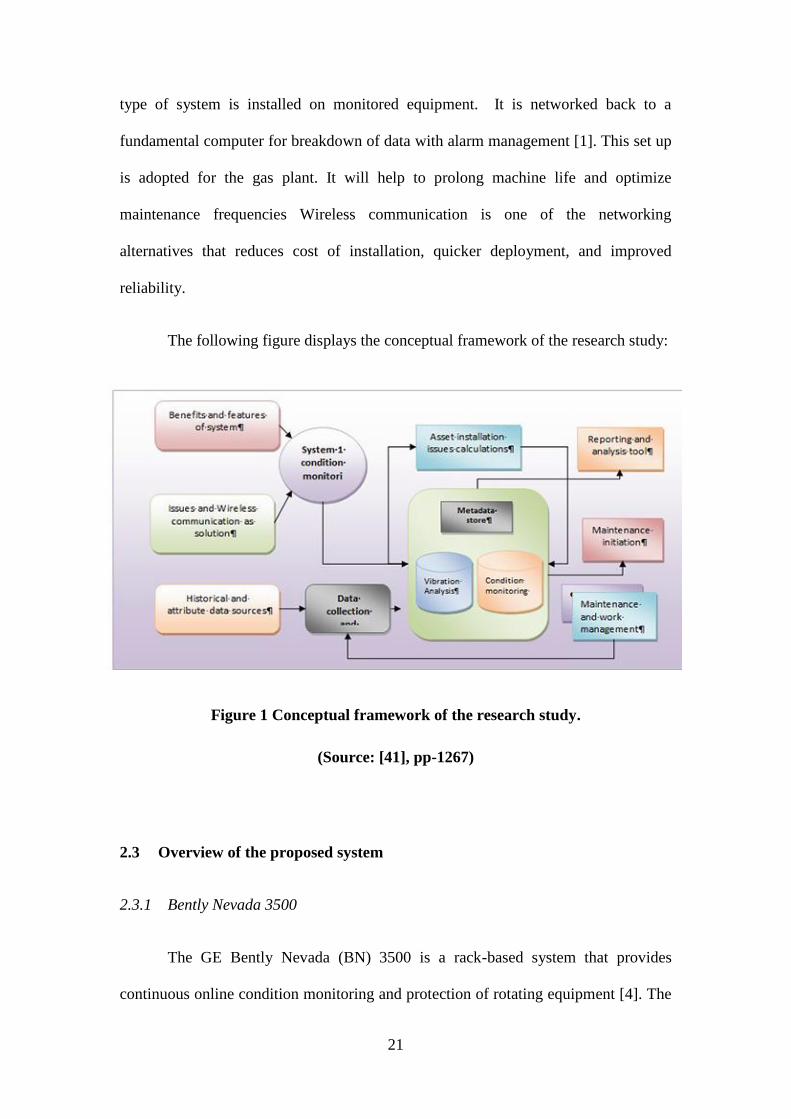
21
type of system is installed on monitored equipment. It is networked back to a
fundamental computer for breakdown of data with alarm management [1]. This set up
is adopted for the gas plant. It will help to prolong machine life and optimize
maintenance frequencies Wireless communication is one of the networking
alternatives that reduces cost of installation, quicker deployment, and improved
reliability.
The following figure displays the conceptual framework of the research study:
Figure 1 Conceptual framework of the research study.
(Source: [41], pp-1267)
2.3 Overview of the proposed system
2.3.1 Bently Nevada 3500
The GE Bently Nevada (BN) 3500 is a rack-based system that provides
continuous online condition monitoring and protection of rotating equipment [4]. The
22
system is highly modular, enabling customized functionality and integration with the
gas plant equipment. Specifically, a BN unit can be configured with any combination
of purpose-designed monitors, which plug into the rack’s backplane, to record
parameters such as radial and seismic vibration, eccentricity and differential
expansion. Each module consists of a main module and an I/O module, which installs
at the rear of the rack. The BN modules accept analogue signals from transducers
mounted on the monitored equipment [24]. These signals are carried to their
respective sensor units (which typically reside in a junction box near the monitored
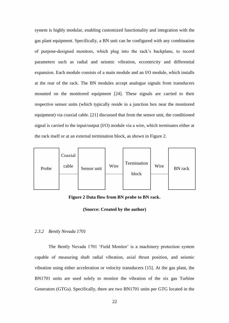
equipment) via coaxial cable. [21] discussed that from the sensor unit, the conditioned
signal is carried to the input/output (I/O) module via a wire, which terminates either at
the rack itself or at an external termination block, as shown in Figure 2.
Probe
Coaxial
cable Sensor unit
Wire Termination
block
Wire BN rack
Figure 2 Data flow from BN probe to BN rack.
(Source: Created by the author)
2.3.2 Bently Nevada 1701
The Bently Nevada 1701 ‘Field Monitor’ is a machinery protection system
capable of measuring shaft radial vibration, axial thrust position, and seismic
vibration using either acceleration or velocity transducers [15]. At the gas plant, the
BN1701 units are used solely to monitor the vibration of the six gas Turbine
Generators (GTGs). Specifically, there are two BN1701 units per GTG located in the
23
main substations. BN1701 units are much lower profile than BN3500 racks, and can
be skid mounted or mounted on a DIN rail within a cabinet. The 1701 system consists
of a terminal base where monitor cards and peripherals are mounted. The base
accommodates a single power supply, 4 dual-channel vibration monitors (each having
an associated transducer I/O module), one Keyphasor input module, one 1701/22
Management Interface Module, and I/O terminations for up to 9 externally-wired
transducers [17].
2.3.3 System 1 condition monitoring system in gas plant
While standalone BN3500 and BN1701 systems provide continuous automatic
shutdown protection of monitored assets, they do not provide any visibility of data for
diagnostic or trending evaluation. According to [32], for this reason, the BN systems
also serve as a gateway to the GE’s System 1 software platform. System 1 is GE
Energy’s original software stage for the real-time optimisation of machinery,
condition monitoring, and event diagnostics. It enables a predictive maintenance
strategy by linking portable data collection instruments and permanent monitoring by
BN3500 and BN1701 systems in an integrated condition monitoring environment [7].
The 3500/22M and 1701/22 data interface modules provide Ethernet ports for
connecting the BN3500 and BN1701 systems to a server computer running System 1
software over a LAN.
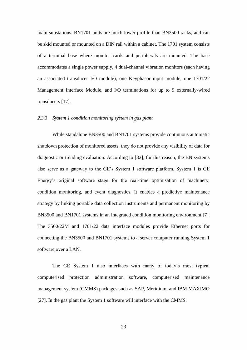
The GE System 1 also interfaces with many of today’s most typical
computerised protection administration software, computerised maintenance
management system (CMMS) packages such as SAP, Meridium, and IBM MAXIMO
[27]. In the gas plant the System 1 software will interface with the CMMS.
24
Figure 3 Principal System 1 software components and data flow paths.
(Source: Created by the author)
[31] pointed that the System 1 platform also installs a set of utility
applications. One such application is the Transient Data Manager Initialisation utility,
which is used to configure the 3500/22M and 1701/22 communications modules.
Configur
ation
Database
Historical
Database
BN
Data
Interfac
e
Data
Acquisition
Software
SQL Server
Software
Configuration
Software
Histor
ical
data
Live data Display
Software System 1 Platform
25
Using this utility, IP addresses, Keyphasor transducer parameters, and other operating
conditions are established. There are two major System 1 distributions on offer from
GE [23]. System 1 Classic, which is the platform that GE has implemented for their
refrigerant compressors, is the legacy version, and will ultimately be discontinued by
GE in favour of System 1 Evolution. For the purpose of this scoping project, System 1
Classic will be used.
[38] discussed that in the long term, it is the intention to use System 1
Evolution as the central platform for vibration data storage, analysis, and monitoring
at a gas plant. This platform will be integrated with Meridium and CMMS with the
verification and uploading of data performed by qualified personnel. System 1
Evolution is offered in two packages; fundamental and premium. The Fundamental
Package is the base level package designed to operate with supported portable
vibration analysers. The Premium Package integrates with both Portable Vibration
Analysers. GE, using a points system where points are calculated from the number of
equipment probes, issues system 1 Software licenses and associated costs.
[37] stated that the System 1 condition monitoring software represents Bently
Nevada leader online condition checking arrangement with integration to the business
driving line of online apparatus assurance and condition monitoring devices. Bently
Nevada gives adaptable arrangements ranging from delivery of product from
conveyance of item with flexible solutions with deployment services to finish
arrangement scope through supporting administration understanding. The System 1
software represents an approach to providing the clients with particular ecosystem for
plant-wide equipment administration. Using the System 1 condition monitoring
software provides the following advantages:
26
Capability: [34] stated that the premium package of System 1 condition
monitoring software is most beneficial in its aid for prioritization of work,
database management and diagnostics. It provides high-resolution trend,
alarm, and start up data. It reports the diagnostic data.
Accessibility: Flourishing condition monitoring programs require association
between departments and prescribed access to the tools. It has access to
remote transferable data transfer and user safety profiles.
Embedded expertise: The vibration monitoring is differentiated by giving
focused equipment explanations as well as best observe configuration [2].
[38] Investigated that all power-generating units consist of machinery that
causes vibration at the time of rotating the machines. It creates huge vibration in the
gas plant, which needs to be monitored. The machinery is monitored with an installed
condition monitoring system in order to conquer the vibration problems within the
machines. The most of the gas plants are monitoring their machinery on a cyclic basis
using the moveable data collector and a database program [27]. The monitoring
system consists of medium and large steam turbine generator, which is defined as
Turbine Supervisory Instrumentation (TSI) system [31]. It consists of radial
displacement vibration as well as axial position dimensions, which are connected with
the high speed of rotating machinery. Periodic monitoring provides an extremely cost-
efficient solution for the gas plants. It is due to a large number of positions to monitor
every month, usually 700 or 800. Still, some of the gas plants have moved their
measurement points on periodic monitoring to continuous monitoring [44]. This has
achieved a superior standard of maintenance, better machine operating condition and
personnel safety.
27
Hardware configuration
There are two practical approaches to facilitate a connection between the
Bently Nevada units and System 1 software, both having their own advantages and
disadvantages. These are:
Utilizing a VLAN configured over existing (already patched) optical fibres.
Configuring a dedicated BN condition monitoring LAN using spare optical
fibres.
The following sub-sections discuss the key hardware requirements for
implementing a dedicated BN condition monitoring network. In addition, LAN and
VLAN network architectures are proposed, including their hardware configuration
requirements and discussion of their relative pros and cons.
2.3.5 Network hardware requirements
Network switches
Network switch is a device that uses packet switching to send and receive data
between devices connected on a computer network at the data link layer (layer 2 of
the OSI model). Devices are uniquely identified by a MAC address. The make and
model of the network switch required to implement a condition monitoring network
depends on the network architecture (VLAN or LAN), location of the switch, and the
type of media that it must accept. Future expansion must also be considered when
designing a condition monitoring network. Indeed, projects to install Wi-Fi access
points in substations and connecting programmable logic controllers (PLCs) to the
CCA via are at varying stages of planning. For this reason, larger switches with spare
ports are preferred over smaller devices in locations.
28
The network switches in telecom racks within substation buildings are Cisco
Catalyst 3750-X rack-based managed switches. These devices can be configured with
a range of optical fibre and UTP port types and densities. The model found in CCA
and substation cabinets is the 3750-X-24PS switch, which offers 24V DC Power over
Ethernet (PoE) enabled ports, as well as a network module with four 10 Gigabit
Ethernet fibre optic ports . The 3750-X switches also support a number of Cisco’s
proprietary VLAN configuration protocols. All ports on existing 3750-X switches at
gas plant have been configured for VLANs by IS, and so cannot be configured for an
otherwise unmanaged LAN. Therefore, new and existing 3750-X switches can be
used in a condition monitoring VLAN.
A different approach is needed to implement a condition monitoring LAN. As
the BN units are located in non-standard equipment enclosures rather than 19 inch
racks, it makes practical sense to use DIN-mounted switches to permit shorter
cabling. Hirschmann RS20 series DIN-mount managed switches are used in Upstream
Operations (USO) to add connectivity to equipment packages, and have also been
used to facilitate fibre to copper conversion in the GE BN network on gas plant. Due
to their proven track record and for consistency with other areas of the business,
RS20s are a better option. Like the 3750-X switches, RS20’s are available in a range
of copper and fibre port densities. To sensibly construct a condition monitoring LAN,
certain locations also require network switches with > 2 optical fibre ports.
Rack and enclosure space
The network hardware in gas plant substation buildings is housed in APC
NetShelter SX equipment racks, which are industry standard 19-inch in width and 42
Rack Units (RU) in height. BN racks are either panel mounted or bulkhead mounted
29
in non-standard equipment enclosures containing other control and monitoring
hardware. If the DIN mounted switches and power supplies must be installed to
provide connectivity to a BN rack, they should be mounted as close as possible to the
unit (Marwala, 2012).
Power Supply
[31] reflected that a power supply unit (PSU) must accompany the installation
of any new network switch to supply and regulate the voltage required by the device.
For rack mounted equipment, Power Distribution Unit (PDU) rails are fitted in the
rear of all 42RU racks. They are rated to supply up to 10A at 230V, and accept a C14
input plug type, while outputs are C13 type receptacles [14]. DIN mounted network
switches demand a DIN mounted power supply. A range of these power supplies are
used across the gas plant, from suppliers such as Phoenix Contact and Traco Power
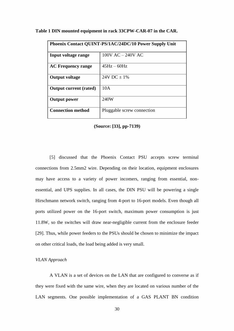
[33]. As shown in Table 1, Phoenix Contact QUINT-PS/1AC/24DC/10 have been
used for the existing GE BN network to power Hirschmann network switches, so it is
suggested that these also be used to supply DIN mounted switches in equipment
racks.
30
Table 1 DIN mounted equipment in rack 33CPW-CAR-07 in the CAR.
Phoenix Contact QUINT-PS/1AC/24DC/10 Power Supply Unit
Input voltage range 100V AC – 240V AC
AC Frequency range 45Hz – 60Hz
Output voltage 24V DC ± 1%
Output current (rated) 10A
Output power 240W
Connection method Pluggable screw connection
(Source: [33], pp-7139)
[5] discussed that the Phoenix Contact PSU accepts screw terminal
connections from 2.5mm2 wire. Depending on their location, equipment enclosures
may have access to a variety of power incomers, ranging from essential, non-
essential, and UPS supplies. In all cases, the DIN PSU will be powering a single
Hirschmann network switch, ranging from 4-port to 16-port models. Even though all
ports utilized power on the 16-port switch, maximum power consumption is just
11.8W, so the switches will draw near-negligible current from the enclosure feeder
[29]. Thus, while power feeders to the PSUs should be chosen to minimize the impact
on other critical loads, the load being added is very small.
VLAN Approach
A VLAN is a set of devices on the LAN that are configured to converse as if
they were fixed with the same wire, when they are located on various number of the
LAN segments. One possible implementation of a GAS PLANT BN condition
31
monitoring network is to configure a partitioned VLAN over the existing Ethernet and
optical fibre network. The condition monitoring VLAN will utilize dedicated ports on
existing and new network switches to connect BN units via a VLAN trunk to a switch
in the CCA telecom room. This VLAN configuration can be done remotely at a
software level by Information Services (IS), meaning the only spare optical fibres
required are those needed to connect to BN racks without network switches within
physical proximity (i.e. TIAC Buildings and Regeneration Gas Compressor
Packages).
For BN units in the Main Substations and Loading Substation, the physical
network connections needed to connect to System 1 servers via a VLAN. In general, a
new CAT5e Ethernet cable is needed to connect each BN rack to the nearest network
switch. In case of the GTGs, the BN1701 units in the main substations require a DB-9
to CAT5e Ethernet cable.
32
Existing Optical Fibre Link
New CAT5e Ethernet Cable
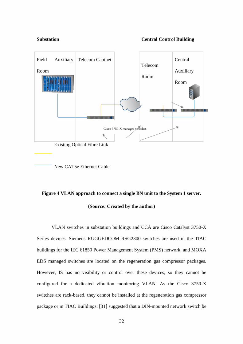
Figure 4 VLAN approach to connect a single BN unit to the System 1 server.
(Source: Created by the author)
VLAN switches in substation buildings and CCA are Cisco Catalyst 3750-X
Series devices. Siemens RUGGEDCOM RSG2300 switches are used in the TIAC
buildings for the IEC 61850 Power Management System (PMS) network, and MOXA
EDS managed switches are located on the regeneration gas compressor packages.
However, IS has no visibility or control over these devices, so they cannot be
configured for a dedicated vibration monitoring VLAN. As the Cisco 3750-X
switches are rack-based, they cannot be installed at the regeneration gas compressor
package or in TIAC Buildings. [31] suggested that a DIN-mounted network switch be
Substation Central Control Building
Field Auxiliary
Room
Telecom Cabinet
Telecom
Room
Central
Auxiliary
Room
Cisco 3750-X managed switches
System 1 Server
33
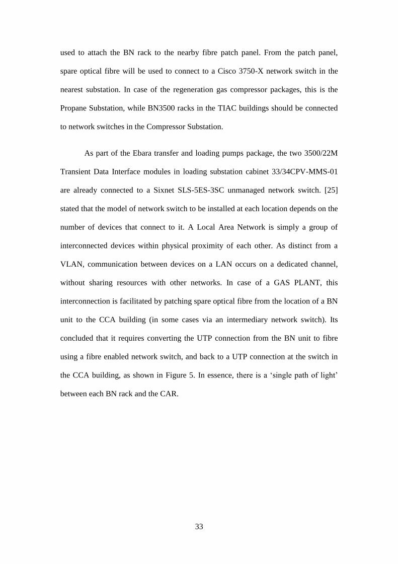
used to attach the BN rack to the nearby fibre patch panel. From the patch panel,
spare optical fibre will be used to connect to a Cisco 3750-X network switch in the
nearest substation. In case of the regeneration gas compressor packages, this is the
Propane Substation, while BN3500 racks in the TIAC buildings should be connected
to network switches in the Compressor Substation.
As part of the Ebara transfer and loading pumps package, the two 3500/22M
Transient Data Interface modules in loading substation cabinet 33/34CPV-MMS-01
are already connected to a Sixnet SLS-5ES-3SC unmanaged network switch. [25]
stated that the model of network switch to be installed at each location depends on the
number of devices that connect to it. A Local Area Network is simply a group of
interconnected devices within physical proximity of each other. As distinct from a
VLAN, communication between devices on a LAN occurs on a dedicated channel,
without sharing resources with other networks. In case of a GAS PLANT, this
interconnection is facilitated by patching spare optical fibre from the location of a BN
unit to the CCA building (in some cases via an intermediary network switch). Its
concluded that it requires converting the UTP connection from the BN unit to fibre
using a fibre enabled network switch, and back to a UTP connection at the switch in
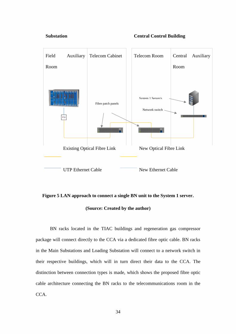
the CCA building, as shown in Figure 5. In essence, there is a ‘single path of light’
between each BN rack and the CAR.
34
Existing Optical Fibre Link New Optical Fibre Link
UTP Ethernet Cable
New Ethernet Cable
Figure 5 LAN approach to connect a single BN unit to the System 1 server.
(Source: Created by the author)
BN racks located in the TIAC buildings and regeneration gas compressor
package will connect directly to the CCA via a dedicated fibre optic cable. BN racks
in the Main Substations and Loading Substation will connect to a network switch in
their respective buildings, which will in turn direct their data to the CCA. The
distinction between connection types is made, which shows the proposed fibre optic
cable architecture connecting the BN racks to the telecommunications room in the
CCA.
Substation Central Control Building
Field Auxiliary
Room
Telecom Cabinet Telecom Room Central Auxiliary
Room
Fibre patch panels
Network switch
System 1 Server/s
35
2.3.7 Software Configuration
In addition to the investment in hardware, all BN units and System 1 servers
must be appropriately configured at the software level to facilitate interconnection
between the field and CAR. In general, the steps that must be taken to configure the
BN racks and System 1 software are well documented by GE. Useful documentation
includes:
3500 Monitoring System Installation Manual (Revision E)
System 1 Classic Installation Quick Start Guide (Revision NC)
BN3500 software configuration
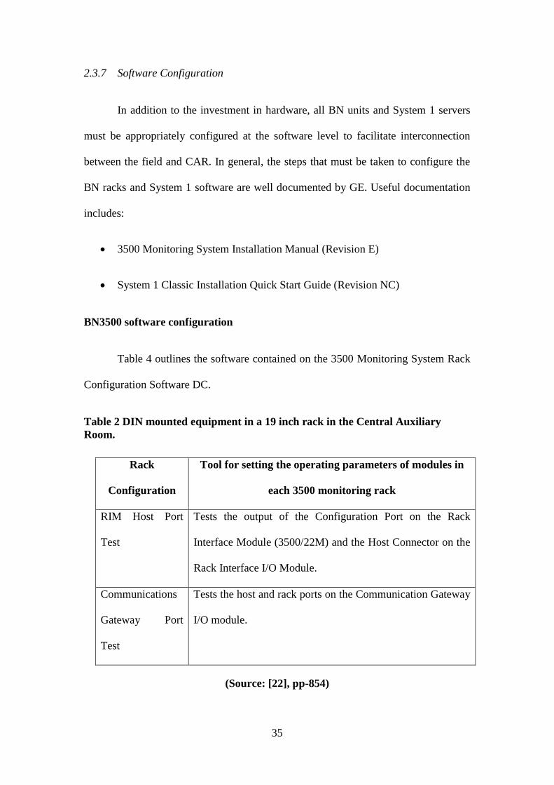
Table 4 outlines the software contained on the 3500 Monitoring System Rack
Configuration Software DC.
Table 2 DIN mounted equipment in a 19 inch rack in the Central Auxiliary
Room.
Rack
Configuration
Tool for setting the operating parameters of modules in
each 3500 monitoring rack
RIM Host Port
Test
Tests the output of the Configuration Port on the Rack
Interface Module (3500/22M) and the Host Connector on the
Rack Interface I/O Module.
Communications
Gateway Port
Test
Tests the host and rack ports on the Communication Gateway
I/O module.
(Source: [22], pp-854)
36
As all the BN racks on the gas plant are operational, their rack configurations,
alarm set points, and alarm drive logic for relay channels will already have been
configured. However, to enable a network interface to the BN racks via the 3500/22M
Transient Data Interface (TDI) module, the racks require additional configuration.
This will involve connecting a laptop computer directly to the TDI module’s
configuration port via an RS232 cable. After a rack is configured to communicate
over a LAN, subsequent re-configurations can be made remotely over the network
connection.
The process of configuring the 3500/22M TDI module is described in Section
3.3 of the 3500 Monitoring System Installation Manual. It permits the user to set up
the rack IP address and subnet mask; a rack network device name and a connection
password. Once a 3500 rack has a network connection to a DAQ Server and software,
it will be visible to configure via System 1 software [29].
2.3.8 BN1701 Software Configuration
System 1 Configuration
This section provides an outline of the System 1 setup process Within the
System 1 Configuration Software, each BN3500 and BN1701 Monitor Rack, monitor,
and channel must be configured in an Instrument Hierarchy. [37] stated that each
channel is linked to a sampler card in the 3500/22M or 1701/22 module. Once the
online monitors are configured in the Instrument Hierarchy, each channel is then
mapped to a measurement location in the Enterprise Hierarchy [28]. Measurement
locations must then be mapped to a corresponding hardware device, so that the
System 1 software knows where to find the data for that point. Online monitoring of
machinery data requires the System 1 Data Acquisition software to be active 24/7.
37
Due to the complexity and scale of the System 1 platform, specialist GE technicians
should be engaged to install and configure the System 1 software and servers.
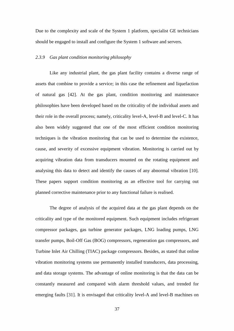
2.3.9 Gas plant condition monitoring philosophy
Like any industrial plant, the gas plant facility contains a diverse range of
assets that combine to provide a service; in this case the refinement and liquefaction
of natural gas [42]. At the gas plant, condition monitoring and maintenance
philosophies have been developed based on the criticality of the individual assets and
their role in the overall process; namely, criticality level-A, level-B and level-C. It has
also been widely suggested that one of the most efficient condition monitoring
techniques is the vibration monitoring that can be used to determine the existence,
cause, and severity of excessive equipment vibration. Monitoring is carried out by
acquiring vibration data from transducers mounted on the rotating equipment and
analysing this data to detect and identify the causes of any abnormal vibration [10].
These papers support condition monitoring as an effective tool for carrying out
planned corrective maintenance prior to any functional failure is realised.
The degree of analysis of the acquired data at the gas plant depends on the
criticality and type of the monitored equipment. Such equipment includes refrigerant
compressor packages, gas turbine generator packages, LNG loading pumps, LNG
transfer pumps, Boil-Off Gas (BOG) compressors, regeneration gas compressors, and
Turbine Inlet Air Chilling (TIAC) package compressors. Besides, as stated that online
vibration monitoring systems use permanently installed transducers, data processing,
and data storage systems. The advantage of online monitoring is that the data can be
constantly measured and compared with alarm threshold values, and trended for
emerging faults [31]. It is envisaged that criticality level-A and level-B machines on
38
the gas plant will be continuously monitored for vibration data using an ‘online’
condition monitoring system.
All offline monitoring system requires manual collection of data on a periodic
basis. An offline system consists of a portable vibration data collector/analyzer and a
central data processing and storage system. Offline data collection is used for all
equipment other than criticality level-A. In the gas plant GE refrigerant compressor
packages (including turbines, gearboxes, and compressors) are criticality level-A. All
criticality level-B equipment will also be monitored online. All lower criticality
equipment will be on run-to-failure or proactive maintenance strategies to optimise
maintenance costs.
2.3.10 Existing Systems
Condition monitoring procedure
The current procedure for the collection of vibration data involves manual data
logging with BN SCOUT portable vibration analysers. The work orders (WOs) for the
scheduled data collections are generated by Oracle eAM (GAS PLANT’s CMMS),
and clearly define the measurement points and vibration parameters to be collected.
The vibration measurements will be taken by an externally-contracted vibration
technician. After the collection process, the measurements will be uploaded to the
System 1 Evolution software (which has native support for BN SCOUT portables) for
analysis and exception reporting.
39
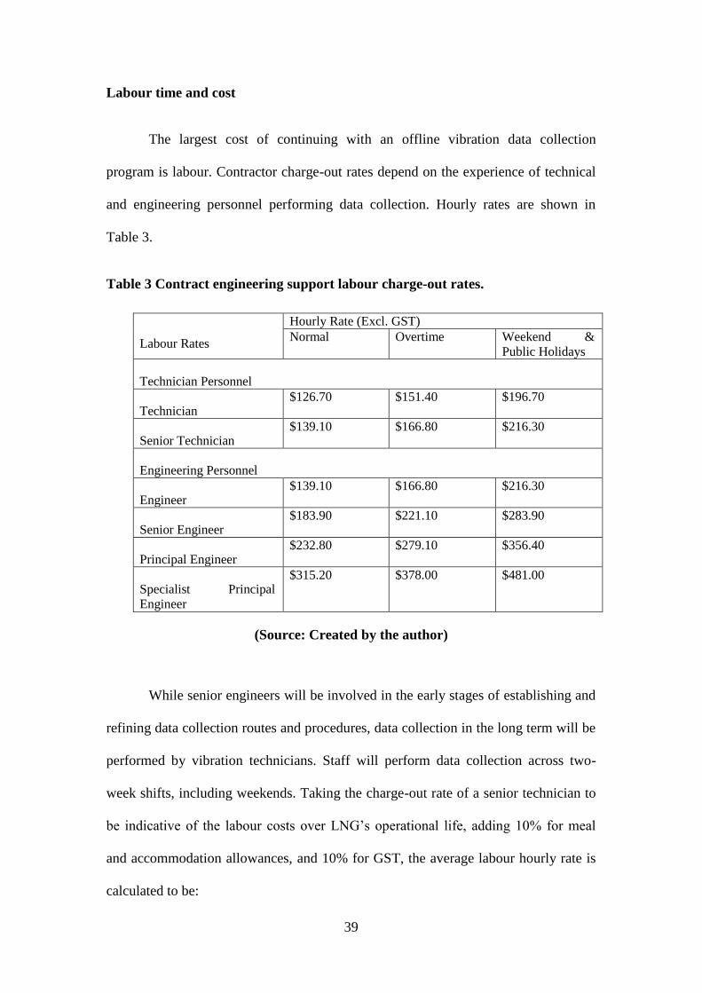
Labour time and cost
The largest cost of continuing with an offline vibration data collection
program is labour. Contractor charge-out rates depend on the experience of technical
and engineering personnel performing data collection. Hourly rates are shown in
Table 3.
Table 3 Contract engineering support labour charge-out rates.
Labour Rates
Hourly Rate (Excl. GST)
Normal Overtime Weekend &
Public Holidays
Technician Personnel
Technician $126.70 $151.40 $196.70
Senior Technician $139.10 $166.80 $216.30
Engineering Personnel
Engineer $139.10 $166.80 $216.30
Senior Engineer $183.90 $221.10 $283.90
Principal Engineer $232.80 $279.10 $356.40
Specialist Principal
Engineer
$315.20 $378.00 $481.00
(Source: Created by the author)
While senior engineers will be involved in the early stages of establishing and
refining data collection routes and procedures, data collection in the long term will be
performed by vibration technicians. Staff will perform data collection across two-
week shifts, including weekends. Taking the charge-out rate of a senior technician to
be indicative of the labour costs over LNG’s operational life, adding 10% for meal
and accommodation allowances, and 10% for GST, the average labour hourly rate is
calculated to be:
40
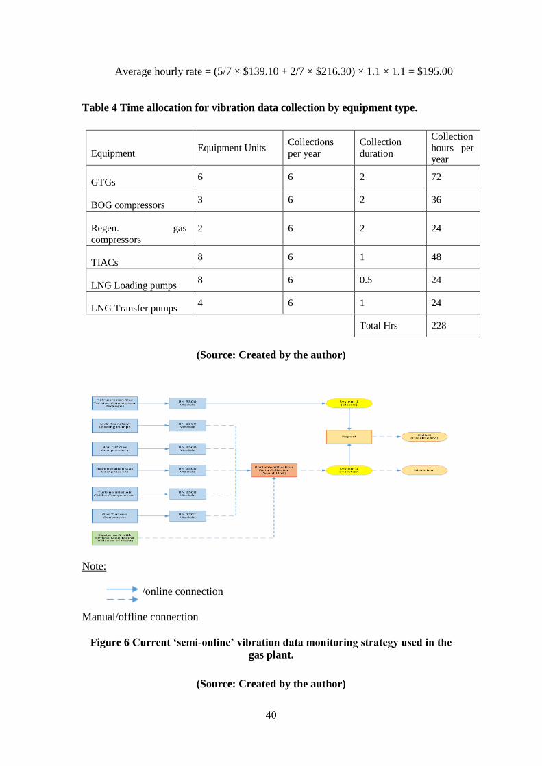
Average hourly rate = (5/7 × $139.10 + 2/7 × $216.30) × 1.1 × 1.1 = $195.00
Table 4 Time allocation for vibration data collection by equipment type.
Equipment Equipment Units
Collections
per year
Collection
duration
Collection
hours per
year
GTGs 6 6 2 72
BOG compressors 3 6 2 36
Regen. gas
compressors 2 6 2 24
TIACs 8 6 1 48
LNG Loading pumps 8 6 0.5 24
LNG Transfer pumps 4 6 1 24
Total Hrs 228
(Source: Created by the author)
Note:
Direct/online connection
Manual/offline connection
Figure 6 Current ‘semi-online’ vibration data monitoring strategy used in the
gas plant.
(Source: Created by the author)
41
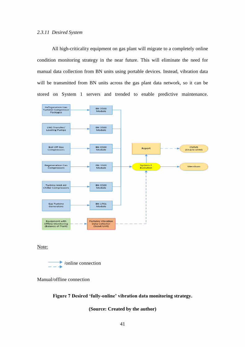
2.3.11 Desired System
All high-criticality equipment on gas plant will migrate to a completely online
condition monitoring strategy in the near future. This will eliminate the need for
manual data collection from BN units using portable devices. Instead, vibration data
will be transmitted from BN units across the gas plant data network, so it can be
stored on System 1 servers and trended to enable predictive maintenance.
Note:
Direct/online connection
Manual/offline connection
Figure 7 Desired ‘fully-online’ vibration data monitoring strategy.
(Source: Created by the author)
42
2.4 Features of the System 1 condition monitoring software
System 1 condition monitoring is implemented within the gas plant for low-
speed machines as they are large and it consists of high rotating inertia. In most of the
low-speed machines, bearings are the critical component, which are required to be
monitored. [30] researched on identifying the rolling element bearing which faults by
means of the vibration analysis. When the machine is at a slow speed, the impact
energy between the rotating parts and defects is low. It is identified through the use of
vibration transducer.
Sophisticated alarm management: System 1 allows management by
exemption with alarm handling abilities for the gas plant. It ensures that at the time of
any issue and problems the alarm will ring.
Analytic and diagnostic capabilities: The data is manipulated using library
tools and functions. The data is analysed in the spreadsheets. Advanced plot
management tool like plot grouping are used to generate, duplicate, keep, and
access plots of ordinary interest.
Resolution of storage: The data is stored and captured in a configurable for
each point. It is stated that when machinery is monitored, there is a high risk
data theft and access to data by any third party users [19]. Therefore, it will
securely give resolution to storage of monitored data.
Customizable display: [16] stated that the users of System 1 can configure the
display capabilities and ensure that the assets and portions are relevant as
presented.
Support for Virtual private network technologies: The corporate network
accesses most of the VPN technologies without affecting the security of the
data. The System 1 condition monitoring should support technology and
provide remote access capabilities.
43
2.5 Improvement in safety issues by using System 1 condition monitoring
system
Condition monitoring (CM) is referred to monitoring key parameters as well
as indicators of equipment condition in the gas plant. It is used to analyse health of the
machinery to make improvement in the safety issues. Jung and Bae (2015)
investigated that due to the implementation of this system in a gas plant, the
machinery stops safely and prevents the machinery from stopping abruptly.
Therefore, fatal accidents and injuries are reduced that are caused by the machinery.
CM system is used manually by different diagnostic checks such as levels and kinds
of dissolved gases, checking of gas pressure and timing and operating checks of the
machinery. [36] Suggested that use of online monitoring system is achieved with the
use of sensors and devices. This online system is more advanced and, therefore, it is
continuously grown as new ones in the developed market.
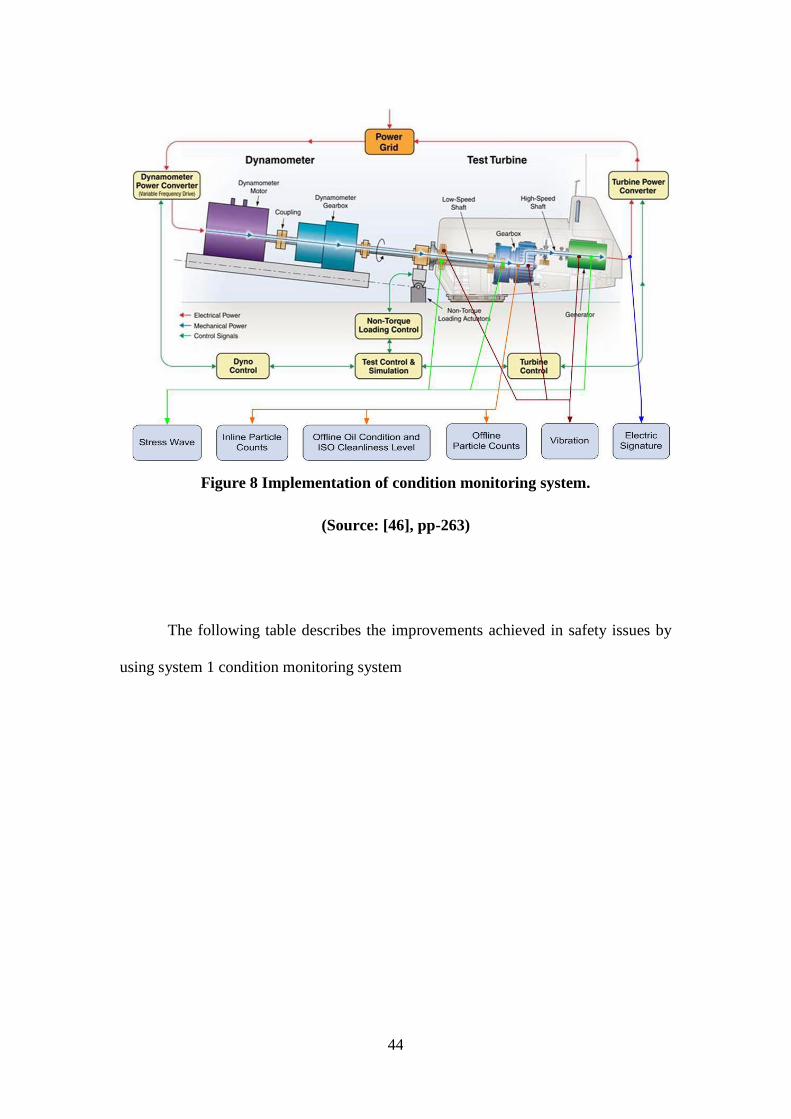
[30] reflected on some of the experiences, which are gained due to the use of
online, monitoring devices are gas in the monitoring of oil, monitoring of temperature
and moisture of the gas plant. According to [32], the online monitoring is continuous,
and it picks up vital issues before traditional diagnostics, and it is used to attain
business benefits within gas plant. The condition monitoring system is implemented
using integrated approach by working with commercial equipment suppliers [11]. An
integrated approach is used to provide reliable as well as comprehensive solutions
required by the industry. [20] investigated that there are four condition monitoring
techniques such as vibration, offline analysis of oil sample, acoustic emission, and
offline real time lubricant condition monitoring.
44
Figure 8 Implementation of condition monitoring system.
(Source: [46], pp-263)
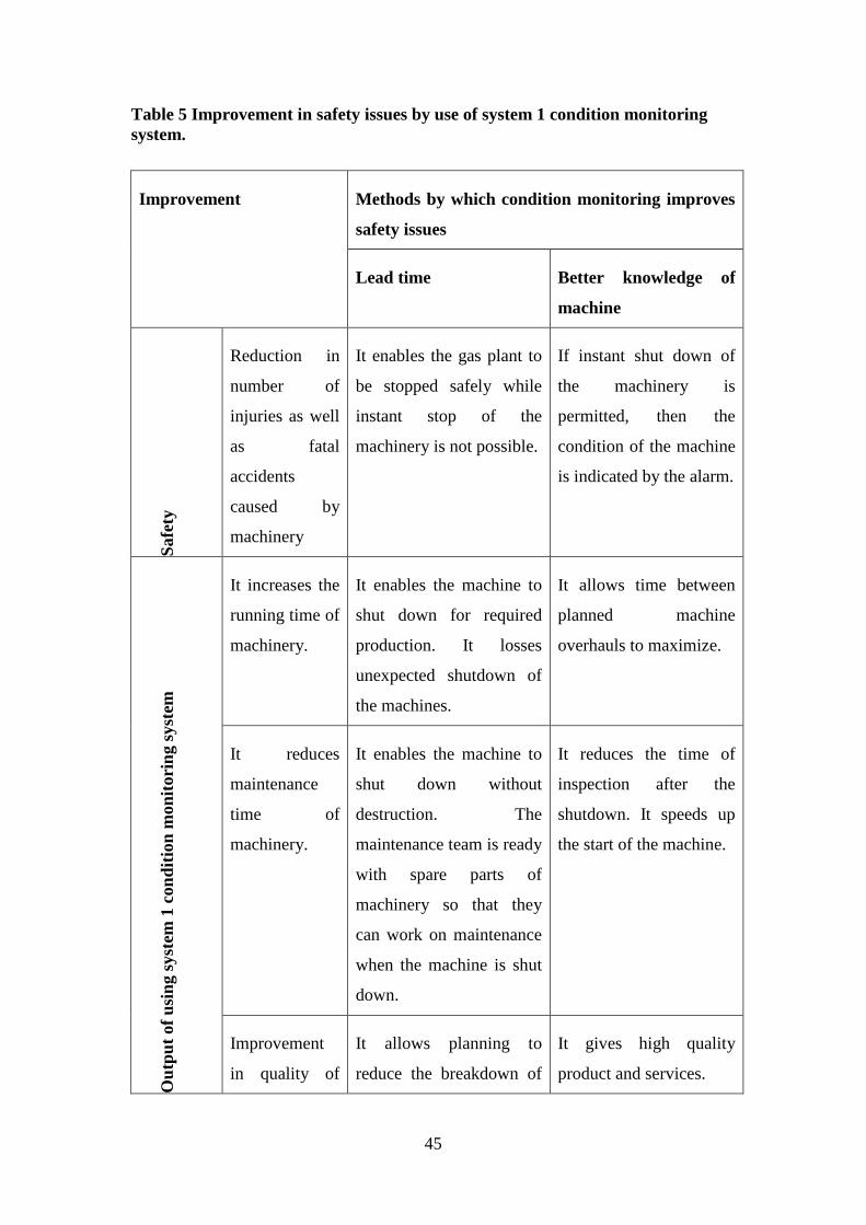
The following table describes the improvements achieved in safety issues by
using system 1 condition monitoring system
45
Table 5 Improvement in safety issues by use of system 1 condition monitoring
system.
Improvement Methods by which condition monitoring improves
safety issues
Lead time Better knowledge of
machine
Safe
ty
Reduction in
number of
injuries as well
as fatal
accidents
caused by
machinery
It enables the gas plant to
be stopped safely while
instant stop of the
machinery is not possible.
If instant shut down of
the machinery is
permitted, then the
condition of the machine
is indicated by the alarm.
Ou
tpu
t of
usi
ng s
yst
em 1
con
dit
ion
mon
itori
ng s
yst
em
It increases the
running time of
machinery.
It enables the machine to
shut down for required
production. It losses
unexpected shutdown of
the machines.
It allows time between
planned machine
overhauls to maximize.
It reduces
maintenance
time of
machinery.
It enables the machine to
shut down without
destruction. The
maintenance team is ready
with spare parts of
machinery so that they
can work on maintenance
when the machine is shut
down.
It reduces the time of
inspection after the
shutdown. It speeds up
the start of the machine.
Improvement
in quality of
It allows planning to
reduce the breakdown of
It gives high quality
product and services.

46
products machinery. It also reduces
the time to work on
customer's complaints,
and it enhances the
reputation of the
company.
(Source: Created by the author)
2.6 Improvements in production loss and maintenance issues by using System
1 condition monitoring system
The online condition monitoring systems are particularly helpful in the heavy
industry where 24 hr production is maintained.
Result of frequent mechanical failures across the paper mill, Alma Paper Mill,
Quebec, Canada conducted bearing seize and bearing fault case study. An effective
solution to a mill's maintenance problems is to operate a programme where the
condition of the machines is measured, and maintenance is carried out based on these
measurements [47]. Vibration monitoring of rotating machinery is considered as the
best method of determining a machine's condition. This allows repair to be carried out
only when the measurements indicate that the condition of the machine is
deteriorating, and maintenance to be scheduled well ahead of time [47]. In this way
unexpected breakdowns are avoided and machine running time is maximized. Based
on the case study recommendation, the paper mill management decided to install an
online condition monitoring system in the mill.
47
2.7 Summary
The proposed system is used manually by different diagnostic checks such as
stages, sorts of dissolved gases, examination of gas pressure, and time and in-service
checks of the equipment. The vibration analysis leads to modern condition monitoring
systems, which can progress the production of a gas plant.
Online condition monitoring also enables truly planned maintenance, meaning
maintenance resources can be allocated more efficiently. For instance, servicing and
part replacement can be scheduled in advance to minimise disruption to production
and other parts of the operation. As a consequence, there are obvious and immediate
efficiency improvements that come with migrating vibration monitoring to an online
system plus huge cost savings.
High site occupancy rate will be reduced by the proposed online data
collection. The amount of time taken to collect data from BN racks for the various
equipment types is estimated as too high.
The online vibration monitoring system at the Alma Paper Mill, Quebec,
Canada has shown itself to be a resounding success story. There have been no
expected breakdowns on the monitored equipment since installation of the system. All
problems have been detected by the system early enough to enable repair to be
scheduled for a planned maintenance [47]. This record means that initial investment
for the system and training has paid back.
48
CHAPTER 3. RESEARCH METHODOLOGY
3.1 Introduction
The research methodology chapter articulates the reasons for choosing a
particular data collection procedure and technique for the survey. The chosen methods
are appropriate to fulfil the aims of the research study. Use of the research philosophy
helps in comprehending the strategy adopted in investigating the connection of the
Bently Nevada vibration racks to the GE System 1 condition monitoring software.
[12] pointed out that following a research methodology also limits some errors. In
addition, the specialist has tried to be relevant at every step of the process of
examination that can assist in an improved study of the benefits of connecting the
Bently Nevada vibration racks to the GE System 1 condition monitoring software.
3.2 Research philosophy
The research philosophy is adopting important assumptions based on the
selected research topic. [35] pointed that assumptions are required to conduct a
research study for achieving a successful outcome. In part, the philosophy which is
adopted, will be influenced by practical considerations. The critical thinking process
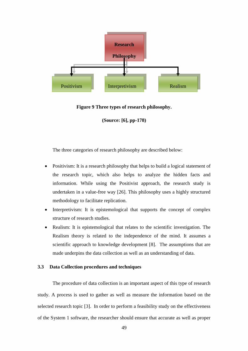
is required to evaluate the selected research topic [5]. There are three categories of
research philosophy: Positivism, Interpretivism, and Realism, as shown in the Figure
9.
49
Figure 9 Three types of research philosophy.
(Source: [6], pp-178)
The three categories of research philosophy are described below:
Positivism: It is a research philosophy that helps to build a logical statement of
the research topic, which also helps to analyze the hidden facts and
information. While using the Positivist approach, the research study is
undertaken in a value-free way [26]. This philosophy uses a highly structured
methodology to facilitate replication.
Interpretivism: It is epistemological that supports the concept of complex
structure of research studies.
Realism: It is epistemological that relates to the scientific investigation. The
Realism theory is related to the independence of the mind. It assumes a
scientific approach to knowledge development [8]. The assumptions that are
made underpins the data collection as well as an understanding of data.
3.3 Data Collection procedures and techniques
The procedure of data collection is an important aspect of this type of research
study. A process is used to gather as well as measure the information based on the
selected research topic [3]. In order to perform a feasibility study on the effectiveness
of the System 1 software, the researcher should ensure that accurate as well as proper
Research
Philosophy
Positivism Interpretivism Realism
50
data collection methods are selected [9]. Selection of proper data collection method
reduces the occurrence of errors. Also, accurate data ensures that the collected data is
highly acceptable for the research.
3.3.1 Data sources
In this research study, two categories of data sources are used: primary and
secondary. Primary data sources provide original information on which the research
study is based. The source of primary data is a population sample [28]. The first step
in the research process is to determine the target population. The sources of primary
data collection procedures are survey, interview, and focus group. Secondary data
sources provide the analysis of primary sources. It is used to support this particular
thesis to persuade the audiences to accept a certain point of view.
3.4 Sample and population
In the present study, the employees and managers form the population group.
The sample of employees is simply a random probability sampling, where no other
criterion to select is used. With the use of an online survey questionnaire, the
employees are asked to participate in the survey. The questionnaire is based on the
satisfaction and dissatisfaction level of employees. To conduct the study, a sample
size of 100 employees is considered.
51
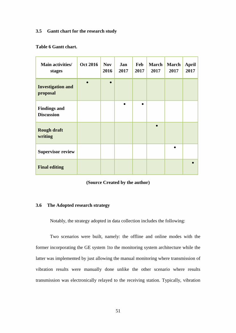
3.5 Gantt chart for the research study
Table 6 Gantt chart.
Main activities/
stages
Oct 2016 Nov
2016
Jan
2017
Feb
2017
March
2017
March
2017
April
2017
Investigation and
proposal
Findings and
Discussion
Rough draft
writing
Supervisor review
Final editing
(Source Created by the author)
3.6 The Adopted research strategy
Notably, the strategy adopted in data collection includes the following:
Two scenarios were built, namely: the offline and online modes with the
former incorporating the GE system 1to the monitoring system architecture while the
latter was implemented by just allowing the manual monitoring where transmission of
vibration results were manually done unlike the other scenario where results
transmission was electronically relayed to the receiving station. Typically, vibration
52
measurements were done for a full shift per day for a period of 4 months and
vibrational trends were monitored as well.
Parameters such as cost of unplanned breakdowns were monitored in a
systematic fashion where the operators directly involved in the section under question
would make an occurrence note and one of the data collection assistants would
prepare a bimonthly report detailing the relevant parameters such as: root cause,
duration, monetary effects, safety and production bottlenecks experienced in the cause
of plant performance. To narrow the scope of study, a section of the gas plant facility,
namely the compressor section was identified as the research location.
The expert, operators and technicians opinion were also taken into account. It
was important to get the worker opinion on the likely changes in the monitoring
system should it prove a success. Notably, questionnaires were designed to help
capture first hand perception, acceptability and attitude of the workers. It should be
noted that the rationale of seeking the expert opinion on the said subject was chiefly
to gain the experiential and informational resources critical to the analysis and
presentation of a more fact-backed research findings. This was done by organizing
coordinated interviews spread across the entire 4-month period.
Secondary sources such as journals and books by different authors were
perused with the intention to uncover the emerging concepts such as online vibration
monitoring modes. Additionally, the secondary sources revealed a near perfect
systems monitoring architectural platforms that have been implemented in related
industries in different companies.
53
CHAPTER 4. FINDINGS AND DISCUSSION
4.1 Introduction
In the Findings and Discussion chapter, the researcher analyzes the collected
data, which is gathered from the employees and managers working in the gas plant.
With the help of the quantitative analysis, the data is analyzed to investigate the
selected topic and increase the quality of information. This data analysis helps the
research analyst to implement theoretical knowledge within the practical application.
However, the data analysis might also involve some limitations and data
manipulation. The role of the employees and managers is evaluated in this particular
chapter by using the feedback given by the participants of the gas plant. Based on the
analyzed data, the research analyst gained information for analyzing the findings.
4.2 Data analysis and findings
In this research study, the employees are asked to answer an online
questionnaire survey to help the research analyst in identifying the effectiveness of
the Bently Nevada to System 1 condition monitoring system. The total sample size for
this research study is 100. The primary data source and quantitative data technique is
used for collecting data.
Quantitative analysis- feasibility study on the effectiveness of proposed system
How long have you been working in the gas plant?
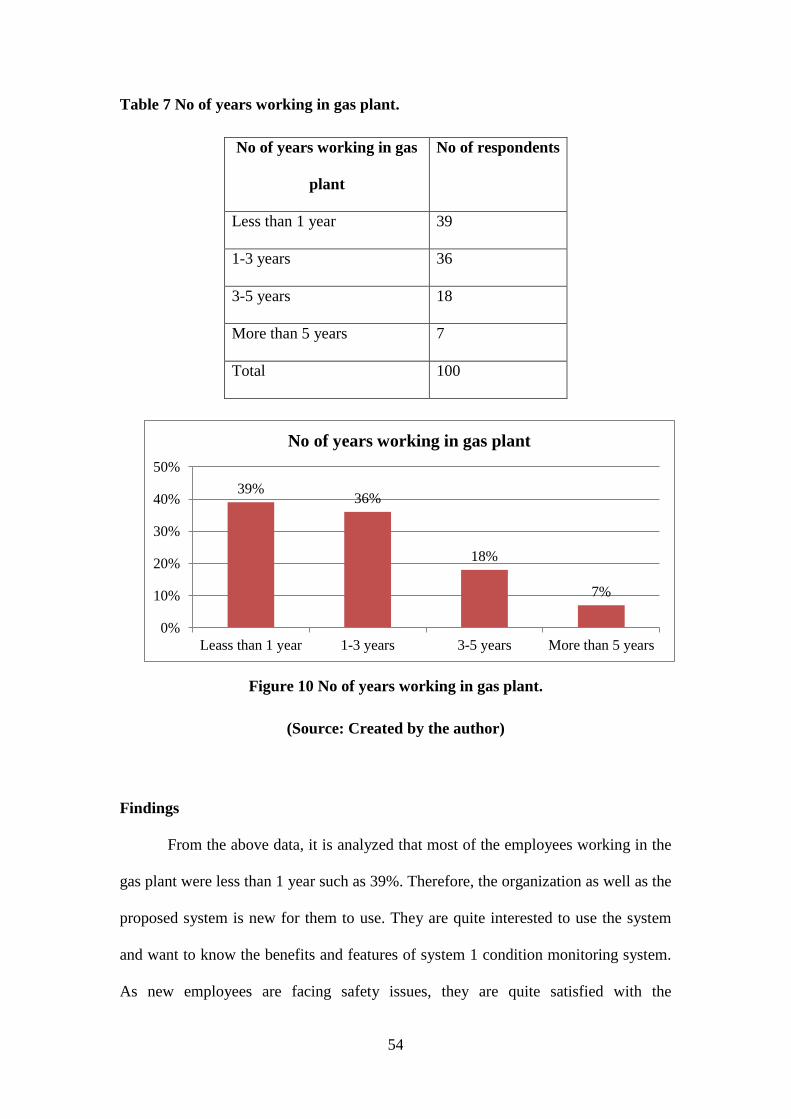
54
Table 7 No of years working in gas plant.
No of years working in gas
plant
No of respondents
Less than 1 year 39
1-3 years 36
3-5 years 18
More than 5 years 7
Total 100
Figure 10 No of years working in gas plant.
(Source: Created by the author)
Findings
From the above data, it is analyzed that most of the employees working in the
gas plant were less than 1 year such as 39%. Therefore, the organization as well as the
proposed system is new for them to use. They are quite interested to use the system
and want to know the benefits and features of system 1 condition monitoring system.
As new employees are facing safety issues, they are quite satisfied with the
39% 36%
18%
7%
0%
10%
20%
30%
40%
50%
Leass than 1 year 1-3 years 3-5 years More than 5 years
No of years working in gas plant
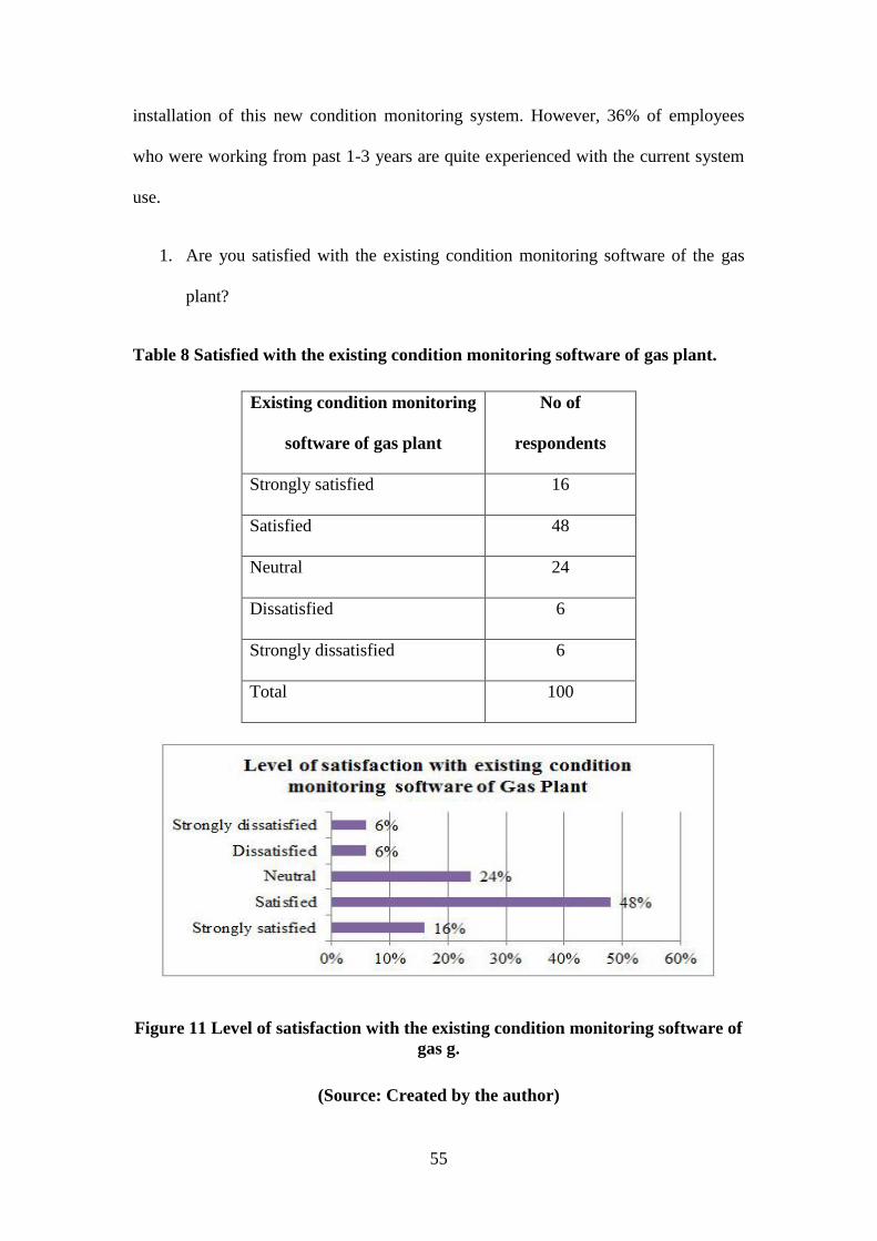
55
installation of this new condition monitoring system. However, 36% of employees
who were working from past 1-3 years are quite experienced with the current system
use.
1. Are you satisfied with the existing condition monitoring software of the gas
plant?
Table 8 Satisfied with the existing condition monitoring software of gas plant.
Existing condition monitoring
software of gas plant
No of
respondents
Strongly satisfied 16
Satisfied 48
Neutral 24
Dissatisfied 6
Strongly dissatisfied 6
Total 100
Figure 11 Level of satisfaction with the existing condition monitoring software of
gas g.
(Source: Created by the author)
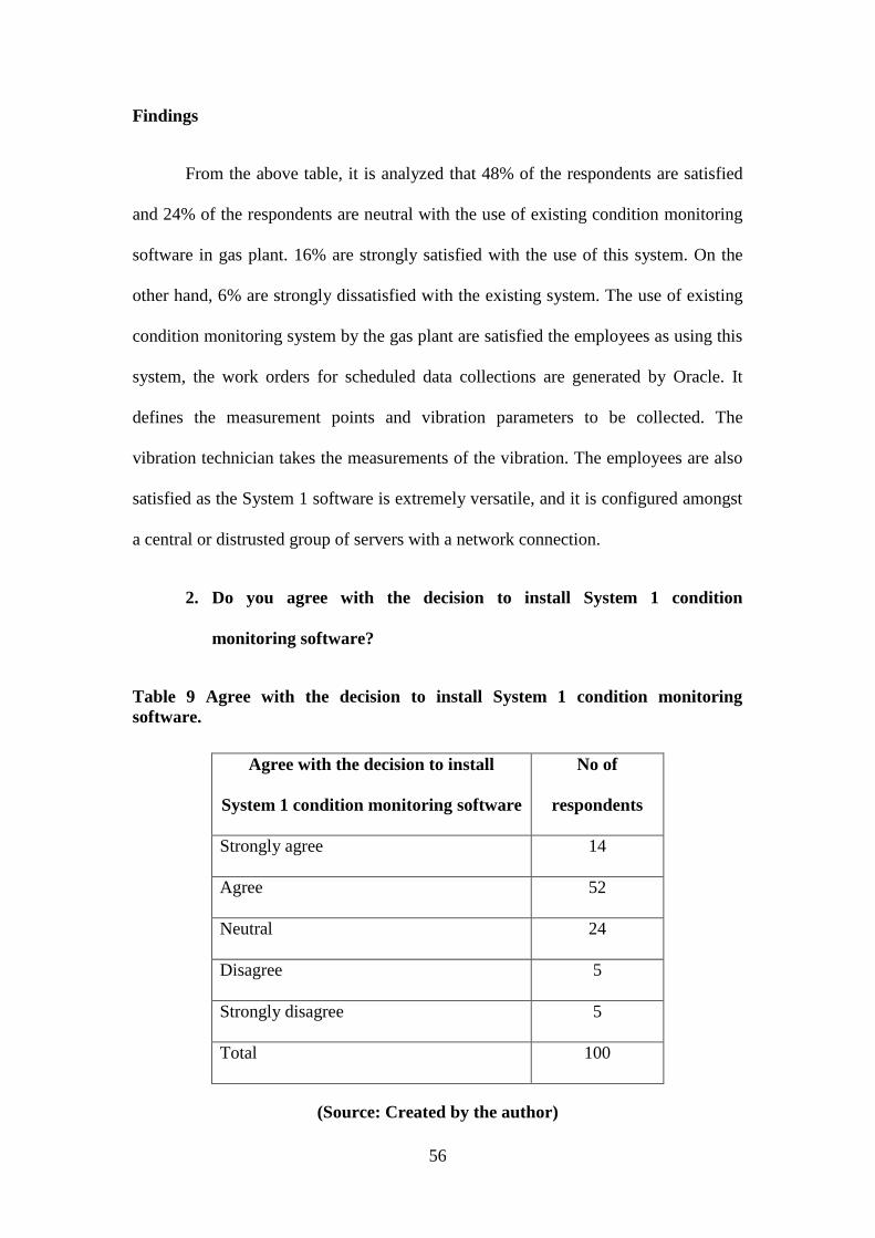
56
Findings
From the above table, it is analyzed that 48% of the respondents are satisfied
and 24% of the respondents are neutral with the use of existing condition monitoring
software in gas plant. 16% are strongly satisfied with the use of this system. On the
other hand, 6% are strongly dissatisfied with the existing system. The use of existing
condition monitoring system by the gas plant are satisfied the employees as using this
system, the work orders for scheduled data collections are generated by Oracle. It
defines the measurement points and vibration parameters to be collected. The
vibration technician takes the measurements of the vibration. The employees are also
satisfied as the System 1 software is extremely versatile, and it is configured amongst
a central or distrusted group of servers with a network connection.
2. Do you agree with the decision to install System 1 condition
monitoring software?
Table 9 Agree with the decision to install System 1 condition monitoring
software.
Agree with the decision to install
System 1 condition monitoring software
No of
respondents
Strongly agree 14
Agree 52
Neutral 24
Disagree 5
Strongly disagree 5
Total 100
(Source: Created by the author)
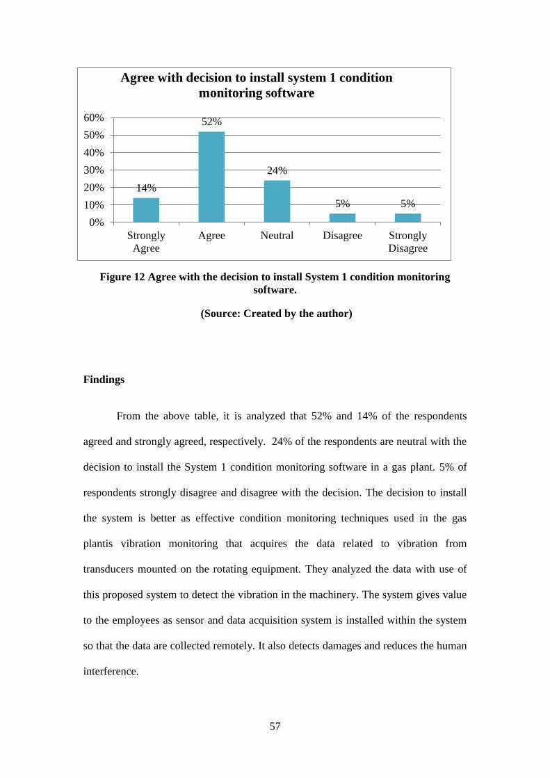
57
Figure 12 Agree with the decision to install System 1 condition monitoring
software.
(Source: Created by the author)
Findings
From the above table, it is analyzed that 52% and 14% of the respondents
agreed and strongly agreed, respectively. 24% of the respondents are neutral with the
decision to install the System 1 condition monitoring software in a gas plant. 5% of
respondents strongly disagree and disagree with the decision. The decision to install
the system is better as effective condition monitoring techniques used in the gas
plantis vibration monitoring that acquires the data related to vibration from
transducers mounted on the rotating equipment. They analyzed the data with use of
this proposed system to detect the vibration in the machinery. The system gives value
to the employees as sensor and data acquisition system is installed within the system
so that the data are collected remotely. It also detects damages and reduces the human
interference.
14%
52%
24%
5% 5%
0%
10%
20%
30%
40%
50%
60%
Strongly
Agree
Agree Neutral Disagree Strongly
Disagree
Agree with decision to install system 1 condition
monitoring software
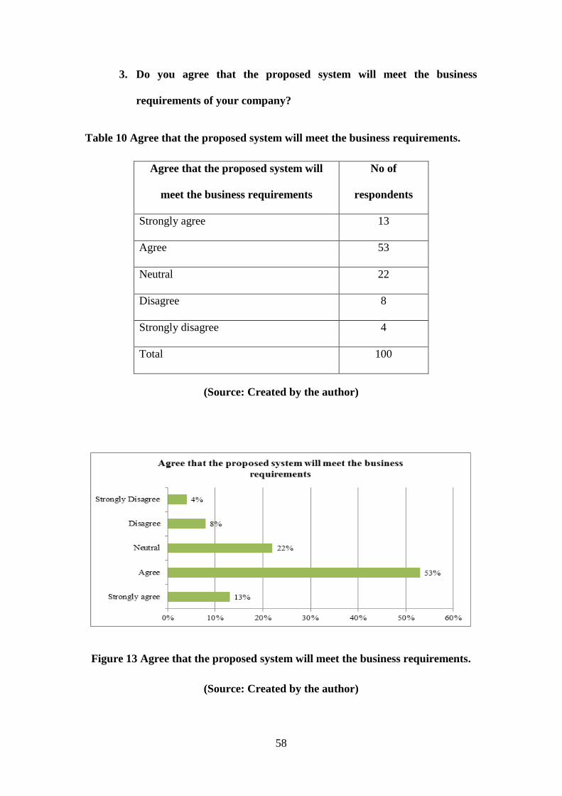
58
3. Do you agree that the proposed system will meet the business
requirements of your company?
Table 10 Agree that the proposed system will meet the business requirements.
Agree that the proposed system will
meet the business requirements
No of
respondents
Strongly agree 13
Agree 53
Neutral 22
Disagree 8
Strongly disagree 4
Total 100
(Source: Created by the author)
Figure 13 Agree that the proposed system will meet the business requirements.
(Source: Created by the author)
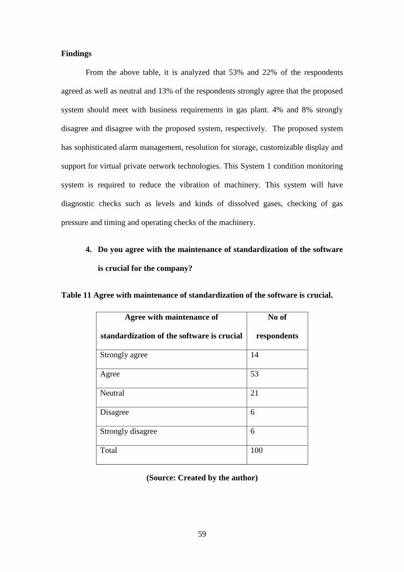
59
Findings
From the above table, it is analyzed that 53% and 22% of the respondents
agreed as well as neutral and 13% of the respondents strongly agree that the proposed
system should meet with business requirements in gas plant. 4% and 8% strongly
disagree and disagree with the proposed system, respectively. The proposed system
has sophisticated alarm management, resolution for storage, customizable display and
support for virtual private network technologies. This System 1 condition monitoring
system is required to reduce the vibration of machinery. This system will have
diagnostic checks such as levels and kinds of dissolved gases, checking of gas
pressure and timing and operating checks of the machinery.
4. Do you agree with the maintenance of standardization of the software
is crucial for the company?
Table 11 Agree with maintenance of standardization of the software is crucial.
Agree with maintenance of
standardization of the software is crucial
No of
respondents
Strongly agree 14
Agree 53
Neutral 21
Disagree 6
Strongly disagree 6
Total 100
(Source: Created by the author)
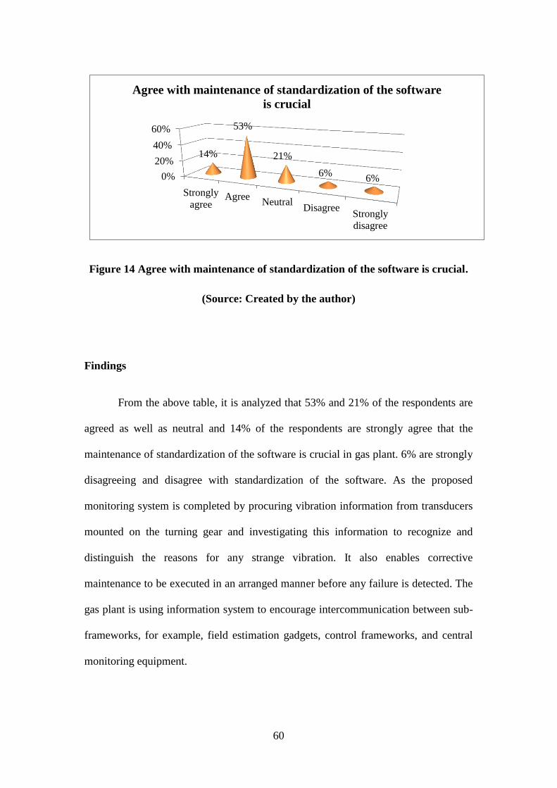
60
Figure 14 Agree with maintenance of standardization of the software is crucial.
(Source: Created by the author)
Findings
From the above table, it is analyzed that 53% and 21% of the respondents are
agreed as well as neutral and 14% of the respondents are strongly agree that the
maintenance of standardization of the software is crucial in gas plant. 6% are strongly
disagreeing and disagree with standardization of the software. As the proposed
monitoring system is completed by procuring vibration information from transducers
mounted on the turning gear and investigating this information to recognize and
distinguish the reasons for any strange vibration. It also enables corrective
maintenance to be executed in an arranged manner before any failure is detected. The
gas plant is using information system to encourage intercommunication between sub-
frameworks, for example, field estimation gadgets, control frameworks, and central
monitoring equipment.
0%
20%
40%
60%
Strongly
agreeAgree
NeutralDisagree
Strongly
disagree
14%
53%
21%
6% 6%
Agree with maintenance of standardization of the software
is crucial
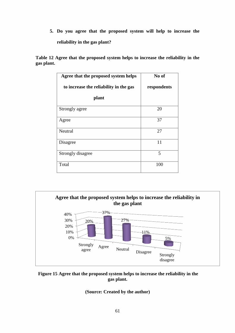
61
5. Do you agree that the proposed system will help to increase the
reliability in the gas plant?
Table 12 Agree that the proposed system helps to increase the reliability in the
gas plant.
Agree that the proposed system helps
to increase the reliability in the gas
plant
No of
respondents
Strongly agree 20
Agree 37
Neutral 27
Disagree 11
Strongly disagree 5
Total 100
Figure 15 Agree that the proposed system helps to increase the reliability in the
gas plant.
(Source: Created by the author)
0%
10%
20%
30%
40%
Strongly
agreeAgree
NeutralDisagree
Strongly
disagree
20%
37%
27%
11%
5%
Agree that the proposed system helps to increase the reliability in
the gas plant
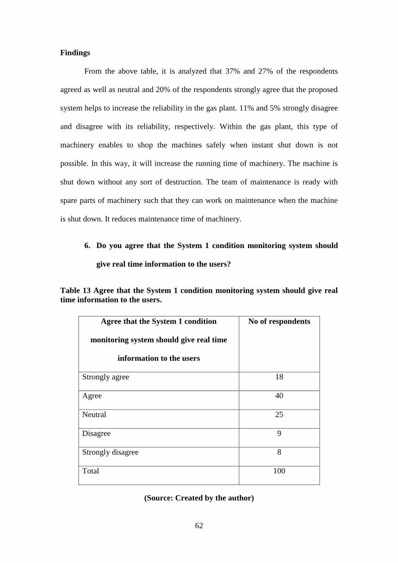
62
Findings
From the above table, it is analyzed that 37% and 27% of the respondents
agreed as well as neutral and 20% of the respondents strongly agree that the proposed
system helps to increase the reliability in the gas plant. 11% and 5% strongly disagree
and disagree with its reliability, respectively. Within the gas plant, this type of
machinery enables to shop the machines safely when instant shut down is not
possible. In this way, it will increase the running time of machinery. The machine is
shut down without any sort of destruction. The team of maintenance is ready with
spare parts of machinery such that they can work on maintenance when the machine
is shut down. It reduces maintenance time of machinery.
6. Do you agree that the System 1 condition monitoring system should
give real time information to the users?
Table 13 Agree that the System 1 condition monitoring system should give real
time information to the users.
Agree that the System 1 condition
monitoring system should give real time
information to the users
No of respondents
Strongly agree 18
Agree 40
Neutral 25
Disagree 9
Strongly disagree 8
Total 100
(Source: Created by the author)
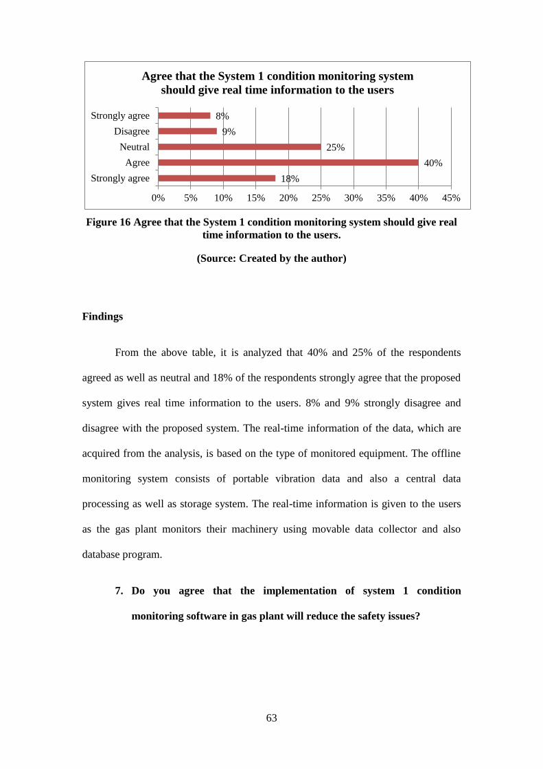
63
Figure 16 Agree that the System 1 condition monitoring system should give real
time information to the users.
(Source: Created by the author)
Findings
From the above table, it is analyzed that 40% and 25% of the respondents
agreed as well as neutral and 18% of the respondents strongly agree that the proposed
system gives real time information to the users. 8% and 9% strongly disagree and
disagree with the proposed system. The real-time information of the data, which are
acquired from the analysis, is based on the type of monitored equipment. The offline
monitoring system consists of portable vibration data and also a central data
processing as well as storage system. The real-time information is given to the users
as the gas plant monitors their machinery using movable data collector and also
database program.
7. Do you agree that the implementation of system 1 condition
monitoring software in gas plant will reduce the safety issues?
18%
40%
25%
9%
8%
0% 5% 10% 15% 20% 25% 30% 35% 40% 45%
Strongly agree
Agree
Neutral
Disagree
Strongly agree
Agree that the System 1 condition monitoring system
should give real time information to the users
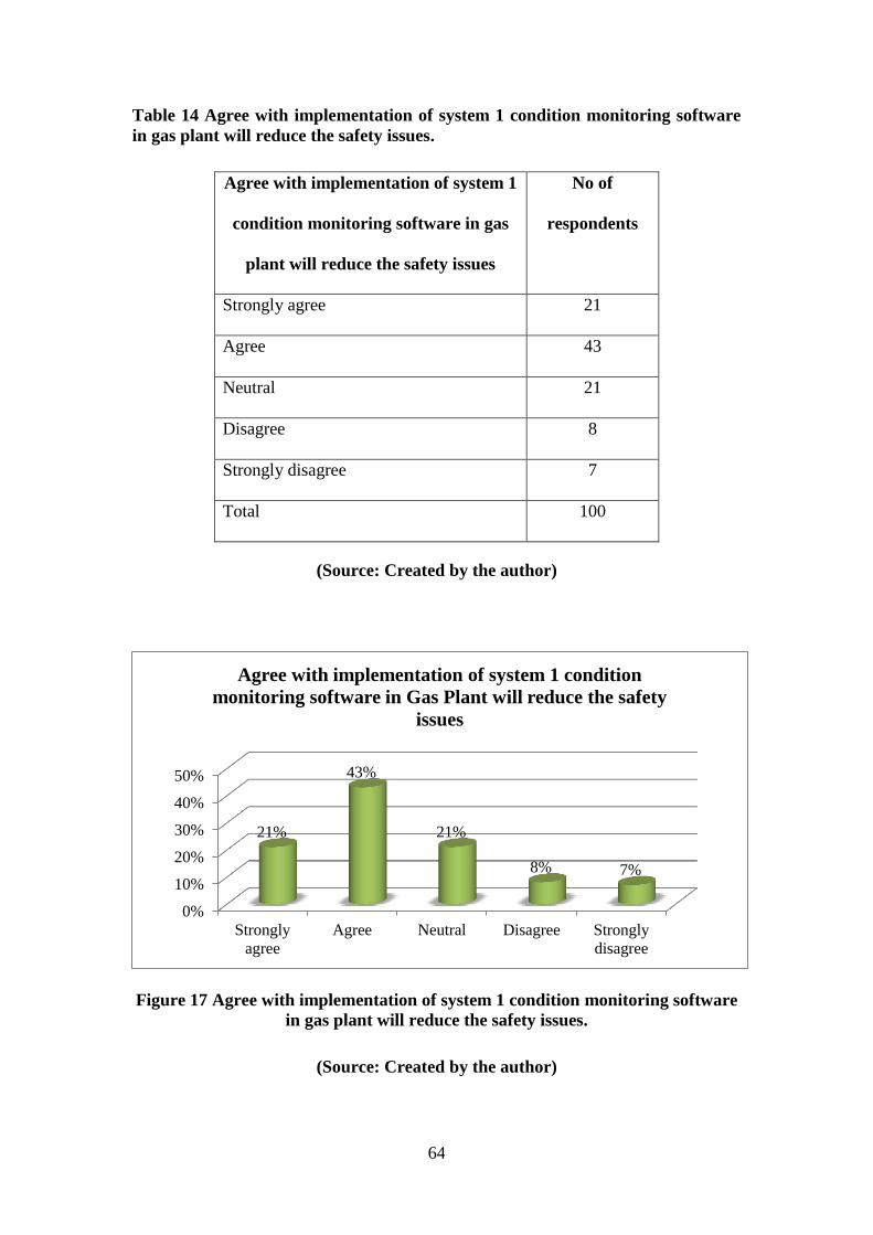
64
Table 14 Agree with implementation of system 1 condition monitoring software
in gas plant will reduce the safety issues.
Agree with implementation of system 1
condition monitoring software in gas
plant will reduce the safety issues
No of
respondents
Strongly agree 21
Agree 43
Neutral 21
Disagree 8
Strongly disagree 7
Total 100
(Source: Created by the author)
Figure 17 Agree with implementation of system 1 condition monitoring software
in gas plant will reduce the safety issues.
(Source: Created by the author)
0%
10%
20%
30%
40%
50%
Strongly
agree
Agree Neutral Disagree Strongly
disagree
21%
43%
21%
8% 7%
Agree with implementation of system 1 condition
monitoring software in Gas Plant will reduce the safety
issues
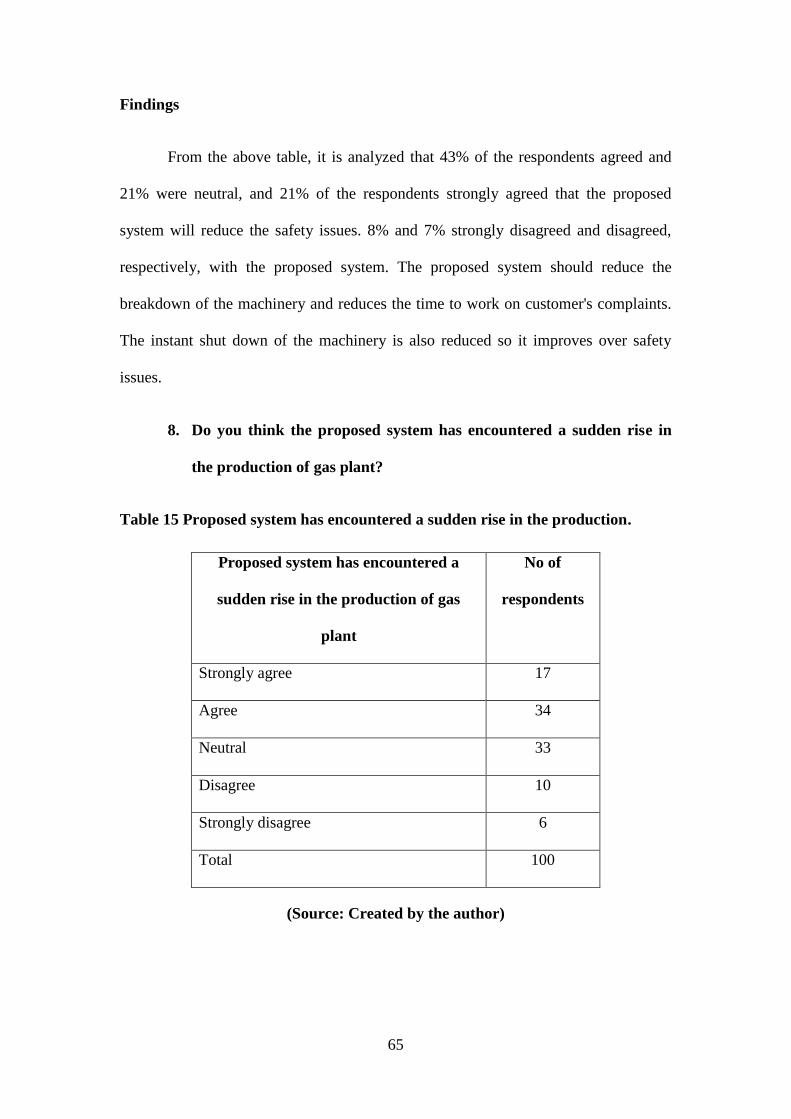
65
Findings
From the above table, it is analyzed that 43% of the respondents agreed and
21% were neutral, and 21% of the respondents strongly agreed that the proposed
system will reduce the safety issues. 8% and 7% strongly disagreed and disagreed,
respectively, with the proposed system. The proposed system should reduce the
breakdown of the machinery and reduces the time to work on customer's complaints.
The instant shut down of the machinery is also reduced so it improves over safety
issues.
8. Do you think the proposed system has encountered a sudden rise in
the production of gas plant?
Table 15 Proposed system has encountered a sudden rise in the production.
Proposed system has encountered a
sudden rise in the production of gas
plant
No of
respondents
Strongly agree 17
Agree 34
Neutral 33
Disagree 10
Strongly disagree 6
Total 100
(Source: Created by the author)
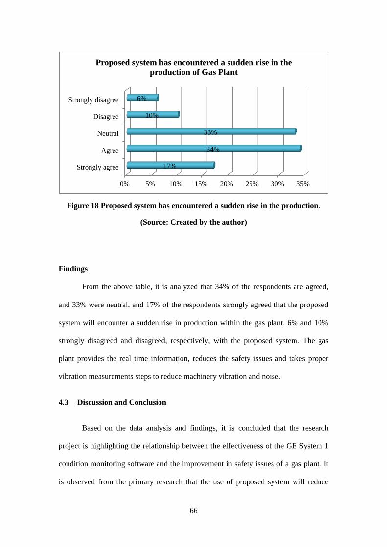
66
Figure 18 Proposed system has encountered a sudden rise in the production.
(Source: Created by the author)
Findings
From the above table, it is analyzed that 34% of the respondents are agreed,
and 33% were neutral, and 17% of the respondents strongly agreed that the proposed
system will encounter a sudden rise in production within the gas plant. 6% and 10%
strongly disagreed and disagreed, respectively, with the proposed system. The gas
plant provides the real time information, reduces the safety issues and takes proper
vibration measurements steps to reduce machinery vibration and noise.
4.3 Discussion and Conclusion
Based on the data analysis and findings, it is concluded that the research
project is highlighting the relationship between the effectiveness of the GE System 1
condition monitoring software and the improvement in safety issues of a gas plant. It
is observed from the primary research that the use of proposed system will reduce
0% 5% 10% 15% 20% 25% 30% 35%
Strongly agree
Agree
Neutral
Disagree
Strongly disagree
17%
34%
33%
10%
6%
Proposed system has encountered a sudden rise in the
production of Gas Plant
67
errors in the machinery and vibration reduction. The entire research study describes
the response of the employees as well as managers working in the gas plant. It is done
so that their feedback can be analyzed to identify if the proposed system will be
beneficial for the company. From the entire research, it is analyzed that most of the
respondents are employees and most of them are satisfied with the use of the
proposed condition monitoring system.
The majority of people who have agreed to the integration are end users of the
final data from System 1 and prefer a more accurate and usable information for their
daily work. Almost everyone was appealed by the fact that there will be improved
safety and operational reliability.
The majority of people who have disagreed to the integration are analysts and
data gatherers who see the integration as yet another are to be become trained and
familiar with. Their ways of working may change or worse still their role may become
redundant.
Providing good training and continued support could influence this group to
change their mind. It will be at least 3 to 4 years before the complete benefit of this
integration can be realised. Hence redundancy is not an immediate threat.
68
CHAPTER 5. CONCLUSIONS AND RECOMMENDATIONS
5.1 Summary
The entire research study is focused on performing a feasibility study of the
effectiveness GE System 1 online condition monitoring system in the gas plant. As
cited from the entire research, the use of this advanced condition monitoring system
helps to reduce the unpredictable shutdown that occurs in the machinery by
continuous monitoring and advanced analysis. Sometimes, the vibration causes high
sound levels and harms the health of the employees working in the organization.
Therefore, this system will reduce the noise and gives a peaceful environment to the
employees working in the gas plant. The new desired system is relying on the concept
to reduce noise and vibration and providing a secured and comfortable working
environment. This particular chapter, Conclusion and Recommendations presents a
conclusion on the research issues and problems based on selected topic. It also
presents recommendations on using the System 1 continuous condition monitoring
system for gas plant such that they can predict the fault and vibration in the machinery
before they arise. Finally, area of future study is also analyzed such that the reader can
investigate the use of the proposed system in the future.
5.2 Conclusions about the research problem
In order to reduce and control excessive vibration of the machinery and
equipment, Bently Nevada condition monitoring systems are used. The other research
problem is that of implementation cost to install the condition monitoring system is
high, therefore, before implementing the process, the research analyst conducts a cost-
benefit analysis to estimate the capital and operational expenditure required for
69
implementing an online condition-monitoring network. It would save gas plant money
over the plant’s operational life. Project schedule is also done so that the employees,
managers and research analyst can identify the total time required to conduct the
study. Estimation of labour for installation of network hardware is also required to
overcome the limitations of resource management. Therefore, time for permitting
operator consultation, and walking to the site are also estimated properly before
starting the plan. Selection of proper vendors and the software should be licensed
properly so that the proposed software can be properly installed into the gas plant.
5.3 Implications for theory
One of the vital implications on this convergent study is that this model serves
as a productive framework from which the research analyst’s conceptions on solving
of problem are detailed. In this study, attention is paid if the observations can be
generalized across the comparable samples. The observational reliability with the
findings in previous stages yields a generalized means over the samples within same
population.
5.4 Recommendations
The following recommendations are suggested:
Advanced BN condition monitoring network: A network dedicated to
monitoring the performance of rotating equipment. If the network fails, the
online critical data collection analysis and health monitoring will operate as
normal and alert issues automatically.
Online condition monitoring: Online condition monitoring provides constant,
real-time data collection. By comparison, offline vibration data collection only
ever gives a snapshot of machinery performance – it does not provide a
continuous data visibility, nor necessarily capture the unique vibration
70
signatures of equipment during start-up, loading or shutdown. While data is
collected at two-monthly intervals, within the potential-to-failure (P-F)
interval for common failure modes of rotating equipment, offline collection
introduces an inherent lag between when data is collected and when it can be
viewed and trended for fault diagnosis. Thus earlier defect identification is
enabled with online monitoring. The use of continuous monitoring will also
result in increased reliability of heavy machinery, extended machine life,
reduction in downtime which means increased production, and less operating
costs.
Back up in case the online mode fails: Over reliance on the online mode can
be disastrous. Certainly along the operational journey of the GE system 1 will
face some technical hitches. To avoid such an unfortunate scenario, there
should be an offline back up assistant and this must be brought on board few
seconds after the online mode fails to avoid unnecessarily costly maintenance
due to unmanned monitoring.
Training of operators in the use of the system
Operators are the major custodians of the said system hence they must be
involved at every stage of implementation. They need to be prepared on the
technicalities involved in the implementation of the said system hence they
should thoroughly be trained on the operation and maintenance of the online
monitoring mode.
5.5 Areas of further study
It is identified that there is a chance of further study on the selected research
topic as the high-criticality equipment on gas plant would migrate to a completely
online condition monitoring strategy in the near future. This will eliminate the need
for manual data collection from BN units using portable devices. Instead, vibration
data will be transmitted from BN units across the gas plant data network, so it can be
stored on System 1 servers and trended to enable predictive maintenance.
Additionally, there is need to pursue further the inter-switching fashion of the online

71
and offline modes as failure is inevitable hence the plant must be cushioned against
unnecessary disruptions.
72
REFERENCES
[1] 3500 Monitoring System Rack Installation and Maintenance Manual, 3500
Monitoring System Rack Installation and Maintenance Manual, 2000.
[2] K. Adachi and T. Sakamoto, “Experimental Performance Evaluation of Vibration
Monitoring Sensor Prototype Driven by Piezocomposite Vibration Energy
Harvester Under Low Intensity Excitation Condition”, In ASME 2013
Conference on Smart Materials, Adaptive Structures and Intelligent Systems (pp.
V002T07A026-V002T07A026). American Society of Mechanical Engineers,
2013.
[3] F. Anyan, “The influence of power shifts in data collection and analysis stages: A
focus on qualitative research interview” The Qualitative Report, 18(18), 1, 2013.
[4] C. Atzberger, “Advances in remote sensing of agriculture: Context description,
existing operational monitoring systems and major information needs”, Remote
Sensing, 5(2), 949-981, 2013.
[5] A. Bahga and V.K. Madisetti, “Analyzing massive machine maintenance data in a
computing cloud” IEEE Transactions on Parallel and Distributed
Systems, 23(10), 1831-1843, 2012.
[6] R.L. Baskerville and A.T. Wood-Harper, “A critical perspective on action
research as a method for information systems research”, In Enacting Research
Methods in Information Systems: Volume 2 (pp. 169-190). Springer International
Publishing, 2016.
73
[7] J.L. Bentley, A.S. Krishnakumar and S. Yajnik, U.S. Patent No. 8,774,368.
Washington, DC: U.S. Patent and Trademark Office, 2014.
[8] J. Carroll, A. May, A. McDonald, and D. McMillan, Availability Improvements
From Condition Monitoring Systems and Performance Based Maintenance
Contracts. Submitted to EWEA Offshore, 2015.
[9] J.W. Creswell, Research design: Qualitative, quantitative, and mixed methods
approaches. Sage publications, 2013.
[10] J. Dybała and S. Radkowski, “Reduction of Doppler effect for the needs of
wayside condition monitoring system of railway vehicles”, Mechanical Systems
and Signal Processing, 38(1), 125-136, 2013.
[11] G.E. Energy, System 1 Optimization and Diagnostic Platform, 2005.
[12] M. Englander, “The interview: Data collection in descriptive phenomenological
human scientific research”, Journal of Phenomenological Psychology, 43(1), 13-
35, 2012.
[13] T. Freeman, B. Thom and S. Smith, Noise and Vibration Development for
Adapting a Conventional Vehicle Platform for an Electric Powertrain (No. 2013-
01-2003). SAE Technical Paper, 2013.
[14] GE Energy Measurement & Control Solutions,. Solutions for LNG Facilities
Bently Nevada* Asset Condition Monitoring. GE Energy Measurement &
Control Solutions, 2015.
[15] M. Gizelska, “Sensors and Measuring Systems in the Diagnostics of Mechatronic
Rotating Systems”, system, 4(5), 6, 2015.
74
[16] V.C. Gungor, D. Sahin, T. Kocak, S. Ergut, C. Buccella, C. Cecati and G.P.
Hancke, “A survey on smart grid potential applications and communication
requirements”, IEEE Transactions on Industrial Informatics,9(1), 28-42, 2013.
[17] R. Isermann, Digital control systems. Springer Science & Business Media, 2013.
[18] Y.O. Jung and Y. Bae, “Analysis of Fault Diagnosis for Current and Vibration
Signals in Pumps and Motors using a Reconstructed Phase Portrait”, International
Journal of Fuzzy Logic and Intelligent Systems, 15(3), 166-171, 2015.
[19] D. Kateris, D. Moshou, X.E. Pantazi, I. Gravalos, N. Sawalhi and S. Loutridis, “A
machine learning approach for the condition monitoring of rotating
machinery” Journal of Mechanical Science and Technology, 28(1), 61-71, 2014.
[20] S.D. T. Kelly, N.K. Suryadevara and S.C. Mukhopadhyay, “Towards the
implementation of IoT for environmental condition monitoring in homes”, IEEE
Sensors Journal, 13(10), 3846-3853, 2013.
[21] S.H. Kim, L.S. Hwang, Y.J. Joo, S.U. Lee, B.M. Shon and M. Oh, “Process
Modeling System of a Combined Cycle Plant for Steady State Simulation with
Model Based Approach”, Korean Chemical Engineering Research, 53(5), 545-
552, 2015.
[22] A. Kingsmill, S. Jones and J. Zhu, Application of new condition monitoring
technologies in the electricity transmission industry. InElectrical Machines and
Systems, 2003. ICEMS 2003. Sixth International Conference on (Vol. 2, pp. 852-
855). IEEE, 2003.
[23] J.P. Kong, C.A. Lickteig and R.F. Parchewsky, U.S. Patent No. 8,749,372.
Washington, DC: U.S. Patent and Trademark Office, 2014.
75
[24] G.G. Kulikov and H.A. Thompson, Dynamic modelling of gas turbines:
identification, simulation, condition monitoring and optimal control. Springer
Science & Business Media, 2013.
[25] J. Lee, F. Wu, W. Zhao, M. Ghaffari, L. Liao and D. Siegel, “Prognostics and
health management design for rotary machinery systems—Reviews, methodology
and applications”, Mechanical systems and signal processing, 42(1), 314-334,
2014.
[26] S. Lewis, Qualitative inquiry and research design: Choosing among five
approaches. Health promotion practice, 1524839915580941, 2015.
[27] H. Luo, R. Chumai, N. Peton, B. Howard and A. Menon, “Torsional vibration
detection using high sampling rate and high resolution keyphasor information”,
In ASME 2013 International Design Engineering Technical Conferences and
Computers and Information in Engineering Conference (pp. V008T13A001-
V008T13A001). American Society of Mechanical Engineers, 2013.
[28] T. Marwala, Condition monitoring using computational intelligence methods:
applications in mechanical and electrical systems. Springer Science & Business
Media, 2012.
[29] J. Mathew, “Machine condition monitoring using vibration analysis”, Journal of
the Australia Acoustical Society, 15(1), 7-13, 1987.
[30] M.J. Neale and B.J. Woodley, Condition monitoring methods and economics.
In Symposium of the Society of Environmental Engineers, London, 1975.
76
[31] A. Perek and W. Kurnik, “Kinematically Excited Vibration of an Asymmetric
Rotor/Bearing System With Magnetic Lubricant”, Machine Dynamics
Research, 39(4), 2016.
[32] M.N. Pham and H.J. Ahn, “Experimental optimization of a hybrid foil–magnetic
bearing to support a flexible rotor”, Mechanical Systems and Signal
Processing, 46(2), 361-372, 2014.
[33] E.I. Prest, F. Hammes, S. Kötzsch, M.C.M. Van Loosdrecht and J.S.
Vrouwenvelder, “Monitoring microbiological changes in drinking water systems
using a fast and reproducible flow cytometric method”, Water research, 47(19),
7131-7142, 2013.
[34] F. Serdio, E. Lughofer, K. Pichler, T. Buchegger and H. Efendic, “Residual-based
fault detection using soft computing techniques for condition monitoring at
rolling mills”, Information Sciences, 259, 304-320, 2014.
[35] J.A. Smith, Qualitative psychology: A practical guide to research methods. Sage,
2015.
[36] S. Smith, N. Palfreeman, M. Mashour and G. Seefeldt, Smokeless Air Assist and
Flare Gas Recovery Technology for Continuous Flare Management, 2013.
[37] J. Sun, H. Zuo, W. Wang and M.G. Pecht, “Application of a state space modeling
technique to system prognostics based on a health index for condition-based
maintenance”, Mechanical Systems and Signal Processing,28, 585-596, 2012.
[38] L. Xiang, S. Yang and C. Gan, “Torsional vibration measurements on rotating
shaft system using laser dopplervibrometer”, Optics and Lasers in
Engineering, 50(11), 1596-1601, 2012.
77
[39] K. W. Yun. Profitability, Failure Modes and Risk Assessment of Rotary
Compressor under Extraordinary Operating Conditions. reliability and condition
based monitoring of LNG floating platforms: A review. United Technologies
Carrier Corporation c/o Daewoo Carner Corporation
Kwangju,Korea.2000.[Online].Available:http://docs.lib.purdue.edu/cgi/viewconte
nt.cgi?article=2381&context=icec
[40] Samer Gowid, Roger Dixon and Saud Ghan. Profitability, reliability and
condition based monitoring of LNG floating platforms: A review
[41] J.G. Salazar and I.F. Santos, “Feedback-controlled lubrication for reducing the
lateral vibration of flexible rotors supported by tilting-pad journal
bearings”, Proceedings of the Institution of Mechanical Engineers, Part J: Journal
of Engineering Tribology, 229(10), 1264-1275, 2015.
[42] M. Schlechtingen, I.F. Santos and S. Achiche, “Wind turbine condition
monitoring based on SCADA data using normal behavior models. Part 1: System
description”, Applied Soft Computing, 13(1), 259-270, 2013.
[43] B. Sheikman, J.E. Howard, B. Rank and R.V. Jensen, U.S. Patent No. 8,344,741.
Washington, DC: U.S. Patent and Trademark Office, 2013.
[44] S. Sheng, Investigation of Various Condition Monitoring Techniquest Based on a
Damaged Wind Turbine Gearbox. National Renewable Energy Laboratory, US
Department of Energy, Office of Energy Efficiency and Renewable Energy, 2011.
[45] P.P.L. Sue, B.F.I. Lawrence and A.B. Kretschmar, U.S. Patent No. 8,910,531.
Washington, DC: U.S. Patent and Trademark Office, 2014.

78
[46] J. Sun, H. Zuo, W. Wang and M.G. Pecht, “Application of a state space modeling
technique to system prognostics based on a health index for condition-based
maintenance”, Mechanical Systems and Signal Processing,28, 585-596, 2012.
[47] D.N.Brown & T.Jensen and Briiel & Kjaer The use of Spectrum Comparison for
Bearing Fault Detection - A Case Study from Alma Paper Mill, Quebec, Canada

79
APPENDICES
1. Survey Questionnaire
1. Please indicate the age group
Under 25
26-39
40-49
Above 50
2. Please select your gender
Male
Female
3. Please select your designation *
Project Manager
Employee
IT Manager
System Analyst
Feasibility study on effectiveness of proposed system
1. How long have you been working at the gas plant?
Less than 1 year
1 – 3 years
3 – 5 years
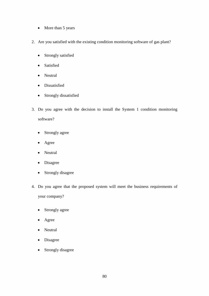
80
More than 5 years
2. Are you satisfied with the existing condition monitoring software of gas plant?
Strongly satisfied
Satisfied
Neutral
Dissatisfied
Strongly dissatisfied
3. Do you agree with the decision to install the System 1 condition monitoring
software?
Strongly agree
Agree
Neutral
Disagree
Strongly disagree
4. Do you agree that the proposed system will meet the business requirements of
your company?
Strongly agree
Agree
Neutral
Disagree
Strongly disagree

81
5. Do you agree with maintenance of standardization of the software is crucial for
the company?
Strongly agree
Agree
Neutral
Disagree
Strongly disagree
6. Do you agree that the proposed system helps to increase the reliability in the gas
plant?
Strongly agree
Agree
Neutral
Disagree
Strongly disagree
7. Do you agree that the System 1 condition monitoring system should give real time
information to the users?
• Strongly agree
• Agree
• Neutral
• Disagree
• Strongly disagree
8. Do you agree implementation of system 1 condition monitoring software in gas
plantwill reduce the safety issues?

82
Strongly agree
Agree
Neutral
Disagree
Strongly disagree
9. Do you think the proposed system has encountered a sudden rise in the production
of gas plant?
Strongly agree
Agree
Neutral
Disagree
Strongly disagree