feature manual - g-flex® c7 relay
TRANSCRIPT

Tekelec EAGLE® 5
Feature Manual - G-Flex® C7 Relay910-6255-001 Revision A
January 2012
Copyright 2012 Tekelec. All Rights Reserved. Printed in USA.Legal Information can be accessed from the Main Menu of the optical disc or on the
Tekelec Customer Support web site in the Legal Information folder of the Product Support tab.
Table of Contents
Chapter 1: Introduction.......................................................................7Overview....................................................................................................................................8Scope and Audience.................................................................................................................8Manual Organization................................................................................................................8Documentation Admonishments............................................................................................9Customer Care Center..............................................................................................................9Emergency Response..............................................................................................................12Related Publications...............................................................................................................12Documentation Availability, Packaging, and Updates.....................................................12Locate Product Documentation on the Customer Support Site.......................................13
Chapter 2: G-Flex C7 Relay (G-Flex) Feature................................14Introduction.............................................................................................................................15G-Flex Feature Description....................................................................................................15
Number Conditioning................................................................................................16G-Flex Call Flows........................................................................................................16G-Flex Relay Function Description...........................................................................19MTP-Routed SCCP Message Processing.................................................................25G-Flex Configuration Options...................................................................................26DigitAction Expansion...............................................................................................28G-Flex SCCP Service Re-Route Capability..............................................................29G-Flex in an ANSI Environment...............................................................................33G-Flex as a "Stand-Alone" Node...............................................................................33Assumptions/Limitations.........................................................................................33
Hardware Requirements........................................................................................................34MPS/EPAP Platform..............................................................................................................34
EPAP/PDBA Overview.............................................................................................36Subscriber Data Provisioning....................................................................................37EPAP (EAGLE Provisioning Application Processor)............................................39Service Module Cards................................................................................................40Network Connections.................................................................................................43
Chapter 3: G-Flex MAP Layer Routing (G-Flex MLR)Feature...............................................................................................48
ii910-6255-001 Revision A, January 2012

G-Flex MAP Layer Routing...................................................................................................49Limitations...............................................................................................................................52
Chapter 4: EAGLE 5 ISS Commands..............................................53EAGLE 5 ISS Commands.......................................................................................................54
Chapter 5: G-Flex Feature Configuration.......................................56Introduction.............................................................................................................................57
EPAP Provisioning Blacklist......................................................................................57EPAP Entity Provisioning..........................................................................................58System Prerequisites...................................................................................................58G-Flex Feature Prerequisites......................................................................................59G-Flex MAP Layer Routing Feature Prerequisites.................................................59
G-Flex and G-Flex MLR Configuration Procedure............................................................60Configure the System for HLR Destinations.......................................................................62Adding a Service Module Card............................................................................................63Enable and Turn on the G-Flex Feature...............................................................................70Provision STPOPTS Options for G-Flex...............................................................................71Provisioning the G-Flex Service Selector.............................................................................72
Adding a G-Flex Service Selector..............................................................................72Removing a Service Selector......................................................................................74Changing an Existing Service Selector to a G-Flex Service Selector....................74
Provision the STPOPTS ANSIGFLEX Option.....................................................................76Provisioning the GSMOPTS Options...................................................................................77Provision the SCCP Service State and Point Codes...........................................................78Enable and Turn on the G-Flex MLR Feature.....................................................................79The 1100 TPS/DSM for ITU NP Feature.............................................................................80
Enable the 1100 TPS/DSM for ITU NP Feature......................................................83Turn On the 1100 TPS/DSM for ITU NP Feature..................................................83Turn Off the 1100 TPS/DSM for ITU NP Feature..................................................84
Activating the E5-SM4G Throughput Capacity Feature...................................................84
Chapter 6: Measurements..................................................................89G-Flex Measurements.............................................................................................................90
Chapter 7: Maintenance.....................................................................92G-Flex-Related Alarms...........................................................................................................93G-Flex-Related UIMs..............................................................................................................93Maintenance Commands.......................................................................................................95
iii910-6255-001 Revision A, January 2012

rept-stat-sccp................................................................................................................97Debug Commands..................................................................................................................97Status Reporting and Problem Identification......................................................................98
EPAP Status and Alarm Reporting.........................................................................100Hourly Maintenance Report....................................................................................101
Glossary..................................................................................................................103
iv910-6255-001 Revision A, January 2012

List of FiguresFigure 1: E.214 (E.212) Routing Example - Location Updating....................................................18Figure 2: Mobile Terminated Call.....................................................................................................19Figure 3: G-Flex in SCCP....................................................................................................................20Figure 4: MPS/EPAP Platform Architecture..................................................................................35Figure 5: Subscriber Data Provisioning Architecture (High Level).............................................38Figure 6: Database Administrative Architecture............................................................................40Figure 7: Customer Provisioning Network.....................................................................................44Figure 8: EPAP Sync Network..........................................................................................................45Figure 9: DSM Networks....................................................................................................................46Figure 10: Dial-Up PPP Network......................................................................................................47
v910-6255-001 Revision A, January 2012

List of TablesTable 1: Admonishments.....................................................................................................................9Table 2: G-Flex Relay Data Combinations.......................................................................................21Table 3: National/Local Numbers to International Numbers Conversion Logic.....................21Table 4: G-Flex Relay Forwarding Message: MTP Portion...........................................................23Table 5: G-Flex Relay Forwarding Message: SCCP Portion..........................................................24Table 6: GSMOPTS Configuration Options for G-Flex and G-Flex MLR...................................26Table 7: DigitAction Applications....................................................................................................28Table 8: G-Flex SCCP Re-Route Message Handling Summary....................................................31Table 9: G-Flex LIM Card Re-Route Message Handling Summary.............................................32Table 10: Service Module Card Provisioning and Reload Settings..............................................42Table 11: EPAP IP Addresses in the DSM Network......................................................................46Table 12: MAP Operations Processed by G-Flex MLR..................................................................49Table 13: GSMOPTS Configuration Options MAPLYRRTGON and MAPLYRRTGOFF........50Table 14: Commands used for the G-Flex and G-Flex MLR Features.........................................54Table 15: System Prerequisites..........................................................................................................58Table 16: G-Flex Feature Prerequisites.............................................................................................59Table 17: G-Flex MAP Layer Routing Feature Prerequisites........................................................60Table 18: Service Module Card Locations.......................................................................................64Table 19: System Prerequisites for Adding a Service Module Card............................................64Table 20: Prerequisite for Adding an E5-SM4G Service Module Card.......................................65Table 21: Prerequisites for Adding an E5-SM8G-B Service Module Card..................................65Table 22: System Prerequisites..........................................................................................................81Table 23: Feature Prerequisites..........................................................................................................82Table 24: Maximum E5-SM4G, E5-SM8G-B, and System TPS Capacity.....................................85Table 25: System Prerequisites..........................................................................................................86Table 26: E5-SM4G Throughput Capacity Feature Prerequisite..................................................87Table 27: G-Flex MSU Measurements..............................................................................................90Table 28: STP Daily and Day-to-Hour Measurements that include Counts for G-Flex
MSUs...............................................................................................................................................91Table 29: G-Flex-Related Alarms......................................................................................................93Table 30: G-Flex UIMs........................................................................................................................94Table 31: Maintenance Commands...................................................................................................96Table 32: Status Reporting for EPAP-Related Features.................................................................98
vi910-6255-001 Revision A, January 2012

Chapter
1Introduction
This chapter contains general information about theG-Flex documentation, the organization of thismanual, and how to get technical assistance.
Topics:
• Overview.....8• Scope and Audience.....8• Manual Organization.....8• Documentation Admonishments.....9• Customer Care Center.....9• Emergency Response.....12• Related Publications.....12• Documentation Availability, Packaging, and
Updates.....12• Locate Product Documentation on the Customer
Support Site.....13
7910-6255-001 Revision A, January 2012
Overview
This manual describes the configuration and operation of the G-Flex® C7 Relay (G-Flex) feature in the
EAGLE 5 ISS (Integrated Signaling System). The G-Flex feature enables efficient Home LocationRegister (HLR) management in ITU networks, ANSI networks, Global System for Mobilecommunications (GSM) networks, and IS-41 networks. G-Flex optimizes the use of subscriber numbersand number ranges by providing a logical link between any MSISDN number or IMSI and an HLR.This arrangement allows subscribers to be moved easily from one HLR to another.
The following G-Flex-related functions are described in this manual:
• The G-Flex Relay function, which provides enhancements to GTT Processing such as numberconditioning, discrimination between G-Flex Relay and GTT processing, and outgoing CdPAmodification. See G-Flex Relay Function Description.
• DigitAction Expansion, which provides flexible rules for formatting the SCCP CdPA GTA field.
• G-Flex SCCP Service Re-Route Capability, which provides the ability to re-route the traffic from oneEAGLE 5 ISS to other G-Flex nodes within an operator's network, and inform the originating nodesto re-route the G-Flex service-related traffic to other G-Flex service nodes.
• G-Flex in an ANSI Environment, which increases the DSM card transaction capacity from 850 TPSto 1700 TPS for G-Flex in an ANSI system.
G-Flex is optional on the EAGLE 5 ISS, and can be turned on, but not off, using a feature part numberand a feature access key. G-Flex and North American LNP (Local Number Portability) are mutuallyexclusive on an EAGLE 5 ISS node. The Global Title Translations (GTT) feature is required for operationof the G-Flex feature.
This manual also describes the use of the G-Flex MAP Layer Routing feature to obtain subscriber digitsfrom either the SCCP layer or MAP layer of a message for RTDB lookup.
Scope and Audience
This manual is intended for anyone responsible for installing, maintaining, and using the G-Flexfeature in the EAGLE 5 ISS. Users of this manual and the others in the EAGLE 5 ISS family of documentsmust have a working knowledge of telecommunications and network installations.
Manual Organization
This document is organized into the following chapters:
• Introduction contains general information about the G-Flex documentation, the organization of thismanual, and how to get technical assistance.
• G-Flex C7 Relay (G-Flex) Feature provides a functional description of G-Flex, including the G-FlexSCCP Service Re-Route Capability and use of G-Flex in an ANSI system.
• G-Flex MAP Layer Routing (G-Flex MLR) Feature describes the use of the G-Flex MAP Layer Routingfeature.
8910-6255-001 Revision A, January 2012
IntroductionFeature Manual - G-Flex® C7 Relay

• EAGLE 5 ISS Commands describes the EAGLE 5 ISS commands that can be used for G-Flex featureconfiguration functions.
• G-Flex Feature Configuration provides procedures for configuring the G-Flex feature, the G-FlexSCCP Service Re-Route Capability, ANSI G-Flex, and the G-Flex MAP Layer Routing feature foruse in the EAGLE 5 ISS.
• Measurements describes G-Flex-related measurements, measurements reports, and methods ofcollection.
• Maintenance describes G-Flex-related UAMs and UIMs; commands that can be used for maintenancefunctions; and status and alarm reporting for the EAGLE 5 ISS, EPAP, Service Module cards,services, and the local subsystem.
Documentation Admonishments
Admonishments are icons and text throughout this manual that alert the reader to assure personalsafety, to minimize possible service interruptions, and to warn of the potential for equipment damage.
Table 1: Admonishments
DANGER:
(This icon and text indicate the possibility of personal injury.)
WARNING:
(This icon and text indicate the possibility of equipment damage.)
CAUTION:
(This icon and text indicate the possibility of service interruption.)
Customer Care Center
The Tekelec Customer Care Center is your initial point of contact for all product support needs. Arepresentative takes your call or email, creates a Customer Service Request (CSR) and directs yourrequests to the Tekelec Technical Assistance Center (TAC). Each CSR includes an individual trackingnumber. Together with TAC Engineers, the representative will help you resolve your request.
The Customer Care Center is available 24 hours a day, 7 days a week, 365 days a year, and is linkedto TAC Engineers around the globe.
Tekelec TAC Engineers are available to provide solutions to your technical questions and issues 7days a week, 24 hours a day. After a CSR is issued, the TAC Engineer determines the classification ofthe trouble. If a critical problem exists, emergency procedures are initiated. If the problem is not critical,normal support procedures apply. A primary Technical Engineer is assigned to work on the CSR andprovide a solution to the problem. The CSR is closed when the problem is resolved.
9910-6255-001 Revision A, January 2012
IntroductionFeature Manual - G-Flex® C7 Relay

Tekelec Technical Assistance Centers are located around the globe in the following locations:
Tekelec - Global
Email (All Regions): [email protected]
• USA and Canada
Phone:
1-888-FOR-TKLC or 1-888-367-8552 (toll-free, within continental USA and Canada)
1-919-460-2150 (outside continental USA and Canada)
TAC Regional Support Office Hours:
8:00 a.m. through 5:00 p.m. (GMT minus 5 hours), Monday through Friday, excluding holidays• Caribbean and Latin America (CALA)
Phone:
USA access code +1-800-658-5454, then 1-888-FOR-TKLC or 1-888-367-8552 (toll-free)
TAC Regional Support Office Hours (except Brazil):
10:00 a.m. through 7:00 p.m. (GMT minus 6 hours), Monday through Friday, excluding holidays
• Argentina
Phone:
0-800-555-5246 (toll-free)• Brazil
Phone:
0-800-891-4341 (toll-free)
TAC Regional Support Office Hours:
8:30 a.m. through 6:30 p.m. (GMT minus 3 hours), Monday through Friday, excluding holidays• Chile
Phone:
1230-020-555-5468• Colombia
Phone:
01-800-912-0537• Dominican Republic
Phone:
1-888-367-8552• Mexico
Phone:
001-888-367-8552
10910-6255-001 Revision A, January 2012
IntroductionFeature Manual - G-Flex® C7 Relay
• Peru
Phone:
0800-53-087• Puerto Rico
Phone:
1-888-367-8552 (1-888-FOR-TKLC)• Venezuela
Phone:
0800-176-6497
• Europe, Middle East, and Africa
Regional Office Hours:
8:30 a.m. through 5:00 p.m. (GMT), Monday through Friday, excluding holidays
• Signaling
Phone:
+44 1784 467 804 (within UK)• Software Solutions
Phone:
+33 3 89 33 54 00
• Asia
• India
Phone:
+91 124 436 8552 or +91 124 436 8553
TAC Regional Support Office Hours:
10:00 a.m. through 7:00 p.m. (GMT plus 5 1/2 hours), Monday through Saturday, excludingholidays
• Singapore
Phone:
+65 6796 2288
TAC Regional Support Office Hours:
9:00 a.m. through 6:00 p.m. (GMT plus 8 hours), Monday through Friday, excluding holidays
11910-6255-001 Revision A, January 2012
IntroductionFeature Manual - G-Flex® C7 Relay
Emergency Response
In the event of a critical service situation, emergency response is offered by the Tekelec Customer CareCenter 24 hours a day, 7 days a week. The emergency response provides immediate coverage, automaticescalation, and other features to ensure that the critical situation is resolved as rapidly as possible.
A critical situation is defined as a problem with the installed equipment that severely affects service,traffic, or maintenance capabilities, and requires immediate corrective action. Critical situations affectservice and/or system operation resulting in one or several of these situations:
• A total system failure that results in loss of all transaction processing capability• Significant reduction in system capacity or traffic handling capability• Loss of the system’s ability to perform automatic system reconfiguration• Inability to restart a processor or the system• Corruption of system databases that requires service affecting corrective actions• Loss of access for maintenance or recovery operations• Loss of the system ability to provide any required critical or major trouble notification
Any other problem severely affecting service, capacity/traffic, billing, and maintenance capabilitiesmay be defined as critical by prior discussion and agreement with the Tekelec Customer Care Center.
Related Publications
For information about additional publications that are related to this document, refer to the RelatedPublications document. The Related Publications document is published as a part of the ReleaseDocumentation and is also published as a separate document on the Tekelec Customer Support Site.
Documentation Availability, Packaging, and Updates
Tekelec provides documentation with each system and in accordance with contractual agreements.For General Availability (GA) releases, Tekelec publishes a complete EAGLE 5 ISS documentation set.For Limited Availability (LA) releases, Tekelec may publish a documentation subset tailored to specificfeature content or hardware requirements. Documentation Bulletins announce a new or updatedrelease.
The Tekelec EAGLE 5 ISS documentation set is released on an optical disc. This format allows for easysearches through all parts of the documentation set.
The electronic file of each manual is also available from the Tekelec Customer Support site. This siteallows for 24-hour access to the most up-to-date documentation, including the latest versions of FeatureNotices.
12910-6255-001 Revision A, January 2012
IntroductionFeature Manual - G-Flex® C7 Relay
Printed documentation is available for GA releases on request only and with a lead time of six weeks.The printed documentation set includes pocket guides for commands and alarms. Pocket guides mayalso be ordered separately. Exceptions to printed documentation are:
• Hardware or Installation manuals are printed without the linked attachments found in the electronicversion of the manuals.
• The Release Notice is available only on the Customer Support site.
Note: Customers may print a reasonable number of each manual for their own use.
Documentation is updated when significant changes are made that affect system operation. Updatesresulting from Severity 1 and 2 Problem Reports (PRs) are made to existing manuals. Other changesare included in the documentation for the next scheduled release. Updates are made by re-issuing anelectronic file to the customer support site. Customers with printed documentation should contacttheir Sales Representative for an addendum. Occasionally, changes are communicated first with aDocumentation Bulletin to provide customers with an advanced notice of the issue until officiallyreleased in the documentation. Documentation Bulletins are posted on the Customer Support site andcan be viewed per product and release.
Locate Product Documentation on the Customer Support Site
Access to Tekelec's Customer Support site is restricted to current Tekelec customers only. This sectiondescribes how to log into the Tekelec Customer Support site and locate a document. Viewing thedocument requires Adobe Acrobat Reader, which can be downloaded at www.adobe.com.
1. Log into the Tekelec Customer Support site.
Note: If you have not registered for this new site, click the Register Here link. Have your customernumber available. The response time for registration requests is 24 to 48 hours.
2. Click the Product Support tab.3. Use the Search field to locate a document by its part number, release number, document name, or
document type. The Search field accepts both full and partial entries.4. Click a subject folder to browse through a list of related files.5. To download a file to your location, right-click the file name and select Save Target As.
13910-6255-001 Revision A, January 2012
IntroductionFeature Manual - G-Flex® C7 Relay

Chapter
2G-Flex C7 Relay (G-Flex) Feature
This chapter describes the G-Flex C7 Relay (G-Flex)feature and the following related functions:
Topics:
• Introduction.....15• DigitAction Expansion• G-Flex Feature Description.....15• G-Flex SCCP Service Re-Route Capability• Hardware Requirements.....34• G-Flex in an ANSI environment (ANSI G-Flex)• MPS/EPAP Platform.....34The chapter includes an overview of the EAGLEProvisioning Application Processor (EPAP). EPAPprovides the Real Time Database (RTDB) that isused in the database lookup functions.
14910-6255-001 Revision A, January 2012

Introduction
This chapter describes the G-Flex C7 Relay (G-Flex) feature and the following related functions:
• The G-Flex Relay function• DigitAction Expansion• G-Flex SCCP Service Re-Route Capability• G-Flex in an ANSI environment
The EPAP Provisioning Blacklist feature is described in EPAP Provisioning Blacklist and in the EPAPAdministration Manual.
G-Flex Feature Description
In today’s mobile networks, subscribers are assigned to Home Location Registers (HLRs) and AuCs(Authentication Centers) in blocks or ranges of subscriber numbers. These ranges are used by MSCs(Mobile Switching Centers) to route many types of signalling messages to HLRs/AuCs. In thisdocument, the term HLR is used to include AuC, as applicable.
G-Flex allows an operator to flexibly assign individual subscribers to HLRs and route signalingmessages accordingly, based on subscriber numbering.
The G-Flex C7 Relay node is located in the operator's C7/SS7 network between the MSCs and HLRs.It can also serve as the direct interface to other networks.
There are several types of numbers that identify subscribers, which are assigned by MSCs to HLR/AuCsusing this range mechanism:
• MSISDN (Mobile Station International Integrated Services Digital Network) numbers, which usenumbering plan E.164
• IMSI (International Mobile Subscriber Identity) numbers, which use numbering plan E.212• MIN (Mobile Identification Number), which uses the E.164 numbering plan• MDN (Mobile Directory Number), which uses the E.164 numbering plan
G-Flex optimizes the use of subscriber numbers and number ranges by providing a logical link betweenany MSISDN number or IMSI, and an HLR.
• Subscribers can be easily moved from one HLR to another.• Each HLR can be filled to 100% of its capacity by allowing subscriber number ranges to be split
over different HLRs and individual subscriber numbers to be assigned to any HLR.• Subscriber number routing data is not required to be maintained in all MSCs in the network.
G-Flex is designed to alleviate problems in areas such as network load balancing and efficient use ofHLR capacity. Today's rigid scheme for assigning subscribers to HLRs leads to several inefficienciesfor network operators, as described in the following examples:
• When IMSI numbers, which identify the SIM (Subscriber Identity Module), get lost or are otherwiseout of service, “holes” sometimes open in the IMSI ranges. These holes result in HLR capacity thatcannot be used because switches will not be routing messages using those lost numbers anymore.
15910-6255-001 Revision A, January 2012
G-Flex C7 Relay (G-Flex) FeatureFeature Manual - G-Flex® C7 Relay

• In many cases, subscribers are “split” across multiple HLRs, as their IMSI range can point to adifferent HLR than their MSISDN range. Operators must take special steps to ensure that calls arenot mishandled.
• With the advent of MNP (Mobile Number Portability), the MSISDN no longer indicates thesubscription network. This leads to holes in the MSISDN ranges that address HLRs. As in the casewith IMSIs, these MSISDN holes result in HLR capacity that cannot be used by existing MSC routingschemes.
• With the advent of MNP, operators need to handle message routing based on MSISDNs that areimported to the network from another operator and do not fit into the existing range mechanism.
• Prepaid service may result in the allocation of a large block of IMSIs to an HLR, many of whichmay not be put in service immediately.
• Corporate clients may reserve a large block of numbers that must be assigned to an HLR. Many ofthese may not be used immediately, or ever.
Number Conditioning
Incoming SCCP CdPAs (Called Party Numbers) destined for G-Flex processing are conditioned asfollows to fit the RTDB lookup requirements where possible:
• If the G-Flex GTT selectors available in the incoming message match an entry in the Selector table,then the service Numbering Plan from the Selector table entry uses the CdPA Numbering Plan.Further conditioning is applied based on the CdPA Numbering Plan.
• If the G-Flex GTT selectors available in the incoming message match an entry in the Selector table,then the service Nature of Address from the Selector table entry uses the CdPA Nature of Address.Further conditioning is applied based on the CdPA Nature of Address.
• If the Nature of Address is National (Significant), the default CC (country code for E.164 or E.214)or default MCC (mobile country code for E.212) is prepended to the number for RTDB look up.The default country code to be used by the EAGLE 5 ISS must be previously provisioned in theGSMOPTS table. If not, a UIM (Unsolicited Information Message) is issued, and the message fallsthrough to GTT.
• If the Nature of Address is Subscriber, the default CC + default NC (network code for E.164 orE.214) or default MCC + default MNC (for E.212) are prepended to the number. The default codesto be used by the EAGLE 5 ISS must be previously provisioned in the GSMOPTS table. If not, aUIM is issued, and the message falls through to GTT.
• If the Numbering Plan is E.214, the CC + NC part of the number is replaced with its correspondingMCC + MNC from the provisioned conversion data. If no matching CC + NC has been provisioned,a UIM is issued, and the message falls through to GTT.
Numbers with fewer than 5 digits after the conditioning are not processed by G-Flex. A UIM is issued,and the message falls through to GTT.
Numbers with more than 15 digits after the conditioning are not processed by G-Flex. A UIM is issued,and the message falls through to GTT.
G-Flex Call Flows
Several types of subscriber numbers can be used as a basis for routing messages to HLRs: IMSI,MSISDN, MIN, and MDN.
16910-6255-001 Revision A, January 2012
G-Flex C7 Relay (G-Flex) FeatureFeature Manual - G-Flex® C7 Relay

G-Flex handle the two types of IMSI routing:
• IMSI routing that uses the actual IMSI (an E.212 number)• IMSI routing that uses the Mobile Global Title (MGT), which is an E.214 number derived from the
IMSI
G-Flex also handles the MSISDN/MIN/MDN cases, which use the E.164 numbering plan. The callflows in this section address these three cases.
The call flows in this section show only one possible scenario for how messages are routed in thenetwork and where various stages of GTT are performed. G-Flex C7 Relay may perform intermediateor final GTT and/or replace the SCCP (Signaling Connection Control Part) CdPA (Called Party Address)with the HLR entity address, depending on the message received and provisioned data. All call flowshere assume that G-Flex C7 Relay is integrated with the EAGLE 5 ISS.
Note: In GSM networks, each network entity (for example, MSC, HLR, VLR [Visitor Location Register])is identified by an E.164 entity address. GSM networks also route messages based on E.164 entityaddresses when those addresses are known by the sender. While the routing of these messages mustalso be handled by G-Flex C7 Relay, this function is not considered to be a core part of G-Flex. Becausethese numbers are not expected to be populated in the G-Flex data, messages routed using theseaddresses should fall through to normal or enhance) GTT (Global Title Translation). Therefore, callflows for this type of routing are not described here.
MGT (E.214) Routing
The partial Update Location procedure shown in Figure 1: E.214 (E.212) Routing Example - LocationUpdating is an example of E.214 mobile global title routing. MGT is employed in situations where theE.164 address of the receiving node (labeled HLRB) is not yet known by the sending node (labeledVLRA).
In order to update information about the subscriber's location, VLRA sends a MAP (Mobile ApplicationPart) Update_Location message to the G-Flex Relay (possibly through a Gateway Mobile SwitchingCenter).
The steps in Figure 1: E.214 (E.212) Routing Example - Location Updating are cross-referenced in thefollowing procedure.
1. The message is received at the G-Flex Relay. Global title information triggers G-Flex processing.Because the SCCP CdPA contains an E.214 number, G-Flex first converts the E.214 number to aninternational E.212 number before searching the EAGLE 5 ISS Real Time Database (RTDB) withthe E.212 number (Step 1). G-Flex also handles the case where an E.212 number is received in theSCCP CdPA. In this case, the database is searched directly using the E.212 number.
2. G-Flex finds a match with HLR GT information and routes the message to the designated DPC(HLRB) (Step 2).
3. HLRB responds to VLRA with an Update_Location ack. This message has the E.164 address ofVLRA in the SCCP CdPA and is routed by normal or enhanced GTT, not G-Flex (Step 3).
4. The message is relayed to VLRA (Step 4).
17910-6255-001 Revision A, January 2012
G-Flex C7 Relay (G-Flex) FeatureFeature Manual - G-Flex® C7 Relay

Figure 1: E.214 (E.212) Routing Example - Location Updating
There are other MAP messages from VLR to HLR that also fall into this category of requiring E.214global title routing. All of these messages are handled the same way by G-Flex, using the processdescribed above.
IMSI (E.212) Routing
G-Flex processing for a message routed with an E.212 number in the SCCP CdPA GTA (Global TitleAddress) is essentially the same as the processing for a message routed with an E.214 number. Theonly difference is that the number does not have to be converted to E.212 (since it is already E.212)before doing the database lookup. Therefore, those call flows are not shown here.
MSISDN/MIN/MDN (E.164) Routing
A mobile terminated call results in the GMSC (Gateway Mobile Switching Center) querying the HLRthrough the use of the called number as a GTA. G-Flex is used to locate the appropriate HLR. Thepartial mobile terminated call procedure shown in Figure 2: Mobile Terminated Call is an example ofMSISDN global title SCCP addressing. This applies to MIN and MDN routing numbers as well.
The steps in Figure 2: Mobile Terminated Call are cross-referenced in the following procedure.
1. A call is originated and an IAM (Initial Address Message) is sent from the originating network tothe subscription network (Step 1).
2. Digit analysis at GMSCB detects a mobile terminated call to a mobile station and generates a MAPSend_Routing_Info (SRI) message to the G-Flex Relay (Step 2).
3. The EAGLE 5 ISS receives the message. Global title information triggers G-Flex processing. Sincethe SCCP CdPA contains an E.164 number, G-Flex searches the RTDB with the E.164 number, whichmust be converted to an international number if it is not one already. The G-Flex finds a matchwith HLR GT information and routes the message to the designated DPC (HLRB) (Step 3).
4. HLRB responds to GMSCB with an SRI ack. This message has the E.164 address of GMSCB in theSCCP CdPA, and is routed by normal or enhanced GTT, not G-Flex (Step 4).
5. The message is relayed to GMSCB (Step 5).6. GMSCB sends an IAM containing the MSRN (Mobile Station Roaming Number) to the visited
network (Step 6).
18910-6255-001 Revision A, January 2012
G-Flex C7 Relay (G-Flex) FeatureFeature Manual - G-Flex® C7 Relay
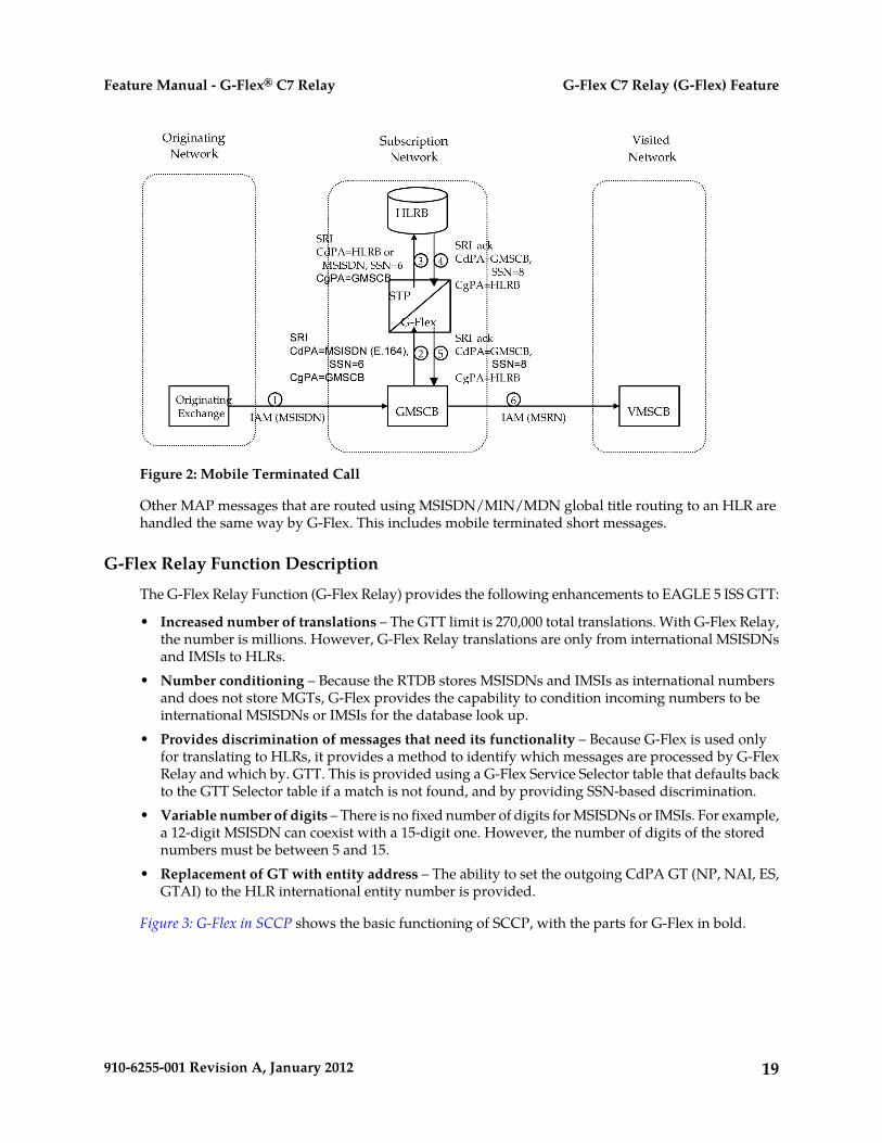
Figure 2: Mobile Terminated Call
Other MAP messages that are routed using MSISDN/MIN/MDN global title routing to an HLR arehandled the same way by G-Flex. This includes mobile terminated short messages.
G-Flex Relay Function Description
The G-Flex Relay Function (G-Flex Relay) provides the following enhancements to EAGLE 5 ISS GTT:
• Increased number of translations – The GTT limit is 270,000 total translations. With G-Flex Relay,the number is millions. However, G-Flex Relay translations are only from international MSISDNsand IMSIs to HLRs.
• Number conditioning – Because the RTDB stores MSISDNs and IMSIs as international numbersand does not store MGTs, G-Flex provides the capability to condition incoming numbers to beinternational MSISDNs or IMSIs for the database look up.
• Provides discrimination of messages that need its functionality – Because G-Flex is used onlyfor translating to HLRs, it provides a method to identify which messages are processed by G-FlexRelay and which by. GTT. This is provided using a G-Flex Service Selector table that defaults backto the GTT Selector table if a match is not found, and by providing SSN-based discrimination.
• Variable number of digits – There is no fixed number of digits for MSISDNs or IMSIs. For example,a 12-digit MSISDN can coexist with a 15-digit one. However, the number of digits of the storednumbers must be between 5 and 15.
• Replacement of GT with entity address – The ability to set the outgoing CdPA GT (NP, NAI, ES,GTAI) to the HLR international entity number is provided.
Figure 3: G-Flex in SCCP shows the basic functioning of SCCP, with the parts for G-Flex in bold.
19910-6255-001 Revision A, January 2012
G-Flex C7 Relay (G-Flex) FeatureFeature Manual - G-Flex® C7 Relay

Figure 3: G-Flex in SCCP
In order to keep the diagram simple, the only error conditions shown are the no-match cases for G-Flexand GTT selectors and translations. G-Flex has its own error handling for some cases that issues UIMsand peg measurements appropriately before letting the MSU fall through to GTT translation. Also,there are error conditions in GTT selection, GTT translation, and message transfer that are handledby GTT error handling.
G-Flex Relay is performed in the following stages.
1. The message arrives at EAGLE 5 ISS Route-on-GT. The EAGLE 5 ISS decodes the SCCP portionand uses the data to perform G-Flex selection based on the CdPA GT fields other than the ES andGTAI. The result of this selection provides two pieces of data, identification of the NP and NAI forG-Flex and a G-Flex Service Indicator. The Service Indicator is G-Flex if G-Flex Relay is required.If a G-Flex selector does not match the incoming GT fields, then GTT selection is attempted. It ispossible that G-Flex and GTT selectors will not match the incoming GT fields. In this case, GTTerror handling is used.
2. If stage 1 indicates that G-Flex Relay is required and if the message is not a UDTS-generated bythe EAGLE 5 ISS, the EAGLE 5 ISS performs SSN-based discrimination. If the G-Flex service stateis ONLINE, then step 3 is performed. Otherwise, G-Flex SCCP Service Re-Route is performed.
3. The conditioned number is looked up in the RTDB.4. If the number is found, the translation data for the number is used to alter and route the message.5. If G-Flex Relay is not required, or the number is not found in the RTDB, the set of GTT translations
is used for translation.
20910-6255-001 Revision A, January 2012
G-Flex C7 Relay (G-Flex) FeatureFeature Manual - G-Flex® C7 Relay
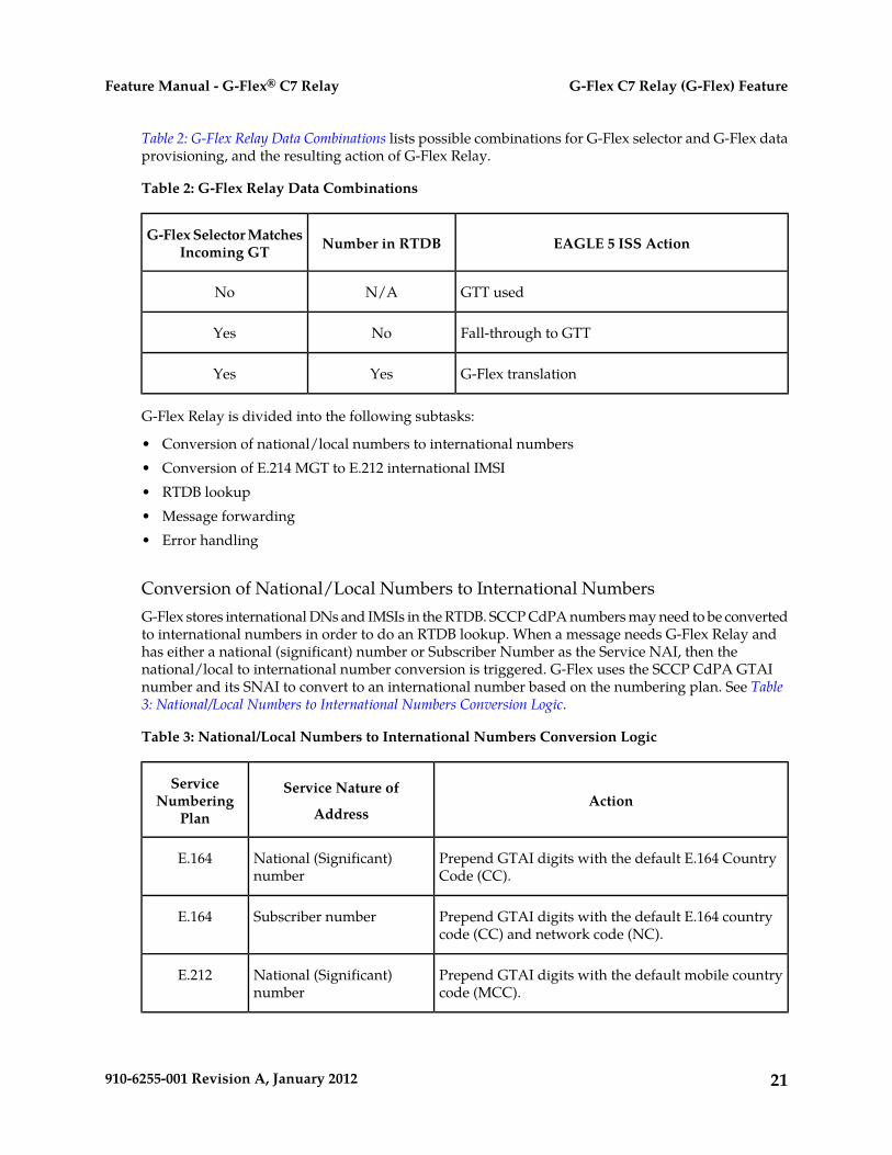
Table 2: G-Flex Relay Data Combinations lists possible combinations for G-Flex selector and G-Flex dataprovisioning, and the resulting action of G-Flex Relay.
Table 2: G-Flex Relay Data Combinations
EAGLE 5 ISS ActionNumber in RTDBG-Flex Selector MatchesIncoming GT
GTT usedN/ANo
Fall-through to GTTNoYes
G-Flex translationYesYes
G-Flex Relay is divided into the following subtasks:
• Conversion of national/local numbers to international numbers• Conversion of E.214 MGT to E.212 international IMSI• RTDB lookup• Message forwarding• Error handling
Conversion of National/Local Numbers to International NumbersG-Flex stores international DNs and IMSIs in the RTDB. SCCP CdPA numbers may need to be convertedto international numbers in order to do an RTDB lookup. When a message needs G-Flex Relay andhas either a national (significant) number or Subscriber Number as the Service NAI, then thenational/local to international number conversion is triggered. G-Flex uses the SCCP CdPA GTAInumber and its SNAI to convert to an international number based on the numbering plan. See Table3: National/Local Numbers to International Numbers Conversion Logic.
Table 3: National/Local Numbers to International Numbers Conversion Logic
ActionService Nature of
Address
ServiceNumbering
Plan
Prepend GTAI digits with the default E.164 CountryCode (CC).
National (Significant)number
E.164
Prepend GTAI digits with the default E.164 countrycode (CC) and network code (NC).
Subscriber numberE.164
Prepend GTAI digits with the default mobile countrycode (MCC).
National (Significant)number
E.212
21910-6255-001 Revision A, January 2012
G-Flex C7 Relay (G-Flex) FeatureFeature Manual - G-Flex® C7 Relay

ActionService Nature of
Address
ServiceNumbering
Plan
Prepend GTAI digits with the default Mobile CountryCode (MCC) and Mobile Network Code (MNC).
Subscriber numberE.212
Prepend GTAI digits with the default E.164 CountryCode (CC).
National (Significant)number
E.214
Prepend GTAI digits with the default E.164 CountryCode (CC) and Network Code (NC).
Subscriber numberE.214
Assume the default to be E.164 International numberN/AOther
Notes:
• If any of the default CC, NC, MCC, or MNC are required for conversion and are not provisionedin the database, G-Flex Relay issues a UIM and falls through to GTT.
• If the converted number is fewer than five digits, G-Flex Relay falls through and performs GTT onthe message. G-Flex Relay issues a UIM when a converted number is fewer than five digits.
• If the converted number is more than 15 digits, then G-Flex Relay issues a UIM when the numberexceeds 15 digits and falls through to GTT.
• G-Flex Relay uses the conditioned number for database lookup purposes only and does not modifythe CdPA GTAI in the message unless rcgta=yes or ccgt=yes.
• For the G-Flex selector-specified service numbering plan (IMSI, DN, or MGT), the numbering planin the incoming message is replaced with the G-Flex Selector service numbering plan (E.164, E.212,or E.214, respectively). This is for RTDB lookup purposes only.
Conversion of E.214 MGT to E.212 IMSIBecause the RTDB does not store MGTs, the messages with E.214 MGT in the CdPA GTAI are convertedto an E.212 International IMSI in order to perform the RTDB lookup. G-Flex maintains a logicalMGT2IMSI conversion table to perform this conversion. The MGT2IMSI conversion table contains upto ten entries of E.164 part (CC + NC digits) and its corresponding E.212 part (MCC + MNC). If aG-Flex message has E.214 as the CdPA numbering plan, G-Flex Relay performs the following steps toderive the E.212 International IMSI:
1. G-Flex Relay uses MGT as the key and does a lookup in the MGT2IMSI conversion table to find amatch on E.164 part (CC + NC digits).
2. If a match is found, G-Flex Relay replaces the matched digits of the MGT with the correspondingE.212 part (MCC + MNC digits). If a match is not found, a UIM is issued and the G-Flex Relay fallsthrough to GTT.
3. G-Flex Relay uses this complete E.212 International IMSI number to do the RTDB lookup.
Note: If the IMSI for a particular country/network is the complete 15 digits and the E.164 CC + NCfor that country is more than five digits, the MGT generated could contain a truncated MSIN. This is
22910-6255-001 Revision A, January 2012
G-Flex C7 Relay (G-Flex) FeatureFeature Manual - G-Flex® C7 Relay

possible because the converted MGT is more than 15 digits and the maximum number of digits allowedin the MGT is 15 digits. (Refer to E.214 for more details on conversion.) Under these circumstances,the MGT is truncated at 15 digits. Therefore, the MGT-to-IMSI reconversion would not regenerate acomplete IMSI and would lead to incorrect results and errors.
RTDB LookupG-Flex Relay performs the RTDB lookup using either the complete international DN or IMSI. If theDN or IMSI number is found in the RTDB and it has an HLR translation, then G-Flex Relay extractsthe HLR translation data and generates a forwarding message. G-Flex Relay falls through and performsGTT for the following error cases:
• The DN number is not present in the database.• The IMSI number is not present in the database.
The preceding error cases do not generate any UIM or UAM, but fall through to GTT processing.
If the RTDB lookup is for GTI=2 and is an even number of digits ending in 0, then G-Flex performs aless than or equal to lookup for the odd number of digits (digit length minus 1). If a match is found,G-Flex saves the record and record index.
G-Flex then tries to continue to find an exact match on the even number of digits. If the exact matchis found in the RTDB, then the HLR translation data corresponding to the even number of digits recordis used. Otherwise the HLR translation data corresponding to the found odd number of digits recordis used. If the even and odd translation is not found, then the G-Flex Relay falls through and performsGTT.
The important issue is that the less than or equal to search re-enters the search where the comparisonleft off. This minimizes any impact on performance for this special case.
Message Forwarding
GFRF Forwarding Message: MTP Portion
G-Flex modifies the MTP routing label to include the HLR PC as the DPC and the EAGLE 5 ISS truePC as the OPC. G-Flex modifies the MTP Level 2 length based on the size of the forwarding message.Table 4: G-Flex Relay Forwarding Message: MTP Portion lists the fields modified by G-Flex Relay.
Table 4: G-Flex Relay Forwarding Message: MTP Portion
ValuesFields
Number of octets in response MSU starting from MTP3 SIO field. Ifnumber of octets is greater than 63, Level 2 length is set to 63
MTP Level 2 length
Point code obtained from the HLR GT information in RTDBMTP Level 3 DPC
EAGLE 5 ISS true PCMTP Level 3 OPC
23910-6255-001 Revision A, January 2012
G-Flex C7 Relay (G-Flex) FeatureFeature Manual - G-Flex® C7 Relay
G-Flex Relay Forwarding Message: SCCP Portion
The following functions are performed for the SCCP portion of the message:
Replacing the CdPA GTAI digits with the HLR entity number
When an MSISDN or IMSI number is found in the RTDB and the Replace GT flag is set for this entry,G-Flex Relay replaces the CdPA GTAI digits with the provisioned HLR entity number. G-Flex alsomodifies the numbering plan (E.164), nature of address (international), and encoding scheme to matchthe HLR entity number.
G-Flex Relay does not replace the Global Title Indicator format (GTI) element of the GT.
Replacing of SSN in the CdPA
When the HLR translation data includes a SSN, G-Flex Relay replaces the SSN in the called partyaddress of the message with the new SSN. If the SSN is not present in the incoming message, thenG-Flex Relay updates the Subsystem Number Indicator and includes the new SSN in the Called PartyAddress of the message before it forwards the message to the next node.
Inclusion of OPC in the CgPA
When the routing indicator of the calling party address is set to Route-on-SSN, and no SPC is presentin it, the OPC from the received message is taken and inserted into the CgPA before the message isforwarded to the next node.
Deleting the CdPA GT Digits
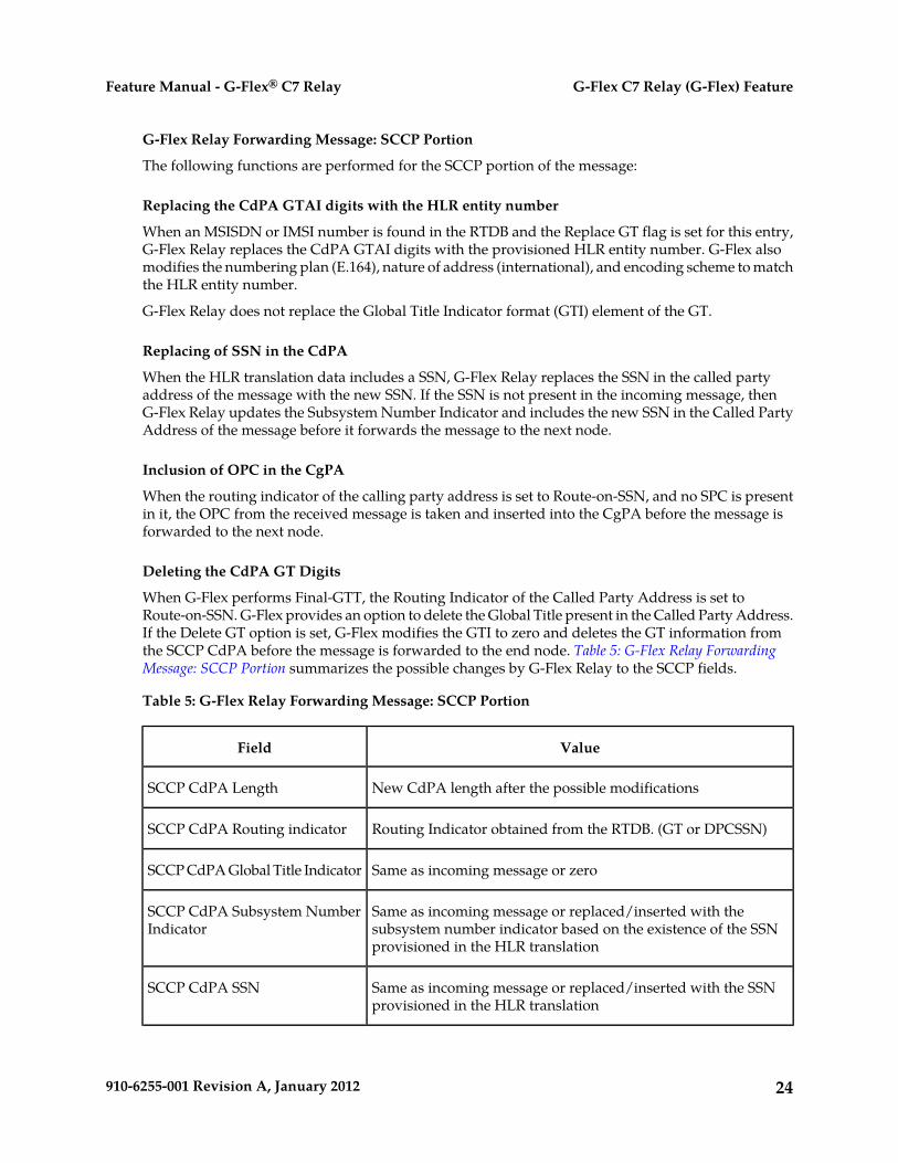
When G-Flex performs Final-GTT, the Routing Indicator of the Called Party Address is set toRoute-on-SSN. G-Flex provides an option to delete the Global Title present in the Called Party Address.If the Delete GT option is set, G-Flex modifies the GTI to zero and deletes the GT information fromthe SCCP CdPA before the message is forwarded to the end node. Table 5: G-Flex Relay ForwardingMessage: SCCP Portion summarizes the possible changes by G-Flex Relay to the SCCP fields.
Table 5: G-Flex Relay Forwarding Message: SCCP Portion
ValueField
New CdPA length after the possible modificationsSCCP CdPA Length
Routing Indicator obtained from the RTDB. (GT or DPCSSN)SCCP CdPA Routing indicator
Same as incoming message or zeroSCCP CdPA Global Title Indicator
Same as incoming message or replaced/inserted with thesubsystem number indicator based on the existence of the SSNprovisioned in the HLR translation
SCCP CdPA Subsystem NumberIndicator
Same as incoming message or replaced/inserted with the SSNprovisioned in the HLR translation
SCCP CdPA SSN
24910-6255-001 Revision A, January 2012
G-Flex C7 Relay (G-Flex) FeatureFeature Manual - G-Flex® C7 Relay

ValueField
Same as incoming message or replaced or deleted with HLR entityaddress provisioned in the RTDB
SCCP CdPA GT
New CgPA length after the possible modificationsSCCP CgPA Length
Same as incoming message or if CgPA RI is Route-on-SSN andPCI is not 1, then set PCI to 1
SCCP CgPA Point Code Indicator
If the CgPA RI is Route-on-SSN and no point code is present inthe CgPA SPC, then the OPC is included as the SPC (SecondaryPoint Code)
SCCP CgPA SPC
Same as incoming message or replaced/inserted with theSubsystem Number indicator based on the existence of the SSNprovisioned in the HLR translation
SCCP CdPA Subsystem NumberIndicator
Error Handling
The purpose of the Error Handling is to discard or return messages that encounter routing and databasefailures and cannot be delivered to the HLR. When G-Flex Relay is unable to transfer a message andReturn on Error is set, then G-Flex Relay follows the same error handling procedures used by GTT.The DATA field of the UDT message and the reason cause for return are included in UDTS message.
G-Flex Relay follows the same error handling procedures as GTT for the following error cases:
• Routing failures• Network congestion
Forwarding message after replace GT and/or Insertion of OPC or SSN is greater than the CCS7 messagelimit (272 bytes).
An exception to GTT error handling is when the G-Flex Relay RTDB entry cannot be found. In thiscase, it is not considered an error and the G-Flex Relay capability will forward the message to GTTprocessing.
MTP-Routed SCCP Message Processing
An MTP-routed message is a “through-switched” message that is not generated by or destined to theEAGLE 5 ISS (neither the MTP OPC nor DPC is the EAGLE 5 ISS true point code or capability pointcode). An MTP-routed message is routed to the destination designated by the DPC of the MTP3 routinglabel.
Typically, MSUs that receive service on a Service Module card require the message to be GT-routedto the EAGLE 5 ISS, so that GTT service selector-based discrimination can be applied to the messageto select a specific service (such as GFLEX).
When the MTP Routed Messages for SCCP Applications (MTP Msgs for SCCP Apps) feature is on, itforwards all incoming MTP-routed SCCP messages (SI=3 in the message) from LIM cards to Service
25910-6255-001 Revision A, January 2012
G-Flex C7 Relay (G-Flex) FeatureFeature Manual - G-Flex® C7 Relay
Module cards for processing. The feature is available system-wide and can be enabled and turned onwhen the GTT feature is turned on.
If the MTP-routed message arrives with the CdPA RI=GT or RI=SSN, and the CdPA GTI=2 (ANSI)or GTI=2 or 4 (ITU), service selection is performed.
• If the GFLEX service is selected, then the message is handled by the GFLEX service and the messageprocessing is the same as that used for GT-routed messages.
• If the service selection does not find a match, or if the service is OFFLINE, then the message isMTP-routed.
Service re-route is not performed on MTP-routed messages.
The GFLEX service is not supported for MTP-routed messages that contain SCCP CdPA GTI=0.
G-Flex Configuration Options
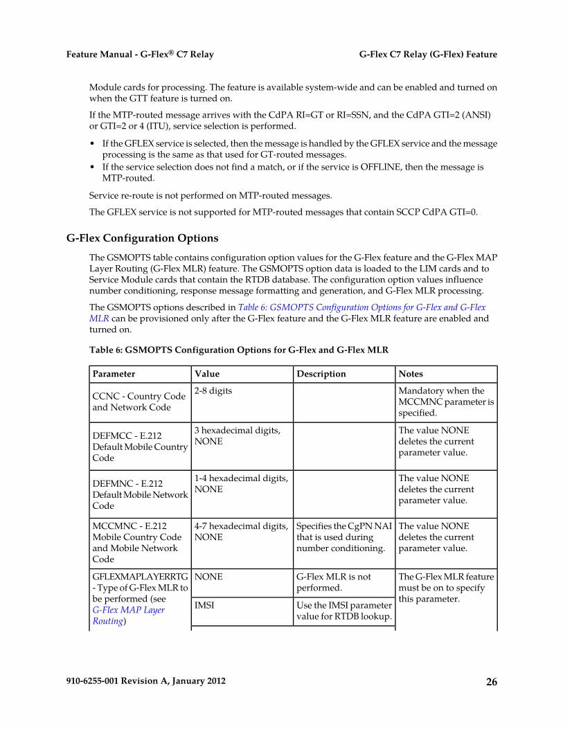
The GSMOPTS table contains configuration option values for the G-Flex feature and the G-Flex MAPLayer Routing (G-Flex MLR) feature. The GSMOPTS option data is loaded to the LIM cards and toService Module cards that contain the RTDB database. The configuration option values influencenumber conditioning, response message formatting and generation, and G-Flex MLR processing.
The GSMOPTS options described in Table 6: GSMOPTS Configuration Options for G-Flex and G-FlexMLR can be provisioned only after the G-Flex feature and the G-Flex MLR feature are enabled andturned on.
Table 6: GSMOPTS Configuration Options for G-Flex and G-Flex MLR
NotesDescriptionValueParameter
Mandatory when theMCCMNC parameter isspecified.
2-8 digitsCCNC - Country Codeand Network Code
The value NONEdeletes the currentparameter value.
3 hexadecimal digits,NONEDEFMCC - E.212
Default Mobile CountryCode
The value NONEdeletes the currentparameter value.
1-4 hexadecimal digits,NONEDEFMNC - E.212
Default Mobile NetworkCode
The value NONEdeletes the currentparameter value.
Specifies the CgPN NAIthat is used duringnumber conditioning.
4-7 hexadecimal digits,NONE
MCCMNC - E.212Mobile Country Codeand Mobile NetworkCode
The G-Flex MLR featuremust be on to specifythis parameter.
G-Flex MLR is notperformed.
NONEGFLEXMAPLAYERRTG- Type of G-Flex MLR tobe performed (seeG-Flex MAP LayerRouting)
Use the IMSI parametervalue for RTDB lookup.
IMSI
26910-6255-001 Revision A, January 2012
G-Flex C7 Relay (G-Flex) FeatureFeature Manual - G-Flex® C7 Relay

NotesDescriptionValueParameter
Use the MSISDNparameter value forRTDB lookup.
MSISDN
Use the IMSI or theMSISDN parameter
ALL
value for RTDB lookup,based on the messageoperation code.
The G-Flex MLR featuremust be on to specifythese parameters.
Perform (ON) or do notperform (OFF) G-FlexMLR processing for theregisterSS operation.
REGSSMAPLYRRTGON
MAPLYRRTGOFF -Perform (ON) or do notperform (OFF) G-Flex
Perform (ON) or do notperform (OFF) G-Flex
ACTSSMLR for each specifiedoperation or alloperations (see G-FlexMAP Layer Routing)
MLR processing for theactivateSS operation.
Perform (ON) or do notperform (OFF) G-Flex
DACTSS
MLR processing for thedeactivateSS operation.
Perform (ON) or do notperform (OFF) G-Flex
INTROSS
MLR processing for theinterrogateSS operation.
Perform (ON) or do notperform (OFF) G-Flex
AUTHFAILRPT
MLR processing for theauthenticationFailureReportoperation.
Perform (ON) or do notperform (OFF) G-Flex
RSTDATA
MLR processing for therestoreData operation.
Perform (ON) or do notperform (OFF) G-Flex
PROCUNSTRQT
MLR processing for theprocessUnstructuredSS-Requestoperation.
Perform (ON) or do notperform (OFF) G-Flex
RDYFORSM
MLR processing for thereadyForSM operation.
27910-6255-001 Revision A, January 2012
G-Flex C7 Relay (G-Flex) FeatureFeature Manual - G-Flex® C7 Relay
NotesDescriptionValueParameter
Perform (ON) or do notperform (OFF) G-Flex
PURGMOBSS
MLR processing for thepurgeSS operation.
Perform (ON) or do notperform (OFF) G-Flex
SRILOC
MLR processing for thesendRoutingInfoForLCSoperation.
Perform (ON) or do notperform (OFF) G-Flex
ALL
MLR processing for all10 of the listedoperations.
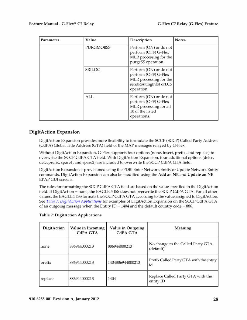
DigitAction Expansion
DigitAction Expansion provides more flexibility to formulate the SCCP (SCCP) Called Party Address(CdPA) Global Title Address (GTA) field of the MAP messages relayed by G-Flex.
Without DigitAction Expansion, G-Flex supports four options (none, insert, prefix, and replace) tooverwrite the SCCP CdPA GTA field. With DigitAction Expansion, four additional options (delcc,delccprefix, spare1, and spare2) are included to overwrite the SCCP CdPA GTA field.
DigitAction Expansion is provisioned using the PDBI Enter Network Entity or Update Network Entitycommands. DigitAction Expansion can also be modified using the Add an NE and Update an NEEPAP GUI screens.
The rules for formatting the SCCP CdPA GTA field are based on the value specified in the DigitActionfield. If DigitAction = none, the EAGLE 5 ISS does not overwrite the SCCP CdPA GTA. For all othervalues, the EAGLE 5 ISS formats the SCCP CdPA GTA according to the value assigned to DigitAction.See Table 7: DigitAction Applications for examples of DigitAction Expansion on the SCCP CdPA GTAof an outgoing message when the Entity ID = 1404 and the default country code = 886.
Table 7: DigitAction Applications
MeaningValue in OutgoingCdPA GTA
Value in IncomingCdPA GTA
DigitAction
No change to the Called Party GTA(default)886944000213886944000213none
Prefix Called Party GTA with the entityid1404886944000213886944000213prefix
Replace Called Party GTA with theentity ID1404886944000213replace
28910-6255-001 Revision A, January 2012
G-Flex C7 Relay (G-Flex) FeatureFeature Manual - G-Flex® C7 Relay

MeaningValue in OutgoingCdPA GTA
Value in IncomingCdPA GTA
DigitAction
Insert entity ID after country code. (CC+ Entity Id + NDC + SN)8861404944000213886944000213insert
Delete country code and add prefix1404944000213886944000213delccprefix (No action is taken if country code is
not present.)
Delete country code944000213886944000213delcc
No change to the Called Party GTA(default)treated as none886944000213spare1
No change to the Called Party GTA(default)treated as none886944000213spare2
Digit Action DELCCPREFIX
The Digit Action to delete country code if present and prefix database entity feature allows theDELCCPREFIX Digit Action to be applied to the Called Party Global Title Address (CdPA GTA) whenthe GTA has a National format, as well as when the GTA has an International format. TheDELCCPREFIX option in the SCCPOPTS table specifies how the DELCCPREFIX digit action is appliedto a Called Party Global Title Address (CdPA GTA).
• When the SCCPOPTS:DELCCPREFIX option is set to PFXWCC, the DELCCPREFIX digit action isapplied to the CdPA GTA only when the address has a International format. The Country Code isdeleted and the GTA is prefixed with the Entity ID.
• When the SCCPOPTS:DELCCPREFIX option is set to PFX4ALL, the DELCCPREFIX digit action isapplied to the CdPA GTA in all cases. For an International format, the Country Code is deletedand the GTA is prefixed with the Entity ID. For a National format, the GTA is prefixed with theEntity ID.
The chg-sccpopts command is used to specify the delccprefix parameter value to configure theDELCCPREFIX Digit Action functionality.
G-Flex SCCP Service Re-Route Capability
G-Flex SCCP Service Re-Route Capability provides the ability to re-route the traffic from one EAGLE5 ISS to other G-Flex nodes within an operator's network, and inform the originating nodes to re-routethe G-Flex service related traffic to other G-Flex service nodes. The following functions are used toprovide G-Flex re-routing capability:
• Service Capability Point Codes• Service State• Service Re-routing (using alternate point codes and a configuration option)
Service State
29910-6255-001 Revision A, January 2012
G-Flex C7 Relay (G-Flex) FeatureFeature Manual - G-Flex® C7 Relay
G-Flex SCCP Service Re-Route Capability provides an option to change the state of the G-Flex serviceto OFFLINE or ONLINE. The service state is persistent. Booting the OAM or all of he Service Modulecards would not change the service state. The service state must be manually changed .
• The G-Flex service state defaults to OFFLINE when the G-Flex feature is turned on in the system.The service must be set to ONLINE and at least one Service Module card must be IS-NR(In-Service-Normal) before G-Flex processing occurs in the system.
• The G-Flex service can be taken OFFLINE at any time, such as when the databases are incoherentor Service Module cards need to be reloaded for some reason. Taking the service OFFLINE causesprocessing of G-Flex traffic to stop and allows a controlled re-routing procedure to be performed.A Critical UAM is generated as a warning that the G-Flex service is disabled because it has beentaken OFFLINE.
Service Re-routing
Service re-routing is optional and does not affect normal G-Flex processing.
Service re-routing can be enabled by using the chg-sccp-serv command to define a list of alternatePCs or to set the GTT option to YES. Re-routing is initiated by taking a service OFFLINE.
• If alternate PCs are provisioned any messages destined to that service would be re-routed toavailable alternate PCs defined for that service. Up to 7 alternate point codes per domain can bedefined. ANSI, ITU-I, ITU-N, ITU-I spare, ITU-N spare, and ITU-N24 domains are supported. Anentire set of alternate point codes is called a Re-route set. Intermediate GTT loadsharing rules applyto the Alternate PC Re-route set.
• The GTT option is used if alternate PCs are not provisioned or none of them are available. If theGTT option value is YES (the default), then messages destined to that service would fall throughto GTT as part of the re-routing procedure.
Service Capability Point Codes
One or more G-Flex Capability Point Codes (CPC) can be provisioned when the G-Flex feature is on.The Capability Point Code is used to distinguish G-Flex messages from other types of messages, sothat the G-Flex service OFFLINE state can be reported by sending response method TFPs to G-Flexnodes. (Response method TFx messages are not generated if CPCs are not used.)
The service CPCs aid the adjacent nodes in knowing about a service outage. When a service is takenOFFLINE and capability point codes are defined for the service, the following actions occur for alltraffic destined to the service node:
• A response method TFP message is generated to the adjacent node about the service CPC.• The TFP response to the adjacent node causes the traffic-originating nodes to stop sending service
traffic to this node.• All service traffic coming into this node is sent to the alternate service nodes.• Adjacent nodes initiate route-set-test procedures after receipt of the TFP.
If the messages are destined to the EAGLE 5 ISS true point code, then TFP messages are not generatedwhen a service is OFFLINE, and the originator would not be aware of the outage.
After the service is back ONLINE in the EAGLE 5 ISS, a TFA message is sent to the traffic-adjacentnodes in response to route-set-test message. The traffic-originating nodes then start sending servicetraffic to this node.
30910-6255-001 Revision A, January 2012
G-Flex C7 Relay (G-Flex) FeatureFeature Manual - G-Flex® C7 Relay

G-Flex Re-Route Message HandlingTable 8: G-Flex SCCP Re-Route Message Handling Summary shows the actions that the EAGLE 5 ISS takeswith the G-Flex service is OFFLINE, a message requiring G-Flex service arrives at the affected node,and Service Module cards are available.
Table 8: G-Flex SCCP Re-Route Message Handling Summary
NetworkManagement
MessageHandling
GTT to bePerformed as FallThrough
Alternate PCDefined andAvailable
DPC
TFP concerningCPC
Rer-oute toalternate PC basedon Relative Cost(RC)
N/AYesG-Flex CPC
TFP concerningCPC
Fall through to andperform GTT
YesNo (Defined, andprohibited orcongested)
G-Flex CPC
TFP concerningCPC
Generate UDTS(Return Cause =Network Failure)
NoNo (Defined, andprohibited orcongested)
G-Flex CPC
TFP concerningCPC
Fall through to andperform GTT
YesNot DefinedG-Flex CPC
TFP concerningCPC
Generate UDTS(Return Cause =No xlation for thisaddr)
NoNot DefinedG-Flex CPC
NoneRe-route toalternate PC based
N/AYesTrue or SecondaryPC or non-G-FlexCPC on Relative Cost
(RC)
NoneGenerate UDTS(Return Cause =Network Failure)
NoNo (Defined, andprohibited orcongested)
True or SecondaryPC or non-G-FlexCPC
NoneFall through to andperform GTT
YesNo (Defined, andprohibited orcongested)
True or SecondaryPC or non-G-FlexCPC
NoneFall through to andperform GTT
YesNot DefinedTrue or SecondaryPC or non-G-FlexCPC
NoneGenerate UDTS(Return Cause =
NoNot DefinedTrue or SecondaryPC or non-G-FlexCPC No xlation for this
addr)
31910-6255-001 Revision A, January 2012
G-Flex C7 Relay (G-Flex) FeatureFeature Manual - G-Flex® C7 Relay
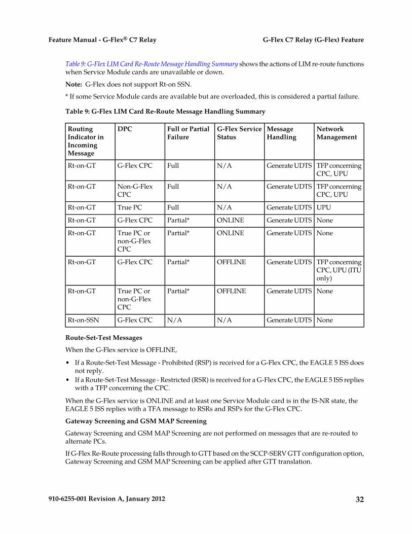
Table 9: G-Flex LIM Card Re-Route Message Handling Summary shows the actions of LIM re-route functionswhen Service Module cards are unavailable or down.
Note: G-Flex does not support Rt-on SSN.
* If some Service Module cards are available but are overloaded, this is considered a partial failure.
Table 9: G-Flex LIM Card Re-Route Message Handling Summary
NetworkManagement
MessageHandling
G-Flex ServiceStatus
Full or PartialFailure
DPCRoutingIndicator inIncomingMessage
TFP concerningCPC, UPU
Generate UDTSN/AFullG-Flex CPCRt-on-GT
TFP concerningCPC, UPU
Generate UDTSN/AFullNon-G-FlexCPC
Rt-on-GT
UPUGenerate UDTSN/AFullTrue PCRt-on-GT
NoneGenerate UDTSONLINEPartial*G-Flex CPCRt-on-GT
NoneGenerate UDTSONLINEPartial*True PC ornon-G-FlexCPC
Rt-on-GT
TFP concerningCPC, UPU (ITUonly)
Generate UDTSOFFLINEPartial*G-Flex CPCRt-on-GT
NoneGenerate UDTSOFFLINEPartial*True PC ornon-G-FlexCPC
Rt-on-GT
NoneGenerate UDTSN/AN/AG-Flex CPCRt-on-SSN
Route-Set-Test Messages
When the G-Flex service is OFFLINE,
• If a Route-Set-Test Message - Prohibited (RSP) is received for a G-Flex CPC, the EAGLE 5 ISS doesnot reply.
• If a Route-Set-Test Message - Restricted (RSR) is received for a G-Flex CPC, the EAGLE 5 ISS replieswith a TFP concerning the CPC.
When the G-Flex service is ONLINE and at least one Service Module card is in the IS-NR state, theEAGLE 5 ISS replies with a TFA message to RSRs and RSPs for the G-Flex CPC.
Gateway Screening and GSM MAP Screening
Gateway Screening and GSM MAP Screening are not performed on messages that are re-routed toalternate PCs.
If G-Flex Re-Route processing falls through to GTT based on the SCCP-SERV GTT configuration option,Gateway Screening and GSM MAP Screening can be applied after GTT translation.
32910-6255-001 Revision A, January 2012
G-Flex C7 Relay (G-Flex) FeatureFeature Manual - G-Flex® C7 Relay
G-Flex in an ANSI Environment
The Support ANSI G-Flex at 1700 TPS per DSM function increases the transaction capacity of theG-Flex feature running on a DSM card from 850 TPS to 1700 TPS for ANSI systems. (ITU systemsoperate at 850 TPS per DSM.)
The STPOPTS ANSIGFLEX option (chg-stpopts:ansigflex=yes command) allows DSM cardsto operate at 1700 TPS when the G-Flex feature is ON. The default for the ANSIGFLEX system optionis NO (disabled).
The G-Flex feature must be on, no other EPAP-related features can be on, and no ITU service selectorscan be provisioned, before the ANSIGFLEX system option can be set to YES.
The ANSIGFLEX system option can be set to NO after it has been set to YES. DSM card TPS grantingis reduced to 850 TPS when the option setting is NO. A notification to the user concerning the reductionin SCCP capacity is generated.
Although a warning message is provided when the ANSIGFLEX option is set to NO, the user mustperform system checks manually to ensure that SCCP system capacity will be sufficient after theANSIGFLEX option is set to NO. If the user does not perform these capacity checks, the system maydiscard SCCP messages (TVG grant failures).
The SCCP capacity is reported in the rept-stat-sccp:mode=perf command output; the commandlists the performance of all DSM cards, including message rates for TVG. The TVG capacities that arereported in the rept-stat-sccp command take into account the ANSIGFLEX system option.
G-Flex as a "Stand-Alone" Node
G-Flex can be deployed two ways (the G-Flex processing is the same for both ways, as described inthis manual):
• As an integrated part of the STP (Signal Transfer Point)• As a "stand-alone" node
Destinations, routes, and point codes can be configured so that one STP of a mated EAGLE 5 ISSpair performs only G-Flex processing, while the other STP performs all of the STP other functions.
Assumptions/Limitations
The following assumptions and limitations apply.
1. The EAGLE 5 ISS does not perform any conversion in the SCCP portion of the message to supportmessage routing across the domain boundary (ANSI to ITU and visa versa).
2. The EAGLE 5 ISS supports message routing across network boundaries (ITU-N to ITU-I and visaversa). However, GTT and Enhanced GTT (EGTT) do not modify the National Indicator bit in theCdPA Address Indicator (AI) or convert the CdPA PC (Point Code) to match the network type.
3. For messages with E.214 numbers in the SCCP CdPA, a simple conversion can form an E.212number. The E.212 number formed in this way is the full IMSI of the subscriber, that is, it is assumedthat no truncation occurs when the E.214 number is originally formed from the E.212 number. Suchtruncation is allowed by the E.214 recommendation.
4. G-Flex allows for up to eight MSISDN numbers per subscriber (that is, per IMSI) to be related. Itis assumed that operators do not need to support more than eight MSISDN numbers per subscriber.
33910-6255-001 Revision A, January 2012
G-Flex C7 Relay (G-Flex) FeatureFeature Manual - G-Flex® C7 Relay
5. No overload controls are required beyond the existing EAGLE 5 ISS lower level mechanisms (forexample, for MTP congestion)
6. Using combinations of the GTT selectors GTI (Global Title Indicator), TT (Translation Type), NP(Number Portability), and NAI as triggers for G-Flex processing plus SSN discrimination providethe ability to limit G-Flex processing to only the messages for which it is appropriate.
7. G-Flex C7 Relay supports message routing to a single network node for a particular subscriber.For example, an individual subscriber cannot have some messages routed to his HLR and othermessages routed to a separate AuC. In this example, G-Flex does not support the AuC beingcollocated with the HLR.
8. For performance estimates, EAGLE 5 ISS-generated UDTS messages will count as two processedmessages.
Hardware Requirements
EPAP-related features that perform an RTDB lookup require Service Module cards (DSM cards,E5-SM4G cards, or E5-SM8G-B cards) running the VSCCP application. The EAGLE 5 ISS can beequipped with up to 32 (31+1) Service Module cards.
Features that do not perform an RTDB lookup require Service Module cards only for GTT processingthat might be performed for the feature. These features can coexist in systems with EPAP, but do notrequire an EPAP connection.
MPS/EPAP Platform
Tekelec provides the Multi-Purpose Server (MPS) platform as a subsystem of the EAGLE 5 ISS. TheMPS provides support for EPAP-related features that perform Real Time Database (RTDB) lookups.
The MPS is composed of hardware and software components that interact to create a secure andreliable platform. For details about the MPS hardware, refer to Tekelec 1200 Application Server HardwareManual. The MPS provides the means of connecting the customer provisioning application with theEAGLE 5 ISS and accepts the customer number portability data, while accommodating numbers ofvarying lengths.
The EAGLE Provisioning Application Processor (EPAP) is software that runs on the MPS hardwareplatform. It collects and organizes customer provisioning data, and forwards the data to the EAGLE5 ISS Service Module cards. Figure 4: MPS/EPAP Platform Architecture shows the overall systemarchitecture from customer provisioning through the MPS subsystem to the EAGLE 5 ISS ServiceModule card databases.
In this manual, Service Module card refers to a DSM card, an E5-SM4G card, or an E5-SM8G-B cardunless a specific card is required. For more information about the supported cards, refer to EAGLE 5ISS Hardware Manual.
34910-6255-001 Revision A, January 2012
G-Flex C7 Relay (G-Flex) FeatureFeature Manual - G-Flex® C7 Relay

Figure 4: MPS/EPAP Platform Architecture
Design Overview and System Layout
Figure 4: MPS/EPAP Platform Architecture identifies the tasks, databases and interfaces which constitutethe overall system architecture. The system consists of two mated MPS servers. Each MPS containstwo EPAP platforms - EPAP A and EPAP B with each containing a Real Time Database (RTDB) ,Provisioning Database (PDB), servers, optical media, modems, and network switches when using aT1200 AS system. Each MPS and its associated EPAPs are an EPAP system; the EPAP system and themated EAGLE 5 ISS are the mated EPAP system. Each EPAP system is a T1200 AS system with a totalof four Ethernet interfaces: one from each EPAP to the 100BASE-T Ethernet and one from each EPAPto either a 10BASE-T or a 100BASE-T Ethernet. See Table 10: Service Module Card Provisioning and ReloadSettings for the link speed.
On the EAGLE 5 ISS, a set of Service Module cards, which hold the RTDB, is part of the STP. Twohigh-speed Ethernet links connect the Service Module cards and the EPAPs. One of the links is a100BASE-T Ethernet bus, and the other is either a 10BASE-T or a 100BASE-T Ethernet bus. See Table10: Service Module Card Provisioning and Reload Settings for the link speed.
35910-6255-001 Revision A, January 2012
G-Flex C7 Relay (G-Flex) FeatureFeature Manual - G-Flex® C7 Relay
The RTDB is provisioned and maintained through the EPAPs. EPAP A and EPAP B act as the activeEPAP and the standby EPAP. One link serves as the active link, and the other link as the standby link.Only one EPAP and one link are active at a time. The database is provisioned through the active linkby the active EPAP; the other EPAP provides redundancy.
If the active EPAP fails, the standby EPAP takes over the role of active EPAP and continues to provisionthe subscriber database. If the active link fails, the active EPAP switches to the standby link to continueprovisioning the Service Module cards. The two Ethernet links are part of the DSM network.
Another 100BASE-T Ethernet link exists between the EPAPs; that link is called the EPAP Sync Network.
The major modules on the EPAP are:
• Service Module card provisioning module• Maintenance module• RTDB module• PDB module
The Service Module card provisioning module is responsible for updating subscriber databases onthe EAGLE 5 ISS Service Module cards using the Reliable Multicast Transport Protocol (RMTP)multicast. The maintenance module is responsible for the proper functioning of the EPAP platform.The PDB module is responsible for preparing and maintaining the Real Time Database, which is thegolden copy of the subscriber database. The PDB module can run on one of the EPAPs of either matedEAGLE 5 ISS.
Functional Overview
The main function of the MPS/EPAP platform is to provision data from the customer network to theService Module cards on the EAGLE 5 ISS. Subscriber database records are continuously updatedfrom the customer network to the PDB. The PDB module communicates with the maintenance moduleand the RTDB task over a TCP/IP connection to provision the Service Module cards on the EAGLE 5ISS. The maintenance module is responsible for the overall stability and performance of the system.
The RTDB on the EPAP contains a coherent, current copy of the subscriber database. If the currentcopy of the RTDB on the Service Module cards becomes out-of-sync because of missed provisioningor card rebooting, the EPAP Service Module card provisioning module sends database informationthrough the provisioning link to the Service Module cards. The Service Module cards are reprovisionedwith current subscriber information.
EPAP/PDBA Overview
The EAGLE Provisioning Application Processor (EPAP) platform and the Provisioning DatabaseApplication (PDBA), coupled with the Provisioning Database Interface (PDBI) facilitate the userdatabase required for EAGLE 5 ISS EPAP-related features. The following functions are supported:
• Accept and store subscription data provisioned by the customer• Update and reload subscriber databases on the Service Module cards
The PDBA operates on the master Provisioning Database (PDB). The EPAP and PDBA are both installedon the MPS hardware platform.
The EPAP platform performs the following:
• Maintains an exact copy of the real time database (RTDB) on the EPAP
36910-6255-001 Revision A, January 2012
G-Flex C7 Relay (G-Flex) FeatureFeature Manual - G-Flex® C7 Relay

• Distributes the subscription database to the Service Module cards• Maintains a redundant copy of the RTDB database
The EPAP platform is a mated pair of processors (the upper processor, called EPAP A, and the lowerprocessor, EPAP B) contained in one frame.
During normal operation, information flows through the EPAP/PDBA software with no intervention.Subscription data is generated at one or more operations centers and is delivered to the PDBA througha TCP socket interface (PDBI). The PDBA software stores and replicates data on EPAP A on the matedEPAP system. The data is then transmitted by the EPAPs across a private network to the ServiceModule cards located in the EAGLE 5 ISS frame.
The primary interface to the PDBA consists of machine-to-machine messages. The interface is definedby Tekelec and is described in the Provisioning Database Interface Manual. Provisioning softwarecompatible with the EPAP socket interface can be created or updated using the interface described inthat manual.
Additionally, a direct user interface is provided on each EPAP to allow for configuration, maintenance,debugging, and platform operations. A direct user interface is also provided by the PDBA forconfiguration and database maintenance.
The MPS/EPAP is an open-systems platform and easily accommodates the required high provisioningrates. Compared to the traditional OAM platform, the persistent database and provisioning in an opensystems platform provides these benefits:
• Variety of hardware components and vendors• Availability of third party communication and database tools• Standard communication protocols• Availability of personnel with related experience
Each EPAP server maintains a copy of the Real Time Database (RTDB) in order to provision the EAGLE5 ISS Service Module cards. The EPAP server must comply with the hardware requirements in theTekelec 1200 Application Server Hardware Manual. Figure 4: MPS/EPAP Platform Architecture illustratesthe EPAP architecture contained in the MPS subsystem.
Each EPAP has a dedicated optical media drive. One EPAP per EAGLE 5 ISS platform has a modemcapable of supporting remote diagnostics, configuration, and maintenance. These remote operationsare performed through EPAP login sessions and are accessible across the customer network as wellas through a direct terminal connection to the EPAP using an RS232 connection. Refer to Tekelec 1200Application Server Hardware Manual for details about the hardware devices and network connections.
Subscriber Data Provisioning
Figure 5: Subscriber Data Provisioning Architecture (High Level) shows a high-level view of the subscriberdata provisioning architecture. Only those parts of the EAGLE 5 ISS platform that are relevant tosubscriber data provisioning are shown. This section defines requirements for the Provisioning DatabaseInterface (PDBI) between the EPAP and the operator's provisioning system (OPS). Provisioning clientsconnect to the EPAPs using the PDBI. This interface contains commands that allow all of theprovisioning and retrieval of subscription data. The PDBI is used for real-time provisioning of subscriberand network entity data only. Refer to Provisioning Database Interface Manual for more details.
37910-6255-001 Revision A, January 2012
G-Flex C7 Relay (G-Flex) FeatureFeature Manual - G-Flex® C7 Relay

Figure 5: Subscriber Data Provisioning Architecture (High Level)
A pair of active/standby EPAP servers provides the interface between the Real Time Database (RTDB)of the EAGLE 5 ISS Service Module cards and the OPS. EPAP A is equipped with both the PDB(Provisioning Database) and the RTDB, and EPAP B has only the RTDB. An EPAP with only the RTDBmust be updated by the EPAP that is equpped with the PDB.
For more information about the EPAP, refer to EPAP Administration Manual. For more informationabout the MPS hardware, refer to Tekelec 1200 Application Server Hardware Manual .
Distributed Administrative ArchitectureThis section describes, at a high level, the distributed administrative architecture for the EAGLE 5 ISS,including the EPAP.
Databases requiring high update and retrieval rates, such as the EPAP RTDB, are populated usingredundant Ethernet connections to Service Module cards from an EPAP MPS platform.
An EPAP consists of a combined Provisioning (MySQL) and Real Time Database (RTDB). TheProvisioning Database (PDB) responds to requests for updates by the active and standby RTDBs onboth mated EAGLE 5 ISSs. The active EPAP RTDB is responsible for initiating multi-cast updates ofchanged database records to the Service Module cards after the data has been committed to the EPAPdisks. Furthermore, the PDB may accept and commit more database updates while the RTDBs arecompleting their previous updates.
38910-6255-001 Revision A, January 2012
G-Flex C7 Relay (G-Flex) FeatureFeature Manual - G-Flex® C7 Relay

It is this overlapping of database updates, coupled with an RTDB transactional database engine andfast download time, that allows larger amounts of data at a time to be transferred from the PDB.Committing larger amounts of data at a time to the RTDB (versus a single update at a time) allowsfaster overall transaction rates to be achieved. The boundaries of the transaction rates become moreclosely related to cache size and disk cache flush time than the disk access time of a single update.Thus, successful completion of EPAP database updates only guarantees that the PDB has been updated,but it does not mean the RTDB has completed the update and sent the new subscription data to theService Module card.
The EPAP architecture contains a local provisioning terminal and a modem for remote access, as wellas other functions. A backup device can be used to back up or restore the provisioning database. Thelocal provisioning terminal is used to manually repair the standby EPAP RTDB or to turn the subscriberdatabase audit on or off. For additional information, refer to Tekelec 1200 Application Server HardwareManual and the EPAP Administration Manual.
EPAP (EAGLE Provisioning Application Processor)
As shown in Figure 4: MPS/EPAP Platform Architecture, a single MPS system contains two EAGLEProvisioning Application Processor (EPAP) servers. At any given time, only one EPAP activelycommunicates with the Service Module cards on the EAGLE 5 ISS. The other EPAP server is in standbymode. In addition, two MPS systems can be deployed in a mated pair configuration.
The primary purpose of the EPAP system is to maintain the Real Time Database ( RTDB) andProvisioning Database ( PDB), and to download copies of the RTDB to the Service Module cards.
The PDB on the active EPAP receives subscription data from the customer network through theProvisioning Database Interface ( PDBI), the external source of provisioning information. TheProvisioning Database Application( PDBA) continually updates the PDB of the active EPAP. The PDBuses MySQL database software. After an update is applied to the active PDB, the data is sent to theRTDBs on the active and standby EPAPs.
Both the active and standby EPAPs maintain copies of the RTDB. Periodically, the Service Modulecard polls the active EPAP RTDB for any new updates. The active EPAP downloads the updates tothe Service Module card which stores a resident copy of the RTDB.
A mated pair configuration has two mated MPS Systems, as shown in Figure 4: MPS/EPAP PlatformArchitecture. The PDB on the active EPAP automatically updates the PDB on the mate platform. ThePDB on the mate platform then updates RTDBs on its EPAPs, which in turn update the RTDBs on theassociated Service Module cards.
Provisioning of the EAGLE 5 ISS Service Module cards is performed through two interfaces using twodifferent sets of commands. Provisioning is accomplished by the STP updates from EAGLE 5 ISSterminals and by updates from the customer’s external provisioning system. This system of dualprovisioning is illustrated in Figure 6: Database Administrative Architecture.
39910-6255-001 Revision A, January 2012
G-Flex C7 Relay (G-Flex) FeatureFeature Manual - G-Flex® C7 Relay

Figure 6: Database Administrative Architecture
Service Module Cards
Up to 32 cards (31+1) Service Module cards can be provisioned with one or more EPAP-related featuresenabled and EPAP running on a T1200 AS.
EPAP-related features require that all Service Module cards contain 4 GB of memory. Figure 6: DatabaseAdministrative Architecture illustrates each Service Module card having two Ethernet links, the mainDSM network on the 100BASE-T link and the backup DSM network . See Table 10: Service Module CardProvisioning and Reload Settings for the link speed. The Service Module cards run the VSCCP softwareapplication.
The Service Module card Ethernet ports are linked to the EPAP system to receive the downloadedReal Time Database (RTDB). Multiple Service Module cards provide a means of load balancing inhigh-traffic situations. The RTDB on the Service Module card is in a format that facilitates rapidlookups.
Though the Service Module card copies of the RTDB are intended to be identical, the various databasesmay not be identical at all times for the following reasons:
• When a Service Module card is initialized, the card downloads the current copy of the databasefrom the EPAP. While that card is being loaded, it cannot receive new updates that have arrivedat the EPAP since reload began.
40910-6255-001 Revision A, January 2012
G-Flex C7 Relay (G-Flex) FeatureFeature Manual - G-Flex® C7 Relay

• Card databases can become out-of-sync with the EPAP RTDB when the EPAP receives updatesfrom its provisioning source, but it has not yet sent the updates down to the Service Module cards.Updates are applied to the Provisioning Database (PDB) as they are received.
Two possible scenarios contribute to a condition where a Service Module card may not have enoughmemory to hold the entire database:
• The database is downloaded successfully to the Service Module card, but subsequent updateseventually increase the size of the database beyond the capacity of the Service Module card memory.In this situation, it is desirable for EPAP-related features to continue processing transactions, eventhough the database might not be up-to-date.
• When a Service Module card is booted and it is determined then that the card does not have enoughmemory for the entire database, the database is not loaded on that card. Each Service Module cardis responsible for recognizing and reporting its out-of-memory conditions by means of alarms.
Overview of EPAP to Service Module Card Communications
Before discussing Service Module card status reporting or EPAP status reporting, it is helpful tounderstand the communications between the Service Module cards and the EPAP in broad terms.
• UDP - sending Service Module card status messages
The Service Module cards and EPAPs create a UDP (User Datagram Protocol) socket which is usedfor status messages. One of the last things a Service Module card does when it is initialized is tosend a status message to the EPAP, containing the Service Module ID, database level, and memorysize. The EPAP maintains tables containing the last known status of each Service Module card.EPAP uses these to determine whether or not the Service Module card needs to download thedatabase.
• IP - reporting EPAP maintenance data
The Service Module cards create an TCP socket when they are initialized, and listen for connectionrequests. During initialization or after a loss of connectivity, the active EPAP chooses one of theService Module cards and issues a Connect to establish the TCP/IP connection with that ServiceModule card which is referred to as the primary Service Module card. The purpose of this link isto provide a path for reporting EPAP alarms and to forward maintenance blocks to the ServiceModule card.
• IP Multicast - downloading GSM database
Because of the large size of the database and the need to download it quickly on up to 32 ServiceModule cards, EPAP-related features use a technique known as IP multicasting. This technique isbased on Reliable Multicast Transport Protocol-II (RMTP-II), a product of GlobalcastCommunications. IP multicasting downloads the RTDB and database updates to all of the ServiceModule cards simultaneously.
The administration of IP multicasting is based on the concept of a “tree”, or stream of data, whichis constantly being broadcast by the EPAP. Service Module cards that need to download the realtime database or to receive database updates “join the tree”. Service Module cards can also “leavethe tree”, typically when the database fills their available memory.
Service Module Card Provisioning and ReloadOne of the core functions of the EPAP is to provision the Service Module cards with the Real TimeDatabase (RTDB) updates. In order to provide redundancy for this feature, separate RMTP channelsare created on each interface from each EPAP:
41910-6255-001 Revision A, January 2012
G-Flex C7 Relay (G-Flex) FeatureFeature Manual - G-Flex® C7 Relay

Table 10: Service Module Card Provisioning and Reload Settings
T1200
running DSM cardswith any
combination ofE5-SM4G and
E5-SM8G-B cards
T1200
running anycombination ofE5-SM4G and
E5-SM8G-B cards
T1200
running only DSMcards
RMTP Channel
100BASE-T100BASE-T100BASE-TEPAP A, Link A
(on the main DSM network)
10BASE-T100BASE-T10BASE-TEPAP A, Link B
(on the backup DSM network)
100BASE-T100BASE-T100BASE-TEPAP B, Link A
(on the main DSM network)
10BASE-T100BASE-T10BASE-TEPAP B, Link B
(on the backup DSM network)
Note: Full duplex mode is supported only when running any combination of E5-SM4G andE5-SM8G-B cards on the T1200. In all other cases, half duplex mode is supported.
Provisioning and other data is broadcast on one of these channels to all of the Service Module cards.Provisioning is done by database level to leave tables coherent between updates.
The Service Module cards perform the following:
• Detect the need for incremental updates and send a status message to the EPAP.• Discriminate between the various streams according to the database level contained in each message
and accept updates based on the Service Module card database level.
Service Module Card Reload ModelService Module cards may require a complete database reload in the event of reboot or loss ofconnectivity for a significant amount of time. The EPAP provides a mechanism to quickly load anumber of Service Module cards with the current database. The database on the EPAP is large andmay be updated constantly. The database sent to the Service Module card or cards will likely be missingsome of these updates making it corrupt, in addition to being "back level."
EPAP Continuous Reload
It is important to understand how the EPAP handles reloading of multiple Service Module cards fromdifferent starting points. Reload begins when the first Service Module card requires it. Records areread sequentially from the Real Time Database (RTDB) from an arbitrary starting point, wrappingback to the beginning. If another Service Module card requires reloading at this time, it uses the existing
42910-6255-001 Revision A, January 2012
G-Flex C7 Relay (G-Flex) FeatureFeature Manual - G-Flex® C7 Relay

record stream and notifies the Service Module card provisioning task of the first record it read. Thiscontinues until all Service Module cards are satisfied.
Service Module Card Database Levels and Reloading
The current database level when the reload started is of special importance during reload. When aService Module card detects that the last record has been received, it sends a status message back tothe EPAP indicating the database level at the start of reload. This action starts incremental loading.The Service Module card continues to reload until it is completely caught up with the current level ofthe RTDB. As database records are sent to the Service Module cards during reload, normal provisioningcan change those records. All records changed between the start and end of reloading must beincrementally loaded before the database is coherent and usable by the Service Module card.
The following terminology is used here for the stages of database reload for a given Service Modulecard.
• Stage 1 loading: The database is being copied record for record from the golden RTDB in the EPAPto the Service Module card RTDB. The database is incoherent during stage 1 loading.
• Incremental update: The database is receiving all of the updates missed during stage 1 loading orsome other reason, such as network outage, processor limitation, or lost communication. Thedatabase is coherent, but back-level during incremental update.
• Current: The database is receiving current updates from the Service Module card provisioningtask.
• Coherent: The database is at a whole database level which means not currently updating recordsbelonging to a database level.
EPAP Status and Error Reporting via Maintenance BlocksThe EPAP forwards all status and error messages to the Service Module cards in maintenance blocks.Maintenance blocks are asynchronously sent whenever the EPAP has something to report. Themaintenance blocks eventually update EPAP Device Control Blocks (DCBs) located on the EAGLE 5ISS. The DCBs provide the status information that is received when a rept-stat-mps command isissued.
Network Connections
Several customer and Tekelec-installed private networks are required to support the provisioning ofsubscription data. These networks are:
• Customer Provisioning Network• EPAP Sync Network• DSM Networks• Dial-Up PPP Network
The following discussion is an overview of these private networks. It expands on the networks in thearchitecture diagram shown in Figure 7: Customer Provisioning Network. For details about configuringthese networks, refer to EPAP Administration Manual.
Customer Provisioning Network
The customer network carries the following traffic:
• Customer queries and responses to the PDB via the PDBI from the customer provisioning network
43910-6255-001 Revision A, January 2012
G-Flex C7 Relay (G-Flex) FeatureFeature Manual - G-Flex® C7 Relay
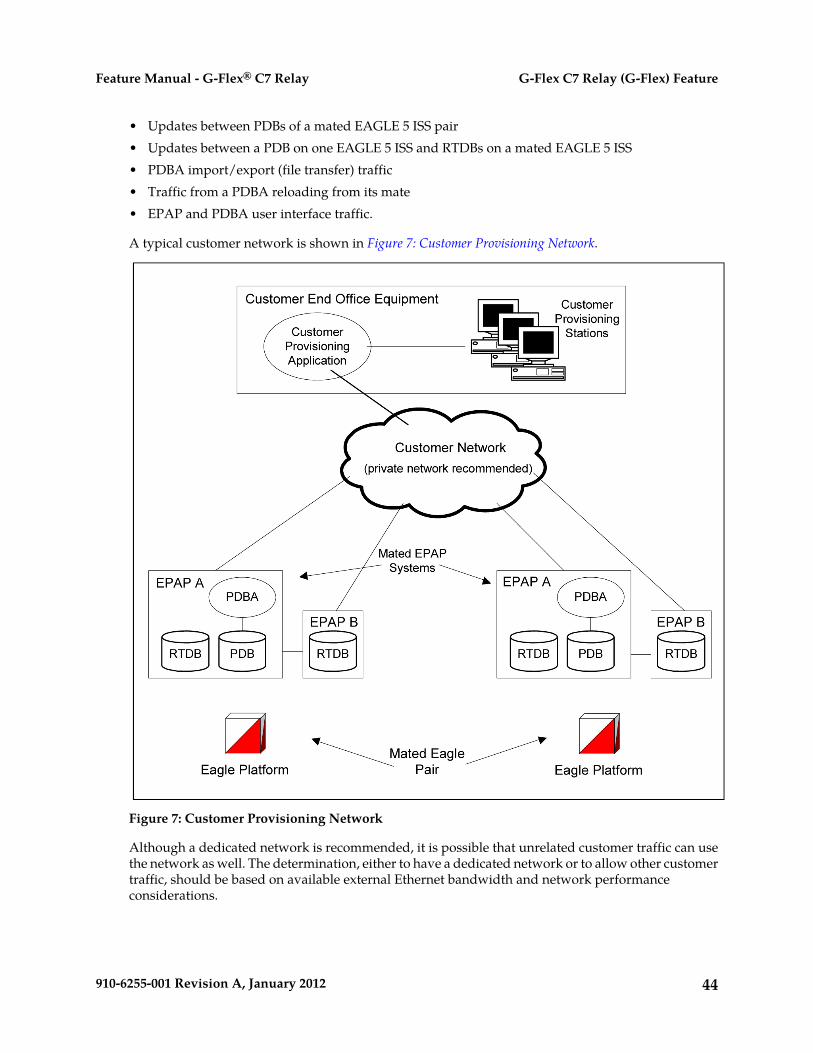
• Updates between PDBs of a mated EAGLE 5 ISS pair• Updates between a PDB on one EAGLE 5 ISS and RTDBs on a mated EAGLE 5 ISS• PDBA import/export (file transfer) traffic• Traffic from a PDBA reloading from its mate• EPAP and PDBA user interface traffic.
A typical customer network is shown in Figure 7: Customer Provisioning Network.
Figure 7: Customer Provisioning Network
Although a dedicated network is recommended, it is possible that unrelated customer traffic can usethe network as well. The determination, either to have a dedicated network or to allow other customertraffic, should be based on available external Ethernet bandwidth and network performanceconsiderations.
44910-6255-001 Revision A, January 2012
G-Flex C7 Relay (G-Flex) FeatureFeature Manual - G-Flex® C7 Relay

EPAP Sync Network
The EPAP sync network carries RTDB and maintenance application traffic between active and standbyEPAP servers on an MPS system. It synchronizes the contents of the RTDBs of both EPAP A and B.The EPAP Sync network is a single Ethernet connection between EPAP A and EPAP B running at100BASE-T, as shown in Figure 8: EPAP Sync Network. The T1200 EPAP Sync network is truncatedwith the EPAP backup DSM connection and communicates through the switch.
Figure 8: EPAP Sync Network
DSM Networks
The DSM networks are shown in Figure 9: DSM Networks. They carry provisioning data from the activeEPAP RTDB to the Service Module cards. They also carry reload and maintenance traffic to the ServiceModule cards.
The DSM networks consist of two Ethernet networks: the main DSM network running at 100BASE-T,and the backup DSM network running at either 10BASE-T or 100Base-T. See Table 11: EPAP IP Addressesin the DSM Network for the link speed. Both Ethernet networks connect EPAP A and EPAP B withevery Service Module card on a single EAGLE 5 ISS platform.
45910-6255-001 Revision A, January 2012
G-Flex C7 Relay (G-Flex) FeatureFeature Manual - G-Flex® C7 Relay

Figure 9: DSM Networks
Maintenance information is sent from the active EPAP to an arbitrarily selected Service Module card.The selected Service Module card is known as the primary Service Module card. Static information isexchanged across this interface at initialization, and dynamic information is exchanged on occasion.
While much of the traditional OAM provisioning and database functionality is implemented on theEPAP, the maintenance reporting mechanism is still the OAM.
The first and second octets of the EPAP network addresses for this network are 192.168. (The first twooctets for private class C networks are defined in RFC 1918.)
The third octet is customer specifiable for each DSM network. It is important to select values that donot interfere with the customer's network addressing scheme.
The fourth octet of the address is specified as follows:
• If the EPAP is configured as “EPAP A”, the fourth octet has a value of 100.• If the EPAP is configured as “EPAP B”, the fourth octet has a value of 200.
Table 11: EPAP IP Addresses in the DSM Network summarizes the contents of each octet.
Table 11: EPAP IP Addresses in the DSM Network
ValueOctet
1921
1682
One customer-provisioned value for DSM network A and another for DSM network B3
46910-6255-001 Revision A, January 2012
G-Flex C7 Relay (G-Flex) FeatureFeature Manual - G-Flex® C7 Relay

ValueOctet
100 for EPAP A and 200 for EPAP B4
Dial-Up PPP Network
The dial-up PPP network allows multiple user-interface sessions to be established with the EPAP. Thenetwork connects a remote EPAP/PDBA user interface terminal with the EPAP in the EAGLE 5 ISS’sMPS subsystem. The dial-up PPP network is illustrated in Figure 10: Dial-Up PPP Network.
Figure 10: Dial-Up PPP Network
47910-6255-001 Revision A, January 2012
G-Flex C7 Relay (G-Flex) FeatureFeature Manual - G-Flex® C7 Relay
Chapter
3G-Flex MAP Layer Routing (G-Flex MLR) Feature
This chapter describes the G-Flex MAP LayerRouting (G-Flex MLR ) feature. G-Flex MLR allows
Topics:
• G-Flex MAP Layer Routing.....49 subscriber digits to be obtained from either the• Limitations.....52 SCCP layer or the MAP layer of a message during
RTDB lookup.
48910-6255-001 Revision A, January 2012

G-Flex MAP Layer Routing
The EAGLE 5 ISS G-Flex feature can perform RTDB subscriber number lookup based either on asubscriber’s E.164 MSISDN number, or the subscriber’s E.212 IMSI number. In some GSM networks,MSCs use an E.214 MGT (Mobile Global Title) number for routing between networks. G-Flex cannotperform database lookup directly with an E.214 MGT number, but it can convert the E.214 MGT intoa E.212 IMSI number, and thus correctly process the message. In an ITU network, when a visitednetwork entity (VLR, GGSN, SGSN, or GMLC) needs to contact a home network entity ( AuC or HLR)given only the IMSI of a subscriber, it will convert the E.212 IMSI into an E.214 MGT. This processapplies only to the first message of a dialogue. Subsequent messages of that same dialogue will berouted using E.164 numbers.
When the SCCP CdPA is truncated by the MSC in a message that is received for G-Flex service, G-Flexneeds to use the subscriber number from the MAP layer for routing.
The G-Flex MLR feature supports G-Flex routing for messages based on the MAP-layer IMSI andMSISDN parameters that does not involve checking the format of the CdPA , though the messagescontain SCCP Called Party Address (CdPA) parameters in ITU E.214 format. The CdPA should containan E.214 number, but its format and content have no bearing on the G-Flex MLR function.
G-Flex MLR processes messages with the MAP operations shown in Table 12: MAP Operations Processedby G-Flex MLR:
Table 12: MAP Operations Processed by G-Flex MLR
ProcessingMAP Operation Name
G-Flex MLR processes messages with MAPoperations that commonly encode the SCCP CdPA
updateLocation
updateGprsLocation GTA in the E.214 format (MGT) where trailingsendParameters IMSI digits may be truncated from the MGT, and
that always include IMSI in the MAP layer.sendAuthenicationInfo
registerSS
activateSS
deactivateSS
interrogateSS
authenticationFailureReport
restoreData
readyForSM
purgeMS
G-Flex MLR processes messages with MAPoperations that include either an IMSI or anMSISDN in the TCAP component.
processUnstructuredSS-Request
sendRoutingInfoForLCS
49910-6255-001 Revision A, January 2012
G-Flex MAP Layer Routing (G-Flex MLR) FeatureFeature Manual - G-Flex® C7 Relay

ProcessingMAP Operation Name
G-Flex MLR processes messages with theAnyTimeInterrogation (ATI) operation, using the
AnyTimeInterrogation
MSISDN from the MAP layer of the ATI messagefor conditioning and RTDB look up. The MSISDNis converted to International format for RTDBsearching based on the Nature of AddressIndicator in the MAP MSISDN parameter. NoHomeRN deletion is required.
For the following MAP Operations, G-Flex MLR uses the GSMOPTS GFLEXMAPLAYERRTGconfiguration option value to determine whether to use the IMSI or MSISDN to obtain subscriberdigits from the MAP layer when performing RTDB lookup:
• updateLocation• updateGprsLocation• sendParameters• sendAuthenicationInfo• AnyTimeInterrogation
The GFLEXMAPLAYERRTG option can have the following values:
• NONE - The G-Flex MLR function is not performed for a message that contains an updateLocation,sendParameters, sendAuthenticationInfo, updateGprsLocation, or AnyTimeInterrogation operationcode. Normal G-Flex processing is applied to the message. The IMSI or MSISDN is taken from theSCCP CdPA parameter for TC-BEGIN messages.
• IMSI - The G-Flex MLR function uses the IMSI for the RTDB lookup, for the updateLocation,sendParameters, sendAuthenticationInfo, and updateGprsLocation operations.
• MSISDN - The G-Flex MLR function uses the MSISDN for the RTDB lookup, for theAnyTimeInterrogation operation.
• All - The G-Flex MLR function uses the IMSI or the MSISDN for the RTDB lookup, based on theoperation code of the message. If the message contains an updateLocation, sendParameters,sendAuthenticationInfo, or updateGprsLocation operation code, the G-Flex MLR function uses theIMSI parameter. If the message contains an AnyTimeInterrogation operation code, the G-Flex MLRfunction uses the MSISDN parameter.
For the operations shown in Table 13: GSMOPTS Configuration Options MAPLYRRTGON andMAPLYRRTGOFF, G-Flex MLR uses the GSMOPTS MAPLYRRTGON configuration option to turnon processing of each specified operation or all operations, and the MAPLYRRTGOFF configurationoption to turn off processing of each specified operation or all operations. The values are specified ina comma-separated list for the option in the chg-gsmopts command. One or both options can bespecified in one command, but the same value cannot be specified in both options in the same command.When ALL is specified for one option, the other option cannot be specified in the same command.
Table 13: GSMOPTS Configuration Options MAPLYRRTGON and MAPLYRRTGOFF
Configuration Option ValueOperation Name
regssregisterSS
actssactivateSS
50910-6255-001 Revision A, January 2012
G-Flex MAP Layer Routing (G-Flex MLR) FeatureFeature Manual - G-Flex® C7 Relay
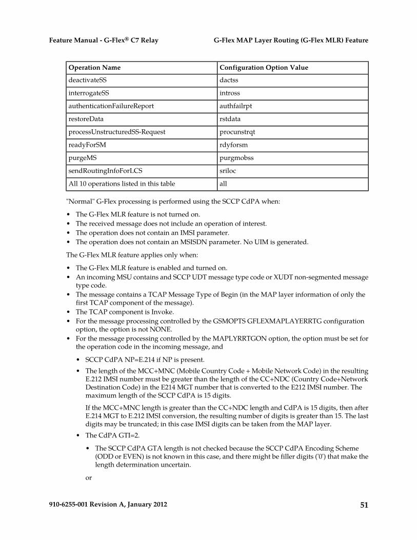
Configuration Option ValueOperation Name
dactssdeactivateSS
introssinterrogateSS
authfailrptauthenticationFailureReport
rstdatarestoreData
procunstrqtprocessUnstructuredSS-Request
rdyforsmreadyForSM
purgmobsspurgeMS
srilocsendRoutingInfoForLCS
allAll 10 operations listed in this table
"Normal" G-Flex processing is performed using the SCCP CdPA when:
• The G-Flex MLR feature is not turned on.• The received message does not include an operation of interest.• The operation does not contain an IMSI parameter.• The operation does not contain an MSISDN parameter. No UIM is generated.
The G-Flex MLR feature applies only when:
• The G-Flex MLR feature is enabled and turned on.• An incoming MSU contains and SCCP UDT message type code or XUDT non-segmented message
type code.• The message contains a TCAP Message Type of Begin (in the MAP layer information of only the
first TCAP component of the message).• The TCAP component is Invoke.• For the message processing controlled by the GSMOPTS GFLEXMAPLAYERRTG configuration
option, the option is not NONE.• For the message processing controlled by the MAPLYRRTGON option, the option must be set for
the operation code in the incoming message, and
• SCCP CdPA NP=E.214 if NP is present.• The length of the MCC+MNC (Mobile Country Code + Mobile Network Code) in the resulting
E.212 IMSI number must be greater than the length of the CC+NDC (Country Code+NetworkDestination Code) in the E214 MGT number that is converted to the E212 IMSI number. Themaximum length of the SCCP CdPA is 15 digits.
If the MCC+MNC length is greater than the CC+NDC length and CdPA is 15 digits, then afterE.214 MGT to E.212 IMSI conversion, the resulting number of digits is greater than 15. The lastdigits may be truncated; in this case IMSI digits can be taken from the MAP layer.
• The CdPA GTI=2.
• The SCCP CdPA GTA length is not checked because the SCCP CdPA Encoding Scheme(ODD or EVEN) is not known in this case, and there might be filler digits ('0') that make thelength determination uncertain.
or
51910-6255-001 Revision A, January 2012
G-Flex MAP Layer Routing (G-Flex MLR) FeatureFeature Manual - G-Flex® C7 Relay

The CdPA GTI=4 and the SCCP CdPA length is 15 digits.
• If the length of the SCCP CdPA GTA is 16 digits and the last digit is a stop digit ('0xF'), thestop digit is treated as a filler digit and the CdPA GTA length is considered to be 15 digits.
• If the CdPA GTI=4, the SCCP CdPA GTA is 8 bytes, and the Encoding Scheme is not BCDODD (1) or BCD EVEN (2), the Encoding Scheme is assumed to be BCD EVEN (2).
The G-Flex MLR UIMs listed in G-Flex-Related UIMs are generated to indicate the following errors inthe IMSI and MSISDN parameter in a message. Normal G-Flex processing is applied to the message.
• Missing IMSI (a UIM is not generated for a missing MSISDN)• Decoding errors such as an IMSI parameter value that does not have at least 5 digits and no more
than 15 digits, or an MSISDN parameter value that does not have at least 1 digit and no more than15 digits
• MSISDN digits with the NAI set to Subscriber or National and the STPOPTS Default Country Code(DEFCC) or Default Network Destination Code (DEFNDC) configuration option is not setappropriately
• Invalid TCAP component
G-Flex MLR affects only the selection of digits for RTDB lookup. All other processing is the same asG-Flex. No changes are made to the MAP layer of the outgoing message; the SCCP layer may bechanged per the provisioned Network Entity parameters in the EPAP (such as Digit Action).
Limitations
ANSI G-Flex traffic at 1700 TPS per DSM card and 5000 or 6800 TPS per E5-SM4G card are not supportedby the G-Flex MLR feature. ANSI traffic operates at the standard G-Flex 850 TPS rate if the G-FlexMLR feature is turned on.
52910-6255-001 Revision A, January 2012
G-Flex MAP Layer Routing (G-Flex MLR) FeatureFeature Manual - G-Flex® C7 Relay
Chapter
4EAGLE 5 ISS Commands
This chapter contains brief descriptions of theEAGLE 5 ISS commands that can be used for
Topics:
• EAGLE 5 ISS Commands.....54 configuration of the G-Flex feature and relatedfeatures and functions.
53910-6255-001 Revision A, January 2012
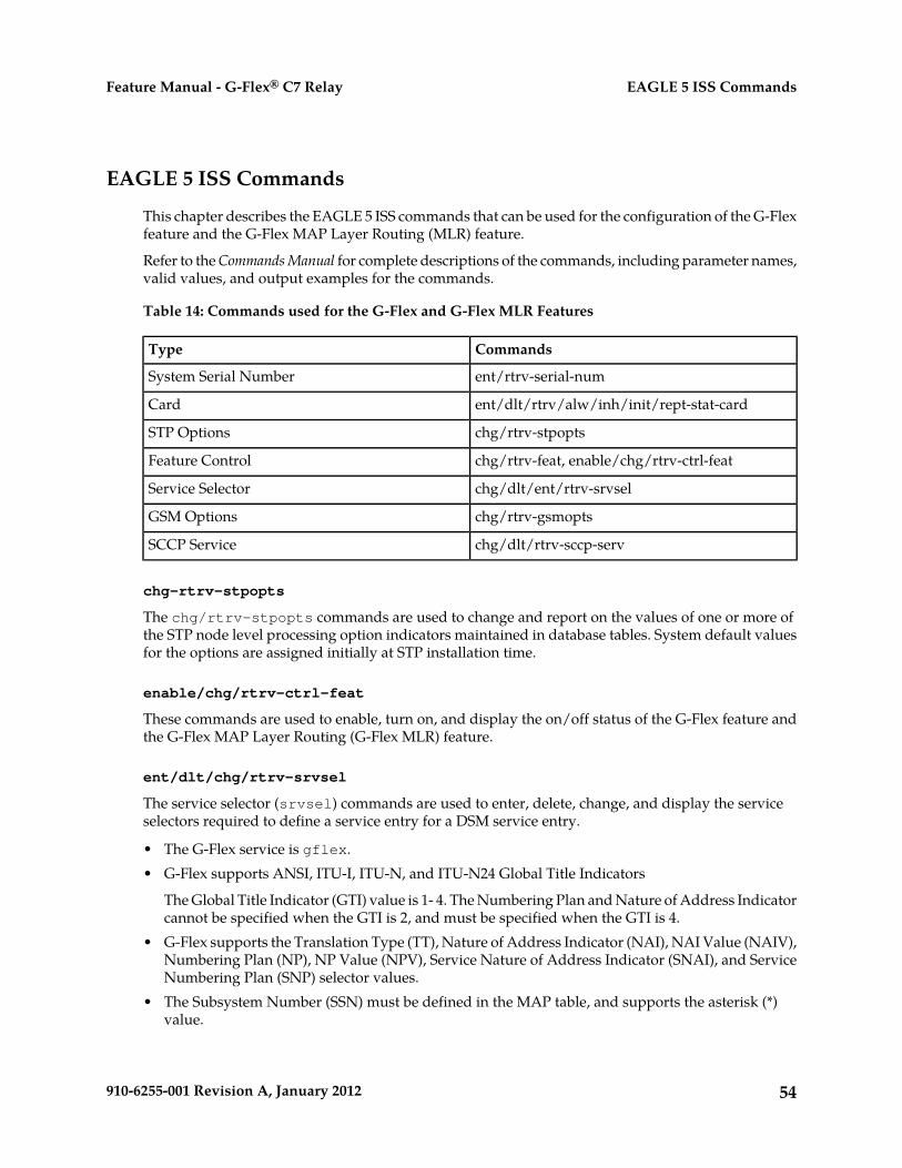
EAGLE 5 ISS Commands
This chapter describes the EAGLE 5 ISS commands that can be used for the configuration of the G-Flexfeature and the G-Flex MAP Layer Routing (MLR) feature.
Refer to the Commands Manual for complete descriptions of the commands, including parameter names,valid values, and output examples for the commands.
Table 14: Commands used for the G-Flex and G-Flex MLR Features
CommandsType
ent/rtrv-serial-numSystem Serial Number
ent/dlt/rtrv/alw/inh/init/rept-stat-cardCard
chg/rtrv-stpoptsSTP Options
chg/rtrv-feat, enable/chg/rtrv-ctrl-featFeature Control
chg/dlt/ent/rtrv-srvselService Selector
chg/rtrv-gsmoptsGSM Options
chg/dlt/rtrv-sccp-servSCCP Service
chg-rtrv-stpopts
The chg/rtrv-stpopts commands are used to change and report on the values of one or more ofthe STP node level processing option indicators maintained in database tables. System default valuesfor the options are assigned initially at STP installation time.
enable/chg/rtrv-ctrl-feat
These commands are used to enable, turn on, and display the on/off status of the G-Flex feature andthe G-Flex MAP Layer Routing (G-Flex MLR) feature.
ent/dlt/chg/rtrv-srvsel
The service selector (srvsel) commands are used to enter, delete, change, and display the serviceselectors required to define a service entry for a DSM service entry.
• The G-Flex service is gflex.• G-Flex supports ANSI, ITU-I, ITU-N, and ITU-N24 Global Title Indicators
The Global Title Indicator (GTI) value is 1- 4. The Numbering Plan and Nature of Address Indicatorcannot be specified when the GTI is 2, and must be specified when the GTI is 4.
• G-Flex supports the Translation Type (TT), Nature of Address Indicator (NAI), NAI Value (NAIV),Numbering Plan (NP), NP Value (NPV), Service Nature of Address Indicator (SNAI), and ServiceNumbering Plan (SNP) selector values.
• The Subsystem Number (SSN) must be defined in the MAP table, and supports the asterisk (*)value.
54910-6255-001 Revision A, January 2012
EAGLE 5 ISS CommandsFeature Manual - G-Flex® C7 Relay
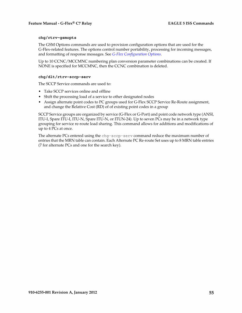
chg/rtrv-gsmopts
The GSM Options commands are used to provision configuration options that are used for theG-Flex-related features. The options control number portability, processing for incoming messages,and formatting of response messages. See G-Flex Configuration Options.
Up to 10 CCNC/MCCMNC numbering plan conversion parameter combinations can be created. IfNONE is specified for MCCMNC, then the CCNC combination is deleted.
chg/dlt/rtrv-sccp-serv
The SCCP Service commands are used to:
• Take SCCP services online and offline• Shift the processing load of a service to other designated nodes• Assign alternate point codes to PC groups used for G-Flex SCCP Service Re-Route assignment,
and change the Relative Cost (RD) of of existing point codes in a group
SCCP Service groups are organized by service (G-Flex or G-Port) and point code network type (ANSI,ITU-I, Spare ITU-I, ITU-N, Spare ITU-N, or ITUN-24). Up to seven PCs may be in a network typegrouping for service re-route load sharing. This command allows for additions and modifications ofup to 4 PCs at once.
The alternate PCs entered using the chg-sccp-serv command reduce the maximum number ofentries that the MRN table can contain. Each Alternate PC Re-route Set uses up to 8 MRN table entries(7 for alternate PCs and one for the search key).
55910-6255-001 Revision A, January 2012
EAGLE 5 ISS CommandsFeature Manual - G-Flex® C7 Relay

Chapter
5G-Flex Feature Configuration
This chapter provides procedures for configuringthe G-Flex feature and the G-Flex MAP LayerRouting feature for use in the EAGLE 5 ISS.
Topics:
• Introduction.....57• G-Flex and G-Flex MLR Configuration
Procedure.....60 The chapter also describes some EPAP provisioningconsiderations.
• Configure the System for HLR Destinations.....62• Adding a Service Module Card.....63• Enable and Turn on the G-Flex Feature.....70• Provision STPOPTS Options for G-Flex.....71• Provisioning the G-Flex Service Selector.....72• Provision the STPOPTS ANSIGFLEX
Option.....76• Provisioning the GSMOPTS Options.....77• Provision the SCCP Service State and Point
Codes.....78• Enable and Turn on the G-Flex MLR Feature....79• The 1100 TPS/DSM for ITU NP Feature.....80• Activating the E5-SM4G Throughput Capacity
Feature.....84
56910-6255-001 Revision A, January 2012

Introduction
The G-Flex feature is configured on the EAGLE 5 ISS and on the EPAP. This chapter describesprerequisites and procedures for the EAGLE 5 ISS configuration only. The EPAP configuration isexplained in the EPAP Administration Manual. This chapter also includes procedures for configurationof the G-Flex MAP Layer Routing (G-Flex MLR) feature for use with G-Flex.
G-Flex and G-Flex MLR Configuration Procedure lists the steps for enabling and turning on the G-Flexfeature and the G-Flex MLR feature, for the provisioning required for the feature, and for theprovisioning of the G-Flex SCCP Service Re-Route Capability and ANSI G-Flex. Each step contains alink or reference to information and procedures to use to complete the step. Feature provisioning canbe performed after the features are enabled and before the features are turned on.
The G-Flex feature and other related features are optional and must be purchased from Tekelec beforethey can be used in your system. If you are not sure whether you have purchased a specific feature,contact your Tekelec Sales or Account Representative.
Note: For an in-service environment, contact the Customer Care Center before continuing to configurethe G-Flex feature. For an environment that is not yet in-service, continue with the configuration.
EPAP Provisioning Blacklist
This feature provides blacklist functions for protected E.164 addresses of network elements, such asHLRs. All G-Flex provisioning data is checked against this blacklist to prevent inadvertent populationof protected E.164 addresses into the RTDB as MSISDNs.
The G-Flex blacklist ranges are stored in the EPAP PDB database. G-Flex blacklist ranges are not sentto or stored in the RTDB.
The provisioning of blacklist ranges does not cause PDB database levels to increment.
The customer is responsible for determining the ranges of address strings that should be considered,protected, and entered into the blacklist. Reliability of this feature depends on the completeness of theblacklist.
CAUTION: If the G-Flex blacklist does not include all protected address strings in thecustomer network and one of those protected address strings is provisioned as a DN, DNBlock, or IMSI, there will be unintended message routing that can cause network outages.
Provisioning of the E.164 addresses for this feature can be done only through the EPAP GUI. TheEPAP GUI is used to retrieve, view, and delete entries in the blacklist. EPAP GUI menus to add anddelete G-Flex blacklist ranges are accessible only to the EPAP PDBA group and the User Administration(uiadmin) user.
A maximum of 1000 blacklist ranges are supported by the EPAP. A valid G-Flex blacklist range isdefined by two address strings of 5-15 hexadecimal digits, where the ending address is greater thanor equal to the beginning address. Address strings must be of the same length. G-Flex blacklist rangescannot overlap. A valid G-Flex blacklist range cannot conflict with DN, DN block, or IMSI values inthe PDB. If a conflict is determined, the blacklist range will be rejected.
The EPAP Provisioning Blacklist feature provides PDBI checks against the blacklist ranges in memorywhen PDBI is used for the provisioning of DNs, DN blocks, and IMSIs. The command is rejected if aconflict is found.
57910-6255-001 Revision A, January 2012
G-Flex Feature ConfigurationFeature Manual - G-Flex® C7 Relay

Refer to the EPAP Administration Manual for more information about using the EPAP ProvisioningBlacklist.
EPAP Entity Provisioning
It is recommended that EPAP entity (SP or RN) administration not be done until after the point codeand/or subsystem number has been entered into the EAGLE 5 ISS MAP table.
• EPAP-administered entity data can possibly become out-of-sync with the EAGLE 5 ISS MAP tablewhen the creation of point codes and/or subsystem numbers in the MAP table is performed afterEPAP database administration.
• If this mismatch is discovered in real-time operations, a UIM (such as SCCP did not route -DPC not in MAP tbl or SCCP did not route - SS not in MAP tbl) is sent to theEAGLE 5 ISS maintenance terminal.
System Prerequisites
Before any feature that is described in this manual can be enabled, the prerequisites listed in Table 15:System Prerequisites are required in the system.
Table 15: System Prerequisites
Verification and ProvisioningPrerequisite
Note: The serial number cannot be changed afterit is entered and locked in the system.
The system serial number must be correct andlocked.
For new installations, the system is shipped withan unlocked serial number. The serial number can
Locate the serial number for the system on a labelaffixed to the control shelf (1100).
be changed if necessary and must be locked afterthe system is on-site. Enter the rtrv-serial-num command to
display the serial number and its locked status.For systems that are being upgraded, the serialnumber is usually already verified and locked. Verify that the displayed serial number is correct
for the system.
If no serial number is displayed, enter theent-serial-num command (without the lockparameter) to provision the serial number thatappears on the control shelf label. Enter thertrv-serial-num command and verify that theserial number was entered correctly.
Enter the ent-serial-num command with thelock=yes parameter to lock the serial number inthe system.
Enter the rept-stat-card:appl=vsccpcommand to list the Service Module cards in thesystem.
A sufficient number of Service Module cards mustbe equipped.
Some features require only E5-SM4G cards andcannot use DSM cards. See specific featureprerequisites, if any, in this section.
If more cards or cards of a different type areneeded, refer to the procedures in the Database
58910-6255-001 Revision A, January 2012
G-Flex Feature ConfigurationFeature Manual - G-Flex® C7 Relay

Verification and ProvisioningPrerequisite
Administration Manual - GTT to add ServiceModule cards or remove DSM cards.
Enter the rtrv-feat command to display theGTT feature status.
The GTT feature must be on in the system.
Some features require an additional GTT-relatedfeature such as EGTT. See the specific featureprerequisites in this section.
If the GTT feature is on, the gtt=on entry appearsin the output.
If the gtt=off entry appears in the output, use theprocedures in the Database Administration Manual- GTT to turn on and provision the GTT featureand any other GTT-related features and functionsthat will be used in the system.
G-Flex Feature Prerequisites
Before the G-Flex feature can be enabled, the following prerequisites are required in the system:
Table 16: G-Flex Feature Prerequisites
Verification and ProvisioningPrerequisite
See Configure the System for HLR Destinations.The system must be configured for HLRdestinations.
Enter the rtrv-stpopts command.The ANSIGFLEX system option cannot be set toYES when G-Flex is used in an ITU system. Verify that the ANSIGFLEX entry does not appear
in the command output or that the ANSIGFLEXentry shows a value of no.
If G-Flex will be used in an ANSI environment,see G-Flex in an ANSI Environmentand G-Flex andG-Flex MLR Configuration Procedure.
Enter the rtrv-ctrl-feat command.The LNP feature cannot be on in the system.
If the LNP feature is on, shown with a quantitygreater than zero for the LNP ported TNs entryin the command output, the feature described inthis manual cannot be enabled.
G-Flex MAP Layer Routing Feature Prerequisites
Before the G-Flex MAP Layer Routing (MLR) feature can be enabled, the following prerequisites arerequired in the system:
59910-6255-001 Revision A, January 2012
G-Flex Feature ConfigurationFeature Manual - G-Flex® C7 Relay
Table 17: G-Flex MAP Layer Routing Feature Prerequisites
Verification and ProvisioningPrerequisite
Enter the rtrv-ctrl-feat command.The G-Flex feature must be enabled and on.
If the G-Flex entry does not appear in the output,follow the steps in the G-Flex and G-Flex MLRConfiguration Procedure to enable and turn on theG-Flex feature.
Enter the rtrv-stpopts command.The ANSIGFLEX system option cannot be set toYes. Verify that the ANSIGFLEX entry does not appear
in the command output or that the ANSIGFLEXentry shows a value of no.
Enter the rtrv-ctrl-feat command.The LNP feature cannot be on in the system.
If the LNP feature is on, shown with a quantitygreater than zero for the LNP ported TNs entryin the command output, the G-Flex MLR featurecannot be enabled.
Enter the rtrv-ctrl-feat command.The E5-SM4G Throughput Capacity featurecannot be enabled in the system. If the E5-SM4G Throughput Capacity feature entry
appears in the command output, the G-Flex MLRfeature cannot be enabled.
G-Flex and G-Flex MLR Configuration Procedure
The EAGLE 5 ISS configuration of the G-Flex feature and the G-Flex MAP Layer Routing (G-Flex MLR)feature consists of the following steps. The steps contain links and references to detailed proceduresand information needed to complete each step.
1. Verify, and provision if needed, the system prerequisites. See System Prerequisites.2. Verify, and provision if needed, the G-Flex feature prerequisites. See G-Flex Feature Prerequisites.3. If the G-Flex MLR feature will be used, verify and provision if needed, the G-Flex MLR feature
prerequisites. See G-Flex MAP Layer Routing Feature Prerequisites.4. Enable and turn on the G-Flex feature. See Enable and Turn on the G-Flex Feature.5. Change the STPOPTS options for the Default Country Code (DEFCC) and Default Network
Destination Code (DEFNDC) to values other than NONE. See Provision STPOPTS Options for G-Flex.6. Provision GSMOPTS options for G-Flex, including the following options. See Provisioning the
GSMOPTS Options.
• E.214 country code and network code (CCNC)• Default GSM mobile country code (DEFMCC)
60910-6255-001 Revision A, January 2012
G-Flex Feature ConfigurationFeature Manual - G-Flex® C7 Relay

• Default GSM mobile network destination code (DEFMNDC)• E.212 mobile country code and mobile network code (MCCMNC)
7. Provision the service selector mechanism to route MSUs to the G-Flex service. See Provisioning theG-Flex Service Selector.
• G-Flex service (gflex)• Translation Type
Specify tt=2 when ANSI G-Flex will be used.• Global Title Indicators - G-Flex supports ANSI, ITU-I, and ITU-N Global Title Indicators.
ITU-N24 is not supported.
ANSI G-Flex uses only ANSI GTI=2 and GTIA=2.
ANSI G-Flex is not supported when the G-Flex MLR feature is enabled.• Nature of Address Indicator (NAI) and Numbering Plan (NP) - required when the GTI value
is 2• Service Nature of Address (SNAI) and Service Numbering Plan (SNP)
8. If G-Flex will be used in an ANSI environment, enable the ANSIGFLEX STPOPTS option. SeeProvision the STPOPTS ANSIGFLEX Option.
9. Set the G-Flex service state to ONLINE. See Provision the SCCP Service State and Point Codes.10. If the G-Flex SCCP Service Re-Route Capability function will be used, provision either alternate point
codes or set the GTT option to YES. See Provision the SCCP Service State and Point Codes.11. If the G-Flex MLR feature will be used, continue with step 12.
If the G-Flex MLR feature will not be used, go to step 13.12. If the G-Flex MLR feature will be used,
a. Enable and turn on the G-Flex MLR feature. See Enable and Turn on the G-Flex MLR Feature.b. Provision the GSMOPTS GFLEXMAPLAYERRTG, MAPLYRRTGON, and MAPLYRRTGOFF
options for the G-Flex MLR feature. See Provisioning the GSMOPTS Options.
13. Verify the operational status of the system.
a. Enter the rept-stat-sccp command to verify that all Service Module cards are loaded andin IS-NR status.
b. Enter the rept-stat-mps command to verify that all Service Module cards and the EPAP areconnected and operational.
c. Enter the rept-stat-db command to verify that database levels are identical for the EPAPPDB and RTDB and the RTDB on each Service Module card.
14. Configure the measurements collection method, scheduling, and reporting if measurements willbe collected for G-Flex.
Refer to the procedures in the Database Administration Manual - System Management for configuringOAM-based measurements, the Measurements Platform feature, the E5-OAM IntegratedMeasurements feature, and the EAGLE OA&M Security feature in the EAGLE 5 ISS.
15. Back up the changes using the chg-db:action=backup:dest=fixed command.
61910-6255-001 Revision A, January 2012
G-Flex Feature ConfigurationFeature Manual - G-Flex® C7 Relay
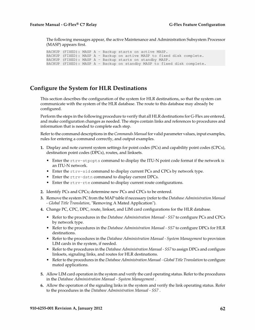
The following messages appear, the active Maintenance and Administration Subsystem Processor(MASP) appears first.BACKUP (FIXED): MASP A - Backup starts on active MASP.BACKUP (FIXED): MASP A - Backup on active MASP to fixed disk complete.BACKUP (FIXED): MASP A - Backup starts on standby MASP.BACKUP (FIXED): MASP A - Backup on standby MASP to fixed disk complete.
Configure the System for HLR Destinations
This section describes the configuration of the system for HLR destinations, so that the system cancommunicate with the system of the HLR database. The route to this database may already beconfigured.
Perform the steps in the following procedure to verify that all HLR destinations for G-Flex are entered,and make configuration changes as needed. The steps contain links and references to procedures andinformation that is needed to complete each step.
Refer to the command descriptions in the Commands Manual for valid parameter values, input examples,rules for entering a command correctly, and output examples.
1. Display and note current system settings for point codes (PCs) and capability point codes (CPCs),destination point codes (DPCs), routes, and linksets.
• Enter the rtrv-stpopts command to display the ITU-N point code format if the network isan ITU-N network.
• Enter the rtrv-sid command to display current PCs and CPCs by network type.• Enter the rtrv-dstn command to display current DPCs.• Enter the rtrv-rte command to display current route configurations.
2. Identify PCs and CPCs; determine new PCs and CPCs to be entered.3. Remove the system PC from the MAP table if necessary (refer to the Database Administration Manual
- Global Title Translation, "Removing A Mated Application").4. Change PC, CPC, DPC, route, linkset, and LIM card configurations for the HLR database.
• Refer to the procedures in the Database Administration Manual - SS7 to configure PCs and CPCsby network type.
• Refer to the procedures in the Database Administration Manual - SS7 to configure DPCs for HLRdestinations.
• Refer to the procedures in the Database Administration Manual - System Management to provisionLIM cards in the system, if needed.
• Refer to the procedures in the Database Administration Manual - SS7 to assign DPCs and configurelinksets, signaling links, and routes for HLR destinations.
• Refer to the procedures in the Database Administration Manual - Global Title Translation to configuremated applications.
5. Allow LIM card operation in the system and verify the card operating status. Refer to the proceduresin the Database Administration Manual - System Management .
6. Allow the operation of the signaling links in the system and verify the link operating status. Referto the procedures in the Database Administration Manual - SS7 .
62910-6255-001 Revision A, January 2012
G-Flex Feature ConfigurationFeature Manual - G-Flex® C7 Relay

7. Verify the service selector changes. Enter the rtrv-srvsel command.8. Back up the changes using the chg-db:action=backup:dest=fixed command.
The following messages appear, the active Maintenance and Administration Subsystem Processor(MASP) appears first.BACKUP (FIXED): MASP A - Backup starts on active MASP.BACKUP (FIXED): MASP A - Backup on active MASP to fixed disk complete.BACKUP (FIXED): MASP A - Backup starts on standby MASP.BACKUP (FIXED): MASP A - Backup on standby MASP to fixed disk complete.
Adding a Service Module Card
This procedure is used to add Service Module cards to the database to support GTT-related featuresand EPAP-related features.
EPAP-related features require Service Module cards running the VSCCP application. The followingcards can be used as Service Module cards running the VSCCP application in the system:
• DSM 4G – a Service Module card with 4 gigabytes of memory and supports Group Ticket Voucher(TVG) and Message Flow Control (MFC)
• E5-SM4G - a Service Module card with 4 gigabytes of memory and supports TVG and MFC• E5-SM8G-B - a Service Module card with 8 gigabytes of memory and supports only MFC
The system can contain a maximum of 32 (31+1) Service Module cards for EPAP-related features withEPAP running on a T1200 AS:
• The following Warning appears when more than 25 Service Module cards have been provisionedin the system and the enable-ctrl-feat command is entered to enable the first EPAP-relatedfeature in the system:Warning: The Eagle must be connected to an EPAP T1200 or higher
• The following Caution appears when the ent-card commend is entered to add the 26th ServiceModule card to the database and any EPAP-related feature is enabled in the system:CAUTION: Please ensure EPAP Application Server is running on hardware supporting 32 SCCP cards e.g.: T1200. Re-enter command within 30 seconds to confirm change.
A Service Module card occupies two card slots. A Service Module card can be inserted in only anodd/even numbered pair of empty card slots of an EAGLE 5 ISS shelf. The even-numbered card slotto the right of the odd-numbered slot where the Service Module card is to be inserted must be empty.A Service Module card cannot be inserted in slots 09 and 10 because slots 09 and 10 of each shelfcontain HMUX cards, HIPR cards, or HIPR2 cards. The Service Module card is connected to the networkthrough the odd-numbered card slot connector.
Note: Service Module cards can be inserted only in slots 01, 03, 05, 07, and 11 of the control shelf(1100).
63910-6255-001 Revision A, January 2012
G-Flex Feature ConfigurationFeature Manual - G-Flex® C7 Relay
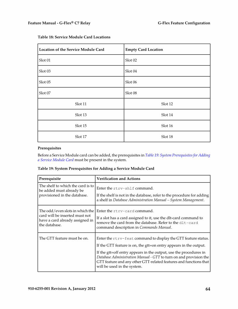
Table 18: Service Module Card Locations
Empty Card LocationLocation of the Service Module Card
Slot 02Slot 01
Slot 04Slot 03
Slot 06Slot 05
Slot 08Slot 07
Slot 12Slot 11
Slot 14Slot 13
Slot 16Slot 15
Slot 18Slot 17
Prerequisites
Before a Service Module card can be added, the prerequisites in Table 19: System Prerequisites for Addinga Service Module Card must be present in the system.
Table 19: System Prerequisites for Adding a Service Module Card
Verification and ActionsPrerequisite
Enter the rtrv-shlf command.The shelf to which the card is tobe added must already beprovisioned in the database. If the shelf is not in the database, refer to the procedure for adding
a shelf in Database Administration Manual – System Management.
Enter the rtrv-card command.The odd/even slots in which thecard will be inserted must not If a slot has a card assigned to it, use the dlt-card command to
remove the card from the database. Refer to the dlt-cardcommand description in Commands Manual.
have a card already assigned inthe database.
Enter the rtrv-feat command to display the GTT feature status.The GTT feature must be on.
If the GTT feature is on, the gtt=on entry appears in the output.
If the gtt=off entry appears in the output, use the procedures inDatabase Administration Manual - GTT to turn on and provision theGTT feature and any other GTT-related features and functions thatwill be used in the system.
64910-6255-001 Revision A, January 2012
G-Flex Feature ConfigurationFeature Manual - G-Flex® C7 Relay
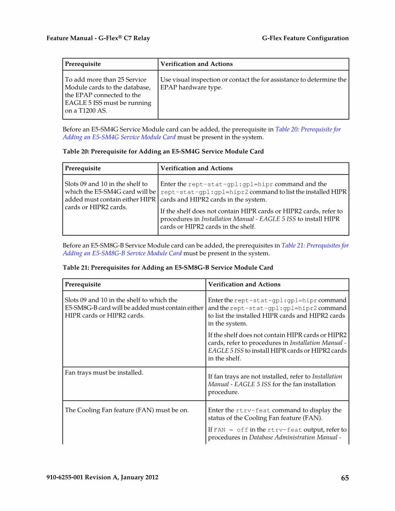
Verification and ActionsPrerequisite
Use visual inspection or contact the for assistance to determine theEPAP hardware type.
To add more than 25 ServiceModule cards to the database,the EPAP connected to theEAGLE 5 ISS must be runningon a T1200 AS.
Before an E5-SM4G Service Module card can be added, the prerequisite in Table 20: Prerequisite forAdding an E5-SM4G Service Module Card must be present in the system.
Table 20: Prerequisite for Adding an E5-SM4G Service Module Card
Verification and ActionsPrerequisite
Enter the rept-stat-gpl:gpl=hipr command and therept-stat-gpl:gpl=hipr2 command to list the installed HIPRcards and HIPR2 cards in the system.
Slots 09 and 10 in the shelf towhich the E5-SM4G card will beadded must contain either HIPRcards or HIPR2 cards. If the shelf does not contain HIPR cards or HIPR2 cards, refer to
procedures in Installation Manual - EAGLE 5 ISS to install HIPRcards or HIPR2 cards in the shelf.
Before an E5-SM8G-B Service Module card can be added, the prerequisites in Table 21: Prerequisites forAdding an E5-SM8G-B Service Module Card must be present in the system.
Table 21: Prerequisites for Adding an E5-SM8G-B Service Module Card
Verification and ActionsPrerequisite
Enter the rept-stat-gpl:gpl=hipr commandand the rept-stat-gpl:gpl=hipr2 command
Slots 09 and 10 in the shelf to which theE5-SM8G-B card will be added must contain eitherHIPR cards or HIPR2 cards. to list the installed HIPR cards and HIPR2 cards
in the system.
If the shelf does not contain HIPR cards or HIPR2cards, refer to procedures in Installation Manual -EAGLE 5 ISS to install HIPR cards or HIPR2 cardsin the shelf.
If fan trays are not installed, refer to InstallationManual - EAGLE 5 ISS for the fan installationprocedure.
Fan trays must be installed.
Enter the rtrv-feat command to display thestatus of the Cooling Fan feature (FAN).
The Cooling Fan feature (FAN) must be on.
If FAN = off in the rtrv-feat output, refer toprocedures in Database Administration Manual -
65910-6255-001 Revision A, January 2012
G-Flex Feature ConfigurationFeature Manual - G-Flex® C7 Relay

Verification and ActionsPrerequisite
System Management to turn on the Cooling Fanfeature (FAN).
Enter the rtrv-stpopts command to displaythe status of the Message Flow Control (MFC)option.
The Message Flow Control (MFC) option must beon.
Refer to procedures in Database AdministrationManual - System Management to turn on theMessage Flow Control (MFC) option.
Refer to Commands Manual for complete descriptions of the commands used in this procedure. Thecomplete descriptions include valid parameter values and output examples.
1. Display the cards in the system by entering the rtrv-card command. Odd-even pairs of cardlocations that do not contain cards (are not listed in the output) and do not contain HMUX, HIPR,or HIPR2 cards can be used for Service Module cards. rlghncxa03w 08-03-15 16:34:56 EST EAGLE 39.2.0 CARD TYPE APPL LSET NAME LINK SLC LSET NAME LINK SLC 1201 LIMDS0 SS7ANSI LS1 A 0 LS1 B 1102 DSM VSCCP ------------ A -- ------------ B -- 1113 GPSM OAM 1114 TDM-A 1115 GPSM OAM 1116 TDM-B 1117 MDAL
;
2. Verify that the Service Module card to be added has been physically installed in the correct cardlocation and the required cabling is installed to connect the card to the EPAP.
CAUTION: If the version of the BPDCM GPL on the Service Module card does notmatch the BPDCM GPL version in the database when the Service Module card isinserted into the card slot, UAM 0002 is generated indicating that these GPL versionsdo not match. If UAM 0002 has been generated, perform the alarm clearing procedurefor UAM 0002 in the Unsolicited Alarm and Information Messages manual beforeproceeding with this procedure.
3. Perform this step only if the card being added will be the 26th Service Module card in the system.
If the card is NOT the 26th Service Module card, continue to Step 4.
Note: The same ent-card command must be entered twice within 30 seconds to complete theprovisioning of the card.
a) Enter the ent-card command the first time for the 26th card.ent-card:loc=<card location>:type=dsm:appl=vsccp
When the command executes the first time and any EPAP-related feature is enabled, the followingcaution appears :CAUTION: Please ensure EPAP Application Server is running on hardware supporting 32 SCCP cards e.g.: T1200. Re-enter command within 30 seconds to confirm change.
66910-6255-001 Revision A, January 2012
G-Flex Feature ConfigurationFeature Manual - G-Flex® C7 Relay

b) Enter the ent-card command a second time for the 26th card to complete the provisioning ofthe card.
c) Go to Step 5.
4. Add the Service Module card to the database, using the ent-card command.ent-card:loc=<card location>:type=dsm:appl=vsccp
5. For an E5-SM4G or E5-SM8G-B card, verify the temperature threshold settings by performing the“Changing the High-Capacity Card Temperature Alarm Thresholds” procedure in DatabaseAdministration Manual - SS7.
6. Verify the change by entering the rtrv-card command with the card location specified.rtrv-card:loc=<card location>
rlghncxa03w 08-03-15 16:34:56 EST EAGLE 39.2.0 CARD TYPE APPL LSET NAME LINK SLC LSET NAME LINK SLC 1301 DSM VSCCP ------------ A -- ------------ B ;
7. Display the current IP link parameters associated with the Service Module card in the database byentering the rtrv-ip-lnk command.RLGHNCXA03W 09-08-24 21:14:37 GMT EAGLE 41.0.0 LOC PORT IPADDR SUBMASK DUPLEX SPEED MACTYPE AUTO MCAST 1107 A ------- -------- HALF 10 DIX NO NO 1107 B ------- -------- HALF 10 DIX NO NO
8. Enter the IP address and other parameter values associated with the Service Module card in thedatabase using the chg-ip-lnk command.
For example, enter:
chg-ip-lnk:loc=1107:port=a:duplex=half:ipaddrr=192.168.122.1:mactype=dix:speed=100:mcast=yes:submask=255.255.255.0
chg-ip-lnk:loc=1107:port=b:duplex=half:ipaddrr=192.168.123.1:mactype=dix:speed=10:mcast=yes:submask=255.255.255.0
where::loc
Card location or slot number of the Service Module card in the EAGLE 5 ISS:port
Ethernet interface Port ID - the physical interface of the Service Module card:ipaddr
IP address for the specified port. This is a TCP/IP address expressed in standard dotnotation. IP addresses consist of the network number of the system and the uniquehost number.
:submask
Subnet mask of the IP interface in the form of an IP address with a restricted range ofvalues
:duplex
Mode of operation of the interface:speed
67910-6255-001 Revision A, January 2012
G-Flex Feature ConfigurationFeature Manual - G-Flex® C7 Relay
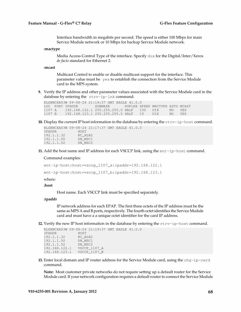
Interface bandwidth in megabits per second. The speed is either 100 Mbps for mainService Module network or 10 Mbps for backup Service Module network.
:mactype
Media Access Control Type of the interface. Specify dix for the Digital/Inter/Xeroxde facto standard for Ethernet 2.
:mcast
Multicast Control to enable or disable multicast support for the interface. Thisparameter value must be yes to establish the connection from the Service Modulecard to the MPS system.
9. Verify the IP address and other parameter values associated with the Service Module card in thedatabase by entering the rtrv-ip-lnk command.RLGHNCXA03W 09-08-24 21:14:37 GMT EAGLE 41.0.0 LOC PORT IPADDR SUBMASK DUPLEX SPEED MACTYPE AUTO MCAST1107 A 192.168.122.1 255.255.255.0 HALF 100 DIX NO YES 1107 B 192.168.123.1 255.255.255.0 HALF 10 DIX NO YES
10. Display the current IP host information in the database by entering the rtrv-ip-host command.RLGHNCXA03W 09-08-24 21:17:37 GMT EAGLE 41.0.0IPADDR HOST192.1.1.32 KC_HLR2192.1.1.50 DN_MSC1192.1.1.52 DN_MSC2
11. Add the host name and IP address for each VSCCP link, using the ent-ip-host command.
Command examples:
ent-ip-host:host=vsccp_1107_a:ipaddr=192.168.122.1
ent-ip-host:host=vsccp_1107_b:ipaddr=192.168.123.1
where::host
Host name. Each VSCCP link must be specified separately.:ipaddr
IP network address for each EPAP. The first three octets of the IP address must be thesame as MPS A and B ports, respectively. The fourth octet identifies the Service Modulecard and must have a a unique octet identifier for the card IP address.
12. Verify the new IP host information in the database by entering the rtrv-ip-host command.RLGHNCXA03W 09-08-24 21:19:37 GMT EAGLE 41.0.0IPADDR HOST192.1.1.32 KC_HLR2192.1.1.50 DN_MSC1192.1.1.52 DN_MSC2192.168.122.1 VSCCP_1107_A192.168.123.1 VSCCP_1107_B
13. Enter local domain and IP router address for the Service Module card, using the chg-ip-cardcommand.
Note: Most customer private networks do not require setting up a default router for the ServiceModule card. If your network configuration requires a default router to connect the Service Module
68910-6255-001 Revision A, January 2012
G-Flex Feature ConfigurationFeature Manual - G-Flex® C7 Relay
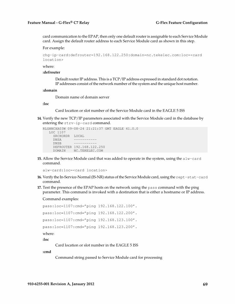
card communication to the EPAP, then only one default router is assignable to each Service Modulecard. Assign the default router address to each Service Module card as shown in this step.
For example:
chg-ip-card:defrouter=192.168.122.250:domain=nc.tekelec.com:loc=<cardlocation>
where::defrouter
Default router IP address. This is a TCP/IP address expressed in standard dot notation.IP addresses consist of the network number of the system and the unique host number.
:domain
Domain name of domain server:loc
Card location or slot number of the Service Module card in the EAGLE 5 ISS
14. Verify the new TCP/IP parameters associated with the Service Module card in the database byentering the rtrv-ip-card command.RLGHNCXA03W 09-08-24 21:21:37 GMT EAGLE 41.0.0 LOC 1107 SRCHORDR LOCAL DNSA ----------- DNSB ----------- DEFROUTER 192.168.122.250 DOMAIN NC.TEKELEC.COM
15. Allow the Service Module card that was added to operate in the system, using the alw-cardcommand.
alw-card:loc=<card location>
16. Verify the In-Service-Normal (IS-NR) status of the Service Module card, using the rept-stat-cardcommand.
17. Test the presence of the EPAP hosts on the network using the pass command with the pingparameter. This command is invoked with a destination that is either a hostname or IP address.
Command examples:
pass:loc=1107:cmd=”ping 192.168.122.100”.
pass:loc=1107:cmd=”ping 192.168.122.200”.
pass:loc=1107:cmd=”ping 192.168.123.100”.
pass:loc=1107:cmd=”ping 192.168.123.200”.
where::loc
Card location or slot number in the EAGLE 5 ISS:cmd
Command string passed to Service Module card for processing
69910-6255-001 Revision A, January 2012
G-Flex Feature ConfigurationFeature Manual - G-Flex® C7 Relay
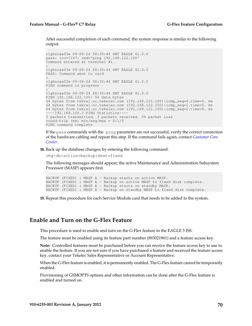
After successful completion of each command, the system response is similar to the followingoutput:
rlghncxa03w 09-08-24 08:30:44 GMT EAGLE 41.0.0pass: loc=1107: cmd="ping 192.168.122.100"Command entered at terminal #1.;rlghncxa03w 09-08-24 08:30:44 GMT EAGLE 41.0.0PASS: Command sent to card;rlghncxa03w 09-08-24 08:30:44 GMT EAGLE 41.0.0PING command in progress;rlghncxa03w 09-08-24 08:30:46 GMT EAGLE 41.0.0PING 192.168.122.100: 56 data bytes64 bytes from tekral.nc.tekelec.com (192.168.122.100):icmp_seq=0.time=5. ms64 bytes from tekral.nc.tekelec.com (192.168.122.100):icmp_seq=1.time=0. ms64 bytes from tekral.nc.tekelec.com (192.168.122.100):icmp_seq=2.time=0. ms----192.168.100.3 PING Statistics----3 packets transmitted, 3 packets received, 0% packet lossround-trip (ms) min/avg/max = 0/1/5PING command complete
If the pass commands with the ping parameter are not successful, verify the correct connectionof the hardware cabling and repeat this step. If the command fails again, contact Customer CareCenter.
18. Back up the database changes, by entering the following command.chg-db:action=backup:dest=fixed
The following messages should appear; the active Maintenance and Administration SubsystemProcessor (MASP) appears first.
BACKUP (FIXED) : MASP A - Backup starts on active MASP.BACKUP (FIXED) : MASP A - Backup on active MASP to fixed disk complete.BACKUP (FIXED) : MASP A - Backup starts on standby MASP.BACKUP (FIXED) : MASP A - Backup on standby MASP to fixed disk complete.
19. Repeat this procedure for each Service Module card that needs to be added to the system.
Enable and Turn on the G-Flex Feature
This procedure is used to enable and turn on the G-Flex feature in the EAGLE 5 ISS.
The feature must be enabled using its feature part number (893021901) and a feature access key.
Note: Controlled features must be purchased before you can receive the feature access key to use toenable the feature. If you are not sure if you have purchased a feature and received the feature accesskey, contact your Tekelec Sales Representative or Account Representative.
When the G-Flex feature is enabled, it is permanently enabled. The G-Flex feature cannot be temporarilyenabled.
Provisioning of GSMOPTS options and other information can be done after the G-Flex feature isenabled and turned on.
70910-6255-001 Revision A, January 2012
G-Flex Feature ConfigurationFeature Manual - G-Flex® C7 Relay
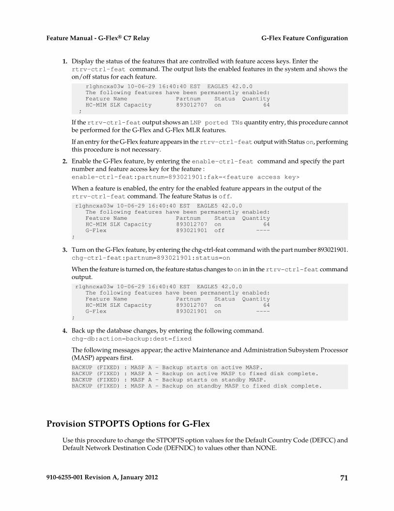
1. Display the status of the features that are controlled with feature access keys. Enter thertrv-ctrl-feat command. The output lists the enabled features in the system and shows theon/off status for each feature. rlghncxa03w 10-06-29 16:40:40 EST EAGLE5 42.0.0 The following features have been permanently enabled: Feature Name Partnum Status Quantity HC-MIM SLK Capacity 893012707 on 64 ;
If the rtrv-ctrl-feat output shows an LNP ported TNs quantity entry, this procedure cannotbe performed for the G-Flex and G-Flex MLR features.
If an entry for the G-Flex feature appears in the rtrv-ctrl-feat output with Status on, performingthis procedure is not necessary.
2. Enable the G-Flex feature, by entering the enable-ctrl-feat command and specify the partnumber and feature access key for the feature :enable-ctrl-feat:partnum=893021901:fak=<feature access key>
When a feature is enabled, the entry for the enabled feature appears in the output of thertrv-ctrl-feat command. The feature Status is off. rlghncxa03w 10-06-29 16:40:40 EST EAGLE5 42.0.0 The following features have been permanently enabled: Feature Name Partnum Status Quantity HC-MIM SLK Capacity 893012707 on 64 G-Flex 893021901 off ----;
3. Turn on the G-Flex feature, by entering the chg-ctrl-feat command with the part number 893021901.chg-ctrl-feat:partnum=893021901:status=on
When the feature is turned on, the feature status changes to on in in the rtrv-ctrl-feat commandoutput. rlghncxa03w 10-06-29 16:40:40 EST EAGLE5 42.0.0 The following features have been permanently enabled: Feature Name Partnum Status Quantity HC-MIM SLK Capacity 893012707 on 64 G-Flex 893021901 on ----;
4. Back up the database changes, by entering the following command.chg-db:action=backup:dest=fixed
The following messages appear; the active Maintenance and Administration Subsystem Processor(MASP) appears first.BACKUP (FIXED) : MASP A - Backup starts on active MASP.BACKUP (FIXED) : MASP A - Backup on active MASP to fixed disk complete.BACKUP (FIXED) : MASP A - Backup starts on standby MASP.BACKUP (FIXED) : MASP A - Backup on standby MASP to fixed disk complete.
Provision STPOPTS Options for G-Flex
Use this procedure to change the STPOPTS option values for the Default Country Code (DEFCC) andDefault Network Destination Code (DEFNDC) to values other than NONE.
71910-6255-001 Revision A, January 2012
G-Flex Feature ConfigurationFeature Manual - G-Flex® C7 Relay

When the G-Flex feature has been enabled, the STP options for the default country code and the defaultnetwork destination code must be changed from NONE to appropriate values for G-Flex. Thechg-stpopts and rtrv-stpopts commands support the defcc, defndc and dsmaud parametersfor the G-Flex feature.
The default country code (defcc) parameter and default network destination code (defndc) parametercan be provisioned for G-Flex after the G-Flex feature is enabled. The defcc and defndc parametervalues must be changed from NONE to appropriated values before the G-Flex feature can be turnedon in the system.
In the rtrv-stpopts command output:
• The defcc and defndc parameters are displayed with value NONE when the G-Flex feature isenabled.
• The dsmaud parameter is displayed with value OFF when the G-Flex feature is turned on.
After the feature is turned on:
• The defcc and defndc parameter values cannot be set to NONE.• The DSM audit running state (dsmaud) parameter of the chg-stpopts command can be
provisioned for G-Flex.
1. Verify the defcc and defndc STP option parameter values. Enter the rtrv-stpopts command.2. Change the defcc and defndc STP option parameter values to the desired values that are not NONE
for the G-Flex feature, using the chg-stpopts command.3. Verify any changes. Enter the rtrv-stpopts command.4. Back up the changes using the chg-db:action=backup:dest=fixed command.
The following messages appear, the active Maintenance and Administration Subsystem Processor(MASP) appears first.BACKUP (FIXED): MASP A - Backup starts on active MASP.BACKUP (FIXED): MASP A - Backup on active MASP to fixed disk complete.BACKUP (FIXED): MASP A - Backup starts on standby MASP.BACKUP (FIXED): MASP A - Backup on standby MASP to fixed disk complete.
Provisioning the G-Flex Service Selector
The procedures in this section describe how to add, change, and remove a service selector. Theinformation is indicated that is specific to G-Flex.
Refer to the Commands Manual for descriptions of the commands that are used in these procedures,including parameter names, valid values, rules for using the commands correctly, and output examples.
Adding a G-Flex Service Selector
This procedure is used to add an ITU service selector for the G-Flex feature. (If G-Flex will be used inan ANSI environment, go to x.
The G-Flex feature must be enabled and turned on before a G-Flex service selector can be added.
1. Verify that the G-Flex feature is enabled and turned on, by entering the rtrv-ctrl-feat command.
72910-6255-001 Revision A, January 2012
G-Flex Feature ConfigurationFeature Manual - G-Flex® C7 Relay

If the G-Flex feature is enabled and turned on, the status of the G-Flex entry is on. rlghncxa03w 09-06-29 16:40:40 EST EAGLE5 41.1.0 The following features have been permanently enabled: Feature Name Partnum Status Quantity HC-MIM SLK Capacity 893012707 on 64 G-Flex 893021901 on ---- ;
• If the G-Flex feature is enabled and turned on, continue with Step 2.• If the G-Flex feature is not enabled or turned on, go to Enable and Turn on the G-Flex Feature to
enable and turn on the G-Flex feature. Then continue with Step 2.
2. Display any existing G-Flex service selectors in the database, by entering thertrv-srvsel:serv=gflex command.
3. Add new G-Flex service selectors, using the ent-srvsel command.This command assigns applicable service selectors required to specify the service entry for ServiceModule services.For an ANSI network, for example, the following commands show how to set up service selectorcombinations for G-Flex services:
ent-srvsel:gtia=2:tt=10:snp=e164:snai=intl:serv:gflexent-srvsel:gtia=2:tt=11:snp=e164:snai=natl:serv:gflexent-srvsel:gtia=2:tt=12:snp=e164:snai=sub:serv:gflex
For an ITU-I network, for example, enter the following command:
ent-srvsel:gtii=4:tt=1:snp=e164:snai=intl:serv:gflex:nai=intl :np=e164
where::gti/gtia/gtii/gtin
Specifies the global title translation indicator (2 = ANSI, ITU; 4 = ITU).:tt - specifiesthe translation type.
:snpDefines the service numbering plan (e164, e212, or e214).
:snaiSpecifies the international Service Nature of Address Indicator.
:servSpecifies the service feature.
:naiSpecifies the nature of address indicator.
:npSpecifies the numbering plan.
4. Verify the changes by entering the rtrv-srvsel command with the parameters and values usedin Step 3.
5. Enter the chg-sccp-serv:serv=gflex:state=online command to set the G-Flex servicestatus to online.
6. Back up the changes using the chg-db:action=backup:dest=fixed command.
73910-6255-001 Revision A, January 2012
G-Flex Feature ConfigurationFeature Manual - G-Flex® C7 Relay

The following messages appear, the active Maintenance and Administration Subsystem Processor(MASP) appears first.BACKUP (FIXED): MASP A - Backup starts on active MASP.BACKUP (FIXED): MASP A - Backup on active MASP to fixed disk complete.BACKUP (FIXED): MASP A - Backup starts on standby MASP.BACKUP (FIXED): MASP A - Backup on standby MASP to fixed disk complete.
Removing a Service Selector
This procedure is used to remove a service selector from the database.
To remove a service selector, the GTI, GTII, GTIN, tt, and ssn parameter values must be entered asshown in the rtrv-srvsel output.
These parameters can also be used to limit the amount of information displayed with the rtrv-srvselcommand.
1. Display the service selectors in the database, by entering the rtrv-srvsel command.2. Remove the service selector from the database, using the dlt-srvsel command.3. Verify the changes by entering the rtrv-srvsel command with the parameters and values used
in Step 2.4. Back up the changes using the chg-db:action=backup:dest=fixed command.
The following messages appear, the active Maintenance and Administration Subsystem Processor(MASP) appears first.BACKUP (FIXED): MASP A - Backup starts on active MASP.BACKUP (FIXED): MASP A - Backup on active MASP to fixed disk complete.BACKUP (FIXED): MASP A - Backup starts on standby MASP.BACKUP (FIXED): MASP A - Backup on standby MASP to fixed disk complete.
Changing an Existing Service Selector to a G-Flex Service Selector
This procedure is used to change an existing non-G-Flex service selector to a G-Flex service selector.
The only parameter that can be changed using this procedure is the nserv parameter, to specify thenew DSM service type (gflex):
The chg-srvsel command requires that the following parameters be specified with the values shownin the rtrv-srvsel output for the service selector that is being changed. If any of these parametervalues need to be changed for a new G-Flex service selector, use the the procedure in Removing a ServiceSelector to remove the existing service selector. Then use the procedure in Adding a G-Flex ServiceSelector to add the new G-Flex service selector with the new parameter information.:gtii/gtin/gtin24
Global title indicator for ITU international (gtii) and ITU national using 14-bit pointcodes (gtin).
:ttTranslation type
:ssnSubsystem number
:nai
74910-6255-001 Revision A, January 2012
G-Flex Feature ConfigurationFeature Manual - G-Flex® C7 Relay

Nature of address indicator:naiv
Nature of address indicator value:np
Numbering plan:npv
Numbering plan value
1. Display the service selectors in the database, using the rtrv-srvsel command.
If the rtrv-srvsel output shows G-Flex service selectors, go to Step 3.
2. Verify that the G-Flex feature is enabled and turned on, by entering the rtrv-ctrl-feat command.If the feature is enabled and turned on, the status of the entry is on. rlghncxa03w 09-06-29 16:40:40 EST EAGLE5 41.1.0 The following features have been permanently enabled: Feature Name Partnum Status Quantity HC-MIM SLK Capacity 893012707 on 64 G-Flex 893021901 on ----;
• If the G-Flex feature is not enabled or turned on, go to Enable and Turn on the G-Flex Feature toenable and turn on the feature. Continue with Step 3.
• If the G-Flex feature is enabled and turned on, continue with Step 3.
3. Change the service selector, using the chg-srvsel command.
If the SNP, or SNAI parameter values are shown as dashes in the rtrv-srvsel output, theseparameters cannot be specified with the chg-srvsel command.
If the gtii/gtin/gtin24 parameter value is 2, the np, nai, npv, and naiv parameters cannot be specifiedwith the chg-srvsel command.
If the gtii/gtin/gtin24 parameter value is 4, either the np and nai, or the npv and naiv parametersmust be specified with the chg-srvsel command. The np and nai parameters can be specifiedin place of the npv and naiv parameters, and the npv and naiv parameters can be specified in placeof the np and naiv parameters, as long as parameter values be specified correspond to the valuesshown in the rtrv-srvsel output. Refer to the chg-srvsel command description in CommandsManual.
4. Verify the changes by entering the rtrv-srvsel command with the serv=gflex parameter andthe values for the other parameters used in Step 3.
5. Back up the changes using the chg-db:action=backup:dest=fixed command.
The following messages appear, the active Maintenance and Administration Subsystem Processor(MASP) appears first.BACKUP (FIXED): MASP A - Backup starts on active MASP.BACKUP (FIXED): MASP A - Backup on active MASP to fixed disk complete.BACKUP (FIXED): MASP A - Backup starts on standby MASP.BACKUP (FIXED): MASP A - Backup on standby MASP to fixed disk complete.
75910-6255-001 Revision A, January 2012
G-Flex Feature ConfigurationFeature Manual - G-Flex® C7 Relay

Provision the STPOPTS ANSIGFLEX Option
Use this procedure to provision the ANSIGFLEX option for allowing 1700 TPS per DSM for G-Flex inan ANSI environment.
The ANSIGFLEX system option can be set to YES only if:
• The G-Flex feature is on.• No other EPAP-related feature or any ELAP-related feature is on.• No ITU service selectors are provisioned.
The only service selectors that can be used when the system option is on are GTI or GTIA ,SERV=GFLEX, and TT=2.
A check for ANSI service selectors is made before allowing the ANSIGFLEX system option to setto YES.
The ANSIGFLEX system option can be set to NO after it has been set to YES(chg-stpopts:ansgflex=no). DSM card TPS granting is reduced to 850 TPS when the optionsetting is NO. A notification to the user concerning the reduction in SCCP capacity is generated.
1. Verify that the G-Flex feature is on. Enter the rtrv-ctrl-feat command.
• If the G-Flex feature is on (the G-Flex entry appears in the command output), continue withStep 2.
• If the G-Flex feature is not on, (the entry is not in the output or the Status is off in the entry),go to G-Flex and G-Flex MLR Configuration Procedure to enable, turn on, and provision the G-Flexfeature. Then continue with Step 2.
2. Display any provisioned service selectors. Enter the rtrv-srvsel command.
• If the correct ANSI service selectors are provisioned, continue with Step 7.• If there are no service selectors provisioned or there are ITU service selectors provisioned, go
to
• Removing a Service Selector to remove ITU service selectors (selectors that are not GTI or GTIAand tt=2)
• Adding a G-Flex Service Selector to add ANSI service selectors
3. Enable the STPOPTS ANSIGFLEX option. Enter the chg-stpopts:ansigflex=yes command.4. Back up the changes using the chg-db:action=backup:dest=fixed command.
The following messages appear, the active Maintenance and Administration Subsystem Processor(MASP) appears first.BACKUP (FIXED): MASP A - Backup starts on active MASP.BACKUP (FIXED): MASP A - Backup on active MASP to fixed disk complete.BACKUP (FIXED): MASP A - Backup starts on standby MASP.BACKUP (FIXED): MASP A - Backup on standby MASP to fixed disk complete.
76910-6255-001 Revision A, January 2012
G-Flex Feature ConfigurationFeature Manual - G-Flex® C7 Relay

Provisioning the GSMOPTS Options
This procedure is used to provision the configuration options for the G-Flex feature and the G-FlexMLR feature.
See G-Flex Configuration Options for information and considerations about provisioning G-Flex andG-Flex MLR configuration options.
Refer to the command descriptions in the Commands Manual for valid parameter values, input examples,rules for entering the commands correctly, and output examples for the commands used in thisprocedure.
1. Verify that the G-Flex feature is enabled and turned on, by entering the rtrv-ctrl-feat command.
• If the G-Flex feature is enabled and turned on (the entry appears in the output with Status on),continue with Step 2. rlghncxa03w 09-06-29 16:40:40 EST EAGLE5 41.1.0 The following features have been permanently enabled: Feature Name Partnum Status Quantity HC-MIM SLK Capacity 893012707 on 64 G-Flex 893021901 on ----;
• If the G-Flex feature is not enabled (the entry does not appear in the output) or is not turned on(the entry appears with Status off, go to Enable and Turn on the G-Flex Feature to enable and turnon the feature. Then continue with Step 2.
2. Display the current settings of the feature options. Enter the rtrv-gsmopts command.3. Change the GSMOPTS options for G-Flex to the required values.4. Verify the changes. Enter the rtrv-gsmopts command.5. Is the G-Flex MLR feature to be used with the G-Flex feature?.
• If the G-Flex MLR feature will NOT be used, go to Step 9.• If the G-Flex MLR feature WILL BE used, continue with Step 6.
6. If the G-Flex MLR feature will be used, verify that the G-Flex MLR feature is enabled and turnedon, by entering the rtrv-ctrl-feat command.
• If the G-Flex MLR feature is enabled and turned on (the entry appears in the output with Statuson), continue with Step 7. rlghncxa03w 09-06-29 16:40:40 EST EAGLE5 41.1.0 The following features have been permanently enabled: Feature Name Partnum Status Quantity HC-MIM SLK Capacity 893012707 on 64 G-Flex 893021901 on ---- G-Flex MLR 893021701 on ----;
• If the G-Flex MLR feature is not enabled (the entry does not appear in the output) or is notturned on (the entry appears with Status off, go to Enable and Turn on the G-Flex MLR Feature toenable and turn on the feature. Then continue with Step 7.
77910-6255-001 Revision A, January 2012
G-Flex Feature ConfigurationFeature Manual - G-Flex® C7 Relay
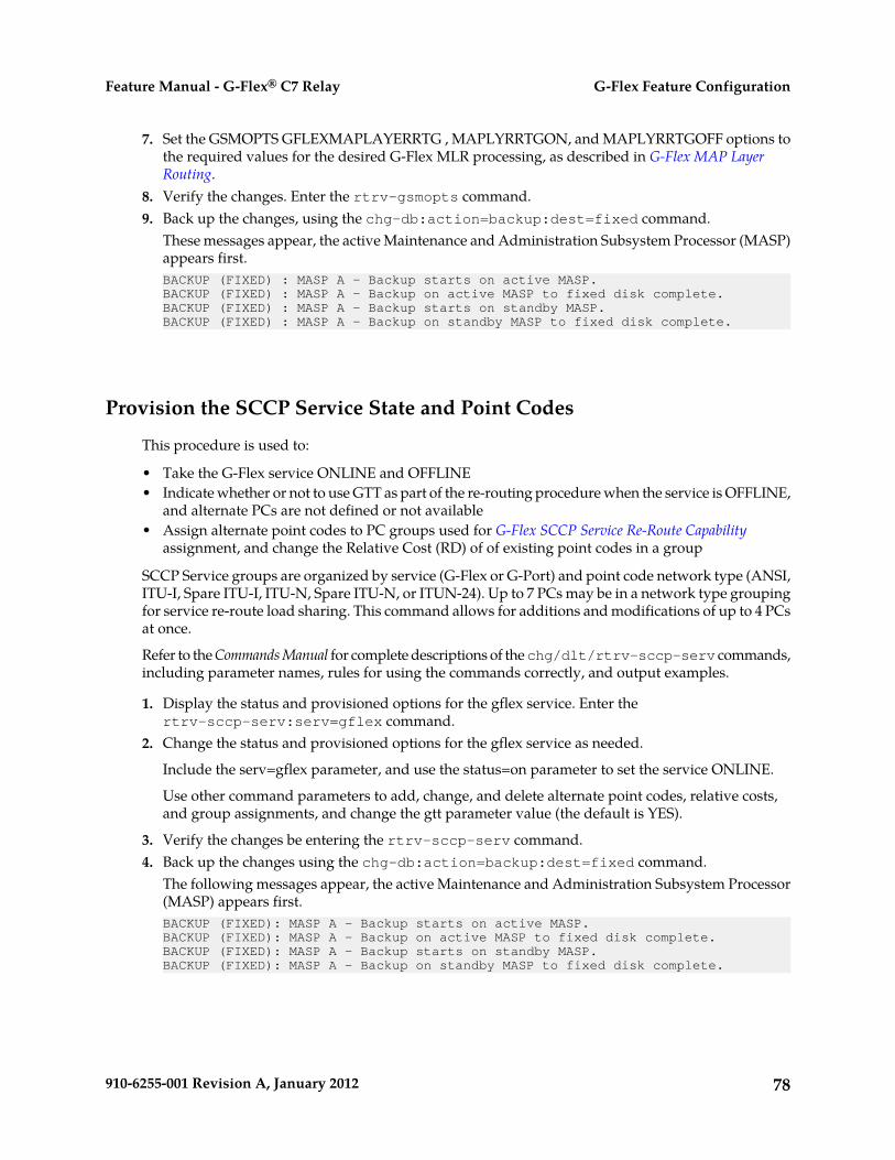
7. Set the GSMOPTS GFLEXMAPLAYERRTG , MAPLYRRTGON, and MAPLYRRTGOFF options tothe required values for the desired G-Flex MLR processing, as described in G-Flex MAP LayerRouting.
8. Verify the changes. Enter the rtrv-gsmopts command.9. Back up the changes, using the chg-db:action=backup:dest=fixed command.
These messages appear, the active Maintenance and Administration Subsystem Processor (MASP)appears first.BACKUP (FIXED) : MASP A - Backup starts on active MASP.BACKUP (FIXED) : MASP A - Backup on active MASP to fixed disk complete.BACKUP (FIXED) : MASP A - Backup starts on standby MASP.BACKUP (FIXED) : MASP A - Backup on standby MASP to fixed disk complete.
Provision the SCCP Service State and Point Codes
This procedure is used to:
• Take the G-Flex service ONLINE and OFFLINE• Indicate whether or not to use GTT as part of the re-routing procedure when the service is OFFLINE,
and alternate PCs are not defined or not available• Assign alternate point codes to PC groups used for G-Flex SCCP Service Re-Route Capability
assignment, and change the Relative Cost (RD) of of existing point codes in a group
SCCP Service groups are organized by service (G-Flex or G-Port) and point code network type (ANSI,ITU-I, Spare ITU-I, ITU-N, Spare ITU-N, or ITUN-24). Up to 7 PCs may be in a network type groupingfor service re-route load sharing. This command allows for additions and modifications of up to 4 PCsat once.
Refer to the Commands Manual for complete descriptions of the chg/dlt/rtrv-sccp-serv commands,including parameter names, rules for using the commands correctly, and output examples.
1. Display the status and provisioned options for the gflex service. Enter thertrv-sccp-serv:serv=gflex command.
2. Change the status and provisioned options for the gflex service as needed.
Include the serv=gflex parameter, and use the status=on parameter to set the service ONLINE.
Use other command parameters to add, change, and delete alternate point codes, relative costs,and group assignments, and change the gtt parameter value (the default is YES).
3. Verify the changes be entering the rtrv-sccp-serv command.4. Back up the changes using the chg-db:action=backup:dest=fixed command.
The following messages appear, the active Maintenance and Administration Subsystem Processor(MASP) appears first.BACKUP (FIXED): MASP A - Backup starts on active MASP.BACKUP (FIXED): MASP A - Backup on active MASP to fixed disk complete.BACKUP (FIXED): MASP A - Backup starts on standby MASP.BACKUP (FIXED): MASP A - Backup on standby MASP to fixed disk complete.
78910-6255-001 Revision A, January 2012
G-Flex Feature ConfigurationFeature Manual - G-Flex® C7 Relay

Enable and Turn on the G-Flex MLR Feature
This procedure is used to enable the G-Flex MAP Layer Routing (G-Flex MLR) feature in the EAGLE5 ISS.
The feature must be enabled using its feature part number (893021701) and a feature access key.
Note: Controlled features must be purchased before you can receive the feature access key to use toenable the feature. If you are not sure if you have purchased a feature and received the feature accesskey, contact your Tekelec Sales Representative or Account Representative.
When the G-Flex MLR feature is e enabled, it is permanently enabled. The G-Flex MLR feature cannotbe temporarily enabled.
Provisioning of the GSMOPTS options can be done after the G-Flex MLR feature is enabled and turnedon.
1. Display the status of the features that are controlled with feature access keys. Enter thertrv-ctrl-feat command. The output lists the enabled features in the system and shows theon/off status for each feature. rlghncxa03w 10-06-29 16:40:40 EST EAGLE5 42.0.0 The following features have been permanently enabled: Feature Name Partnum Status Quantity HC-MIM SLK Capacity 893012707 on 64 ;
If the rtrv-ctrl-feat output shows a LNP ported TNs quantity entry, this procedure cannotbe performed for the G-Flex MLR feature.
If an entry for the G-Flex MLR feature appears in the rtrv-ctrl-feat output with Status on,performing this procedure is not necessary.
2. Enable the G-Flex MAP Layer Routing feature. Enter the enable-ctrl-feat command andspecify the part number and feature access key for the feature.enable-ctrl-feat:partnum=893021701:fak=<fak>
When a feature is enabled, the entry for the enabled feature appears in the output of thertrv-ctrl-feat command. The feature Status is offrlghncxa03w 10-06-29 16:40:40 EST EAGLE5 42.0.0 The following features have been permanently enabled: Feature Name Partnum Status Quantity HC-MIM SLK Capacity 893012707 on 64 G-Flex 893021901 on ---- G-Flex MLR 893021701 off ----
3. Turn on the G-Flex MAP Layer Routing Feature, by entering the chg-ctrl-feat command:chg-ctrl-feat:partnum=893021701:status=on
When the feature is turned on, the feature status changes to on in the rtrv-ctrl-feat commandoutput.rlghncxa03w 10-06-29 16:40:40 EST EAGLE5 42.0.0 The following features have been permanently enabled: Feature Name Partnum Status Quantity HC-MIM SLK Capacity 893012707 on 64 G-Flex 893021901 on ----
79910-6255-001 Revision A, January 2012
G-Flex Feature ConfigurationFeature Manual - G-Flex® C7 Relay
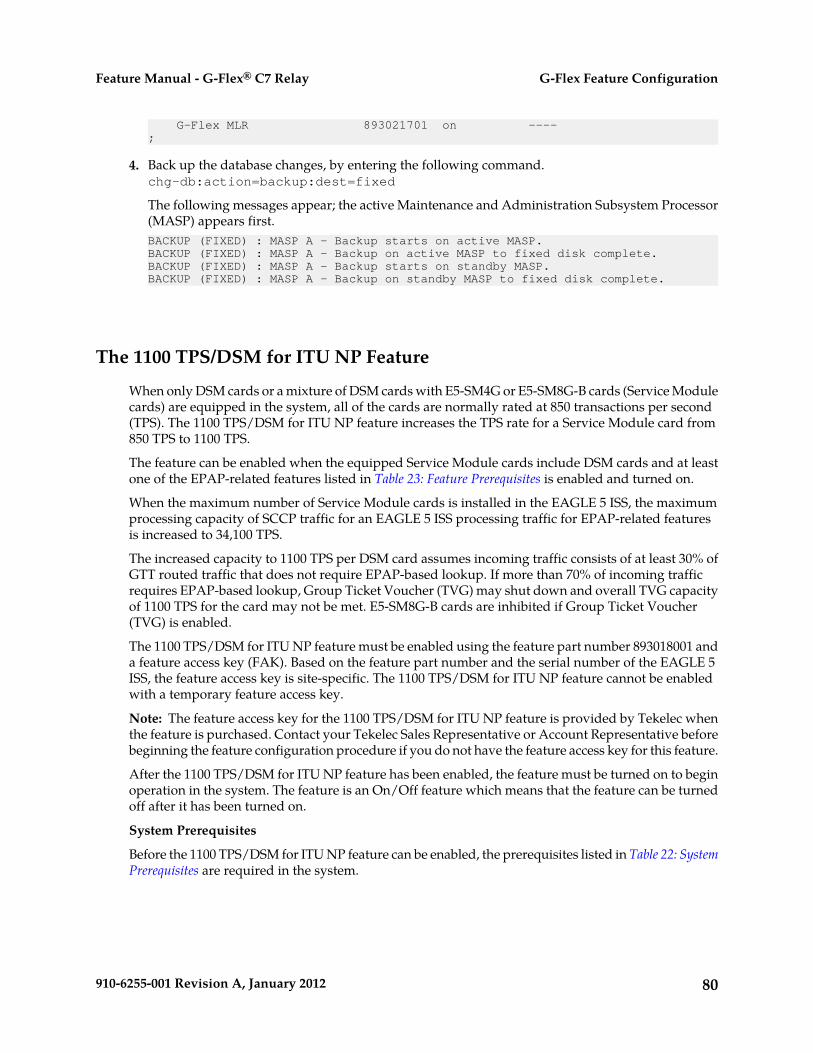
G-Flex MLR 893021701 on ----;
4. Back up the database changes, by entering the following command.chg-db:action=backup:dest=fixed
The following messages appear; the active Maintenance and Administration Subsystem Processor(MASP) appears first.BACKUP (FIXED) : MASP A - Backup starts on active MASP.BACKUP (FIXED) : MASP A - Backup on active MASP to fixed disk complete.BACKUP (FIXED) : MASP A - Backup starts on standby MASP.BACKUP (FIXED) : MASP A - Backup on standby MASP to fixed disk complete.
The 1100 TPS/DSM for ITU NP Feature
When only DSM cards or a mixture of DSM cards with E5-SM4G or E5-SM8G-B cards (Service Modulecards) are equipped in the system, all of the cards are normally rated at 850 transactions per second(TPS). The 1100 TPS/DSM for ITU NP feature increases the TPS rate for a Service Module card from850 TPS to 1100 TPS.
The feature can be enabled when the equipped Service Module cards include DSM cards and at leastone of the EPAP-related features listed in Table 23: Feature Prerequisites is enabled and turned on.
When the maximum number of Service Module cards is installed in the EAGLE 5 ISS, the maximumprocessing capacity of SCCP traffic for an EAGLE 5 ISS processing traffic for EPAP-related featuresis increased to 34,100 TPS.
The increased capacity to 1100 TPS per DSM card assumes incoming traffic consists of at least 30% ofGTT routed traffic that does not require EPAP-based lookup. If more than 70% of incoming trafficrequires EPAP-based lookup, Group Ticket Voucher (TVG) may shut down and overall TVG capacityof 1100 TPS for the card may not be met. E5-SM8G-B cards are inhibited if Group Ticket Voucher(TVG) is enabled.
The 1100 TPS/DSM for ITU NP feature must be enabled using the feature part number 893018001 anda feature access key (FAK). Based on the feature part number and the serial number of the EAGLE 5ISS, the feature access key is site-specific. The 1100 TPS/DSM for ITU NP feature cannot be enabledwith a temporary feature access key.
Note: The feature access key for the 1100 TPS/DSM for ITU NP feature is provided by Tekelec whenthe feature is purchased. Contact your Tekelec Sales Representative or Account Representative beforebeginning the feature configuration procedure if you do not have the feature access key for this feature.
After the 1100 TPS/DSM for ITU NP feature has been enabled, the feature must be turned on to beginoperation in the system. The feature is an On/Off feature which means that the feature can be turnedoff after it has been turned on.
System Prerequisites
Before the 1100 TPS/DSM for ITU NP feature can be enabled, the prerequisites listed in Table 22: SystemPrerequisites are required in the system.
80910-6255-001 Revision A, January 2012
G-Flex Feature ConfigurationFeature Manual - G-Flex® C7 Relay
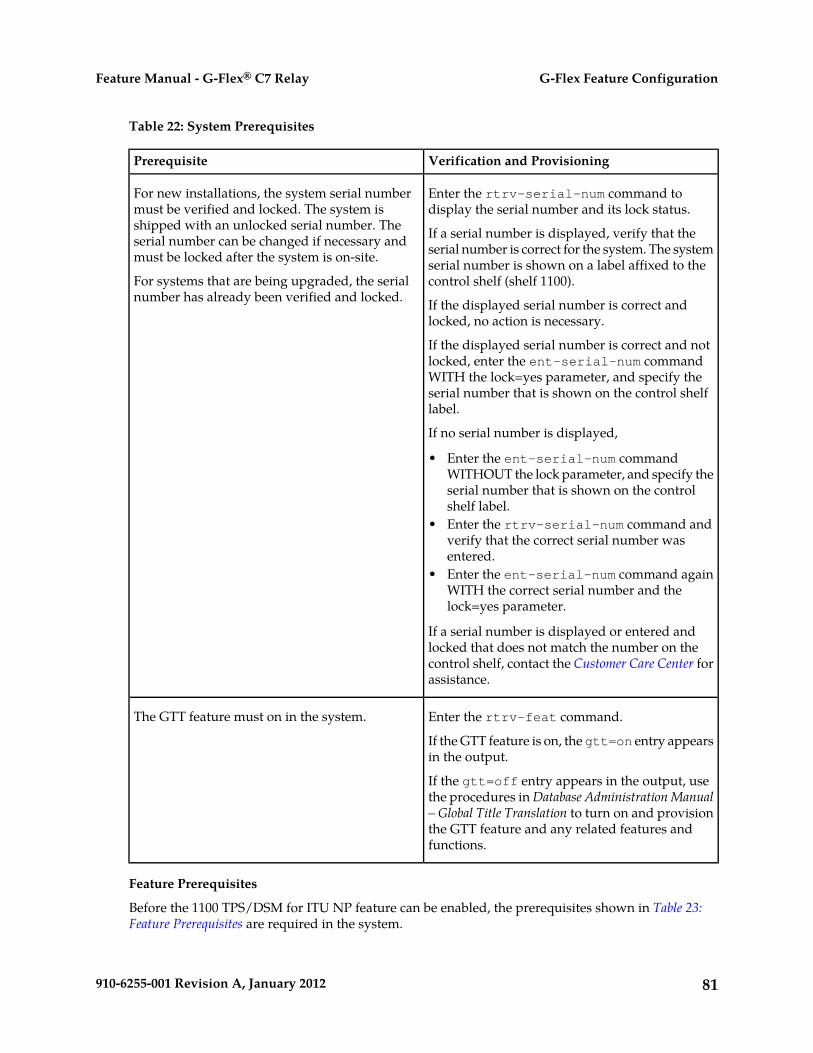
Table 22: System Prerequisites
Verification and ProvisioningPrerequisite
Enter the rtrv-serial-num command todisplay the serial number and its lock status.
For new installations, the system serial numbermust be verified and locked. The system isshipped with an unlocked serial number. The If a serial number is displayed, verify that the
serial number is correct for the system. The systemserial number can be changed if necessary andmust be locked after the system is on-site. serial number is shown on a label affixed to the
control shelf (shelf 1100).For systems that are being upgraded, the serialnumber has already been verified and locked. If the displayed serial number is correct and
locked, no action is necessary.
If the displayed serial number is correct and notlocked, enter the ent-serial-num commandWITH the lock=yes parameter, and specify theserial number that is shown on the control shelflabel.
If no serial number is displayed,
• Enter the ent-serial-num commandWITHOUT the lock parameter, and specify theserial number that is shown on the controlshelf label.
• Enter the rtrv-serial-num command andverify that the correct serial number wasentered.
• Enter the ent-serial-num command againWITH the correct serial number and thelock=yes parameter.
If a serial number is displayed or entered andlocked that does not match the number on thecontrol shelf, contact the Customer Care Center forassistance.
Enter the rtrv-feat command.The GTT feature must on in the system.
If the GTT feature is on, the gtt=on entry appearsin the output.
If the gtt=off entry appears in the output, usethe procedures in Database Administration Manual– Global Title Translation to turn on and provisionthe GTT feature and any related features andfunctions.
Feature Prerequisites
Before the 1100 TPS/DSM for ITU NP feature can be enabled, the prerequisites shown in Table 23:Feature Prerequisites are required in the system.
81910-6255-001 Revision A, January 2012
G-Flex Feature ConfigurationFeature Manual - G-Flex® C7 Relay
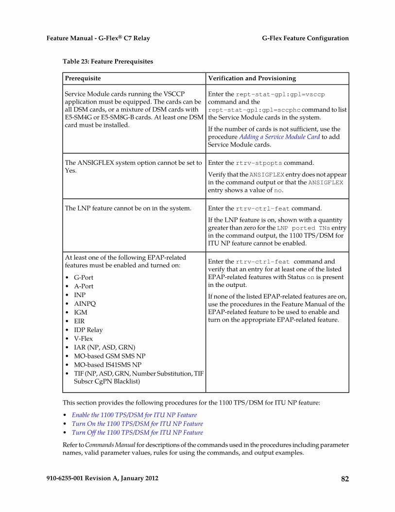
Table 23: Feature Prerequisites
Verification and ProvisioningPrerequisite
Enter the rept-stat-gpl:gpl=vsccpcommand and the
Service Module cards running the VSCCPapplication must be equipped. The cards can beall DSM cards, or a mixture of DSM cards with rept-stat-gpl:gpl=sccphc command to list
the Service Module cards in the system.E5-SM4G or E5-SM8G-B cards. At least one DSMcard must be installed. If the number of cards is not sufficient, use the
procedure Adding a Service Module Card to addService Module cards.
Enter the rtrv-stpopts command.The ANSIGFLEX system option cannot be set toYes. Verify that the ANSIGFLEX entry does not appear
in the command output or that the ANSIGFLEXentry shows a value of no.
Enter the rtrv-ctrl-feat command.The LNP feature cannot be on in the system.
If the LNP feature is on, shown with a quantitygreater than zero for the LNP ported TNs entryin the command output, the 1100 TPS/DSM forITU NP feature cannot be enabled.
Enter the rtrv-ctrl-feat command andverify that an entry for at least one of the listed
At least one of the following EPAP-relatedfeatures must be enabled and turned on:
EPAP-related features with Status on is presentin the output.
• G-Port• A-Port
If none of the listed EPAP-related features are on,use the procedures in the Feature Manual of the
• INP• AINPQ
EPAP-related feature to be used to enable andturn on the appropriate EPAP-related feature.
• IGM• EIR• IDP Relay• V-Flex• IAR (NP, ASD, GRN)• MO-based GSM SMS NP• MO-based IS41SMS NP• TIF (NP, ASD, GRN, Number Substitution, TIF
Subscr CgPN Blacklist)
This section provides the following procedures for the 1100 TPS/DSM for ITU NP feature:
• Enable the 1100 TPS/DSM for ITU NP Feature• Turn On the 1100 TPS/DSM for ITU NP Feature• Turn Off the 1100 TPS/DSM for ITU NP Feature
Refer to Commands Manual for descriptions of the commands used in the procedures including parameternames, valid parameter values, rules for using the commands, and output examples.
82910-6255-001 Revision A, January 2012
G-Flex Feature ConfigurationFeature Manual - G-Flex® C7 Relay

Enable the 1100 TPS/DSM for ITU NP Feature
This procedure is used to enable the 1100 TPS/DSM for ITU NP feature.
1. Enable the 1100 TPS/DSM for ITU NP feature with part number 893018001 and the feature accesskey.
enable-ctrl-feat:partnum=893018001:fak=<feature access key>
2. Verify the change by entering the rtrv-ctrl-feat command with the 1100 TPS/DSM for ITUNP feature part number 893018001.
rtrv-ctrl-feat:partnum=893018001
rlghncxa03w 09-08-24 21:15:37 EST EAGLE 40.1.0The following features have been permanently enabled: Feature Name Partnum Status Quantity HC-MIM SLK Capacity 893012707 on 64Prepaid SMS Intercept Ph1 893006701 on ----1100 TPS/DSM for ITU NP 893018001 off ---- ;
3. Back up the changes using the chg-db:action=backup:dest=fixed command.The following messages appear, the active Maintenance and Administration Subsystem Processor(MASP) appears first.BACKUP (FIXED) : MASP A - Backup starts on active MASP. BACKUP (FIXED) : MASP A - Backup on active MASP to fixed disk complete. BACKUP (FIXED) : MASP A - Backup starts on standby MASP. BACKUP (FIXED) : MASP A - Backup on standby MASP to fixed disk complete.
Turn On the 1100 TPS/DSM for ITU NP Feature
This procedure is used to turn on the 1100 TPS/DSM for ITU NP feature, after it has been enabled orturned off.
Note: If the EPAP-based traffic is higher than 70% of all traffic on the EAGLE 5 ISS, the DSM cardperformance may not reach 1100 TPS per DSM card.
1. Enter the chg-ctrl-feat command the first time and specify the 1100 TPS/DSM for ITU NPfeature part number 893018001and the status=on parameter value.
chg-ctrl-feat:partnum=893018001:status=on
The following message is displayed:CAUTION: Rated TPS for this feature supports an engineered GTTtraffic mix of no more than 70 percent EPAP-based traffic.Re-enter the command within 30 seconds to confirm change.
2. Re-enter the command the second time within 30 seconds to turn on the 1100 TPS/DSM for ITUNP feature.
chg-ctrl-feat:partnum=893018001:status=on
3. Verify the change by entering the rtrv-ctrl-feat command with the 1100 TPS/DSM for ITUNP feature part number.
83910-6255-001 Revision A, January 2012
G-Flex Feature ConfigurationFeature Manual - G-Flex® C7 Relay
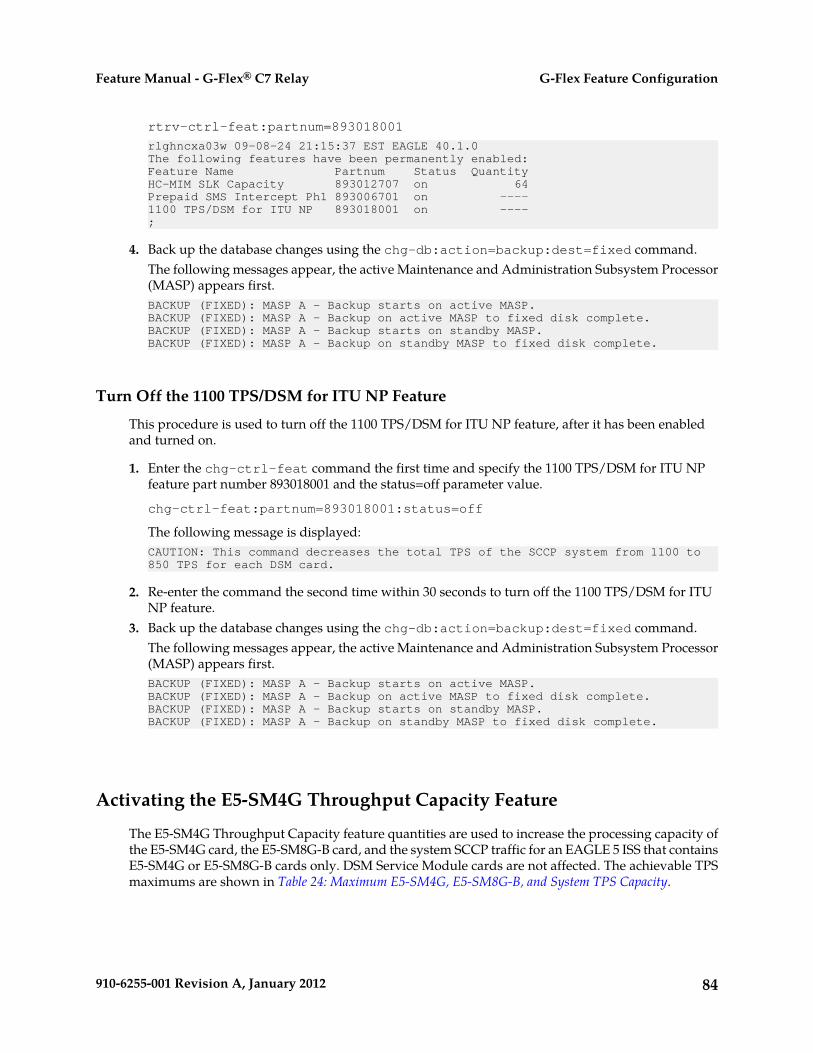
rtrv-ctrl-feat:partnum=893018001
rlghncxa03w 09-08-24 21:15:37 EST EAGLE 40.1.0The following features have been permanently enabled: Feature Name Partnum Status Quantity HC-MIM SLK Capacity 893012707 on 64Prepaid SMS Intercept Ph1 893006701 on ----1100 TPS/DSM for ITU NP 893018001 on ---- ;
4. Back up the database changes using the chg-db:action=backup:dest=fixed command.The following messages appear, the active Maintenance and Administration Subsystem Processor(MASP) appears first.BACKUP (FIXED): MASP A - Backup starts on active MASP.BACKUP (FIXED): MASP A - Backup on active MASP to fixed disk complete.BACKUP (FIXED): MASP A - Backup starts on standby MASP.BACKUP (FIXED): MASP A - Backup on standby MASP to fixed disk complete.
Turn Off the 1100 TPS/DSM for ITU NP Feature
This procedure is used to turn off the 1100 TPS/DSM for ITU NP feature, after it has been enabledand turned on.
1. Enter the chg-ctrl-feat command the first time and specify the 1100 TPS/DSM for ITU NPfeature part number 893018001 and the status=off parameter value.
chg-ctrl-feat:partnum=893018001:status=off
The following message is displayed:CAUTION: This command decreases the total TPS of the SCCP system from 1100 to 850 TPS for each DSM card.
2. Re-enter the command the second time within 30 seconds to turn off the 1100 TPS/DSM for ITUNP feature.
3. Back up the database changes using the chg-db:action=backup:dest=fixed command.The following messages appear, the active Maintenance and Administration Subsystem Processor(MASP) appears first.BACKUP (FIXED): MASP A - Backup starts on active MASP.BACKUP (FIXED): MASP A - Backup on active MASP to fixed disk complete.BACKUP (FIXED): MASP A - Backup starts on standby MASP.BACKUP (FIXED): MASP A - Backup on standby MASP to fixed disk complete.
Activating the E5-SM4G Throughput Capacity Feature
The E5-SM4G Throughput Capacity feature quantities are used to increase the processing capacity ofthe E5-SM4G card, the E5-SM8G-B card, and the system SCCP traffic for an EAGLE 5 ISS that containsE5-SM4G or E5-SM8G-B cards only. DSM Service Module cards are not affected. The achievable TPSmaximums are shown in Table 24: Maximum E5-SM4G, E5-SM8G-B, and System TPS Capacity.
84910-6255-001 Revision A, January 2012
G-Flex Feature ConfigurationFeature Manual - G-Flex® C7 Relay

Table 24: Maximum E5-SM4G, E5-SM8G-B, and System TPS Capacity
Maximum System TPS CapacityMaximum TPSCapacity perE5-SM8G -B Card
Maximum TPSCapacity perE5-SM4G Card
Feature QuantityPart Number
96,875 TPS with one or moreEPAP-related features and 31+1 cardswith EPAP running on T1200 AS
31253125893019101 - FeatureQuantity 5000
50005000 • 150,000 TPS with no EPAP-relatedor ELAP-related feature trafficand 31+1 cards
• 120,000 TPS with G-Flex and theANSIGFLEX STP option and 24+1cards
• 155,00 TPS with G-Flex and theANSIGFLEX STP option and 31+1cards with EPAP running onT1200 AS
• 40,000 TPS with ELAP and 8+1cards
• 85,000 TPS with ELAP and 17+1cards
68006800893019102 - FeatureQuantity 6800 • 210,800 TPS with no EPAP-related
or ELAP-related feature trafficand 31+1 cards
• 210,800 TPS with one or moreEPAP-related features and 31+1cards with EPAP running onT1200 AS
• 54,400 TPS with ELAP and 8+1cards
• 115,600 TPS with ELAP and 17+1cards
For E5-SM4G:100006800893019103 - FeatureQuantity 10000
• 210,800 TPS with no EPAP-relatedor ELAP-related feature trafficand 31+1 cards
• 210,800 TPS with one or moreEPAP-related features and 31+1cards with EPAP running onT1200 AS
• 54,400 TPS with ELAP and 8+1cards
85910-6255-001 Revision A, January 2012
G-Flex Feature ConfigurationFeature Manual - G-Flex® C7 Relay

Maximum System TPS CapacityMaximum TPSCapacity perE5-SM8G -B Card
Maximum TPSCapacity perE5-SM4G Card
Feature QuantityPart Number
• 115,600 TPS with ELAP and 17+1cards
For E5-SM8G-B:
• 310,000 TPS with no EPAP-relatedor ELAP-related feature trafficand 31+1 cards
• 310,000 TPS with one or moreEPAP-related features and 31+1cards with EPAP running onT1200 AS
• 80,000 TPS with ELAP and 8+1cards
• 170,000 TPS with ELAP and 17+1cards
An E5-SM4G Throughput Capacity quantity feature must be enabled using an E5-SM4G ThroughputCapacity feature part number (893019101, 893019102, or 893019102) and a feature access key.
The feature access key is based on the feature part number and the serial number of the EAGLE 5 ISS,making the feature access key site-specific.
Note: The E5-SM4G Throughput Capacity quantity feature must be purchased to receive the featureaccess key used to enable the feature. Contact your Tekelec Sales Representative or AccountRepresentative before beginning this procedure if you have purchased the E5-SM4G ThroughputCapacity quantity feature, but do not have the feature access key. A temporary feature access key isnot available for this feature.
After an E5-SM4G Throughput Capacity feature is enabled and turned on, the E5-SM4G ThroughputCapacity feature cannot be turned off. When the E5-SM4G Throughput Capacity feature is enabled,it is permanently enabled. The E5-SM4G Throughput Capacity feature cannot be temporarily enabled.
System Prerequisites
Before the E5-SM4G Throughput Capacity feature can be enabled, the prerequisites listed in Table 25:System Prerequisites are required in the system.
Table 25: System Prerequisites
Verification and ProvisioningPrerequisite
Enter the rtrv-serial-num command to display the serialnumber and its lock status.
For new installations, the system serialnumber must be verified and locked.The system is shipped with an unlocked Verify that the displayed serial number is correct for the
system. The serial number is shown on a label affixed to thecontrol shelf (shelf 1100).
serial number. The serial number canbe changed if necessary and must belocked after the system is on-site.
86910-6255-001 Revision A, January 2012
G-Flex Feature ConfigurationFeature Manual - G-Flex® C7 Relay
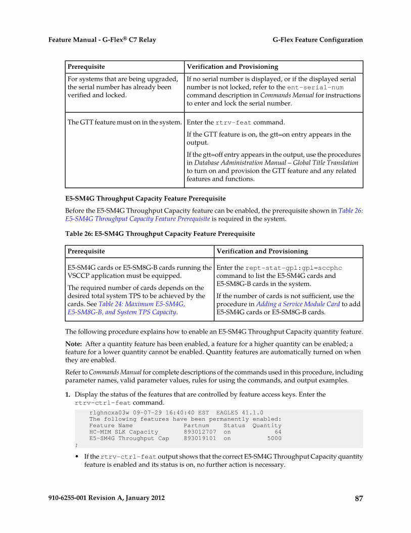
Verification and ProvisioningPrerequisite
If no serial number is displayed, or if the displayed serialnumber is not locked, refer to the ent-serial-num
For systems that are being upgraded,the serial number has already beenverified and locked. command description in Commands Manual for instructions
to enter and lock the serial number.
Enter the rtrv-feat command.The GTT feature must on in the system.
If the GTT feature is on, the gtt=on entry appears in theoutput.
If the gtt=off entry appears in the output, use the proceduresin Database Administration Manual – Global Title Translationto turn on and provision the GTT feature and any relatedfeatures and functions.
E5-SM4G Throughput Capacity Feature Prerequisite
Before the E5-SM4G Throughput Capacity feature can be enabled, the prerequisite shown in Table 26:E5-SM4G Throughput Capacity Feature Prerequisite is required in the system.
Table 26: E5-SM4G Throughput Capacity Feature Prerequisite
Verification and ProvisioningPrerequisite
Enter the rept-stat-gpl:gpl=sccphccommand to list the E5-SM4G cards andE5-SM8G-B cards in the system.
E5-SM4G cards or E5-SM8G-B cards running theVSCCP application must be equipped.
The required number of cards depends on thedesired total system TPS to be achieved by the If the number of cards is not sufficient, use the
procedure in Adding a Service Module Card to addE5-SM4G cards or E5-SM8G-B cards.
cards. See Table 24: Maximum E5-SM4G,E5-SM8G-B, and System TPS Capacity.
The following procedure explains how to enable an E5-SM4G Throughput Capacity quantity feature.
Note: After a quantity feature has been enabled, a feature for a higher quantity can be enabled; afeature for a lower quantity cannot be enabled. Quantity features are automatically turned on whenthey are enabled.
Refer to Commands Manual for complete descriptions of the commands used in this procedure, includingparameter names, valid parameter values, rules for using the commands, and output examples.
1. Display the status of the features that are controlled by feature access keys. Enter thertrv-ctrl-feat command. rlghncxa03w 09-07-29 16:40:40 EST EAGLE5 41.1.0 The following features have been permanently enabled: Feature Name Partnum Status Quantity HC-MIM SLK Capacity 893012707 on 64 E5-SM4G Throughput Cap 893019101 on 5000;
• If the rtrv-ctrl-feat output shows that the correct E5-SM4G Throughput Capacity quantityfeature is enabled and its status is on, no further action is necessary.
87910-6255-001 Revision A, January 2012
G-Flex Feature ConfigurationFeature Manual - G-Flex® C7 Relay

• If no E5-SM4G Throughput Capacity feature quantity is enabled or a higher quantity needs tobe enabled, continue with Step 2.
2. Enable the E5-SM4G Throughput Capacity quantity feature by entering the enable-ctrl-featcommand with the correct part number and FAK for the desired quantity.
3. Verify the status of the E5-SM4G Throughput Capacity quantity feature by entering thertrv-ctrl-feat command with the feature part number that was enabled (893033501, 893019102,or 893019103) in Step 2.rtrv-ctrl-feat:partnum=893019102
rlghncxa03w 09-08-29 16:40:40 EST EAGLE5 41.1.0 The following features have been permanently enabled: Feature Name Partnum Status Quantity HC-MIM SLK Capacity 893012707 on 64 E5-SM4G Throughput Cap 893019102 on 6800;
4. Back up the changes using the chg-db:action=backup:dest=fixed command.The following messages appear, the active Maintenance and Administration Subsystem Processor(MASP) appears first.BACKUP (FIXED): MASP A - Backup starts on active MASP.BACKUP (FIXED): MASP A - Backup on active MASP to fixed disk complete.BACKUP (FIXED): MASP A - Backup starts on standby MASP.BACKUP (FIXED): MASP A - Backup on standby MASP to fixed disk complete.
88910-6255-001 Revision A, January 2012
G-Flex Feature ConfigurationFeature Manual - G-Flex® C7 Relay

Chapter
6Measurements
This chapter describes the measurements that canbe collected and generated for the G-Flex feature,
Topics:
• G-Flex Measurements.....90 and the methods that can be used for generatingreports for G-Flex measurements.
89910-6255-001 Revision A, January 2012

G-Flex Measurements
The EAGLE 5 ISS Measurements system supports the collection and retrieval of measurements for heG-Flex features. The G-Flex measurements can be collected and reported with the following collectionmethods:
• OAM-based (UI) measurements collection - G-Flex measurements are available using the FileTransfer Area (FTA) and not directly to EAGLE 5 ISS UI terminals, when the E5-OAM IntegratedMeasurements feature is not on.
• The Measurements Platform feature enabled and the Measurements Platform collection option on• The E5-OAM Integrated Measurements feature enabled and on and the E5-OAM Integrated
Measurements collection option on
15 Minute Measurements can be used with the Measurements Platform or E5-OAM IntegratedMeasurements
Refer to the Measurements manual for for descriptions of collection methods, measurements, andmeasurements reports
Refer to the Commands Manual for descriptions of the commands used to enable and turn on features,turn on measurements collection options, and schedule and generate measurements reports.
Refer to the procedures in the Database Administration Manual - System Management to configure theMeasurements Platform feature or E5-OAM Integrated Measurements feature for use with G-Flex.
The G-Flex MSU measurements shown in Table 27: G-Flex MSU Measurements are supported for theG-Flex feature. No G-Flex measurements are counted when the G-Flex service is OFFLINE.
Table 27: G-Flex MSU Measurements
DescriptionEvent Name
G-Flex GTTs with Match – The total number of G-Flex Global Title Translationsuccessfully completed.
GFGTMATCH
G-Flex GTTs No Match – The total number of G-Flex Global Title Translationscompleted that did not match an entry in the RTDB.
GFGTNOMCH
G-Flex GTTs No Look-up – The total number of G-Flex Global Title Translationsthat could not be looked up in the RTDB because of some error.
GFGTNOLKUP
Note: This counter is not available using rept-meas by TT.
The measurement events shown in Table 28: STP Daily and Day-to-Hour Measurements that include Countsfor G-Flex MSUs are included in the STP Daily Maintenance (MTCD) and STP Day-to-Hour (MTCDTH)measurement reports and include peg counts for G-FLEX MSUs. These reports are similar to thoseused for GTT.
The existing GTT/SCCP measurements are used for both GTT and G-Flex and appear in the samereports. This implementation does not discriminate between the MSSCCPFL, GTTUN0NS, GTTUN1NT,
90910-6255-001 Revision A, January 2012
MeasurementsFeature Manual - G-Flex® C7 Relay

or GTTPERFD pegs for G-Flex or GTT applications. For example, a search failure could result from aproblem in either the RTDB or GTT database. G-Flex SCCP Service Re-Route Capability will count GTTmeasurements if GTT is performed.
Table 28: STP Daily and Day-to-Hour Measurements that include Counts for G-Flex MSUs
DescriptionEvent Name
MSUs discarded due to SCCP routing failure.MSSCCPFL
Also includes G-Flex MSUs that got a match from either the RTDB or GTTdatabase, but cannot be routed because of PC (Point Code) or SS (Subsystem)congestion, PC or SS unavailable, SS unequipped, or an unqualified error.
GTT unable to perform; no such type.GTTUN0NS
Also includes G-Flex GTT MSUs that did not match on new selectors (GTI, NP,NAI) in addition to ones not matching on TT.
GTT unable to perform: no translation on this address.GTTUN1NT
Also includes G-Flex MSUs that fell through to GTT, obtained a selector matchbut still did not get a match on the GTA.
Number of GTTs performed.GTTPERFD
Also includes G-Flex MSUs that got a match in either the RTDB or GTT database.
These measurements can also be used to determine the following:
• Total number of G-Flex MSUs: X = GFGTMATCH + GFGTNOMCH +GFGTNOLKUP
• Number of non-G-Flex GTT MSUs: GTTPERFD + GTTUN1NT +GTTUN0NS) - (X)
91910-6255-001 Revision A, January 2012
MeasurementsFeature Manual - G-Flex® C7 Relay

Chapter
7Maintenance
This chapter describes commands and reports thatcan be used for G-Flex maintenance, including statusreporting and problem identification.
Topics:
• G-Flex-Related Alarms.....93• G-Flex-Related UIMs.....93• Maintenance Commands.....95• Debug Commands.....97• Status Reporting and Problem Identification.....98
92910-6255-001 Revision A, January 2012

G-Flex-Related Alarms
Refer to the Unsolicited Alarm and Information Messages Manual for a complete description, formats,output examples, and the associated corrective procedure for each G-Flex-related UAM.
The alarms shown in Table 29: G-Flex-Related Alarms can be generated for the G-Flex service (includingG-Flex traffic).
Table 29: G-Flex-Related Alarms
Output Group
(UI Output Direction)Message TextSeverityUAM #
GTTSCCP is availableNone0328
GTTSCCP capacity normal, card(s) abnormalNone0329
GTTSCCP TPS Threshold exceededMajor0330
GTTSCCP is not availableCritical0331
GTTSCCP is removedNone0335
GTTLIM(s) have been denied SCCP serviceMajor0336
APSSService is availableNone0526
APSSService abnormalMinor0527
APSSService is not availableCritical0528
APSSService is disabledCritical0529
APSSService is removedNone0530
G-Flex-Related UIMs
The Unsolicited Alarm and Information Messages Manualcontains a complete description of all UIM textand formats. Table 30: G-Flex UIMs describes the G-Flex and G-Flex MLR UIMs. All of the theG-Flex-related UIMs are generated to the Application Subsystem Output Group.
93910-6255-001 Revision A, January 2012
MaintenanceFeature Manual - G-Flex® C7 Relay

Table 30: G-Flex UIMs
RecoveryDescriptionTextUIM #
Define the default CC bychg-stpopts:defcc=xxxx
Default CC is not definedConv to intlnum - Dflt CCnot found
1242
Define the default NDC bychg-stpopts:defndc=xxxx
Conversion to internationalnumber failed because defaultNDC was not found
Conv to intlnum - Dflt NCnot found
1243
Define the default MCC bychg-gsmopts:defmcc=xxxx
Default MCC is not definedConv to intlnum – Dflt MCCnot found
1244
Define the default MNC bychg-gsmopts:defmnc=xxxx
Default MNC is not definedConv to intlnum – Dflt MNCnot found
1245
Use an international number withlength within this range.
Length of the conditionedinternational number is <5 or>15
Invalid lengthof conditioneddigits
1246
Enter the E.212 part (MCC + MNC)for the E.214 MGT part (CC + NDC)
The E.212 part for the E.214MGT digit not found in thedatabase
Conversion ofMGT to IMSI notpossible
1247
in the database usingchg-gsmopts:ccndc=xxxxxx:mccmnc=yyyyyy
No action necessaryThe G-Flex MLR Functionencountered an
G-Flex MLR: Opwithout IMSIerroneous
1384
updateLocation,updateGprsLocation,sendAuthenticationInfo,registerSS, activateSS,deactivateSS, interrogateSS,restoreData, readyForSM, orpurgeMS operation that did notcontain an IMSI parameter
No action necessaryThe G-Flex MLR Functionencountered a sendParameters
G-Flex MLR: Opwithout IMSIskipped
1385
operation that did not containan IMSI parameter
94910-6255-001 Revision A, January 2012
MaintenanceFeature Manual - G-Flex® C7 Relay

RecoveryDescriptionTextUIM #
No action necessaryThe G-Flex MLR Functionencountered problems
G-Flex MLR: Opwith bad TCAPskipped
1386
decoding the TCAP and MAPlayers of a message prior toattempting to identify IMSI orMSISDN parameters (forexample, generic structuredecoding problems such asLength part errors). This UIMis not generated when a validTCAP component other thanInvoke is detected.
No action necessaryThe G-Flex MLR Functionencountered an IMSI parameter
G-Flex MLR: Opwith bad IMSIskipped
1387
that contains fewer than 5digits or more than 15 digits
No action necessaryThe G-Flex MLR Functionencountered an
G-Flex MLR: Opwith bad MSISDNskipped
1440
AnyTimeInterrogation,processUnstructuredSS-Request,or sendRoutingInfoForLCSoperation that contains aninvalid MSISDN parameter
No action necessaryThe G-Flex MLR Functionencountered a
G-Flex MLR: Opw/o IMSI/MSISDNskipped
1448
processUnstructuredSS-Requestoperation that does not containan IMSI or MSISDN parameter.
Maintenance Commands
The following commands can be used for maintenance when an EPAP-related feature is on.
Refer to Commands Manual for complete descriptions of the commands, including parameters, validparameter values, rules for using the commands, and output examples.
95910-6255-001 Revision A, January 2012
MaintenanceFeature Manual - G-Flex® C7 Relay
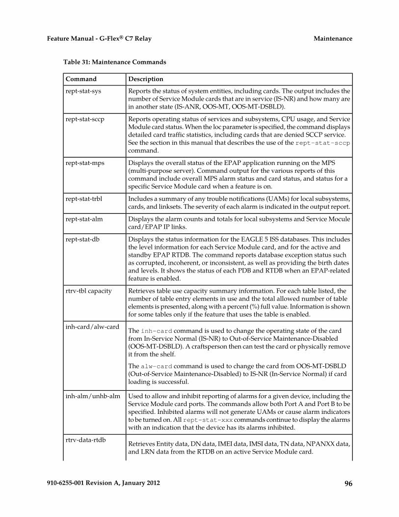
Table 31: Maintenance Commands
DescriptionCommand
Reports the status of system entities, including cards. The output includes thenumber of Service Module cards that are in service (IS-NR) and how many arein another state (IS-ANR, OOS-MT, OOS-MT-DSBLD).
rept-stat-sys
Reports operating status of services and subsystems, CPU usage, and ServiceModule card status. When the loc parameter is specified, the command displays
rept-stat-sccp
detailed card traffic statistics, including cards that are denied SCCP service.See the section in this manual that describes the use of the rept-stat-sccpcommand.
Displays the overall status of the EPAP application running on the MPS(multi-purpose server). Command output for the various reports of this
rept-stat-mps
command include overall MPS alarm status and card status, and status for aspecific Service Module card when a feature is on.
Includes a summary of any trouble notifications (UAMs) for local subsystems,cards, and linksets. The severity of each alarm is indicated in the output report.
rept-stat-trbl
Displays the alarm counts and totals for local subsystems and Service Moculecard/EPAP IP links.
rept-stat-alm
Displays the status information for the EAGLE 5 ISS databases. This includesthe level information for each Service Module card, and for the active and
rept-stat-db
standby EPAP RTDB. The command reports database exception status suchas corrupted, incoherent, or inconsistent, as well as providing the birth datesand levels. It shows the status of each PDB and RTDB when an EPAP-relatedfeature is enabled.
Retrieves table use capacity summary information. For each table listed, thenumber of table entry elements in use and the total allowed number of table
rtrv-tbl capacity
elements is presented, along with a percent (%) full value. Information is shownfor some tables only if the feature that uses the table is enabled.
The inh-card command is used to change the operating state of the cardfrom In-Service Normal (IS-NR) to Out-of-Service Maintenance-Disabled
inh-card/alw-card
(OOS-MT-DSBLD). A craftsperson then can test the card or physically removeit from the shelf.
The alw-card command is used to change the card from OOS-MT-DSBLD(Out-of-Service Maintenance-Disabled) to IS-NR (In-Service Normal) if cardloading is successful.
Used to allow and inhibit reporting of alarms for a given device, including theService Module card ports. The commands allow both Port A and Port B to be
inh-alm/unhb-alm
specified. Inhibited alarms will not generate UAMs or cause alarm indicatorsto be turned on. All rept-stat-xxx commands continue to display the alarmswith an indication that the device has its alarms inhibited.
Retrieves Entity data, DN data, IMEI data, IMSI data, TN data, NPANXX data,and LRN data from the RTDB on an active Service Module card.
rtrv-data-rtdb
96910-6255-001 Revision A, January 2012
MaintenanceFeature Manual - G-Flex® C7 Relay
DescriptionCommand
If the loc parameter is specified and the target card is an active Service Modulecard, the RTDB data is retrieved from that card.
If the loc parameter is not specified, the RTDB data is retrieved on the activeService Module card that has the lowest IMT address.
The RTDB status on the active Service Module card can be coherent orincoherent.
rept-stat-sccp
The rept-stat-sccp command provides statistics for Service Module cards and for the servicesthat execute on the cards. The statistics can be displayed for all Service Module cards, or for a specifiedcard.
Refer to the Commands Manual for a description of the rept-stat-sccp command, includingparameter names, valid values, and output examples for the command.
The rept-stat-sccp command displays the following statistics for the G-Flex service when theG-Flex feature is turned on:
• State information• Alarm information• Number of G-Flex messages that have been re-routed for the prior 30 seconds.
The Re-route count is incremented when the G-Flex service is OFFLINE and messages are re-routedto alternate PCs or fall through to GTT.
Debug Commands
The Commands Manual contains descriptions of debug commands that can be used in assessing andmodifying system status and operation. Most of the debug commands are used only under the directionof Tekelec support personnel.
Refer to the Commands Manual for a complete description of the debug commands, including theent-trace command.
A G-Flex MSU trigger can be created on the Service Module card, on any one or more of the followingcriteria defined in the ent-trace command. When multiple trigger criteria are entered, the MSU istrapped when any of the criteria are satisfied.
• E.164 MSISDN number (MSISDN) – Use this criterion to trap messages immediately beforeperforming a G-Flex search based on the MSISDN numbers defined in the Real Time Database(RTDB). This parameter allows a variable number of digits (from 5 to 15). The number specifiedmust be an International E.164 number (MSISDN or Entity Number).
• E.212 IMSI number (IMSI) – Use this criterion to trap messages immediately before performinga G-Flex search based on the IMSI numbers defined in the RTDB. This parameter allows a variablenumber of digits (from 5 to 15). The number specified must be an international E.212 IMSI. Thisparameter cannot be used to trap on E.214 MGT.
97910-6255-001 Revision A, January 2012
MaintenanceFeature Manual - G-Flex® C7 Relay
• Global Title digits (GT) – Use this criterion to trap messages based on the CdPA Global TitleAddress (that is, either E.164, E.214 MGT, or E.212 number) present in the SCCP part of the message.
• SSP point code (MSC or VLR PC, for example) – After the SSN has been determined to belong toa G-Flex entity object, use this criterion to trap messages based on CgPA (Calling Party Address)SPC present in the SCCP part of the message. If no point code is present in CgPA SPC, the criteriais matched with the OPC present in the MTP part of the message.
CAUTION: This command can cause the OAM card to reset if too many MSUs are trapped.
A trace must be set on all Service Module cards (card=sccp-all). A repetition parameter (rep) canbe used to control the number of MSUs that are trapped.
MSUs that satisfy any of the trigger criteria are trapped on the Service Module card are forwarded tothe OAM, and are displayed.
Status Reporting and Problem Identification
EAGLE 5 ISS commands can be used to obtain status and statistics for the EAGLE 5 ISS system, theEPAP systems, system devices including Service Module cards, EPAP-related features, local subsystems,and SCCP services.
Refer to the Commands Manual for complete descriptions of the commands, including parameters andvalid values, rules for using the commands correctly, and output examples.
Refer to the Unsolicited Alarm and Information Messages manual for descriptions and recovery proceduresfor UAMs and UIMs.
Refer to the EPAP Administration Manual for descriptions of EPAP functions and operation.
Refer to the EPAP Alarms on the T1200 Platform manual for descriptions and recovery procedures forEPAP alarms.
Refer to the appropriate Feature Manual for information about the functions and operation ofEPAP-related features.
Table 32: Status Reporting for EPAP-Related Features
CommandReports, Status, and Statistics
EAGLE 5 ISS
rept-stat-sysMaintenance Status Report - indicates whetherMaintenance, Routing, and SCCP Baselines havebeen established.
rept-stat-sysAlarms and operating state for system devices,including Service Module ( "SCCP") cards.
98910-6255-001 Revision A, January 2012
MaintenanceFeature Manual - G-Flex® C7 Relay
CommandReports, Status, and Statistics
rept-stat-almUnsolicited Alarm Messages (UAMs) andUnsolicited Information Messages (UIMs)
rept-stat-trbl
EPAP/MPS (from the EAGLE 5 ISS)
rept-stat-mpsEPAP code version and operating state for eachEPAP.
rept-stat-mpsMPS hexadecimal alarm strings for the active andstandby EPAPs.
rept-stat-mpsOperating state and alarm status of equippedService Module cards and their DSM ports andIP connections. rept-stat-mps:loc=<Service Module card location>
rept-stat-mps:loc=<Service Modulecard location>
Amount of memory used by the RTDB on thespecified card, as a percent of available ServiceModule card memory.
rept-stat-dbEPAP Provisioning Database (PDB), EPAP RealTime Database (RTDB), and Service Module card
rept-stat-db:db=mpsRTDB status information - Coherent, birthdate(date and time of creation), and exception(condition when a problem was detected).
Service Module Cards, EPAP-Related Features, Services, Local Subsystems
rept-stat-sccpStatus of the Service Module cards, and theservices executing on the cards for EPAP-relatedfeatures that are turned on. Includes ServiceReport, Subsystem Report, and Alarm Status;Total Service Statistics.
rept-stat-mps:loc=<Service Modulecard location>
Operating state and alarm status of equippedService Module cards and their DSM ports andIP connections; EPAP-related feature status percard.
rept-stat-sysAlarms and operating state for Service Module ("SCCP") cards.
rept-stat-mps
rept-stat-sccpAny cards that are denied SCCP service.
99910-6255-001 Revision A, January 2012
MaintenanceFeature Manual - G-Flex® C7 Relay

CommandReports, Status, and Statistics
rept-stat-sccp:loc=<Service Modulecard location>
Detailed view of the status of SCCP servicesprovided by the specified Service Module card.Includes Card Alarm Status, Card ServiceStatistics
rept-stat-sccp:mode=perfGeneral SCCP traffic performance for ServiceModule cards. Message rates for TVGperformance.
rept-stat-sccpStatistics for EPAP-related feature localsubsystems - Subsystem Report
rept-stat-sccpStatistics for EPAP-related features
EPAP Status and Alarm Reporting
Because EPAP has no direct means of accepting user input or displaying output messages on EAGLE5 ISS terminals, EPAP maintenance, measurements, and status information are routed through aService Module card. EPAP sends two types of messages to the Service Module card: EPAP MaintenanceBlocks and DSM Status Requests and DSM Status Messages. Each message type is discussed in thefollowing sections.
EPAP Maintenance Blocks
The EPAP forwards all status and error messages to the Service Module cards in maintenance blocks.Maintenance blocks are asynchronously sent whenever the EPAP has something to report. The statusinformation that is displayed when a rept-stat-mps command is issued includes information thatcame from the maintenance blocks.
The active EPAP generates and sends maintenance blocks to the primary Service Module card. Onemaintenance block is sent as soon as the IP link is established between the active EPAP and the primaryService Module card. Additional maintenance blocks are sent whenever the EPAP needs to report anychange in status or error conditions. The information returned in maintenance blocks is included inthe output of the rept-stat-mps and rept-stat-sccp commands.
The EPAP sends maintenance blocks that contain at least the following information:
• Status of EPAP 'A' - actual states are active, standby, and down (inoperative). Maintenance blocksinclude a field for this information so that it can be available for the output of the rept-stat-mpscommand.
• Status of EPAP 'B' - actual states are active, standby, and down (inoperative). Maintenance blocksinclude a field for this information so that it can be available for the output of the rept-stat-mpscommand.
• Identification of Active EPAP - a field to identify the active EPAP.• Congestion Indicator - an indicator showing provisioning link congestion. The link between the
EPAPs and the external source of provisioning data can become congested in high-provisioning
100910-6255-001 Revision A, January 2012
MaintenanceFeature Manual - G-Flex® C7 Relay
traffic situations. When this occurs and subsequently as the congestion clears, the EPAP sendsmaintenance blocks to the Service Module card.
• Alarm Conditions - an error code field. If the EPAP needs to report an alarm condition, it puts anappropriate UAM identifier in this field.
• Current MPS Database Size - a field indicating the current RTDB size. The Service Module carduses this information to calculate the percentage of memory used by the RTDB.
DSM Status Requests and DSM Status Messages
When the EPAP needs to know the status of a Service Module card, it sends a DSM Status Request toall Service Module cards, and each Service Module card returns its status to the EPAP.
Service Module cards send a DSM Status Message to the EPAP when any the following events occurin the Service Module card:
• The Service Module card is booted.• The Service Module card receives a DSM Status Request message from the EPAP• The Service Module card determines that it needs to download the entire RTDB; for example, the
Service Module card determines that the RTDB needs to be downloaded because it is totallycorrupted, or a craftsperson requests that the RTDB be reloaded. The Service Module card sendsa Full Download Request message to the EPAP
• The Service Module card starts receiving RTDB downloads or updates. When a Service Modulecard starts downloading the RTDB or accepting updates, it sends a DSM Status Message informingthe EPAP of the first record received. This helps the EPAP keep track of downloads in progress.
The DSM Status Message provides the following information to the EPAP:
• DSM Memory Size. When the Service Module card is initialized, it determines the amount ofmemory present. The EPAP uses the value to determine if the Service Module card has enoughmemory to hold the RTDB.
• Load Mode Status. This indicator indicates whether or not a sufficient number of the IS-NR(In-Service Normal) LIMs have access to SCCP services.
Hourly Maintenance Report
The Hourly Maintenance Report, generated automatically, includes the alarm totals of the G-Flexsubsystem and Service Module card /EPAP IP links. A sample follows.
eagle10506 99-10-10 16:00:01 EST EAGLE 37.5.0 5072.0000 REPT COND GSM SS "GSM SS :0440,MTCEINT-0,SA,99-10-10,16:00:01,,,,*C"; eagle10506 99-10-10 16:00:01 EST EAGLE 37.5.0 5073.0000 REPT COND INP SS "INP SS :0440,MTCEINT-0,SA,99-10-10,16:20:01,,,,*C"; eagle10506 99-10-10 16:00:01 EST EAGLE 37.5.0 5077.0000 REPT COND EPAPDSM "EPAPDSM :0084,MTCEINT-0,SA,99-10-10,16:00:01,,,,**"; eagle10506 99-10-10 16:00:01 EST EAGLE 37.5.0 5007.0000 REPT COND CARD "CARD 1102:0422,SCMMA,SA,99-10-10,16:00:01,,,,**"
101910-6255-001 Revision A, January 2012
MaintenanceFeature Manual - G-Flex® C7 Relay

; eagle10506 99-09-13 16:00:01 EST EAGLE 37.5.0 3561.0000 REPT COND ALARM STATUS "ALARMS:PERM. INHIBITED,0,0,0" "ALARMS:TEMP. INHIBITED,0,0,0" "ALARMS:ACTIVE,10,14,3" "ALARMS:TOTAL,10,14,3";
102910-6255-001 Revision A, January 2012
MaintenanceFeature Manual - G-Flex® C7 Relay

GlossaryA
American National StandardsInstitute
ANSI
An organization that administersand coordinates the U.S. voluntarystandardization and conformityassessment system. ANSI developsand publishes standards. ANSI isa non-commercial,non-government organizationwhich is funded by more than 1000corporations, professional bodies,and enterprises.
C
Country CodeCC
Called Party AddressCdPA
The field in the SCCP portion of theMSU that contains the additionaladdressing information of thedestination of the MSU. Gatewayscreening uses this additionalinformation to determine if MSUsthat contain the DPC in the routinglabel and the subsystem number inthe called party address portion ofthe MSU are allowed in the networkwhere the EAGLE 5 ISS is located.
Capability Point CodeCPC
A capability point code used by theSS7 protocol to identify a group offunctionally related STPs in thesignaling network.
D
Device Control BlockDCB
103910-6255-001 Revision A, January 2012

D
Directory numberDN
A DN can refer to any mobile orwireline subscriber number, and caninclude MSISDN, MDN, MIN, or thewireline Dialed Number.
Destination Point CodeDPC
DPC refers to the scheme in SS7signaling to identify the receivingsignaling point. In the SS7 network,the point codes are numericaddresses which uniquely identifyeach signaling point. This point codecan be adjacent to the EAGLE 5 ISS,but does not have to be.
Database Service Module.DSM
The DSM provides large capacitySCCP/database functionality. TheDSM is an application card thatsupports network specific functionssuch as EAGLE ProvisioningApplication Processor (EPAP),Global System for MobileCommunications (GSM), EAGLELocal Number Portability (ELAP),and interface to Local ServiceManagement System (LSMS).
E
EAGLE Provisioning ApplicationProcessor
EPAP
Features that require EPAPconnection and use the Real Time
EPAP-related features
Database (RTDB) for lookup ofsubscriber information.
• ANSI Number Portability Query(AINPQ)
• ANSI-41 AnalyzedInformationQuery – no EPAP/ELAP(ANSI41 AIQ)
104910-6255-001 Revision A, January 2012
GlossaryFeature Manual - G-Flex® C7 Relay
E
• Anytime Interrogation NumberPortability (ATI NumberPortability, ATINP)
• AINPQ, INP, G-Port SRI Queryfor Prepaid, GSM MAP SRIRedirect, IGM, and ATINPSupport for ROP
• A-Port Circular Route Prevention(A-Port CRP)
• Equipment Identity Register(EIR)
• G-Flex C7 Relay (G-Flex)• G-Flex MAP Layer Routing
(G-Flex MLR)• G-Port SRI Query for Prepaid• GSM MAP SRI Redirect to
Serving HLR (GSM MAP SRIRedirect)
• GSM Number Portability(G-Port)
• IDP A-Party Blacklist• IDP A-Party Routing• IDP Relay Additional Subscriber
Data (IDPR ASD)• IDP Relay Generic Routing
Number (IDPR GRN)• IDP Service Key Routing (IDP SK
Routing)• IDP Screening for Prepaid• INAP-based Number Portability
(INP)• Info Analyzed Relay Additional
Subscriber Data (IAR ASD)• Info Analyzed Relay Base (IAR
Base)• Info Analyzed Relay Generic
Routing Number (IAR GRN)• Info Analyzed Relay Number
Portability (IAR NP)• INP Circular Route Prevention
(INP CRP)• IS41 Mobile Number Portability
(A-Port)• IS41 GSM Migration (IGM)• MNP Circular Route Prevention
(MNPCRP)
105910-6255-001 Revision A, January 2012
GlossaryFeature Manual - G-Flex® C7 Relay

E
• MO-based GSM SMS NP• MO-based IS41 SMS NP• MO SMS Generic Routing
Number (MO SMS GRN)• MO- SMS B-Party Routing• MO SMS IS41-to-GSM Migration• MT-based GSM SMS NP• MT-based GSM MMS NP• MT-based IS41 SMS NP• MTP Routed Messages for SCCP
Applications (MTP Msgs forSCCP Apps)
• MTP Routed Gateway ScreeningStop Action (MTPRTD GWS StopAction)
• Portability Check for MO SMS• Prepaid IDP Query Relay (IDP
Relay, IDPR)• Prepaid SMS Intercept Phase 1
(PPSMS)• Service Portability (S-Port)• S-Port Subscriber Differentiation• Triggerless ISUP Framework
Additional Subscriber Data (TIFASD)
• Triggerless ISUP FrameworkGeneric Routing Number (TIFGRN)
• Triggerless ISUP NumberPortability (TIF NP)
• Triggerless ISUP FrameworkNumber Substitution (TIF NS)
• Triggerless ISUP Framework SCSForwarding (TIF SCSForwarding)
• Triggerless ISUP FrameworkSimple Number Substitution (TIFSNS)
• Voice Mail Router (V-Flex)
The shelves in the EAGLE 5 ISS thatcontain cards other than control
ES
cards (E5-OAM, GPSM-II for OAM,TDM, and MDAL cards). This shelfcan be added to and removed from
106910-6255-001 Revision A, January 2012
GlossaryFeature Manual - G-Flex® C7 Relay

E
the database. These shelves arenumbered from 1200 to 6100.
F
File Transfer AreaFTA
A special area that exists on eachOAM hard disk, used as a stagingarea to copy files to and from theEAGLE 5 ISS using the Kermitfile-transfer protocol.
G
GSM Flexible numberingG-Flex
A feature that allows the operator toflexibly assign individual subscribersacross multiple HLRs and routesignaling messages, based onsubscriber numbering, accordingly.
Global System for MobileCommunications
GSM
Global Title AddressGTA
Global Title Address InformationGTAI
Global Title TranslationGTT
A feature of the signaling connectioncontrol part (SCCP) of the SS7protocol that the EAGLE 5 ISS usesto determine which service databaseto send the query message when anMSU enters the EAGLE 5 ISS andmore information is needed to routethe MSU. These service databasesalso verify calling card numbers andcredit card numbers. The servicedatabases are identified in the SS7network by a point code and asubsystem number.
107910-6255-001 Revision A, January 2012
GlossaryFeature Manual - G-Flex® C7 Relay

G
Graphical User InterfaceGUI
The term given to that set of itemsand facilities which provide theuser with a graphic means formanipulating screen data ratherthan being limited to characterbased commands.
H
Home Location RegisterHLR
I
Initial Address MessageIAM
International Mobile SubscriberIdentity
IMSI
Internet ProtocolIP
IP specifies the format of packets,also called datagrams, and theaddressing scheme. The networklayer for the TCP/IP protocol suitewidely used on Ethernet networks,defined in STD 5, RFC 791. IP is aconnectionless, best-effort packetswitching protocol. It providespacket routing, fragmentation andre-assembly through the data linklayer.
Integrated Signaling SystemISS
International TelecommunicationsUnion
ITU
L
Signaling LinkLink
Signaling Link
Carries signaling within a Link Setusing a specific Association. A Link
108910-6255-001 Revision A, January 2012
GlossaryFeature Manual - G-Flex® C7 Relay
L
can belong to only one Link Set andone Association. There is generallyone Link per Association in a LinkSet.
Local Number PortabilityLNP
M
Mobile Application PartMAP
Mobile Country CodeMCC
A three-digit number that uniquelyidentifies a country served bywireless telephone networks. TheMCC is part of the InternationalMobile Subscriber Identity (IMSI)number, which uniquely identifiesa particular subscriber. See alsoMNC, IMSI.
Mobile Dialed NumberMDN
Mobile Directory Number
Message Flow ControlMFC
Mobile Global TitleMGT
Mobile Identification NumberMIN
Mobile Network CodeMNC
A number that identifies a mobilephone carrier. Used in combinationwith a Mobile Country Code (MCC)to uniquely identify a mobile phoneoperator/carrier. See also MCC.
Mobile Number PortabilityMNP
109910-6255-001 Revision A, January 2012
GlossaryFeature Manual - G-Flex® C7 Relay
M
Multi-Purpose ServerMPS
The Multi-Purpose Server providesdatabase/reload functionality and avariety of high capacity/high speedoffboard database functions forapplications. The MPS resides in theGeneral Purpose Frame.
Messages Per Second
A measure of a message processor’sperformance capacity. A message isany Diameter message (Request orAnswer) which is received andprocessed by a message processor.
Mobile Station InternationalSubscriber Directory Number
MSISDN
The MSISDN is the network specificsubscriber number of a mobilecommunications subscriber. This isnormally the phone number that isused to reach the subscriber.
Message Signal UnitMSU
The SS7 message that is sent betweensignaling points in the SS7 networkwith the necessary information toget the message to its destinationand allow the signaling points in thenetwork to set up either a voice ordata connection between themselves.The message contains the followinginformation:
• The forward and backwardsequence numbers assigned tothe message which indicate theposition of the message in thetraffic stream in relation to theother messages.
• The length indicator whichindicates the number of bytes themessage contains.
• The type of message and thepriority of the message in the
110910-6255-001 Revision A, January 2012
GlossaryFeature Manual - G-Flex® C7 Relay
M
signaling information octet of themessage.
• The routing information for themessage, shown in the routinglabel of the message, with theidentification of the node thatsent message (originating pointcode), the identification of thenode receiving the message(destination point code), and thesignaling link selector which theEAGLE 5 ISS uses to pick whichlink set and signaling link to useto route the message.
Message Transfer PartMTP
The levels 1, 2, and 3 of the SS7protocol that control all the functionsnecessary to route an SS7 MSUthrough the network
Message Transfer Part, Level 3MTP3
N
Nature of Address IndicatorNAI
Standard method of identifyingusers who request access to anetwork.
Network Access Identifier
Network ClusterNC
Network Code
Not Compliant
Number PlanNP
O
Operations, Administration, andMaintenance
OAM
111910-6255-001 Revision A, January 2012
GlossaryFeature Manual - G-Flex® C7 Relay

O
The application that operates theMaintenance and AdministrationSubsystem which controls theoperation of many Tekelec products.
Originating Point CodeOPC
Operator Provisioning SystemOPS
P
Provisioning DatabasePDB
Provisioning Database ApplicationPDBA
There are two Provisioning DatabaseApplications (PDBAs), one in EPAPA on each EAGLE 5 ISS. They followan Active/Standby model. Theseprocesses are responsible forupdating and maintaining theProvisioning Database (PDB).
Provisioning Database InterfacePDBI
The interface consists of thedefinition of provisioning messagesonly. The customer must write aclient application that uses the PDBIrequest/response messages tocommunicate with the PDBA.
Point-to-Point ProtocolPPP
R
Request for CommentRFC
RFCs are standards-trackdocuments, which are officialspecifications of the Internet protocolsuite defined by the InternetEngineering Task Force (IETF) andits steering group the IESG.
112910-6255-001 Revision A, January 2012
GlossaryFeature Manual - G-Flex® C7 Relay

R
Reliable Multicast TransportProtocol
RMTP
Routing NumberRN
A signaling path from an LSP to anRSP using a specified Link Set
Route
Remote Signaling PointRSP
Represents an SS7 network node(point code) that signaling must besent to. An RSP has an SS7 domain(ANSI, ITUI, ITUN), a point code,and an optional Adjacent ServerGroup.
Remote Signaling Point
A logical element that represents aunique point code within aparticular SS7 domain with whichthe SS7 application's Local SignalingPoint interacts.
Reset RequestRSR
Route Set Test – Restricted message
Real Time DatabaseRTDB
S
Signaling Connection Control PartSCCP
DSM, E5-SM4G, or E5-SM8G-Bcard that contains the Real Time
Service Module card
Database (RTDB) downloadedfrom an EPAP or ELAP system.
See SNAI.Service Nature of Address Indicator
113910-6255-001 Revision A, January 2012
GlossaryFeature Manual - G-Flex® C7 Relay

S
Subscriber Identity ModuleSIM
An ID card the size of a credit cardfor GSM network subscribers, andis typically referred to as a chipcard or smartcard.
Service Information Octet.SIO
The network indicator code (NIC),priority (PRI), and service indicator(SI) in the SIO field in the messagesignaling unit (MSU). Thisinformation identifies the type ofMSU (ISUP, TCAP, and so forth) thatis allowed in the network where theEAGLE 5 ISS is located.
Signaling PointSP
A set of signaling equipmentrepresented by a unique point codewithin an SS7 domain.
Secondary Point CodeSPC
The SPC enables the EAGLE 5 ISS toassume more than one point codefor SS7 routing. The EAGLE 5 ISSuses the SPC for routing andprovisioning as if the SPC were anactual point code of the EAGLE 5ISS. The EAGLE 5 ISS supports oneANSI true point code and up toseven secondary point codes.
Spare Point Code
Send_Route_Information MessageSRI
Signaling System #7SS7
Subsystem NumberSSN
The subsystem number of a givenpoint code. The subsystem number
114910-6255-001 Revision A, January 2012
GlossaryFeature Manual - G-Flex® C7 Relay
S
identifies the SCP application thatshould receive the message, or thesubsystem number of the destinationpoint code to be assigned to the LNPsubsystem of the EAGLE 5 ISS.
A value of the routing indicatorportion of the global title translationdata commands indicating that nofurther global title translation isrequired for the specified entry.
Subsystem Number
Used to update the CdPA.
Signal Transfer PointSTP
The STP is a special high-speedswitch for signaling messages in SS7networks. The STP routes core INAPcommunication between the ServiceSwitching Point (SSP) and theService Control Point (SCP) over thenetwork.
See SSN.Subsystem Number
T
Transfer Control ProtocolTCP
Transmission ControlProtocol/Internet Protocol
TCP/IP
Translation Type.TT
Resides in the Called Party Address(CdPA) field of the MSU anddetermines which service databaseis to receive query messages. Thetranslation type indicates whichGlobal Title Translation tabledetermines the routing to aparticular service database.
115910-6255-001 Revision A, January 2012
GlossaryFeature Manual - G-Flex® C7 Relay

T
Group Ticket VoucherTVG
U
Unsolicited Alarm MessageUAM
A message sent to a user interfacewhenever there is a fault that isservice-affecting or when a previousproblem is corrected. Each messagehas a trouble code and textassociated with the troublecondition.
User Datagram ProtocolUDP
Unitdata Transfer ServiceUDTS
An error response to a UDTmessage.
Unsolicited Information MessageUIM
A message sent to a user interfacewhenever there is a fault that is notservice-affecting or when a previousproblem is corrected. Each messagehas a trouble code and textassociated with the troublecondition.
User Part UnavailableUPU
An MTP3 management message.
V
VxWorks Signaling ConnectionControl Part
VSCCP
The application used by the ServiceModule card to supportEPAP-related features and LNPfeatures. If an EPAP-related or LNPfeature is not turned on, and aService Module card is present, the
116910-6255-001 Revision A, January 2012
GlossaryFeature Manual - G-Flex® C7 Relay

V
VSCCP application processes normalGTT traffic.
117910-6255-001 Revision A, January 2012
GlossaryFeature Manual - G-Flex® C7 Relay