features - telematic.com ld300... · •0.04% high accuracy • ±0.2% of url stability - guarantee...
TRANSCRIPT

• ± 0.04% High Accuracy
• ±0.2% of URL Stability - Guarantee for 12 Years
• 120:1 Rangeability
• Non-volatile Totalizer
• Tank Linearization
• 100 ms Total Response Time
• PID Control Capability
• Bi-directional Flow Measurement
• Advanced Diagnostics
• Largest Library of Function
• Instantiable Function Blocks
• Supported by DD, EDDL and FDT/DTM
• Three Technology Options

2
Features
FoundationtM fieldbus
± 0.04% high performance option;± 0.2% of URL stability;120:1 rangeability;Span as small as 50 Pa (0.2 inH2O) up to a range limit of 40 MPa (5800 psi);Up to 52 MPa static pressure (7500 psi);Direct digital capacitance sensing (no A/D conversion);True non-interactive zero and span;Local zero and span adjustment;Remote calibration and parameterization;Transfer functions: linear, V x, V x3 e V x5 ;Tank linearization;Alphanumerical LCD indication;Small and lightweight;Explosion proof and weather proof housing approved (IP66/68 or IP66/68W);Intrinsically safe certification;Signal simulation for loop tests;Non-volatile flow totalization;Configurable user unit;Configurable local adjustment;EMC (Electromagnetic Compatibility) according to IEC61326-1:2006, IEC61326-2-3:2006, IEC61000-6-4:2006, IEC61000-6-2:2005;Write protection function;Three technology options: HART®, FoundationTM fieldbus, PROFIBUS PA.
Update output current in 100 ms with 0.75 μA resolution;Improved performance due to dedicated math co-processor;Multidrop operation mode;PID control function;Supports DTM and EDDL;Bi-directional flow measurement;With FMEDA analysis and MTBF of 244 years.
17 different types of function blocks for control strategies and advanced diagnostics;Up to 20 function blocks;Execution of up to 29 external links;12 mA consumption;Dynamic block instantiation improves interchangeability;Fieldbus FoundationTM registered and ITK approved;MVC (Multivariable Container) enabled;MTBF of 186 years.
12 mA consumption;Function blocks for analog input and totalization;Integrated to Smar ProfibusView or Simatic PDM;Supports DTM and EDDL;Profile 3.0 improves interchangeability;MTBF of 186 years.
HART® - 4 to 20 mA
PROFIBUS PA

3
Functional Description
Sensing Diaphragm (1)Isolating Diaphragm (2)
Filling Fluid (3)Ceramics
Metalized Surface (4)GlassSteel
LD300 Series offers: ± 0.04% accuracy for high performance option; ± 0.2% of URL stability guarantee for 12 Years; 120:1 rangeability; Compact and lightweight; Multiple Protocol Options.
LD300 Series uses the field-proven technique of capacitance cell sensor measurement.
The sensor is shown in the picture above. The sensing diaphragm (1) is at the cell center. The diaphragm deflects as a result of the difference between the pressures applied to the left and right sides of the sensor. Pressure is directly applied to the isolating diaphragms (2), which provide resistance against process fluid corrosion. The pressure is transmitted to the sensing diaphragm through the filling fluid (3).
The sensing diaphragm is a moving capacitor plate while the two metallized surfaces (4) are fixed plates. The sensing diaphragm deflection results in capacitance variations between the moving and fixed plates.
The electronic resonance circuit reads capacitance variation between the moving and fixed plates. The CPU conditions the measurement and communicates according to protocol. As there is no A/D conversion, errors and drifts during conversions are eliminated. A temperature sensorprovides temperature compensations, which combined with the sensor precision, results in high accuracy and rangeability for the LD300 Series.
The process variable, as well as monitoring and diagnostics information, are provided by digital communication protocol.The available protocol options are: HART®, FoundationTM fieldbus and PROFIBUS PA.
These protocols are easily changed by either replacing the internal electronic board or downloading the firmware. AHART® transmitter can be changed into a FoundationTM fieldbus / PROFIBUS PA device by replacing the internal card, and vice versa. A FoundationTM fieldbus device can be changed into a PROFIBUS PA device and vice versa, by simply downloading a new firmware.
Sensor Main Board

4
Transmitter Types
Sanitary Transmitter
Differential Pressure - LD300D and LD300HPressure is applied to high and low sides and differential pressure is measured. High static pressure is supported by LD300H models.
Flow - LD300D and LD300HThe differential pressure is generated by a primary flow element and the square root function computes the flow measurement.
Absolute Pressure - LD300AThe pressure is measured at the high side of the transmitter and the low side is at zero absolute reference to a sealed chamber with vaccum.
Gage Pressure - LD300MThe pressure is measured at the high side of the transmitter and the low side is open to the atmosphere, providing true local atmospheric reference.
Level - LD300LThe transmitter has a flange mounted unit for direct installation on vessels. Extended diaphragms are also available. For closed tank low side can compensate for ullage pressure.
SR301 is a remote seal designed for chemical and thermal isolation. LD300 Series can be assembled with separatediaphragm seals in either one or both sides of the sensor. SR301 options include: “T” Type Flanged (SR301T), Threaded (SR301R), Pancake (SR301P) where those three models with an optional flush connection, Sanitary (SR301S), Flanged with Extension (SR301E) and Pancake with Extension (SR301Q).The flush connection enables deposits removal without disconnecting the seal.Typical applications for LD300 Series with remote seals: Corrosive process fluid; Suspended solids or viscous process fluid; Process fluids that may freeze or solidify; Process temperatures higher than supported by transmitters; Replaces impulse lines and condensate legs; Bubble system.See the Smar SR301 Series catalog for further information regarding application and specification.
LD300S Series are specially designed for food and other applications where sanitary connections are required. With threaded or “tri-clamp” connections, it allows for easy and quick maintenance and cleaning. Tri-clamp and other connections are compliant to 3A-7403 standard for food grade applications.For further information, see the Smar SR301 Series Catalog.
Remote Seals
Manifold Valves
Smar manifold valves provide all of the necessary safety for field maintenance of LD300 Series transmitters. Working at pressures up to 6,000 psi, they are easy to handle and lighter than others in the market. Pressure and leakage tests carried out in 100% of the valves, also for models mounted on the transmitter. For further information, please see the Smar Manifold Valves Catalog.
5
Parameterization and Diagnostics
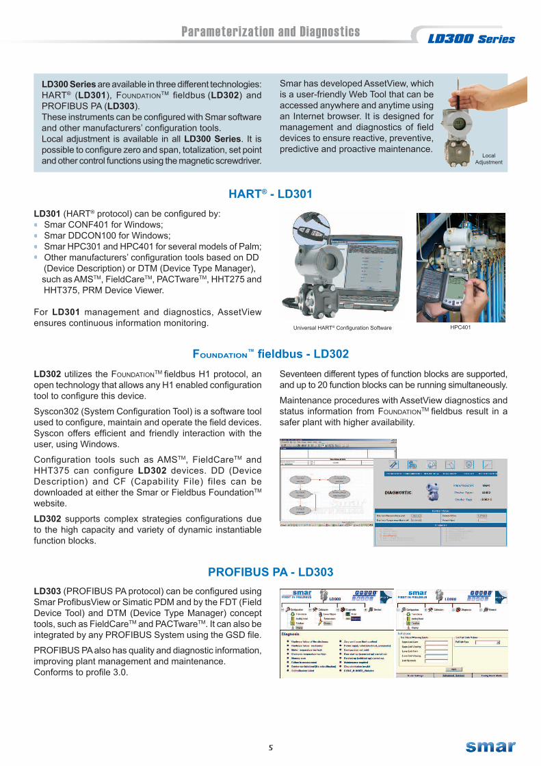
LD300 Series are available in three different technologies:HART® (LD301), FoundationTM fieldbus (LD302) and PROFIBUS PA (LD303).These instruments can be configured with Smar softwareand other manufacturers’ configuration tools.Local adjustment is available in all LD300 Series. It is possible to configure zero and span, totalization, set point and other control functions using the magnetic screwdriver.
LD301 (HART® protocol) can be configured by: Smar CONF401 for Windows; Smar DDCON100 for Windows; Smar HPC301 and HPC401 for several models of Palm; Other manufacturers’ configuration tools based on DD (Device Description) or DTM (Device Type Manager), such as AMSTM, FieldCareTM, PACTwareTM, HHT275 and HHT375, PRM Device Viewer.
For LD301 management and diagnostics, AssetView ensures continuous information monitoring.
HART® - LD301
Universal HART® Configuration Software HPC401
LD302 utilizes the FoundationTM fieldbus H1 protocol, an open technology that allows any H1 enabled configuration tool to configure this device.
Syscon302 (System Configuration Tool) is a software tool used to configure, maintain and operate the field devices. Syscon offers efficient and friendly interaction with the user, using Windows.
Configuration tools such as AMSTM, FieldCareTM and HHT375 can configure LD302 devices. DD (Device Description) and CF (Capability File) files can be downloaded at either the Smar or Fieldbus FoundationTM website.
LD302 supports complex strategies configurations due to the high capacity and variety of dynamic instantiable function blocks.
Foundation™ fieldbus - LD302
LD303 (PROFIBUS PA protocol) can be configured using Smar ProfibusView or Simatic PDM and by the FDT (Field Device Tool) and DTM (Device Type Manager) concept tools, such as FieldCareTM and PACTwareTM. It can also be integrated by any PROFIBUS System using the GSD file.
PROFIBUS PA also has quality and diagnostic information, improving plant management and maintenance.Conforms to profile 3.0.
PROFIBUS PA - LD303
Seventeen different types of function blocks are supported, and up to 20 function blocks can be running simultaneously.
Maintenance procedures with AssetView diagnostics and status information from FoundationTM fieldbus result in a safer plant with higher availability.
Smar has developed AssetView, which is a user-friendly Web Tool that can be accessed anywhere and anytime using an Internet browser. It is designed for management and diagnostics of field devices to ensure reactive, preventive, predictive and proactive maintenance.
LocalAdjustment
6
Applications
LD302LT
LD302PT FY302
FVLD302FT
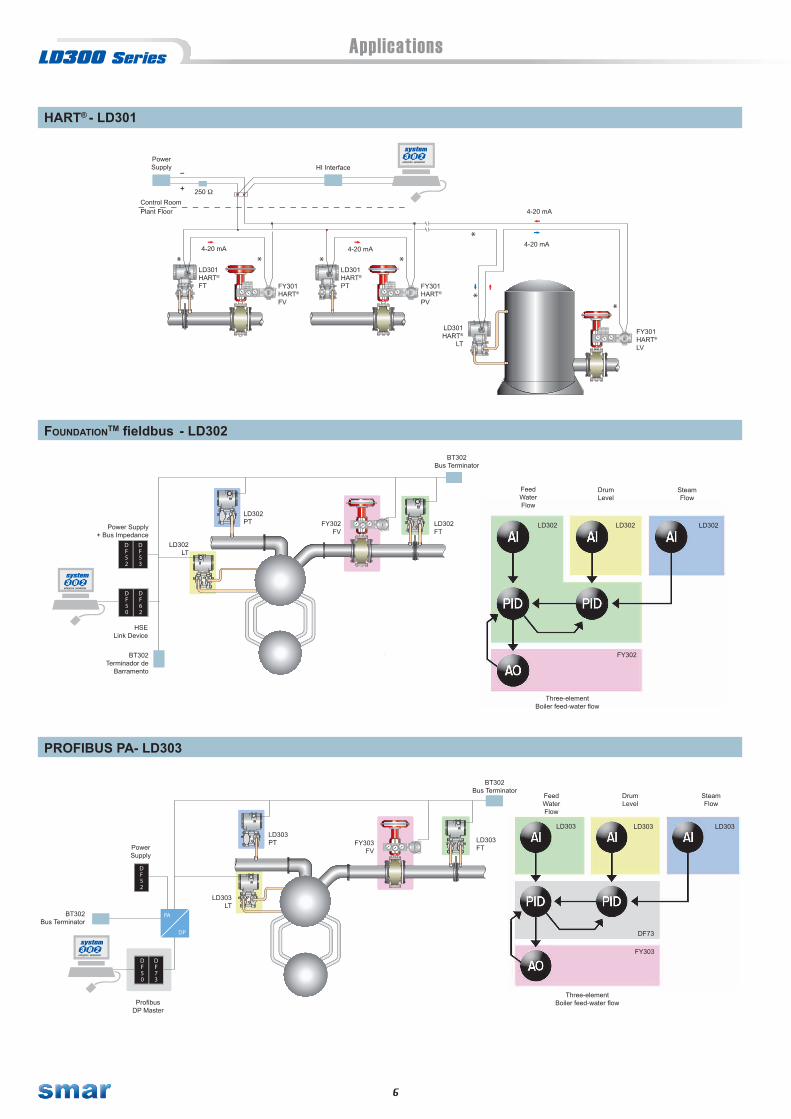
HART® - LD301
FoundationtM fieldbus - LD302
PROFIBUS PA- LD303
FeedWaterFlow
LD302 LD302LD302
FY302
DrumLevel
SteamFlow
FeedWaterFlow
LD303 LD303
FY303
DrumLevel
SteamFlow
Three-elementBoiler feed-water flow
DF73
LD303
LD303FT
FY303FV
LD303PT
LD303LT
BT302Terminador de
Barramento
BT302Bus Terminator
HSELink Device
Power Supply+ Bus Impedance
ProfibusDP Master
PowerSupply
BT302Bus Terminator
BT302Bus Terminator
Three-elementBoiler feed-water flow
TCU OM
IH
ON IG S
E
DO
AE DN
P-
AAH
O
OMTRE AO
EM
ANEFS AR
N DIUC
T
C EK
IPETUA
T
ILO G
NEEPX R
DZAS
AIV
EREV
EAL H
IP
A IN- EL
WE
T HX P
CVI
NOS
I RE
TT
CU OMIH
ON IG S
E
DO
AE DN
P-
AAH
O
OMTRE AO
EM
ANEFS AR
N DIUC
T
C EK
IPETUA
T
ILO G
NEEPX R
DZAS
AIV
EREV
EAL H
IP
A IN- EL
WE
T HX P
CVI
NOS
I RE
T
TCU OM
IH
ON IG S
E
DO
AE DN
P-
AAH
O
OMTRE AO
EM
ANEFS AR
N DIUC
T
C EK
IPETUA
T
ILO G
NEEPX R
DZAS
AIV
EREV
EAL H
IP
A IN- EL
WE
T HX P
CVI
NOS
I RE
T
4-20 mA4-20 mA
FY301 HART®
PV
LD301HART®
PT
Control Room
HI Interface
FY301 HART®
LV
LD301HART®
LT
4-20 mAPlant Floor
4-20 mA
FY301 HART®
FV
LD301HART®
FT
PowerSupply
250
7
Technical Characteristics
Functional Specifications
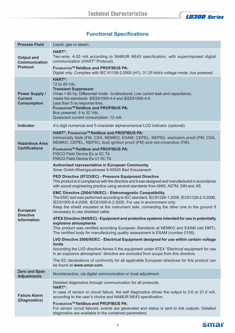
Process Fluid Liquid, gas or steam.
Output andCommunicationProtocol
HART®:Two-wire, 4-20 mA according to NAMUR NE43 specification, with superimposed digital communication (HART® Protocol).
FoundationTM fieldbus and PROFIBUS PA:Digital only. Complies with IEC 61158-2:2000 (H1): 31.25 kbit/s voltage mode, bus powered.
Power Supply /CurrentConsumption
HART®:12 to 45 Vdc.Transient SuppressorVmax = 65 Vp; Differential mode - bi-directional; Low current leak and capacitance;meets the standards: IEEE61000-4-4 and IEEE61000-4-5;Less than 5 ns response time.FoundationTM fieldbus and PROFIBUS PA:Bus powered: 9 to 32 Vdc.Quiescent current consumption: 12 mA.
Indicator 4½-digit numerical and 5-character alphanumerical LCD indicator (optional).
Hazardous AreaCertifications
HART®, FoundationTM fieldbus and PROFIBUS PA:Intrinsically Safe (FM, CSA, NEMKO, EXAM, CEPEL, NEPSI), explosion proof (FM, CSA, NEMKO, CEPEL, NEPSI), dust ignition proof (FM) and non-incendive (FM).
FoundationTM fieldbus and PROFIBUS PA:FISCO Field Device Ex ia IIC T4FNICO Field Device Ex n1 IIC T4
EuropeanDirectiveInformation
Authorized representative in European CommunitySmar Gmbh-Rheingaustrasse 9-55545 Bad Kreuzanach
PED Directive (97/23/EC) - Pressure Equipment DirectiveThis product is in compliance with the directive and it was designed and manufactured in accordance with sound engineering practice using several standards from ANSI, ASTM, DIN and JIS.
EMC Directive (2004/108/EC) - Eletromagnetic CompatibilityThe EMC test was performed according to IEC standard: IEC61326-1:2006, IEC61326-2-3:2006, IEC61000-6-4:2006, IEC61000-6-2:2005. For use in environment only.Keep the shield insulated at the instrument side, connecting the other one to the ground if necessary to use shielded cable.
ATEX Directive (94/9/EC) - Equipment and protective systems intended for use in potentially explosive atmospheresThis product was certified according European Standards at NEMKO and EXAM (old DMT). The certi fied body for manufacturing quality assessment is EXAM (number 0158).
LVD Directive 2006/95/EC - Electrical Equipment designed for use within certain voltage limitsAccording the LVD directive Annex II the equipment under ATEX “Electrical equipment for use in an explosive atmosphere” directive are excluded from scope from this directive. The EC declarations of conformity for all applicable European directives for this product can be found at www.smar.com.
Failure Alarm(Diagnostics)
Detailed diagnostics through communication for all protocols.HART®:In case of sensor or circuit failure, the self diagnostics drives the output to 3.6 or 21.0 mA, according to the user’s choice and NAMUR NE43 specification.
FoundationTM fieldbus and PROFIBUS PA:For sensor circuit failures, events are generated and status is sent to link outputs. Detailed diagnostics are available in the contained parameters.
Zero and SpanAdjustments Noninteractive, via digital communication or local adjustment.
8
Technical Characteristics
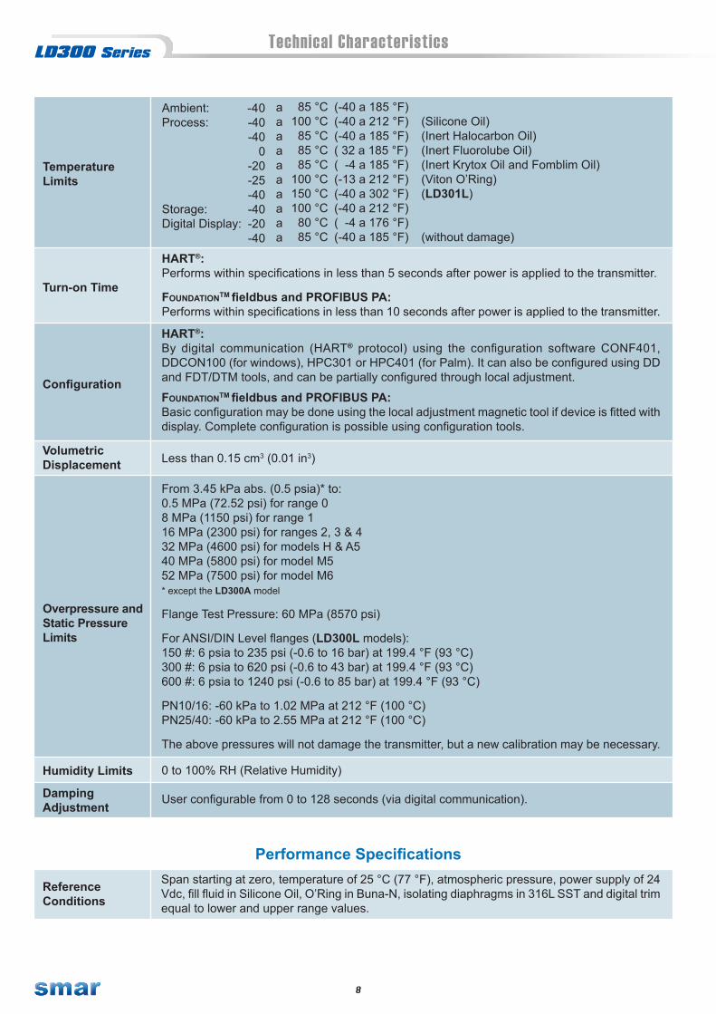
HART®:By digital communication (HART® protocol) using the configuration software CONF401, DDCON100 (for windows), HPC301 or HPC401 (for Palm). It can also be configured using DD and FDT/DTM tools, and can be partially configured through local adjustment.
FoundationTM fieldbus and PROFIBUS PA:Basic configuration may be done using the local adjustment magnetic tool if device is fitted with display. Complete configuration is possible using configuration tools.
VolumetricDisplacement Less than 0.15 cm3 (0.01 in3)
From 3.45 kPa abs. (0.5 psia)* to:0.5 MPa (72.52 psi) for range 08 MPa (1150 psi) for range 116 MPa (2300 psi) for ranges 2, 3 & 432 MPa (4600 psi) for models H & A540 MPa (5800 psi) for model M552 MPa (7500 psi) for model M6* except the LD300A model
Flange Test Pressure: 60 MPa (8570 psi)
For ANSI/DIN Level flanges (LD300L models):150 #: 6 psia to 235 psi (-0.6 to 16 bar) at 199.4 °F (93 °C)300 #: 6 psia to 620 psi (-0.6 to 43 bar) at 199.4 °F (93 °C)600 #: 6 psia to 1240 psi (-0.6 to 85 bar) at 199.4 °F (93 °C)
PN10/16: -60 kPa to 1.02 MPa at 212 °F (100 °C)PN25/40: -60 kPa to 2.55 MPa at 212 °F (100 °C)
The above pressures will not damage the transmitter, but a new calibration may be necessary.
Configuration
Humidity Limits 0 to 100% RH (Relative Humidity)
Overpressure andStatic PressureLimits
User configurable from 0 to 128 seconds (via digital communication).DampingAdjustment
TemperatureLimits
Ambient: Process:
Storage: Digital Display:
Turn-on Time
HART®:Performs within specifications in less than 5 seconds after power is applied to the transmitter.
FoundationTM fieldbus and PROFIBUS PA:Performs within specifications in less than 10 seconds after power is applied to the transmitter.
Performance Specifications
ReferenceConditions
Span starting at zero, temperature of 25 °C (77 °F), atmospheric pressure, power supply of 24 Vdc, fill fluid in Silicone Oil, O’Ring in Buna-N, isolating diaphragms in 316L SST and digital trim equal to lower and upper range values.
-40-40-40
0-20-25-40-40-20-40
85 °C100 °C85 °C85 °C85 °C
100 °C150 °C100 °C80 °C85 °C
aaaaaaaaaa
(-40 a 185 °F) (-40 a 212 °F) (Silicone Oil)(-40 a 185 °F) (Inert Halocarbon Oil)( 32 a 185 °F) (Inert Fluorolube Oil)( -4 a 185 °F) (Inert Krytox Oil and Fomblim Oil)(-13 a 212 °F) (Viton O’Ring)(-40 a 302 °F) (LD301L)(-40 a 212 °F)( -4 a 176 °F)(-40 a 185 °F) (without damage)

9
Technical Characteristics
Accuracy
Zero error:For ranges 2, 3, 4, 5 and 6: ± 0.033% URL per 7 MPa (1000 psi)For range 1: ± 0.05% URL per 1.7 MPa (250 psi)For range 0: ± 0.1% URL per 0.5 MPa (5 bar)For Level transmitters: ± 0.1% URL per 3.5 MPa (500 psi)The zero error is a systematic error that can be eliminated by calibrating at the operating static pressure.Span error:For ranges 2, 3, 4, 5 and 6: correctable to ± 0.2% of reading per 7 MPa (1000 psi)For range 1 and level transmitters: correctable to ± 0.2% of reading per 3.5 MPa (500 psi)For range 0: correctable to ± 0.2% of reading per 0.5 MPa (5 bar)
Power SupplyEffect ± 0.005% of calibrated span per volt.
Static PressureEffect
TemperatureEffect
For ranges 2, 3, 4, 5 and 6: ± 0.15% of URL for 5 years at 20 oC temperature change and up to 7 MPa (1000 psi) of static pressureFor ranges 0 and 1: ± 0.2% of URL for 12 months at 20 oC temperature change and up to 100 kPa (1 bar) of static pressureFor Level transmitters: ± 0.2% of URL for 12 months at 20 oC temperature change
Stability
Zero shift of up to 250 Pa (1 inH2O) which can be calibrated out.No span effect.
Mounting PositionEffectElectromagneticInterferenceEffect
Approved according to IEC61326-1:2006, IEC61326-2-3:2006, IEC61000-6-4:2006, IEC61000-6-2:2005.
For range 0, and differential or gage models and 316L SST or hastelloy diaphragm with silicon or halocarbon filling fluid:0.2 URL ≤ span ≤ URL: ± 0.1% of span0.05 URL ≤ span < 0.2 URL: ± [0.025+0.015 URL/span]% of span For ranges 1, 2, 3, 4, 5 or 6, differential or gage models, and 316L SST or hastelloy diaphragm with silicon or halocarbon filling fluid:0.1 URL ≤ span ≤ URL: ± 0.075% of span0.025 URL ≤ span < 0.1 URL: ± [0.0375+0.00375.URL/span]% of span0.0083 URL ≤ span < 0.025 URL: ± [0.0015+0.00465.URL/span]% of spanFor ranges 2 to 6 and absolute model. For tantalum or monel diaphragm. For fluorolube filling fluid:0.1 URL ≤ span ≤ URL: ± 0.1% of span0.025 URL ≤ span < 0.1 URL: ± 0.05[1+0.1 URL/span]% of span 0.0083 URL ≤ span < 0.025 URL: ± [0.01+0.006 URL/span]% of span For range 1 and absolute model:± 0.2% of spanFor ranges 2, 3 or 4 and level model and 316L SST diaphragm with silicon or halocarbon filling fluid with maximum pressure matching the flange pressure class:0.1 URL ≤ span ≤ URL: ± 0.075% of span0.025 URL ≤ span < 0.1 URL: ± [0.0375+0.00375.URL/span]% of span0.0083 URL ≤ span < 0.025 URL: ± [0.0015+0.00465.URL/span]% of spanLinearity effects, hysterese and repeatability are included.
For ranges 2, 3, 4, 5 and 6:0.2 URL ≤ span ≤ URL: ± [0.02% URL + 0.06% span] per 20 oC (68 ºF)0.0085 URL ≤ span < 0.2 URL: ± [0.023% URL + 0.045% span] per 20 oC (68 ºF)For range 1:0.2 URL ≤ span ≤ URL: ± [0.08% URL + 0.05% span] per 20 oC (68 ºF)0.025 URL ≤ span < 0.2 URL: ± [0.06% URL + 0.15% span] per 20 oC (68 ºF)For range 0:0.2 URL ≤ span ≤ URL: ± [0.15% URL + 0.05% span] per 20 oC (68 ºF)0.05 URL ≤ span < 0.2 URL: ± [0.1% URL + 0.3% span] per 20 oC (68 ºF)For LD300L:6 mmH2O per 20 oC for 4” and DN10017 mmH2O per 20 oC for 3” and DN80Consult for other flange dimensions and fill fluid.

10
Technical Characteristics
Electronic Housing:Injected aluminum with polyester painting, epoxy painting or 316 SST - CF8M (ASTM - A351) housing.Complies with NEMA 4X/6P, IP66 ou IP66W*, IP68 ou IP68W*.Note: *The IP66/68W sealing test (immersion) was performed at 1 bar for 24 hours. For any other situation, please consult Smar. IP66/68W tested for 200h to according NBR 8094 / ASTM B 117 standard.
Blank Flange:When flange adapter and Drain/Vent material is Carbon Steel, blank flange is in Carbon Steel, otherwise blank flange is in 316 SST CF8M (ASTM - A351).Level Flange (LD300L):316L SST, 304 SST, Hastelloy C276 and Plated Carbon Steel.Fill Fluid:Silicone, Fluorolube, Krytox, Halocarbon 4.2 or Fomblim oils.Cover O’Ring:Buna-NMounting Bracket:Plated Carbon Steel or 316 SST.Accessories (bolts, nuts, washers and U-clamps) in Carbon Steel or 316 SST.Flange Bolts and Nuts:Plated Carbon Steel, Grade 8 or 316 SST.For NACE applications: Carbon Steel ASTM A193 B7M.Identification Plate:316 SST.
Mounting
a) Flange mounted for Level models.b) Optional universal mounting bracket for surface or vertical/horizontal 2”-pipe (DN 50).c) Manifold Valve integrated to the transmitter.d) Directly on piping for closely coupled transmitter/orifice flange combinations.
Control FunctionsCharacteristics(Optional)
HART®
PID Control (PID) and Totalizer (TOT)
FoundationTM fieldbusResource (RS), Transducer (TRD), Diagnostics Transducer Block (DIAG), Analog Input (AI), PID Control (PID), Advanced PID Control (APID), Arithmetic (ARTH), Integrator (INTG), Input Selector(ISEL), Signal Characterizer (CHAR), Analog Alarm (AALM), Timer and Logic (TIME), Lead Lag (LLAG), Output Signal Selector and Dynamic Limiter (OSDL), Constant (CT) and Density (DENS).
PROFIBUS PAPhysical Block (PHY), Transducer (TRD), Analog Input (AI) and Totalizer (TOT)
ApproximateWeights
3.15 kg (7 lb): all models, except L models.5.85 to 9.0 kg (13 lb to 20 lb): L models depending on the flanges, extension and materials.
Nonwetted Parts
Physical Specifications
ProcessConnection
¼ - 18 NPT or ½ -14 NPT (with adapter).For L models see Ordering Code.See Ordering Code for more options.Isolating Diaphragms:316L SST, Hastelloy C276, Monel 400 or Tantalum.Drain/Vent Valves and Plug:316 SST, Hastelloy C276 or Monel 400.Flanges:Plated Carbon Steel, 316 SST CF8M (ASTM - A351), Hastelloy C276 - CW-12MW, (ASTM - A494) or Monel 400.Wetted O-Rings (For Flanges and Adapters):Buna-N, Viton™, PTFE or Ethylene-Propylene.The LD300 is available in NACE MR-01-75/ISO 15156 compliant materials.
Wetted Parts
½ - 14 NPT ¾ – 14 NPT (with 316 SST adapter for 1/2 - 14 NPT)M20 X 1.5 ¾ – 14 BSP (with 316 SST adapter for 1/2 - 14 NPT)PG 13.5 DIN ½ – 14 BSP (with 316 SST adapter for 1/2 - 14 NPT)
ElectricalConnection

11
Technical Characteristics of High Performance - CODE L1
Accuracy
Hastelloy is a trademark of the Cabot Corp.Monel is a trademark of International Nickel Co.Viton and Teflon are trademarks of E. I. DuPont de Nemours & Co.
For range 2:0.2 URL ≤ span ≤ URL: ± 0.04% of span0.05 URL ≤ span < 0.2 URL: ± [0.021667 + 0.003667 URL/span]% of span0.0085 URL ≤ span < 0.05 URL: ± [0.0021 + 0.004645 URL/span]% of span
For range 3 and 4:0.1 URL ≤ span ≤ URL: ± 0.05% of span0.05 URL ≤ span < 0.1 URL: ± [0.005 + 0.0045 URL/span]% of span0.0085 URL ≤ span < 0.05 URL: ± [0.0021 + 0.004645 URL/span]% of span
TemperatureEffect
From -10 oC to 50 oC, protected from direct sun radiation:0.2 URL ≤ span ≤ URL: ± [0.018% URL + 0.012% span] per 20 oC (36 oF)0.0085 URL ≤ span < 0.2 URL: ± [0.02% URL + 0.002% span] per 20 oC (36 oF)
Stability
For range 2: ± 0.05% of URL for 6 monthsFor range 3: ± 0.075% of URL for 12 monthsFor range 4: ± 0.1% of URL for 24 months± 0.2% of URL for 12 years, at 20 °C temperature change and up to 7 MPa (1000 psi) {70 bar} of static pressure, environment free of hydrogen migration.
Static PressureEffect
Zero error:± 0.025% URL per 7 MPa (1000 psi)The zero error is a systematic error that can be eliminated by calibrating at the operating static pressure.
Span error:Correctable to ± 0.2% of reading per 7 MPa (1000 psi).
Range
316L SSTHastelloy C276
Fill Fluid Silicone
Application DifferentialGage
DiaphragmMaterial
Performance Specifications (Code L1)
High Performance option (code L1) is available under the following conditions only:
D2: -50 to 50 kPa D3: -250 to 250 kPa D4: -2500 to 2500 kPaM2: -50 to 50 kPa M3: -100 to 250 kPa M4: -100 to 2500 kPa
ReferenceConditions
Span starting at zero, temperature of 25 °C (77 °F), atmospheric pressure, power supply of24 Vdc, silicone oil fill fluid, isolating diaphragms in 316L SST and digital trim equal to lower and upper range values.
-200 to 200 inH2O -36 to 36 psi -360 to 360 psi -200 to 200 inH2O -14.5 to 36 psi -14.5 to 360 psi
Fluorolube is a trademark of Hooker Chemical Corp.Halocarbon is a trademark of Halocarbon.HART® is a trademark of HART® Communication Foundation.
Foundation is a trademark of Fieldbus Foundation.Profibus is a trademark of Profibus International.Smar Pressure Transmitters are protected by US patent number 6,433,791
12
Ordering Code
Range Limits Min. Span
-4-20
-200-36
-360
-4-20
-200- 14.50- 14.50- 14.50- 14.50
000000
- 200- 36
- 360- 3600
420
20036
360
420
20036
36036005800
377.236
36036005800
20036
3603600
0.20.5
1.670.3
3
0.20.5
1.670.3
330
48.3
14.80.360.73
330
48.3
1.670.3
330
Min MaxUnit
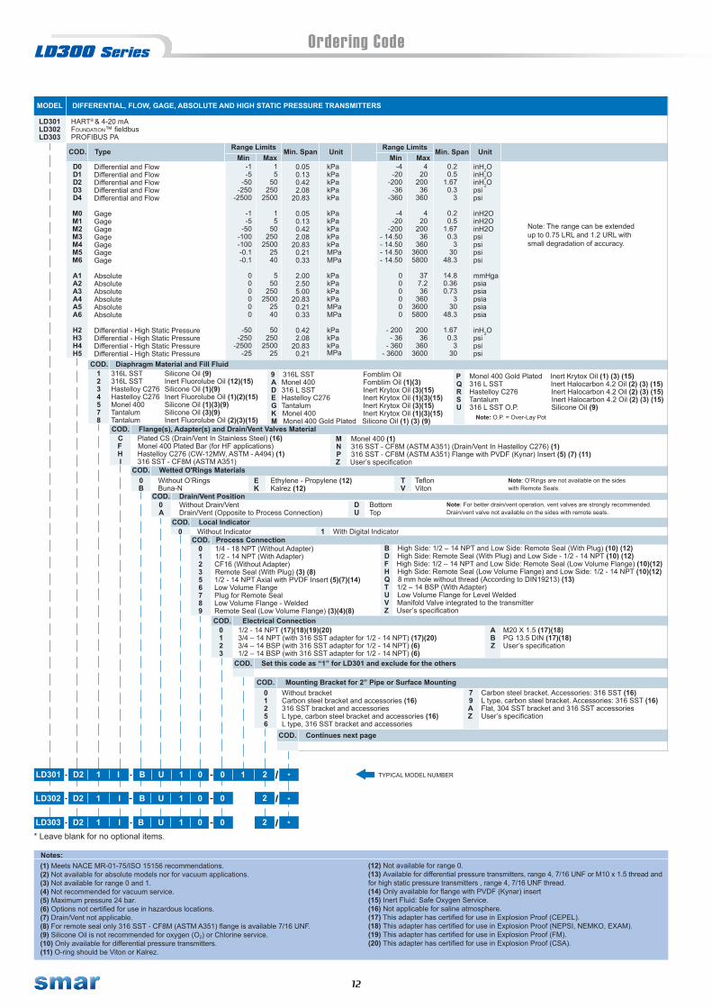
MODEL DIFFERENTIAL, FLOW, GAGE, ABSOLUTE AND HIGH STATIC PRESSURE TRANSMITTERS
COD. Type
COD. Diaphragm Material and Fill Fluid 1 316L SST Silicone Oil (9)2 316L SST Inert Fluorolube Oil (12)(15)3 Hastelloy C276 Silicone Oil (1)(9)4 Hastelloy C276 Inert Fluorolube Oil (1)(2)(15)5 Monel 400 Silicone Oil (1)(3)(9)7 Tantalum Silicone Oil (3)(9)8 Tantalum Inert Fluorolube Oil (2)(3)(15)
C Plated CS (Drain/Vent In Stainless Steel) (16) F Monel 400 Plated Bar (for HF applications) H Hastelloy C276 (CW-12MW, ASTM - A494) (1) I 316 SST - CF8M (ASTM A351)
COD. Flange(s), Adapter(s) and Drain/Vent Valves Material
0 Without O’Rings B Buna-N
COD. Wetted O'Rings Materials
0 Without Drain/VentA Drain/Vent (Opposite to Process Connection)
COD. Drain/Vent Position
0 Without Indicator COD. Local Indicator
0 1/4 - 18 NPT (Without Adapter) 1 1/2 - 14 NPT (With Adapter) 2 CF16 (Without Adapter) 3 Remote Seal (With Plug) (3) (8) 5 1/2 - 14 NPT Axial with PVDF Insert (5)(7)(14) 6 Low Volume Flange 7 Plug for Remote Seal 8 Low Volume Flange - Welded 9 Remote Seal (Low Volume Flange) (3)(4)(8)
COD. Process Connection
COD. Electrical Connection 0 1/2 - 14 NPT (17)(18)(19)(20) 1 3/4 – 14 NPT (with 316 SST adapter for 1/2 - 14 NPT) (17)(20) 2 3/4 – 14 BSP (with 316 SST adapter for 1/2 - 14 NPT) (6) 3 1/2 – 14 BSP (with 316 SST adapter for 1/2 - 14 NPT) (6)
COD. Set this code as “1” for LD301 and exclude for the others
COD. Mounting Bracket for 2” Pipe or Surface Mounting0 Without bracket1 Carbon steel bracket and accessories (16) 2 316 SST bracket and accessories 5 L type, carbon steel bracket and accessories (16)6 L type, 316 SST bracket and accessories
Note: For better drain/vent operation, vent valves are strongly recommended.Drain/vent valve not available on the sides with remote seals.
Differential and FlowDifferential and FlowDifferential and FlowDifferential and FlowDifferential and Flow
GageGageGageGageGageGageGage
Absolute Absolute Absolute Absolute AbsoluteAbsolute
Differential - High Static PressureDifferential - High Static PressureDifferential - High Static PressureDifferential - High Static Pressure
D0D1D2D3D4
M0M1M2M3M4M5M6
A1A2A3A4A5A6
H2H3H4H5
9 316L SST Fomblim Oil A Monel 400 Fomblim Oil (1)(3) D 316 L SST Inert Krytox Oil (3)(15) E Hastelloy C276 Inert Krytox Oil (1)(3)(15) G Tantalum Inert Krytox Oil (3)(15) K Monel 400 Inert Krytox Oil (1)(3)(15) M Monel 400 Gold Plated Silicone Oil (1) (3) (9)
Range Limits Min. Span
TYPICAL MODEL NUMBER
-1-5
-50-250
-2500
-1-5
-50-100-100-0.1-0.1
000000
-50-250
-2500-25
15
50250
2500
15
50250
25002540
550
2502500
2540
50250
250025
kPakPakPakPakPa
kPakPakPakPakPaMPaMPa
kPa kPakPakPa MPaMPa
kPakPakPaMPa
0.05 0.13 0.42 2.08
20.83
0.05 0.13 0.42 2.08
20.83 0.21 0.33
2.00 2.50 5.00
20.83 0.21 0.33
0.42 2.08
20.83 0.21
P Monel 400 Gold Plated Inert Krytox Oil (1) (3) (15) Q 316 L SST Inert Halocarbon 4.2 Oil (2) (3) (15) R Hastelloy C276 Inert Halocarbon 4.2 Oil (2) (3) (15) S Tantalum Inert Halocarbon 4.2 Oil (2) (3) (15) U 316 L SST O.P. Silicone Oil (9) Note: O.P. = Over-Lay Pot
M Monel 400 (1) N 316 SST - CF8M (ASTM A351) (Drain/Vent In Hastelloy C276) (1) P 316 SST - CF8M (ASTM A351) Flange with PVDF (Kynar) Insert (5) (7) (11) Z User’s specification
Note: O’Rings are not available on the sides with Remote Seals.
E Ethylene - Propylene (12) K Kalrez (12)
D BottomU Top
1 With Digital Indicator
B High Side: 1/2 – 14 NPT and Low Side: Remote Seal (With Plug) (10) (12)D High Side: Remote Seal (With Plug) and Low Side - 1/2 - 14 NPT (10) (12)F High Side: 1/2 – 14 NPT and Low Side: Remote Seal (Low Volume Flange) (10)(12)H High Side: Remote Seal (Low Volume Flange) and Low Side: 1/2 - 14 NPT (10)(12)Q 8 mm hole without thread (According to DIN19213) (13)T 1/2 – 14 BSP (With Adapter)U Low Volume Flange for Level WeldedV Manifold Valve integrated to the transmitterZ User’s specification
A M20 X 1.5 (17)(18) B PG 13.5 DIN (17)(18) Z User’s specification
7 Carbon steel bracket. Accessories: 316 SST (16) 9 L type, carbon steel bracket. Accessories: 316 SST (16) A Flat, 304 SST bracket and 316 SST accessories Z User’s specification
COD. Continues next page
*LD302 D2 1 I B U 1 0 0
LD303 D2 1 I B U 1 0 0 *
(1) Meets NACE MR-01-75/ISO 15156 recommendations.(2) Not available for absolute models nor for vacuum applications.(3) Not available for range 0 and 1.(4) Not recommended for vacuum service.(5) Maximum pressure 24 bar.(6) Options not certified for use in hazardous locations.(7) Drain/Vent not applicable.(8) For remote seal only 316 SST - CF8M (ASTM A351) flange is available 7/16 UNF. (9) Silicone Oil is not recommended for oxygen (O2) or Chlorine service.(10) Only available for differential pressure transmitters.(11) O-ring should be Viton or Kalrez.
Notes:(12) Not available for range 0.(13) Available for differential pressure transmitters, range 4, 7/16 UNF or M10 x 1.5 thread and for high static pressure transmitters , range 4, 7/16 UNF thread.(14) Only available for flange with PVDF (Kynar) insert(15) Inert Fluid: Safe Oxygen Service.(16) Not applicable for saline atmosphere.(17) This adapter has certified for use in Explosion Proof (CEPEL).(18) This adapter has certified for use in Explosion Proof (NEPSI, NEMKO, EXAM).(19) This adapter has certified for use in Explosion Proof (FM).(20) This adapter has certified for use in Explosion Proof (CSA).
Min MaxUnit
inH2OinH2OinH2Opsipsi
inH2OinH2OinH2Opsipsipsipsi
mmHgapsiapsiapsiapsiapsia
inH2Opsipsipsi
LD301 HART® & 4-20 mALD302 Foundation™ fieldbusLD303 PROFIBUS PA
Note: The range can be extended up to 0.75 LRL and 1.2 URL with small degradation of accuracy.
2
2
T Teflon V Viton
LD301 D2 1 I B U 1 0 0 *21
* Leave blank for no optional items.
13
Ordering Code (Continued)
G3
Without CertificationDekra/EXAM: Group I, M1 Ex-ia0 to 20 mA: LD301 (2)NEPSI: Ex-ia, Ex-dNEPSI: Ex-ia (5)
D2 M12 X 1.75
A2A5
Carbon Steel (ASTM A193 B7M) (1) (8)Hastelloy C276
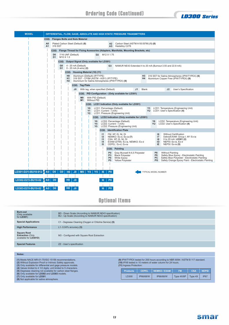
DIFFERENTIAL, FLOW, GAGE, ABSOLUTE AND HIGH STATIC PRESSURE TRANSMITTERS
A0A1
MODEL
COD.
LD301-D21I-BU10-012 A0 D0 H0 J0 M0 Y0 I6 P0G0
Flanges Bolts and Nuts Material
Plated Carbon Steel (Default) (8)316 SST
D0D1
COD. Flange Thread for Fixing Acessories (Adapters, Manifolds, Mounting Brackets, etc)
7/16 UNF (Default)M10 X 1.5
G0G1
COD. Output Signal (Only available for LD301)
4 - 20 mA (Default)0 - 20 mA (4-wire) (2)
H0H1H2
COD. Housing Material (10) (11)Aluminum (Default) (IP/TYPE)316 SST - CF8M (ASTM - A351) (IP/TYPE)Aluminium for Saline Atmospheres (IPW/TYPEX) (9)
J0COD. Tag Plate
With tag, when specified (Default)
M0M1
COD. PID Configuration - (Only available for LD301)
With PID (Default) Without PID
LD302-D21I-BU10-02
LD303-D21I-BU10-02
Optional ItemsBurn-out(Only availablefor LD301)
BD - Down Scale (According to NAMUR NE43 specification)BU - Up Scale (According to NAMUR NE43 specification)
Special Applications C1 - Degrease Cleaning (Oxygen or Chlorine Service) (5)
High Performance L1- 0.04% accuracy (3)
Y5
Y0Y1Y2
COD. LCD1 Indication (Only available for LD301)
LCD1: Percentage (Default)LCD1: Current - I (mA)LCD1: Pressure (Engineering Unit)
Y3YU
LCD1: Temperature (Engineering Unit)LCD1: User’s Specification (4)
Y0Y4Y5
COD. LCD2 Indication (Only available for LD301)
LCD2: Percentage (Default)LCD2: Current - I (mA)LCD2: Pressure (Engineering Unit)
Y6YU
LCD2: Temperature (Engineering Unit)LCD2: User’s Specification (4)
I1I2I3I4I5
COD. Identification Plate
FM: XP, IS, NI, DINEMKO: Ex-d, Ex-ia (7)CSA: XP, IS, NI, DIEXAM (DTM): Ex-ia, NEMKO: Ex-dCEPEL: Ex-d, Ex-ia
P0P3P4P5
COD. Painting
Gray Munsell N 6,5 PolyesterBlack PolyesterWhite EpoxyYellow Polyester
P8 Without Painting P9 Safety Blue Epoxy - Electrostatic Painting PC Safety Blue Polyester - Electrostatic Painting PG Safety Orange Epoxy Paint - Electrostatic Painting
TYPICAL MODEL NUMBER
Square RootExtraction (Onlyavailable for LD301D)
M3 - Configured with Square Root Extraction
A0 D0 J0 I6 P0
A0 D0 I6 P0
(1) Meets NACE MR-01-75/ISO 15156 recommendations.(2) Without Explosion Proof or Intrinsic Safety approvals.(3) Only available for differential and gage pressure models.(4) Values limited to 4 1/2 digits; unit limited to 5 characters.(5) Degrease cleaning not available for carbon steel flanges.(6) Only available for LD302 and LD303 models.(7) Only available for LD301.(8) Not applicable for saline atmosphere.
Notes:
(9) IPW/TYPEX tested for 200 hours according to NBR 8094 / ASTM B 117 standard.(10) IPX8 tested in 10 meters of water column for 24 hours.(11) Ingress Protection:
Special Features ZZ - User’s specification
J0
H0
H0
316 SST for Saline Atmospheres (IPW/TYPEX) (9)Aluminium Copper Free (IPW/TYPEX) (9)
H3H4
Products CEPEL NEMKO / EXAM FM CSA NEPSI
LD300 IP66/68/W IP66/68/W Type 4X/6P Type 4X IP67
NAMUR NE43 Extended 4 to 20 mA (Burnout 3.55 and 22.8 mA)
J1 Blank J2 User’s Specification
I6I7I8IDIE

14
Ordering Code
Stainless 316 LIGrafoil (Flexible lead) Copper
GC
Super Duplex (UNS 32750) (11)Duplex (UNS 31803) (11)Monel
34M
HGB
Halocarbon 4.2Glycerin + Water (11)Fomblim 06/06
DN 25 PN 10/40 (33)DN 40 PN 10/40DN 50 PN 10/40DN 80 PN 10/40DN 100 PN 10/16DN 100 PN 25/40JIS 40A 20K (21)JIS 50A 10K (21)
5RE678SF
2” 600 # (ANSI B16.53” 150 # (ANSI B16.5)3” 300 # (ANSI B16.5)3” 600 # (ANSI B16.5)3" 600 # (ANSI B16.5 RTJ)4” 150 # (ANSI B16.5)4” 300 # (ANSI B16.5)4” 600 # (ANSI B16.5)
B12CN34D
EK
Tantalum316L SSTMonel 400316L SSTHastelloy C276Tantalum
89ADEG
Inert Fluorolube Oil (3) (26)Fomblim OilFomblim Oil (1)Inert Krytox Oil (26)Inert Krytox Oil (1) (26) Inert Krytox Oil (26)
COD. Flange, Adapter and Drain/Vent Valves material (Low Side)
COD. Wetted O’Ring Material (Low Side)
COD. Process Connection (Low Side)
316L SST316L SSTHastelloy C276Hastelloy C276Monel 400Tantalum
123457
Silicone Oil (2)Inert Fluorolube Oil (3) (26)Silicone Oil (1) (2)Inert Fluorolube Oil (1) (3) (26)Silicone Oil (1) (2)Silicone Oil (2)
Monel 400 Monel 400 Gold PlatedMonel 400 Gold Plated316L SSTHastelloy C276Tantalum
KMPQRS
Inert Krytox Oil (1) (26)Silicone Oil (1) (2)Inert Krytox Oil (1) (26)Inert Halocarbon 4.2 Oil (26)Inert Halocarbon 4.2 Oil (1) (26)Inert Halocarbon 4.2 Oil (26)
IMNP
304L SSTPlated CS (Drain/Vent in Stainless Steel) (22)Monel 400 Plated Bar (for HF applications)Hastelloy C276 (CW – 12MW, ASTM – A494) (1)
ACFH
316 SST – CF8M (ASTM – A351)Monel 400 (1)316 SST – CF8M (ASTM – A351) (Drain/Vent in Hastelloy C276) (1)316 SST – CF8M (ASTM – A351) Flange with PVDF (Kynar) insert (3) (4) (5)
Without O’RingsBuna-N
0B
Ethylene - PropyleneKalrez
Note: O’rings are not available on the sides with remote seals.
DU
COD. Drain/Vent Position (Low Side)Without Drain/VentDrain/Vent (Opposite to Process Connection)
0A
LowUpper
Nota: For better Drain/Vent operation, vent valves are strongly recommended. Drain/Vent valve are not available on the sides with remote seals
1COD. Local Indicator
Without Indicator0 With Digital indicator
6789T
1/4 - 18 NPT (Without Adapter)1/2 - 14 NPT (Without Adapter)CF16 (Without Adapter)Remote Seal (With Plug ) (7)1/2 - 14 NPT Axial with PVDF Insert (3) (4) (6)
01235
Low Volume Flange - 1/4 NPTPlug for Remote SealLow Volume Flange - WeldedRemote Seal (Low Volume Flange) (3) (7)1/2 14 BSP (With Adapter)
COD. Electrical ConnectionABZ
1/2 – 14 NPT (24)(29)(30)(31)3/4 – 14 NPT (with 316 SST adapter for ½ - 14 NPT) (24)(31)3/4 – 14 BSP (with 316 SST adapter for ½ - 14 NPT) (9)1/2 – 14BSP (with 316 SST adapter for ½ - 14 NPT) (9)
0123
M20 x 1.5 (24)(29)PG 13.5 DIN (24)(29)User’s specification
COD. Zero and Span Adjust With Zero and Span Adjustment1COD. Process Connection
1” 150 # (ANSI B16.5) (33)1” 300 # (ANSI B16.5) (33)1” 600 # (ANSI B16.5) (33)1.1/2” 150 # (ANSI B16.5)1.1/2” 300 # (ANSI B16.5)1.1/2” 600 # (ANSI B16.5)2” 150 # (ANSI B16.5)2” 300 # (ANSI B16.5)
UVWOPQ9A
COD. Material and Flange Type (Level Tap)316L SST (Integral Flange)User’s specification
2Z
COD. Extension Length23
0 mm (0”)50 mm (2”)
01
100 mm (4”)150 mm (6”)
COD. Diaphragm Material / Extension (Level Tap)4567
304L SST / 304L SST316L SST / 316 SSTHastelloy C276 / 316 SSTMonel 400 / 316 SST
A123
Tantalum / 316 SST (10)Titanium / 316 SST (10)316L SST with Teflon Lining (for 2”and 3”)316L SST with Gold Lining
Nota: Extension Material 316L SST
COD. Fill Fluid (Level Tap)TN4
DC 200 Silicone Oil DC 704 Silicone OilMO – 10 Fluorolube Oil (8)
132
Syltherm 800 OilNeobee M20 Propylene Glycol OilKrytox Oil
COD. Lower Housing Material
Without Lower Housing (12)Stainless Steel 316Hastelloy C276
012
COD. Gaskte Material
Without gasket Teflon (PTFE)
0T
COD. Continues Next Page
TV
TeflonViton
JIS 50A 40K (21)JIS 50A 20K (21)JIS 80A 10K (21)JIS 80A 20K (21)JIS 100A 10K (21)JIS 100A 20K (21)User’s specification
TKGLHMZ
4Z
200 mm (8”)User’s specification
Hastelloy C276 (Integral Flange)304 SST (Slip-on Flange)
34
* Leave it blank when there are not optional items.
* TYPICAL MODEL NUMBER
MODEL FLANGED PRESSURE TRANSMITTER
COD.
-50 -250-2500
-25000
L2L3L4L5
LD301LD302LD303
HART®
FOUNDATIONTM fieldbus
PROFIBUS PARange LimitsMin. Máx.
Min. Span Unit. Range LimitsMin. Máx.
Min. Span Unit.
50 2502500
25000
1.25 2.0820.83
208.30
kPakPakPakPa
-200 -36 -360-3625
200 36 3603625
5 0.3 330.2
inH2Opsipsipsi
Note: The range can be extended up to 0.75 LRL and 1.2 URL with small degradation of accuracy. The upper range value must be limited to the flange rating.
COD. Diaphragm material and Fill Fluid (Low Side)
UV
W
Low Volume Flange for Level WeldedWithout Connection (Mounted with Gage Flange)Without Connection (Absolut Reference)
316 SST (Slip-on Flange)Carbon Steel (Slip-on Flange)
56
BCL
Tantalum with Teflon LiningHastelloy with Teflon Lining316L Stainless Steel withHalar Lining (20)
LD301 L2 1 I 0 1 1 2 2 1 1 1B U 1 0 T
LD302 L2 1 I 0 1 1 2 2 1 1 1B U 1 0
LD303 L2 1 I 0 1 1 2 2 1 1 1B U 1 0
*
*
T
T
Optional Items

15
Ordering Code (Continued)
Special Procedures
BD - Down Scale (Accordance to NAMUR NE43 specification) BU - Up Scale (Accordance to NAMUR NE43 specification)
Special Features
C1 - Degrease Cleaning (Oxygen or Chlorine Service) (15) C2 – For Vacuum Application
Burnout
ZZ – User’s Specification.
U0 - With Flush Connection of 1/4” NPT (If supplied with housing) U3 - With Two Connections of 1/2” NPT - 14 NPT at 180° (With Lid)U1 - With Two Flush Connections of 1/4” NPT at 180° U4 - Without gastek connectionU2 - With Two Flush Connections of 1/4” NPT at 90°
Gasket Connection
Diaphragm Thickness (16) N0 - Default (25) N1 - 0.1mm (11)
K0 – Without Kit K1 – With KitInsulator Kit
Optional Items
G3
I6 Without Certification I7 Dekra/EXAM: Group I, M1 Ex-ia I8 0 to 20 mA: LD301 (13) ID NEPSI: Ex-ia, Ex-d IE NEPSI: Ex-ia (5)
D2 M12 X 1.75
A2A5
Carbon Steel (ASTM A193 B7M) (1) (22)Hastelloy C276
FLANGED PRESSURE TRANSMITTER
A0A1
MODEL
COD.
LD301-L21I-BU10-01-122111-T A0 D0 H0 J0 M0 Y0 I6 P0G0
Flanges Bolts and Nuts Material
Plated Carbon Steel (Default) (22)316 SST
D0D1
COD. Flange Thread for Fixing Acessories (Adapters, Manifolds, Mounting Brackets, etc)
7/16 UNF (Default)M10 X 1.5
G0G1
COD. Output Signal (Only available for LD301)
4 - 20 mA (Default)0 - 20 mA (4-wire) (13)
H0H1H2
COD. Housing Material (27) (28)Aluminum (Default) (IP/TYPE)316 SST - CF8M (ASTM - A351) (IP/TYPE)Aluminium for Saline Atmospheres (IPW/TYPEX) (23)
J0COD. Tag Plate
With tag, when specified (Default)
M0M1
COD. PID Configuration - (Only available for LD301)
With PID (Default) Without PID
LD302-L21I-BU10-01-122111-T
LD303-L21I-BU10-01-122111-T
Y5
Y0Y1Y2
COD. LCD1 Indication (Only available for LD301)
LCD1: Percentage (Default)LCD1: Current - I (mA)LCD1: Pressure (Engineering Unit)
Y3YU
LCD1: Temperature (Engineering Unit)LCD1: User’s Specification (14)
Y0Y4Y5
COD. LCD2 Indication (Only available for LD301)
LCD2: Percentage (Default)LCD2: Current - I (mA)LCD2: Pressure (Engineering Unit)
Y6YU
LCD2: Temperature (Engineering Unit)LCD2: User’s Specification (14)
I1I2I3I4I5
COD. Identification Plate
FM: XP, IS, NI, DINEMKO: Ex-d, Ex-ia (32)CSA: XP, IS, NI, DIEXAM (DTM): Ex-ia, NEMKO: Ex-dCEPEL: Ex-d, Ex-ia
P0P3P4P5P8P9PCPG
COD. Painting
Gray Munsell N 6,5 PolyesterBlack PolyesterWhite EpoxyYellow PolyesterWithout PaintingSafety Blue Epoxy - Electrostatic PaintingSafety Blue Polyester - Electrostatic PaintingSafety Orange Epoxy Paint - Electrostatic Painting
TYPICAL MODEL NUMBER
A0 D0 J0 I6 P0
A0 D0 I6 P0J0
H0
H0
316 SST for Saline Atmospheres (IPW/TYPEX) (23)Aluminium Copper Free (IPW/TYPEX) (23)
H3H4
NAMUR NE43 Extended 4 to 20 mA (Burnout 3.55 and 22.8 mA)
J1 Blank J2 User’s Specification
Q3Q4
Tongue Face (11)Grooved Face (11)
Q0Q1Q2
COD. Flange Facing Finish (18)
Raised Face - RF (Default)Flat Face - FFRing Joint Face - RTJ (Only available for ANSI standard flange) (17)
Q0
Q0
Q0
16
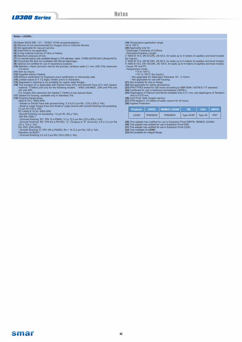
Notes
(1) Meets NACE MR – 01 – 75/ISO 15156 recommendations.(2) Silicone oil not recommended for Oxygen (O2) or Chlorine Service.(3) Not applicable for vacuum service.(4) Drain/Vent is not applicable.(5) O-ring material must be of Viton or Kalrez.(6) Maximum pressure 24 bar.(7) For remote seal is only available flange in 316 stainless steel– CF8M (ASTM A351) (thread M12).(8) Fluorolube fills fluid not available with Monel diaphragm.(9) Options not certified for use in hazardous locations.(10) Attention, check corrosion rate for the process, tantalum plate 0.1 mm, AISI 316L extension 3 to 6mm.(11) Item by inquiry.(12) Supplied without Gasket.(13) Without certification for Explosion proof certification or Intrinsically safe.(14) Limited values to 4 1/2 digits; limited unit to 5 characters.(15) Degreaser’s cleaning is not available for carbon steel flanges .(16) The insulator kit is applicable with Raised Face (HO) and Smooth Face (H1) with Gasket material. T(Teflon) and only for the following models: - ANSI until #600 , DIN until P40 and
JIS until 40K; - For models with extension the Gasket T (Teflon) it has special share.(17) Gasket for housing, available only in Stainless 316.(18) Finishing flange faces:
ANSI B 16.5 / MSS-SP6:- Raised or Smoth Face with gooved lining: 3.2 to 6.3 µm Ra (125 a 250 µ” AA);- Small or Large Tongue Face and Small or Large Groove with smooth finishing not exceeding:3.2 µm Rt (125 µ” AA);RTJ ANSI B 16.20 / MSS-SP6: -Smooth finishing not exceeding: 1.6 µm Rt (63 µ” AA); DIN EN-1092-1:- Grooved finishing “B1” (PN 10 a PN40): 3.2 a 12.5 µm Ra (125 a 500 µ” AA);- Smooth finishing “B2” (PN 63 a PN100), “C” (Tongue) e “D” (Groove): 0.8 a 3.2 µm Ra(32 a 125 µ” AA).Din 2501 (DIN 2526):- Smooth finishing “E” (PN 160 a PN250): Rz = 16 (3.2 µm Ra (125 µ” AA).Standard Jis B2201- Grooved finishing 3.2 a 6.3 µm Ra (125 a 250 µ” AA).
(19) Temperature application range:-40 to 150°C.(20) Applicable only for:- Diaphragm Thickness of 0.05mm.- Diameters/Capillary Length:2” ANSI B 16.5, DN 50 DIN, JIS 50 A, for seals up to 3 meters of capillary and level models(by inquiry).3” ANSI B 16.5, DN 80 DIN, JIS 80 A, for seals up to 5 meters of capillary and level models.4” ANSI B 16.5, DN 100 DIN, JIS 100 A, for seals up to 8 meters of capillary and level models.- Faces: RF and FF.- Temperature Limits: +10 to 100°C; +101 to 150°C (by inquiry). - Not applicable for diaphragm thickness: N1 - 0.10mm. - Not applicable for use with housing.(21) Not available for slip-on flange.(22) Not applicable for saline atmosphere.(23) IPW/TYPEX tested for 200 hours according to NBR 8094 / ASTM B 117 standard.(24) Certificate for use in explosive atmosphere (CEPEL).(25) Diaphragms of Titanium and Monel available only in 0.1 mm, and diaphragms of Tantalum only in 0.075 mm.(26) Inert Fluid: Safe Oxygen service.(27) IPX8 tested in 10 meters of water column for 24 hours.(28) Ingress Protection:
(29) This adapter has certified for use in Explosion Proof (NEPSI, NEMKO, EXAM).(30) This adapter has certified for use in Explosion Proof (FM).(31) This adapter has certified for use in Explosion Proof (CSA).(32) Only available for LD301.(33) Not available for integral flange.
Notes - LD300L:
Products CEPEL NEMKO / EXAM FM CSA NEPSI
LD300 IP66/68/W IP66/68/W Type 4X/6P Type 4X IP67

17
Ordering Code
Viton (11)V Buna-N (11)B
316L SSTI
Teflon (11)T
Threaded SMS 2" - without ext. / 316L SST (10) (11)Threaded SMS 3" - with ext. / 316L SST (10) (11)Threaded SMS 3" - without ext. / 316L SST (10) (11)Tri-Clamp 1 1/2" - without ext. / 316L SST (11)Tri-Clamp 1 1/2" HP - without ext. / 316L SST (8) (11)Tri-Clamp 2" - with ext. / 316L SST (11)Tri-Clamp 2" - without ext. / 316L SST (11)Tri-Clamp 2" HP - with ext. / 316L SST (8) (11)Tri-Clamp 2" HP - without ext. / 316L SST (8) (11)Tri-Clamp 3" - with ext. / 316L SST (11)Tri-Clamp 3" - without ext. / 316L SST (11)Tri-Clamp 3" HP - with ext. / 316L SST (8) (11)Tri-Clamp 3" HP - without ext. / 316L SST (8) (11)User's specification
EM1FQ6DNPIGJRZ
ET
Tantalum316L SSTMonel 400316L SSTHastelloy C276Tantalum
89ADEG
Inert Fluorolube Oil (3) (19)Fomblim OilFomblim Oil (1)Inert Krytox Oil (19)Inert Krytox Oil (1) (19)Inert Krytox Oil (19)
COD. Flange(s), Adapter (s) and Drain Valve(s) Material (Low Side)
COD. Wetted O-Ring Material (Low Side)
COD. Process Connection (Low Side)
316L SST316L SSTHastelloy C276Hastelloy C276Monel 400Tantalum
123457
Silicone Oil (2)Inert Fluorolube Oil (3) (19)Silicone Oil (1) (2)Inert Fluorolube Oil (1) (3) (19)Silicone Oil (1) (2)Silicone Oil (2)
Monel 400Monel 400 Gold PlatedMonel 400 Gold Plated316L SSTHastelloy C276Tantalum
KMPQRS
Inert Krytox Oil (1) (19)Silicone Oil (1) (2)Inert Krytox Oil (1) (19)Inert Halocarbon 4.2 Oil (19)Inert Halocarbon 4.2 Oil (1) (19)Inert Halocarbon 4.2 Oil (19)
Without O-RingBuna-N
0B
Ethylene - PropyleneTeflon (Approved 3A) (21)
Note: O-Rings are not available on the sides with remote seal.
DU
COD. Drain Position (Low Side)Without DrainDrain (Opposite to process connection)
0A
BottomTop
Note: For better drain operation, drain valves are strongly recommended. Drain valve are not available on the sides with remote seal
1COD. Local Indicator
Without Indicator0 With Digital Indicator
COD. Electrical ConnectionABZ
1/2 - 14 NPT (20)(23)(24)(25)3/4 - 14 NPT (With 316 SST adapter for 1/2 - 14 NPT) (20)(25)3/4 - 14 BSP (With 316 SST adapter for 1/2 - 14 NPT) (9)1/2 - 14 BSP (With 316 SST adapter for 1/2 - 14 NPT) (9)
0123
M20 X 1.5 (20)(23)PG 13.5 DIN (20)(23)User’s Specification
COD. Zero and Span Adjust With Local Adjustment1COD. Process Connection
Threaded DN25 DIN 11851 - with ext. / 316L SST (10) (11)Threaded DN40 DIN 11851 - with ext. / 316L SST (10) (11)Threaded DN40 DIN 11851 - without ext. / 316L SST (10)Threaded DN50 DIN 11851 - with ext. / 316L SST (10) (11)Threaded DN50 DIN 11851 - without ext. / 316L SST (10)Threaded DN80 DIN 11851 - with ext. / 316L SST (10) (11)Threaded DN80 DIN 11851 - without ext. / 316L SST (10)Threaded IDF 2" - with ext. / 316L SST (10) (11)Threaded IDF 2" - without ext. / 316L SST (10) (11)Threaded IDF 3" - with ext. / 316L SST (10) (11)Threaded IDF 3" - without ext. / 316L SST (10) (11)Threaded RJT 2" - with ext. / 316L SST (10) (11)Threaded RJT 2" - without ext. / 316L SST (10)Threaded RJT 3" - with ext. / 316L SST (10) (11)Threaded RJT 3" - without ext. / 316L SST (10)Threaded SMS 1 1/2" - without ext. / 316L SST (10) (11)Threaded SMS 2" - with ext. / 316L SST (10) (11)
89HVUXW4BK35CL2S7
COD. Diaphragm Material (High Side)Hastelloy C276H
TNK
DC 200 – Silicone OilDC 704 – Silicone OilFluorolube MO-10
Syltherm 800Neobee M20 (11)Krytox 1506
COD. Continues next page
VK
VitonKalrez
MODEL PRESSURE SANITARY TRANSMITTER
COD.
-50 -250-2500
-25000
S2S3S4S5
LD301LD302LD303
HART®
FOUNDATIONTM fieldbusPROFIBUS PA
Range LimitsMin. Máx. Min. Span Unit. Range Limits
Min. Máx. Min. Span Unit.
50 2502500
25000
1.252.08
20.83208.30
kPakPakPakPa
-200 -36 -360-3625
200 36 3603625
5 0.3 330.2
inH2Opsipsipsi
Nota: The range can be extended up to 0.75 LRL and 1.2 URL with small degradation of accuracy. The upper range value must be limited to the connection.
COD. Diaphragm Material and Fill Fluid ( Low Side)
COD. Wet O-ring Without O-ring0
* Leave it blank when there are not optional items.
LD301 S2 1 I 0 1 A I S TB U 1 0 TYPICAL MODEL NUMBER
COD. Tank Adapter
Without Tank AdapterWith Tank Adapter in 316 SST
01
COD. Tri-Clamp
02
COD. Fill FluidSDF
1 2
Without Tri-ClampWith Tri-Clamp in 304 SST
*
6789T
1/4 - 18 NPT (Without Adapter)1/2 - 14 NPT (Without Adapter)CF16 (Without Adapter)Remote Seal (With Plug ) (7)1/2 - 14 NPT Axial with PVDF Insert (3) (4) (6)
01235
Low Volume Flange - 1/4 NPTPlug for Remote SealLow Volume Flange - WeldedRemote Seal (Low Volume Flange) (3) (7)1/2 14 BSP (With Adapter)
UV
W
Low Volume Flange for Level WeldedWithout Connection (Mounted with GageFlange)Without Connection (Absolut Reference)
MNP
Plated CS (Drain/Vent in Stainless Steel) (18)Hastelloy C276 (CW – 12MW, ASTM – A494) (1)316 SST – CF8M (ASTM – A351)
CHI
Monel 400 (1)316 SST – CF8M (ASTM – A351) (Drain/Vent in Hastelloy C276) (1)316 SST – CF8M (ASTM – A351) Flange with PVDF (Kynar) insert (3) (4) (5)
HGB
Halocarbon 4.2Glycerin + Water (12)Fomblim 06/06
LD302 S2 1 I 0 1 A I S TB U 1 0 1 2 *
LD303 S2 1 I 0 1 A I S TB U 1 0 1 2 *
Note: ext. = extension HP = High Pressure

Ordering Code (Continued)
18
Note - LD300S:
Burn-out BD – Down Scale (Accordance to NAMUR NE43 specification)BU – Up Scale (Accordance to NAMUR NE43 specification)
Special ProceduresC1 – Degrease Cleaning (Oxygen or Chlorine Service) (15)C2 – For Vacuum Application C4 – Polishing of the wet parts according to 3A Certification (11) (12)
Special Features ZZ – User’s Specification
(1) Meets NACE MR-01-75/ISO 15156 recommendations.(2) Silicone oil not recommended for Oxygen (O2) or Chlorine Service.(3) Not applicable for vacuum service.(4) Drain not applicable.(5) O-Ring material must be of Viton or Kalrez.(6) Maximum pressure 24 bar.(7) For remote seal is only available flange in 316 Stainless Steel - CF8M (ASTM A351) (thread M12).(8) HP – High Pressure.(9) Options not certified for use in hazardous locations.(10) Not available for Tri-clamp.(11) Compliant with 3A-7403 standard for food and other applications where sanitary connections are required:
- Neobee M2O Fill Fluid- Finishing wet Face: 0,8 µm Ra (32 µ” AA)- Wet O-Ring: Viton, Buna-N and Teflon
(12) Item by inquiry.(13) Without certification for explosion proof or intrinsically safe.(14) Limited values to 4 1/2 digits; limited unit to 5 characters.
(15) Degrease cleaning is not available for Carbon Steel Flanges.(16) Temperature application range: -40 to 140 °C and Tables 5 and 6 from the following page.(17) Inert Fluid: Safe Oxygen service.(18) Not applicable for saline atmosphere.(19) IPW/TYPEX tested for 200 hours according to NBR 8094 / ASTM B 117 standard.(20) Certificate for use in Explosion Proof (CEPEL).(21) IPX8 tested in 10 meters of water column for 24 hours.(22) Ingress Protection:
(23) This adapter has certified for use in Explosion Proof (NEPSI, NEMKO, EXAM).(24) This adapter has certified for use in Explosion Proof (FM).(25) This adapter has certified for use in Explosion Proof (CSA).(26) Only available for LD301.
Optional Itens
Diaphragm Thickness N0 – DefaultN1 – 0.1mm (12)
Products CEPEL NEMKO / EXAM FM CSA NEPSI
LD300 IP66/68/W IP66/68/W Type 4X/6P Type 4X IP67
G3
I6 Without Certification I7 Dekra/EXAM: Group I, M1 Ex-ia I8 0 to 20 mA: LD301 (13) ID NEPSI: Ex-ia, Ex-d IE NEPSI: Ex-ia (5)
D2 M12 X 1.75
A2A5
Carbon Steel (ASTM A193 B7M) (1) (18)Hastelloy C276
PRESSURE SANITARY TRANSMITTER
A0A1
MODEL
COD.
LD301-S21I-BU10-01-AIST12 A0 D0 H0 J0 M0 Y0 I6 P0G0
Flanges Bolts and Nuts Material
Plated Carbon Steel (Default) (18)316 SST
D0D1
COD. Flange Thread for Fixing Acessories (Adapters, Manifolds, Mounting Brackets, etc)
7/16 UNF (Default)M10 X 1.5
G0G1
COD. Output Signal (Only available for LD301)
4 - 20 mA (Default)0 - 20 mA (4-wire) (13)
H0H1H2
COD. Housing Material (21) (22)Aluminum (Default) (IP/TYPE)316 SST - CF8M (ASTM - A351) (IP/TYPE)Aluminium for Saline Atmospheres (IPW/TYPEX) (19)
J0COD. Tag Plate
With tag, when specified (Default)
M0M1
COD. PID Configuration - (Only available for LD301)
With PID (Default) Without PID
LD302-S21I-BU10-01-AIST12
LD303-S21I-BU10-01-AIST12
Y5
Y0Y1Y2
COD. LCD1 Indication (Only available for LD301)
LCD1: Percentage (Default)LCD1: Current - I (mA)LCD1: Pressure (Engineering Unit)
Y3YU
LCD1: Temperature (Engineering Unit)LCD1: User’s Specification (14)
Y0Y4Y5
COD. LCD2 Indication (Only available for LD301)
LCD2: Percentage (Default)LCD2: Current - I (mA)LCD2: Pressure (Engineering Unit)
Y6YU
LCD2: Temperature (Engineering Unit)LCD2: User’s Specification (14)
I1I2I3I4I5
COD. Identification Plate
FM: XP, IS, NI, DINEMKO: Ex-d, Ex-ia (26)CSA: XP, IS, NI, DIEXAM (DTM): Ex-ia, NEMKO: Ex-dCEPEL: Ex-d, Ex-ia
P0P3P4P5
COD. Painting
Gray Munsell N 6,5 PolyesterBlack PolyesterWhite EpoxyYellow Polyester
P8 Without Painting P9 Safety Blue Epoxy - Electrostatic Painting PC Safety Blue Polyester - Electrostatic Painting PG Safety Orange Epoxy Paint - Electrostatic Painting
TYPICAL MODEL NUMBER
A0 D0 J0 I6 P0
A0 D0 I6 P0J0
H0
H0
316 SST for Saline Atmospheres (IPW/TYPEX) (19)Aluminium Copper Free (IPW/TYPEX) (19)
H3H4
NAMUR NE43 Extended 4 to 20 mA (Burnout 3.55 and 22.8 mA)
J1 Blank J2 User’s Specification

Dimensions
19
LD300 - Differential, Flow, Gage, Absolute and High Static PressureTransmitters with Mounting Bracket
TABLE 1
TABLE 1
(1.6
2)
41
,3
(2.85)
(3.94)
ADAPTER
(2.30)
(2.20)
5
4
58,3
56,0 71,5
73,8 (2.90)
(2.81)
(2.13)
RANGE
0-1-2-3
TABLE 1
54,0
Y
69,5
Z
(2.73)
Allow 150 mm minimum for localzero and span adjustment withmagnetic tool
Ø83
(Ø3
.27)
TERMINALCONNECTION
113
(4.45)
MOUNTING BRACKET
PLUG
LOCK
83
(3.27)
ELECTRICALCONNECTION
(7.04)
(3.5
4)
90
179
DN50
TUBE 2"
(2.31)6 58,7 74,2 (2.92)
72,5
100
96
,6
18
1,5
185
(7.1
5)
(3.8
)
(7.2
8)
48,7
(1.90)
Y
Z DIMENSIONS
OPTIONAL THREAD
(WITH ADAPTERS)
DRAIN / VENT
(WITHOUT ADAPTERS)
1/4 - 18 NPT

20
Dimensions
Flanged Pressure Transmitter with Integral Flange
O’RING
C1 C2
ØF
1
RTJ FACEFF FACE
83
100
72,5
18
1
(3.94)
(2.85)
(3.2
7)
(7.1
3)
94,2 C EXTENSION
ØG
ØE
ØA
ØB
ØF
D
LOCK
(3.27)
83
1/2 NPT
(4.45)
113
32,8
+1-0
(1.29) (3.72)
14
0
(5.5
1)
EN 1092-1 DIMENSIONS
JIS B 2202 DIMENSIONS

21
Dimensions
Flanged Pressure Transmitter with Integral Flange LD300L - Flanged Pressure Transmitter with Slip-on Flange
1/2 NPT
LOCK
ØG
C
154.8 max.
(6.1)
E
ØF
ØB
ØA
97
(3.8
0)
83
(3.27)
83
100
72.5
113
18
1
(3.94)
(2.85)
(4.45)
(3.2
7)
(7.1
3)
7.2
(0.28)
98
(3.8
5)
C
ØB
ØA
E
ØF
1
E
12
RF FACE
FF FACE RTJ FACE
ØD
ØF
2
ØB
ØA
C
49 max.
(1.93)
168.1209.5
190.5
215.9600
4" 300
600
150
273
228.6
254 200
120.7
152.4
168.1
CLASS
3"
150
300
600
2"
150
300
165.1
190.5
209.5
A
152.4
165.1
ANSI-B 16.5 DIMENSIONS
127
127
B
(6)
(6.5)
(7.5)
(8.25)
(9)
(10)
(10.75)
(6.5)
(8.25)
(4.75)
(5)
(6)
(6.62)
(7.5)
(7.87)
(8.5)
(5)
(6.62)
DN
158
158
158
127
127
127
92
92
92
(3.62)
(5)
(6.22)
(3.62)
(3.62)
(5)
(5)
(6.22)
(6.22)158
158
158
127
127
127
92
92
92
(5)
(6.22)
(3.62)
(3.62)
(5)
(5)
(6.22)
(6.22)
(3.62)
F (RF) F1 (FF) F2 (RTJ)
174.6
174.6
171.5
146.1
133.4
146.1
107.9
101.6
107.9
(4.00)
(5.25)
(6.75)
(4.25)
(4.25)
(5.75)
(5.75)
(6.87)
(6.87)
19
19
22
19
22
22
19
25
19
31.8
38.1
30.2
22.3
22.3
27
25.4
17.5
20.7
C E
(0.75)
(0.87)
(1)
(0.87)
(0.75)
(0.75)
(0.75)
(0.87)
(0.75)
(0.69)
(0.8)
(1)
(0.87)
(1.06)
(1.25)
(0.87)
(1.18)
(1.5)
73
8
8
8
8
# HOLES
73
73
48
48
48
G
4
8
8
4
8
(1.89)
(1.89)
(1.89)
(2.87)
(2.87)
(2.87)
89
89
89 (3.5)
(3.5)
(3.5)
D
123.8
149.2
149.2
149.2
114.3
123.8
82.6
82.6
82.6
(3.25)
(3.25)
(3.25)
(4.50)
(4.87)
(4.87)
(5.87)
(5.87)
(5.87)
1 1/2"
1"
150
300/600
150
300/600
79.4
114.3
127
156
108
124
98.4
88.9
(4.25)
(4.88)
(6.14)
(5)
(3.16)
(3.5)
(4.5)
(3.87)
73
73
50.8
50.8
(2)
(2.87)
(2)
(2.87)
73
73
50.8
50.8
(2.87)
(2)
(2.87)
(2)
19
16
22
16
22.2
17.5
14.3
17.5
(0.63)
(0.75)
(0.87)
(0.63)
(0.56)
(0.69)
(0.69)
(0.87) 40
40
4
4
4
4
(1.57)
(1.57)
-
-
-
-
-
-
-
-
-
-
18160
100
10/40 200 24
PN
80
50
A
EN 1092-1 / DIN2501 DIMENSIONS - RF/ FF
B C
138 8
E F G
(7.87) (0.71) (5.43)(0.95)(6.30)
DN
73 (2.87)
1812510/40 165 20 102 48 4(6.50) (1.89)(0.71) (4.01)(0.78)(4.92)
1818010/16 220 20 158 8(8.67) (0.71) (6.22)(0.78)(7.08) 89 (3.5)
2219025/40 235 24 162 8(9.25) (0.87) (6.38)(0.95)(7.50) 89 (3.5)
# HOLES
40
25
1811010/40 150 18 88 4(5.91) (0.71) (3.46)(0.71)(4.33) 73 (2.87)
148510/40 115 18 68 4(4.53) (0.55) (2.68)(0.71)(3.35) -
Allow 150 mm for local zero andspan adjustment with magnetic tool
ELECTRICCONNECTION
LEVEL DIAPHRAGM WITHOUT EXTENSION TERMINALCONNECTIONS
Plug
LEVEL DIAPHRAGM WITH EXTENSION
Extension
(Without Adapter)
Drain/Vent Valve
(With Adapter)
Adapter
1/4-18 NPT
1/2-14 NPT
-FOR 1” AND DN25 THE EXTENSION LENGTH IS 0 mm

22
Dimensions
LD300L - Flanged Pressure Transmitter with Housing
Drain/Vent
SealingGasket
Housing
RF / FF FACE
ØJ
ØH
O´Ring
RTJ FACE
2540
ØJ
ØF
1
ØH
1
100
80
DN
50
PN
4"
CLASS
3"
2"
DN
ALL
50A40K
10K
105 (4,13)
96 (3,78)
CLASS H J
80A20K
10K
132 (5,20)
126 (4,96)
100A 10K 151 (5,94)
1.1/2"
40
20K 81 (3,19)40A
ALL
48 (1,89)
60 (1,36)
60 (1,36)
89 (3,50)
89 (3,50)
115 (4,53)
H J
H J48 (1,89)
48 (1,89)
60 (2,36)
60 (2,36)
89 (3,50)
89 (3,50)
115 (4,53)
115 (4,53)
DN
158 (6,22)
138 (5,43)
102 (4,02)
158 (6,22)
127 (5,00)
91,9 (3,62)
73,2 (2,88)
88 (3,46)6002"
300
600
150
1.1/2"
150
300
ANSI-B 16.5 DIMENSIONS - RTJ FACE
108 (4,25)
108 (4,25)
102 (4,00)
90,5 (3,56)
82,5 (3,25)
90,5 (3,56)
H1 J
4"
3"
600
300
600
150
300
175 (6,88)
175 (6,88)
146 (5,75)
171 (6,75)
146 (5,75)
150 133 (5,25)
R19
R23
R22
R20
R20
R36
R31
R31
R29
R23
R37
R37
2500
1500114 (4,50)
92 (3,62)
R23
R20
2500
1500133 (5,25)
124 (4,88)R24
R26
82,6 (3,25)
68,3 (2,69)
65,1 (2,56)
68,3 (2,69)
F1
149,2 (5,87)
149,2 (5,87)
123,8 (4,87)
149,2 (5,87)
123,8 (4,87)
114,3 (4,50)
82,6 (3,25)
68,3 (2,69)
101,6 (4,00)
95,3 (3,75)
82,6 (3,25)
82,6 (3,25)
115 (4,53)
115 (4,53)
115 (4,53)
89 (3,50)
89 (3,50)
89 (3,50)
60 (2,36)
60 (2,36)
60 (2,36)
60 (2,36)
60 (2,36)
48 (1,89)
48 (1,89)
48 (1,89)
48 (1,89)
48 (1,89)
DN
DIMENSIONS IN mm (")
LOCK
Housing
Drain/Vent
DIMENSIONS IN mm (")
ANSI-B 16.5 DIMENSIONS
FORM D DIMENSIONS
DIMENSIONS
CLASS O`RING

23
Dimensions
LD300S - Sanitary Transmitter with Extension
CONDUITCONNECTION
91,2
LOCK
32,8
+1-0
67,6+2-0
Allow 150 mm minimum for localzero and span adjustment withmagnetic tool
ØD
ØG
ØD
ØC
ext.
ØG
ØD
ØC
ext.
E
ØC
ØD
ØG
ext.
ØF
E
ØC
ØD
ØG
ext.
E
ØC
ØG
ØD
ext.
E
DIN 11851SMS
RTJ
IDF
E
High Pressure - HPE
TRICLAMP
TANKADAPTERO’RING
TRICLAMP
A
A
AA
AØ
F
ØF
ØF
ØF
O’RINGTANK
ADAPTER
TRICLAMP
O’RINGTANK
ADAPTER
TANKADAPTER
TANKADAPTER
O’RINGO’RING
Dimensions in mm (”)CONNECTION WITHEXTENSION A ØC ØD E ØF ØG EXT.
LD300S
Tri-Clamp DN50 63.5 (2.5) 76.5 (3.01) 18 (0.71) 50.5 (1.99) 80 (3.15) 48 (1.89)8 (0.315)
Tri-Clamp DN50 HP 63.5 (2.5) 81 (3.19) 25 (0.98) 80 (3.15)8 (0.315)
Tri-Clamp - 2" 63.5 (2.5)8 (0.315) 76.5 (3.01) 18 (0.71) 80 (3.15)
Tri-Clamp - 2" HP 63.5 (2.5)8 (0.315) 80 (3.15)81 (3.19) 25 (0.98)
Tri-Clamp - 3" 100 (3.94) 50 (1.96)91 (3.58) 72.5 (2.85)8 (0.315) 110 (4.33) 18 (0.71)
Tri-Clamp - 3" HP 100 (3.94) 50 (1.96)91 (3.58) 72.5 (2.85)8 (0.315) 115 (4.53) 25 (0.98)
Threaded DN25 - DIN 11851 80 (3.15) 26.3 (1.03)47.5 (1.87) 43.2 (1.7)6 (0.24) 63 (2.48) 21 (0.83)
Threaded DN40 - DIN 11851 8 (0.315) 56 (2.2) 78 (3.07) 21 (0.83) 80 (3.15)
Threaded DN50 - DIN 11851 68.5 (2.7) 92 (3.62) 22 (0.86)8 (0.315) 80 (3.15)
Threaded DN80 - DIN 11851 100 (3.94) 127 (5) 29 (1.14)8 (0.315) 72.5 (2.85) 100 (3.94) 50 (1.96)
Threaded SMS - 2" 65 (2.56) 84 (3.3) 26 (1.02)8 (0.315) 80 (3.15)
Threaded SMS - 3" 93 (3.66) 113 (4.45) 32 (1.26)8 (0.315) 72.5 (2.85) 100 (3.94) 50 (1.96)
Threaded RJT - 2" 66.7 (2.63) 86 (3.38) 22 (0.86)8 (0.315) 80 (3.15)
Threaded RJT - 3" 92 (3.62) 112 (4.41) 22.2 (0.87)8 (0.315) 72.5 (2.85) 100 (3.94) 50 (1.96)
Threaded IDF - 2" 30 (1.18)8 (0.315) 76.2 (3)60.5 (2.38) 80 (3.15)
Threaded IDF - 3" 30 (1.18)8 (0.315) 101.6 (4)87.5 (3.44) 72.5 (2.85) 100 (3.94) 50 (1.96)
50.5 (1.99)
50.5 (1.99)
50.5 (1.99)
48 (1.89)
48 (1.89)
48 (1.89)
50.5 (1.99) 48 (1.89)
50.5 (1.99) 48 (1.89)
50.5 (1.99) 48 (1.89)
50.5 (1.99) 48 (1.89)
50.5 (1.99) 48 (1.89)

24
Dimensions
LD300S - Sanitary Transmitter without Extension
ELECTRICCONNECTION
91,2
LOCK
32,8
+1-0
67,6+2-0
Allow 150 mm minimum for localzero and span adjustment withmagnetic tool
ØD
ØF
E
ØC
E
High Pressure - HPE
ØC
ØF
ØC
TRICLAMP
ØC
E
ØD
ØF
RTJ
TANKADAPTER
O’RING
ØF
E
ØD
ØC
IDF
SMS
TRICLAMP
ØD
ØC
ØF
E
DIN 11851
A
AA
A
A
TRICLAMP
O’RING
TANKADAPTER
O’RING
TANKADAPTER
O’RING
TANKADAPTER
O’RING
TANKADAPTER
Dimensions in mm (”)CONNECTION WITHOUTEXTENSION A ØC ØD E ØF ØG EXT.
LD300S
Tri-Clamp DN50 63.5 (2.5) 76.5 (3.01) 18 (0.71) 47.5 (1.87) --- ---
Tri-Clamp - 1 1/2" 50 (1.96) 61 (2.4) 18 (0.71) 35 (1.38)12 (0.47) --- ---
Tri-Clamp - 1 1/2" HP 50 (1.96) 66 (2.59) 25 (0.98) 35 (1.38) --- ---
Tri-Clamp - 2" 63.5 (2.5) 76.5 (3.01) 18 (0.71) 47.6 (1.87) --- ---
Tri-Clamp - 2" HP 63.5 (2.5) 81 (3.19) 25 (0.98) 47.6 (1.87) --- ---
Tri-Clamp - 3" 91 (3.58) 110 (4.33) 18 (0.71) 72 (2.83)
Tri-Clamp - 3" HP
--- ---
--- ---91 (3.58) 115 (4.53) 72 (2.83)25 (0.98)
Threaded DN40 - DIN 11851 56 (2.2) 38 (1.5)13 (0.51) 78 (3.07) 21 (0.83)
--- ---Threaded DN50 - DIN 11851 68.5 (2.7) 50 (1.96)15 (0.59) 92 (3.62) 22 (0.86)
--- ---Threaded DN80 - DIN 11851 100 (3.94) 81 (3.19)16 (0.63) 127 (5) 29 (1.14)
Threaded SMS - 1 1/2" 55 (2.16) 74 (2.91) 25 (0.98) 35 (1.38) --- ---
Threaded SMS - 2" 65 (2.56) 84 (3.3) 26 (1.02) 48.6 (1.91) --- ---
Threaded RJT - 2" 66.7 (2.63) 86 (3.38) 22 (0.86) 47.6 (1.87) --- ---
Threaded IDF - 2" 60.5 (2.38) 76 (2.99) 30 (1.18) 47.6 (1.87) --- ---
--- ---
8 (0.315)
12 (0.47)
12 (0.47)
12 (0.47)
12 (0.47)
12 (0.47)
12 (0.47)
12 (0.47)
15 (0.59)
12 (0.47)
Threaded SMS - 3" --- ---
Threaded RJT - 3" --- ---
Threaded IDF - 3" --- ---
12 (0.47)
15 (0.59)
12 (0.47)
93 (3.66) 113 (4.45) 32 (1.26) 73 (2.87)
73 (2.87)92 (3.62) 112 (4.41) 22.2 (0.87)
73 (2.87)30 (1.18)101.6 (4)87.5 (3.44)

25
S ySTEM302 Architecture
LD300S - Sanitary Transmitter without Extension
Mai
nten
ance
- MES
(Man
ufac
turin
g Ex
ecut
ion
Syst
em)
- ERP
(Ent
erpr
ise R
esou
rce
Plan
ning
)- C
RM (C
usto
mer
Rel
atio
nshi
p M
anag
emen
t)
All-i
n-on
e St
atio
n
Engi
neer
ing
Mai
nten
ance
Ope
ratio
n
Mai
nten
ance
and
As
set M
anag
emen
t
Alar
m a
nd E
vent
Man
agem
ent
Auto
Tun
ing
Adva
nced
Con
trol
Rout
er o
rFi
rewa
llCorp
orat
e N
etw
ork
Inte
rnet
Inte
rnet
Fisc
alPr
inte
r
Prin
ter
Pack
age
Units
Lega
cy S
yste
ms
CLP
F&G
ESD
DFI3
02(C
ontro
ller w
ith I/
O m
odul
es)
I.S.
Disc
rete
I/O
4 - 2
0 m
A I.S
.
Disc
rete
I/O
4 - 2
0 m
A
DFI3
02AS
-i
DFI3
02De
viceN
et
Com
mun
icatio
nSe
rver
Com
mun
icatio
nSe
rver
DFI3
02PR
OFI
BUS
DP a
nd P
A
DPPA
Com
mun
icatio
nSe
rver
Ethe
rnet
HI30
2HA
RT/F
OUN
DATI
ON
TM
DFI3
02Re
dund
ant C
ontro
llers
Com
mun
icatio
nSe
rver
Com
mun
icatio
nSe
rver
DFI3
02Re
dund
ant C
ontro
llers
Fibe
r O
ptic
Ring
DF10
0
4 - 20 mAOutputs
4 - 20 mAInputs
Intri
nsic
Safe
tyBa
rrier
FOUN
DATI
ON
FISC
O
TM
DC30
2(R
emot
e I/O
)
In D
iscre
teOu
t Disc
rete
FOUN
DATI
ON
H
1 I.S
.
TM
Chan
nel 1
Chan
nel 8
2t
20tp0 pu
mutsmA
s
TCP
and
RTU
Data
base
Redu
ndan
t Ser
vers

26
Main Smar Products
Pressure
Position
Pressure Transmitter
"In Line"
LD291
LD292
LD293
4-20 mA LD290
Pressure Transmitter
LD301
LD302
LD303
LD400
Pressure Transmitterwith High
Performance
FY301
FY302
FY303
TP301
TP302
TP303
Valve Positioner with Remote Sensor
PositionTransmitter
Temperature
TemperatureTransmitter
TT301
TT302
TT303
Panel MountingTemperatureTransmitter
TT411
Head MoutingTemperatureTransmitter
TT421
Pressure, Level and Flow
LD1.0
Gauge EconomicCapacitivePressure
Transmitter
Guided WaveLevel Transmitter
RD400
Intelligent Density /Concentration
Transmitter
DT301
DT302
DT303
Level Density/Concentration Position
FY301
FY302
FY303
FY400
ValvePositioner
Valve Positionerwith Auto Tuning
Pressure and Level
FlangedTransmitter
PressureTransmitter with Extended Probe
WirelessHARTPressure
Transmitter
Pneumatic LinearCylindric Actuador
Pneumatic RotaryCylindric Actuador
Eight InputTemperatureTransmitter
SmartTemperatureTransmitter
WirelessHARTTemperatureTransmitter
LD291
LD292
LD293
4-20 mA LD290LD291
LD292
LD293
4-20 mA LD290LD400
ACP301
ACP302
ACP303
ACP301
ACP302
ACP303
TT383 TT400TT400 HART® SIS
4-20 mA TP290ACP400
ACP400
FY400

27
Main Smar Products
Converters
FOUNDATIONTM /PROFIBUS PAto Pneumatic
Signal Converter
FP302
FP303
Triple Channel Currentto FOUNDATIONTM /
PROFIBUS PAConverters
IF302
IF303
HART® /FieldbusInterface
HART® /Current
Converter
Triple ChannelFOUNDATIONTM /PROFIBUS PA to
Current Converters
FI302
FI303
Controllers
Programmable Logical Controller
Digital Controller
Advanced PROFIBUS PAInterface
HART-USBInterface for PC
InterfacesConfigurators
HART® ConfiguratorInterface
HART®
ConfiguratorHART® Configurator
Interface
Junction Box
3 Ways Junction Box
4-20 mA
4 Ways Junction Box
4-20 mA
Interface Universal Fieldbus
TM
DeviceNet
Didactic Products
Didactic Plant Didactical Kits
FOUNDATIONTM / PROFIBUS PA
Relay andDigital Input
TM
DeviceNet
FRI302
FRI303
JM1 JM400 PD3
CONF401 DDCON 100 HI311/HI321 PBI-PLUS
HI302 HCC301
DFI302 LC700 CD600Plus

L D 3 0 0 C E
© Copyright 2007 - Smar International - all rights reserved. - October/2012
smarSpecifications and information are subject to change without notice.
Up-to-date address information is available on our website.
web: www.smar.com/contactus.asp
www.smar.com
SimulationViewControl Strategy Simulator
ProcessViewSupervision / Operation System
AssetView STANDALONEAsset Management System
SYSTEM302
TM
DeviceNet
Process Equipment DatabasePlant Information Management
SysconControl Strategy and
Industrial Network Configurator
LogicView for FFBIEC61131 Programming Tool
Controllers - Remote Input and Output
FOUNDATIONTM fieldbus / PROFIBUS PARemote Input and Output
HSE Controller andWirelessHART Gateway
DF100 DC303 DC302
Main Smar Products