featuring: dual cylinder rail room …wanderlodgegurus.com/database/house/hwh/hwhroomcyl... · dual...
TRANSCRIPT

HCORPORATION
HW R
HWH CORPORATION
2096 MOSCOW ROADMOSCOW, IOWA 52760
(800) 321-3494 / (563) 724-3396
FEATURING:DUAL CYLINDER "RAIL" ROOM EXTENSION
DUAL CYLINDER "VERTICAL ARM" ROOM EXTENSION
HWH SPACEMAKER ROOM EXTENSION SYSTEM
REPAIR MANUAL
200/210 SERIES HYDRAULIC LEVELING SYSTEMFOR MOTORIZED VEHICLES
(WITH SYNCHRONIZING CYLINDER)
INTERNET: http: //www.hwhcorp.com
(ON I-80, EXIT 267 SOUTH)
07MAR01ML21958/MI91.0018

SECTION 1
MI91.101F09MAR00
SECTION2
FIGURES
SECTION
1
TROUBLE
SHOOTING
GUIDE
2 PART FOLDER
HOW TO USE MANUAL
This manual is written in two sections. Section 1 is the Trouble Shooting Guide. Section 2 is the figures. Begin diagnosis ofthe system with Section 1, the Trouble Shooting Guide. The Trouble Shooting Guide is broken into 3 columns, Problem,Solutions and Figures. Under Problems, find the symptom you have encountered. The testing and repair for that problem isin the Solution (center) column. Diagrams for a particular Problem and Solution are in the Figures (right hand) column. Thiscolumn will direct you to the proper figure in Section 2, Figures, for a more detailed view.
Before beginning your repair, it is IMPORTANT to read the CAUTIONS and NOTES AND CHECKS in the first section, TROUBLESHOOTING GUIDE. In many cases this will save time and mistakes when trouble shooting a system.
This Repair Manual is offered as a guide only. It is impossible to anticipate every problem or combination of problems. Forany problems encountered that are not addressed in this manual, contact HWH Corporation for assistance. (800-321-3494)
PROCEED WITH TROUBLE SHOOTING GUIDE
The room should be fully retracted before Trouble Shooting the system. If the room will not retract, use the manual retract pro-cedure on pages MP35.9490.
Make sure all room locks and the manual retract winch are not engaged before trouble shooting the system.
NOTE: This manual will work for systems with single cylinder room extensions also. The only difference is the exclusionof synchronizing cylinder problems.

TROUBLE SHOOTING
MI91.104F12JAN01
CAUTIONS!
BLOCK FRAME AND TIRES SECURELY BEFORE CRAWLING UNDER VEHICLE. DO NOT USE THE LEVELINGJACKS OR AIR SUSPENSION TO SUPPORT VEHICLE WHILE UNDER VEHICLE OR CHANGING TIRES. VEHICLEMAY DROP AND OR MOVE FORWARD OR BACKWARD WITHOUT WARNING CAUSING INJURY OR DEATH.
WHEN ROUTING OR REROUTING HYDRAULIC HOSES AND WIRES, BE SURE THEY ARE NOT EXPOSED TO ENGINEEXHAUST OR ANY HIGH TEMPERATURE COMPONENTS OF THE VEHICLE.
NEVER PLACE HAND OR OTHER PARTS OF THE BODY NEAR HYDRAULIC LEAKS. OIL MAY CUT AND PENE-TRATE THE SKIN CAUSING INJURY OR DEATH.
SAFETY GLASSES ARE TO BE WORN TO PROTECT EYES FROM DIRT, METAL CHIPS, OIL LEAKS, ETC. FOLLOWALL OTHER SHOP SAFETY PRACTICES.
NOTES AND CHECKSRead and check before proceeding with Trouble Shooting Steps.
NOTE: HWH CORPORATION ASSUMES NO LIABILITYFOR DAMAGES OR INJURIES RESULTING FROM THEINSTALLATION OR REPAIR OF THIS PRODUCT.
3. If the room extension cannot be retracted, see Figurespage MP35.9490 for temporary measures. Make sure themanual retract valves are closed before trouble shooting.
4. Check that the oil reservoir is full with the room and the level-ing system in the fully retracted position.
5. Batteries should read 12.7 volts. Batteries must be in goodcondition with no weak cells. The system will draw up to 200amps. An alternator, converter or battery charger will notsupply enough power for the system to operate properly.
6. Proper ground of all components is critical. See the elec-trical circuit for specific grounds required. Faulty grounds,especially for the solenoid manifold or the pump assembly,may cause component damage and /or improper or erratic
This manual is intended for use by experienced mechanicswith knowledge of hydraulic and automotive electricalsystems. People with little or no experience with HWHRoom Extension systems should contact HWH technicalservice (800-321-3494) before beginning. Special attentionshould be given to all cautions, wiring, and hydraulic dia-
systems:JUMPER WIRES(UP TO 10 GAUGE)PRESSURE GAUGE(3500 PSI MIN.)MULTI-METER12 VOLT TEST LIGHT
PROCEED WITH THE TROUBLESHOOTING STEPS ON THE
FOLLOWING PAGE
grams.
Suggested tools for trouble shooting the HWH room extension
operation.
1. The leveling system must work correctly or the room ex-tension will not function properly. If the leveling system is notworking correctly, make the necessary repairs before continuing.
2. The following conditions must be met for the room exten-sion to operate. The ignition must be in the "ACC" positionand the park brake must be set. The leveling system panel mustbe on.
If the room will not retract using the manual winch, there maybe a problem wih a room cylinder or the synchronizing cylinder.DO NOT use alternate devices such as a power winch to retractthe room. Contact HWH Customer Service at 1-800-321-3494for assistance. existing hose end, tighten the hose end to snug plus 1/4
tighten the hose end 1/3 turn (2 FLATS). If tightening anmake the hose end snug (finger tight) on the fitting, thenTightening of hose ends: If tightening a new hose end,
turn (1 FLAT).

TROUBLE SHOOTING
SOLUTION FIGURESPROBLEM
MI91.214506MAY97
REFER TO MP85.9432
REFER TO MP85.1710
The following is a list of possible problems and solutions which might occur to room extensions. Only qualified techniciansshould install or repair room extension systems. An understanding of the operation of the room extension hydraulic and elec-trical components is required. Contact HWH Corporation technical service for assistance at (800-321-3494).
The following conditions must be met for the room extension to operate. The ignition must be in the "ACC" position. The park
Part 1
If ground is not present on Terminal 24.
If ground is present on Terminal 24.
Check for ground at Terminal 24 of the room control switch.
Check for ground on the white wire between the key switch and the room extension harness.If ground is present, the key switch is bad. Check that the connectionsof the white wires on the panel are good. Then replace the operator’spanel. If gound is not present on the white wire at the harness/panel connection, the problem is the harness or the connectionat the ground stud at the power unit.
Check Terminals 25 and 26 ofthe room control switch while pushing the switch to extend and retract.If ground is not present while pushing the switch, replace the switch. Ifground is present, check for ground on the gray wire from the roomextension pump control harness at the pump relay on Terminal 3.If ground is present, recheck the leveling system, making sure the
REFER TO MP85.9432
REFER TO MP85.9432
REFER TO MP85.1715
1113
2426
12 252512
13 26
11 24
The pump willnot run whenthe room ex-tension switchis pushed to-ward EXTENDand / or RE-TRACT.
13
11
12 25
24
26
12
11
13 26
24
25
brake must be set. The leveling system panel must be on. The key switch on the room operator’s panel must be on.
Make sure the leveling system panel is on. Check that the pump runswhen the joystick valve is used. If it does not, repair the levelingsystem. If the pump runs, continue below.
leveling system panel is on. Check Terminal 2 of the pump relay for+12. If +12 is present, replace the pump relay. If +12 is not present,there is a problem with the leveling system. If ground is not present onTerminal 3, while pushing the room control switch, the problem is inthe gray wire in the room extension harness.
1213
11
2526
24
GRAY
WHITE
WHITE
GROUNDING
+-
3/8-16 NUTHARNESSROOM EXTENSION
WHITE
BLUE GRAY
2
3
PUMP RELAY
+12 CABLE TOPUMP MOTOR
TROUBLE SHOOTING
SOLUTION FIGURESPROBLEM
MI91.215008MAR00
REFER TO MP85.1710
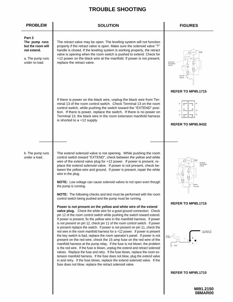
Part 2The pump runsbut the room willnot extend.
NOTE:
NOTE:
a. The pump runsunder no load.
Low voltage can cause solenoid valves to not open even thoughthe pump is running.
The following checks and test must be performed with the roomcontrol switch being pushed and the pump must be running.
b. The pump runsunder a load.
The extend solenoid valve is not opening. While pushing the roomcontrol switch toward "EXTEND", check between the yellow and whitewire of the extend valve plug for +12 power. If power is present, re-place the extend solenoid valve. If power is not present, check be-tween the yellow wire and ground. If power is present, repair the whitewire in the plug.
Power is not present on the yellow and white wire of the extendvalve plug. Check the white wire for a good ground connection. Checkpin 12 of the room control switch while pushing the switch toward extend.If power is present, fix the yellow wire in the manifold harness. If poweris not present on pin 12, check pin 11 of the room control switch. If poweris present replace the switch. If power is not present on pin 11, check thered wire in the room manifold harness for a +12 power. If power is presentthe key switch is bad, replace the room operator’s panel. If power is notpresent on the red wire, check the 15 amp fuse on the red wire of themanifold harness at the pump relay. If the fuse is not blown, the problemis the red wire. If the fuse is blown, unplug the extend and retract solenoidvalves. Replace the fuse and retry. If the fuse blows, replace the room ex-tension manifold harness. If the fuse does not blow, plug the extend valvein and retry. If the fuse blows, replace the extend solenoid valve. If thefuse does not blow, replace the retract solenoid valve.
RETRACT
WHITE
SOLENOID
BLACK
B A
B A
1113
2426
12 25
VALVE
B A
YELLOWWHITE
SOLENOIDEXTEND
B A
VALVE
REFER TO MP85.1715
REFER TO MP85.1715
REFER TO MP85.9432
13
11
12
26
24
25
If there is power on the black wire, unplug the black wire from Ter-minal 13 of the room control switch. Check Terminal 13 on the roomcontrol switch, while pushing the switch toward the "EXTEND" posi-tion. If there is power, replace the switch. If there is no power onTerminal 13, the black wire in the room extension manifold harnessis shorted to a +12 supply.
RED
FUSE15 AMP
4
+12 CABLE TOPUMP MOTOR
The retract valve may be open. The leveling system will not functionproperly if the retract valve is open. Make sure the solenoid valve "T"handle is closed. If the leveling system is working properly, the retractvalve is opening when the room switch is pushed to extend. Check for+12 power on the black wire at the manifold. If power is not present,replace the retract valve.

TROUBLE SHOOTING
SOLUTION FIGURESPROBLEM
MI91.215515MAY97
REFER TO MP85.1710
Part 3The pump runsbut the room willnot retract.
NOTE:
NOTE:
a. The pump runsunder no load.
The extend valve is open. Make sure the solenoid valve "T" handleis closed. Check for +12 power on the yellow wire at the manifold. Ifpower is not present, replace the extend valve.
Low voltage can cause solenoid valves to not open even thoughthe pump is running.
The following checks and test must be performed with the roomcontrol switch being pushed and the pump must be running.
b. The pump runsunder a load.
The retract solenoid valve is not opening. While pushing the roomcontrol switch toward "RETRACT", check between the black and whitewire of the retract valve plug for +12 power. If power is present, re-place the retract solenoid valve. If power is not present, check be-tween the black wire and ground. If power is present, repair the whitewire in the plug.
Power is not present on the black and white wire of the retractvalve plug. Check the white wire for a good ground connection. Checkpin 13 of the room control switch while pushing the switch toward retract.If power is present, fix the black wire in the manifold harness. If poweris not present on pin 13, check pin 11 of the room control switch. If poweris present replace the switch. If power is not present on pin 11, check thered wire in the room manifold harness for a +12 power. If power is presentthe key switch is bad, replace the room operator’s panel. If power is notpresent on the red wire, check the 15 amp fuse on the red wire of themanifold harness at the pump relay. If the fuse is not blown, the problemis the red wire. If the fuse is blown, unplug the extend and retract solenoidvalves. Replace the fuse and retry. If the fuse blows, replace the room ex-tension manifold harness. If the fuse does not blow, plug the retract valvein and retry. If the fuse blows, replace the retract solenoid valve. If thefuse does not blow, replace the extend solenoid valve.
ROOM EXTENSION
WHITE
RETRACT SOLENOID
BLACK
B A
B A
1113
2426
12 25
VALVE (1R)
B A
YELLOWWHITE
EXTEND SOLENOIDROOM EXTENSION
B A
VALVE (1E)
REFER TO MP85.1715
REFER TO MP85.1715
REFER TO MP85.9432
13
11
12 25
24
26
If there is power on the yellow wire, uplug the yellow wire from Ter-minal 12 of the room control switch. Check Terminal 12 on the roomcontrol switch, while pushing the switch toward the "RETRACT" po-sition. If there is power, replace the switch. If there is no power onTerminal 12, the yellow wire in the room extension manifold harnessis shorted to a +12 supply.
It is assumed at this point the leveling system operates correctly.
RED
FUSE15 AMP
4
+12 CABLE TOPUMP MOTOR

TROUBLE SHOOTING
SOLUTION FIGURESPROBLEM
MI91.216F08MAR00
REFER TO MP85.1715
REFER TO MP65.1715
REFER TO MP85.1715
Part 4
Part 5
Part 6REFER TO MP65.1715
The room moveserratically fromside to side (walk-ing) as it extendsor retracts.
The ends of theroom do not moveat an equal dist-ance from the ve-hicle.
Note :
Check that the pivot bracket is free to pivot. Check that the inner tubes
There are three possibilities :
A : An extend solenoid valve is leaking.B : A room extension cylinder has an internal leak.C : The manifold check valve is leaking.
likely the check valve.
Retract the room completely. Remove the hydraulic line for the capend of the cylinder at the manifold. Hold the hose end in an uprightposition. Press the rocker switch for that room to the "RETRACT"position.
If fluid flows from the manifold fitting, the extend solenoid valve needsto be changed.
the poppet and cap for burrs. The poppet should easily slide in thecap.
NOT lose the spring. Check for cuts on the poppet O-ring. Checkspect the manifold check valve. There is a spring below the cap. DOIf no fluid flows from either the hose end or the manifold fittings, in-
EXTENDSOLENOID
B A
B A
MANIFOLD
DETAIL B
CAP
POPPET
O-RING
SPRING
VALVE
YELLOWWHITE
B A
B A
VALVE
EXTENDSOLENOID
CHECKVALVE
MANIFOLDCHECKVALVE
The roomcreeps outafter beingretracted.
are free of paint or undercoating. Make sure the room is notbinding onthe top, bottom or sides. Check that the hoses between the rod end ofthe room cylinders and the synchronizing cylinder are the same lengthand diameter. Check that the hoses connected to the cap end of the room cylinders are the same length and diameter. Check that the roomextension mechanisms are not binding. Check that the awning is work-ing properly. If this is all OK Contact HWH Customer Service for assis-tance.
Due to variations such as weight and dimensions from end to end of aroom, it is possable for one end of the room to lead the other when theroom is moving. If the room seals properly top to bottom and end to end,there may not be a problem. Make the same checks as in part 4 then call HWH Customer Service for assistance.
The following deals with dual cylinder room extensions.
If the room creeps out 1 inch or less the problem is most
If only one side of the room creeps out, replace the room cylinder forthe side that creeps out. If both sides creep out, do the following tests.If the tests are not conclusive, replace the extend solenoid valve for the room. Check the o-rings at the end of the valve. If the o-rings aredamaged, there may be a problem with the manifold.

TROUBLE SHOOTING
SOLUTION FIGURESPROBLEM
MI91.217F08MAR00
REFER TO MP85.1715
AND MP45.9450
Part 7
Part 8The room stops need to be adjusted. See the adjustment section ofMP45.9412 and MP45.9415.
If the check valve is OK, or fluid flows from the hose end, the roomPart 6Continued
Check for external oil leaks. Replace the retract solenoid valve forthat room extension. This is the only possibility that would cause thisproblem.
The room doesnot seal tightlywhen fully re-tracted or ex-tended.
RETRACTSOLENOID VALVE
AB
BLACKWHITE
B A
The roomcreeps inafter beingextended.
extension cylinder should be replaced.
AND MP45.9436REFER TO MP45.9435
DUAL CYLINDER "RAIL"
"VERTICAL ARM"REFER TO MP45.9449
AND MP45.9448REFER TO MP45.9447
"VERTICAL ARM"
AND MP45.9436REFER TO MP45.9435
DUAL CYLINDER "RAIL"

CONTROL FUNCTIONS
CONTROL IDENTIFICATION
MP25.940530JAN97
CORPORATIONH
CAUTION!
CLEAR OF ROOM WHEN OPERATING.
UNDERSTAND OPERATOR’S MANUAL BEFOREUSING. KEEP PEOPLE AND OBSTRUCTIONS
HYDRAULIC ROOM EXTENSION
OFF
ON
RETRACT
HW R
EXTEND ROOM CONTROLSWITCH
KEY SWITCH
The KEY SWITCH controls power to the ROOMCONTROL SWITCH. When the KEY SWITCH is in the "ON"POSITION the room can be operated, and the key cannot beremoved. When the KEY SWITCH is in the "OFF" positionthe room cannot be operated, and the key can be removed.
The ROOM CONTROL SWITCHis a two position momentary switch. Pressing the switch inthe EXTEND POSITION will extend the room. Pressing theswitch in the RETRACT POSITION will retract the room. Re-leasing the ROOM CONTROL SWITCH will halt the operationof the room.
ROOM OPERATOR’S PANEL
KEY
KEY SWITCH: ROOM CONTROL SWITCH:

MP35.949007FEB00
MANUAL ROOM RETRACT PROCEDURE
OVERVIEWThe room can be retracted manually if a hydraulic or electricalfailure prevents the room from being retracted using the ROOMCONTROL SWITCH. For normal retract sequence see the
1. Retract jacks following the LEVELING SYSTEM RETRACTPROCEDURE.
2. Locate the HYDRAULIC PUMP/MANIFOLD unit.
3. Open the SOLENOID VALVES by turning the "T" HANDLEScounterclockwise.
come more difficult to turn as an internal spring is compressed.Be sure to open both valves completely (about six turns ofof "T" HANDLE).
are opened and internal pressure is released.
SOLENOID VALVES"T"HANDLES
(USE ONLY WHEN THE ROOM WILL NOT RETRACT WITH THE ROOM CONTROL SWITCH)
ROOM RETRACT PROCEDURE.
WINCH
WINCH STRAP
WINCH HANDLE
RATCHET LEVER
HOOK
MANUAL RETRACT WINCH
4. Locate the MANUAL RETRACT WINCH and connect it tothe room according to the vehicle manufacturer’s instructions.To extend the WINCH STRAP firmly grasp WINCH HANDLE,place RATCHET LEVER in its OFF position, and slowly rotatethe WINCH HANDLE counterclockwise, keeping a firm grip onthe handle. When enough WINCH STRAP is extended, place theRATCHET LEVER in its ON position and slowly rotate the WINCHHANDLE clockwise until the RATCHET LEVER locks.
5. Slowly winch the room in by turning the WINCH HANDLEclockwise. The RATCHET LEVER should produce a loud, sharp,clicking noise.
hydraulic fluid and make winching more difficult.
CAUTION:
ON
OFF
HYDRAULIC PUMP/MANIFOLD
NOTE : The room may move slightly as the SOLENOID VALVES
NOTE :
NOTE : Winching the room in quickly will raise pressure in the
NOTE : The "T" HANDLE may turn easily at first but will be-
6. When the room is fully retracted, engage the room lockingdevices. Leave the retract winch in place.
CAUTION: THE ROOM EXTENSION SOLENOID VALVE"T" HANDLES MUST BE IN THE OPEN POSITION WHEN THEMANUAL RETRACT WINCH IS ENGAGED.
7. The system should be repaired before using again.
CAUTION: THE MANUAL RETRACT WINCH IS EQUIP-PED FOR MANUALLY RETRACTING THE ROOM ONLY. ITIS NOT TO BE USED FOR LIFTING OR ANY OTHER AP-
When manually retracting the room, make sure thejacks are retracted before retracting the room.
PLICATION. HIGH FORCES ARE CREATED WHEN USINGA WINCH, CREATING POTENTIAL SAFETY HAZARDS. FAIL-URE TO FOLLOW ALL CAUTIONS AND INSTRUCTIONS MAYCAUSE FAILURE OF THE MANUAL RETRACT WINCH ORCONNECTIONS RESULTING IN DAMAGE OR PERSONALINJURY. MAINTAIN FIRM GRIP ON THE WINCH HANDLEAT ALL TIMES. NEVER RELEASE THE HANDLE WHEN RAT-CHET LEVER IS IN THE OFF POSITION AND THE WINCHIS LOADED. THE WINCH HANDLE COULD SPIN VIOLENTLYAND CAUSE PERSONAL INJURY. CHECK THE WINCH ANDSTRAPS FOR DAMAGE OR WEAR, AND CHECK FOR PRO-PER RATCHET OPERATION ON EACH USE OF THE WINCH.DO NOT USE IF DAMAGED OR WORN.
OPERATE THE MANUAL RETRACT WINCHBY HAND POWER ONLY. IF THE WINCH CANNOT BECRANKED EASILY WITH ONE HAND IT IS PROBABLY OVER-LOADED. IF WINCHING BECOMES TOO DIFFICULT STOPAND CHECK FOR OBSTRUCTIONS OR RESTRICTIONS ONTHE ROOM AND ROOM EXTENSION MECHANISM.
(WITH SOLENOID VALVES WITH VALVE RELEASE "T" HANDLES)

ML16463/MP45.943504JUN01
2. Loosen the extend valve "T" Handle.
3. Loosen the retract valve "T" Handle.
NOTE: Do not remove the caps from the new cylinder
12. Remove Hose A from the room extension manifold. Usea cap from the new cylinder to cap the fitting in the manifold.Direct Hose A into the fluid reservoir.
13. Close the extend and retract valve "T" handles.
14. Push and hold the room control switch to "EXTEND" untilthe new cylinder is fully extended plus five seconds.
IMPORTANT: DO NOT PULL THE CYLINDER ROD OUT OF THE NEW CYLINDER. INSTALL THE NEW CYLINDERWITH THE ROD RETRACTED AS IT WAS SHIPPED.
NOTE:
CAUTION:DO NOT TRY TO LINE THE ROOM
THE ROD IS EXTENDING.CYLINDER ROD UP WITH THE MOUNTING HOLE WHILE
15. Reattach Hose A to the room extension manifold.
22. Check all hose connections and mounting nuts and boltsfor tightness and leaks.
hose connections until you are ready to reattach the hoses. Save the caps.
11. Attach the hoses to the cylinder. Do not over tighten thehose ends. See MP45.9436 for tightening of hoses.
8. Remove the cylinder cap end mounting plate from the oldcylinder and attach it to the new cylinder.
10. Install the new cylinder in the room extension tube. DONOT install the two cylinder cap end mounting plate nuts andwashers.
The cap end of the cylinder will push the cylinder capend mounting plate off the room extension tube. This is ok.
17. Slide the cylinder rod through the rod mounting plate holeon the inner sliding tube. Install the nuts and lock washers onthe cylinder cap end mounting plate. Turn the cylinder rod inneradjusting nut into place and install the cylinder rod outer adjusting nut. Make the nut snug only, as a final adjustment will
6. Remove and cap the hoses at the end of the cylinder that is to be replaced.
IMPORTANT: Step 4 must be done to protect the room from
7. Remove the cylinder that is to be replaced from the room extension tube.
9. Install the inner out stop adjusting nut and lock washer completely onto the threaded rod of the new cylinder.
have to be made. Do this for the front and rear cylinders.
ROOM EXTENSION CYLINDER REPLACEMENTDUAL CYLINDER ROOM EXTENSION(WITH SYNCHRONIZING CYLINDER)
READINSTRUCTIONS
PROCEEDINGBEFORETHOROUGHLYSTOP
IMPORTANT: Do not reverse direction of the room untilthe room is fully extended or retracted.
IMPORTANT: The following instructions must be followed or air lock of the synchronizing cylinder and unsynchronized operation of the room cylinders may result causing damage to the room. Please read the instructions before replacing the cylinder. DO NOT reverse direction of the room unless the room is fully extended or retracted until the room is running properly.
1. Extend the room fully. There is an access hole on the inner sliding tube to access the cylinder rod mounting nuts. If the room cannot be fully extended the inner sliding tube access hole must be extended far enough to access the cylinder rod mounting nuts.
being damaged while bleeding air from and synchronizing the the room cylinders.
5. Remove the cylinder rod outer out stop adjusting nut for both the front and rear room cylinders.
IMPORTANT: BEFORE INSTALLING THE NEW CYLINDER, CLEAN ALL EXCESS OIL FROM THE ROOM EXTENSION TUBE. SWAB THE TUBE THOROUGHLY WITH A MILD SOLVENT AND RAGS. EXCESS OIL LEFT IN THE TUBE MAY LEAK OUT GIVING THE APPEARANCE OF A LEAKY CYLINDER OR HOSE CONNECTION.
16. Push and hold the room control switch to "RETRACT" until both cylinders are fully retracted, plus 5 seconds. Extend and retract the cylinders at least twice or until they are running fully synchronized. DO NOT reconnect the cylinders until they are running fully synchronized.
18. Push the room control switch to retract and hold until the room is fully retracted plus 5 seconds. Watch for excessive racking of the room. Some racking can occur do to air in the system. If the room starts to bind up, release the room control switch immediately. If the room does not bind up, proceed to Step 20. If the room is bound up, go to Step 19.
19. If the room is bound up, repeat Steps 4 and 5. Manually push the room out to its full extension. Now repeat Steps 15, 16, 17 and 18. If the room will still not run properly, contact HWH CORPORATION Customer Service at (800)321-3494 or at (563)724-3396.
21. With the room fully extended, check seals for proper compression. If the seal is not compressed or needs more compression, loosen the cylinder rod outer adjusting nut and tighten the cylinder rod inner adjusting nut. If the seal is compressed too much, loosen the cylinder rod inner adjusting nut and tighten the cylinder rod outer adjusting nut.
4. Remove the two nuts and washers from the cylinder cap end mounting plate for both the front and rear room cylinders.
20. Extend the room fully again. Do not reverse direction until the room is fully extended. Repeat retracting and extending the room several times being careful not to reverse directions until the room is fully extended or retracted.

CYLINDER REPLACEMENTDUAL CYLINDER ROOM EXTENSIONWITH SYNCHRONIZING CYLINDER
VIEW A VIEW BIN STOPADJUSTMENT
OUTER ROOMROOM EXTENSIONTUBEOUT STOP
ADJUSTMENT
INNER ROOMEXTENSIONTUBE
HOSE A
THIS LINEGOES TOTHE TANK
CAP THISFITTING
EXTEND SOLENOIDVALVE
RETRACT SOLENOIDVALVE
VALVE RELEASE"T" HANDLES
NOTE: ROD AND CAP END HOSE CONNECTIONSWILL BE THE SAME FOR MULTIPLE ROOMEXTENSIONS.
CYLINDER MOUNTINGPLATE NUT
ROD END 1/8"HIGH PRESSUREHOSE CONNECTION
CAP END
HOSECONNECTION
CYLINDERMOUNTING NUT
CYLINDERMOUNTINGPLATE NUT
CYLINDER MOUNTINGPLATE
VIEW B
OUTER OUT STOPADJUSTING NUT INNER OUT STOP
ADJUSTING NUT
VIEW A
ROOM EXTENSION MANIFOLD
ML16463/MP45.943630JAN01
3/16" HIGH PRESSURE HOSE
SY
NC
HR
ON
IZIN
G C
YLIN
DE
R
LOCK WASHERS(OLDER UNITS MAYNOT HAVE LOCK WASHERS
HOSE 4
3/16" HIGH PRESSURE HOSE
HOSE 1
HOSE 2
HOSE 3
IMPORTANT: HOSES 1 AND 2 BETWEEN THE CAP END OF THECYLINDERS AND THE PUMP MUST BE THE SAME LENGTH AND DIAMETER.
HOSES 3 AND 4 BETWEEN THE ROD END OF THE CYLINDERS AND THESYNCHRONIZING CYLINDER MUST BE THE SAME LENGTH HIGH PRESSUREHOSE. SOME EARLY SYSTEMS USED 1/8" HIGH PRESSURE HOSE. DO NOTMIX 1/8" HIGH PRESSURE AND 3/16 HIGH PRESSURE HOSE.
TIGHTENING AN EXISTING HOSE END, TIGHTEN THE HOSE ENDTHEN TIGHTEN THE HOSE END 1/3 TURN (2 FLATS). IFMAKE THE HOSE END SNUG (FINGER TIGHT) ON THE FITTING, TIGHTENING OF HOSE ENDS: IF TIGHTENING A NEW HOSE END,
TO SNUG PLUS 1/4 TURN (1FLAT).

ML18750/MP45.944704JUN01
ROOM EXTENSION CYLINDER REPLACEMENTDUAL CYLINDER VERTICAL ARM (WITH SYNCHRONIZING CYLINDER)(WITH ROOM EXTENSION MANIFOLD)
NOTE: Only the faulty cylinder is to be removed from the room extension arm.
7. Remove the four cylinder mounting bolts.
9. Install the new cylinder. First attach the proper hose to thecap end of the cylinder. Do not over tighten the fittings.
11. Install the cap end trunion bolts. Make sure the bolts areproperly seated into the groove at the cap end of the cylinder.
12. Attach the rod end hose to the cylinder. Do not over tighten the fitting. Wire tie the hose to the cylinder so it will not bind or be cut be the arm assembly.
13. Pull the arm assembly together and attach the rod end cylinder mounting nut to the arm.
14. Remove hose A from the pump. Remove the breather cap and direct hose A into the tank. Cap fitting A with a steel cap from the replacement cylinder.
15. Close the extend and retract valve "T" handles.
16. Push and hold the room control switch to "EXTEND" untilthe new cylinder is fully extended plus 3 to 5 seconds. Watch carefully that the cylinder does not extend too far.
17. Reattach hose A to fitting A.
18. Push and hold the room control switch to "RETRACT" until both arm assemblies are fully retracted. The new cylinder may not retract until the other arm is fully retracted.
19. Repeat extending and retracting the arms fully at least 3
20. Reattach the arms to the room with the pin plates.
more times or until the arms are completely synchronized. Do not go from "RETRACT" to "EXTEND" until the arms are fully retracted. Do not go from "EXTEND" to "RETRACT" until the arms are fully extended. Check that there are no leaks and that hose routings are ok.
2. Loosen the extend valve "T" handle.
3. Loosen the retract valve "T" handle.
23. Check again for leaks and hose routings. Clean any oilspills. Reinstall the coach interior.
READINSTRUCTIONS
PROCEEDINGBEFORETHOROUGHLYSTOP
existing hose end, tighten the hose end to snug plus 1/4tighten the hose end 1/3 turn (2 FLATS). If tightening anmake the hose end snug (finger tight) on the fitting, thenTightening of hose ends: If tightening a new hose end,
turn (1 FLAT).
IMPORTANT: The following instructions must be followed or air lock of the synchronizing cylinder and unsynchronized operation of the room cylinders may result causing damage to the room. Please read the instructions before replacing the cylinder. DO NOT reverse direction of the room unless the room is fully extended or retracted until the room is running properly.
NOTE: Do not remove the caps from the new cylinder hose connections until you are ready to reattach the hoses. Save the caps.
1. Extend the room fully. Support the outer edge of the room so that the room cannot sag when the room extension arms are disconnected.
4. Remove coach equipment and panels to gain access to the front and rear room extension arm assemblies. Protect the coach interior from possible oil spillage.
5. Remove the pin plate from both room extension arms. This will allow both arms to move separately from the room.
IMPORTANT: Step 5 must be done to protect the room from being damaged while bleeding air from and synchronizing the the room cylinders.
6. Remove and cap the hose from the rod end of the cylinder that is to be removed. Cut the wire ties holding the hose to the cylinder. There may be some pressure on the hoses.
8. Work the cylinder out of the arm assembly. Remove and cap the hose from the cap end of the cylinder.
IMPORTANT: DO NOT PULL THE CYLINDER ROD OUT OF THE NEW CYLINDER. INSTALL THE NEW CYLINDER WITH THE ROD RETRACTED AS IT WAS SHIPPED.
10. Install the cylinder into the arm assembly. Make sure the cap end hose is properly routed over the pivot pin as shown in the drawing.
21. Retract the room watching carefully that the room does not bind up. If the room binds up, DO NOT try to extend the room. Remove the pin plates and manually push the room out and support it. Repeat Steps 13 through 20. If the room will still not work properly, call HWH CORPORATION Customer Service at (800)321-3494 or at (563)724-3396.
22. If the room works properly extend and retract the room several times. Watch carefully that the room does not extend too far. Check that the room seals are properly compressed with the room extended. If the room needs to extend more, loosen the out stop cylinder adjustment jam nut. Use an allen wrench to turn the rod clockwise until the room is seated properly. Tighten the jam nut. If the room is extended too far, loosen the out stop cylinder adjustment jam nut and use an allen wrench to turn the rod counterclockwise until the room is properly seated. Tighten the jam nut.

ML18750/MP45.944802MAR00
ROD END
SYNCHRONIZING CYLINDER
TO SECOND ROOMEXTENSION VERTICAL
ARM ASSEMBLY
GROOVEFOR TRUNIONBOLT
CAP END CYLINDERMOUNTING NUT(NON-THREADED) ROD
REPLACEMENTCYLINDER
ROD END CYLINDERMOUNTING NUT(THREADED)
OUT STOP CYLINDERADJUSTMENT JAM NUT
CYLINDERMOUNTINGBOLT (2)
CAPEND PIVOT
PIN
CYLINDER MOUNTING BOLT (2)CAP END HOSE
PINPLATE
CAPEND
ROD END
IMPORTANT: HOSES 1 AND 2 BETWEEN THE CAP END OF THE CYLINDERS AND THE PUMP MUST BE THE SAMELENGTH AND DIAMETER.
HOSES 3 AND 4 BETWEEN THE ROD END OF THE CYLINDERS AND THE SYNCHRONIZING CYLINDER MUST BE THE SAME LENGTH OF 3/16" HIGH PRESSURE HOSE.
NOTE: NEW TRUNION BOLTS,MOUNTING NUTS AND JAMNUTS ARE SUPPLIED WITHTHE REPLACEMENTCYLINDER.
3/16" HIGH PRESSURE HOSEROD END OF CYLINDER
VALVE RELEASE"T" HANDLE
EXTEND SOLENOIDVALVE
FITTING A
HOSE A TO CAP END OFSYNCHRONIZINGCYLINDER
LEVELING SYSTEMMANIFOLD ORFITTINGS NOT SHOWN.
TO CAP END OF ROOMEXTENSION CYLINDER1/8" LINE
CAP END HOSE
CYLINDER REPLACEMENTVERTICAL ARM ROOM EXTENSIONWITH SYNCHRONIZING CYLINDER
RETRACTSOLENOIDVALVE
ROOM EXTENSION MANIFOLD
SOME OLDER SYSTEMS USED 1/8" HIGH PRESSURE HOSE.DO NOT MIX 1/8" HIGH PRESSURE AND 3/16" HIGH PRESSURE HOSE.
HOSE 1
HOSE 2
HOSE 3 HOSE 4

ML18751/MP45.944914SEP99
ROOM ADJUSTMENT PROCEDUREVERTICAL ARM ROOM EXTENSION
IMPORTANT: The room should be properly adjusted to fit the vehicle and seal correctly when extended and retracted beforeleaving the factory. Changing adjustments in the field may cause the room to work improperly or change the way paint linesmatch up.This sheet is meant to help make adjustments if a room is damaged or if a room extension mechanism is being replaced. Pleasecontact the vehicle manufacturer before making adjustment.
NOTE: If a room extension cylinder is replaced, only the room extended stop adjustment should need to be made.
VERTICAL ADJUSTMENT ROOM EXTENDED
IMPORTANT: This adjustment should never be changed. Only make this adjustment if the complete arm assembly is beingremoved and replaced.
1. Point B should move parallel to the vehicle floor at the same height as point A.
2. If Point B should be raised, loosen the chain adjustment jam nut and tighten the chain adjustment nut.
3. If Point B should be lowered, loosen the chain adjustment jam nut and loosen the chain adjustment nut.
4. Tighten the chain adjustment jam nut when the adjustment is complete.
VERTICAL ADJUSTMENT ROOM RETRACTED
Make this adjustment if the room is not properly positioned up and down with the coach when the room is fully retracted.
1. There are two possible ways to make this adjustment. The bearing adjustment block is either shimmed or it has slotted boltadjustments.
2. If the block is shimmed, add more shims as needed to lower the room. Remove shims if the room needs to be raised.
3. If the block has slotted bolts for adjustment, loosen the lower slotted bolt lock nut and turn the slotted end of the bolt clockwiseto raise the room and counter clockwise to lower the room.
4. Tighten the slotted bolt lock nut when the adjustment is complete.
ROOM EXTENDED STOP ADJUSTMENT
Make this adjustment if the room is not properly sealed or if the interior trim is not properly positioned when the room is fully ex-tended.
1. Loosen the extended stop jam nut.
2. Use a 5/16" hex key to turn the cylinder rod clockwise to move the room out or counter clockwise to move the room in.
3. Tighten the extended stop jam nut when the adjustment is complete.
ROOM RETRACTED STOP ADJUSTMENT
Make this adjustment if the room is not properly sealed or the outer room wall is not flush with the outside of the coach.
NOTE: The chain should not be slack in the retracted position. Readjust the retract stop bolts if the chain is loose.
1. Loosen the retract stop jam nuts.
2. Turn the retract stop adjustment bolts clockwise to adjust the room in and counter clockwise to adjust the room out. Both ad-justment bolts must be in contact with the stop when adjusted.
3. Tighten the retract stop jam nuts when the adjustment is complete.
Contact HWH CORPORATION Customer Service for assistance at 1-800-321-3494 or 319-724-3396.
(CHAIN ADJUSTMENT)
At no time, whether the room is extended or retracted, should the chain be be loose.
READINSTRUCTIONS
PROCEEDINGBEFORETHOROUGHLYSTOP

ML18751/MP45.945011SEP98
ROOM ADJUSTMENT PROCEDURESVERTICAL ARM ROOM EXTENSION
ROOM EXTENDEDSTOP ADJUSTMENT
CYLINDER ROD
EXTENDED STOPJAM NUT
DETAIL AEND VIEW
CHAIN
ROOM RETRACTEDSTOP ADJUSTMENTBOLTS (2)
RETRACT STOPJAM NUT
CHAINADJUSTMENTNUT
CHAINADJUSTMENTJAM NUT
VERTICALADJUSTMENTROOMEXTENDED
DETAIL A
POINT B
DETAIL B
ADJUSTMENTBLOCK WITHSLOTTEDADJUSTMENTBOLTS
SLOTTEDADJUSTMENTBOLTS (2)
LOWERSLOTTED BOLTLOCKNUTS (2)
SHIMS
ADJUSTMENTBLOCK WITHSHIMS
VERTICAL ADJUSTMENT ROOM RETRACTED
DETAIL B
POINT A

LF RF
LR RR
FR
ON
T
MP65.171520MAR01
(WITH SYNCHRONIZING CYLINDER)(WITH DUAL CYLINDER OR VERTICAL ARM ROOM EXTENSION)
200/210 SERIES LEVELING SYSTEMHYDRAULIC LINE CONNECTION DIAGRAM
SY
NC
HR
ON
IZIN
G C
YLIN
DE
R
HYDRAULIC CYLINDER
HYDRAULIC CYLINDER
STEEL TUBE
NOTE: STEEL TUBE IS USED ONDUAL CYLINDER "RAIL" ROOMEXTENSIONS ONLY.
ROD END CAP END
ROD END CAP END
STEEL TUBE
HIGHPRESSURE HOSE (B)
HIGH PRESSURE HOSE (B)
VIEW 1DUAL CYLINDER ROOM EXTENSION
ROD ENDHIGH PRESSUREHOSE CONNECTION(STEEL TUBE)
HOSE CONNECTIONCAP END
HOSE CONNECTIONS AT THEREAR OF DUAL CYLINDER "RAIL"ROOM EXTENSION
VIEW 1
(A)
(A)
THE LINES (B) BETWEEN THE ROD ENDOF THE HYDRAULIC CYLINDERS AND THESYNCHRONIZING CYLINDER MUST BE THESAME LENGTH AND DIAMETER
THE LINES (A) BETWEEN THE CAPEND OF THE HYDRAULIC CYLINDERSAND THE TEE MUST BE THE SAMELENGTH AND DIAMETER
IMPORTANT:
PRESSURE
VALVERELEASE"T" HANDLE
RETURN
TO SYNCHRONIZING CYL.(ROD END OF ROOM CYLINDERS)
CAP END
PRESSURE
LEFTFRONTJACK
RIGHTFRONTJACK
RETURN
NOTE: DIFFERENT TYPESOF HOSE, ESPECIALLYHIGH PRESSURE HOSE, HAS BEEN USED. THE PRINTING ON A 1/8" OR 3/16"HOSE BEING REPLACED
LEFTREARJACK
RIGHTREARJACK
MUST MATCH THE ORIGINALHOSE. ALL HWH 1/4" HOSEIS THE SAME.
VALVESOLENOIDRETRACT
EXTENDSOLENOIDVALVE

HYDRAULIC FLOW DIAGRAM
MP65.945512AUG97
FIXED TOVEHICLE
FRONT CYLINDER
VERTICAL ARM OR DUAL CYLINDER ROOM EXTENSION
REAR CYLINDER
VEHICLEFIXED TO
STATIONARY POSITION
PRESSURE
RETURN
EXTENDVALVE
RETRACTVALVE
SYNCHRONIZING CYLINDER
SYNCHRONIZINGVALVE
SYNCHRONIZINGVALVE
WITH SYNCHRONIZING CYLINDER

ELECTRICAL SCHEMATIC
VALVE SWITCH
PUMPRELAY
RETRACT
EXTEND
FUSED ACCESSORY
STAINLESS STEELGROUND STUD
JOYSTICK
10 AMP
"JACKS DOWN" LIGHT
(10-15AMP)
(RED) 6120(WHITE) 6230(BLUE) 6820(BROWN) 7699
(GREEN) 4000
(ORANGE) 1000
(GRAY) 2000
(BLACK) 3000
+12 -(RED) 6120
(YELLOW) 5000(BLACK) 5100
(BLUE) 6820
200/210 SERIES BI-AXIS LEVELING SYSTEM
WITH HYDRAULIC ROOM EXTENSION SYSTEM
NEGATIVE SIGNAL WHENA JACK IS DOWN.
SWITCHESJACK WARNING
SWITCHROOM CONTROL
(RED) 6810
EXTENDRETRACTPUMP
GROUND
KEY SWITCH
(WHITE) 6231
(GRAY) 8601
ROOM EXTENSIONWIRING HARNESS ROOM OPERATOR’S
PANEL
LEVELING SYSTEMWIRING BUNDLE
PUMP/MANIFOLDASSEMBLY
PUMP RELAY CONTACTS
+ 12 CHASSIS BATTERY
JOY STICKLIGHT PANEL
BROWN IS A
BLUE WIRE ISHOT WHEN PANEL IS ON.
(PURPLE)
(PURPLE) 6121
**NOTE:
*NOTE:
(BROWN) 7699
15 AMP
+12
M
6121
08MAR00MP85.1505
NOTE: THE (4) DIGIT WIRE NUMBERSUPERSEDES ANY AND ALLWIRE COLORS.

ELECTRICAL CONNECTION DIAGRAMBI - AXIS VALVE WITH ROOM EXTENSION
(BLUE) 6820
PUMP RELAY
(RED) 6810
(GRAY) 8601
* FUSE MAY BE REQUIRED - CHECK APPLICABLE CODE
A GROUND CABLE THAT IS TO BE ATTACHED TO THE GROUND STUD.PUMP MUST BE MOUNTED SOLIDLY TO FRAME. SOME PUMPS HAVE
WIRES CANNOT BE REVERSED
15 AMPFUSE
* FUSE
BATTERY
HARNESSROOM EXTENSION
DIAGRAMMANIFOLD WIRING
SEE ROOM EXTENSION
GROUND
-
(RED) 6810
+
(GRAY)
LEVELING
HARNESSSYSTEM
(BLUE)
(BLUE) 6820
CONNECTION
FUSE 10 AMP
DIAGRAM
WIRES ARE LABELED, RELAY
PUMP RELAY HARNESS
(WHITE) 6230
FROM VALVE *
ELECTRICALSEE GROUNDING
(GRAY) 8601
PUMP RELAY
FUSE15 AMP
SWITCHED +12SUPPLY TO ROOMEXTENSIONOPERATOR’S PANEL(RED) 6810
4
2
1
3
RELAYCONTROL WIREFROM JOYSTICK
+12 FROM LEVELING SYSTEMCONTROL PANEL
PUMP RELAY
+12 CABLEFROM ENGINEBATTERY
RELAY CONTROLWIRE FROM ROOMEXTENSIONOPERATOR’S PANEL(GRAY) 8601
VAVLE
+12 CABLE TOPUMP MOTOR
8601
6820
6231
(WHITE)6245
14MAR00MP85.1710
NOTE: THE (4) DIGIT WIRE NUMBERSUPERSEDES ANY AND ALL WIRE COLORS.
NOTE: 8600 AND8601 WIRES ARESWITCHED GROUND
8600
8600
* NOT USED WITH A 210 SYSTEM -8600 WIRE IS IN THE MAIN HAR-NESS FOR THE LEVELING SYSTEM

GROUNDING
ELECTRICAL CONNECTION DIAGRAM
+-
3/8-16 NUT
LOCK WASHER (3 USED)
WHEN POWER UNIT IS MOUNTED TO VEHICLEFRAME VIA WELDED CHANNEL, CONNECTGROUND CABLE STRAP TO EITHER PUMPMOUNTING BOLT POSITION AS SHOWN. A3/8" INTERNAL STAR LOCKWASHER MUST BEUSED BETWEEN PUMP CHANNEL/GROUNDING
WIRE TERMINALS/NUT.
PUMP MOUNTING CHANNEL
GROUND CABLESTRAP
3/8" INTERNAL STAR
GROUNDING STUD
PUMP MOUNTING
STUD, GROUNDING STUD/GROUND CABLESTRAP TERMINAL AND BETWEEN GROUND
(NOT USEDON SOME PUMPS)
HARNESSROOM EXTENSION
TO ROOM EXTENSIONSOLENOID VALVES
AB
1E
1R
(BLACK) 5100
(YELLOW) 5000
ROOM EXTENSION EXTENDSOLENOID VALVE (1E)
WIRE SETSARE LABELED FOREACH SOLENOID.
VIEW FROM PUMP END
WHITE WIRES TO GROUND STUD
SEE PUMP RELAYCONNECTION
DIAGRAM
ROOM EXTENSION MANIFOLD
TO PUMP RELAY
PUMP RELAYHARNESS FROM
BI-AXIS VALVE WITH ROOM EXTENSION
10 AMP FUSE
SEE PUMP RELAY
DIAGRAMCONNECTION
LEVELING SYSTEMHARNESS
(BLUE) 6820
(WHITE) 6230
VALVE *
DIAGRAMCONNECTION
SEE PUMP RELAY
SEE ABOVE GROUNDING
DIAGRAM
GROUNDING AND MANIFOLD WIRING
NOTE:
B A
(WHITE) 6245(WHITE) 6245
B
A
B
A
SPRINGCAP
DETAIL AO-RING
POPPET
2E
2R
3E
3R
ROOM EXTENSIONRETRACT SOLENOIDVALVE (1R)
ROOM EXTENSIONHARNESS (ONEHARNESS PER ROOM EXTENSION)
NOTE: MORE THAN ONE MANIFOLD MAY BE STACKEDON TOP OF THE POWER UNIT.
ROOM EXTENSION MANIFOLD
NOTE: THERE IS ONE PAIR OF ROOM EXTENSION SOLENOIDVALVES PER ROOM EXTENSION.
MANIFOLD CHECK VALVE(SEE DETAIL A)
"T" HANDLE
62316245
08MAR00MP85.1715
NOTE: THE (4) DIGIT WIRE NUMBERSUPERSEDES ANY AND ALLWIRE COLORS.
* NOT USED WITH A 210 SYSTEM

15JAN99MP85.9432
ELECTRICAL CONNECTION DIAGRAMROOM EXTENSION SYSTEM
1213
11
2526
24
ROOM EXTENSION
(REAR VIEW)
OPERATOR’S PANEL
KEY SWITCH
+12 FROM
ROOM EXTENSIONHARNESS
PANEL CONNECTION
SEE CONNECTION DIAGRAMGROUNDING AND MANIFOLD WIRING
ANDCONNECTION DIAGRAM PUMP
RELAY WIRING
PUMP RELAY -
TO GROUNDSTUD -
WHITE
11-BLACK
WHITE
BLACK
* THE (RED) 6810 WIRE SHOULD BE CONNECTEDTO THE SWITCHED SIDE OF THE RELAY.SEE THE PUMP RELAY WIRING DIAGRAM.
ROOMCONTROLSWITCH
NOTE: FOR VEHICLES WITH MORE THAN ONE ROOM EXTENSION, EACHROOM EXTENSION WILL HAVE A SEPARATE OPERATOR’S PANELAND ROOM EXTENSION HARNESS.
26
1112
2425
13
DETAIL A
12
11
13
25
24
26
(WHITE) 6230
(RED) 6810 *25+26 - (GRAY) 860113 - (BLACK) 510012 - (YELLOW) 5000
NOTE: THE (4) DIGIT WIRE NUMBER SUPERSEDES ANY AND ALL WIRE COLORS.
24