february 1, 2000 - dot.state.oh.us€¦ · polyurethane insulation with mastic coating: 2-in...
TRANSCRIPT

Thank you for making us your chosen tank supplier!
40 years in the tank business has taught us that proper installation is the key to long-term, trouble-free tank service. Please study and use the information contained in this manual. It will make a tremendous difference in the useful life of your tank.
INSTALLATION Guide
866-590-6845
PROTECT YOUR WARRANTY - READ THESE INSTRUCTIONS

TABLE OF CONTENTS
2
General Information…....………………..……………...…………………………………………………......................……………………………..3 Product Specifications……..…………………..…………………………...…………...........................................................……………..…4 Receiving Merchandise….….................................…..……….…...............……...…………………………………..……..…………….……5 Returning Merchandise….……….............................…...............…………….…………………………………….………...………………….5 Tank Location……………..……..…………………..…………………………...…………...........................................................……………..…5 Off-Loading Instructions….…...…………..…….........................................…………………………………..……………………………….. 6 SAFE-Surge® Emergency Air Surge Protection……….................………..............................................………………..……8 Recommended Torque Values…...………………...........................................………….....................................…………………..9 IMFO® Flange Fitting Assembly…………………...............…………………………….......................................………………………10 B.O.S.S.® Fitting Assembly………………………................………………….....................................……………………………….………11 Bulkhead Fittings………….……………………………............……..........................................……......................…………………………13 Bolted Flange Fittings………………………...............…………......................................……………………………………………………...14 Stainless Steel Fittings………………………….…....................................................…………………………………………………….…....15 Fill Line Assemblies…….………………….….……....................................................…………….......................…………………………16 Self Aligning Universal Ball Dome Fittings……................………...................................................……...……...…..............17 Reverse Float Liquid Level Gauge....................................................................................................................................18 Sight Glass Liquid Level Gauge.........................................................................................................................................19 Bellows Transition Fitting…………………..…………….......................................................................................………………….20 Flexible Connections…...………………………....................................................................................……………...……...…………23 FRP Ladder Installation….....................................................................................................................................................26 Restraint Systems………..........................................................................................................................................................30 Horizontal Tank Stands….......................................................................................................................................................31 Start-up Checklist and Safety Tips……….…………...............………………………………………………...…………..…………………32 Maintenance Items………………………………….…………...............………………………………………………...…………..…………………33 Annual Tank Inspection Checklist…….............................................................................................................................34 Limited Warranty....................................................................................................................................................................35 Notes…………………….....................................................................................................................................................…………..36

GENERAL INFORMATION Installation Videos: Please visit http://www.polyprocessing.com/technical-resources/
installation-manuals-videos/ for installation videos and a digital copy of the Installation Guide.
Installation: Hydro test (water test) tank system for 24 hours before introduction of chemi-cal. If necessary, remove all test water to prevent reaction with chemical stored.
Heat Maintenance Systems: Two thermostats are furnished, one for control and one for high limit; heating requirements vary depending on maintenance temperature, ambient temperature, and wind conditions.
Polyurethane Insulation with Mastic Coating: 2-in nominal thickness, density range 2 – 2.8 lbs /cubic foot, R value ≥ 6.3 / inch, mastic coasting is white acrylic vinyl.
Nominal / Working Capacity: Calculated vertical tank capacity is to top of straight side-wall.
ASTM D 1998 Standard: All vertical, IMFO®, and SAFE-Tank® systems greater than 500 gal-lons are manufactured in accordance with ASTM D 1998 standards.
Gallonage Markers: Approximate indicators are not intended for precise measuring or metering. Fill vertical tanks and cones only to top of sidewall.
Support hoses, piping and valves independent of tank sidewall and dome. Flexible connections must be used to protect your tank warranty (See page 23)! Shield all fittings, valves, and piping from physical impact and to protect personnel from chemical spray or release.
Tank Foundation:
Place tank on a clean, smooth, and properly designed concrete foundation or in PPC approved support assembly. Ensure NO trash of any kind is trapped between the tank and its foundation or support.
IMFO® tank – use a PPC polyethylene pad or a monolithic concrete pad with finished edges to elevate bottom of tank above primary floor surface. The pad must be at least 4-in thick to provide full clearance for the IMFO® flange. At the IMFO® location, the straight wall of the tank must align with the straight wall of the foundation to prevent stress. DO NOT use a polyethylene pad when storing fluids with a specific gravity greater than 1.65.
General guideline to accommodate restraint clips and ladders:
Make foundation 2-ft larger in diameter than the diameter of the tank. If using the IMFO® tank, provide a “notch” in the foundation to accommodate the
IMFO® outlet. If tank will have fixed ladder, include adequate landing for the ladder to prevent
injury.
3
WARNING: Failure to provide proper foundation support constitutes a misuse of the tank and will void your warranty!

4
PRODUCT SPECIFICATIONS Temperature: Tank specific gravity ratings are based on continuous product operating
temperature of 100°F. For temperatures between 100°F and 150°F, please contact Customer Support.
Pressure: Polyethylene tanks are designed and rated for atmospheric pressure only. Proper venting alleviates pressure or vacuum from developing as the tank is filled and emptied. See venting table below for proper configuration.
Flexible Connections allow for tank expansion / contraction and reduce pump / piping vibration stresses. Flexible connections are required on any fitting connection on the lower 1/3 sidewall of the tank to preserve your warranty. See page 23. Shield all fittings, valves, and piping from physical impact to protect personnel from chemical spray or release.
Tank Dome Loading: DO NOT stand or work on top of tank. The tank surfaces are flexible and slippery and a dangerous fall could occur. There is no weight or load rating for the domes of tanks.
Venting Requirements for Polyethylene Tanks
Mechanical Pump Fill Pneumatic Fill
IF ≤ 1000 gallons IF—Vent length ≤ 3 feet IF—Vent length ˃ 3’ and ≤ 30’ IF—Scrubber Application
Vent size should equal
size of largest fill or discharge fitting
AND—Vent screen mesh size ≥
1/4” or no screen used
And—3 or less 90 elbows with no other restrictions or reduction in
pipe size
Vent pipe size throughout scrubber system CANNOT be reduced!
Centerline of dispersion pipe not to be submersed ˃ 6 inches
IF ˃ 1000 gallons Emergency Pressure Relief Cover Required
Emergency Pressure Relief Cover Required
Perforated dispersion pipe must be same diameter or larger, as vent. Sum of perforations ≥ cross sectional area of pipe
Vent size should exceed the largest fill or
discharge fitting by 1 inch min
Tanker Discharge
Inlet/Fitting Size
Minimum Vent Size
Tanker Discharge
Inlet/Fitting Size
Minimum Vent Size
Tanker Discharge
Inlet/Fitting Size
Minimum Vent Size
2” 2” 4” 2” 2” 6” 2” 2” 6”
3” 2” 6” 3” 2” 6” 3” 2” 8”
3” 3” 6” 3” 3” 8” 3” 3” 10”
Rev. Nov. 2006
For detailed venting guidelines, please visit our Technical Resources at www. polyprocessing.com
(2) 2-in vents DO NOT EQUAL 4-in venting capacity

5
RECEIVING MERCHANDISE RECEIVING:
Inspect immediately upon receipt for obvious damage, defects, or missing parts and accessories.
Parts and accessories are often secured boxed and shipped loose from the tank. Locate and open packages to account for all parts using the packing slip.
Note damage/discrepancies on the driver’s copy and the packing slip and have the driver initial.
Immediately notify your Authorized Distributor or Poly Processing Company of any problems.
DAMAGED/MISSING MERCHANDISE: Report damaged/missing merchandise within THREE (3) working days to ensure your claim. Your authorized distributor and/or Poly Processing Company can assist you with this process.
Poly Processing Customer Support
Monroe, Louisiana French Camp, California . 866.590.6845 877.325.3412
RETURNING MERCHANDISE To return unused merchandise for proper credit:
Contact your authorized distributor or Poly Processing Customer Support and obtain a PPC Return Merchandise Authorization (RMA) number. Have your packing slip available for any needed information.
Use the RMA number on all return shipping paperwork and all correspondence.
Return the merchandise prepaid. Freight collect shipments will be refused.
Upon receipt, PPC will inspect the merchandise and issue appropriate credit. A restocking fee may be assessed, particularly on products “made to order”.
To ensure employee safety, Poly Processing Company will not accept used tanks at its facilities.
Tank Location Locate the tank wisely: Minimal employee and equipment traffic near tank Safe distance away from heat and flames Ease of future maintenance and inspection Ability to remove and replace the tank cost effectively in the future, i.e. Do not trap the tank
in a building or by other equipment Provide flat, level and smooth monolithic foundation, adequate for the weight of the chemical
to be stored Utilize secondary containment of proper size and chemical resistance to comply with local,
state and federal regulations. The Safe Tank system is designed to provide a minimum of 110% secondary containment

off-loading INSTRUCTIONS Keep personnel clear of tank, rigging, and lift equipment! Improper and unsafe
unloading can result in property damage, serious injury, or death.
DO NOT STAND OR WORK ON TOP OF TANK. The tank surfaces are flexible and slippery, which could cause a dangerous fall. The tank dome is not load rated, as it is not required per ASTM D D1998-06; therefore, it cannot be guaranteed that the top of the dome can support the weight of personnel.
Whether unloading or moving, the tank must be fully drained before lifting.
Use of Lifting Lugs:
Consult the tank drawing for the proper number of molded-in lifting lug sets to use during a lift. Two molded lugs constitute a set. See picture below.
Position the boom of the crane directly over the centerline of the tank lying on its side near the dome (top). Use all lifting lug sets as the lift points (the holes in the lifting lugs have a 1-3/8-in diameter and are spaced 8-in from side to side). Thread a bolt through each eyelet that is large enough to take up as much of the hole as possible to improve lifting control. Ensure each bolt and cable have a lifting capacity of a minimum 3000 pounds. (INSULATED TANKS: Extreme care should be taken to ensure that during the attachment of the bolts and cables from the boom position to the lifting lugs, none come in contact with the tank, causing damage to the foam surface. To prevent this from happening, attach pieces of cardboard to the dome, near the lifting lug positions to protect the sensitive surface area from any contact during the lifting process. Once you have confirmed that all Lifting Lugs are properly attached and the slack in the cables have been removed, it is now an appropriate time to cut away the protective wrap and wooden cradle before starting the lifting process)
Slowly begin to raise the tank into an upright position. Take extreme care in balancing the weight of the tank. (INSULATED TANKS: The bottom portion of the foam area of the tank base will be crushed if it is allowed to tilt and sit on its own weight)
Once the tank is positioned in its upright position, lift it up and lower the tank back onto the bed of the trailer. This will remove the tension from the cables temporarily to provide the opportunity to reposition the clamps and cables and find the true balance point positions. (INSULATED TANKS: Remove protective wrap and wooden cradle and discard)
Raise the boom slowly until all slack has been removed from all lifting cables and you are assured the weight of the tank is now balanced. Lift the tank high enough to clear the trailer. You are now positioned to transport the tank to its final position.
IMPORTANT NOTE: If the tank has an IMFO, before it is allowed to sit flat on its own weight at any point during the off-loading process, a block (preferably a 12-in 4x4) must be set underneath the IMFO base to keep it off the ground. This is necessary to keep the IMFO from being damaged (by design, it sits lower than the flat bottom of the tank).
2 LUGS = 1 SET
6
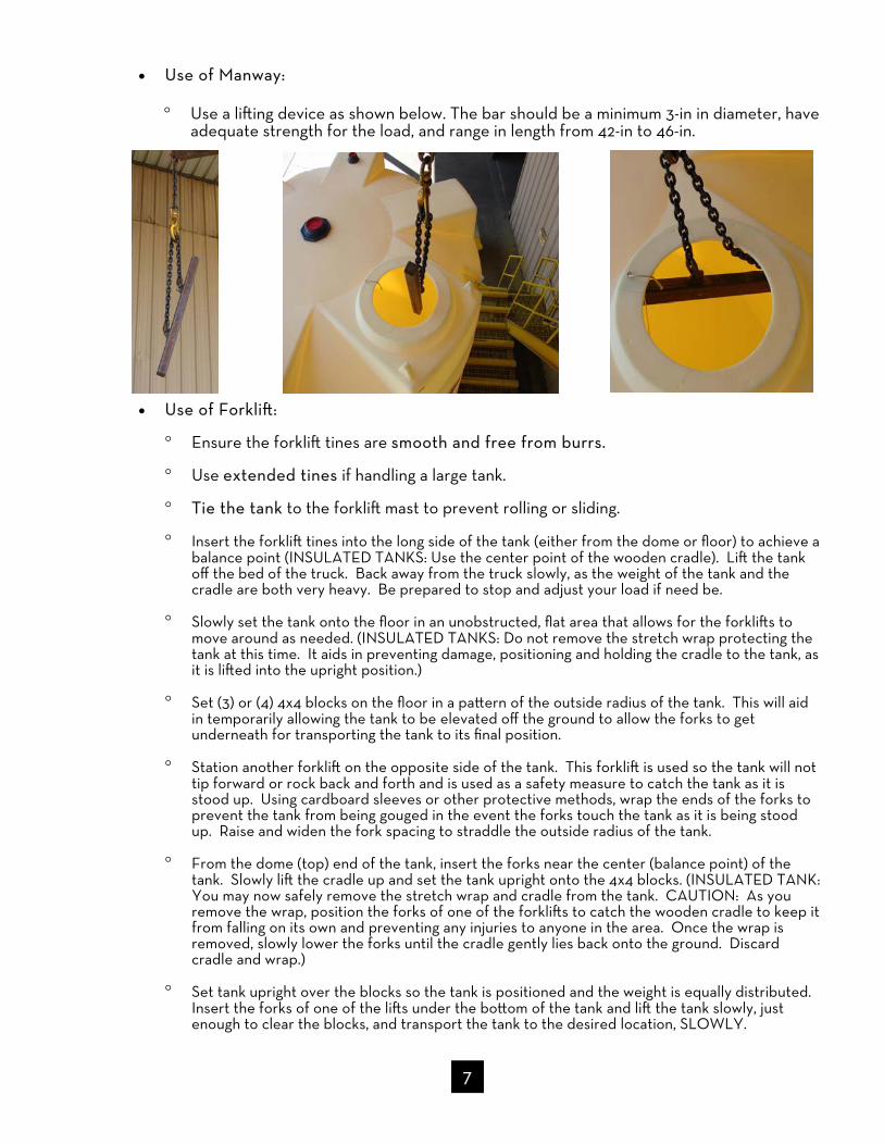
Use of Manway:
Use a lifting device as shown below. The bar should be a minimum 3-in in diameter, have adequate strength for the load, and range in length from 42-in to 46-in.
Use of Forklift:
Ensure the forklift tines are smooth and free from burrs.
Use extended tines if handling a large tank.
Tie the tank to the forklift mast to prevent rolling or sliding.
Insert the forklift tines into the long side of the tank (either from the dome or floor) to achieve a balance point (INSULATED TANKS: Use the center point of the wooden cradle). Lift the tank off the bed of the truck. Back away from the truck slowly, as the weight of the tank and the cradle are both very heavy. Be prepared to stop and adjust your load if need be.
Slowly set the tank onto the floor in an unobstructed, flat area that allows for the forklifts to move around as needed. (INSULATED TANKS: Do not remove the stretch wrap protecting the tank at this time. It aids in preventing damage, positioning and holding the cradle to the tank, as it is lifted into the upright position.)
Set (3) or (4) 4x4 blocks on the floor in a pattern of the outside radius of the tank. This will aid in temporarily allowing the tank to be elevated off the ground to allow the forks to get underneath for transporting the tank to its final position.
Station another forklift on the opposite side of the tank. This forklift is used so the tank will not tip forward or rock back and forth and is used as a safety measure to catch the tank as it is stood up. Using cardboard sleeves or other protective methods, wrap the ends of the forks to prevent the tank from being gouged in the event the forks touch the tank as it is being stood up. Raise and widen the fork spacing to straddle the outside radius of the tank.
From the dome (top) end of the tank, insert the forks near the center (balance point) of the tank. Slowly lift the cradle up and set the tank upright onto the 4x4 blocks. (INSULATED TANK: You may now safely remove the stretch wrap and cradle from the tank. CAUTION: As you remove the wrap, position the forks of one of the forklifts to catch the wooden cradle to keep it from falling on its own and preventing any injuries to anyone in the area. Once the wrap is removed, slowly lower the forks until the cradle gently lies back onto the ground. Discard cradle and wrap.)
Set tank upright over the blocks so the tank is positioned and the weight is equally distributed. Insert the forks of one of the lifts under the bottom of the tank and lift the tank slowly, just enough to clear the blocks, and transport the tank to the desired location, SLOWLY.
7

8
SAFE-Surge® EMERGENCY AIR SURGE PROTECTION To install: 1. SAFE-Surge® lids are HEAVY. Use lifting equipment to place the SAFE-Surge® lid over
the tank manway. 2. Rotate the lid until the warning label is next to the edge of the tank. 3. Secure the lid with the polyethylene bolts provided. 4. Make certain the movement of the center cap of the lid is unrestricted and able to open
to relieve pressure build-up in the tank.
DO NOT BIND OR RESTRICT MOVEMENT OF THIS ARM AND ASSEMBLY
WARNING: SAFE-Surge® lids are heavy (22 lbs.) and awkward! DO NOT attempt to use a ladder for installing the SAFE-Surge® lid. The ladder may become unstable and lead to a fall or injury! Use lift equipment appropriate for work environment or use scaffolding and hoisting equipment.
Make sure Warning label is secure and visible on lid.

RECOMMENDED TORQUE VALUES and Techniques ALWAYS: Lubricate bolts with anti-seize compound prior to installing nuts. Tighten the nuts in a crisscross pattern using a torque wrench. Tighten in 5 ft. lb.
increments.
9
Fitting Torque
PVC Bolted Flange 15-20 ft. lbs.
CPVC Bolted Flange 15-20 ft. lbs.
PP Bolted Flange 15-20 ft. lbs.
Stainless Steel Bulk Head 25 ft. lbs.
B.O.S.S.® Fitting 15-20 ft. lbs.
Bellows Transition Fitting 15-20 ft. lbs.
IMFO® Flange Fitting 15-20 ft. lbs.
Flexible Connections 15-20 ft. lbs.
PVC Bulkhead Fitting 1/4 turn beyond hand tight
ILLUSTRATION
The following tightening sequence is suggested for the flange bolts.
1
3 8
4
6
5
7
2
4
2
1
3
or
CORRECT way to cover all threads with thin layer of
thread sealant
INCORRECT
Method for applying thread sealant to threaded fittings:

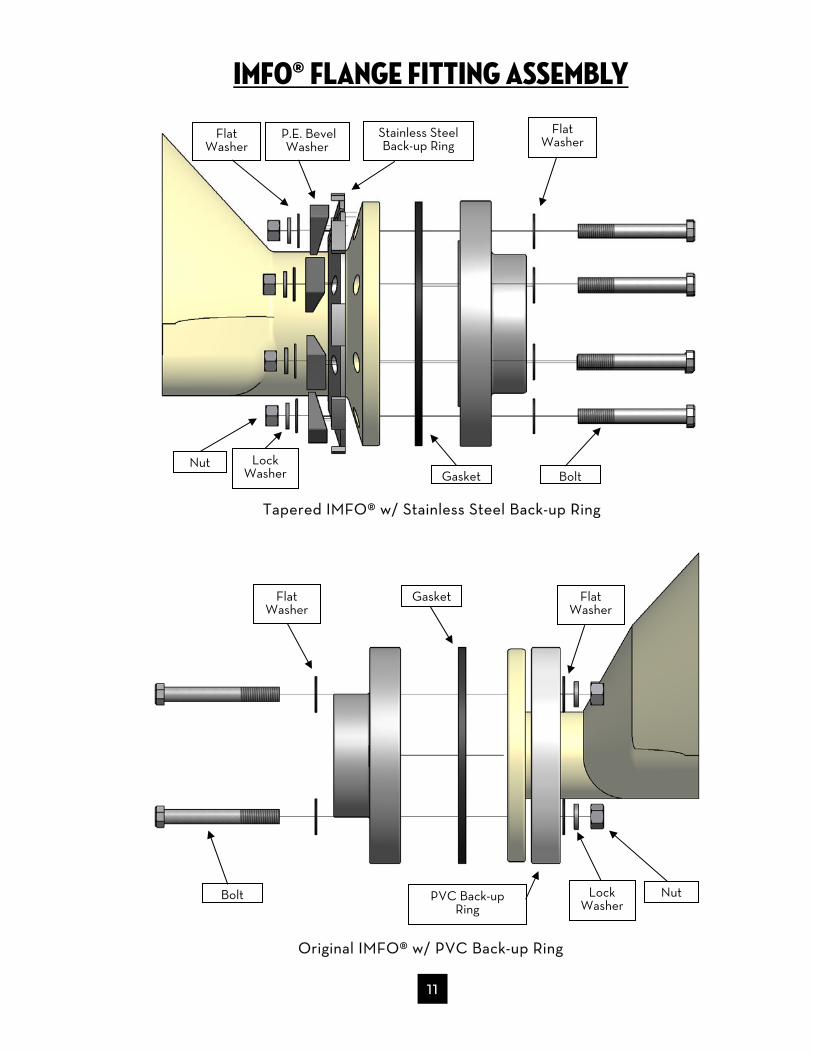
Imfo® flange fitting assembly The IMFO® (Integrally Molded Flanged Outlet) is assembled at the PPC plant sites and
hydro tested to ensure proper seal. There are two types of IMFO® back up rings.
DO NOT disassemble the factory installation. If field replacement is necessary, use
picture and exploded view on the next page as a guide. Protect the IMFO® flanged nozzle when storing and installing. When storing, the tank
can be stood upright with adequate blocking or laid on its side and chocked to prevent rolling.
10
Tapered IMFO® w/ Stainless Steel Back-up Ring Original IMFO® w/ PVC Back-up Ring
CORRECT STORAGE. Notice clearance of flange above the floor.
4-in Min Clearance
Imfo® flange fitting assembly
11
Original IMFO® w/ PVC Back-up Ring
Tapered IMFO® w/ Stainless Steel Back-up Ring
Flat Washer
Nut
Gasket Flat Washer
PVC Back-up Ring
Lock Washer
Nut Lock Washer
Flat Washer
Flat Washer
Gasket
P.E. Bevel Washer
Stainless Steel Back-up Ring
Bolt
Bolt

B.O.S.S.® (Bolted One-Piece Sure Seal) fitting assembly
1. Using the gasket as a template, mark the bolt holes on the outside of the tank. 2. Drill the center hole and stud holes with a 1/4-in pilot bit. Be precise with the layout and
drilling of the tank as the fitting requires close tolerances. 3. Drill out the pipe fitting hole using a hole saw. Please note that the hole to be drilled into
the tank may be smaller than the hole in the outer plate that was used as a template. The hole drilled should be only slightly larger than the outside diameter of the pipe fitting.
4. Next drill out the stud bolt holes using a 9/16-in drill bit for the 1/2-in diameter studs. 5. Clean and bevel all drilled and cut holes on the inside and outside of tank surfaces. 6. Install the fitting and gasket from the inside of the tank. Inside of tank must be flat and
smooth. If the inner surface is uneven or lumpy, the inner wall must be faced smooth using a drill with sandpaper attached to a steel plate. All surfacing must be done in a circular manner.
7. Slide the flange onto the stud bolts that are protruding on the outside of the tank. 8. Place the washers and nuts on the stud bolts. Tighten the nuts in a crisscross pattern
using a torque wrench. Tighten until the gasket is fully compressed (approximately 15-20 ft. lbs. on a torque wrench).
9. Inspect the fitting. The gasket should be compressed and the flange should conform to the wall of the tank.
10. Hydro test the tank for at least 24 hours prior to loading with chemical.
12
1” 1 1/2”
2” 2 5/8”
3” 3 5/8”
Fitting size Hole saw size
Coupler
Flat Washer
Nut Lock Washer
Tank Wall
Gasket
B.O.S.S. Fitting
Vanstone Ring

BULKHEAD FITTINGS
1. Slide the gasket over the body of the fitting. 2. From inside the tank, insert fitting body into hole in tank sidewall. 3. Lubricate threads on fitting body with thread sealant and install large nut on the outside
of the tank. 4. Hand tighten plus 1/4 turn with a wrench. Most Bulkhead fittings use left hand threads. 5. Do not allow fitting body to slip or spin when tightening to prevent the gasket from
creeping between the fitting and the tank wall. 6. Inspect gasket for creep. If found, loosen nut and perform steps 4 & 5 again. 7. When installing a pipe or flange adapter into the BHF, do not allow BHF to slip and do
not over tighten. 8. Hydro test the tank for a minimum of 24 hours before placing into chemical service. Bulkhead fittings and tank sidewall restrictions:
Fitting Body
Nut
Gasket
13
BHF size Hole saw size
1/2” 1 3/8”
3/4” 1 5/8”
1” 1 7/8”
1 1/4” 2 3/8”
1 1/2” 2 5/8”
2” 3 1/4”
3” 4 1/2”
4” 5 3/4”
BOLTED FLANGE FITTINGS
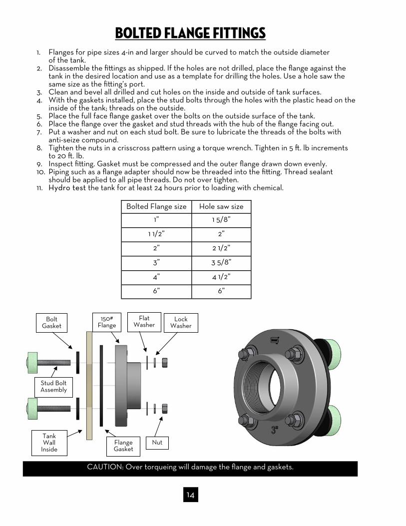
1. Flanges for pipe sizes 4-in and larger should be curved to match the outside diameter of the tank.
2. Disassemble the fittings as shipped. If the holes are not drilled, place the flange against the tank in the desired location and use as a template for drilling the holes. Use a hole saw the same size as the fitting’s port.
3. Clean and bevel all drilled and cut holes on the inside and outside of tank surfaces. 4. With the gaskets installed, place the stud bolts through the holes with the plastic head on the
inside of the tank; threads on the outside. 5. Place the full face flange gasket over the bolts on the outside surface of the tank. 6. Place the flange over the gasket and stud threads with the hub of the flange facing out. 7. Put a washer and nut on each stud bolt. Be sure to lubricate the threads of the bolts with
anti-seize compound. 8. Tighten the nuts in a crisscross pattern using a torque wrench. Tighten in 5 ft. lb increments
to 20 ft. lb. 9. Inspect fitting. Gasket must be compressed and the outer flange drawn down evenly. 10. Piping such as a flange adapter should now be threaded into the fitting. Thread sealant
should be applied to all pipe threads. Do not over tighten. 11. Hydro test the tank for at least 24 hours prior to loading with chemical.
CAUTION: Over torqueing will damage the flange and gaskets.
14
Tank Wall
Inside
Stud Bolt Assembly
Bolt Gasket
Flange Gasket
150# Flange
Flat Washer
Nut
Lock Washer
Bolted Flange size Hole saw size
1” 1 5/8”
1 1/2” 2”
2” 2 1/2”
3” 3 5/8”
4” 4 1/2”
6” 6”

STAINLESS STEEL FITTINGS 1. Disassemble the stainless steel fitting by removing the nuts from the stud bolts. Remove
the 1/8-in thick stainless steel outer plate. Set the remainder of the fitting aside along with the nuts and washers.
2. Using the outer plate as a template, mark the bolt holes on the outside of the tank. 3. Find the center of the large “pipe fitting” hole by drawing an “X” through the center of
the bolt holes. 4. Drill out the pipe fitting hole using a hole saw. Please note that the hole to be drilled into
the tank may be smaller than the hole in the outer plate that was used as a template. The hole drilled should be only slightly larger than the outside diameter of the pipe fitting.
5. Next drill out the stud bolt holes using a 9/16-in drill bit for the 1/2-in diameter studs. 6. Clean and bevel all drilled and cut holes on the inside and outside of tank surfaces. 7. Install the fitting and gasket from the inside of the tank. 8. Slide the outer plate onto the stud bolts that are protruding on the outside of the tank. 9. Replace the washers and nuts on the stud bolts. Tighten the nuts in a crisscross pattern
using a torque wrench. Tighten until the gasket is fully compressed (approximately 25-ft. lbs. on a torque wrench).
10. Inspect the fitting. The gasket should be compressed and the outer stainless steel plate should conform to the wall of the tank.
11. Hydro test the tank for at least 24 hours prior to loading with chemical.
15
STAINLESS STEEL Coupler
STAINLESS STEEL Full Nipple Lock
Washer
Outer Plate
Stud Bolt
Nut Gasket Back Plate
Tank Wall Inside
Rhino SS BHF size
(Nipple Style)
Hole saw size
1/2” 1 3/8”
3/4” 1 5/8”
1” 1 7/8”
1 1/2” 2”
3” 3 5/8”
4” 4 3/4”
2” 2 1/2”
Rhino SS BHF size
(Coupler Style)
Hole saw size
1/2” 1 3/8”
3/4” 1 5/8”
1” 1 7/8”
1 1/2” 2 1/4”
3” 4 1/2”
4” 5”
2” 2 5/8”

FILL LINE ASSEMBLIES
Fill line assemblies are available in 3 styles: internal, external and combination (see example drawings below, number of pipe supports may vary).
Your tank system may be equipped with a drop pipe stabilizer bracket which is typically shipped loose and requires simple installation. The internal pipe support is typically preinstalled at the manufacturing facility.
16
Stabilizer Bracket
Interior Fill Line Combo Fill Line exterior Fill Line
Adjustable Nut for
Positioning
Internal Pipe
Support

Adjustable Ball
Retaining Ring
Nut
Lock Washer
O-Ring Gasket
self aligning universal ball dome fittings The Self Aligning Universal Ball Dome fittings are designed for use only on tank domes. DO NOT USE ON THE SIDEWALL OF THE TANK! There are two styles of Ball Dome fittings: Bulkhead Fitting Style and Bolted Flange Style.
1. Do not stand on tank dome when installing dome fittings. Use portable ladders, scaffold-ing, or personnel lifts with proper fall protection.
2. Install the bulkhead fitting or flange portion of the ball dome fitting according to instructions found on page 13 or page 14.
3. Thread piping into the threaded ball of the fitting. Use thread sealant. 4. Adjust vertical alignment:
a. Gently loosen the ball retainer ring located on top of the fitting ball using a large blunt screw driver or punch and hammer.
b. Adjust piping to desired angle. c. Tighten retainer ring with blunt screw driver or punch and hammer taking care not to
over-tighten!
17
BHF Style
Flange Style
Flat Washer
WARNING: Do not stand or work on top of tank. The tank surfaces are flexible and slippery and could cause a dangerous fall to occur. There is no weight or load rating for the domes of tanks.
UBD size (BHF Style)
Hole saw size
1” 3 1/4”
2” 4 1/2”
3” 5 3/4”
UBD size (Flange Style)
Hole saw size
2” 3 1/2”
3” 4 1/2”
4” 5 3/4”

Reverse float liquid level gauge
DO NOT USE GLUE FOR ANY OF THE FOLLOWING STEPS! 1. Retrieve exterior portion of gauge that is shipped loose. 2. Thread rope through:
a. Threaded nipple (for the tank dome fitting) b. Over the top of the rollers in the first 90 degrees elbow c. Short horizontal pipe d. Over the top of the rollers in the second 90 degrees elbow
3. Attach rope to level indicator (note: length of rope must be determined during installation). 4. Install threaded nipple into dome fitting. 5. Attach first 90 degree elbow. 6. Attach short pipe. 7. Attach second 90 degree elbow. 8. Place level indicator into clear pipe. 9. Attach clear pipe to 90 degree elbow. 10. Attach clear pipe to external pipe stabilizer.
Periodically lubricate rollers to ensure proper operation!
18
4-in Perforated Sewer Pipe
2-in Sch 80 Pipe Th’d (1) End
Fitting as req’d
2-in x 4-in Sch 80 Th’d Adpt
4-in x 4-in Sewer Bushing
1/8-in Dia Yellow Polypropylene
Rope
Float
Pipe Stabilizer
2-in Sch 40 Clear Tube
2-in Sch 40 Pipe Cap
Level Indicator
2-in Sch 40 90o Elbow W/ Roller Pulley

Sight glass liquid level gauge
19
DO NOT USE SIGHT GLASS GAUGES IN SULFURIC ACID OR OTHER DANGEROUS CHEMICAL SERVICE! Use only in benign applications such as water.
1. Sight glass assemblies are completed at the factory and shipped separate of the tank to pre-vent damage.
2. Separate the unions on either end of the assembly. 3. Screw the two short nipples, with 1/2 of the union, into the sight glass fittings at the top and
bottom of the tank. 4. Rejoin the unions on the assembly and tighten carefully. 5. If necessary, install additional valves and/or piping. 6. HYDRO TEST FOR 24 HOURS before placing into chemical service!
Special Notes:
The clear tubing will discolor over time due to chemical and UV attack. WARNING: In the event the liquid level gauge is damaged or leaks, it is very likely the entire
contents of the tank will be lost! Use only in benign applications such as water.
WARNING: Do not use sight gauges in sulfuric acid or other dangerous chemical service. Loosening of any fittings associated with a sight glass liquid level gauge, may result in a chemical spill and/or property damage, bodily injury, or death.

bellows transition fitting
Introduction and Warning
These instructions are intended to make your transition fitting installation and maintenance trouble free. Read them carefully and identify all parts before starting your installation. Follow all general safety practices and your company specific safety practices.
Inner and Outer Tank Alignment
The design of the alignment sleeve is to ensure that your tank arrives without any alignment issues. In the event that a misalignment does occur during shipment or set up, please contact the manufacturer for instructions.
WARNING: The SAFE-Tank® system is designed to provide a minimum of 110% secondary containment. Once the transition fitting is installed, a leak in the inner tank will result in product collection between the inner and outer tank. If this product is not drained off prior to breaking the seals of the transition fitting, serious property damage, injury or death may occur. Great care must be taken to protect people and property when working with a transition fitting.
20
Nuts and Alignment Sleeve

Filling and Testing Inner Tank
1. Attach flexible connection assembly to inner tank fitting. (Do not install bellows at this time.) If the connection is a solvent weld, allow adequate dry time.
2. Cap or plug all inner tank sidewall fittings and fill the inner tank with water to top knuckle. Make sure you provide support to the flexible connection during the hydro test. Allow the tank to remain full for 12 to 24 hours. This allows: a. The inner tank to fully seat itself in the outer tank. b. The inner tank to fully expand without stressing the inner tank flange and recently
installed flexible connection assembly. c. Detection of any leaks in the inner tank created during shipping and handling. d. Detection of any leaks between the inner tank flange and recently installed nipple.
3. Determine if any leaks are occurring by using the outer tank access hole to look for water collecting in the space between the inner and outer tank. Correct any problems. Leak cannot always be visually detected once the transition fitting is installed!
Assembly of the Transition Fitting (Video Demonstration can be found at http://www.polyprocessing.com/technical-resources/installation-manuals-videos/ )
Tightening/torque criteria:
Steel bolts/stud bolts: progressively tighten in crisscross pattern to 20 ft lbs max. PVC BHF Nut: Hand tighten plus 1/4 turn with a wrench.
Loose parts boxed for shipment
Remove nuts and alignment sleeve before beginning
Confirm proper alignment
Glue PVC pipe/flexible connection assembly to inner tank fitting
Install gasket for bellows Install bellows and SS Back Rings
Glue BHF Install Outer Face Plate
and SS Back Ring Tighten nut on BHF (left hand threads)
Finished Assembly
21

Bellows Transition Fitting Exploded View
22
Flexi Joint
Flat Washer
Nut
Lock Washer
Spacer Ring
Outer Tank Wall
Nut
Flat Washer
Lock Washer
Spacer Ring
Flat Washer
Lock Washer
Nut Flat
Washer Gasket
Back-up Ring
Gasket Back-up Ring
Flat Washer
Lock Washer PE Plate

23
FLEXIBLE CONNECTIONS
Flexible connections are required on fittings installed on the lower 1/3 of the tank sidewall to allow the tank to expand and contract and to protect the tank from pump vibrations.
Install flexible connection in accordance with the specific manufacturer’s installation guidelines:
The “breech opening” in the piping for the flexible connection should be within 1/8-in of the relaxed length of the flexible connection.
Flexible connections are not to be used for correcting piping misalignment. The flexible connection and mating flanges must be installed in a centered and neutral position.
Attach only FULL FACE flanges to the flexible connection. They are not designed to attach directly to tank wall.
Ensure adequate clearance between bolt ends for full use of flexible connections. Torque to 20 ft. lbs using crisscross tightening pattern. Provide pipe support adjacent to the flexible connection.
Flexible Connection Minimum Specifications:
Axial Compression ≥ 1.5” Axial Extension ≥ 0.625” Lateral Deflection ≥ 0.750” Angular Deflection ≥ 14° Torsional Rotation ≥ 4°
Installation of flexible hose connections:
Use thread sealant for pipe thread preparation. Support hose adequately but do not restrict its ability to move in horizontal directions.
Flexible connection installed on IMFO® flange
(Optional Flange Mate Shown)
Butterfly Valve
Flexible connection installed near tank sidewall
(Optional Flange Mate Shown)
Polyethylene Encapsulated
Stud Bolts Flexible connection
Flexible connection

FLEXIBLE CONNECTIONS Proper Installation of Pipe Supports
Pipe supports positioned CORRECTLY: pipe support must be placed after the flexible connection to allow the tank to properly expand and contract.
Pipe supports positioned INCORRECTLY: pipe support incorrectly placed before the flexible connection does not allow the tank to properly expand and contract, which can cause the piping or tank to crack over time.
24

FLEXIBLE CONNECTIONS Proper Installation of Flexijoints
Flexible connections aligned CORRECTLY: pipe system with the Flexijoint is aligned in a straight manner, which allows for proper expansion and contrac-tion of the two connecting tanks.
Flexible connections aligned INCORRECTLY: the Flexijoint should not be used to accommodate misaligned piping. This will limit the ability of the Flexi-joint to function correctly and possibly damage the joint itself.
25
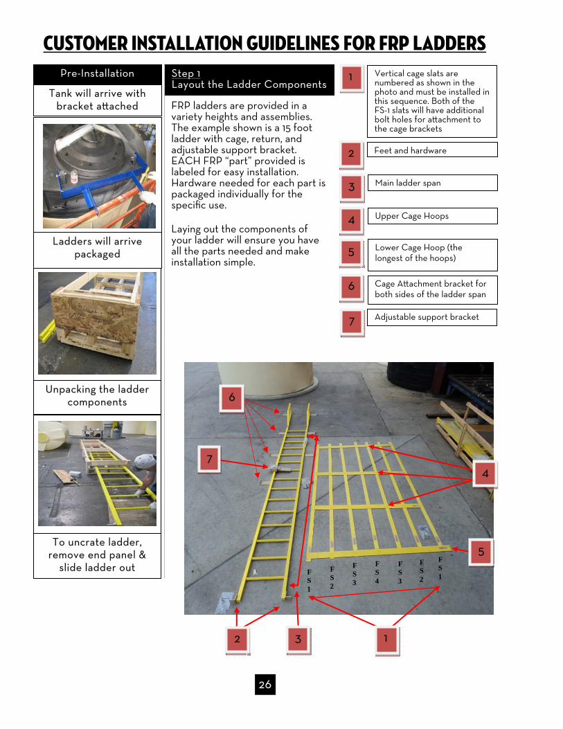
Customer installation guidelines for frp ladders
Ladders will arrive
packaged
Unpacking the ladder components
Tank will arrive with bracket attached
Pre-Installation
Feet and hardware
Main ladder span
Upper Cage Hoops
Vertical cage slats are numbered as shown in the photo and must be installed in this sequence. Both of the FS-1 slats will have additional bolt holes for attachment to the cage brackets
Lower Cage Hoop (the longest of the hoops)
Step 1 Layout the Ladder Components
1
2
3
4
5
6 Cage Attachment bracket for both sides of the ladder span
Adjustable support bracket 7
To uncrate ladder, remove end panel &
slide ladder out
4
2 3 1
7
6
5
FRP ladders are provided in a variety heights and assemblies. The example shown is a 15 foot ladder with cage, return, and adjustable support bracket. EACH FRP “part” provided is labeled for easy installation. Hardware needed for each part is packaged individually for the specific use.
Laying out the components of your ladder will ensure you have all the parts needed and make installation simple.
26
FS 1
FS 2
FS 3
FS 4
FS 3
FS 2
FS 1
27
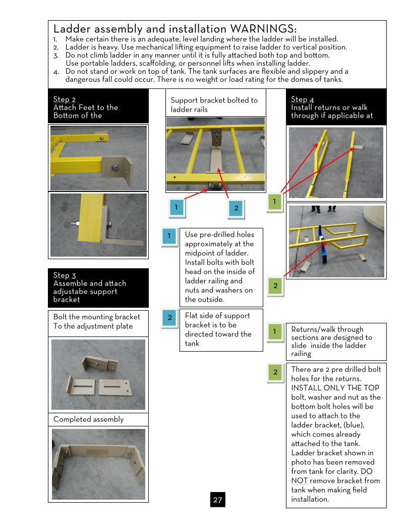
Step 2 Attach Feet to the Bottom of the
Step 3 Assemble and attach adjustabe support bracket
Bolt the mounting bracket To the adjustment plate
Completed assembly
Support bracket bolted to ladder rails
Use pre-drilled holes approximately at the midpoint of ladder. Install bolts with bolt head on the inside of ladder railing and nuts and washers on the outside.
Flat side of support bracket is to be directed toward the tank
2
1
1
2
Step 4 Install returns or walk through if applicable at
Returns/walk through sections are designed to slide inside the ladder railing
1
2 There are 2 pre drilled bolt holes for the returns. INSTALL ONLY THE TOP bolt, washer and nut as the bottom bolt holes will be used to attach to the ladder bracket, (blue), which comes already attached to the tank. Ladder bracket shown in photo has been removed from tank for clarity. DO NOT remove bracket from tank when making field installation.
2
1
Ladder assembly and installation WARNINGS: 1. Make certain there is an adequate, level landing where the ladder will be installed. 2. Ladder is heavy. Use mechanical lifting equipment to raise ladder to vertical position. 3. Do not climb ladder in any manner until it is fully attached both top and bottom. Use portable ladders, scaffolding, or personnel lifts when installing ladder. 4. Do not stand or work on top of tank. The tank surfaces are flexible and slippery and a
dangerous fall could occur. There is no weight or load rating for the domes of tanks.
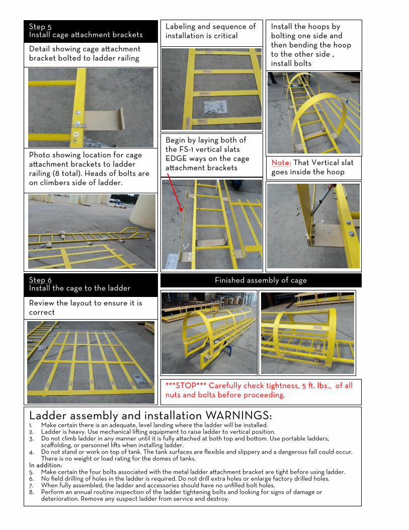
Step 5 Install cage attachment brackets
Detail showing cage attachment bracket bolted to ladder railing
Photo showing location for cage attachment brackets to ladder railing (8 total). Heads of bolts are on climbers side of ladder.
Step 6 Install the cage to the ladder
Review the layout to ensure it is correct
Labeling and sequence of installation is critical
Begin by laying both of the FS-1 vertical slats EDGE ways on the cage attachment brackets
Install the hoops by bolting one side and then bending the hoop to the other side , install bolts
Note: That Vertical slat goes inside the hoop
Finished assembly of cage
***STOP*** Carefully check tightness, 5 ft. lbs., of all nuts and bolts before proceeding.
Ladder assembly and installation WARNINGS: 1. Make certain there is an adequate, level landing where the ladder will be installed. 2. Ladder is heavy. Use mechanical lifting equipment to raise ladder to vertical position. 3. Do not climb ladder in any manner until it is fully attached at both top and bottom. Use portable ladders,
scaffolding, or personnel lifts when installing ladder. 4. Do not stand or work on top of tank. The tank surfaces are flexible and slippery and a dangerous fall could occur.
There is no weight or load rating for the domes of tanks. In addition: 5. Make certain the four bolts associated with the metal ladder attachment bracket are tight before using ladder. 6. No field drilling of holes in the ladder is required. Do not drill extra holes or enlarge factory drilled holes. 7. When fully assembled, the ladder and accessories should have no unfilled bolt holes. 8. Perform an annual routine inspection of the ladder tightening bolts and looking for signs of damage or
deterioration. Remove any suspect ladder from service and destroy.

29
Step 7 Attach the ladder to the tank using the metal ladder bracket
CAUTION Lift the ladder by mechanical means such as a fork lift and align the pre drilled holes in the top of the ladder railing with the holes in the tank’s metal ladder bracket. The tabs of the ladder bracket go inside the ladder rails.
Step 8 Make Adjustments
Plumb the ladder. Mark the location for the anchor bolts. Drill anchor holes and attach ladder to foundation.
After the ladder has been aligned and securely attached at top and bottom, adjust to support bracket so that the flat side touches the outer wall of the tank, tighten support bracket bolts.
Bolt the ladder and bracket to one another using the 3/8” x 2 ½” bolts. Torque to 5 ft. lbs.
Drawing Example
REV. 8/27/2010

30
Restraint Systems
Wind and seismic restraint systems are governed by state and local code. Consult your local code for requirements.
1. Restraint Clips a. Space equally around circumference of tank. If tank operating temperatures exceed 100°
F, contact Customer Support for proper clip placement. b. Allow minimum of 1-in clearance between tank and back of clip to accommodate tank
expansion. c. Attach the clips to the foundation with appropriate fasteners (customer supplied).
2. Cable Assembly a. Place cable assembly over the tank with the cable sling or tension ring at the top center
of the dome. b. Pass each cable leg over the upper shell knuckle through the Edge Softener. c. Place the wire rope thimble in the eye-nut (Style A) or the hole provided in the restraint
clip (Style B) and loop the cable around the thimble. d. Install the wire rope clips by forming a loop with the cable end. See instructions included
with wire rope clips. e. After the cable is attached to the restraint clips, the excess cable slack must be removed.
Cable tension should only be snug enough to secure the Edge Softeners against the upper tank knuckle. Excessive cable tension should be avoided as it may cause undue stress and deformation to the tank.
f. After cable tension is properly adjusted, the wire rope clips should be checked for proper tightening.
3. Periodic Inspection a. Periodically check cables and wire rope clips to ensure proper but not excessive tension b. Adjust if necessary, following steps e and f above.

31
HORIZONTAL TANK STANDS
NOTE: Horizontal tank stands are designed to be located on level concrete foundations or other approved surfaces. Tank stands must be bolted to the foundation. Stands for larger horizontal tanks are shipped “knocked down” to minimize freight. Small tank stands do not require assembly. If working with a stand shipped “knocked down”:
1. Check to ensure that the following components have been received: a. Vertical leg units b. Side angle braces c. One bag containing stainless steel tabs and bolts
2. Assemble vertical leg units to side angle braces. Square unit and tighten all bolts. If working with any stand:
3. Place the stand on a level foundation. 4. Anchor stand to foundation with appropriate bolts. (customer supplied) 5. Center tank and skid on stand.
a. With a forklift, crane, or other lifting device, place the tank and skid onto the stand, being careful not to damage the skid. Protect hands and fingers from pinch points during this step.
b. Locate holes in the top of the stand and center the tank and skid unit on the stand. 6. Install the stainless steel tabs and bolts using the holes in the top of the stand per photo
below. 7. Hydro test the tank for at least 24 hours prior to loading with chemical.
Tank Size No. Upright Leg Units
No. Side Angle Braces
No. of Bolt Assemblies
No. of Tabs
520 gal. 4
1,000 gal. 2 4 14 4
1,950 gal. 3 8 22 6
stand is welded together
Finished Assembly Position SS Tabs
Place Tank on Stand Assemble Side Angle Braces
Note: These “knocked down” assembly instructions apply only to horizontal tank stands from Monroe, Louisiana.

Start-up checklist
Hydro test (water test) tank system for 24 hours before introduction of chemical. Remove all test water from tank to prevent reaction with chemical stored.
Follow chemical manufacturer’s best practices for product being stored.
Confirm compatibility of tank, fittings, bolts and gaskets before filling tank with chemical.
Obtain, utilize and retail Material Safety Data Sheets (MSDS) for the chemical being stored.
Make sure vent size is not reduced. Inspect vent lines for obstruction. Verify vent size is adequate to prevent over pressurization of the tank. Follow Poly Processing’s venting guidelines. See page 4.
Ensure flexible connections are installed on all lower sidewall fittings and that they are installed correctly. See page 23.
Ensure there is adequate support of valves, piping and hoses and that support is installed correctly. See page 24
Ensure valves are installed as close to the tank as possible. Be sure valves can be easily accessed.
Check ladders at top and bottom for stability and safety.
Label tank with the appropriate warning label for the chemical being stored. Do not remove Poly Processing’s general warning labels.
Safety tips
DO NOT STAND OR WALK ON TOP OF TANK. The tank surfaces are flexible and slippery and a dangerous fall can occur. There is no weight or load rating for the domes of tanks.
Tanks are confined spaces. Follow proper entry procedures based on local, state and federal regulations. Establish and adequate retrieval plan.
Maintain guards, shields, barriers and walkways to protect tank, fittings and piping from impact and to protect personnel from chemical release.
32
WARNING: Failure to adequately support tank, fittings, valves, piping, and hoses and to protect them from impact can cause chemical release resulting in serious injury or death.

Maintenance Items
Conduct annual inspections of the tank. See page 34 for inspection guidelines.
Inspect gaskets for signs of fatigue. Replace as necessary.
Check bolt torque on fittings and adjust as needed.
Look for signs of stress cracking on both the exterior and interior surfaces of the tank. Look for hazing or a spider web type look.
Check flexible connections to make sure they are functioning properly, are not in a bind, and are not worn or leaking.
Check threaded couplers to make sure they cannot be turned by hand.
Check for leaks at the threaded couplers. This can be caused by over tightening and can take months or years to finally give.
Inspect valves for leaks and make sure they are working properly.
Inspect vent lines for any restrictions or obstructions.
Inspect ladders, brackets, stabilizers and stands for signs of corrosion.
33

34
Annual tank inspection checklist Even relatively new polyethylene tanks should receive routine and careful visual inspections. These inspection guidelines should be followed at least annually to ensure the safety of personnel and the preservation of the chemical stored. The tank should be replaced if it displays stress cracking, crazing, or embrittlement.
Empty the tank. Neutralize any chemical remaining. Thoroughly clean the exterior and interior of the tank. A dirty tank cannot be properly inspected.
Examine the exterior and the interior of the tank for cracking, crazing and brittle appearance.
Pay particular attention to areas around fittings and where different portions of the tank converge into one another. In other words, give special attention to “corners” where sidewall and dome meet and where sidewall and bottom meet.
If a confined space entry is not feasible, use a bright light source to inspect the tank interior from the manway opening. An interior inspection is essential because stress cracks normally show up on the inside of a tank before appearing on the outside.
Don’t forget to inspect areas of the tank that never actually come in contact with the chemical stored. With fume-emitting chemicals, oxidation and resulting embrittlement of the dome can occur without any actual contact with the chemical stored.
Inspect fittings, flexible connection hoses, and gaskets for leaks and signs of general corro-sion or deterioration.
Inspect vents and fume scrubbers to ensure adequate venting for pressure and vacuum. Ensure end of scrubber piping is never submerged in more than 6-in of liquid.
Confirm that filling of the tank from tanker trucks is not causing over pressurization and not ending with a line purge that “balloons” the tank. See “VENTING” on page 4.
Confirm secondary containment is appropriate for chemical stored, adequate in size, and in good repair.
WARNING: Failure to follow these inspection guidelines and take necessary corrective actions can result in unintended chemical release causing serious property damage, injury, or death. Chemical fumes may be present in the area of the manway opening. A tank is a confined space. Do not enter tank without a confined space entry and retrieval plan. Use lift equipment and/or fall protection to prevent fall into or away from tank. DO NOT STAND OR WORK ON TOP OF TANK. Dome surfaces are flexible and slippery. The dome may be embrittled. A dangerous fall could occur.

35
Limited Warranty
POLY PROCESSING COMPANY PRODUCT WARRANTY PERIOD
CROSSLINKED POLYETHYLENE TANKS for all suitable applications except those listed below 5 yrs.
IMFO® tanks storing SODIUM HYPOCHLORITE 9-15 wt% XLPE w/ OR-1000™, 1.9 spg rating
5 yrs.
NON-IMFO® tanks storing SODIUM HYPOCHLORITE 9-15 wt% 1,000 gallons and larger: XLPE w/ OR-1000™, 1.9 spg rating Less than 1,000 gallons: XLPE 1.9 spg rating
3 yrs.
Tanks storing SULFURIC ACID ≥ 80% concentration SAFE-Tank® to 8,700 gallons: XLPE w/ OR-1000™, 2.2 spg rating Vertical tanks 1,000-6,600 gallons: XLPE w/ OR-1000™, 2.2 spg rating Vertical tanks less than 1,000 gallons: XLPE 1.9 spg rating
3 yrs.
Tanks storing HYDROCHLORIC ACID ≤ 37% concentration XLPE w/ OR-1000™, 1.9 spg rating
5 yrs.
Tanks storing HYDROCHLORIC ACID ≤ 37% concentration XLPE 1.9 spg rating
3 yrs.
LINEAR POLYETHYLENE TANKS for all suitable applications except Sodium Hypochlorite 9-15 wt%; Sulfuric Acid and Hydrochloric Acid of any concentration
3 yrs.
The limited warranty described herein is Poly Processing Company’s sole warranty and the complete, final and exclusive statement of the terms of the warranty. Owner and/or user may not rely on any oral statement or representations. This warranty is neither assignable nor transferable. Issued: July 2012
Poly Processing Company’s warranty consists of repair or replacement of defective product. Owner and/or user may be requested to provide a cleaned section of the product in question for evaluation. Product disposal or alternate use is the owner’s and/or user’s responsibility. Warranty begins at date of shipment from PPC plant. Parts and ancillary items are warranted for ninety (90) days. Poly Processing Company’s liability is limited to either repair or replacement of its product. By accepting delivery of the product, owner and/or user waives any claim against PPC for incidental or consequential damages as they relate to lost profits or sales or to injury of persons or property, including secondary containment. Owner and/or user accepts full responsibility for providing secondary containment appropriate and adequate for the stored material. This warranty will be nullified if:
1. Product has been used in manner other than its originally declared purpose or if PPC tank recommendations have not been followed.
2. Product has not been installed, used and maintained in accordance with a) all federal, state and local laws and regulations; b) generally accepted best practices within the applicable industry; and c) guidelines set forth in the PPC Installation Manual and/or in PPC Technical Overviews.
3. Product has been altered or repaired by unauthorized personnel. 4. Notification of the defect has not been made in writing within the warranty period. 5. Invoice for product has not been paid. 6. Product has been subjected to misuse, negligence, fire, accident, act of war or act of God.