february 1987 edition - national instruments · ieee-488 cable (national instruments 763061-0x or...
TRANSCRIPT

National Instruments
MacBus
User Manual
Part Number 320073 - 01
February 1987 Edition
National Instruments12109 Technology Boulevard
Austin, Texas 78727-6204(512) 250-9119
0 Copyright 1986, 1987 by National InstrumentsAll Rights Reserved

Notice About Warranties
MacBus is warranted against defects in materials and workmanshipfor a period of one year from date of shipment. NationalInstruments will repair or replace equipment which proves to bedefective during the warranty period. This warranty includesparts and labor. A Return Material Authorization (RMA) numbermust be obtained from the factory before any equipment isreturned for repair. Faults caused by misuse are not coveredunder the warranty. During the warranty period, the owner mayreturn failed parts to National Instruments for repair. NationalInstruments will pay the shipping costs of returning the part to theowner. All items returned to National Instruments for repair mustbe clearly marked on the outside of the package with a ReturnAuthorization Number.
No other warranty is expressed or implied. National Instrumentsshall not be liable or responsible for any kind of damages,including special, indirect, or consequential damages, arising orresulting from its products, the use of its products, or themodification to its products.
Trademarks
MacBus is a trademark of National Instruments.
Macintosh is a trademark of McIntosh Laboratories, Inc.
IBM PC and IBM PC AT are trademarks of International BusinessMachines.
WARNING
This equipment generates, uses, and can radiate radio frequencyenergy and if not installed and used in accordance with theinstruction manual, may cause interference to radiocommunications. It has been tested using a double-shieldedIEEE-488 cable (National Instruments 763061-0X or Hewlett-Packard Model 10833 or equivalent) and found to comply with thelimits for a Class A computing device pursuant to Subpart J ofPart 15 of FCC Rules, which are designed to provide reasonableprotection against such interference when operated in acommercial environment. Operation of this equipment in aresidential area is likely to cause interference, in which case theuser at his expense will be required to take whatever measure maybe necessary to correct the interference.
If the equipment does cause interference to radio or televisionreception, which can be determined by turning the equipment onand off, one or more of the following suggestions may reduce oreliminate the problem:
. Operate the computing device and receiver on different branchesof your AC electrical system.
. Move the computing devices away from the receiver with whichthe computing device is interfering.
. Reposition the computing device or receiver.
. Reposition the receiver’s antenna.
. Unplug any unused I/O cables - unterminated I/O cables are apotential source of interference.
. Remove any unused circuit boards - unterminated circuit boardsare also a potential source of interference.
. Be sure the computing device is plugged into a grounded outletand that the grounding has not been defeated with a cheaterplug.
If none of these measures resolves your interference problems,contact the manufacturer or write to the US Government PrintingOffice, Washington, DC 20402, for the booklet How to Identifyand Resolve Radio-TV Interference Problems, Stock Number004-000-00034504.

CONTENTS
SECTION ONE - INTRODUCTION ......MACBUS INTERFACE KITDESCRIPTION .............
Enclosure ..............The GPIB-VSO Board ..........SCSI-PC Board ............
EQUIPMENT SUPPLIEDMACBUS HARDWARE DISTRIBUTION * ’ ’ *
l - l
l - ll -3l -4l -5l -6
DISK ................. l-8IBDIAG ............... l -8IBCL Window ............ l -9
Run IBCL Window .......... l -9Exit IBCL Window .......... l-10
IBCLload .............. l -10Run IBCLload ........... l-11
SCSI_CONF ............. l -12Run SCSI_CONF .......... l-13Exit SCSI CONF .......... 1-13
g p i b . c o m 7 ............. l-14IBCL SOURCE FILES .......... l -14
Scaler ............... l-15MicroASM .............. l-15HiFlow ............... l-15721911BCL and 72191ASM ........ l-15String ............... l-15Forth83 ............... l -16Toolbox ............... l -16case ................ l -16BCD ................ 1-16Upper Case IBCL
M A C B U S SOFTWARE’DIkTRIBUTI& * ’ - -l -16
DISK .................IBIC ................IBCONF
S E C T I O N T W O -‘INST’ALLAT;ON : : : : : : :INSPECTION ..............
1-171-171-172 - l2- 1
V

INSTALLATION . . . . . .Verify Voltage Requirements .Ins ta l l In ternal Opt ions . . .Connect Cables . . . . . .Turn Power Switch to ON . .Run the Diagnostic Software .
S E C T I O N T H R E E - IBCL . . . .INTRODUCTION . . . . . .L A N G U A G E S T R U C T U R E . .
Stacks . . . . . . . . .Dictionary . . . . . . . .Vocabularies . . . . . . .Definitions . . . . . . . .Postfix Notation . . . . . .Command Line Input . . . .
THE IBCL INTERPRETERS . .Inner Interpreter Sequence . .Outer Interpreter Sequence . .Errors
...... 2 - l
. . . . . . 2 - l
. . . . . . 2-1
. . . . . . 2-4
. . . . . . 2-6
. . . . . . 2-6
...... 3-1
. . . . . . 3 - l
. . . . . . 3 - l
...... 3-3
. . . . . . 3-4
...... 3-5
...... 3-6
...... 3-7
...... 3-7
STACK MANIPULATION : : :Return Stack . . . . . . .
A R I T H M E T I C & L O G I C . . .Constants . . . . . . . .Unary Operators . . . . . .Binary and Ternary Operators .Signed or Unsigned Operands .Signed Operands . . . . . .Mixed Length Signed OperandsUnsigned Operands . . . . .Logical, Sign Bit Not SignificantExternal Double Number Words
MEMORY ACCESS . . . . .Load and Store . . . . . .Fill . . . . . . . . . .Move . . . . . . . . . .String Functions . . . . . .String Literals . . . . . .
IBCL INPUT . . . . . . . .
...... 3-8
. . . . . . 3-8
. . . . . . 3-9
. . . . . . 3-12
. . . . . . 3-13
. . . . . . 3-15
. . . . . . 3-16
. . . . . . 3-17
. . 3-183-193-203-20.
...... 3-21
. . . . . . 3-21
. . . . . . 3-21
. . . . . . 3-22
. . . . . . 3-23
...... 3-23
. . . . . . 3-26
. . . . . . 3-27
...... 3-28
. . . . . . 3-30
. . . . . . 3-31
vi

ASCII-Type Input ...........Binary-Type Input ...........
IBCL OUTPUT .............ASCII-Type Output Words ........
Character-Based Words ........Numeric-Based Words .........
Binary-Type Output ..........GENERAL PORT I/O ..........LOADING PROGRAMS ..........DEFINING NEW WORDS .........
Colon Definitions ...........Machine Code Definitions ........Constants, Variables, and Arrays ......Vocabularies .............Program Segments ...........Defining Defining Words .........Internal Workings ...........Headerless Words ...........Overlaid Code Primitives ........Forget-Task .............
CONTROL ..............Vectored Execution ..........Conditional Execution ..........Loops ...............Case ................
USING ASSEMBLY LANGUAGE FROMIBCL .................
Assembler Mnemonics ..........Macro Definition ...........Branch Control ............Things to Remember ..........NEC V4O/V50 Architecture .......
Registers .............Memory Addressing .........Flags ...............
Abbreviations and Conventions ......Error Messages ............Timing ...............
3-313-333-343-343-363-373-403-403-423-423-433-483-493-523-543-563-583-593-603-603-623-623-643-653-67
3-683-693-703-713-713-723-723-733-753-753-763-77
vii

Instruction Set ............Data Transfer ............Arithmetic and Logic .........Rotate and Shift ...........String Manipulation .........Jumps, Calls, and Loops ........Conditional Execution & Loops .....Processor Control ..........Interrupts .............CoProcessor Support .........
NEC 72191 Architecture .........Data registers ............Status Word ............Control Word ............Tag Word .............Data Types ............
NEC 72 19 1 Instructions .........Data Type Selection .........Instruction Format ..........Data Transfer ............Comparison ............Constants .............Arithmetic .............Transcendental ...........Processor Control
S E G M E N T M A N A G E M E N T : : : ..........Relocation Tools ............GPIB Control Words ..........
GPIB Status Variables .........Associating Names with GPIBDevices ..............Device Level Words .........MacBus GPIB Port Level Words .....Configuration Control Words ......GPIB Port and Device ConfigurationTables ..............Advanced Features ..........Additional GPIB Words ........
3-773-773-803-843-853-863-913-953-973-983-993-993-99
3-1013-1023-1023-1043-1043-1053-1063-1073-1093-1093-1123-1133-1153-1153-1173-118
3-1183-1193-1383-163
3-1713-1723-174
. . .Vlll

Configuration Control ........GPIB-Macintosh Direct TransferWords .............
IBCL Heap Management Words ......Memory Dumping Words
SECTION FOUR - TECHNICAL * * * ’ ’ ’ * ’INFORMATION
PHYSICAL SPECIFICAT& ’ : : : : : : :ENVIRONMENTALSPECIFICATIONS ............ELECTRICAL SPECIFICATIONS ......DETAILED DESCRIPTION ........
Enclosure ..............SCSI-PC Interface ...........
SCSI-PC I/O Addresses ........SCSI ID Switch Settings ........DMA Settings ...........Interrupt Settings ..........Terminating Resistors .........
The GPIB-VSOS E C T I O N F I V E - D I A G N O S T I C S ’ & ’ ’ ’ ’ ’ ’ ’TROUBLESHOOTING ...........
WHERE TO BEGINCHECK ELECTRICAL’ ’ ’ * ’ * ’ * ’ ’ -CONNECTIONS .............ISOLATE THE SYSTEMRUN DIAGNOSTIC SOFTWARE
.............
3-174
3-1753-1763-177
4 - l4 - l
4 - l4-24-34-34-44-64-74-84-94-9
4-10
5- l5 - l
5-25-25-3
APPENDIX A - MULTILINE INTERFACEMESSAGES . . . . . . .APPENDIX B ‘_ THE GPIB ’ : : . . . . . . .
A - lB - l
TYPES OF MESSAGES . . . . . . . . . . B- 1TALKERS, LISTENERS, ANDCONTROLLERS . . . . . . . . . . . . B - 1THE CIC AND SYSTEMCONTROLLER . . . . . . . . . . . . . B-2GPIB SIGNALS AND LINES . . . . . . . . B -3
Data Lines . . . . . . . . . . . . . . B-3Handshake Lines . . . . . . . . . . . B-3Interface Management Lines . . . . . . . B -4
ix

PHYSICAL AND ELECTRICALCHARACTERISTICS .......CONFIGURATION REQUIREMENTSRELATED DOCUMENTS
APPENDIX C - IBCL COMMAN;) - - -SUMMARYA P P E N D I X D ‘- ;Bc’L itiT;)R;A;, : : :
INTRODUCTION ........THE LANGUAGE ........TUTORIAL ..........
Starting the IBCL Window ....Defining New Words ......Loops and Conditionals .....Stack Words .........More Looping ........Forgetting ..........GPIB Functions ........Exiting the IBCL Window
APPENDIX E - SCALED NUMBERS : :MEMORY ...........STACK ............COMPARISON .........CONSTANTS ..........MATH . ; .............TRANSCENDENTAL .......CONVERSIONS .........TYPE CHECKING ........INPUT/OUTPUT ........NEC 72191 CONTROL ......
NEC 72191 Notes .......HIGH PRECISION I/O ......
APPENDIX F - USING LABVIEW WITHMACBUS ............
WHY USE LABVIEW WITH MACBUS?WHY USE MACBUS WITH LABVIEW?THE LABVIEW MACBUS INTERFACE
. . . . B-5
. . . . B-9
. . . . B-9
. . . .
. . . .
. . . .
. . . .
. . . .
. . . .
. . . .
. . . .
. . . .
. . . .
. . . .
. . . .
. . . .
. . . .
. . . .
. . . .
. . . .
. . . .
. . . .
. . . .
. . . .
. . . .
. . . .
. . . .
. . . .
. . . .
. . . .
. . . .
. . . .
. . . .
C-lD - lD - lD - lD-2D-2D-4D-5D-7D-8
D-10D-11D-11
E - lE-3E-4E-4E-5E-5E-6E-7E-8E-8E-9
E-10E-10
F - l
F-2F-3

LABVIEW/MACBUS EXAMPLESDone Poll . . . . . . . .Ulm Poll . . . . . . . .Dlm Poll . . . . . . . .Higher Level MacBus InterfaceInstruments . . . . . . .
String to MacBus . . . .String from MacBus . . .MacBus String I/O . . . .MacBus DLM . . . . . .MacBus ULM . . . . .
Applications of These ExampleInstruments . . . . . . .
...... F-4
...... F-5
...... F-8
...... F-11
...... F-14
...... F-14
...... F-17
...... F-20
...... F-23
...... F-27
. . . . . . F-30
xi

LIST OF FIGURES
Figure 1- 1 - MacBus Connected to a MacintoshPlus .............
Figure l-2 - GPIB-V50 Card ........Figure l-3 - SCSI-PC Card .........Figure 2-l - Rear Panel of MacBus ......Figure 4-2 - SCSI-PC Parts Locator
Diagram ...........Figure 4-3 - SCSI ID Switch Settings ......Figure 4-4 - SCSI-PC DMA Channel 3
Setting ............Figure 4-5 - SCSI-PC Interrupt Level 5
Setting ............Figure B-l - GPIB Connector and the Signal
Assignment ..........Figure B-2 - Linear Configuration .......Figure, By_3 d Star Configuration ........Figure F-l - LabVIEW/MacBus Interface Instrument
Icons ............Figure F-2 - Done Poll Icon, Connector Pane, and
Connector Pane Controls .....Figure F-3 - Done Poll Panel ........Figure F-4 - Done Poll Diagram .......Figure F-5 - Ulm Poll Icon, Connector Pane, and
Connector Pane Controls .....Figure F-6 - Ulm Poll Panel .........Figure F-7 - Ulm Poll Diagram ........Figure F-8 - Dlm Poll Icon, Connector Pane, and
Connector Pane Controls .....Figure F-9 - Dlm Poll Panel .........
Figure F- 10 - Dlm Poll Diagram ........Figure F- 11 - String to MacBus Icon, Connector Pane,
and Connector Pane Controls ....
. l -2
. l - 4
. l -5
. 2-4
. 4-5
. 4-7
. 4-8
. 4-9
. B-6
. B-7
. B-8
. F-3
. F-6
. F-6
. F-7
. F-9
. F-9
. F-10
. F-12
. F-12
. F-13
. F-15
xii

Figure F- 12 -Figure F- 13 -Figure F- 14 -
String to MacBus Panel . . . . . . .String to MacBus Diagram . . . . . .String From MacBus Icon, ConnectorPane, and Connector PaneControls . . . . . . . . . . . .
Figure F- 15 - String From MacBus Panel . . . . . .Figure F-16 - String From MacBus Diagram . . . .
F-19Figure F-17 - MacBus String I/O Icon, Connector Pane,
and Connector Pane Controls . . . . .F-21
Figure F-18 - MacBus String I/O Panel . . . . . .F&w-e F-19 - M a c B u s S t r i n g I / O D i a g r a m . . . . .J%w-e F-20 - MacBus DLM Icon, Connector Pane, and
Connector Pane Controls . . . . . .Figure F-21 -, MacBus DLM Panel . . . . . . . .Figure F-22 - MacBus DLM Diagram . . . . . . .Figure F-23 - MacBus ULM Icon, Connector Pane, and
Connector Pane Controls . . . . . .Figure F-24 - MacBus ULM Panel . . . . . . . .Figure F-25 - MacBus ULM Diagram . . . . . . .
F-15F-16
F-18F-18
F-21F-22
F-25F-25F-26
F-28F-28F-29
. . .x111

LIST OF TABLES
TABLE l-l - Equipment Supplied in the MacBusKit . . . . . . . . . . . . . . . l - 6
TABLE l-2 - Accessory Equipment for MacBusKit . . . . . . . . . . . . . . . l -7
xiv

National Instruments 0 Preface
Following is a description of each section of the MacBus UserManual.
SECTION ONE, “INTRODUCTION,” contains a briefdescription of MacBus, a list of equipment supplied, and a listof optional equipment.
SECTION TWO, “INSTALLATION,” contains information onthe installation of the MacBus.
SECTION THREE, “IBCL,” contains a description of the IBCL(Interface Bus Control Language) operating system.
SECTION FOUR, “TECHNICAL INFORMATION,” contains adescription of technical information for MacBus.
SECTION FIVE, “DIAGNOSTICS ANDTROUBLESHOOTING,” contains the diagnostics andtroubleshooting procedures for MacBus.
APPENDIX A, “MULTILINE INTERFACE MESSAGES,”contains an ASCII chart with GPIB messages.
APPENDIX B, “THE GPIB,” contains a description of theoperation of the GPIB.
APPENDIX C, “IBCL COMMAND SUMMARY,” contains alist of all IBCL commands.
APPENDIX D, “IBCL TUTORIAL,” contains a brief tutorial ofthe highlights of IBCL.
APPENDIX E, “SCALED NUMBERS,” contains a briefdescription of the scaled numbers used in IBCL
APPENDIX F, “USING LABVIEW WITH MACBUS,” containsexamples on how to use MacBus with LabVIEW.
October 1986 xv MacBus User Manual

SECTION ON33 - INTRODUCTION
This section contains general information about the NationalInstruments MacBus Kit. This information includes a briefdescription of the MacBus Kit, a list of equipment supplied, and alist of optional equipment.
MACBUS INTEXFACEi KIT DESCRIPTION
MacBus, shown in Figure l-l, is a powerful microcomputerdesigned to give you the best of both worlds; the convenience andease of use of the Macintosh Plus and the power and expandabilityof an IBM PC AT. MacBus communicates with the MacintoshPlus through a high-speed parallel interface. This interface givesthe Macintosh Plus, which up until now has had closed systemarchitecture, true expandability.
October 1986 l - l MacBus User Manual

Introduction 0 National Instruments
Figure l-l - MacBus Connected to a Macintosh Plus
The base-line MacBus consists of three basic components: anenclosure, a GPIB-V50 microprocessor board, and a SCSI-PCinterface board for connection to the Macintosh Plus. Eachcomponent is described in further detail in the following sections.
MacBus User Manual l-2 October 1986

National Instruments 0 Introduction
Enclosure
The enclosure is a small metal “AT-style” case that can be placedon any flat surface. The dimensions of the enclosure are 6 incheshigh by 11 3/4 inches wide by 15 l/4 inches deep. A switchingpower supply is mounted inside the box and is connected to themotherboard which carries power to the I/O cards. Themotherboard has connectors for five AT-style cards, two of whichare used by the GPIB-V50 microprocessor card and the SCSI-PCinterface card. This leaves three slots available for optionaladapters.
October 1986 l -3 MacBus User Manual

Introduction @ National Instruments
The GPIB-V50 Board
The GPIB-V50 board, shown in Figure 1-2, is a plug-in processorboard with onboard RAM, ROM, and a GPIB port. The GPIB-V50 is based on the NEC V50 microprocessor which is a highintegration, 16-bit, 8086-type microprocessor. The GPIB-V50also supports NEC’s uPD72191 numeric coprocessor. Both themicroprocessor and coprocessor run at 8 MHz and use advancedCMOS technology. The GPIB-V50 also implements a subset ofthe IBM PC AT bus signals so that many existing IBM PC andIBM PC AT compatible boards may be used with the MacBus.
Figure l-2 - GPIB-V50 Board
MacBus User Manual l - 4 October 1986
National Instruments @ Introduction
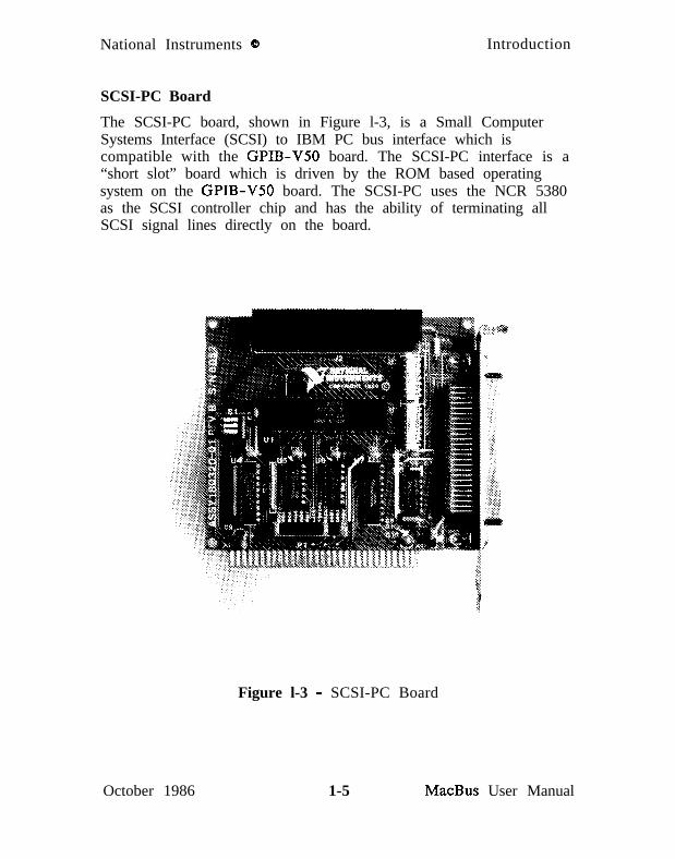
SCSI-PC Board
The SCSI-PC board, shown in Figure l-3, is a Small ComputerSystems Interface (SCSI) to IBM PC bus interface which iscompatible with the GPIB-V50 board. The SCSI-PC interface is a“short slot” board which is driven by the ROM based operatingsystem on the GPIB-V50 board. The SCSI-PC uses the NCR 5380as the SCSI controller chip and has the ability of terminating allSCSI signal lines directly on the board.
October 1986
Figure l-3 - SCSI-PC Board
1-5 MacBus User Manual

Introduction (3 National Instruments
EQUIPMENT SUPF’IJED
Table l-l lists the equipment supplied in the National InstrumentsMacBus Kit. Optional equipment is listed in Table l-2.
TABLE l-l - Equipment Supplied in the MacBus Kit
Description Part NumberMacBus Hardware Unit (115V)
with 128K bytes RAM 776139-01 *with 512K bytes RAM 776 139-02 *
MacBus Hardware Unit (230V)with 128K bytes RAM 776139-03 *with 512K bytes RAM 776139-04 *
* Includes:- Chassis with power supply and power cord- GPIB-V50 microprocessor board with GPIB interface- SCSI-PC interface board- Distribution disk with IBDIAG, IBCL Window, IBCLload,
SCSI_CONF, and gpib.com files **- MacBus User Manual
** For a description of the tiles included on the distribution disk,refer to MACBUS HARDWARE DISTRIBUTION DISKparagraph in this section.
MacBus User Manual l - 6 October 1986

National Instruments &3 Introduction
TABLE l-2 - Accessory Equipment for MacBus Kit
Description Part NumberMacBus RAM Memory Field Upgrade Kit 776139-03
(128K to 512K)MacBus Software 776140-01
Includes:- Distribution disk with IBIC, IBCONF, and
Microsoft BASIC language interface *- Software Reference ManualLabVIEW Software (double sided floppies) 776141-01SCSI Cable (External)
Macintosh Plus to MacBus 180323-01MacBus to SCSI peripheral 180330-01
SCSI Extension Cable (Internal) 180329-01Megamax C Language Interface 776140-02
(includes Manual, requires MacBus softwarepackage)
MacBus Technical Reference Manual 1 320075-01
* For a description of the files included on the distribution disk,refer to MACBUS SOFTWARE DISTRIBUTION DISKparagraph in this section.
February 1987 l -7 MacBus User Manual

Introduction 8 National Instruments
h4ACBUS HARDWARE DISTRIBUTION DISK
The following files are included with your MacBus hardware uniton your distribution disk.
. IBDIAG
. IBCL Window
l IBCLload
. SCSI_CONF
l gpib.com
Refer to the following paragraphs for a description of each file.
IBDIAG
IBDIAG is a utility which provides the results of the onboarddiagnostics run on MacBus at power-on. There are five diagnostictests which are run. They are:
1. RAM test
2. ROM test
3. Non-interfering GPIB test
4. CPU test of internal registers
5. CPU test of onboard peripherals
MacBus User Manual l -8 February 1987

National Instruments 0 Introduction
The IBDIAG utility displays the results of these diagnostics. Azero indicates no error. The remaining error codes are defined asfollows:
Error Code 1 Description
0 1 No errors1 ROM checksum failure2 CPU internal register failure3 1 CPU onboard peripheral failure 14 1 RAM failure I5 GPIB failure6 SCSI bus error
Refer to SECTION FIVE of this manual for troubleshooting theabove errors.
Run IBDIAG by double-clicking the IBDIAG icon (shown below).
r;;;fiIBDIAG
IBCL Window
The IBCL Window utility allows interactive communication withthe IBCL operating system on MacBus. IBCL commands areentered directly to the IBCL interpreter on MacBus. Any outputor error messages generated are displayed on the Macintosh screen.
Run IBCL Window
The IBCL Window program is provided as an executable file onyour distribution disk.
February 1987 l - 9 MacBus User Manual

Introduction 8 National Instruments
To run IBCL Window, insert the distribution disk into the diskdrive and double-click the disk icon displaying the file icons.Now double-click the IBCL Window icon (shown below).
IBCL Window
You will see the IBCL prompt ok appear onsee:
your screen. If you
Error : ECOMMReset MacBus and Try Again ?
reset your MacBus by turning the power off and back on again.
Wait at least 10 seconds for the power-up diagnostics to completeand type ‘y’ <cr>. You will then see the IBCL prompt ok.
Exit IBCL Window
To exit the IBCL Window type stop. This will return you to theMacintosh Plus Finder.
IBCLload
The IBCL utility, IBCLload, allows files containing IBCLcommands to be sent directly to the IBCL interpreter on MacBus.
With IBCLload, you can send your IBCL programs to MacBus andthen open the IBCL interactive window for direct access to theresources of MacBus.
MacBus User Manual l-10 February 1987

National Instruments @ Introduction
Run IBCLload
The IBCLload program is provided as an executable file on yourdistribution disk.
To run IBCLload, insert the distribution disk into the disk driveand double-click the disk icon displaying the file icons (shownbelow).
Now double-click the IBCLload icon (shown below).
The following screen will appear on your Macintosh screen:
!National InstrumentsIBCL File Transfer Utility Rev A.1Copyright (C) 1986 National Instruments, Inc.All rights reserved.
Type ‘help’ for help.Type ‘quit’ or ‘exit’ to exit program
There are six commands in the IBCLload utility. They are:
February 1987 l-11 MacBus User Manual

Introduction @ National Instruments
load <filename>:type <filename>:‘cm& c:
Send IBCL command tile to MacBusDisplay Iile to screenStop displaying file to screen or breakfrom ‘hung’ bus.
ibcl:stop:‘q’ or ‘e’:
Enter IBCL interactive windowReturn from IBCL interactive windowExit IBCLload utility
Any IBCL error generated by your source tile will be displayed onyour screen.
Any IBCL source file can also be downloaded from a BASIC or Cprogram. The function format is:
ibclload(filename)char *filename;
Any IBCL errors generated are written to the file IBCL.OUT.The editor can open this file for viewing. You must enter theeditor first and then open the file. Your BASIC or C programcontaining the ibclload call must be linked to CIB.0 contained onyour distribution disk.
SCSI_CONF
The utility SCSI_CONF allows the SCSI ID of MacBus to bechanged from its default setting of 6.
The Macintosh Plus has a fixed SCSI ID of 7. Valid SCSI IDS forthe remaining devices are 0 to 6. MacBus has three hardwareswitches located on the SCSI interface board (see the MacBus UserManual for more information). These switches must be configuredso that they are consistent with the software setting in this field.The factory default setting is SCSI ID = 6.
The current SCSI ID is maintained in the file gpib.com. This tileis provided on the distribution disk.
If you are operating under the Macintosh hierarchical file system,the file gpib.com must reside in one of three locations for
MacBus User Manual 1-12 February 1987

National Instruments Q Introduction
SCSI_CONF and other MacBus utilities to have access to it.
The directory (or folder) where the application SCSI_CONFand/or other MacBus utilities reside.
The system folder.
The root directory (or folder).
The file must be named gpib.com.
When executed, SCSI_CONF first looks for the gpib.com file inthe above mentioned locations. If SCSI CONF cannot findgpib.com, you will be prompted to choose to have it created withfactory ID setting of 6. The file will be placed in the systemfolder.
Run SCSI_CONF
The SCSI_CONF program is provided as an executable file on youdistribution disk.
To run SCSI_CONF, insert the distribution disk into the diskdrive and double-click the disk icon displaying the file icons.Now double-click the SCSI_CONF icon.
A help screen will appear on your Macintosh Plus screen. Thecurrent SCSI ID setting is displayed. Enter the new SCSI ID bytyping a number from zero to six. SCSI_CONF will verify yourentry by re-displaying to the screen.
Exit SCSI_CONF
Exit SCSI_CONF by typing ‘e’ or ‘q’. The new SCSI ID is savedto the file gpib.com where other MacBus applications have accessto it.
February 1987 l-13 MacBus User Manual

Introduction 0 National Instruments
gpib.com
The file gpib.com contains the current SCSI ID information. Itmust reside in one of three locations (see SCSI_CONF paragraphabove for details).
IBCL SOURCE FILES
The remaining files on the distribution disk contain IBCL sourcecode. These files are:
l Scaler
l MicroASM
. HiFlow
. 721911BCL
. 72191ASM
. String
. Forth83
. Toolbox
0 case
. BCD
l Upper Case IBCL
To use these files you must first download them to the IBCLinterpreter. There are two methods of doing this. The firstmethod uses the IBCLload utility. This utility was described in theIBCLload paragraph mentioned earlier. The second methoddownloads an IBCL source file to MacBus through functions orsubroutines in a language interface library. This method may onlybe used if you have purchased a MacBus language interfacelibrary from National Instruments. Consult the appropriatelanguage interface supplement for details.
MacBus User Manual l-14 February 1987

National Instruments @ Introduction
Scaler
This tile contains IBCL source code allowing manipulation ofsoftware floating point numbers. The IBCL words defined inScaler are documented in APPENDIX E - SCALED NUMBERS.
MicroASM
This file contains IBCL source code allowing you to use INTEL8086/88 sytle assembly language mnemonics to create very fastIBCL words. For more details see SECTION THREE - USINGASSEMBLY LANGUAGE FROM IBCL.
HiFlow
This file contains IBCL source code allowing you to use high-levelcontrol flow constructs such as begin...again,begin...while...repeat, etc. These IBCL words are documented inSECTION THREE - Conditional Execution & Loops.
721911BCL and 72191ASM
These files contain IBCL source code allowing manipulation of theNEC 72191 floating point coprocessor. 721911BCL containshigh-level IBCL definitions and may be downloaded at any time.72191ASM contains assembler extensions allowing you to use72191 opt codes in IBCL assembly language definitions. You mustdownload the assembler utility MicroASM before you download72191ASM. The definitions contained in these two files aredocumented in SECTION THREE - NEC 72191 Architecture.
String
This file contains IBCL source code allowing convenientmanipulation of ASCII strings. The IBCL words are documentedin SECTION THREE - String Functions.
February 1987 1-15 MacBus User Manual

Introduction 0 National Instruments
Forth83
As shipped by National Instruments, IBCL closely approximates aFORTH79 standard system. Forth83 contains IBCL source codethat will bring IBCL into compatibility with the Forth83 standard.These words are not documented in this manual; consult anyForth-83 reference for their usage.
Toolbox
This file contains IBCL source code which supports IBCLdebugging.
case
This executable file converts the contents of your text file fromuppercase to lowercase to allow your file to run with IBCL.
BCD
This file contains IBCL source code providing IBCL support forBinary Coded Decimal numbers.
Upper Case IBCL
This file contains IBCL source code which will convert the wordsin the IBCL dictionary from lowercase ot uppercase.
MacBus User Manual 1-16 February 1987

National Instruments @ Introduction
MACBUS SOFTWARJZ DIS~UTION DISK
The two tiles included on your software distribution disk are:
. IBIC
. IBCONF
Refer to the following paragraphs for a description of each file.
IBIC
The IEEE-488 Bus Interactive Control utility (IBIC) allowscommands contained in the C Language and BASIC Languageslibraries to be run interactively from a terminal.
Start IBIC by double-clicking the IBIC icon (shown below).
IBCONF
The IEEE-488 Bus Configuration utility (IBCONF) is a screen-oriented, interactive program. IBCONF is used to edit thecharacteristics of the board and devices in the system. You mustrun IBCONF to change the MacBus SCSI ID if it is different fromthe factory setting of 6.
Start IBCONF by double-clicking the IBCONF icon (shownbelow).
IBCONF
February 1987 1-17 MacBus User Manual

National Instruments @
SECTION TWO - INSTALLATION
Installation
INSPECTION
Before you install MacBus, inspect the shipping container and itscontents for damage. If damage appears to have been caused inshipment, tile a claim with the carrier. Retain the packagingmaterial for possible inspection or for reshipment.
If the equipment appears to be damaged, do not attempt tooperate it. Contact National Instruments for instructions.
INSTALLATION
There are five basic steps to installing MacBus.
1. Verify voltage requirements.
2. Install optional internal adapters.
3. Connect cables.
4. Turn power switch to on.
5. Run the diagnostic software.
Verify Voltage Requirements
MacBus is shipped from the factory set at a particular operatingvoltage, either 115 VAC or 230 VAC, and cannot be changed bythe user.
Verify that the voltage you are using is the same as the voltage onthe label on the back of the MacBus chassis. If it is not, contactNational Instruments for further instructions.
Install Internal Options
The basic MacBus computer consists of a system unit with 2 cards,a GPIB-V50 microprocessor card and a SCSI-PC interface card for
October 1986 2- l MacBus User Manual

Installation 0 National Instruments
connection to the Macintosh Plus. You may add compatibleoptions to expand your system to meet your particular needs.
NOTE
Before attempting to install an option on MacBus,check with National Instruments to verify that theoption is supported on MacBus. Use of othermanufacturers cards are the sole responsibility ofthe customer.
If you do not need to install internal options, you may skipdirectly to the paragraph Connect Cables. The steps for installingoptional cards are listed below.
1.
2.
3.
4.
5.
6.
Turn the system unit’s power switch to the OFF position.
Remove any externally attached devices from the MacBusback panel.
Unplug your system unit’s power cord from the wall outlet,and also from the back of MacBus.
Remove the four cover mounting screws located in eachcorner of the rear panel.
Remove the cover by sliding it towards the front of themachine in a straight line.
Some optional cards can be damaged by static electricitycaused by handling of the cards. Make sure you take thefollowing precautions when installing optional cards.
a. Use a grounded wrist-strap and work on a groundedwork area.
b. Remove the optional cards from their shippingcontainers carefully and hold the adapters by theiredges only.
c. Avoid touching any connections or components on theoptional adapters or on any card already installed in theunit.
MacBus User Manual 2-2 October 1986

National Instruments 0 Installation
7.
8.
9.
10.
d. When installing options, hold the adapter by their uppercorners or top edges only.
Remove the screw that holds the expansion slot’s cover inplace, then remove the cover.
Firmly press the adapter into the expansion slot and reinstallthe screw removed in Step 7. The I/O connectors on themotherboard are slot independent, that is, any adapter can beinstalled in any available slot.
When adding optional interface adapters, it may be necessaryto change such parameters as I/O addresses, interrupt levels,or DMA channels, if they conflict with those of the SCSI-PCcard. It may also be necessary to change the SCSI ID or toremove the power resistors in your system. To determine ifthese steps are necessary see SECTION FOUR -TECHNICAL INFORMATION.
Install the system unit’s cover and reinstall the four covermounting screws removed in Step 4.
October 1986 2-3 MacBus User Manual
Installation 0 National Instruments
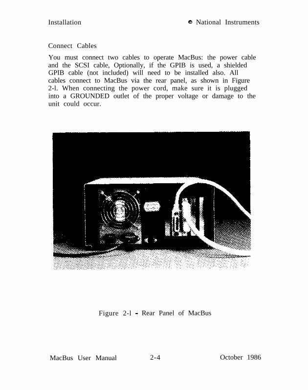
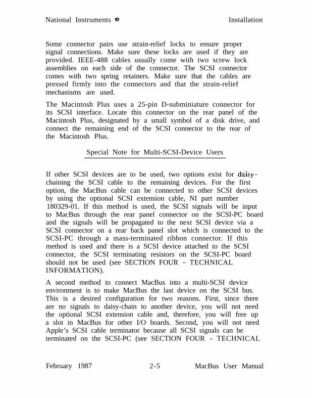
Connect Cables
You must connect two cables to operate MacBus: the power cableand the SCSI cable, Optionally, if the GPIB is used, a shieldedGPIB cable (not included) will need to be installed also. Allcables connect to MacBus via the rear panel, as shown in Figure2-l. When connecting the power cord, make sure it is pluggedinto a GROUNDED outlet of the proper voltage or damage to theunit could occur.
Figure 2-l - Rear Panel of MacBus
MacBus User Manual 2-4 October 1986
National Instruments 8 Installation
Some connector pairs use strain-relief locks to ensure propersignal connections. Make sure these locks are used if they areprovided. IEEE-488 cables usually come with two screw lockassemblies on each side of the connector. The SCSI connectorcomes with two spring retainers. Make sure that the cables arepressed firmly into the connectors and that the strain-reliefmechanisms are used.
The Macintosh Plus uses a 25-pin D-subminiature connector forits SCSI interface. Locate this connector on the rear panel of theMacintosh Plus, designated by a small symbol of a disk drive, andconnect the remaining end of the SCSI connector to the rear ofthe Macintosh Plus.
Special Note for Multi-SCSI-Device Users
If other SCSI devices are to be used, two options exist for daisy-chaining the SCSI cable to the remaining devices. For the firstoption, the MacBus cable can be connected to other SCSI devicesby using the optional SCSI extension cable, NI part number180329-01. If this method is used, the SCSI signals will be inputto MacBus through the rear panel connector on the SCSI-PC boardand the signals will be propagated to the next SCSI device via aSCSI connector on a rear back panel slot which is connected to theSCSI-PC through a mass-terminated ribbon connector. If thismethod is used and there is a SCSI device attached to the SCSIconnector, the SCSI terminating resistors on the SCSI-PC boardshould not be used (see SECTION FOUR - TECHNICALINFORMATION).
A second method to connect MacBus into a multi-SCSI deviceenvironment is to make MacBus the last device on the SCSI bus.This is a desired configuration for two reasons. First, since thereare no signals to daisy-chain to another device, you will not needthe optional SCSI extension cable and, therefore, you will free upa slot in MacBus for other I/O boards. Second, you will not needApple’s SCSI cable terminator because all SCSI signals can beterminated on the SCSI-PC (see SECTION FOUR - TECHNICAL
February 1987 2-5 MacBus User Manual

Installation 0 National Instruments
INFORMATION).
Another important consideration for multiple SCSI device users isto make sure that no two SCSI devices have the same SCSI ID.The SCSI-PC is shipped from the factory with its SCSI ID set to6. If this conflicts with another SCSI ID, one of the devices’ IDSwill need to be changed. To change the SCSI ID on the SCSI-PCrefer to SECTION FOUR - TECHNICAL INFORMATION.
Turn Power Switch to ON
The next step to setting up MacBus is turning the unit’s powerswitch to ON. Wait 10 seconds before appling power to theMacintosh Plus so that MacBus has time to complete its power-onself-test. If changes have been made to certain adapters, such aschanging the SCSI ID on the SCSI-PC, they will take effect whenthe MacBus unit is powered on.
Run the Diagnostic Software
The last step to setting up MacBus is to run the diagnosticsoftware to verify the system was set up correctly. The diagnossoftware is included on the distribution disk which came withyour MacBus Kit. It can be run by double-clicking on theIBDIAG icon. If the system was installed correctly, the diagnossoftware will print “Diagnostic Completed Successfully” on theMacintosh Plus screen. If any other result is posted, refer toSECTION FIVE - DIAGNOSTICS AND TROUBLESHOOTING
tic
tic
MacBus User Manual 2-6 February 1987

SECTION THREE - IBCL
INTRODUCTION
IBCL (Interface Bus Control Language)programming language used to programa pair of EPROM memory chips on theboots automatically when you power onsequence is necessary.
is a powerful interactiveMacBus. IBCL resides inGPIB-VSO board. IBCLMacBus; no initialization
IBCL is a stack-based language that can be tailored to specificapplications by the addition of new commands. Users who arefamiliar with the Forth programming language will recognizemany similarities.
This section describes existing IBCL commands and techniques foradding new ones to the system. For tutorial-style information,consult one of the Forth language books listed below:
Forth, An Applications Approach by David L. Toppen, McGraw-Hill.Forth Programming by Leo J. Scanlon, Howard W. Sams Publications.Mastering Forth by Anita Anderson & Martin Tracy, Prentice Hall.Starting Forth by Leo Brodie, Prentice Hall.Thinking Forth by Leo Brodie, Prentice Hall (Advanced Techniques).
LANGUAGE STR.UCTUl3.E
An IBCL program is a list of numbers or one-word commands. Aword is an unbroken string composed of up to 63 characters. TheIBCL standard word set includes the following characters:
!“#$%&‘(I*+,-./ 0123456789:;<=>?@abcdefghijklmno pqrstuvwxyzC 1
IBCL will define and recognize words composed of any sequenceof &bit bytes. Space, carriage return, and linefeed serve as worddelimiters. Also some ASCII codes may have a special meaning to
October 1986 3- l MacBus User Manual

IBCL Q National Instruments
your system. It is usually best to limit yourself to the standardcharacter set, but you may use uppercase and the special graphicscharacters if you wish.
Learning IBCL is similar to adding a few hundred words to yourvocabulary. The names of the words will often relate to Englishwords that you already know. The definitions of these words aredetailed and specific; they are neither ambiguous nor dependenton context, and can be learned a few at a time.
The definition of a new IBCL word is a list of previously definedIBCL words or a machine code primitive.
An IBCL program is executed by executing a sequence of words.If a word in the sequence is defined by a code primitive, thatcode is executed. When a word is defined by a list of other IBCLwords, execution of the original list is suspended until the listfrom the definition is executed. When you run an IBCL program,each word in the sequence composing the program executes inturn.
This execution sequence is different from subroutine orientedlanguages. In a subroutine oriented language, you may still definea higher level subroutine as a list of lower level ones, but time isalways wasted by returning to the high-level routine beforeproceeding to the next routine in the definition. The moreefficient course is apparent:
MacBus User Manual 3-2 October 1986

o National Instruments IBCL
subroutine compiler IBCL
S
” >>>>>>>>
b subroutine br <<<<<<-z-z0
IJ > > > > > > > >
t subroutine ci <<-z-z-c<<<ne >>>>>s>>
/ subroutine d* <<<<<<<<
I >>>>>>>>
B IBCL-word-bC V
L V
V
W IBCL-word-c0 V
:
V
V
IBCL-word-de <<<<<<<<
Stacks
IBCL keeps the data it is using on a stack. IBCL words generallytake their input parameters from this stack and leave their resultson it. The most fundamental IBCL words are defined in machinecode and perform the following functions.
Place an address on the stack.Replace an address on the stack with the contents of thataddress.Replace the top element(s) on the stack with the result ofsome math or logic operation using them.Place a copy of some stack element on top of the stack.Rearrange the top few elements of the stack.Delete element(s) from the top of the stack.
A stack may be viewed as a deck of cards lying face up with eachcard only partially covering the one below, as in some solitairegames. In this game, you have the ability to create a copy of anycard you see in the deck and place it on top of the stack. Youcan also remove any card and place it on top, but this takes muchlonger. The top three cards are most easily copied or rearranged.A math or logic operator like max (maximum value) would takethe top two cards from the stack, place the higher valued oneback, and destroy the other. Instead of playing cards, we couldhave a stack of plain cards with numbers written on them and a
October 1986 3-3 MacBus User Manual

IBCL o National Instruments
supply of blank cards. Addition is defined as removing the toptwo cards, writing the sum of their numbers on a blank card, andplacing the new card on the stack.
IBCL has another stack which usually takes care of itself. It iscalled the return stack. When a higher level word is executed,each lower level word in its definition is executed. But each ofthese words may also be defined in terms of yet lower level words,until the lowest level words defined in machine code are reached.As IBCL descends through each level of a definition, it leaves theaddress of the next word of the current level on the return stack.When the lower level is completed, this address is removed fromthe return stack and execution proceeds from that point.
Sometimes it is convenient to temporarily move some word fromthe data stack to the return stack, usually to perform someoperation using words lower on the data stack. Because of thedefinition interpreter’s use of the return stack, that word shouldonly be used in the definition placing it on the return stack. Itmust be removed from the return stack before execution of thedefinition terminates.
Dictionary
IBCL ‘remembers’ word definitions using a data structure calledthe dictionary. When you define a new word, IBCL adds adictionary entry for that word. The only words IBCL understandswhich are not in the dictionary are numbers.
IBCL separates the dictionary entry for each word into three partsin three different segments (a segment is a contiguous block ofMacBus memory). The word’s ASCII name string is stored in avocabulary segment. Its definition is stored in the definition listsegment. The first byte-pair of the list contains the address in thecode segment of the code primitive that begins execution of theword. (To avoid confusion with IBCL “words”, byte-pair will beused instead of word when referring to a 16-bit memory location.)
Since each aspect of the definition naturally defaults to its ownsegment register, the partition generates no memory or time
MacBus User Manual 3-4 October 1986

o National Instruments IBCL
overhead loss. In addition, no more memory pointers are neededthan in a conventional Forth system. The pointer into thedefinition list segment replaces the pointer to the previous wordfound in conventional systems. The pointer to the previous wordis not needed since only word names occupy the vocabularysegments and since each vocabulary has its own segment.
Vocabularies
The vocabulary entry has three parts. The first byte-pair containsthe address in the definition list segment of the beginning of theword’s definition. The following bytes contain the ASCII namestring. The last byte contains the number of bytes needed for thestring. Its high-order bit is set to make it easier to find duringthe forward searches required by decompilers. The second tohigh-order bit is set if the word is defined as immediate. When aword is encountered in a definition, the address of its definitionlist (from the first byte-pair of the vocabulary entry) is usuallyentered into the new definition. If the word is immediate, it isexecuted instead.
IBCL allows many separate vocabularies. This allows you toseparate definitions into well-organized groups, much like youwould place related C functions in a single file. IBCL can findwords faster when it only has to search a couple of vocabulariesinstead of the entire dictionary. IBCL provides a separate segmentfor each vocabulary defined.
The two vocabularies, ‘context’ and ‘current’, are always singledout for special treatment. The ‘context’ vocabulary is searchedfirst for words encountered in the input stream. If the word isnot found, the root directory (named IBCL) is searched. The‘current’ vocabulary is the vocabulary to which new definitions areadded. The variables ‘context’ and ‘current’ contain pointers tothese two vocabularies.
October 1986 3-5 MacBus User Manual

IBCL o National Instruments
Definitions
The actual definition of an IBCL word consists of two parts: thecode field and the parameter field. The code field is a singlebyte-pair designating the address in the code segment of themachine code primitive associated with the word. The parameterfield immediately follows the code field. Its use varies from wordto word; a pointer to the parameter field is passed to the machinecode primitive, which may use the parameter field in any way itchooses.
The simplest IBCL words are written in machine code. Thesewords have no parameter field. IBCL executes the code addressedby the pointer stored in the parameter field. These words executevery fast.
High level definitions are more complicated. The parameter fieldof a high-level definition contains a list of addresses. Eachaddress points to the code field of one of the lower level wordsmaking up the high-level word. The code field of a high-levelword points to code that saves IBCL’s ‘program counter’ on thereturn stack and replaces its value with the address of the high-level word’s parameter field (remember, the parameter fieldaddress is made available to the machine code primitive for anypurpose; in this case it contains the list of addresses composing theword’s definition.).
The last address in the list making up a high-level definition willpoint to the code field of a word that removes the address fromthe return stack and restores IBCL’s ‘program counter’ to thisvalue, thus returning control to the next level up.
Other commonly used IBCL word types are constants andvariables. The code field of a constant points to a routine thatplaces the contents of the first byte-pair of the parameter field onIBCL’s data stack. The code field of a variable points to a routinethat places the address of the first byte-pair of the parameter fieldon the data stack.
MacBus User Manual 3-6 October 1986

o National Instruments IBCL
Postfix Notation
IBCL uses postfix notation syntax. In postfix, one writes the stacknumbers and then the operators. Numbers are pushed onto a stackand taken from it. For instance:
7 212 3 / * -
First 7, and then 2, 12, and 3 are pushed onto the stack. Then 12is divided by 3 and the result is placed on the stack. Now wehave 7, 2 and 4 on the stack and the next operator is *, leaving 7and 8 on the stack. The - leaves -1 on the stack.
Note that it is not the syntax of IBCL that gives rise to thisappearance of postfix notation, but the semantics of those wordsused to implement mathematical operations most efficiently. Otherforms of notation can be developed on this system if desired.
Command Line Input
IBCL executes the word query when it has exhausted its ASCIIinput and needs some more. This word sets status that allows theMacBus’ host system to learn of the situation and download newinput. The exact method used by the host to accomplish thisvaries depending on the host software package you have; seeSECTION ONE - IBCL Source Files for details.
October 1986 3-7 MacBus User Manual

IBCL o National Instruments
THE IBCL INTERPRETERS
IBCL has two interpreters, the inner interpreter and the outerinterpreter. The inner interpreter does nothing except branchfrom one machine code routine to the next. The nesting andunnesting routines supporting high-level IBCL definitions areamong the code routines through which execution passes.
The outer interpreter accepts text from the host. It then attemptsto parse the text string as a sequence of IBCL words and/ornumbers. In execute mode, words are executed and numbers areplaced on the stack. In compile mode, words and numbers areentered into the definition of the new word.
Inner Interpreter Sequence
IBCL uses the si register as its ‘program counter’. si always pointsto the next entry in a word’s definition list to be executed.IBCL’s inner interpreter is the simple four-byte machine codesequence:
lodsw ;move code field address of next word;into ax register
xchg di, ax ;move next word cfa into dijmp [dil ;execute code pointed to by cfa
Note that [di+2] will contain the address of the parameter field,which the code executed may use in any way it chooses.
If the definition list which the inner interpreter is interpretingconsists of a list of pointers to simple machine code primitiveinstructions such as stack and math words, execution will simplyproceed from one word to the next in the list. A few specialmachine code primitives alter this orderly flow.
One of these diverting primitives is <docob. <docob is theprimitive that nests control to a lower level definition as discussedearlier.
MacBus User Manual 3-8 October 1986

Q National Instruments IBCL
exit is the last pointer in a definition list. Its machine codeprimitive pops the top element from the return stack andcontinues list interpretation at that address. This is the word fromwhich control was originally diverted.
There are several other words which alter the sequentialinterpretation of a definition list. x.5 and <abort”> are compiledby the immediate words, .” and abort”. They control display ofthe following inline string and cause interpretation to skip to theword following that string. lit and dlit cause the following wordor double word value to be pushed onto the stack; interpretationcontinues after the last value.
execute causes a branch to the word pointed at by the top valueon the stack, just as if the pointer to that words code field addresshad been in the list instead of execute.
The remaining control-flow altering words handle the high-levelflow control within a single definition list. branch causes controlto skip forward or backward the number of words contained inthe following location. Obranch does so only if the top word onthe data stack is zero. Otherwise control continues with the wordfollowing the unneeded relative offset.
The do loop terminating words are similar in function andappearance to Obranch. First they perform the additional task ofupdating an index and comparing it to a limit. If the limit hasexceeded bounds, control is transferred as with branch. If thebound has not been exceeded interpretation continues after therelative offset.
Outer Interpreter Sequence
Text is accepted a line at a time from the host. A line can be upto 1024 bytes long. The interpreter further breaks each line orblock into individual words and processes them one at a time insequence. A word is a string of characters preceded and followedby blank spaces or by a null. A few words require text strings asfollowing arguments and use a special delimiter such as quote toend the string. Within these strings, blanks are not interpreted as
October 1986 3-9 MacBus User Manual

IBCL o National Instruments
word separators. These strings are processed by the precedingword rather than by the interpreter.
One such special string is the comment which opens with ( . Theinterpreter ignores input after the ( word until the next ) or untilthe end of the current line or block. The initial ( is a true IBCLword but the closing ) is only a delimiter and need not bepreceded by a blank.
Once a word is extracted, an attempt is made to locate it in thedictionary. If it is found, its code field address is returned. Inexecution mode the definition beginning at this address isexecuted, but when compiling a higher level word the address isappended to the definition being created unless it is an‘immediate’ word. These execute even within a colon definition.
The IBCL word immediate makes the most recently compiledword immediate.
If the word was not located, the interpreter assumes that it is anumber and attempts to convert it to binary form. The valuestored in base identifies the current number system(ten,decimal;eight,octal;sixteen,hexadecimal). The number maybegin with a minus sign. If it contains a decimal point, it isconverted as a double length number, otherwise it must fit in asingle byte-pair. When a single byte-pair number is too large,high-order bits are lost. A single byte-pair number may be assmall as -32768 or as large as 65535, a double byte-pair numbermay be as small as -2147483648 or as large as 4294967295. Theupper half of the positive range is for unsigned numbers only.Double byte-pair numbers cannot overflow, but the correctdecimal point location must be determined from the user variabledpl.
The decimal point in the double numbers identifies them as doublenumbers but does not affect the binary value generated. The twonumbers 123. and 1.23 produce the same binary value. Thelocation of the decimal point is available in the user variable dpl,which is 0 and 2 for the above numbers. dpl is used by theapplication to scale numbers according to the location of the
MacBus User Manual 3-10 October 1986

o National Instruments IBCL
decimal point.
In execution mode, the binary value is placed on the stack. Forsingle byte-pair numbers in compilation mode, the code fieldaddress of lit (literal) is appended to the definition followed bythe binary value. For double byte-pair numbers in compilationmode, the code field address of dlit (double literal) is appended tothe definition followed by the low-order byte-pair of the doublenumber and then the high-order byte-pair.
If the string cannot be converted, the interpreter aborts with anerror message. The stacks are cleared and the rest of the block orline being interpreted is ignored.
The interpreter uses -find (see DEFINING NEW WORDSparagraph) to locate the potential word in the dictionary. Sincethe source string for -find is the next word in the input stream,this also advances the interpreter over the input text.
If the string is not a word, number is used to convert it to binaryform. number is vectored through ‘number to <number> so youmay change the operation of number by storing the code fieldaddress of your numeric conversion routine in ‘number.<number> expects the address of the source string’s count byte onthe stack. It replaces the address with the double word binaryvalue converted using the current base. If conversion is notpossible, <number> aborts with a “NOT RECOGNIZED” error.The user variable dpl will contain 8000H if no decimal point waspresent in the numeric string. In this case the number was singleword length and the top word on the stack may be dropped.Other values in dpl represent the power of 10 by which the doubleword integer returned must be multiplied in order to recover theoriginal decimal value. The interpreter ignores dpl except as aflag to drop the top word of single word entries.
When all words in the input stream have been executed, query isused to obtain more input and the entire cycle repeats.
October 1986 3-11 MacBus User Manual

IBCL o National Instruments
Errors
When an error is encountered during interpretation, an errormessage is usually generated using abort”. Execution of the runtime portion of this word, <abort”>, clears the stacks and prints anerror message. Control is then returned to the terminal to awaitthe next line of input. See DEFINING NEW WORDS, COLONDEFINITIONS, and IBCL INPUT paragraphs.
abort is vectored through ‘abort to <abort>. You may alter theoperation of abort by storing the code field address of your abortword in the variable ‘abort. It generates no error messages butdoes clear the stack, resets both context and current vocabulariesto IBCL, and returns control to the terminal.
Storing 0 in the user variable warning will suppress non-fatalsystem error messages. The only non-fatal error in the basesystem is the “ISN’T UNIQUE” message generated for attempts toredefine a word that is already in the current vocabulary or in theIBCL vocabulary. The word will be redefined, and access to theold definition is lost. Previously defined words that used the olddefinition are not affected.
MacBus User Manual 3-12 February 1987

Q National Instruments IBCL
STACK MANIPULATION
IBCL uses two stacks: the parameter or data stack and the returnstack. The parameter or data stack is used to pass informationfrom one word to the next. It is often referred to as “the stack”.The return stack is used by the interpreter to find its way back upthrough nested sequences of words being executed. It is alwayscalled “the return stack”. Occasionally the return stack is usedwithin a word as temporary storage. Any temporary items on thereturn stack must be removed before the word completesexecution. The return stack also holds the index and limit for doloops within colon definition words. These are automaticallyremoved when the loop terminates.
Parameter stack words rearrange, drop, and duplicate words on theparameter stack. Note that “words on the parameter stack” referto 16-bit numbers, not to IBCL definitions.
The parameter stack grows downward from an offset within thestack segment. The parameter stack pointer occupies the spregister. The return stack grows upward from the bottom of thestack segment. The return stack stack pointer occupies the bpregister. Both reside in the stack segment and use the stacksegment register.
Any words which refer to the state of the stack refer to the statethat existed before the word was executed.
October 1986 3-13 MacBus User Manual

IBCL o National Instruments
Parameter Stack
?dupdepthdropdupovern pick
n roll
rotswapSP@
sp!SPO
so
ddrop
Duplicate top word on stack if it is non-zero.Return number of words on stack before operation.Drop top word from stack.Duplicate top word on stack.Duplicate second from top word on stack.Duplicate n’th word on stack.1 pick is equivalent to dup2 pick is equivalent to overRemove n’th word from stack, leaving it on top.2 roll is equivalent to swap3 roll is equivalent to rotThis is a time consuming operation since all wordson stack from top through n’th must be moved.Remove third word from stack, leaving it on top.Remove second word from stack, leaving it on top.Return offset into stack segment of top of stack.(Top of stack has the lowest physical address.)(Return stack pointer, stored in the sp register)Initialize stack pointer to SO, clearing stack.Return the address within the stack segmentdescriptor pointing to the bottom of the stack.Return the address of the bottom of the stack.When the stack pointer has this value,the stack is empty.Drop the top two words from the stack.Duplicate the top pair of words on the stack.Produces same result as over over.
The following external words are from the Forth 79 & 83Standard double number word set, with the prefix characterchanged from 2 to d. They correspond to their single wordcounterparts, but operate on pairs of words.
MacBus User Manual 3-14 October 1986

Q National Instruments IBCL
High level implementation.
: dover 4 pick 4 pick ;: drot 6 roll 6 roll ;: dswap 4 roll 4 roll ;
Code level implementation (see USING ASSEMBLY LANGUAGEFROM IBCL paragraph).
code dover
code drot
code dswapcx push. bx push.
Return Stack
>r+>I-
dup>rrdropr@r>rp@rp!
bx push. bp sp xchg.bx 4 +Ibpl mov. ax 6 +Cbpl mov. sp bp xchg.ax push. end- code2 +cbp1 pop.dx POP. cx POP-ax POP. di pop.cx push. dx push.2 +Cbpl push. bx push.di push. bx ax xchg. end-code
cx POP- ax POP. dx POP.dx push. bx ax xchg. end-code
Transfer top word from data stack to return stack.Add top word on data stack ontotop word of return stack.Copy top word from data stack to return stack.Drop top word from return stack.Copy top word from return stack to data stack.Transfer top word from return stack to data stack.Return value of return stack pointer (bp register).Clear the return stack.
October 1986 3-15 MacBus User Manual

IBCL Q National Instruments
ARITHMISTIC & L O G I C
The arithmetic and logic words Iind all of their inputs on the datastack, remove the inputs from the stack, and return their resultson the stack.
The ranges for the supported number types are:
integer type decimal range hexadecimal range- - - - - - - - - - - - - _ - - - - - - - - - ________------_-signed -32,768 32,767 -8000 7FFFunsigned 0 65,535 0 FFFFdouble -2,147,483,648 2,147,483,647 -8000.0000 7FFF.FFFFlogical 0 for false; -1 generated, non-zero accepted for true
Some people don’t like using -1 for true, they would rather use 1to be able to use it as a counter. Negative one can be used as acounter and the eventual sum negated with negligible time loss. Italso has compelling advantages, too numerous to cover completely.
Suppose we want to find the sum of a subset of a series ofnumbers. A parallel series contains true flags (-1) for thoseelements we want to include. The numbers are constants endingwith n, and the flags are variables ending with f.
an af @ and bnbf@and+ cncf@and+ e t c .
If truth had been 1 instead we could have resorted to a complexsequence of if statements within colon definitions or could haveused:
anaf@ * bn bf iii * + cn cf hl * + etc.
Of course, * requires five times the execution time that and uses.This type of summation is important in math, logic, electronics,and even games.
Error conditions other than divide overflow are not detected,although the flags from the operation can be returned on the stackby the flags> word. It should be used immediately after thearithmetic operator. Remember that for complex operators, the
MacBus User Manual 3-16 October 1986
Q National Instruments IBCL
flags are from the last operator invoked. The correspondingassembler operation (see USING ASSEMBLY LANGUAGEFROM IBCL paragraph) will indicate which flags are set. Errorsmay also be detected by checking whether the result has anobviously incorrect sign.
The divide error uses interrupt vector number zero. If you wishto replace this routine, the segment paragraph number atOOOO:OOOO and the offset at 0000:0002 must be set for your routine.The error will trap attempts to divide by zero and divisions thatproduce a quotient larger than the range for the divisor type.
When an arithmetic operation results in a number that is too large,positive or negative, the high-order bits are truncated. The resultreturned is usually very different from the desired result and oftendoesn’t even have the correct sign. Adding one to 32767 gives-32768.
Division follows the conventions of Forth-79. The remainder hasthe same sign as the dividend and the quotient is rounded towardzero. Note that this is the same type of division as performed bythe 8088 division instruction, making it the most efficient divisionfor this processor. The Forth-83 standard requires the remainderto have the same sign as the divisor and the quotient to berounded downward. The extra overhead to convert to this formshould be incurred only if it is genuinely essential. If theremainder will be used to round the quotient, the form isunimportant.
Constants
A few small integers are used so frequently that it is worthwhileto implement them as constants. When the interpreter encountersthem, they are located in the dictionary rather than being parsedby number. More important, when used in definitions, they resultin compilation of a single word rather than the lit and value pairof words produced by other integers. When executed, a constantpushes its value onto the top of the stack.
October 1986 3-17 MacBus User Manual

IBCL o National Instruments
The IBCL constants are: -2 -1 0 1 2 3 4
Unary Operators
These words alter the top word length integer on the stack. Mostoperate on either signed or unsigned integers. The few exceptions( 0-z O> abs neg b->w ) must obviously deal with signedquantities. The divide by 2 operator, 2/, also applies to signedquantities, since division requires the sign bit to propagatedownward as the number occupies fewer significant bits.
IBCL maintains the top word of the stack in the bx register, so nomemory accesses are required for these operators, not even a pushor pop. bx will be used as a shorthand notation for the top wordon the stack.
2- Subtract 2 from bx.
l- Subtract 1 from bx.
l+ Add 1 to bx.
2+2*2/
Add 2 to bx.Multiply bx by 2. (Shift bx left one bit.)Divide bx by 2. (Shift bx arithmetic right one bit,if bx is negative, increment by one.)
4+ Add 4 to bx.6+ Add 6 to bx.
o< If bx is less than 0, replace with -1, else with 0.o= If bx equals 0, replace with -1, else with 0.o> If bx is greater than 0, replace with -1, else with 0.
abs Replace bx with its absolute value.negate Replace bx with its 2’s complement (negate bx).
b->w Propagate the high-order bit of the low-order byte
MacBus User Manual 3-18 October 1986

o National Instruments IBCL
s->d
in bx through the upper byte (convert signed byteto signed word).Convert signed word length integer to signed doubleword integer. The former top word is pushed onedeeper into the stack. The new bx is all one bits ifthe old bx was negative, all zero bits otherwise.
The following unary operators replace the top twostack words. The high-order word is at the top ofthe stack in the bx register, the low-order word isbelow it.
dabsdnegate
Replace double word integer with its absolute value.Replace double word integer with its 2’s complement.
udsqrt Replace unsigned double word integer with unsignedsingleword square root.
Binary and Ternary Operators
Binary integer operators remove the top two words from the stackand replace them with the result of the operation, usually a singleword. Ternary integer operators remove the top three words fromthe stack and replace them with one or two results.
Mixed word length operators have one operand that is a doubleword. For double word length operators, both operands aredouble words. A double length word occupies two words on thestack. The high order half is toward the top of the stack with thelow-order half under it. Mixed operators generally begin with m ,double with d. To run some Forth-79 standard programs, it maybe necessary to redeline the d prefix words as 2 prefix words, orchange 2 prefix words in the program to d prefix words.
IBCL maintains the top word of the stack in the bx register andthe second stack word at the top of the physical stack. A singlepop is necessary to bring the second operand into the registers,assuring maximum efficiency. bx will be used as a shorthandnotation for the top word on the stack, and nx for the next word
October 1986 3-19 MacBus User Manual

IBCL o National Instruments
on the stack. The third word, when required, will be called t xand a fourth qx. Double length words require two of these codesseparated by a period.
All input words are removed from the stack and the resultbecomes the new bx. If more than one word is returned, a newnx is created as well.
Signed or Unsigned Operands
+ Add bx to nxSubtract bx from nx
= -1 if nx and bx were identical, 0 otherwise
d+d+-
Return sum of double integers bx.nx and tx.qxReturn nx.tx, negated if bx was negative.
Signed Operands
+- Return nx, negated if bx was negative.
* Multiply nx by bx.If product is too large, high-order bits are lost.
;mod
modl /
l /moD
Divide nx by bx, rounding quotient toward zero.Like / but the remainder is returned in nx withthe same sign as the dividend.Return the remainder of the division of nx by bx.Multiply nx by tx and divide the 32-bit productby bx, rounding toward zero. If result exceeds range(-32768 through 32767), a 0 divide error occurs.Like */ but the remainder is returned in nx withthe same sign as the intermediate product.
< -1 if nx is less than bx, 0 otherwise
MacBus User Manual 3-20 October 1986

o National Instruments IBCL
> -1 if nx is greater than bx, 0 otherwise
maxmin
Return the greater of nx and bx.Return the lesser of nx and bx.
Mixed Length Signed Operands
m+ Add double integer nx.tx to bx, return in bx.nx.m* Multiply bx by nx, return double integer bx.nx.m/ Divide double integer nx.tx by bx, rounding toward
zero. Return remainder in nx, quotient in bx.m*/ Multiply double integer tx.qx by nx and divide the
48-bit product by bx. Round double integerquotient bx.nx toward zero.
m/mod Like m/ but return double word quotient bx.nx andremainder tx.
d< bx becomes -1 if tx.qx is less then bx.nx,0 otherwise
Unsigned Operands
II*
u/mod
Multiply nx by bx, returning double word product.Low order word in nx, high-order word in bx.Divide double integer nx.tx by bx. Low order wordof dividend is tx, high-order word is nx. Returnremainder in nx, quotient in bx.
u< -1 if nx is below bx, 0 otherwiseBelow is the unsigned counterpart of less than.
Logical, Sign Bit Not Significant
and Bitwise logical conjunction of bx and nx.For each bit position, 1 if corresponding bits in both
October 1986 3-21 MacBus User Manual

IBCL o National Instruments
notOr
xor
nx and bx are one, 0 otherwise.-1 if bx is zero, 0 otherwiseBitwise logical inclusive disjunction of bx and nx.For each bit position, 1 if corresponding bits in eithernx or bx are one, 0 otherwise.Bitwise logical exclusive disjunction of bx and nx.For each bit position, 1 if a single corresponding bit innx or bx is one, 0 otherwise.
slr Shift nx right by bx bits, shifting in zeroes.
External Double Number Words
d-
dO=
d2/
d=
d>
dmax
dmin
du<
Double negative of top double word.
True if top double word is zero.
Arithmetic right shift top double word.
True if top two double words are equal.
True if bottom element of double wordpair is greater than top.
Return larger of signed double word pair.
Return smaller of signed double word pair.
True if bottom element of double wordpair is below the top element, unsigned.
code d-
code dO=
bx ax xchg. dx pop. cx pop. bx pop.cx ax sub. bx dx sbb. cx push.
ax POP. bx ax or. bx 0 iw mov.jnz false. bx dec. >>> fa lse.
code d2/ ax POP. bx 1 sar. ax 1 rcr. ax push.
MacBus User Manual 3-22
end- code
end- code
end-code
October 1986

o National Instruments IBCL
MEMORY ACCESS
These words store values into memory or retrieve them frommemory using an address and possibly a segment paragraphnumber from the data stack. A single byte, word, or double wordmay be stored or returned, or an entire block of bytes may befilled, anywhere in memory. Any contiguous block less than 64Kbytes may be moved anywhere in memory.
Load and Store
The root of these words is @ (at) for load and ! for store. A wordwith the root @ requires an address from the stack. A word withthe root ! takes two parameters from the stack, an address fromthe top of the stack and a number under the address. Longaddresses include a segment paragraph number beneath the offset.Double word numbers store the most significant portion towardtoward the top, just below the address word or words.
A word with the root @ replaces an address on the stack with thevalue stored at that address.
A word with the root ! stores the number from the stack underthe address into the location at that address.
nnnn @ Returns the word from the memory locationwith offset nnnn in the definition listsegment.
number nnnn ! Stores number into word at the memorylocation with offset nnnn in the definitionlist segment.
Several of the addressing modes use the segment paragraphnumber found in es, the extra segment register. This register isnot used by the IBCL stack, arithmetic, logic, load, store, portI/O, or control words. It may be set with es!
new-segment-paragraph-nunber es!
October 1986 3-23 MacBus User Manual

IBCL Q National Instruments
NOTE: The xx@e and xx!e addressing modes may only be usedwithin colon definitions since the interpreter uses the es registerfor dictionary searches. Within colon definitions (Defining NewWords paragraph) the es segment register retains its contentsthroughout execution of words from the sections listed above.This extra segment mode is almost as efficient as the defaultdefinition list segment addressing mode. It may be the onlyaddressing mode required when working with an array or arrays ina single foreign segment. If two arrays from different segmentsmust be used, this mode should be used for the one accessed mostfrequently and the long address mode should be used for theother. In the long address mode, the address occupies two words.The lower word on the stack is the segment paragraph number,the top word on the stack is the offset into that segment.
Addressing modes are identified by a suffix appended @ or !
SUfflX----__noneEL
segment paragraph address_-__---------------_-----Definition list segment, ds register.Extra segment paragraph number, es register.Address occupies two words on stack, thesegment paragraph number is under the offset.
The data type is identified by a prefix preceding @ or !
prefix- - - - - -noneC
d
data type__-_-____Word, two bytes.Character or byte, lower byte of word onstack upper byte set to zero for @ andignored for !.Double precision, two wordsLow order word is the first word in memory,and is followed by the high-order word. Forsmall positive numbers the high-order word iszero, for small negative numbers the high orderword is all ones (-1). The low-order word is
MacBus User Manual 3-24 October 1986

o National Instruments IBCL
lowest on stack, with the high-order wordtoward top.
The indexed addressing mode uses load and store words generatedabove prefixed by i. Before the load or store takes place, the toptwo numbers on the stack are added. This allows byte offsets intoarrays without the linkage overhead of the otherwise equivalent +! or + @ forms.
The load and store words covered so far are:
a @E @L C@ C@E GIL D@ D@E D@LI@ I@E I@L IC@ I C@E IC@L ID@ ID@E ID@L! ! E ! L C! C ! E C!L D! D ! E D ! LI ! I ! E I ! L IC! IC!E IC!L I D ! ID!E I D ! L
All load and store words are machine code primitives implementedwith code sharing. The many addressing modes occupy little morecode than the basic modes. This is also true of the hybrid accesswords below. The address plus index should not exceed 64K. Anoffset exceeding 64K wraps back to the beginning of the currentsegment.
The +! words resemble ! in use but instead of replacing the wordlength number located at the memory address, the number on thestack is added into it. All addressing modes are included, butonly for word length operands.
+! I+! I+!E I+!L
Often counters must be incremented or decremented by one ortwo. These may almost always be kept in the definition listsegment and are usually word length.
l+! l-! 2+! 2-!
The most common number which memory must be set or reset tois zero. The value for the following stores need not be fetchedfrom the stack since it is zero.
October 1986 3-25 MacBus User Manual

IBCL o National Instruments
O! O!E OC!E
The following words are used in the implementation of IBCL andhave many general uses.
dw@ Duplicate the address before returning contents.The address is often needed later.
dwc@ Like dupe but for byte access.
step Increment the address by two, then do [email protected] for stepping through word arrays.
cstep Increment the address by one, then do [email protected] for stepping through byte arrays.
Fill
These words fill a block of memory with copies of a single bytelength number. The destination paragraph number is stored in thees register and remains there. Nothing is returned on the stack.The address plus count ordinarily should not exceed 64K. Offsetspast 64K do not extend into the next segment, but back to thebeginning of the first one.
addr n byte fill
Fill n consecutive memory bytes beginning at addr in thedefinition list segment with the byte. If the count n is negative,no action is taken. Use of the machine code primitive <fill>circumvents the sign check.
seg-para-# a d d r n b y t e fill1
This is the long address version of fill used to fill a blockanywhere in memory. The count is unsigned and may range up to64K.
MacBus User Manual 3-26 October 1986

o National Instruments IBCL
addr n blank
This behaves like fill, but the byte stored is hex 20 (blank).
Move
These words copy a block of memory to a new, possiblyoverlapping block. The source uses the ds segment register, thedestination uses the es register. The ds register is restored to itsoriginal value after the operation, but the es register retains thesegment paragraph number of the destination. Nothing is returnedon the stack.
Neither the source address plus count nor the destination addressplus count should exceed 64K. Offsets past 64K do not extendinto the next segment, but back to the beginning of the originalsegment.
source-addr dest-addr n cmove
This moves a block of memory n bytes long beginning at thesource address to the block at the destination address. Both blocksare in the definition list segment, lists. If n is not positive, noaction takes place. The sign check is circumvented by using thecode primitive for cmove, <cmove>. The lowest addressed bytesare moved first.
The two blocks may overlap if the destination is below the source.If the two blocks overlap and the destination is above the sourcethe copy will proceed smoothly until the source address equals theoriginal destination address. At that point, the original data hasbeen overwritten and the sequence of bytes copied to that pointwill repeat throughout the remainder of the copy.
The long address form of cmove is:
src-para# src-adr dest-para# dest-adr n cmovel
This moves any block from any segment to the same segment or toany other segment. The count is unsigned and may range up to
October 1986 3-27 MacBus User Manual

IBCL Q National Instruments
64K. The lowest addressed byte is moved first. cmovel behaveslike cmove for overlapping blocks where the destination is at ahigher address.
The overlap problem can be avoided by using <cmovel, whichmoves the highest addressed byte first. It is slightly less efficientthan cmovel and should only be used for overlapping blocks wherethe destination is an address below the source (unless you aretrying to produce a downward ripple):
s r c - p a r a # s r c - a d r dest-para# dest-adr n wsovel
The above words all move byte oriented blocks. move is similar tocmove except that it moves blocks of words.
src-adr dest -adr n mve
For any copy to take place, n must be between 1 and 3FFF. Thecopy is performed by cmove after doubling the count, n.
move is included for compatibility, but its function may beperformed equally well by the various cmove instructions whichalso access segments other than the definition list segment.
String Functions
A string is any sequence of bytes where the first byte contains thenumber of bytes in the sequence, excluding that first byte. Thestring support words are loaded from a utility file.
See SECTION ONE - IBCL Source Files for methods of inputtingutility files to IBCL.
Strings will frequently reside in the pad buffer, which serves astemporary storage for terminal input and string functions. Thepad buffer is at a fixed offset above the allotted portion of the listssegment. When more space is allotted, the buffer is moved and theold contents are left behind. The pad is for temporary storageonly.
MacBus User Manual 3-28 October 1986

o National Instruments IBCL
Space for more permanent strings is allotted using $variable or$constant. The run time code for both is the same as for variable,it simply returns the address of the first byte. To reserve n bytesplus a count byte for a string, type:
n Svariable string-variable-name
$constant can be used to initialize a string variable as it is created:
Oconstant s-v-name the_initial_sequencel’
If you have created an extra segment to hold arrays, you can alsoallot strings in that segment:
segment-name #bytes Sat--far string-variable-name
Execution of this string variable name will push the segmentparagraph number and the offset onto the stack.
Strings are moved among string variables and the pad with storewords:
src-seglists @
src-addr dst-addr 3!src-addr dst - seg dst-addr $!I
pad dst-seg dst-addr S!l
It is also possible to exchange the contents of two string locations- but only if both locations are large enough to hold the longer ofthe two strings.
addr-aseg-a addr-a
sv-namesv-far-name
addr-b Sxchgseg-b addr-b Sxchg 1
pad Sxchglists @ p a d Oxchgl
The following words all create a new string in the pad buffer andleave the address of pad on the stack.
addr-a a d d r - b O+ (concatenate strings)seg-a addr-a seg-b addr-b S+l
October 1986 3-29 MacBus User Manual

IBCL Q National Instruments
addr n lefts (n characters at left)addr n rights (n characters at right)
addr start n midS (n char beginning at start)byte chrS (1 byte string of byte)
addr n stringS (n byte string of first)(char from string at addr)
asc is the inverse of chr$. It returns the first byte after the countbyte on the stack.
addr a s c
$find will find the offset of characters from a string in anysegment. The template string must be in the lists segment.
ts-addr segment start-addr stop-addr $tind
Three values are returned on the stack. The segment, the addressof the first instance of the string in the range, and a flag set to -1if the string was found. If the string was not found the flag is setto 0 and the address is set to the start address.
cr$ and eof$ are predefined one byte string variables used to findcarriage returns and end of file bytes.
$= compares two byte sequences of equal length. A zero isreturned if the sequences are identical. Otherwise, the absolutevalue of the number returned is the number of the firstmismatched byte pair. It is negative if the byte from sequence 2is larger than the byte from sequence 1 and positive otherwise.
segl addrl seg2 addr2 length S=
String Literals
The string literal is so useful that it is included in the base system.It can be used in a colon definition or to initialize a string array.In the first case it compiles a word that, when executed, leaves theaddress of the string literal on the stack and jumps past the stringand then compiles the count byte and characters of the string. In
MacBus User Manual 3-30 October 1986

O, National Instruments IBCL
the second case, only the count byte and characters are compiled.The following examples illustrate the two uses.
or
or
: message ,I’ hi there! II type ;
15 Svariable your-name 9 Alex” your-name $!: prefix , II Your name is II your-name $+ count type ;
c r e a t e i t e m 0 c , ,I’ paper” ,I1 scis.sorP ,I’ stone” oklw: .choice ( addr iitem 2 .choice
Do you see how the loop
IBCL INPUT
- ) 0 do count + loop count type ;
indexes through the string array?
Just as IBCL has separate words to manage ASCII and binaryoutput, so it has separate words to manage ASCII and binaryinput. This section documents these words.
ASCII-Type Input
Whenever IBCL exhausts its ASCII input stream, it executes theword expect. This word takes an address and count from thestack and waits for the Macintosh Plus to initiate an ASCII datatransfer over the SCSI bus. For example, the following IBCLfragment will create a buffer and Ii11 it five times with ASCII datafrom the Macintosh Plus:
variable string-buffer 3E allot
: 5-fills5 o d ostring-buffer 40 expectloop
The IBCL phrase variable string-buffer allocates memory for atwo-byte IBCL integer variable. The phrase 3E allot adds anadditional hex 3E bytes to the two already allocated, increasing
October 1986 3-31 MacBus User Manual

IBCL Q National Instruments
the size of the buffer to hex 40 bytes. When later executed, theword string-buffer will leave the address of the 40 byte buffer onthe stack.
The remainder of the fragment is a colan definition implementingan indexed loop. The word 5-tills will execute the IBCLsequence:
string-buffer 40 expect
five times. Each time execution of string-buffer leaves the bufferaddress on the stack, execution of 40 leaves the buffer size on thestack, and execution of expect pauses until the Macintosh Plustransmits an ASCII data string over the SCSI bus. This string isplaced string-buffer.
IBCL executes expect not only when the user explicitly uses itinteractively or in a program, but also when the IBCL interpreteritself needs more ASCII input.
Obviously, expect requires cooperation from the Macintosh Plus.This can be accomplished in several ways, but one example maybe taken from the Megamax C MacBus support library, availablefrom National Instruments as a separate purchase. This libraryincludes the following C functions:
string-out (s, n, id) char *s; int n, id;
This function sends n bytes of ASCII data to MacBus. The data istaken from the character buffer s, and the string is sent to MacBusat SCSI address id.
poll(id) int id;
This function reads a block of status data from MacBus at SCSIaddress id. By analyzing this status block, the Macintosh Plus candetermine (among other things) when MacBus has exhausted itsASCII input stream.
MacBus User Manual 3-32 October 1986

Q National Instruments IBCL
The following C fragment waits for MacBus to be ready for ASCIIinput, then sends an IBCL command string:
/* wait for MacBus to exhaust its ASCII input */poll(ID);while ((fstat & DONE)==01poll(ID);
/* put the MacBus GPIB interface online and sendInterface Clear */
string out ("1 bon1 bsic18, 11, ID);-
After executing this fragment, the Macintosh Plus is free to doother things while MacBus tends to the GPIB. This is just oneexample of how MacBus provides increased performance byallowing parallel processing in many situations.
Binary-Type Input
The IBCL word dlm allows the Macintosh Plus to transmit largearrays of binary data to MacBus. This word expects a count ontop of the stack and a long buffer address under that. It waits forthe Macintosh Plus to send the specified number of bytes over theSCSI bus and places the data at the specified long address. Thefollowing example illustrates operation of this word:
IBCL program:
ibfind plotter ( put GPIB plotter on line)1000 allot data-buffet-( allocate a buffer for data)data-buffer 1000 dlm( download data from Mac+)plotter data-buffer 1000 wrt( write data to the plotter)
Macintosh C Program:
poll(ID); /* wait for MacBus to be ready for data download */while((fstat & DLM)==O)
poll(ID);dlm(0x1000, buff, ID);/* download the data */while((fstat & DONE)==O)/* wait for MacBus to finish */
poll(ID);
October 1986 3-33 MacBus User Manual

IBCL Q National Instruments
IBCL OUTPUT
During normal operation IBCL discards all of its terminal output.All information the host needs from IBCL is contained in a smallstatus block. During debugging, however, you might like to seeall IBCL output. If you execute the IBCL string:
'find iaemit 'emit !I
IBCL begins to place its ASCII output in a buffer that a hostroutine allows you to retrieve. To turn output off, execute theIBCL string:
'find drop 'emit !I
IBCL provides several words that transmit information to theMacintosh Plus. These words may be placed in one of twocategories; ASCII-type output words and binary-type outputwords. This section documents IBCL’s collection of output words.
ASCII-Type Output Words
Many different ASCII output words exist, but all of them work bycalling the IBCL word emit. This word outputs a single ASCIIcharacter.
During normal operation you will have little use for IBCL’s ASCIIoutput. During debugging, however, you will find itindispensable. Therefore, IBCL is capable of “turning OIY itsASCII output. The following IBCL command strings turn ASCIIoutput on and off:
find iaemit 'emit ! ( turn ASCII output ON)find drop 'emit ! ( turn ASCII output OFF)
MacBus powers up with ASCII output OFF. Whenever ASCIIoutput is off, you don’t need to worry about it at all; emit simplythrows its characters away.
MacBus User Manual 3-34 October 1986

B National Instruments IBCL
When ASCII output is on, emit places each character in a textoutput buffer in MacBus memory. At all times this buffer is nullterminated, i.e., there is a zero byte following the last valid outputbyte. If the buffer fills up, IBCL will stop what it is doing andwait for the Macintosh to read the buffer.
Obviously, the Macintosh must pay attention to the output bufferwhenever ASCII output is ON. If you are using the IBCLinteractive window utility supplied with your MacBus, this isautomatic. If, however, you write your own programs using, forinstance, the Megamax C MacBus support library (available fromNational Instruments as a separate purchase), you Macintoshprogram must monitor the status of the output buffer anytimeASCII output is on. The following example shows how you mightcoordinate IBCL and Macintosh programs that use ASCII output.
IBCL Definition:: letter-a's
0 doascii a emit
loop
Megamax C Program:/* send IBCL command string */string out(l'lO letter a's"- - , 13, ID);
/* loop till MacBus is finished with c0mnat-d */poll(ID);while((fstat & DONEl==D) C
poll(ID);if (fstat & OUTPUT) C
fout(s, ID);print (%V, s);
>1
The C functions string_out and poll were described in theTerminal Input section. The function fout tills the string pointedto by s with the current contents of the IBCL output buffer. Thisis a normal C string, and can be printed using a printf statement,
October 1986 3-35 MacBus User Manual

IBCL Q National Instruments
as in the example above.
This example repeatedly polls the MacBus. After each poll itchecks for available ASCII output in the output buffer. If there isoutput in the buffer, the C program retrieves and prints it. Thiscontinues until the result of poll indicates that IBCL is waiting formore input (i.e., it has finished with the command.)
All other IBCL words that produce ASCII output invoke emit oneor more times. The remainder of this sections describes thesewords.
Character-Based Words
space will emit one blank space. spaces will take the top numberon the stack and emit that number of spaces. bl will leave theASCII code for a space on the stack.
type uses the top number on the stack as a character count and thenext number as a source address. Consecutive charactersbeginning at the source address are emitted until the count issatisfied. If the count is zero or negative no action takes placeand the address and count remain on the stack. type only appliesto strings in the definition list segment. The address is an offsetinto this segment.
type1 performs the function of type for strings in any segment.The segment paragraph number must be on the stack under thesource offset
Two words are often used before type. count assumes the topnumber on the stack is the address of the count field of a string inthe definition lists segment. It increments the address by one andreturns it and then the count byte on the stack. -trailing expectsthe count byte on the stack with the address of the first characterunder it, in the form returned by count. Both address and countare returned on the stack, after the count has been reduced todiscard any trailing blanks.
count1 performs the function of count for strings in any segment.The segment paragraph number must be on the stack under thesource offset.
MacBus User Manual 3-36 October 1986

Q National Instruments IBCL
Numeric-Based Words
The representation of a number depends on the base being used.There are 50 states in the United States if the base is decimal, butthere are 32 states if the base is hexadecimal. A jigsaw puzzle ofthe United States could be divided into five piles of ten stateseach with none left over, or it could be divide into three piles ofsixteen states each with two left over. The representation base isstored in the user variable base. base contains ten when indecimal mode and sixteen when in hexadecimal mode, but may beset to other values. decimal stores ten in base and hexadecimalstores sixteen in base. Octal could be set by:
8 base !
The following words output a number from the stack. The topstack word contains a field width for some of them. Theindividual digits are output by emit.
number
double-number
number
number #char
double #char d.r Like .r but for double word length number.
October 1986
Display number with a single trailing blankand, if required, a leading negative sign.
d. Like . except for double word length number.The high-order word is on top of the stackwith the low-order word under it.
U. Like . but the number is unsigned and themagnitude may therefore range from 0 through65535 (decimal) or 0 through FFFF (hexadecimal)
.r Display number right aligned in field #charcharacters wide. The sign is included onlyif it is negative. If #char is to small,no leading blank appears but the field isexpanded to include all digits and sign.
3-37 MacBus User Manual

IBCL o National Instruments
number u.r Like .r but the number is unsigned.
source-address ? Print the number stored at the address.:? @ -* ,
The only punctuation included in the above numbers is the leadingminus sign. If more specific formatting is required, words areavailable to convert numbers one digit at a time. The followingexample will output the negative decimal single word number-12345 and insert a decimal point between the 3 and 4.
decimal -12345 dup s->d dabs <# # # 46 hold #s rot sign #> type
decimal -12345dups->ddabs<###46hold#srotsign#>
Place two copies of -12345 on stackSign extend top copy to double lengthTake absolute value of double numberInitialize for output conversionPlace the lowest order digit (5) in bufferPlace second lowest order digit in bufferASCII code for decimal pointPlace decimal point in bufferPlace remaining digits in bufferRotate original signed number to top of stackPlace sign of number in bufferTerminate output conversion and leave bufferaddress below number string length on stacktype number - 123.45type
The <# . . .#> construct converts an unsigned double lengthnumber to a string. The string is built rightmost character firstand growing downward from the buffer address returned by pad.The opening <# stores this address in the user variable hld,which thereafter holds the address of the character most recentlyadded to the string.
Each instance of # extracts the next higher order digit from thedouble number on the stack and adds it to the downward growingstring. The unsigned double number is divided by the base. The
MacBus User Manual 3-38 October 1986

Q National Instruments IBCL
double word quotient is left on the stack, eventually becomingzero. The remainder is converted to its ASCII code and added tothe string. If # is used after all digits have been converted,leading zeroes will be added to the string.
# will convert all remaining digits but stop before generating anyleading zeroes.
Any character may be inserted anywhere in the string by placingits ASCII code on the stack and using hold. hold can be used toinsert decimal points, commas, hyphens, slashes, etc.
M,234,567.89 4-15-82 4mia2 2:37:15
The following ASCII codes are in decimal:
35 I# 43 + 46 . 58 :32 blank 36 $ 44 , 47 / 59 ;
37 % 45 -
If a sign is required, a number with the correct sign must beavailable. The double word number on the stack cannot be usedsince it must be converted to its absolute value. In the example,the signed number was kept on the stack under the double wordunsigned number. This location is convenient but not necessary.The sign is usually added after converting all of the digits, placingit in the number string’s first character position. It could just aseasily be added to the string before converting any digits, placingit at the end of the number string as required by some financialformats. For instance: 123.45
The #> drops the double number from the stack. At this point, itshould have been zero. The address of the first character in thestring (from hld) is returned on the stack under the number ofcharacters included in the string. This address and count are thearguments expected by type, which is used to output the string.Alternatively, the string could just as easily be moved to a filebuffer.
October 1986 3-39 MacBus User Manual

IBCL a National Instruments
Binary-Type Output
IBCL provides a single word to perform binary-type output.Binary output is ALWAYS turned “on”, and the Macintosh mustalways pay proper attention to MacBus when an IBCL programthat does binary output is running.
IBCL’s binary output word is ulm. This word expects a count ontop of the stack and a long address just below that. It waits forthe Macintosh Plus to request a binary data upload, then sends thespecified number of bytes over the SCSI bus, starting at thespecified long address.
Just as the Megamax C MacBus Support Library provides the foutfunction to read ASCII output, so it provides the ulm function toread binary output from MacBus. Proper handling of binaryoutput involves cooperative action by MacBus and the MacintoshPlus, as the following example shows.
IBCL program:
1000 allot data-bufferdata-buffer fil l-updata-buffer 1000 ulm
( allocate a buffer for data)( we don’t care how buffer gets filled)( upload buffer to the Macintosh)
Macintosh C program:
poll(ID); /* wait for Hacks to get ready formemory upload */
w h i l e ((fstat 8 ULM)==O)pol l (ID);
ulm(Ox1000, buff, I D ) ; /* upload results from MacBus */
GENERAL PORT I/O
The port input/output words transfer data between the top of thestack and any of the 64K I/O ports. For specific port assignment,see the Technical Reference Manual for your system.
MacBus User Manual 3-40 October 1986
Q National Instruments IBCL
The following words assume that the port number is at the top ofthe stack:
( place word from port on stack)( place byte from port on stack,zero fill high-order byte of stack word)
The following words assume that the port number is at the top ofthe stack and that the output word (or byte) is the next word onthe stack. For an output byte, the high-order byte of the stackword is ignored.
pu! ( output word to port)
P! ( output byte to port)
In practice, these words must often be used several times to inputor output a single data item. Each interface may be composed ofseveral ports. Both incoming and outgoing status ports may beneeded in addition to the incoming and outgoing data ports. Youwill usually be required to write into the outgoing status portsbefore any data transfers may take place. This accomplishes suchtasks as setting the baud rate, parity, and number of bits,depending on the type of interface. It also initializes the interfaceto a known state.
Next, an incoming status port is interrogated to see whether theinterface is ready to receive or transmit data, depending on thepending operation. If you are ready to output data, and theinterface is not ready to receive it you have two options. Youmay continue doing something else and interrogate the incomingstatus port later, or you may repeatedly interrogate the status portuntil the appropriate bit or bits indicates the interface is ready toaccept outgoing data. Then you may output data to the outgoingdata port. If you output data when the port is not ready, it willbe lost and may interfere with the previous data output.
If you are trying to input data and the status port indicates noneis ready, you will read garbage or reread the previous data item.Again, you may do something else for a while or continue readingincoming status until data is ready.
October 1986 3-41 MacBus User Manual

IBCL o National Instruments
LOADING PROGRAMS
IBCL treats programs just like normal text input. The routinesrunning on your host machine are responsible for breakingprogram files into pieces smaller than 1024 bytes and downloadingthe pieces to IBCL. See SECTION ONE - IBCL Source Files fordetails on downloading.
DEFINING NEW WORDS
This section is the heart of IBCL. By defining new wordsinteractively with minimal overhead costs, IBCL surpasses bothinterpreted and compiled high-level languages. Since worddefinitions can be kept short without excessive overhead, they canbe easier to write than the longer subroutines usually written inhigher level languages. They are much easier to write or maintainthan the endless nest of branches and goto’s found in BASIC.
IBCL can define several kinds of words, and can even definewords that define new types of words. This latter ability givesIBCL power that is as yet beyond our imaginations to fully tap.At the simplest level, it can provide direct language support foralmost any data type or structure imaginable. The dot product oforder n vectors can easily be reduced to a-vector b-vector dot.This is simultaneously both simpler and more efficient than BASICwith:
result=0 ; for i = 1 to n ; result=result+a(i)*b(I) ; next i
Even high-level languages with decent subroutine syntax quicklyfill with distracting call’s and parenthesis’ that have nought to dowith your algorithm, let alone your problem.
The primary word used to define all new words is create, as in:
create new-name
This enters new-name in the context vocabulary with a pointer tothe next free memory word in the definition list segment. Thisword is initialized to point to the run time code for variables, but
MacBus User Manual 3-42 October 1986

D National Instruments IBCL
may be changed either by the defining word invoking create or byanother word within or terminating the definition. create is useddirectly by the user only to define new defining words. It is usedby all system defining words.
create will truncate names longer than the value contained in theuser variable width. The initial value, also the maximum value, isdecimal 63 characters. If truncation occurs, the system remembersonly the shortened length.
Colon Definitions
These are the most pervasive definitions in IBCL. They resemblethe subroutines or functions of other high-level languages such asPascal or Fortran - with some important differences.
The syntax is not cluttered with parenthesis and parameter lists.This enables IBCL words to be used more nearly like the words ina human language - admittedly more like German than Englishsince the action is specified after any values or addresses required.
Values and addresses are passed either on the data stack orthrough locations specified within the definition. Use of the datastack aids in the creation of more generally useful words.
The other crucial difference is that the definition is compiled whenit is entered. No distracting, time consuming compile and linksequence is required.
In a very small way, BASIC shares this convenient lack of extrasteps. BASIC may be used calculator style like IBCL, or it may beused to define the equivalent of a single IBCL word with thename RUN. In IBCL, one could type:
: run IBCL equivalent of BASIC program ;
In IBCL, of course, run could be named anything and you couldhave hundreds of programs at your fingertips simultaneously. Noneed for BASIC’s incomprehensible tangle, single program limits,or incomparable slowness (of use mainly to hardware
October 1986 3-43 MacBus User Manual

IBCL e National Instruments
manufacturers trying to sell more expensive machines).
The basic format of the colon definition is:
: name-of-new-word words comprising definition ;
The colon and name must be on the first line, but the remainderof the definition may occupy as many lines as required. Eachword or number must be complete on a single line.
The definition of : is:
: : spa csp ! (save current stack pointer)( in user variable csp)
current 0 context !create (create dictionary entry for name)3 (switch state to compile mode)-’ docol, (set code field to docol)
docol points to the machine code routine that nests the interpreterdown one level and transfers control to the word after the codefield containing that instance of the pointer to docol. state is auser variable which may be set to compile mode by ] or to executemode by [.
After : has initialized the definition and set compilation mode,the following words are compiled into the definition for executionwhen the defined word is executed. When a word is compiled, theaddress of its code field is appended to the list being created forthe word being defined. If a number is encountered, the word lit(or dlit for double word numbers) is compiled into the definitionfollowed by the number. Later execution of lit will cause thenumber to be placed on the stack and the interpreter will skip thelocation that held the number. The ; terminates the definition bycompiling an exit at its end and setting execution mode. exit willunwind the interpreter nesting one level, returning control to theword after the instance of the one that finished execution.
The following example will print the number followed by a % signwhen the words name is entered: (37 is ASCII code of %)
MacBus User Manual 3-44 October 1986

o National Instruments IBCL
decimal: fifteen-percent 15 . 37 emit ; okfifteen-percent 15 % okhex okfifteen-percent E % ok
Numbers are interpreted using the current base. In the exampleabove, the previous base was discarded in favor of decimal.Changing the base to hex changes the output representation of thenumber but not the ASCII character. The output of an ASCIIcharacter requires no numeric conversion. Note that typing:
: fifteen-percent decimal 15 . 37 emit ;
would not have changed the base until the definition executed.The 15 and 37 would be interpreted according to the previousbase, and typing fifteen-percent would always change the base tohex.
The words . and emit perform no action when used in adefinition. Instead, their code field addresses are stored in thedefinition and will be executed only when the defined word isexecuted. All non-immediate words follow this pattern.
Another type of word executes even when used within a colondefinition. The word may, but need not, alter or add to thedefinition. Primary examples include the flow control words,definition terminator words, and embedded string words. Tocreate an immediate word, type:
: name definition ; immediate
Every definition needs at least one immediate word - the wordthat signals its end. ; provides this service in the above exampleand for all simple high-level colon definitions.
Another immediate word often used in definitions is ‘. This wordplaces the parameter field address of the next word in the inputstream on the stack. Assuming that we have a code field addresson the stack, we could determine whether it was a variable with
October 1986 3-45 MacBus User Manual

IBCL Q National Instruments
the following word: (memory is an IBCL variable)
: ?var ’ memory I cfa Cl 1 literal =i f .I’ variable” else .‘I not variableI then -,
The .‘I immediate word is used to include a message in adefinition. If it is in an active path, the message prints when theword is executed.
Sometimes it is necessary to cause compilation of an immediateword as if it were a non-immediate one. This is accomplished bypreceding the immediate word with [compile]. A word to printthe address of another word could be defined as:
: .address Ccompilel I c r .I’ address is II . ;-address some-wordaddress is .lP
This is basically a means for reusing the function of an immediateword within another word which is itself often immediate.
Occasionally it is necessary to cause execution of non-immediatewords while creating a colon definition. This is accomplished by apair of words, [ (switches state from compile to execute mode),and ] (switches state from execute to compile mode). The [ wordleaves the definition open. The most common use for this pairwould be the calculation of some offset, address, or constant. Thispair is frequently used with the literal word, which takes the topvalue on the stack and enters it into the current definition. Thefollowing are equivalent ways to define a word returning theaddress of the fifth line of a block given its base address, exceptthat the first is inefficient since the operations are performedevery time the word is executed:
: l ine-5 644*+;644* : t ine-5 l i tera l + ;: line-5 I64 4 * I literal + ;
The second format could lead to ambiguity in a real program, andmight not be usable if the stack was busy with control parameters
MacBus User Manual 3-46 October 1986

o National Instruments IBCL
for loops. A similar word, dliteral, is available for compilingdouble length values from the stack into the definition.
Sometimes the word we are defining will be used to build part ofthe definition of other words. In this case our definition maycontain words that we don’t want to execute even when the wordexecutes. Instead we want the word to be copied to the definitionbeing created. An example is the definition of ; which mustcompile exit at the end of the definition being created:
: ; compile exit ?csp I ; imediate
None of the words defining ; are immediate. When ; executes, the?csp and [ check the stack level and terminate compilation mode.The definition for compile takes the code field address for exitand appends it to the definition being created. Note that compiletakes the next word from the definition list, the word followingcompile should never be immediate.
Let’s summarize the behavior of some word, we’ll call it a-word,depending on whether or not it is immediate.
: 9: q: q Cconpi Lel: q conpi le
a-wordC a-word 1 ;a - w o r d ;a - w o r d ;a - w o r d ;
non-imnediate_____________
executedexecutedconpi ledcmpiled *compiled **
immediate-_-______
executedexecuted *executedcompilederror
* These forms are not really used since they are redundant.** This q must be used in a definition and a-word will be
compiled into that definition.
Comments may be inserted within the definition by enclosingthem in parenthesis. The opening one must be preceded andfollowed by a space since it is an IBCL word. The terminatingone is just a delimiter.
: name some words ( cements) more words ;
October 1986 MacBus User Manual

IBCL o National Instruments
Machine Code Definitions
The words in this section provide a simple means of enteringmachine code definitions for words which must execute rapidly orwhich require machine resources not immediately available inhigh-level IBCL. They also support the assembler extensionsdiscussed in the ASSEMBLER paragraph. IBCL remains in theexecution mode when creating machine code definitions.
code name-of-neu-word words to install code end-code
The format resembles the colon definition with code replacing :and end-code replacing ; but words used in colon detinitions arenot generally applicable. Code enters the new name in the currentvocabulary and establishes a link to the definition list segment andfrom there to the code segment. end-code generates the code forthe inner interpreter next linkage and terminates the definition.
Bytes may be added to the definition with c% and words withw%. It is important to remember that the lowest order byte of aword is stored in the lowest memory location when using the V50.Both c% and w% use the top word on the stack to obtain the byteor word needed. w% is often used to append an address offsetfrom the stack after an opcode that requires an address. w% or c%are also used to append immediate values.
A string of machine code bytes without addresses or immediatevalues can be more easily entered using the <% and %> pair. Thefollowing are equivalent ways to enter the definition for +:
hexcode +code +code +
58 c% 03 c% d8 cx5 8 c% d803 w%X% 58 03 d8 %>
end-codeend-codeend-code
Variable names and arithmetic to calculate offsets are often used incode definitions to provide addresses. Referencing a constant isoften used to provide an immediate value, or an absolute addresssuch as an interrupt vector location.
MacBus User Manual 3-48 October 1986

Q National Instruments IBCL
Constants, Variables, and Arrays
The words in this section provide a basic set of data objects,which can be extended to meet the user’s specific needs.
A constant may be defined by typing:
nnnn constant name-of-new-constant
The top word on the stack provides the value for the newconstant. Whenever the new constant is executed, the numbernnnn will be pushed onto the top of the stack. The constant canbe executed by entering its name outside of a colon definition orwithin the square bracket pair inside a colon definition. It canalso be executed when any definition into which the constant hasbeen compiled is executed.
A signed constant may range from -32768 through 32767 decimaland an unsigned one from 0 through 65535 decimal.
5 constant five okfive . 5 ok: pr int - f ive f ive . ; okprint-five 5 ok
A variable is delined similarly, except that no initial value isgiven:
variable name-of-new-variable
Whenever the new variable is executed, its parameter lield addressis pushed onto the stack. Values may be stored and retrievedfrom this location. Initially a single memory word is allotted, butthis may be increased using the allot word to allocate mmmmmore bytes:
variable mytable mm-m allot
This will create an array of mmmm+2 bytes within the definitionlist segment. allot checks to see that sufficient room exists within
October 1986 3-49 MacBus User Manual

IBCL o National Instruments
the definition list segment, and issues an error message if thesegment will overflow. allot is used by all words that assign spacefrom the definition list segment.
Since constants are usually few in number, they can be limited tothe definition list segment. Variable arrays, however, can easilyrequire much more room than would be available if they were allconfined to a single segment. In IBCL it is possible to give eacharray its own segment. Each array can be 64K bytes long.
If space permits, assignment within the definition list segmentyields programs which execute slightly faster. Placing arrays thatparticipate in the same computations in the same segment will alsoprovide faster execution, if appropriate memory addressing wordsare used.
To allocate an array in a segment other than the definition listsegment type:
name-of-segment length-in-bytes array-far array-name
In the following example, we will create several arrays:
hex 7000 segment my-arraysmy-arrays 1000 array-far enployee#my-arrays 1000 array-far wage/hourmy-arrays 1000 array-far hours-workedmy-arrays 1000 array-far total-pay
Before each assignment, a check is performed for sufficient spacein the segment. Executing any of these array names will cause thesegment paragraph number to be pushed onto the stack, followedby the offset of the array in that segment. This pair is used by allmemory addressing words of the form XXL (Memory Accessparagraph).
Sometimes it is necessary to address into segments other than thedefinition list segment without allocating space. A label can becreated that returns the segment paragraph number and the offsetaddress with which it is initialized.
MacBus User Manual 3-50 October 1986
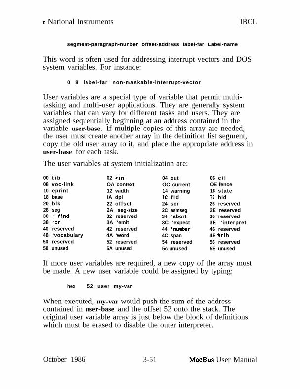
Q National Instruments IBCL
segment-paragraph-nunber offset-address label-far Label-name
This word is often used for addressing interrupt vectors and DOSsystem variables. For instance:
0 8 label-far non-maskable-interrupt-vector
User variables are a special type of variable that permit multi-tasking and multi-user applications. They are generally systemvariables that can vary for different tasks and users. They areassigned sequentially beginning at an address contained in thevariable user-base. If multiple copies of this array are needed,the user must create another array in the definition list segment,copy the old user array to it, and place the appropriate address inuser-base for each task.
The user variables at system initialization are:
00 t i b08 voc-link10 eprint18 base20 blk28 seg30 ‘-find38 ‘cr40 reserved48 ‘vocabulary50 reserved58 unused
02 >inOA context12 widthIA dpl22 offset2A seg-size32 reserved3A ‘emit42 reserved4A ‘word52 reserved5A unused
04 outOC current14 warningIC f l d24 scr2C asmseg34 ‘abort3C ‘expect44 lnunber4C span54 reserved5c unused
06 c / lOE fence16 state1E hld26 reserved2E reserved36 reserved3E ‘interpret46 reserved4E #tib56 reserved5E unused
If more user variables are required, a new copy of the array mustbe made. A new user variable could be assigned by typing:
hex 52 user my-var
When executed, my-var would push the sum of the addresscontained in user-base and the offset 52 onto the stack. Theoriginal user variable array is just below the block of definitionswhich must be erased to disable the outer interpreter.
October 1986 3-51 MacBus User Manual

IBCL 0 National Instruments
Vocabularies
An IBCL system initially contains a single vocabulary named ibcl.New words are added to this vocabulary as they are defined. It ispossible to create additional vocabularies and to limit the scope ofword searches to one of the additional vocabularies followed bythe IBCL vocabulary.
In IBCL, the three primary parts of a definition are split intothree separate segments. Machine code for all vocabulariesoccupies the codes segment. High level definition lists occupy thelists segment. The word’s ASCII representation, along with itsimmediate flag and definition list pointer occupy another segment,with words from different vocabularies accumulating in their ownprivate segments. The IBCLS segment contains the IBCLvocabulary. Creation of new segments for new vocabularies isautomatic. The number of bytes to be allocated is contained inthe user variable seg-size. This variable is initially set to fourkilobytes, but may be reset by the user.
To change the default segment size type:
new-size seg-size !
If the previous default size is adequate, a new vocabulary and itssegment may be created by typing:
vocabulary new-vocabulary-name
for instance:
vocabulary assembler
The segment name will be the vocabulary name with -segappended. The example would create the empty assemblervocabulary in the assembler-seg segment.
To cause the assembler vocabulary to be searched before the IBCLvocabulary, type:
MacBus User Manual 3-52 October 1986

Q National Instruments IBCL
assembler
At this point, no words will be found in the assembler vocabulary,but the user variable context will contain a pointer to it ratherthan to the IBCL vocabulary. New definitions would still beassigned to the IBCL vocabulary.
To cause new definitions to be assigned to the context vocabulary,type:
definitions
Now the user variable current points to the assembler vocabularyinstead of the IBCL vocabulary. current governs whichvocabulary receives new definitions. Had we wanted to enter newdefinitions in my-words, but limit our interpreter searches toIBCL, we would have had to type:
vocabulary my-words my-words definitions assembler
This would have reset context to point to assembler. Caution,entering a colon definition sets context to current.
In the course of defining new words, you may discover that youhave made a mistake. Words can be forgotten and dictionaryspace can be recovered by typing:
forget word-to-forget-thru
This type of forget may only be used in the newest vocabulary. Ifthat vocabulary is still IBCL, the user variable fence contains apointer to a word below which forgetting is disabled, to protectyou from forgetting the system.
A more general forget supports switching from one application toanother. It requires you to create a task boundary before youdefine the applications vocabularies, segments, and words. It canrecover both segments and portions of segments allocated after theboundary. Before entering the application, type:
October 1986 3-53 MacBus User Manual

IBCL
task name-of-task
o National Instruments
Forget back to the boundary by typing:
name-of-task forget-task
Segment relocation is not affected.
One task boundary is included in the system. Typing:
empty forget-task
will forget all words, vocabularies, and segments entered by theuser. This will reclaim memory from all non-system words andsegments, but will not restore system segments to their originalpositions in physical memory. empty is preserved by forget-taskbut user task names are forgotten along with the task.
Program Segments
IBCL provides limited automatic segment management. The goalis not to provide completely general segment management, but toprovide the most economical set of words that still supports use ofthe entire address space. Words are provided for the creation ofnew segments.
Initially the IBCL system occupies four segments. The names ofthese segments are variables that return the address of the firstword of the five word segment descriptor table:
1. Segment paragraph number. Absolute address of first byteof segment divided by 16
2. Maximum number of bytes allocated to this segment.3. Temporary working end of segment. Address of bottom of
stack for stack segments4. End of segment. Current stack pointer for stack segments.5. Link to first word of segment descriptor for previously
defined segment.
MacBus User Manual 3-54 October 1986

o National Instruments IBCL
The segment names are:
codesstacks
lists
ibcls
machine code segmentstack segment, return stack at bottomdata stack at topdefinition list segment, code address followedby parameter field entries, if anyASCII representation of words
The memory variable returns the address of the four wordmemory descriptor table:
1. Paragraph at which user memory starts, base of codes.Paragraphs below this one belong to IBCL.
2. Last available paragraph, set by system board switches.3. Paragraph at which free memory begins. Initially end of
IBCL, updated as new segments are allocated.4. Pointer to first word of most recently created segment
descriptor, this address is returned by last-seg.
To create a new segment, type:
size-in-bytes segment name-of-new-segment
The maximum size is 64K. An error message is generated if anattempt is made to exceed memory limits. segment uses anotherword which allocates additional memory and updates memory, butdoes not create a new segment descriptor. This word can be usedto increase the length of the top memory segment. The initial lastsegment is the lists segment which usually requires the most space.Its initial space allocation is limited by the need for the system totit into systems with only 64K bytes of memory.
size- in-bytes dup allot-seg last-seg 2+ +!
The last line updates the memory limit for the last segment. Becertain that the old value and your increase do not exceed 64K orit will wrap around to a low value. For extra protection, use the
October 1986 3-55 MacBus User Manual

IBCL o National Instruments
following definition:
: grow l a s t - s e g 2+ d d u p ad d u p I+ u< abortI’ a l r e a d y LargeP
allot-seg ! ;
final-size grow
Two temporary user variables are provided for segment values:seg and seg-size. seg may hold the address of some segmentdescriptor. seg-size should contain a default segment size. It isused by vocabulary to set the size of any new vocabularysegments.
Defining Defining Words
Two actions must be specified when defining defining words. Thefirst is executed when the defining word is executed. The next isexecuted when the word defined using the defining word isexecuted. As an example, let us assume that the system does notprovide the word defining constants. One way to define thisdefining word is:
: constant create , does 0 ;
create and does> are immediate words, they execute when thedefinition is entered. The @ is compiled as usual.
To define the constant five using this defining word, type:
5 constant five
The 5 is placed on the stack and momentarily ignored. Referringto the definition of constant, the create requires a word from theinput stream. It takes the string five and adds it to the currentvocabulary, with a pointer to the next free word in the definitionlist segment. This word is initialized with a pointer to the codefor variables, and the working end of the definition list segment isincremented by two to point to the parameter field of the word
MacBus User Manual 3-56 October 1986

o National Instruments IBCL
being defined, five. Next the , takes the top value on the stack, 5,and stores it at the working end of the definition list segment, theparameter field of five, and increments the end pointer by two.Next the does> replaces the the contents of the code field with apointer to a few bytes of code created by does> each time it isused. The code has two functions. It nests the interpreter onelevel deeper, transferring control to the word after does>, and itplaces the parameter field address of the word being delined, five,on the stack. The code is executed only when five is executed.Finally, the @ is compiled and the ; causes an exit to be compiledand then terminates the definition.
When five is executed, the code created by does> is executed. Theaddress of five’s parameter field is placed on the stack and theinterpreter nests down to the @ in the definition of constant. A 5is waiting at the parameter field address, and is returned on thestack. The exit compiled by ; returns the interpreter to the nexthigher level, with the 5 remaining on the stack. Or, stated simply,executing five causes 5 to be left on the stack.
In actual practice, a word as important as constant should definewords that execute as rapidly as possible. The run time actionshould be defined at the machine code level rather than the high-level IBCL level used above. This is the technique used in IBCL:
code docon <% 53 8b Sd 02 %> end-code
or:code docon bx push. bx 2 +Idil mov. end-code
This defines the run time behavior of the defined word. Nextdefine constant itself:
: c o n s t a n t c r e a t e , ;I docon
The ;’ replaces the code field of the word being defined with thecode field of docon.
Note that does>;’ and ;code must all be used with a word thatinitiates a dictionary entry. create is presently the only system
October 1986 3-57 MacBus User Manual

IBCL o National Instruments
supplied word that performs this function,
The above example was a relatively simple use of IBCL to create adefining word. This is admittedly the most complex topic inIBCL, and the vast majority of other languages don’t even try toprovide this capability.
For a slightly more complex case, consider a double lengthconstant.
: dconstant create swap , ,does> dup @ snap 2+ @ ;hex 1234.5678 dconstant longfellow
dconstant create a double length constant named longfellow.When longfellow executes, it leaves a double length number on thestack. First 5678 is pushed onto the stack, then 1234.
segment is an example of an even more complex defining word.When a segment is being defined, space must be allotted from freememory and a segment descriptor initialized. The run time actionis the same as for a variable - the parameter field address is lefton the stack unchanged.
vocabulary is the most complex defining word in the system. Itmust allocate a segment and create definitions and descriptors forboth the segment and the vocabulary. The run time action movesthe parameter field address from the stack into context.
The only limit to the complexity and utility of words that definewords is your imagination. BASIC is one dimensionalprogramming; compiled languages with good subroutine facilitiesprovide a second dimension. IBCL with its ability to definedefining words clearly provides a third dimension. Learning touse that dimension well will give you an edge unattainable inother languages.
Internal Workings
Defining a new word increases the memory allocated in thecurrent word ASCII representation segment and the definition list
MacBus User Manual 3-58 October 1986
o National Instruments IBCL
segment. It may increase allocation in the machine code segment.While a definition is being created, the working end of segment isgreater than the verified segment end. If an error causes thedefinition to abort before completion, memory allotted in thesesegments is reclaimed. The address stored as the verified end isthe address of the start of the detinition being created.
address of address ofworking end verified end working end--------_-- _____------ --_________
(end? @)machine codes endc oldc here-cdefinition lists end1 old1 herecurrent vocabulary endw oldw here-w
nextw will return the segment and the address of the next freeword in the current vocabulary segment. A byte or word may bestored to this location from the top of the stack and endwincremented with c,words or ,words.
Error checking is performed by the following words:
?comp?csp?pairs?stack?stream
error if not compilingerror if stack position is not that in csperror if top two stack elements unequalerror if stack out of boundserror if input stream exhausted(top of stack true )
Headerless Words
IBCL provides useful features not possible in systems withconventional architectures. Since the vocabulary segments containonly names, count bytes, and pointers into the definition listsegment, the entry for each word is completely relocatable and canbe deleted when no longer needed. This can only be done with atime consuming (and often expensive) cross compiler on othersystems. The following words delete .a name or range of namesand shift the remainder of the current vocabulary segment down
October 1986 3-59 MacBus User Manual

IBCL o National Instruments
to close the gap created. lpa stands for the list pointer addressfield, the first byte pair of the vocabulary entry of a word.
lpa-of-Ist-word-name-to-delete lpa-of-Last-name <behead>
behead’ name-to-be-deletedbehead’ I name-of-lst-word-name-to-delete name-of-last
<behead> should be used with caution, if at all, since it does notcheck for valid Ipa’s, and and invalid one will crash the system.behead’ and behead” will both respond with “NOT FOUND” if theword was not found. behead” will delete all word names in thephysically sequential range. The contents of a vocabulary may bechecked with vlist.
Overlaid Code Primitives
IBCL code primitives are overlaid upon one another if the “tail” ofone happens to be identical to some other useful word. This mayalso be viewed as having code primitives with multiple entrypoints.
code stepbx inc. bx inc.code+ dup@bx push.Code+ @bx Cbxl mov. end-code
This overlay used 9 machine code bytes instead of the 22 requiredby conventional systems. end-code does not automatically clearthe jump table, so branches may occur throughout this structure.High level flow constructs must open and close within a singlecode, code+ or end-code pair.
Forget-Task
forget-task expects the parameter field address of the task on thestack. It checks for a valid task parameter field address byverifying that the preceding code field points to <dotsk>.forget-task forgets the task descriptor block created by task alongwith the associated task. It will forget segments and parts ofsegments and reclaim space for segments or for free memory that
MacBus User Manual 3-60 October 1986

o National Instruments IBCL
has been allotted since the task was declared. It cannot rearrangesegments, so segment sizes and positions should not be changedwithin the confines of a task . . forget-task pair. Otherwise theforget-task may leave gaps in the allotted segment map and mayreduce the free memory pointer to a value below that of thehighest segment actually allotted.
task name-of-taskdefinitionsdefinitions
name-of-task forget-task
October 1986 3-61 MacBus User Manual

IBCL o National Instruments
CONTROLIBCL contains high-level control structures similar to those foundin BASIC and Pascal. These perform conditional execution andrepeated execution of word blocks, and case selection. Theyeliminate the need for any program position labels such asBASICS line numbers.
Words that control the flow of program execution are used onlywithin colon definitions (Detining New Words section). They areimmediate words which execute when the colon definition is firstcompiled. Most cause branches or conditional branches to becompiled into the definition list of the word being compiled, but afew merely save an address and identifier on the stack for use bya later control word.
The branch compiled into the definition list may be a conditionalObranch or an unconditional branch. The Obranch is ignored ifthe top word on the stack is nonzero. In either case the branchfills two words in the definition list. The first, as with anycompiled word, is a pointer to the code field address of the word,in this case branch or Obranch. The second word is the byteoffset of the destination relative to the second word.
The conditional branch always uses and drops the top stack word.
Vectored execution permits words to be defined after they havebeen used in creating other definitions. It is usually useful onlywithin colon definitions.
Vectored Execution
You cannot actually include a word in a definition if that wordhas not already been defined. If the function you wish to performcannot be defined before the word in which it is used, you mustfirst define a variable that will eventually contain the code fieldaddress of the not yet defined word.
MacBus User Manual 3-62 October 1986

0 National Instruments IBCL
variable vector-name: some-word words vector-name B execute words ;: future-word words ;I future-word cfa vector-name !some-word
The vector name used in some-word compiles like any variable.When executed, it leaves its parameter field address on the stackand @ replaces that address with the variable’s contents. Thisvariable was initialized on the last line to contain the code fieldaddress of future-word. ( ’ returns the parameter field address ofthe next word in the input stream and cfa converts the parameterfield address to the code field address.) execute executes the wordwhose code field address is on the stack, just as if it had beencompiled into the definition.
Since execute is almost always preceded by @, IBCL includesexecute@ - a more efficient replacement for this pair.
These words are used when the implementation of a word mayhave to change after words which use it are defined. Systemwords with this capability are vectored through user variables.
system word user variable
-findabortcremitexpectinterpretnurbervocabularyword
l-find‘abortlcr‘emit‘expect‘interpret‘nunbet-‘vocabularyI uord
routine_ _ _ _ _ _ _<-find><abort><cm*emit><expect>*interpret*mnher><voc79><word>
These words are also necessary to fully implement recursion.They enable the creation of a circular set of definitions in whicheach word can include previously defined words as usual, but mayalso include words defined later in the sequence. Recursion is notvery eIIicient for numerical operations such as factorial evaluationbut is very efficient for symbolic manipulations.
October 1986 MacBus User Manual

0 National Instruments
Conditional Execution
The if true-phrase else false-phrase then construct is used withincolon definitions to enable a number on the stack to controlwhether or not groups of words within the definition are executed.A phrase is any list of words normally allowed in a colondefinition. If conditional or loop constructs are included, theymust be completed within the phrase. Nesting is limited only bystack size - overlapping is forbidden.
The following example will display a game score along with oneof two messages (the new score is on the stack):
: .scoredup high-score @ >i f dup high-score ! .I’ neu high score!!!l~ .else .(I your score is II
.‘I high score is II high-score @ . then ;
When .score is executed your latest score should be at the top ofthe stack. It is duplicated and compared with the old high score.The comparison sets the top number on the stack to 0 (false) ifyour score is not greater than the old high score. It sets the topnumber to a nonzero (true) value otherwise. If the number is 0,execution will branch to the words after the else. If it is nonzero,execution will continue after the if, then skip the words betweenelse and then. The true part sets the new high score, thendisplays new high score!!! and the new score. The false partdisplays your score and the old high score.
else and the words between it and then may be omitted, in whichcase no action is taken if the condition is false.
The if compiles a Obranch and puts the address of its destinationfield on the stack. It then places an identifier on the stack tosignal its presence to else or then. The else checks for if’sidentifier and issues an error message if it isn’t found. else nextcompiles an unconditional branch. It calculates the offset from theaddress on the stack to the word after the branch and stores thatoffset into the original Obranch. The address of the destinationfield of the branch is placed on the stack, followed by another
MacBus User Manual 3-64 October 1986

o National Instruments IBCL
copy of the identifier. The then aborts with an error message ifthe identifier isn’t found, but does not need to know whether itfollows an if or an else. It calculates the offset from the addresson the stack to the next free word and stores it into the previousbranch.
Loops
Loop constructing words are similar to the above words in thatthey compile branches and leave addresses on the stack. Asabove, a phrase may be any list of words normally allowed in acolon definition. If conditional or loop constructs are included,they must be completed within the phrase. Nesting is limited onlyby stack size - overlapping is forbidden.
There are three types of conditional loops:
begin phrase again
This is really an unconditional infinite loop since it has no exit.The only legal exit would be an abort or abort” within the phraseor within a word in the phrase.
begin phrase until
until is a bit like if except that it compiles a backward branch tothe beginning of the phrase. The phrase executes repeatedly untilthe top word on the stack is true (nonzero). The phrase alwaysexecutes at least once.
begin test-phrase while phrase repeat
After the test phrase is executed, the top word on the stack isexamined. If it is true (nonzero), the phrase is executed andcontrol branches back to the test-phrase. If it is false (zero), theloop is exited and execution continues after the repeat. Thesecond phrase will not execute even once if the initial test-phrasewas false.
October 1986 3-65 MacBus User Manual

IBCL o National Instruments
There are also three types of do loops:
limit start do phrase l o o p
This do loop starts execution with an index set to start andincrements that index by one for every encounter of loop. Thephrase is executed repeatedly until the index equals or exceeds thelimit using a signed comparison. The limit and start values aretaken from the data stack at execution time. While executing theloop, the index is on top of the return stack with the limit underit. You may use the return stack within the phrase, but itscondition at the end of the phrase should be the same as at thebeginning. The data stack is not used other than on entry.
l i m i t s t a r t d o p h r a s e +Loop
This is similar to the first do loop, but the +loop takes a signednumber from the data stack and adds this to the index instead ofincrementing the index by one. If the increment is positive,termination is the same as for loop. If the increment is negative,execution repeats until the index is less than the limit.
l imi t star t do phrase / loop
This is similar to the above loops, but /loop takes an unsignednumber from the data stack and adds this to the index instead ofone. The limit and start values are naturally unsigned also.
Several words are useful only within the above do loops.
i Place a copy of the index on the data stack.
0,1 Place a copy of the index on the data stack.(Assuming it has been buried one deep and isthe second element on the return stack)
j Place a copy of the index of the next outer doloop on the data stack. (The index should bethe third word on the return stack)
MacBus User Manual 3-66 October 1986

o National Instruments IBCL
leave Set the index equal to the limit, causing exitof this do loop when execution of the phrasecompletes.
Case
Machine code level support is provided for implementing efficientcase statements. The word match signifies that the required casehas been found and execution should skip the next higher levelcolon definition. This often avoids the necessity of deeply nestedif . . . else . . . then clauses.
These examples assume a temperature is available on the stack:
: ?hot: ?cold: ?good: goldy
dup high-temp @ > ;
duP Low-temp &I < ;dup good-temp @ = ;?hoti f .‘I This porridge is too hot!’else ?cold
if .I8 This porridge is too cold!11else ?GODD
if .‘I This porridge is just right!”else .‘I Oh well, it will do.”then then then drop ;
: hot ?hot if .I8 This porridge is too hot!” drop match then ;: cold ?cold if .‘I This porridge is too cold!b1 drop match then ;: good ?good if .I1 This porridge is just right!” drop match then ;: f ine .I’ Oh well, it will do.” drop match ;: goldy hot cold good fine ;
The version using match is much easier to read. Execution exitsgoldy after finding a single match. Words in goldy beyond thematch are not entered. match itself including its copy of theinner interpreter next routine requires only 6 bytes of machinecode.
February 1987 3-67 MacBus User Manual

IBCL Q National Instruments
USING ASSEMBLY LANGUAGE FROM IBCL
MacBus uses a NEC V50 microprocessor and the NEC 72191numerical coprocessor. Most users, however, are more familiarwith the Intel 8088 and 8087 instruction sets, with which the NECchips are completely compatible. For this reason, we will use Intelmnemonics throughout the discussion below.
National Instruments supplies the assembler in IBCL source formon the Macintosh Plus diskette shipped with MacBus. In order touse the assembler, you must download the file microasm toMacBus.
The assembler is loaded by having MacBus download the utilityfile microasm. Refer to SECTION ONE - Source Code Files formore details.
If IBCL-like high-level flow control words are required and youare not loading autoopt, you must also load the control words.
The high-level flow control words are loaded by having the hostdownload the utility file hiflow. See SECTION ONE - IBCLSource Files for details.
After the assembler has been loaded, the program you are writingmay be directed to another vocabulary. The following words willcause your words to be defined in the my-words vocabulary, eventhough words in the definition are found in the microasmvocabulary.
vocabulary my-words my-words definitions microasm
If you are using the assembler to write a stand alone machine codeprogram rather than add to the IBCL primitives, you may want todirect the code to a segment other than the IBCL codes segment.The assembler will assemble code at the working end of anysegment. The user variable asmseg contains the segmentdescriptor address of the current assembly segment. Initially itpoints to codes. To create a new segment and assemble ouroriginal example into it, type:
MacBus User Manual 3-68 February 1987

Q National Instruments IBCL
500 segment my-codemy-code esmseg !>>>far my-entry
(create new segment to receive code)(redirect new code definitions)(my-entry will return address)(of next byte of code assembled)(in this segment.)
(assembly)( code)( definitions)here-c oldc !codes asmseg !
(set segment end to working end )(rest to system codes segment )
Remember to reset the code definition segment to codes in caseany future definitions generate code in the IBCL machine codesegment codes. >mfar creates a label named my-entry.Execution of this label will return the segment paragraph numberand offset with that segment for use by future calls and jumps.The here-c oldc ! sequence sets a fence below which future errorswill not reclaim memory. Without it an error assembling n’thsubroutine would reclaim the entire segment instead of just thespace allotted to that word. The end-code terminating word of acode definition provides this function when defining IBCL codeprimitive words.
Usually code should only be used when asmseg points to codes. Ifyou need more than 64K of pure code, export your longerroutines and call them through the codes segment. Overhead usingthis method is negligible. One exception is that asmseg may pointto an alternate segment to create a special purpose codes segmentthat will later replace the original IBCL codes segment. ReplacingIBCL system segments is an advanced capability best left toexperienced programmers familiar with the system.
Assembler Mnemonics
The assembler accepts mnemonics similar to those of the IBM-PCMacroassembler. The main difference is that operands are listedbefore operators, and operators other than jumps end with aperiod. If you also choose to end your jump label names with aperiod, this leads to an instruction syntax that resembles sentences,and is easier to read than typical Forth assembly language. The
October 1986 3-69 MacBus User Manual

IBCL o National Instruments
following simple example defines a word that adds the contents ofvariables x and y and stores the result in z.
codeadd ax x+tlmov. axy+Cl add. 2 +tl ax mov. end-code
First specify the destination, then the source, then the operator.The +[I operand assembles an offset without base or index register.Some operators have only a source or destination, or an operandthat is both. The operand is always typed before the operator,with the exception of labels for jump and label operators. If anoffset or an immediate value is required, it is taken from the datastack.
The complete Intel NEC V4O/V50 instruction set is supported.This assembler may be used to write any program that could bewritten with any conventional assembler.
Macro Definition
Macro capability is inherent by the very nature of IBCL. Thesource code sequence forming the macro is used in a colondefinition to define the macro. Any element in the code sequencemay be replaced with a dummy entry created by the definingword param. All dummy entries must be set before the macro isused by a code definition. For the above example let us assumethat the temporary register ax may vary:
: param create does cfa execute ; (ut i l i ty )
param tenp: mat-add temp x +I1 mov. temp y +Cl add.
z+n t e m p m o v . ; (adder macro)I ax ’ tenp !code add mat-add end- code (use ax)’ dx ’ temp !code add-dx mat-add end-code (use dx)
MacBus User Manual 3-70 October 1986

o National Instruments IBCL
Branch Control
The assembler provides high-level branch control similar to IBCLcontrol structures in function, but implemented in an altogetherdifferent manner. Do not use the IBCL control words inside theassembler. The assembler control words end with a period.
Machine level branch control is also available for both forwardand reverse branches. A jump table of hex 80 bytes is provided.This value may be increased by editing the value of jmp-lim inthe microasm file. Each label requires space for the number ofcharacters in the label plus 3 bytes. An entry occurs for eachnon-reconcilable reference to a label. When a label’s locationbecomes known, these entries are removed and an entry for thelabel itself is created. The definition of the word that returns theabsolute value of a number on the stack illustrates label andbranch syntax.
code absbx bx or. jns positive. bx neg. >>> positive. end-code
The period ending the labels is a strongly encouraged convention.It ensures that all operational units end with the same visual cue.The label is not an IBCL word, but a string argument for thejump or label operator. The label operator >>> makes labellocations easy to spot at a glance.
Things to Remember
When learning assembly language from an IBCL system, rememberthat you have a marvelous tool that lets you learn in small steps,and that enables you to check your understanding at the end ofevery step. Learning assembly language has never been so easy.While you are learning, remember that IBCL uses all the registerswhile interpreting from word to word except for ax, cx, dx, di,and es. These five registers may be used within your practicemachine code words without crashing the system. The remainingregisters would have to be saved and restored - fine if you are anexpert but unnecessary if you are learning. Even experts would
October 1986 3-71 MacBus User Manual

IBCL o National Instruments
first look for a way to avoid the overhead of first saving a registerto memory and then restoring it. The five free registers may bechanged within any word, don’t count on their values across wordboundaries unless you know the structure of the interveningwords.
NEC V4O/V50 Architecture
Registers
Now for a word on the NEC V50. You already know that youhave up to a megabyte of memory that can be addressed by aparagraph number and an offset. The most common addressingmode assumes the lists segment for a default paragraph number -you only need to provide the offset to store and retrieve 16-bitand occasionally 8-bit numbers. In assembly language you have adozen more addresses at which your numbers may be stored.They are not addressed by number, but by a two character name.The addresses of the 16-bit registers are:
;“xcxdxbpSPsidics
:
top element of the stack is at bx
offset into stack segment of top of return stackoffset into stack segment of top of data stackoffset into lists segment of word to execute next
paragraph number of code segment (codes)paragraph number of stack segment (stacks)paragraph number of definition list segment (lists)
es
The first four 16-bit registers may also be addressed as thoughthey were eight 8-bit registers. They are split into high andlow-order halves.
ah al bh bl ch cl dh dl
MacBus User Manual 3-72 October 1986

o National Instruments IBCL
Remember that bh holds the high-order half of the top word ofthe data stack and bl holds the low-order half. bh and bl are notseparate registers from bx, but only a way to address it a byte at atime.
All registers except the segment registers may be used as source ordestination for most math and logic operations. The byteaccumulator al or the word accumulator ax is always the assumeddestination for multiplication and division. The segment registersare restricted to mov. push. and pop. operations.
Memory Addressing
Some of the registers may also be used to provide an offset into asegment for memory addressing. The simplest example is the codefor @ which replaces the top word on the stack with the numberat that offset in the definition list segment.
code @ b x Cbxl mov. end- code
The source is the 16-bit number at the offset found in bx. Thedestination is the top of the stack, namely the bx register. Mostoperators use the paragraph number in ds to select the segment,but any segment register may usually be explicitly selected.
c o d e @e es : bx [bxl mov. end-code
In the definition of @e, the es register is selected to provide theparagraph number. The segment selectors (cs: ss: ds: es:)immediately generate one byte of machine code, so they may alsobe used directly before the memory operand.
code @e bx es: lbxl mm. end-code
This produces the same code as above.
The following registers and combinations may be used to providememory offsets. If more than one register is used, the contents ofthe two are added in a temporary scratch register.
October 1986 3-73 MacBus User Manual

IBCL Q National Instruments
lbxl kilCdil
tbx+siltbp+sil
Cbx+dilCbpcdil
It is also possible to form an offset by adding a constant to thecontents of the above registers or combinations. If a constant is tobe added use the names below.
+tbxl +Csil +Cbx+sil +tbx+dil + [I+cbp1 +Cdil +Cbp+sil +Ibp+dil
Note that the addressing mode corresponding to [bpl does not existon this microprocessor. It has been replaced with a special mode+[I which uses a constant offset with no base register. In all casesthe constant used is the top word on the stack.
Single operand instructions need to know whether memoryoperands are bytes or words. The following instruction toincrement memory at the offset stored in bx is incomplete andgenerates an error since it does not indicate whether a byte orword should be incremented:
Cbxl inc. (error b/u?)
To specify byte or word, use one of the following:
Cbxl byte-ptr inc.tbxl word-ptr inc.
Both the source and destination may be a register, but a memoryoffset is legal for only one at a time. Attempting to use memoryoffsets for both source and destination will generate an errormessage.
For some operators, the source may be an immediate value. Inthis case the machine code created will include the immediatevalue. An immediate byte or word is declared by typing ib or i winstead of the register or offset words.
ax 339 iw mov. (store 339 into ax)dl 51 ib add. (add 51 into dl)
MacBus User Manual 3-74 October 1986

Q National Instruments IBCL
The destination can usually be either a register or memory. Theimmediate operands obviously can’t be used as destinations.
Flags
The flags and their abbreviations are as follows. Theabbreviations are not assembler words. Assembler words to setand reset the flags and move them to and from the stack and theah register are covered in the instruction section. Flags aregenerally set by math or logic operations and are unaffected bymove, stack, or control transfer instructions.
overflow of or 0direction df dinterrupt if itrap tf tsign sf S
zero zf Z
auxiliary carry a f aparity Pf Pcarry cf C
Abbreviations and Conventions
The following abbreviations are used for sets of legal operands.
b-regw-reg
regseg-regmemory
reg/memimmedaccum
ah bh ch dh al bl cl dlax bx cx dx bp sp si dib-reg or w-regcs ss ds es[bx] [si] [bx+si] . . . +[I . . . +[bp+di]reg or memoryib iwbyte or word accumulator - ax or al
Source and destination operands must both be byte or both beword length operands.
October 1986 3-75 MacBus User Manual

IBCL e National Instruments
All operands of the form +E ? ] use a number from the stack toprovide an offset relative to the contents of the registers. The iband iw operands use a number from the stack to provide theimmediate value. The operand identifier words above do not usethe stack, so no conflict exists with immediate values or offsets onthe stack. If both immediate and offset values are required, theimmediate value should either be below the offset, or preferablynot placed on the stack until just before the ib or iw. Bothnumbers are included in the machine code created for the currentoperator.
If a short 8-bit offset or immediate is legal and the value is smallenough, the assembler will generate the code for that form.
Error Messages
not foundtoo manybyte,wordmem,memimmediatesegregoperands?dest=csdest?source?2 operandsoperand ?bytecount ?too largetoo largenot ace
table fulltoo far
Attempted to use undefined word.Cannot have more than two operands.Byte and word operands cannot be combined.Source and destination cannot both be memory.Immediate operand not permitted here.Segment register not permitted here.Missing operands.Destination cannot be code segment register.Missing destination.Missing source.Instruction accepts only one operand.Single operand missing.Word operand required.Count missing for shift or rotate.Value too large for byte representation.External opcode exceeds 6 bits for ESC.Input destination or output source must bean accumulator.Jump table full.Label out of range for short relative jump.Destination must be within -128 through +127 bytesof byte following jump instruction.
MacBus User Manual 3-76 October 1986

o National Instruments IBCL
Timing
Since the main purpose of programming in assembly language is toachieve the fastest possible execution times, the clock cyclesrequired are listed along with the instructions. Often specialforms of an instruction provide significantly faster execution. If a+ follows the number of clocks, you must add a correction tonumber of clocks for that instruction. The correction depends onthe addressing mode used:
operand__----- __---
[bxl [si] [di] 5+[I 6[bx+si] P-w-W 7[bx+di] [bp+si] 8
tibxl tibpl +[si] +[di] 9+Ebx+si] +[bp+dil 11+[bx+di] +[bp+si] 12
clocks
For a word operand at an odd address, add 4 more clock cycles.
Instruction Set
Data Transfer
mov. Move a byte or word from one location to another.The source and flags are not affected.
dest____
regseg-regw-regregaccum41w
source operator clocks comment----_- _______ _____ -__-----
reg mov. 2w-reg mov. 2 cs illegal destseg-reg mov. 2 cs legal sourceimmed mov. 4+[I mov. 10accum mov. 10memory mov. 8+
October 1986 3-77 MacBus User Manual

IBCL e National Instruments
push.
POP.
xchg.
lea.
Ids.
memory reg mov. 9+memory seg-reg mov. 8+seg-reg memory mov. 9+
Push the contents of the source location onto the stack.Decrement the stack pointer sp by 2, and copy thesource contents to that address in the stack segment.Flags are not affected.
w-reg push. 10s e g - r e g p u s h . 1 0memory push. 16+
Pop the top of the stack into the destination location.Copy the word in the stack segment at offset containedin sp to the destination, and increment sp by 2. Flagsare not affected.
w-reg POP. 8seg-reg POP. 8memory POP. 17+
Exchange the byte or word source and destination operands.Flags are not affected.
accum reg xchg. 3reg reg xchg. 4memory reg xchg. 17+
Load effective address. Load the effective address ofthe source operand into the destination operand.Unlike the mov. instruction, the address rather than thecontents of that address are loaded into the destination.The flags are not affected.
w-reg memory lea. 2+
Load data segment pointer. Load the destination register
MacBus User Manual 3-78 October 1986

B National Instruments IBCL
les.
lahf.sahf.
pushf. Push the flag registers onto or pop the flag registersPOPf. from the stack. The flags occupy these bit positions:
xlat. Translate. Replace byte in al with byte at offset
from the word at the memory offset. Load the dssegment register from the next higher word. Flags arenot affected.
w-reg memory Ids. 16+
Load extra segment pointer. Load the destinationregister from the word at the memory offset. Load thees segment register from the next higher word. Flagsare not affected.
w-reg memory les. 16+
Load ah from the flag registers.Store ah to the flag registers.( sign zero ? aux-carry ? parity ? carry )The bits marked 1 are undetined
lahf. 4sahf. 4
bit 11109876420
overflow ofdirection dfinterrupt iftrap tfsign sfzero zfauxiliary carry afparity Pfcarry cfpushf. 10POPf. 8
October 1986 3-79 MacBus User Manual

IBCL o National Instruments
given by sum of bx and al. The action would beequivalent to al [bx+al] mov., except that thisinstruction is illegal. Essentially, this commandprovides an 8-bit index register. A similar but slowerinstruction with a 16-bit index register is al [bx+si]mov. Flags are not affected.
xlat. 11
in.out.
Transfer a byte or word from an input port to ax or al.Transfer a byte or word from ax or al to an output port.The port number may range from 0 through 255. Flagsare not affected.
accumaccum
port# i n .port# out .
1010
in-dx. Transfer a byte or word from an input port to ax or al.out-dx. Transfer a byte or word from ax or al to an output port.
The port number must be in dx and may range from 0through 64K. Flags are not affected.
accum in-dx. 8accum out-dx. 8
Arithmetic and Logic
Two operand instructions:
dC. Add with carry dest + source + cf o...sz ap cadd. Add dest + source o...sz ap cand. Bitwise logical AND dest AND source o...sz p c
cnp- Compare virtual (dest - source) o...sz ap c
MacBus User Manual 3-80 October 1986
Flag usage is indicated to right,using bit order as would be pushedto stack. Blank bit positions areundefined, . are unaffected.
gA987654321D

o National Instruments IBCL
or. Bitwise logical OR dest OR source o...sz p cSbb . Subtract with borrou dest - source - cf O...SL a p csub. Subtract dest - source o...sz ap cxor . gitwise exclusive OR dest XOR source o...sz p c
The above words require a destination followed bya source in one of the following forms.
dest source operand clocks__-_ ----__ __----- - - - - - -
ret3 reg xxx. 3act immed xxx. 4reg immed xxx. 4reg memory xxx. 9+memory reg xxx. 16+* memory reg cmp. 9+memory immed xxx. 17+
Flagstest. Bitwise logical AND, destination unaffected o...sz p c
rw3 reg test. 3act immed test. 4reg immed test. 4reg memory test. 9+memory reg test. 9+memory immed test. lO+
One operand instructions:
dec. Decrementinc. Incrementneg. Negatenot. Bitwise logical not
The above instructions accept one operand in one of the
October 1986 3-81 MacBus User Manual
Flagsdest - 1 o...sz a p .dest + 1 o...sz a p .2’s complement of dest o...sz a p cl’s complement of dest . . . . . . . . .

IBCL o National Instruments
following forms:
dest- - - -
regmemory byte-ptrmemory word-ptr
operand- - - - - _ -xxx.xxxxxx
clocks___---316+16+
For the multiplication and division instructions, an accumulator isalways the destination. The high-order extension of the alaccumulator is the ah register. The high-order extension of theax accumulator is the dx register. For multiplication, theaccumulator is multiplied by the source and the result overflowsinto the extension if necessary. For division, the numerator is adouble length number held in the accumulator and its extension.A single length signed numerator may be converted to doublelength by cbw. or cwd. (convert byte to word or convert word todouble word). The extension for an unsigned numerator may beset to zero.
The remainder is left in the extension register and has the samesign as the numerator. The quotient is left in the accumulator. Ifit is too large, a type 0 divide overflow interrupt is generated.
div. Unsigned division.
b-reg div.w-reg div.memory byte-ptr div.memory word-ptr div.
idiv. Signed division.
b-regw-regmemory byte-ptrmemory word-ptr
MacBus User Manual
idiv.idiv.idiv.idiv.
3-82
Flags. . .
9015590+155+
o...sz a p c
112177112+177+
October 1986

o National Instruments IBCL
mul. Unsigned multiplication. Overflow and o... C
carry flags set if extension becomes nonzero.
b-regw-regmemory byte-ptrmemory word-ptr
mul. 71mul. 124mul. 71+mul. 124+
imul. Signed multiplication. Overflow and o...carry flags set if extension is not thesign extension of the accumulator.
c
b-reg imul. 90w-reg imul. 144memory byte-ptr imul. 90+memory word-ptr imul. 144+
The following instructions accept no operands. The source anddestination, the ax or al accumulator, are implied by thecommand.
cbw. Sign extend al into ah 2 . . . . . . . . .cwd. Sign extend ax into dx 5
888. ASCII adjust after addition 4 . . . a caas. ASCII adjust after subtraction 4 . . . a caam. ASCII adjust after multiplication 83 . ..sz paad. ASCII adjust after division 60 . ..sz p
daa. Decimal adjust after addition. 4 . ..sz a p cdas. Decimal adjust after subtraction. 4 . ..sz a p c
The ASCII adjust operations are used to correct theaccumulator after arithmetic on unpacked decimalnumbers, numbers with one decimal digit per byte. al mayexceed the value of a legal decimal digit after such anoperation. These operators store the legal higher order
October 1986 3-83 MacBus User Manual

IBCL o National Instruments
digit in ah, leaving al within the 0 to 9 range.
The decimal adjust operations perform a similar functionfor packed binary coded decimal where each half of alstores a separate decimal digit.
Rotate and Shift
The rotate and shift instructions accept a single location operandand a number from the stack to indicate a single or a multiple bitshift. The number from the stack is not actually used to set theshift count, but only to select the single versus multiple bitmachine code pattern. A one on the stack will select the single bitshift, anything else will select multiple. For multiple bit shifts,the count must have been set in the cl register by some previousinstruction.
Rotation causes bits that are forced out one end of the byte orword to be reinserted at the other. Bits that are forced out by ashift never reenter the operand. Bits forced out of either end ofany operand are moved into the carry flag cf.
Note: If count is not one, the overflow flag of is undefined. Forright shifts and rotates by one the overflow flag is set to one onlyif the two new high-order bits are unequal. For left shifts androtates by one the overflow flag is set to one only if the newhigh-order bit does not equal the carry flag.
Flagsrol. Rotate left, high-order bit to low. 0 . . . . . . . C
for. Rotate right, low-order bit to high. 0 . . . . . . . C
rcl. Like rol. but cf is included in the circle. o . . . . . . . crcr. Like ror. but cf is included in the circle. o . . . . . . . . cshl. Shift left, zero low-order bit. o...sz PCshr. Shift logical right, zero high-order bit. o...sz PC
The above instructions accept one operand and a count onthe stack in one of the following formats. The count mayfollow the operand or may already be on the stack.
MacBus User Manual 3-84 October 1986

o National Instruments IBCL
dest count operator---_ ----_ _______reg 1 xxx.reg 2..15 x x x .memory byte-ptr 1 xxx.memory word-ptr 1 xxx.memory byte-ptr 2..15 x x x .memory word-ptr 2..15 x x x .
clocks- - - - -28 +4 per bit15+15+20+ +4 per bit20+ +4 per bit
String Manipulation
The string manipulation instructions accept no operands. Registerusage is implied by the instruction. Generally the data segment,extra segment, source and destination registers (ds es si di) mustbe set by previous instructions. In some cases one of the defaultsegment registers may be replaced by an explicit declaration usingthe segment register prefixes (cs: ss: ds: es:). These may be used inconjunction with the repeat prefix (repx.) and/or the bus lockprefix (lock:). If more than one prefix is used, interrupts must bedisabled. The return from an interrupt returns control to at mostone prefix byte before the instruction.
Both byte and word versions of all string operators exist.
The source string defaults to the data segment at the offset givenby the source index register. The segment may be over-ridden byan explicit segment prefix. The destination string is always in theextra segment at the offset given by the destination index register.If the operation has a repeat prefix, the repeat count must havebeen placed in the cx register by a previous instruction. Therepeat prefix will cause the following string operator to berepeated and cx decremented by one until cx reaches zero. If thestring operator is cmpsx. or scasx., the operation will be endedprematurely if the zero flag becomes set when using repz: or repe:or if the zero flag becomes zero when using repnz: or repne:.
After each operation, the si and di registers are incremented if thedirection flag is clear and decremented if the direction flag is set.The delta is one for byte operators and two for word operators.
October 1986 3-85 MacBus User Manual

IBCL o National Instruments
clocks
movsb.movsw.
cmpsb.cmpsw.
__---1717
2222
Move byte (word) string. Transfer byte (word)from source to destination . . . . . . . . . .
Compare byte (word) string. For this compare,the destination is subtracted from the sourcebut only the flags are affected.o...sza p c
lodsb.lodsw.
1212
Load byte (word) string. Transfer byte (word) toaccumulator al or ah from source . . . . . . . . . .di not used or affected.
stosb.stosw.
1010
Store byte (word) string. Transfer byte (word)from accumulator to destination . . . . . . . . . .si is not used or affected.
scasb.scasw.
1515
Scan byte (word) string. For this compare,the destination is subtracted fromthe accumulator but only the flagsare affected. si is not used oraffected.o...sza p c
repz: 6repe: 6repnz: 6repne: 6
Repeat following string operation until cx becomeszero, decrementing cx each iteration. Terminaterepz: or repe: if zero flag becomes one.Terminate repnz: or repne: if zero flag becomeszero. Premature termination possible only forcompsb. compsw. scasb. and scasw.
Jumps, Calls, and Loops
There are two formats for jumps and calls. Calls, indirect jumps,and intersegment jumps follow the usual operand first syntax.Intrasegment direct jumps, both conditional and unconditional, arefollowed by the target label. Loops are like conditional jumpsexcept that a count in the cx register is decremented by one. Thebranch is taken only if the cx register has not become zero.
MacBus User Manual 3-86 October 1986

Q National Instruments IBCL
The segment and offset for intersegment direct jumps and calls aremost easily provided by creating a label with nsfar. Suppose weare assembling code into an auxiliary segment and want the targetof a direct call or jump to be within that code:
previous code >>>far come-here remainder of codethen
come-here callf.
will assemble a far call to come-here.
Calls push the offset of the next instruction onto the stack. Forintersegment calls the cs register is pushed first. Control thentransfers to the target location.
Calls may be direct or indirect, intrasegment or intersegment. Fordirect calls, the destination offset is on the stack. The targetsegment is next on the stack for far calls.
For indirect calls the usual destination operand format is used.clocks
offset call. 11 Call intrasegment direct.reg calli. 13 Call intrasegment indirect.memory calli. 13+ Call intrasegment indirect.
segment offset callf. 20 Call intersegment direct.memory callfi. 29+ Call intersegment indirect.
A called subroutine may return control to the instruction after thecall by using a return instruction. The top stack value is poppedinto the instruction pointer. For far returns the next stack valueis popped into the code segment register. If the return containedthe + character, it was assembled with a number from the stackwhich will be added to the stack pointer sp to discard parameters.The number should be even, since all stack operations are onwords.
Intrasegement returns must be used with intrasegment calls, andfar (intersegment) returns must be used with far calls.
October 1986 MacBus User Manual

IBCL o National Instruments
#bytes-drop
#bytes-drop
ret. 8ret+. 12
retf+. 17
Intrasegment return.Intrasegment return,add immediate to sp.Intersegment return,add immediate to sp.
Unconditional jumps may be direct or indirect, intrasegment orintersegment. For direct intersegment jumps, the destination offsetand target segment are on the stack. For indirect jumps, the usualdestination operand format is used. Direct intrasegment jumps arecovered with conditional jumps.
segment offset jmpf. 7 Jump intersegment direct.reg jmpi. 7 Jump intrasegment indirect.memory jmpi. 7+ Jump intrasegment indirect.memory jmpti. 16+ Jump intersegment indirect,
Conditional and unconditional intrasegment jumps transfer to alocation at an offset relative to their own position. Use of a jumptable to reconcile jumps and targets prevents any space from beingpermanently lost in the dictionary. The table is necessary sincethe location of forward jumps is unknown until the target label isassembled.
The relative offset of the unconditional jump jmp allows access tothe full segment. Offsets for the conditional jumps, and the shortform of the unconditional jump, must be within -128 through+127 bytes of the next instruction.
There is only one label defining word for these jumps. It does notdirectly assemble any machine code, but creates an entry in thejump table consisting of the label’s length, name string, andabsolute offset within the current codeseg segment.
If any jumps have previously used this label, their entries in thejump table are used to insert the correct offset in their code andthe entry is removed. Future references to that label by otherjumps immediately enter the correct offset and no further tableentries are created. The jump table may be cleared by setting its
MacBus User Manual 3-88 October 1986

o National Instruments IBCL
first word, number of entries, to zero.
0 jmp-tab !
The constant jmp-lim contains the number of bytes allotted forjmp-tab. It should be sufficient for defining IBCL primitives ofany reasonable size, but the value in the file may be edited toprovide sufficient room to use the assembler to create programs ofany size.
To create a label, type:
>>> label-name.
The >>> string (pronounced label) makes labels easy to spot. Thesame string can be reused for a new label only if the jump tablehas been cleared. To clear the jump table, set the first word ofjmp-tab to zero. The jump table is not automatically cleared byterminating one code primitive or beginning another.
Since labels are just entries in the jump table, they cannot conflictwith IBCL words. All labels defined using >>> should end with aperiod to make your programs more readable. This is aconvention, not a requirement.
NOTE: The operator for these instructions does not end with aperiod. It is not the end of the instruction.
All direct intrasegment jumps and loops follow the form:
jvrp-operator label-name
For instance, the primitive to return the absolute value of anumber on the stack:
code absbx bx or. jns positive. bx neg. >>> positive. end-code
clocks_____
jmp 7 Unconditional direct
October 1986 3-89
jump. Only jump with
MacBus User Manual

IBCL o National Instruments
label that may be anywhere in segment. Longform of relative offset always used.
xxxxxx
8 If jump is taken.4 If jump is not taken.
The remaining jumps are conditional and the destination labelmust be within -128 through +127 bytes of the byte after thejump. The conditions for taking a jump are given both as flagsettings and relation of destination to source. The latter form isrelevant following a subtract or compare operation.
Jump if . . . . . , dest is . . . . . . . . source.
3jaej bjbejcjcxzjejgjgej ljlejmpsjnajnaejnbjnbejncjnejngjngejnljnlejnojnp
cf=O and zf=O abovecf=O above or equal tocf=l belowcf=l or zf=l below or equal tocf=l belowcx=o ( if count is zero)zf= 1 equal tosf=of and zf=O greater thansf=of greater than or equal tosf of less thansf of or zf=l less than or equal tounconditional, shortcf=l or zf=l not abovecf= 1 not above or equal tocf=O not belowcf=zf=O not below or equal tocf=Ozf=O not equal tosf of or zf=l not greater thansf of not greater than or equal tosf=of not less thansf=of and zf=O not less than or equal toof=0 (jump if no overflow)pf=O ( parity odd)
MacBus User Manual 3-90 October 1986

o National Instruments IBCL
jnsjnzjojpjpejpojsjz
sf=Ozf=Oof= 1pf= 1pf= 1pf=Osf=lZF= 1
( no sign)( not zero)
(jump if overflow set)( parity even)( parity even)( parity odd)
( negative)( zero)
Above and below refer to unsigned numbers.Greater than and less than refer to signed numbers.
loopcxloopeloopzloopneloopnz
cxcx and zf=lcx and zf=lcx and zf=Ocx and zf=O
Loop (jump) if cx is not zero.Loop if equal.Loop if zero.Loop if not equal.Loop if not zero.
Conditional Execution & Loops
The high-level flow control words parallel the high-level flowcontrol words of IBCL. They are used by the assembler. Theymay be loaded from hiflow. Since the purpose of these packagesis fast execution, we also include minor variations of the controlwords that are more efficient in some instances. The source codeis provided on disk in file hiflow, enabling you to create controlwords tailored to your particular needs.
The primary variation is a set of words that does not pop thestack when testing a conditional. Recall that in IBCL the top ofthe stack is in the bx register. This is the register that theconditionals check. Its contents are usually lost when the nextelement is popped into it. Often the flag word is used within anif or a loop and the control word would have to be preceded by adup to provide an extra copy. Another variation is easy to writebut too numerous for including a complete set. For these thecondition refers to the flags left by the previous instruction, forinstance:
October 1986 3-91 MacBus User Manual

IBCL o National Instruments
begin. cx bx cmp. uhi le-below. cbxl 0 ib nw. bx inc. repeat.
The condition name is taken from the related conditional jumpname.
All code class high-level flow control words end with a period tomaintain consistency with the assembler. The flow control wordsthat do not drop the word on top of the stack include a minussign. These words use the stack for branch and target addressesand for tags to check matching errors. The compile time stackbeyond the most recent flow control word should be consideredinaccessible. The execute time stack is used as noted in theindividual words. Nesting on all of these words is limited only bystack space.
First Terminatorsword
if. tt then.
if. tt else. ff then.
if-t. tt then.
if-t. tt else. ff then.
begin. bb again.
begin. bb until.
MacBus User Manual
NOTE: bx is the top stack word.sp points to the second.
Code tt executes if bx is nonzero.Next stack word pops into bx.
Code tt executes if bx is nonzero.Code ff executes if bx is zero.Next stack word pops into bx.
Code tt executes if bx is nonzero.bx unchanged.
Code tt executes if bx is nonzero.Code ff executes if bx is zero.bx unchanged.
Infinite loop, stack not used.
Code bb repeatedly executesuntil bx is nonzero entering until.Next stack word is pops into bxon every pass through until.
3-92 October 1986

Q National Instruments IBCL
begin. bb
begin. cc
begin. cc
begin. cc
do.
do-.
until-t. Like until., but bx preserved.
while. bb repeat.Loop exits when bx is zero enteringwhile. Next stack word pops intobx on every pass through while.
while-t. bb repeat.Like while. except bx preserved.
while-below. bb repeat.Like while-t. except loop exitswhen carry flag is clear.
Push si, then di, onto return stack.Pop initial value from data stack(bx) into di, pop limit into si, popthird stack word into bx.
loop.
+loop.
Like do. but initial value remainson stack (in bx). Limit is stillremoved from stack.
Either form of do. may be used withany of the following do loopterminators.
Increment di. If di less than si,branch back to code after do.Otherwise pop the top of the returnstack into di, and next word into si,and continue executing after loop.
Like loop. but the value in the bxregister is added to di instead of 1.If the increment is negative, theloop is repeated until the count isless than the limit.
October 1986 3-93 MacBus User Manual

IBCL o National Instruments
+loop-.
/loop.
The next data stack word is poppedinto bx.
Like +loop. but the increment isretained in bx.
Add value in bx to di. If di isbelow limit (unsigned), branch backto code after do.Otherwise pop the top of the returnstack into di, and next word into si,and continue executing after /loop.The next data stack word is poppedinto bx.
/loop-. Like /loop. but the increment isretained in bx.
Words to use inside do loops.
leave. Set di to si, terminating loop atnext pass through loop terminator.
i. Push count onto data stack.(Push bx, then copy di to bx)
i. Push count of next outer do looponto data stack.(Push bx, then copy top of returnstack to bx)
MacBus User Manual 3-94 October 1986

o National Instruments IBCL
Processor Control
These instructions have no operands, the operator is sufficient togenerate the code.
hlt.
clocks-_---
2 Cause cpu to enter halt state. This state may becleared by an enabled external interrupt or by asystem reset.
lock: 2 Bus lock prefix. The processor’s bus-locksignal will be asserted for the duration of theoperations caused by the following instruction.Used in multiprocessor systems to control accessto shared resources. For instance, the followingsequence will wait for some resource to becomeavailable, signaled by a non-zero value in thevariable free?.
code wait m> notyet.al al xor.
lock: free? +[I al xchg.al al test.jz notyet.end-code
code release free? +[I 0 ib mov.end-code
nop. 3 No operation. Implemented as ax ax xchg.
CIC.
stc.cmc.
2 Clear carry flag.2 Set carry flag.2 Complement carry flag.
October 1986 3-95 MacBus User Manual

IBCL o National Instruments
cld.std.
2 Clear direction flag, set to ascending.2 Set direction flag, set to descending.
cli. 2 Clear interrupt flag, disable maskableexternal interrupts.
sti. 2 Set interrupt flag, enable maskableexternal interrupts.
MacBus User Manual 3-96 October 1986

e, National Instruments IBCL
Interrupts
Interrupts may be generated by software to transfer controlthrough any of 256 vectors at the bottom of memory. The addressof the vector transferred through is four times the interruptnumber. For instance, the vector for interrupt 3 is at location 12decimal. The first word at this location holds the segmentparagraph number into which control is transferred. The secondword holds the offset into that segment of the entry of theinterrupt handler. See the IBM Technical Reference Manual or itsequivalent for your computer for system interrupt usage.Interrupts between 128 and 255 are listed in the BIOS memorymap as available for independent use.
int.
into.
iret.
Push the flag registers on the stack, clear tf and if(trap and interrupt flags), and transfer control as iffor indirect intersegment call through vector element.
clocks--___
interrupt-number int. 503 int. 51
Generate interrupt 4 if overflow
into. 524
(breakpoint interrupt)
flag (of) is set.
(overflow flag set)(overflow flag not set)
Perform intersegment return, then pop next stack wordinto flags. This restoreshad before the interruptroutine.
iret.
the flags to the values theywhich caused entry into this
24
October 1986 3-97 MacBus User Manual

IBCL o National Instruments
CoProcessor Support
est. This instruction forms the base for all NEC 72191numeric coprocessor instructions. It requires a 6bit number (0 through 63) on the stack to use as theopcode for the coprocessor instruction. Theinstruction also requires either a memory operand( [XXI or +Dxl 1 or a second number on the stack.The second number selects either one of the eightNEC 72191 stack registers or one of eight specificcommands for the given opcode. In both cases thepossible values are 0 through 7. The top register ofthe NEC 72191 stack is 0, the one under it is 1.
ormemory 0..63 est.
0..7 0..63 est.
You will not normally need to use this instructionsince complete NEC 72191 instruction mnemonics areprovided in the 72191asm file.
wait.fwait.
These instructions are the same. The fwait. version isjust a reminder that the floating point processor is thecause of the delay. The primary processor must notaccess any memory location that the coprocessor isattempting to read or to write. The primaryprocessor is free to read or write other memorylocations. The coprocessor must not be given a newinstruction until the previous one has been completed.This last requirement is met automatically byinstructions using NEC 7219 1 mnemonics from the72191asm file - they all code an fwait. precedingeach instruction.
Omission of fwait. wherever needed to prevent memoryconflicts, can produce random bugs which are extremelydifficult to detect. The logic may be flawless, but ifthe result isn’t ready it will be wrong.
MacBus User Manual 3-98 October 1986
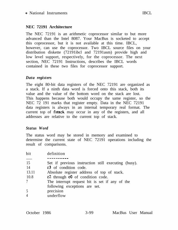
Q National Instruments IBCL
NEC 72191 Architecture
The NEC 72191 is an arithmetic coprocessor similar to but moreadvanced than the Intel 8087. Your MacBus is socketed to acceptthis coprocessor, but it is not available at this time. IBCL,however, can use the coprocessor. Two IBCL source files on yourdistribution diskette (72191ibcl and 72191asm) provide high andlow level support, respectively, for the coprocessor. The nextsection, NEC 72191 Instructions, describes the IBCL wordscontained in these two files for coprocessor support.
Data registers
The eight 80-bit data registers of the NEC 72191 are organized asa stack. If a ninth data word is forced onto this stack, both itsvalue and the value of the bottom word on the stack are lost.This happens because both would occupy the same register, so theNEC 72 191 marks that register empty. Data in the NEC 72191data registers is always in an internal temporary real format. Thecurrent top of fstack may occur in any of the registers, and alladdresses are relative to the current top of stack.
Status Word
The status word may be stored in memory and examined todetermine the current state of NEC 72191 operations including theresult of comparisons.
bit definition___151413.1110.87
Set if previous instruction still executing (busy).c3 of condition code.Absolute register address of top of stack.c2 through CO of condition code.The interrupt request bit is set if any of thefollowing exceptions are set.precisionunderflow
54
October 1986 3-99 MacBus User Manual

IBCL
MacBus User Manual 3-100
o National Instruments
overflowzerodividedenormalized operandinvalid operation
October 1986

Q National Instruments IBCL
Control Word
A new control word may be written from memory to the NEC72191 to control its response to various conditions. Sometimes thisword is first read from the NEC 72191 into memory where onlythe bits relevant to the required change are altered. It is thenloaded from memory back into the NEC 72191.
In case of alternatives, the default is listed first.
bit- - -12
11,lO
958
definition_______---infinity control
0 projective closure (infinities equivalent)1 affine closure (-infinity < +inlinity)
rounding00 round to nearest or even01 round toward -infinity10 round toward +intinity11 truncate toward zero
precision11 64 bits00 24 bits10 53 bits
interrupt maskprecisionunderflowoverflowzerodividedenormalized operandinvalid operation
October 1986 3-101 MacBus User Manual

IBCL o National Instruments
Tag Word
The tag word contains a 2-bit code for each of the eight dataregisters. The first 2 bits are for register 7 (absolute) and the last2 bits for register 0.
000110
11
valid nonzerovalid zerospecial(zero, unnormal, infinity, indefinite, ornot a number)empty
Registers are emptyassigned or freed asstack.
when the coprocessor is initialized and arenumbers are pushed and popped from the
Data Types
All numbers are stored in the NEC 72191 in the same TemporaryReal format. Instructions that require a memory reference willread or write a number at the memory location using one of thefollowing data types.
Note: The packed decimal, long integer, and temporary realdata types are used only by fld. and fstp. load andstore instructions.
Type # bits____ ______Word Integer 16Short Integer 32Long Integer 64Packed Decimal 80
range_____-32768 through 32767-2,147,483,648 through 2,147,483,647-9*10**18 through 9*10**1818 digits (signed)
MacBus User Manual 3-102 October 1986

o National Instruments IBCL
exponent#bits bias---____---
Short Real 32 8 127 6 or 7 digitslo**-37 to lo**38
Long Real 64 11 1023 15 or 16 digitslo**-307 to lo**308
Temporary Real 80 15 16383 19 digits1 O**-4932 to lo**4932
The least significant byte is always at the lowest addressedmemory location. All integers are in the usual 2’s complementform. Only the high-order bit of highest addressed byte of apacked decimal is significant - it is set for negative numbers.The corresponding bit is also set to indicate negative real numbers,but it is immediately followed by an exponent. The leading bit ofthe magnitude is explicit in temporary real format, but leftunderstood in the other real formats.
IBCL’s scaled decimal package interfaces through the short integerdata type. The precision of this interface is more than adequatefor entering and printing most numbers, and the decimal point ishandled automatically. Intermediate steps could possibly requiremore precision, and this is easily accomplished using the assemblerextensions and longer data types. Be careful to allot sufficientspace to variables for the various data types.
October 1986 3-103 MacBus User Manual

IBCL o National Instruments
NEC 72191 Instructions
To use the 72191 from IBCL, you must download one of the IBCLsource files (72191ibcl or 72191asm). 72191ibcl provides a set ofhigh level IBCL words which you may use interactively or incolon definitions. You may download this file to MacBus usingthe interactive IBCLload utility or the language interface functionIBCLload. Refer to SECTION ONE - IBCL Source Files for moredetails.
Before downloading 72191asm, you must download the IBCLassembler contained in the file microasm. 72191asm containsIBCL definitions which allow you to use 72191 operations in yourIBCL assembly language definitions. This section documents thecoprocessor support facilities provided by these two utility files.
A full complement of NEC 72191 high-level IBCL words areincluded in the file 72 19 1 ibcl. They include NEC 7219 1 versionsof most stack control and memory reference words, as well ascomparisons and math from addition and subtraction through trigand log functions. Format conversion to and from the scaleddecimal accepted and printed by IBCL is also provided. Thescaled decimal package is not needed by 72191ibc1, whichduplicates those words which are useful. Duplicated wordsinclude:
sc-constant scaler SC! sc6l and SC .
Our stack notation will contain a double colon :: with the NEC72191 stack always to the right. Remember that the NEC 72191stack can only hold eight numbers. Some of the transcendentalfunctions need two extra temporary register from the NEC 72191stack for intermediate calculations.
Data Type Selection
These words set the data type assumed by memory referenceinstructions. The data type set remains in effect until changed.
MacBus User Manual 3-104 October 1986

o National Instruments IBCL
i16 Word integerr32 Short reali32 Short integerr64 Long real
i64bedtreal
Long integer fld. and fstp. onlyBinary coded decimal I,
Temporary real II
Instruction Format
The NEC 72191 mnemonics follow the usual IBCL pattern, andalways begin with f. They may be preceded by either a singleoperand or no operand. If an operand is present, it must be ofthe memory reference type or a single word integer from 0through 7 addressing one of the 8 NEC 72191 stack registersrelative to the top of the NEC 72191 on chip stack. Instructionsneeding two operands always use the top number on the NEC72191 stack for one.
n[ccl
offset +Ecc]
Fccccc.Fccccc.Fccccc.Fccccc.
[bxl]x +[bp+di]
fabs.fadd.fsub.fdiv. (x is some variable.)
October 1986 3-105 MacBus User Manual
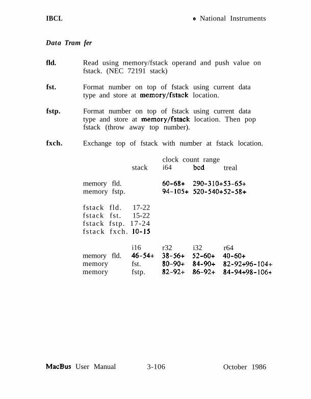
IBCL o National Instruments
Data Tram fer
fld. Read using memory/fstack operand and push value onfstack. (NEC 72191 stack)
fst. Format number on top of fstack using current datatype and store at memory/fstack location.
fstp. Format number on top of fstack using current datatype and store at memory/fstack location. Then popfstack (throw away top number).
fxch. Exchange top of fstack with number at fstack location.
stackclock count rangei64 bed treal
memory fld.memory fstp.
60-68+ 290-310+53-65+94-105+ 520-540+52-58+
fstack fld. 17-22fstack fst . 15-22fstack fstp. 17-24fs tack fxch . lo-15
i16 r32 i32 r64memory fld. 46-54+ 38-56+ 52-60+ 40-60+memory fst. 80-90+ 84-90+ 82-92+96-104+memory fstp. 82-92+ 86-92+ 84-94+98-106+
MacBus User Manual 3-106 October 1986

o National Instruments IBCL
Comparison
The compare, test, and examine commands return their results bysetting the condition code bits in the NEC 72191 Status word.
fcom. Compare number on top of fstack with memory/fstackoperand.
fcomp. Compare as for fcom., then pop top number from fstack.fcompp. Compare top two numbers on fstack and then pop both.f&t. Compare top fstack number to zero.
Set condition codes as follows: c3 co
Top number > operand 0 0Top number < operand 0 1Top number = operand 1 0not a number or projective infinity 1 1
fxam. Examine number on top of fstack and set conditioncodes c3..cO to indicate type.
0 + unnormal 1 invalid 2 - unnormal 3 invalid4 + normal 5 + infinity 6 - normal 7 - infinity8 + 0 9 empty 10 - 0 11 empty
12 invalid 13 empty 14 invalid 15 empty
Unnormal numbers are so small that normalizing them would givea negative (unrepresentable) biased exponent. Instead, the biasedexponent is set to zero and magnitude bits are right shifted tocompensate. If the number is small enough, all bits are shiftedout the end of the register and it becomes an ordinary positive ornegative zero. Slightly larger numbers retain some bits, but sincethe full register width is not being used some precision is lost.
October 1986 3-107 MacBus User Manual
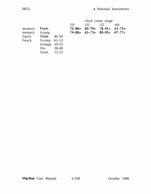
IBCL o National Instruments
clock count rangei16 r32 i32 r64
memory fcom. 72-86+ 60-70+ 78-91+ 65-75+memory fcomp. 74-88+ 63-73+ 80-93+ 67-77+fstack fcom. 40-50fstack fcomp. 45-52
fcompp. 45-55ftst. 38-48fxam. 12-23
MacBus User Manual 3-108 October 1986

o National Instruments IBCL
Constants
Push the specified constant onto the fstack.
fldz.fldl.fldpi.fld12t.fldl2e.fldlg2.fldln2.
zeroone
Eg base 2 of 10log base 2 of elog base 10 of 2log base e of 2
Arithmetic
fadd.fsub.fmul.fdiv.
fadd”.fsub”.fmul”.fdiv”.
faddp.fsubp.fmulp.fdivp.
clock count11-1715-2116-2216-2215-2118-2417-23
fsubr.
fdivr.
fsubr”.
fdivr”.
fsubrp.
fdivrp.
Add, subtract, multiply, or divide the number on top of the fstackand the memory/fstack operand. The suffix determines thedestination, order of operands, and whether or not to pop the topof the stack.
noneII
P
rI”rP
Subtract from/divide into number on top of fstack.result returned in top of fstackresult returned to mem/fstack operandresult returned to mem/fstack operand
fstack popped
Subtract from/divide into mem/fstack operandresult returned in top of fstackresult returned to mem/fstack operandresult returned to mem/fstack operand
and fstack popped
October 1986 3-109 MacBus User Manual

IBCL o National Instruments
memorymemorymemorymemoryfstackfstackfsteckfstack
fadd--.fsub--.fnwl--.fdiv--.fadd--.fsub--.flmll--.fdiv--.
clock count rangestack i16 r32 i32 t-64
102-137+ 90-120+ 108-143+ 95-125+102-137+ 90-120+ 108-143+ 95-125+124-138+ IIO-125+ 130-144+ 112-168+224-238+ 215-225+ 230-243+ 220-230+
70-10070-10090-145193-203
The following words use the top one or two numbers on thefstack. The result replaces the top number (x), but any secondnumber (y) remains on the stack unchanged.
clock count
fsqrt.
fscale.
fmdint.fxtract.
fabs.fchs.fprem.
180-186 Replace top number with its square root.-0 <= x <= +infinity
32-38 Scale top number by second.i.e., Add second (rounded toward zero toan integer) to the exponent of the first.-2**15 <= y <= 2**15, y integer
16-50 Round top number to integer.27-55 Replace top number with its exponent,
then push significand onto fstack.(an fscale. at this point would putthe number back together, except thata copy of the exponent would remain.)
10-17 Absolute value of top number.10-17 Change sign of top number.15-190 Partial remainder of top/second.
fprem. is usually used to reduce the argument of a cyclic functionto its fundamental range. (to reduce an angle in radians to therange of 0.0 through pi/4) To allow more rapid response tosystem interrupts, the maximum clock count of this instruction hasbeen kept low by limiting the range reduction for one step to2**64. If the top number was ( 33.9 * 2**64 * pi/4 ) and the
MacBus User Manual 3-110 October 1986

o National Instruments IBCL
second was pi/4, one execution would leave ( 33.9 * pi/4 ), whichis still not in the range of the fptan. function. A secondexecution would leave the desired result, ( .9 * pi/4 ). Bit c2 ofthe status word will be set if the operation must be repeated.
The three lowest order bits of the quotient are returned in statusword bits CO, c3, and cl, where cl is the least significant bit andCO the most significant. c3 occupies bit 14 of the status word,while c2 through CO occupy bits 10, 9 and 8. If you store thestatus word out to memory to check these bits, remember to usean fwait. after the store and before trying to load the status wordinto an NEC V50 register or otherwise attempting to use it.
October 1986 3-111 MacBus User Manual

IBCL o National Instruments
Transcendental
The transcendental instructions also use the top one or twonumbers on the fstack. x represents the number on top of thefstack, and y the number under it.
In all cases, the arguments are destroyed and only the results arereturned on the fstack.
ALL ARGUMENTS MUST BE VALID, NORMALIZED, ANDIN RANGE.
fptan.
fpatan.
f2xml.
fyl2x.
clocks_____30-540 Tangent. Angle (x) must be in radians
with 0 < x < pi/4. This function does notreally return the tangent, but the length of theopposite and adjacent side of a triangle withradius about 1.5. The length of the adjacentside is stored on top so the tangent could becalculated with: 1 fdivrp.
250-800 Arctangent. Arguments are lengths of theopposite and adjacent sides as returned byfptan. 0 < y(opposite) < x(adjacent) < infinity
310-630 Exponential. (2 ** x) - 1x must be between 0 and 0.5 inclusive.Offsetting the result by minus one preservesprecision when x is very near zero and theresult would be very near one. To calculateother exponents, use the relation x**y =2**(y * LOG2(x))
Y * log2( x ) 0 < x < +infinity900-l 100 -infinity < y < +infinity
Note: Neither x nor y can be infinite.
MacBus User Manual 3-112 October 1986

o National Instruments IBCL
fyl2xpl. y * log2( x+1 ) 0 <= x <= I-sqrt(0.5)700- 1000 -infinity < Y < +infinity
The inverse of f2xml.
Processor Control
i-hit.
fnop.
fwait.
fldcw.
fstcw.
fstsw.
feni.
fdisi.
2-8
IO-16
3+5n
7-14+
12-18+
12-18+
2-8
2-8
Initialize NEC 72 19 1Control word:projective infinity, round to nearest, 64 bits,interrupts disabled, all exceptions maskedStatus word:not busy, empty stack, no interrupt, noexceptionsTag word:all tags 11 for empty registerData registers unchanged
No operation.
Wait until NEC 72191 has completed instruction.
Load control word into NEC 72 191. (2 bytes)memory fldcw.
Store NEC 72191 control word into memory.(2 bytes)memory fstcw.
Store NEC 72191 status word into memory.(2 bytes)memory fstsw.
Enable interrupts. Clear interrupt enablemask bit in Control word.
Disable interrupts. Set interrupt enablemask bit in Control word.
October 1986 3-113 MacBus User Manual

IBCL e National Instruments
fclex. 2-8
flncstp. 6-12
Clear exception, interrupt and busy flags.
Increment fstack pointer. This makes aregister within the fstack the temporarytop of fstack. If you pop numbers whileat this temporary top of fstack, youcould leave empty registers within yourfstack. Use with care.
fdecstp.
ffree.
6-12 Decrement fstack pointer.
9-16 Mark indicated register empty.fstack# ffree.
fstenv. 40-50+ Store environment.Control word, status word, tag word, instructionpointer, operand pointer. (14 bytes)
memory fstenv.
fldenv. 35-45+ Load environment.memory fldenv.
fsave. Save complete NEC 72191 state in 94 byte area197-207+ with environment at beginning followed by
data registers.memory fsave.
frstor. Restore NEC 72191 state.197-207+ memory fsave.
MacBus User Manual 3-114 October 1986

o National Instruments IBCL
SEGMENT MANAGl!lMENT
IBCL provides two mechanisms for manipulating the full onemegabyte address range of the NEC V50. This section documentsthe segment management system which is designed for use prior tocompilation of your program. The heap manager, which isdesigned for use during execution of your program, is discussed inthe section “HEAP MANAGEMENT WORDS.”
IBCL reserves areas of memory for various purposes. Forinstance, IBCL reserves a large area for definitions of new wordsyou define. In IBCL terminology we say that the definitionsegment is not completely full. It does, however, have a defaultsize limit that is less than 64K. If you try to compile a largeprogram you may run out of dictionary space.
The IBCL words discussed in this section allow you to enlargeIBCL’s reserved areas prior to compiling your program. Includethe necessary segment management word sequence at thebeginning of your program.
These words conflict with the heap manager. Once you haveinitialized the heap, you may no longer use segment managementwords.
Relocation Tools
The basic segment relocation tool is copy-seg. A new segment forthe destination must be created first unless an old one can bereused. The size of the destination segment must be sufficient tohold the portion of the source segment below its working end.The destination segment may be larger or smaller than the source.To create a new segment and copy an old one into it, type:
size-of-new-segment segment name-of-new-segmentname-of-source-segment name-of-new-segment copy-seg
Another word will automatically allocate space for a new segment,move the contents of the old segment to it, and reuse the oldsegment descriptor and name for the new location. The descriptor
October 1986 3-115 MacBus User Manual
IBCL o National Instruments
is relinked to maintain a sequential list corresponding to thephysical memory. (First descriptor in the list is for the topsegment, last descriptor is for the lowest.) The space occupied bythe segment is added to the space allocated to the segment belowit. This word is primarily used by the special system segmentmove words.
new-size segment-descriptor move-seg
The new size is left on the stack and the segment descriptor isreplaced by the new first paragraph number.
System segments cannot be summarily moved. Other actions musttake place to maintain continuity of control. These segmentsinclude the definition list segment lists, the stack segment stacks,and all vocabulary segments including ibcls. The code segmentcodes is never moved. Its size may be increased up to 64K bytesby moving the segments above it higher.
Additional definition list segments may be created by typing:
size-of-new-list-segment make-list name-of-new-segment
Control may be transferred to an alternate definition list segmentby typing:
alternate-segment-descriptor use-list
Alternate list segments should only be created from the originalsystem list segment lists. When in the alternate segment, itsdescriptor will use the name lists. Return to the system listsegment is accomplished by again typing:
alternate-segment-descriptor use-list
The first action on entering an alternate list segment should be tocreate a new vocabulary for words created in it. Words from asingle vocabulary should always refer to a single definition listsegment. The task and forget-task pair will not work if used
MacBus User Manual 3-116 October 1986

Q National Instruments IBCL
across multiple list segments.
The following words are used to move system segments and altertheir size:
new-size new-voc (moves context vocabulary segment)new-size new-stacknew-size new-list
In each case the new size is checked against the working end ofthe segment and the operation aborts if it is too small. Thecontents of the old segment are moved to the new segment at thestart of free memory, and the old segment descriptor and nameare reused. The descriptor is relinked to maintain a sequential listcorresponding to the physical memory. The first descriptor in thelist is for the highest segment, last descriptor is for the lowest.The space formerly occupied by the segment is added to the spaceallocated to the segment below it.
Although segments may be moved at any time, it is advisable toplan each move carefully. Careless moving can leave gaps in thememory map that are unreachable by the segment managementutilities. More general memory management operations areprovided by the heap manager.
GPIB Control Words
IBCL provides a complete set of words for manipulation of theIEEE-488 (GPIB) bus. This section documents the IBCL GPIBword set. For a complete explanation of GPIB operations, seeAPPENDIX B.
IBCL has two types of words that manipulate the GPIB: devicelevel words and MacBus GPIB port level words. When you usedevice level words IBCL automatically computes and sends therequired command strings over the GPIB. IBCL maintains a tableof configuration information for each device. This informationdefines the characteristics of a particular device, including itsGPIB address, a time limit for data transfers, and any end-of-string modes.
February 1987 3-117 MacBus User Manual

IBCL o National Instruments
When performing I/O operations, IBCL takes the device’s GPIBaddress from the appropriate configuration table and its own GPIBaddress from the MacBus interface configuration table and sendsthese out as GPIB command bytes. The configuration tables maybe changed with IBCL words documented later in this section.
To perform device level operations, MacBus must be CIC.
The following is a description of each GPIB-related IBCL word.
GPIB Status Variables
Some of the GPIB words documented so far use global variables toreflect their status. This technique allows easy access to operationresults without cluttering up IBCL’s stack. The global IBCLvariables are:
ibret ( -- a)iberr ( -- a)ibcnt ( -- a)ibppr ( -- a)ibspr ( -- a)
contains return value from last operation.contains error status of last operation.contains byte count of last transfer.contains response from last parallel pollcontains response from last serial poll.
Associating Names with GPIB Devices
Device level IBCL words require a device number as a stackparameter. A device’s configurations table stores its name,however, IBCL lets you use this name in device calls instead ofhaving to remember the device number. The IBCL word ibfindscans the device table for a name and creates an IBCL constant ofthis name using the device number as the value. For instance, ifyou have used the IBCONF utility to give device 3 the name‘plotter’, you may issue the following ibfind call:
ibfind plotter
Now you may use the word plotter anywhere in an IBCL programand the result will be the same as if you had used the number 3instead.
MacBus User Manual 3-118 February 1987

Q National Instruments IBCL
Note that ibfind MAY NOT BE COMPILED INTO AN IBCLWORD! You MUST issue any ibfind commands outside of colondefinitions. Once device names are defined, they may be usedwithin colon definitions.
Device Level Words
The following pages describe the device level words.
February 1987 3-119 MacBus User Manual

CLR (device) CLR
NAMEclr - send selected device clear (SDC)
SYNOPSISd clr
DESCRIPTIONd is a device number or device name used in an ibfind call.
clr sends the message selected device clear (SDC). SDCreinitializes all device functions. clr sends the followingcommands:
- Unlisten (UNL)- Listen address of the device- Secondary address of the device if applicable- Selected Device Clear (SDC)- Unlisten (UNL)
EXAMPLE
1. To clear device plotter:
plotter clr
MacBus User Manual 3-120 February 1987

LLO (device) LLO
NAME110 - place all devices in local lockout state
SYNOPSISd 110
DESCRIPTIONd is a device number or device name used in an ibflnd call.
110 sends the message LLO which places all devices in thelocal lockout state. This usually inhibits recognition offront panel input.
Ilo sends the following command:
- Local Lockout (LLO)
EXAMPLE
1. To place device plotter in local lockout state:
plot ter Llo
SEE ALSOlot.
February 1987 3-121 MacBus User Manual

LOC (device) LOC
NAMElot - go to local mode
SYNOPSISd lot
DESCRIPTIONd is a device number or device name used in an iblind call.
lot is used to move devices temporarily from a remoteprogram mode to a local mode. A device enters remotemode when the REN line is asserted and the device detectsits listen address.
lot places the indicated device in local mode by sendingthe command sequence:
- Unlisten (UNL)- Listen address of the device- Secondary address of the device if applicable- Go To Local (GTL)- Unlisten (UNL)
EXAMPLE
1. To return device plotter to local state:
plot ter Lot
SEE ALSO110.
MacBus User Manual 3-122 February 1987

ONL (device) ONL
NAMEon1 - place device online or offline
SYNOPSISd f on1
DESCRIPTIONd is a device number or device name used in an ibflnd call.
f is a true/false value indicating online/offline.
on1 reinitializes all software as though bringing the deviceonline for the first time.
Call on1 with f non-zero to reset a device software to itspower-on state. Call on1 with f zero only when finishedwith a device.
EXAMPLE
1. To disable device plotter:
plotter 0 on1
SEE ALSOibfind.
February 1987 3-123 MacBus User Manual

PCT (device) PCT
NAMEpet - pass control
SYNOPSISd pet
DESCRIPTIONd is a device number or device name used in an ibfind call.
pet passes Controller-In-Charge (CIC) authority to thespecified device. The MacBus GPIB port automaticallygoes to an idle state. The function assumes that the devicehas Controller capability.
pet sends the following commands.
- Talk address of the device- Secondary address of the device, if applicable- Take Control (TCT)
EXAMPLE
1. To pass control to device pcxt:
MacBus User Manual 3-124 February 1987
PPC (device) PPC
NAMEppc - parallel poll configure
SYNOPSISd v PPC
DESCRIPTIONd is a device number or device name used in an ibfind call.
v is a valid parallel poll enable/disable command.
ppc enables or disables the device from responding toparallel polls.
ppc sends the following commands:
- Unlisten (UNL)- Listen address of the device- Secondary address of the device, if applicable- Parallel Poll Configure (PPC)- Parallel Poll Enable (PPE) or Disable (PPD)- Unlisten (UNL)
Each of the 16 PPE messages specifies the GPIB data line(DIOl through D108) and sense (one or zero) that thedevice must use when responding to the Identify (IDY)message during a parallel poll. The assigned message isinterpreted by the device along with the current value ofthe individual status (ist) bit to determine if the selectedline is driven true or false. For example, if PPE=Ox64,DIOS is driven true if ist=O and false if ist=l. And ifPPE=Ox68, DIOl is driven true if ist=l and false if ist=O.Any PPD message or zero value cancels the PPE messagein effect.
Which PPE and PPD messages are sent and the meaning ofa particular parallel poll response are all system dependentprotocol matters to be determined by the user.
February 1987 3-125 MacBus User Manual
PPC (device) PPC
EXAMPLES
1. To configure device dvm to respond to a parallel pollby sending data line D103 true if IST=O:
dm 62 ppc
2. To configure device dvm to respond to a parallel pollby sending data line DIOl true if IST= 1:
dm 68 ppc
3. To cancel the parallel poll configuration of devicedvm:
SEE ALSOrpp.
MacBus User Manual 3-126 February 1987

(device) RD
NAMErd - read data from GPIB
SYNOPSISd buf cnt rd
DESCRIPTIONd is a device number or device name used in an ibfind call.
buf is the long address of the buffer to use (buf might havebeen created using allot).
cnt specifies the number of bytes to read from the GPIB.
rd reads cnt bytes of data from a GPIB device. Thefollowing steps are performed:
1. The device is addressed to talk and the MacBus GPIBport to listen, if not already addressed to do so.
2. The MacBus GPIB port reads the data from thedevice.
3. Attention is reasserted.
When rd returns, ibcnt is the actual number of data bytesread from the device; and iberr is the first error detectedif iberr is non-zero.
rd operation terminates on any of the following events:
- When cnt bytes have been read- Error is detected- Time limit is exceeded- END message is detected- eos character is detected (if this option is enabled)
After termination, ibcnt contains the number of bytes read.
October 1986 3-127 MacBus User Manual

(device) RD
EXAMPLES
1. To read hex 56 bytes of data from device tape:
tape buf 56 rd
MacBus User Manual 3-128 October 1986

RPP (device) RPP
NAMErpp - conduct a parallel poll
SYNOPSISd rpp
DESCRIPTIONd is a device number or device name used in an ibfind call.
rpp conducts a parallel poll of previously configureddevices by sending the IDY message (ATN and EOI bothasserted). If ibret contains a non-zero value uponcompletion, ibrpp contains a valid response.
EXAMPLE
1. To remotely configure device lcrmtr to respondpositively on D103 if its individual status bit is 1, andthen parallel poll all configured device:
lcrmtr 6A ppclcrmtr rpp
SEE ALSOPPC.
October 1986 3-129 MacBus User Manual

RSP (device) RSP
NAMEw - conduct a serial poll
SYNOPSISd rsp
DESCRIPTIONd is a device number or device name used in an ibthd call.
rsp is used to serially poll one device and obtain its statusbyte or to obtain a previously stored status byte. If the0x40 bit of the response is set, the status response ispositive, i.e., the device is requesting service.
If automatic serial polling is enabled (defaultconfiguration), devices are polled the instant they requestservice. Positive responses are saved in a queue. If adevice has been polled, the RQS bit of that device’s statusword is set, and in this case a call to rsp returns thepreviously acquired status byte. If the RQS bit of thestatus word is not set when rsp is called, the device isserially polled. Upon completion, if ibret contains a non-zero value, ibspr contains a valid serial poll response.
The interpretation of the response in ibspr, other than theRQS bit, is device-specific. For example, the polleddevice might set a particular bit in the response byte toindicate that it has data to transfer, and another bit toindicate a need for reprogramming. Consult themanufacturer’s documentation for the device forinterpretation of the response byte.
MacBus User Manual 3-130 October 1986

RSP (device) RSP
EXAMPLE
1. To obtain the Serial Poll response byte from devicetape:
tape rsp
SEE ALSOwait, wrqs.
February 1987 3-131 MacBus User Manual
(device) TRG
NAMEtrg - Send device trigger
SYNOPSISd trg
DESCRIPTIONd is a device number or device name used in an ibflnd call.
trg addresses and triggers the specified device, thenunaddresses all devices on the GPIB.
trg sends the following commands:
- Unlisten (UNL)- Listen address of the device- Secondary address of the device, if applicable- Group Execute Trigger (GET)- Unlisten (UNL)
The response to a trigger is device dependent.
EXAMPLE
1. To trigger device analyz:
analyz trg
MacBus User Manual 3-132 February 1987

WAIT (device) WAIT
NAMEwait - wait for selected events
SYNOPSISd mask wait
DESCRIPTIONd is a device number or device name used in an ibflnd call.
The mask bit is set to wait for the corresponding event tooccur.
wait is used to monitor the events selected in mask and todelay processing until any of them occur. These eventsand bit assignments are shown below:
Device Wait Mask LayoutMnemonic Bit Hex Description
Pos ValTIM0 14 4000 Time limit exceededEND 13 2000 END detected
RQS 11 800 Device requestingservice
Disabling timeouts should be done only when it is certainthe selected event will occur. wait always returns whenthe time limit is exceeded regardless of whether the TIM0bit is specified. To disable timeouts, use the configurationcontrol words (described later in this section)to set the time limit to zero.
EXAMPLES
1. To wait for zero:
logger 0 wait
2. To wait for device logger to request service or timeout:
logger 4800 wait
February 1987 3-133 MacBus User Manual

WAIT (device) WAIT
3. To wait indefinitely for device logger to requestservice:
0 logger d_tmo setdlogger 800 wait
SEE ALSOrsp, wrqs.
MacBus User Manual 3-134 February 1987

WRQS (device) WRQS
NAMEwrqs - wait for specific status byte
SYNOPSISd mask val wrqs
DESCRIPTIONd is a device number or device name used in an ibfind call.
mask defines the specific status bits of interest.
val defines the desired bit configuration.
wrqs will wait for a device to request service with a statusbyte that matches the mask and value. The serial pollqueue is first examined to see if a match is found.
A match is made if a status byte, stb, is received such that:
(stb & mask) == value
This technique allows waiting for specific bits in a statusbyte. An exact match of the value is always required.
EXAMPLES
1. To wait for device rx3 to request service with the bytehex 45:
rx3 FF 45 wrqs
2. To wait for device rx3 to request service with any bytewith either bit 2 or bit 3 asserted:
rx3 OC OC wrqs
SEE ALSOrsp, wait.
February 1987 3-135 MacBus User Manual

(device) WRT
NAMEwrt - write data to GPIB
SYNOPSISd buf cnt wrt
DESCRIPTIONd is a device number or device name used in an ibiind call.
buf contains the data to be sent over the GPIB (buf mighthave been allocated using allot).
cnt specifies the number of bytes to be sent over the GPIB.
wrt writes cnt bytes of data to a GPIB device.
The following steps are performed:
1. The device is addressed to listen and the MacBusGPIB port to talk, if not already addressed to do so.
2. The MacBus GPIB port writes the data to the device.
3. Attention is reasserted.
When wrt returns, ibcnt is the actual number of data byteswritten to the device; and iberr is the first error detected ifiberr is non-zero.
wrt terminates on any of the following events:
- When cnt bytes have been written- Error is detected- Time limit is exceeded
After termination, ibcnt contains the number of byteswritten.
The double quote (‘I) places the text, up to the closingquote, in memory.
The double quote word leaves the long address and stringlength on the stack and is thus ideal for use with wrt. Forinstance, “abc” leaves the long address of the string and a
MacBus User Manual 3-136 February 1987

WRT (device) WRT
count of 3 on the stack.
EXAMPLES
1. To write 10 bytes of instructions to device dvm:
dvm M F3RlX5PZGO" wrt
February 1987 3-137 MacBus User Manual

IBCL o National Instruments
MacBus GPIB Port Level Words
MacBus GPIB Port level words are used to manipulate the MacBusGPIB port directly. These words are used in situations thatrequire greater flexibility than the device functions provide.
Such situations include:
- Anytime MacBus is not CIC.
- A Group Execute Trigger (GET) involving more than onedevice.
- A data transfer between two devices without MacBusparticipating.
- Waiting for any device to request service (see wait).
To use these words, you must be familiar with GPIB protocol. Itis your responsibility to perform all addressing and unaddressingof the GPIB.
MacBus User Manual 3-138 February 1987

BCAC (GPIB port) BCAC
NAMEbcac - become active controller
SYNOPSISv bcac
DESCRIPTION
If v is non-zero, MacBus takes control synchronously withrespect to data transfer operations; otherwise, MacBustakes control immediately (and possibly asynchronously).
It is generally not necessary to use the bcac word. Wordssuch as bcmd and brpp, which require that MacBus takecontrol, do so automatically.
To take control synchronously, MacBus waits beforeasserting the ATN signal so that data being transferred onthe GPIB will not be corrupted. If a data handshake is inprogress, the take control action is postponed until thehandshake is complete; if a handshake is not in progress,the take control action is done immediately. Synchronoustake control is not guaranteed if an brd or bwrt operationcompleted with a timeout or error.
Asynchronous take control should be used in situationswhere it appears to be impossible to gain controlsynchronously (e.g., after a timeout error).
The ECIC error results if MacBus is not CIC.
EXAMPLES
1. To take control immediately without regard to anydata handshake in progress:
1 bcac
February 1987 3-139 MacBus User Manual

BCAC (GPIB port) BCAC
2. To take control synchronously and assert ATNfollowing a read operation:
1 bcac
MacBus User Manual 3-140 February 1987

BCMD (GPIB port) BCMD
NAMEbcmd - send command message to GPIB
SYNOPSISbuf cnt bcmd
DESCRIPTIONbuf is the long address of a buffer containing thecommands to be sent over the GPIB.
cnt specifies the number of bytes to be sent over the GPIB.
bcmd is used to transmit interface messages (commands)over the GPIB. These commands include device talk andlisten addresses, secondary addresses, serial and parallelpoll configuration messages, and device clear and triggerinstructions.
bcmd is NOT used to transmit programming instructions todevices; programming instructions and other devicedependent information are transmitted with brd and bwrt.
bcmd terminates on any of the following events:
- All commands are successfully transferred- Error is detected- Time limit is exceeded- Take Control (TCT) command is sent- Interface Clear (IFC) message is received from the
System Controller (not MacBus)
After termination, the ibcnt variable contains the numberof command bytes sent.
An ECIC error results if the MacBus GPIB port is not CIC.If the MacBus GPIB port is not Active Controller, itasserts ATN prior to sending the command bytes. TheMacBus GPIB port remains Active Controller afterward.
February 1987 3-141 MacBus User Manual
BCMD (GPIB port) BCMD
EXAMPLES
In the following examples, GPIB commands and addressesare coded as printable ASCII characters. When the hexvalues to be sent over the GPIB correspond to printableASCII characters, this is the simplest means of specifyingthe values. APPENDIX A contains conversions of hexvalues to ASCII characters.
1. To unaddress all Listeners with the Unlisten command(ASCII ?) and address a Talker at 0x46 (ASCII F) anda Listener at 0x31 (ASCII 1):
” ?Fl" bcmd
2. Same as Example 1 except the Listener has a secondaryaddress of Ox6E (ASCII n):
MacBus User Manual 3-142 February 1987

BGTS (GPIB port) BGTS
NAMEbgts - go from active controller to standby
SYNOPSISv bgts
DESCRIPTION
v is the type of go-to-standby.
bgts causes MacBus to go to the Controller Standby stateand to unassert the ATN signal if it is the ActiveController. bgts permits GPIB devices to transfer datawithout MacBus being a party to the transfer.
It is generally not necessary to use bgts. Functions such asbrd and bwrt, which require that MacBus go to standby, doso automatically.
If v is non-zero, MacBus shadows data transfer handshakesas an Acceptor, and when the END message is detected,MacBus enters a Not Ready For Data (NRFD) handshakeholdoff state on the GPIB. If v is zero, no shadowhandshake or holdoff is done.
If the shadow handshake option is activated, MacBusparticipates in data handshake as an Acceptor withoutactually reading the data. It monitors the transfers for theEND message and holds off subsequent transfers. Thismechanism allows MacBus to take control synchronously ona subsequent operation such as bcmd or brpp. 1 bgtsshould always be followed by a wait for END (Example 2).
The ECIC error results if MacBus is not CIC.
February 1987 3-143 MacBus User Manual

BGTS (GPIB port) BGTS
EXAMPLES
1. To turn the ATN line off
0 bgts
2. To turn the ATN line off with bgts after unaddressingall listeners with the Unlisten (ASCII ?) command,addressing a talker at 0x46 (ASCII F), and addressing alistener at 0x31 (ASCII 1) to allow the talker to senddata messages:
" ?Fl" bcmd1 bgts6000 buait
SEE ALSObcac, bcmd, bwait.
MacBus User Manual 3-144 February 1987
BIST (GPIB port) BIST
NAMEbist - set or clear individual status bit (IST)
SYNOPSISv bist
DESCRIPTIONv is the sense of the IST bit.
If v is non-zero, the individual status bit is set. If v iszero, the bit is cleared.
bist is used when MacBus participates in a parallel pollthat is conducted by another device that is the ActiveController. The Active Controller conducts a parallel pollby asserting the EOI and ATN signals which send theIdentify (IDY) message. While this message is active, eachdevice that has been configured to participate in the pollresponds by asserting a predetermined GPIB data lineeither true or false, depending on the value of its local ISTbit. MacBus, for example, can be assigned to drive theD103 data line true if IST=l and false if IST=O;conversely, it can be assigned to drive D103 true if IST=Oand false if IST= 1.
The relationship between the value of IST, the line that isdriven, and the sense at which the line is driven isdetermined by the Parallel Poll Enable (PPE) message ineffect for each device. MacBus is capable of receiving thismessage either locally, via bppc, or remotely, via acommand from the Active Controller. Once the PPEmessage is executed, bist changes the sense at which theline is driven during the parallel poll, and in this fashionMacBus can convey a one-bit, device dependent messageto the Controller.
October 1986 3-145 MacBus User Manual

BIST (GPIB port)
EXAMPLES
1. To set the individual status bit:
1 bist
2. To clear the individual status bit:
0 bist
SEE ALSObm, brw.
MacBus User Manual 3-146
BIST
October 1986

BLOC (GPIB port) BLOC
NAMEbloc - go to local mode
SYNOPSISbloc
DESCRIPTIONThe MacBus GPIB port is placed in a local state bysending the local message Return To Local (rtl), providedit is not locked in remote mode. bloc is used to simulate afront panel Return-To-Local switch when the computer isused to simulate an instrument.
EXAMPLE
1. To return the MacBus GPIB port to local state:
bloc
SEE ALSObsre.
February 1987 3-147 MacBus User Manual

BONL (GPIB port) BONL
NAMEbon1 - place MacBus GPIB port online or offline
SYNOPSISv bon1
DESCRIPTIONIf v is non-zero, the MacBus GPIB port is enabled foroperation (i.e., online). If v is zero, it is held in a reset,disabled mode (offline).
Taking the MacBus GPIB port offline may be thought of asdisconnecting its GPIB cable from the other devices.
bon1 can also be used to restore the default configurationsettings of a MacBus GPIB port. Calling bon1 with vnon-zero when the device or MacBus GPIB port is alreadyonline simply has the effect of restoring all configurationsettings to their defaults.
EXAMPLES
1. To reset the configuration settings to their defaults:
1 bon1
2. To disable MacBus GPIB port:
0 bon1
SEE ALSOibfind.
MacBus User Manual 3-148 February 1987

BPPC (GPIB port) BPPC
NAMEbppc - parallel poll configure
SYNOPSISv bppc
DESCRIPTIONv is a valid parallel poll enable/disable command.
The MacBus GPIB port itself is programmed to respond toa parallel poll by setting its local poll enable (lpe) messageto the value of v.
Each of the 16 PPE messages specifies the GPIB data line(DIOI through D108) and sense (one or zero) that thedevice must use when responding to the Identify (IDY)message during a parallel poll. The assigned message isinterpreted by the device along with the current value ofthe individual status (ist) bit to determine if the selectedline is driven true or false. For example, if PPE=Ox64,D105 is driven true if ist=O and false if ist=l. And ifPPE=Ox68, DIOI is driven true if ist=l and false if ist=O.Any PPD message or zero value cancels the PPE messagein effect.
Which PPE and PPD messages are sent and the meaning ofa particular parallel poll response are all system dependentprotocol matters to be determined by the user.
The 16 valid PPE messages and the 16 valid PPD messagesare found in APPENDIX A.
EXAMPLES
1. To cancel the parallel poll configuration of MacBus:
70 bppc
2. To configure MacBus GPIB port to respond to aparallel poll by sending data line DIO8 true if IST=O:
February 1987 3-149 MacBus User Manual

BPPC
SEE ALSObcmd, bist.
MacBus User Manual
(GPIB port)
3-150
BPPC
February 1987

(GPIB port) BRD
NAMEbrd - read characters from GPIB
SYNOPSISbuf cnt brd
DESCRIPTIONbuf is the long address of the buffer to use.
cnt specifies the number of bytes to read from the GPIB.
brd reads cut bytes of data from a GPIB device.
brd attempts to read from a GPIB device that is assumedto already be properly initialized and addressed.
If the MacBus GPIB port is CIC, bcmd must be calledprior to brd to address a device to talk and the MacBusGPIB port to listen. If the MacBus GPIB port is not CIC,the device on the GPIB that is the CIC must perform theaddressing.
If the MacBus GPIB port is Active Controller, the MacBusGPIB port is first placed in Standby Controller state (ATNoff) and remains there after the read operation iscompleted.
An EADR error results if the MacBus GPIB port is CICbut has not been addressed to listen with bcmd. An EABOerror results if the MacBus GPIB port is not CIC and isnot addressed to listen within the time limit. An EABOerror also results if the device that is to talk is notaddressed and/or the operation does not complete forwhatever reason within the time limit.
brd operation terminates on any of the following events:
- When cnt bytes have been read- Error is detected- Time limit is exceeded- END message is detected- eos character is detected (if this option is enabled)
October 1986 3-151 MacBus User Manual

BRD (GPIB port) BRD
- Device Clear (DCL) or Selected Device Clear (SDC)command is received from another device which is CIC
After termination, ibcnt contains the number of bytes read.A short count can occur on any of the above events butthe first.
EXAMPLE
1. To read 56 bytes of data from a device at talk addressOx4C (ASCII L) and then unaddress it (the MacBusGPIB port at listen address is 0x20 or ASCII blank):
” ? L ” bcmd ( address talker and listener )twf 56 brd ( read data )II ?” bcmd ( unaddress talker and listener )
SEE ALSObcmd, beos.
MacBus User Manual 3-152 October 1986

(GPIB port) BRPP
NAMEbrpp - conduct a parallel poll
SYNOPSISbrpp
DESCRIPTIONbrpp conducts a parallel poll of previously configureddevices by sending the IDY message (ATN and EOI bothasserted).
When done, if ibret contains a non-zero value, ibpprcontains a valid poll response.
An ECIC error results if MacBus is not CIC. If MacBus isStandby Controller, it takes control and asserts ATN(becomes Active) prior to polling. It remains ActiveController afterward.
EXAMPLE
1. To remotely configure a device at listen address 0x23to respond positively on D103 if its individual statusbit is I, and then parallel poll all configured devices:
23 cmd c!L5 cmdl+c!L68 cmd 2 + C!L3F cmd 3 + c! 1cmd4bcmd
brw
SEE ALSObcmd, bist, bppc.
( listen address )( parallel poll configure )( parallel poll enable )( unlisten )( send comsnd string )( response in ibppr )
October 1986 3-153 MacBus User Manual

(GPIB port) BRSC
NAMEbrsc - request or release system control (SC)
SYNOPSISv brsc
DESCRIPTIONv specifies request or release system control.
If v is non-zero, functions requiring System Controllercapability are subsequently allowed. If v is zero, functionsrequiring System Controller capability are disallowed.
brsc is used to enable or disable the capability of MacBusto send the Interface Clear (IFC) and Remote Enable(REN) messages to GPIB devices using the bsic and bsrefunctions. The MacBus GPIB port must not be SystemController to respond to Interface Clear sent by anotherController.
In most applications, MacBus will always be the SystemController. In other applications, MacBus will never bethe System Controller. In either case, brsc is used only ifthe Macintosh Plus is not going to be System Controller forthe duration of the program execution. While the IEEE-488 standard does not specifically allow schemes in whichSystem Control can be passed dynamically from one deviceto another, brsc would be used in such a scheme.
EXAMPLE
1. To request to be System Controller if the MacBusGPIB port is not currently so designated:
1 brsc
MacBus User Manual 3-154 October 1986

BRSV (GPIB port) BRSV
NAMEbrsv - request service and/or set serial poll status byte
SYNOPSISv brsv
DESCRIPTIONv specifies the serial poll response byte.
If the 0x40 bit is set in v, MacBus additionally requestsservice from the Controller by asserting the GPIB SRQline.
brsv is used to request service from the Controller usingthe Service Request (SRQ) signal and to provide a systemdependent status byte when the Controller serially pollsMacBus.
It is not an error to call brsv when MacBus is CIC,although this usage makes sense only if control will bepassed later to another device. In this case, the callupdates the status byte, but the SRQ signal is asserted onlyif the 0x40 bit is set and only when control is passed.
EXAMPLES
1. To set the Serial Poll status byte to 0x41, whichsimultaneously requests service from an external CIC:
41 brsv
2. To stop requesting service (unassert SRQ):
0 brsv
3. To change the status byte to 1 without requestingservice:
1 brsv
February 1987 3-155 MacBus User Manual

BSIC (GPIB port) BSIC
NAMEbsic - send interface clear (IFC)
SYNOPSISbsic
DESCRIPTIONbsic causes MacBus to assert the IFC signal for at least 100ms, provided MacBus has System Controller authority.This action initializes the GPIB and makes the MacBusGPIB port CIC. bsic is generally used when you want tobecome CIC or clear a bus fault condition.
The IFC signal is supposed to reset only the GPIBinterface functions of bus devices and is not intended toreset internal device functions. Device functions are resewith the Device Clear (DCL) and Selected Device Clear(SDC) commands. To determine the effect of thesemessages, consult the device documentation.
EXAMPLE
1. To initialize the GPIB and become CIC at thebeginning of a program:
SEE ALSObrsc.
MacBus User Manual
t
3-156 February 1987

BSRE (GPIB port) BSRE
NAMEbsre - set or clear Remote Enable (REN)
SYNOPSISv bsre
DESCRIPTIONv specifies set or clear.
bsre turns the REN signal on and off. If v is non-zero, theRemote Enable (REN) signal is asserted. If v is zero, thesignal is unasserted. REN is used by devices to selectbetween local and remote modes of operation. RENenables the remote mode. A device does not actually enterremote mode until it receives its listen address.
The ESAC error occurs if MacBus is not System Controller.
EXAMPLES
1. To place a device at listen address 0x23 (ASCII #) inremote mode with local ability to return to local mode:
1 bsre" #" bcmd
( set REN to true )( LAD 1
2. To exclude the local ability of the device to return tolocal mode, send the Local Lockout command (0x1 I),or include it in the command string in Example 1:
11 buf c!L ( send LLO )buflbcmd
or
1 bsre ( REN true 1ascii # buf c! 1 ( LAD LLO )11 buf 1 + c!lbuf2bcn-d
October 1986 3-157 MacBus User Manual

BSRE (GPIB port)
3. To return all devices to local mode:
0 bsre
SEE ALSObrsc, bsic.
( set REN to false )
MacBus User Manual 3-158
BSRE
October 1986

BWAIT (GPIB port) BWAIT
NAMEbwait - wait for selected events
SYNOPSISmask bwait
DESCRIPTIONThe mask bit is set to wait for the corresponding event tooccur.
bwait is used to monitor the events selected in mask and todelay processing until any of them occur. These eventsand bit assignments are shown below:
Mnemonic
TIM0ENDSRQILOKREMCICTACSLACSDTASDCAS
Board Wait Mask LayoutBit 1 Hex 1 DescriptionPos Val14 4000 Time limit exceeded13 2000 MacBus detected END or EOS12 1000 SRQ on
7 80 MacBus in Lockout State6 40 MacBus in Remote State5 20 MacBus is CIC3 8 MacBus is talker2 4 MacBus is listener1 2 MacBus in Device Trigger State0 1 MacBus in Device Clear State
If mask = 0, the function returns immediately. This is usedto report the current device or MacBus GPIB port state.
If the TIM0 bit is 0 or the time limit is set to 0; timeoutsare disabled. Disabling timeouts should be done only whenit is certain the selected event will occur.
All activity on the MacBus GPIB port is suspended untilthe event occurs.
February 1987 3-159 MacBus User Manual

BWAIT (GPIB port) BWAIT
EXAMPLES
1. To wait for a service request or a timeout:
5000 bwait
2. To report the current status:
0 bwait
3. To wait indefinitely until control is passed fromanother CIC:
20 bwait
4. To wait indefinitely until addressed to talk or listen byanother CIC:
C tmait
SEE ALSObgts.
MacBus User Manual 3-160 February 1987

BWRT (GPIB port) BWRT
NAMEbwrt - write data to GPIB
SYNOPSISbuf cnt bwrt
DESCRIPTIONbuf contains the data to be sent over the GPIB.
cut specifies the number of bytes to be sent over the GPIB.
bwrt writes cnt bytes of data to a GPIB device.
bwrt attempts to write to a GPIB device that is assumed toalready be properly initialized and addressed.
If the MacBus GPIB port is CIC, bcmd must be calledprior to bwrt to address the device to listen and theMacBus GPIB port to talk. Otherwise, the device on theGPIB that is the CIC must perform the addressing.
If the MacBus GPIB port is Active Controller, the MacBusGPIB port is first placed in Standby Controller state withATN off and remains there after the write operation iscompleted. Otherwise, the write operation commencesimmediately.
An EADR error results if the MacBus GPIB port is CICbut has not been addressed to talk with bcmd. An EABOerror results if the MacBus GPIB port is not CIC and isnot addressed to talk within the time limit. An EABOerror also results if the operation does not complete forwhatever reason within the time limit.
bwrt terminates on any of the following events:
- When cnt bytes have been written- Error is detected- Time limit is exceeded- Device Clear (DCL) or Selected Device Clear (SDC)
command is received from another device which is CIC
October 1986 3-161 MacBus User Manual

BWRT (GPIB port) BWRT
After termination, ibcnt contains the number bytes written.A short count can occur on any of the above events butthe first.
EXAMPLE
1. To write 10 instruction bytes to a device at listenaddress 0x35 (ASCII 5) and then unaddress it (the talkaddress of the MacBus GPIB port is 0x40 or ASCII @):
” ?a5” bcmd ( UNL MTA LAD ))I F3R1X5P2GOBt but-t ( send instruction bytes )II 'M bcmd-.
SEE ALSObcmd.
MacBus User Manual 3-162 October 1986

BWRTa National Instruments
(GPIB port) BWRTIBCL
Configuration Control Words
IBCL provides words to inspect and alter the MacBus GPIB portand device configuration tables. Using these words, you canchange a devices primary or secondary address, the timeoutsassociated with various devices, and so on.
To inspect or change device configuration table entries, use theIBCL words getd and setd, respectively. These words are used inthe following manner:
dev field-word getd ( leaves value on top of stack)new dev field word setd ( replaces old value with new)-
In these examples dev is a device number or device name used inan ibfind call, and field word is one of the device field wordsdefined below:
Field Word Field Interpretation
d_eosd_eotd-padd-sadd_tmo
end of string fieldend termination modedevice primary addressdevice secondary addressdevice timeout setting
These meaning of each of these fields in the device configurationtable is more thoroughly explained in the next few pages.
October 1986 3-163 MacBus User Manual

D_EOS (device) D_EOS
NAMEd_eos - end of string mode field word
DESCRIPTIONWhen used with setd, the new value specified selects theeos character and the data transfer termination methodaccording to the following table.
The assignment made by this function remains in effectuntil beos is called again or bon1 is called.
Data Transfer Termination Method
Method Value of v *Byte 1 Byte 0
A. Terminate read when eos REOS eosis detected (ibrd and ibrdf) 0x04B. Send END when eos is XEOS eoswritten 0x08 (ibwrt and ibwrtf) 0x08C. Compare all 8 bits of eos BIN eosbyte rather than low 7 0x10bits (all reads and writes)
* Byte 0 is the least significant byte.
1 byte 3 1 byte 2 1 byte 1 1 byte 0 1
Methods A and C determine how read operationsterminate. If Method A alone is chosen, reads terminatewhen the low 7 bits of the byte that is read match the low7 bits of the eos character. If Methods A and C arechosen, a full 8-bit comparison is used.
Methods B and C together determine when writeoperations send the END message. If Method B alone ischosen, the END message is sent automatically when thelow 7 bits of any byte match the low 7 bits of the eoscharacter. The eos character should always be the last byte
MacBus User Manual 3-164 October 1986

D_EOS (device) D_EOS
sent. If Methods B and C are chosen, a full 8-bitcomparison is used.
EXAMPLES
1. To send END when the linefeed character is writtenfor operations involving device dvm:
80A dvm d_eos setdasci i 1 buf c!l ( data bytes to )ascii 2 buf 1 + c!l ( be written )ascii 3 buf 2 + c!L ( EOS character )OA buf 3 + c! 1 ( is last byte )dvm buf 4 wrt
2. To program device devl to terminate a read ondetection of the linefeed character (‘\n’ == OxOA) thatis expected to be received within 512 bytes:
40A devl d_eos setddevl buf 512 rd( The END bit is set if the read terminated )( on the eos character, with the actual number of )( bytes received contained in ibcnt. )
SEE ALSOd_eot.
October 1986 3-165 MacBus User Manual

D_EOT (device) D_EOT
NAMEd_eot - END termination mode field
DESCRIPTIONIf the value of this field is non-zero, the END message issent automatically with the last byte of each writeoperation. If the value is zero, END is not sent. setd i sused to alter the value from its configuration setting.
The END message is sent when the GPIB EOI signal isasserted during a data transfer. It is used to identify thelast byte of a data string without having to use an end-of-string character.
The value of this field changes only when it is explicitlyset or when bon1 is called.
EXAMPLES
1. To send the END message with the last byte of allsubsequent writes to device plotter:
1 plotter d_eot setd( It is assmed that wrt( to the GPIB )plotter buf 3 wrt
2. To stop sending END
0 plotter d_eot setd
SEE ALSO
( enable sending of EOI 1contains the data to be written 1
( write 3 bytes )
with the last byte:
( disable sending EOI )
d_eos.
MacBus User Manual 3-166 October 1986

D-PAD (device) D PAD-
NAMEd-pad - primary address field
DESCRIPTIONThe valid primary addresses are 0 to 30. A device listenaddress is formed by adding 0x20 to the primary address;the talk address is formed by adding 0x40 to the primaryaddress. This is done automatically by the GPIB firmwareon the GPIB-VSO.
This field retains its value until it is explicitly set or bon1is called.
A devices primary address determines the talk and listenaddresses for use in all I/O directed to that device. Theactual GPIB address of any device is set within that deviceeither with hardware switches or a software program.Refer to the manufacturer’s device documentation forinstructions.
EXAMPLE
1. To change the primary GPIB listen and talk address ofdevice plotter from the configuration setting to Ox2Aand Ox4A respectively:
A plotter dgad setd
SEE ALSOd-sad.
October 1986 3-167 MacBus User Manual
D-SAD (device) D-SAD
NAMEd-sad - change or disable secondary address
DESCRIPTIONThe valid secondary addresses are 60 to 7E. Values of 0 to7F disable secondary addressing.
This field retains its value until it is explicitly changed orbon1 is called.
When secondary addressing is enabled, this field recordsthe secondary GPIB address of that device to be used insubsequent device level I/O function calls.
EXAMPLES
1. To change the secondary GPIB address of device dvmfrom its current value to Ox6A:
6A dvm d-sad setd
2. To disable secondary addressing for device dvm:
0 dvm d-sad setd
MacBus User Manual 3-168 October 1986
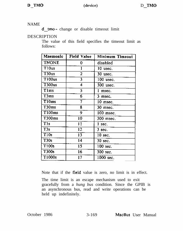
D-TM0 (device) D TM0-
NAMEd_tmo - change or disable timeout limit
DESCRIPTIONThe value of this field specifies the timeout limit asfollows:
Note that if the field value is zero, no limit is in effect.
The time limit is an escape mechanism used to exitgracefully from a hung bus condition. Since the GPIB isan asynchronous bus, read and write operations can beheld up indefinitely.
October 1986 3-169 MacBus User Manual

D-TM0 (device) D-TM0
Timeout values are approximate, though never less thanindicated.
EXAMPLES
1. To change the time limit for device level I/Ooperations involving device tape to approximately 300us:
4 tape d_tma setd
2. To perform I/O operations with no timeout in effect:
0 tape d_tmo setd
MacBus User Manual 3-170 February 1987

GPIB Port and Device Configuration Tables
To inspect or change MacBus GPIB port configuration table, usethe IBCL words getb and setb, respectively. These words have thefollowing syntax:
field-word getbnew field word setb-
( current value on stack )( replace old value with new )
The valid MacBus GPIB port level field words are:
Field Word Field Interpretation
b_uflags contains a set of bits used to track informationpertinent to the MacBus GPIB port. You may setand monitor the value of this field using setb andgetb, just like the other port level configurationwords. The bit definition of the b_uflags fieldis as follows:
Bit # Meaning When Set
01
2
34
5678910
11
Assert EOI with last byte of each writeHold off handshake at the end of eachreadTerminate read when end of stringreceivedAssert EOI with end of string byteUse 8-bit compare on the end of stringbyteTerminate I/O operation on device clearTerminate I/O on address status changereservedreservedGPIB port individual status (IST) bitMacBus will assert remote enable whenit is System ControllerMacBus is System Controller
February 1987 3-171 MacBus User Manual

IBCL o National Instruments
12
1314
Tri-state timing is enabled (fastertransfers)Repeat addressing is disabledAutomatic serial polling is disabled
b_eos end of string fieldb_eot end termination modeb-pad MacBus GPIB port primary addressb-sad MacBus GPIB port secondary addressb_tmo MacBus GPIB port timeout value
All of these fields are very similar to their device counterpartsexcept the primary and secondary addresses. The PAD and SADfields in the device tables specify the address MacBus uses when ittries to communicate with the devices in question. The PAD andSAD fields in the MacBus GPIB port table specify the addressesthat MacBus RESPONDS to as its own addresses.
The MacBus GPIB port configuration table also has a fielddetermining whether or not the board uses DMA for GPIBtransfers. Switching between DMA and program controlled I/O ismore difficult than simply changing a configuration field, so setbdoes not work on this field. The IBCL word bdma achieves thetransition. For example, to use DMA for GPIB transfers, use:
1 bdma
To use programmed I/O for GPIB transfers, use:
0 bdma
Advanced Features
IBCL offers one other powerful GPIB management tool. UsingIBCL, you may install handlers that IBCL will automaticallyexecute when a GPIB interrupt occurs or a device requests service.The words supporting this ability are:
MacBus User Manual 3-172 February 1987

o National Instruments IBCL
onirq ( irq --) When used in the form
irq onirq xxxxx
onirq will request that the IBCL word xxxxxbe executed when the GPIB interrupt irqoccurs. irq is one of the following:
SRQI - service requestDCAS - device clearDTAS - device triggerADSC - address status changeTACS - talker status changeLACS - listener status changeCIC - controller-in-charge status changeREMC - remote/local status changeLOKC - lockout status change
If you use the digit 0 for xxxxx, onirq recognizesthis as a special value and turns OFF handling ofthat interrupt. For instance, to disableautomatic serial polling, use the command string
SRQI onirq 0
This disables automatic serial polling.
onrqs (d m v --) When used in the form:
d m v onrqs xxxxx
onrqs will request that the IBCL word xxxxx becalled when GPIB device d requests service witha status byte (stb) which satisfies the test(m & spr)==v. In order for onrqs to operate, thedefault onirq for SRQ must not be changed.
February 1987 3-173 MacBus User Manual
o National InstrumentsIBCL
Additional GPIB Words
IBCL contains several other words for GPIB management thatwere implemented specifically to ease development of theMegamax C MacBus Support Library. You will probably neverhave cause to use these words, but this section documents themanyway, just in case.
Configuration Control
The following words change a MacBus GPIB port or deviceconfiguration table field and return the old value in the variableibret. Words beginning with b are MacBus GPIB port words andhave the syntax:
new-val bxxxxxx
Words starting with i are device words and have the syntax:
device new val ixxxxx-
Field ChangingWord
bidma
bieosieos
bieotieot
bipadipad
MacBus User Manual
Field Affected
When new_val is zero, MacBus usesprogrammed control I/O for GPIBtransfers; when non-zero, MacBususes DMA
MacBus GPIB port end of string fielddevice end of string field
MacBus GPIB port timeout fielddevice timeout field
MacBus GPIB port primary addressdevice primary address
3-174 February 1987

Q National Instruments IBCL
bisadisad
MacBus GPIB port secondary addressdevice secondary address
GPIB-Macintosh Direct Transfer Words
The MacBus Support Library provides functions which transferGPIB data and commands directly to/from Macintosh memory.These are synchronous functions; however, control doesn’t returnuntil the transfer is 100% complete. In some applications youmight be able to exploit parallel processing if you could continueto run your Macintosh program while MacBus handled the GPIB.Using the following IBCL words, you can construct your ownasynchronous GPIB functions.
bprd ( II --) bprd instructs IBCL to read n bytes fromthe GPIB using brd and then to uploadthe memory to the host by executing ulm.
prd ( d n --) prd instructs IBCL to read n bytes fromGPIB device d using rd and then toupload the memory to the host by executingulm.
bpwt ( n --) bpwt instructs IBCL to obtain n bytes ofdata from the host by executing dlm andthen to write the data to the GPIB using bwrt.
pwt ( d n --) pwt instructs IBCL to obtain n bytes ofdata from the host by executing dlm andthen to write the data to GPIB device d usingwrt.
Data moving between the GPIB and the Macintosh must “stop offin MacBus memory temporarily; the possibility of memoryexhaustion exists. The IBCL word avail? leaves in ibret thenumber of bytes available as a temporary transfer buffer. Youshould never need to use this word; it is built into bprd, prd,
February 1987 3-175 MacBus User Manual

IBCL o National Instruments
bpwt, and pwt.
IBCL Heap Management Words
IBCL provides a sophisticated heap manager to manage memoryresources on MacBus. The heap manager interface is provided bythe following words:
<alloo (n - - s) Allocate an n-byte buffer and return itssegment address.
allot ( n - - ) When used in the form:
n allot buf
allot allocates an n byte buffer and createsan IBCL word buf that will leave the buffer’ssegment address on the stack when executed.
free (s --) Free the buffer starting at segment address s.
The heap manager automatically reclaims free space and mergesadjacent free blocks into larger, single free blocks.
The heap is initialized by the ibcl word init-heap. Once you haveinitialized the heap, you MUST NOT use any segmentmanagement words, nor even create a new IBCL vocabulary. Allsegment management should be part of the application compilationprocess, and the heap should be initialized after the applicationbegins execution. init-heap has no stack arguments.
The skeleton of a sample MacBus session might look like this:
vocabulary application( define application words and data here): final-word init-heap word1 word2 etc... ;final-word( run application)
Note that the application program should not use segment
MacBus User Manual 3-176 February 1987

o National Instruments IBCL
management words as part of its algorithm.
Memory Dumping Words
Memory dumps can aid the program debugging processconsiderably. IBCL provides two dump words, one for nearaddresses and one for segment addresses:
dump (a n --) Dumps n bytes starting at offset ain the default data segment.
ldump (s a n --) Dumps n bytes starting at long address s:a.
February 1987 3-177 MacBus User Manual

a National Instruments Technical Information
SECTION FOUR - TECHNICALINFORMATION
This section provides technical information about MacBus. Thisinformation is provided to allow knowledgeable users to interfacecompatible interface cards to their systems. This section describesthe physical, environmental, and electrical specifications forMacBus as well as a technical description of the major systemcomponents.
PHYSICAL SPECIFICATIONS
MacBus measures 6 inches high, by 11 3/4 inches wide, by 15 l/4inches deep and weighs approximately 15 pounds. The unit canaccommodate up to three optional IBM PC or IBM PC ATcompatible interface cards in addition to the two standard cardswhich come with the unit.
ENVIRONMENTAL SPECIFICATIONS
The GPIB-V50 is designed for use under the followingenvironmental conditions:
Storage Temperature: 0 to 70 degrees COperating Temperature: 10 to 40 degrees CHumidity: 10% to 95% non-condensing
October 1986 4 - l MacBus User Manual

Technical Information D National Instruments
ELECTR.ICAL SPECIFICATIONS
The electrical specifications for the MacBus power supply are asfollows:
Input Voltages: 90V to 130V (115V nominal)or
18OV to 260V (230V nominal)Input Frequency: 47-440 HZInrush Current: 20A maximum peak at cold startFuse on Input Line: 2.5A, 250V+5VDC Current: 13A max *+12VDC Current: 5A max *- 12VDC Current: 1A max *Max Output Wattage: 1oow
* Note: Maximum current cannot be drawn from all outputssimultaneously. At no time should the averagepower (excluding transients) exceed the maximumoutput wattage.
The electrical specifications for the GPIB-V50 and SCSI-PCboards are as follows:
GPIB-V50: +SVDC 1.45A typicalSCSI-PC: +SVDC 380mA typical
MacBus User Manual 4-2 October 1986

0 National Instruments Technical Information
DETAILED DESCR,IPTION
MacBus consists of three basic components: an enclosure, aSCSI-PC interface, and a GPIB-VSO microprocessor card. TheMacBus operating system is contained in ROM on the GPIB-V50card and is called the Interface Bus Interactive Control program(IBCL). IBCL handles all system interaction including SCSI I/Oand all IEEE-488 functions.
Enclosure
The enclosure is an “AT style” box complete with a switchingpower supply, room for up to three disk drives, and amotherboard with connectors for either IBM PC or IBM PC ATstyle cards. The switching power supply supplies +12VDC,-12VDC, and +SVDC to the I/O connectors. Because of thenature of switching power supplies, it is necessary to load theoutputs so that a minimum amount of current will flow from thesupply. The MacBus interface cards, as shipped from the factory,do not draw enough current to properly load down the +5V or+12V supply outputs. For dependable operation these lines havebeen loaded with power resistors which are connected to the insideof the chassis case.
If optional interface cards are added, it is possible that the cardswill load down the power supply outputs so that the powerresistors are no longer needed. If this is the case, remove theresistors from the circuit by disconnecting the connector betweenthe resistors and the supply.
Caution: The power resistors get extremely hot after only a fewminutes of operation. Never touch the resistors after operationand avoid touching the area around where the resistors areconnected.
Use the following guidelines to help you determine when theresistors should be disconnected.
1. If, when adding optional interface cards, the total currentdraw (typical) from all the boards in the system exceeds 6.OA
October 1986 4-3 MacBus User Manual

Technical Information Q National Instruments
on the +5V line, then disconnect the power resistor with thered and black wires.
2. If, when adding optional interface cards, the total currentdraw (typical) from all the boards in the system exceeds 2Aon the +12V line, then disconnect the power resistor with thered and blue wires.
The typical current draw for the GPIB-V50 and SCSI-PC cards isgiven on page 4-2.
Also, remember if you remove a board or boards from yoursystem and the total current draw falls under the thresholds givenabove, then you need to reconnect the resistors.
SCSI-PC Interface
The factory configurations for the SCSI-PC are shown below:
Factory Setting
SCSI-PC I/O Addresses: 330-33F hexSCSI ID: 6Interrupt level: 5DMA channel: 3Terminating Resistors: present
The SCSI-PC I/O address, interrupt level, and DMA channelshould not be changed. If any of these parameters conflict withan optional adapter card, the optional adapter card must bechanged so that the conflict is removed. The SCSI ID and thepresence of the terminating resistors can and should be changedunder certain circumstances. To change the SCSI PCconfiguration, open the unit as described in SECTION TWO,Install Internal Options paragraph, and remove the SCSI-PC card.Figure 4-l shows a parts locator diagram for the SCSI-PC card.Use this figure to locate the SCSI ID switch and the terminatingresistors. Refer to the following paragraphs for descriptions ofthese options.
MacBus User Manual 4-4 October 1986
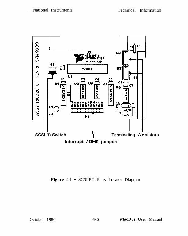
o National Instruments Technical Information
G;
t
ii
C9nw+I31
Pl
IISCSI ID Switch
Cl Od”LD+
UM
Terminating A sistors
Interrupt / DMA jumpers
Figure 4-l - SCSI-PC Parts Locator Diagram
October 1986 4-5 MacBus User Manual

Technical Information D National Instruments
SCSI-PC I/O Addresses
The SCSI-PC interface uses 16 I/O registers from 330 hex to 33Fhex. These I/O registers are hardwired so their locations cannotbe changed. When adding I/O interface adapters, make sure theirI/O addresses do not conflict with those of the SCSI adapter orany other adapter which has been added to the system.
MacBus User Manual 4-6 October 1986

o National Instruments Technical Information
SCSI ID Switch Settings
Each device on the SCSI bus must have its own unique device ID.The Macintosh Plus is set to use SCSI ID 7; the MacBus is shippedfrom the factory with its SCSI ID set to 6. If the MacBus SCSI IDconflicts with another SCSI device, one of the devices SCSI IDSmust be changed to remove the conflict. To change the SCSI IDused by the SCSI-PC, set the switches as shown below for thedesired SCSI ID.
Sl Sl Sl Sl
SCSI ID = 7Do not use.Used by Mac-intosh Plus
Sl
SCSI ID = 6 SCSI ID = 5(Factory Default)
Sl Sl
SCSI ID = 4
I
I, J-11
SCSI ID = 3 SCSI ID = 2 SCSI ID = 1 SCSI ID = 0
Figure 4-2 - SCSI ID Switch Settings
If the SCSI ID is changed from its factory default setting (6), itwill be necessary to run SCSI conf to notify the software of the
-SCSI ID setting change.
February 1987 4-7 MacBus User Manual

Technical Information D National Instruments
DMA Settings
The SCSI-PC interface uses DMA channel 3 for high-speedtransfers between the SCSI bus and GPIB-VSO memory. Optionalinterface boards can use any DMA channel other than channel 3(or 7 since it is connected to channel 3). The jumpers on theSCSI-PC must be jumpered as shown in Figure 4-3 beforerunning any software applications from the Macintosh Plus.
Figure 4-3 - SCSI-PC DMA Channel 3 Setting
MacBus User Manual 4-8 February 1987

o National Instruments Technical Information
Interrupt Settings
The SCSI-PC uses interrupt level 5. Optional interface cards canuse any interrupt level other than level 5. The interrupt jumperon the SCSI-PC must be jumpered as shown in Figure 4-4 beforerunning any software applications from the Macintosh Plus.
Figure 4-4 - SCSI-PC Interrupt Level 5 Setting
Terminating Resistors
The SCSI standard dictates the use of termination resistors on allSCSI signal lines for the first and last device on the SCSI bus. Thefirst and last devices are defined as the two devices which areconnected to only one other SCSI device. If, for example, MacBusand the Macintosh Plus are the only two SCSI devices, then theyboth will use terminating resistors. The SCSI-PC has beendesigned to have the ability of terminating the SCSI lines on thecard. If MacBus is the first or last device on the SCSI bus, makesure that the terminating resistor modules are plugged into theirsockets (U2 and U3 - Figure 4-l). If MacBus is not the first orlast SCSI device, carefully remove these modules and store them ina safe place for future use.
October 1986 4-9 MacBus User Manual

Technical Information o National Instruments
The GPIB-VSO
The system’s RAM is located on the GPIB-VSO card and starts athex 00000 of the 1 Mb address space. The RAM is socketed inthe locations designated Ul through U8 and U16 through U23 onthe GPIB-VSO card.
The RAM subsystem consists of either 16 65,536x1 or 16262,144x1 dynamic RAM modules for a total address space ofeither 128K or 512K, respectively. If the GPIB-VSO card issocketed with 128K bytes of RAM, you can increase your RAMspace by changing the RAM modules; however, the followingprecautions should be made:
l The RAM modules, as well as other system components, can bedamaged by improper handling techniques. Make sure you usea grounded wrist strap and work on a grounded work areawhen changing the RAM modules.
. Memory chips should be change only with the same orcompatible type of RAM modules with a maximum access timeof 120 nanoseconds.
l All 16 RAM locations must be socketed with the same type ofRAM modules - either 64Kxl or 256Kxl.
There are no user contigurable jumpers or switches on the GPIB-V50 card. The system dynamically determines the amount ofRAM on power-up and all other available options are configurablein software through IBCL function calls.
Although the GPIB-VSO was designed to allow interfacing to IBMPC and IBM PC AT compatible interfaces, there are a few notabledifferences between the signals supported on the GPIB-VSO I/Oconnector and those provided on an IBM PC AT. Thesedifferences are listed below:
l LA17 through LA23 are not supported on the GPIB-VSO
l CLK is an 8 MHz signal
. OWS is not supported on the GPIB-VSO
MacBus User Manual 4-10 October 1986

o National Instruments Technical Information
. DRQO and -DACKO are connected to the on-board GPIBcircuitry but can be disconnected in software if they areneeded by another board
l 16-bit bus operations to 8-bit devices are not supported on theGPIB-V50
. The seven IBM PC AT DMA channels are mapped into thefour GPIB-V50 channels as shown below (DMA Channel 0 isthe highest priority). The DMA acknowledge signals aremapped accordingly.
DMA 62-pin 36-pin Transfer TypeChannel Connector Connector Supported
0 not bussed DRQO(D09) 8-bit1 DRQl DRQS(D11) 8- o r 1 6 - b i t
(programmable)2 DRQ2 DRQ6(D13) 8- o r 1 6 - b i t
(programmable)3 DRQ3 DRQ7(D15) used by the
SCSI-PC card
Notice that even though the I/O bus provides seven separatechannels for DMA, only a maximum of four can be used at atime (including the DMA channel used for GPIB operation).
. The 11 IBM PC AT interrupt levels are mapped into the sixavailable V50 interrupt levels as shown below (V50 interruptlevel 2 has the highest priority).
October 1986 4-11 MacBus User Manual
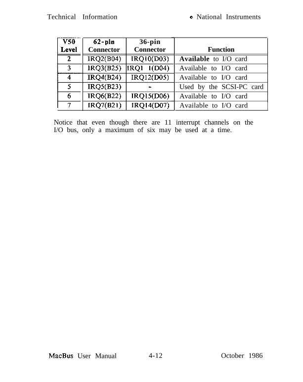
Technical Information Q National Instruments
v50cLevel2
62-pin 36-pinConnector ConnectorIRQ2(B04) IRQlO(D03)IRQ3(B25) IRQl l(D04)IRQ4(B24) IRQl2(D05)IRQ5(B23) -IRQ6(B22) IRQ15(D06)IRQ7(B21) IRQ14(D07)
FunctionAvailable to I/O cardAvailable to I/O cardAvailable to I/O cardUsed by the SCSI-PC cardAvailable to I/O cardAvailable to I/O card
Notice that even though there are 11 interrupt channels on theI/O bus, only a maximum of six may be used at a time.
MacBus User Manual 4-12 October 1986

B National Instruments Diagnostics & Troubleshooting
SECTION FIVE - DIAGNOSTICS &TFtOUBLESHOOTING
This section is designed to help you determine the cause of anyproblem you may be having with your MacBus setup. A checklistis provided to help you troubleshoot your system. If for somereason you cannot solve the problem with the procedures outlinedbelow, call National Instruments for further instructions.
WHERE TO BEGIN
The following checklist should be read and followed before youtry more involved troubleshooting procedures:
Is the AC power cord attached properly and plugged into anoutlet of the correct voltage (the voltage is noted on the labelto the right of the fan outlet)?
Is the power switch to MacBus and all other SCSI devices inthe ON position?
Is the SCSI cable attached and seated correctly on MacBus, theMacintosh Plus, and any optional SCSI devices?
Do all SCSI devices have their own unique SCSI ID?
Did you power all SCSI devices on well in advance (10 seconds)of powering on your Macintosh Plus?
Did you make sure any optional plug in cards are compatiblewith MacBus and have their own unique address space,interrupt lines, and DMA channels?
If the above checklist has been read and followed and you are stillexperiencing a problem, it will be necessary to narrow theproblem down to a specific type. The problems most likely tooccur are problems caused by incorrect programming techniquesor optional system components such as plug-in cards or SCSIdevices. By following the procedures below you should be able todetermine the cause of the problem and correct it yourself.
October 1986 5- l MacBus User Manual

Diagnostics & Troubleshooting o National Instruments
CHECK ELECTRICAL CONNECTIONS
1.
2.
3.
4.
5.
Turn the system unit switch to the OFF position.
Unplug the system unit’s power cord from the wall outlet.
Check the wall outlet by plugging in a working lamp.
Disconnect and reconnect each cable on MacBus, includingthe power cord, to ensure proper electrical connection.
Plug the MacBus power cord back into the wall outlet andturn the system unit switch to the ON position. Listen for thesound of the fan in the unit. If the fan does not operatewhen the unit is powered on, the MacBus fuse may beblown. The fuse may be replaced by opening the unit andremoving the cover of the power supply. Remove power toMacBus before opening the unit as dangerous voltages arepresent inside the power supply unit. Replace only with thesame type and rating of fuse.
ISOLATE THE SYSTEM
If the system was configured to have other SCSI devices or plug-in cards, there is a chance that these options could be causing aproblem because 1) they themselves are not working properly, 2)they are not compatible with the MacBus system interface, or 3)the devices are set up improperly or have conflicting interfaceparameters. In any event, you will be able to determine if thesedevices are causing your problem by removing them from yoursystem as described below.
1. Turn the power switch of the Macintosh Plus, MacBus, andall SCSI peripherals to OFF.
2. Remove all external SCSI peripherals by disconnecting theircables from the SCSI daisy chain.
3. Remove all plug-in cards, except the GPIB-V50 card and theSCSI-PC card, from the MacBus backplane.
MacBus User Manual 5-2 October 1986

o National Instruments Diagnostics & Troubleshooting
4. Make sure the SCSI card is set to the factory default settings.These settings are given on page 4-4. Also, make sure theSCSI terminating resistors are installed in the SCSI-PC board.
5. Connect the SCSI cable to the Macintosh Plus and to MacBus.
RUN DIAGNOSTIC SOFTWARE
The diagnostic software sends a command to MacBus which tells itto return the results from the power-on self-test. The resultsfrom the test will be posted on the Macintosh Plus screen to aidyou in determining the problem. If MacBus is unable to send anyinformation back to the Macintosh Plus, the diagnostic softwarewill post a SCSI bus error.
1. Check all electrical connections then power up MacBus. Wait10 seconds and then power on your Macintosh Plus.
2. Insert the distribution disk, which came with your MacBus,in the Macintosh Plus disk drive and double click on theIBDIAG icon when it appears. This will start the on-boarddiagnostic routines on MacBus.
3. The results from the diagnostics are displayed on theMacintosh screen. The following is a list of possible errormessages.
Error Code Description
0 No errors1 ROM checksum failure2 CPU internal register failure3 CPU on-board peripheral failure4 RAM failure5 GPIB failure
t 6 SCSI bus error
October 1986 5-3 MacBus User Manual

Diagnostics & Troubleshooting Q National Instruments
4. If the diagnostics pass, then one or more of the options youwere using in your system may be causing MacBus tomalfunction. Try reinstalling the options one-by-one untilyou determine which option is causing the system tomalfunction. If the diagnostics fail then there is a possibilitythat MacBus is not functioning properly. Check that theboards are plugged in correctly and that all electricalconnections are made. If the diagnostics still do not pass,call National Instruments to get a Return MaterialAuthorization (RMA) number before returning the productfor service.
MacBus User Manual 5-4 October 1986

APPENDIX A - MULTILINE lTWERJ?ACEMESSAGES
Multiline interface messages are sent and received with ATNTRUE.
October 1986 A - l MacBus User Manual

Hex Ott Dee ASCII Msg
00 000 NUL01 001 SOH GTL02 002 STX03 003 ETX04 004 EOT SDC05 005 ENQ SDC06 006 ACK07 007 BEL
Hex Ott Dee ASCII Msg
20 040 3221 041 3322 042 3423 043 3524 044 3625 045 3726 046 3827 047 39
SP!I,
:%&,
MLAOMLAlMLA2MLA3MLA4MLA5MLA6MLA7
08 008 8 BS GET 28 050 4009 009 9 HT TCT 29 051 41OA 012 10 LF 2A 052 42OB 013 11 VT 2B 053 43o c 014 12 FF 2c 054 44OD 015 13 CR 2D 055 45OE 016 14 s o 2E 056 46OF 017 15 SI 2F 057 47 i
MLA8MLA9MLAlOMLAllMLA12MLA13MLA14MLAl5
10 020 16 DLE 30 060 48 0 MLA1611 021 17 DC1 LLO 31 061 49 1 MLA1712 022 18 DC2 32 062 50 2 MLA1813 023 19 DC3 33 063 51 3 MLA1914 024 20 DC4 DCL 34 064 52 4 MLA2015 025 21 NAK PPU 35 065 53 5 MLA2116 026 22 SYN 36 066 54 6 MLA2217 027 23 ETB 37 067 55 7 MLA23
18 030 24 CAN SPE 38 070 5619 031 25 E M S P D 39 071 571A 032 26 SUB 3A 072 581B 033 27 ESC 3B 073 591c 034 28 FS 3c 074 601D 035 29 GS 3D 075 611E 036 30 RS 3E 076 621F 037 31 u s 3F 077 63
89
MLA24MLA25MLA26MLA27MLA28MLA29MLA30UNL
Multiline Interface Messages 0 National Instruments
MacBus User Manual A-2 October 1986

National Instruments 0 Multiline Interface Messages
Hex Ott Dee ASCII Msg H e x Ott Dee A S C I I Msg
40 100 64 @ MTAO 60 140 96 ‘ MSAO,PPE41 101 65 A MTA 1 61 141 97 MSA 1 ,PPE42 102 66 B MTA2 62 142 98 : MSA2,PPE43 103 67 C MTA3 63 143 99 MSA3,PPE44 104 68 D MTA4 64 144 100 “d MSA4,PPE45 105 69 E MTA5 65 145 101 e MSA5,PPE46 106 70 F MTA6 66 146 102 f MSA6,PPE47 107 71 G MTA7 67 147 103 g MSA7,PPE
48 110 72 H MTA8 68 150 104 h MSA8,PPE49 111 73 I MTA9 69 151 105 i MSA9,PPE4A 112 74 J MTAIO 6A 152 106 j MSAlO,PPE4B 113 75 K MTAll 6B 153 107 k MSAl 1 ,PPE4c 114 76 L MTA12 6C 154 108 1 MSAl2,PPE4D 115 77 M MTA13 6D 155 109 m MSAl3,PPE4E 116 78 N MTA14 6E 156 110 n MSAl4,PPE4F 117 79 0 MTA15 6F 157 111 0 MSAl5,PPE
50 120 8051 121 8152 122 8253 123 8354 124 8455 125 8556 126 8657 127 87
isTUVW
MTA16 70 160 112 p MSA 16,PPDMTA17 71 161 113 q MSAl7,PPDMTA18 72 162 114 r MSAl8,PPDMTA19 73 163 115 s MSAl9,PPDMTA20 74 164 116 t MSA20,PPDMTA2 1 75 165 117 u MSA2 1 ,PPDMTA22 76 166 118 v MSA22,PPDMTA23 77 167 119 w MSA23,PPD
58 130 8859 131 895A 132 905B 133 915c 134 925D 135 935E 136 945F 137 95
XY
r”\1h
-
MTA24 78 170 120 x MSA24,PPDMTA25 79 171 121 y MSA25,PPDMTA26 7A 172 122 2 MSA26,PPDMTA27 7B 173 123 ( MSA27,PPDMTA28 7 c 174 124 1 MSA28,PPDMTA29 7D 175 125 > MSA29,PPDMTA30 7E 176 126 - MSA30,PPDUNT 7F 177 127 DEL
October 1986 A-3 MacBus User Manual

APPENDIX B - THE GPIB
The IEEE-488, also known as the General Purpose Interface Busor GPIB, is a high speed parallel bus structure originally designedby Hewlett-Packard. It is generally used to connect and controlprogrammable instruments, but has gained popularity in otherapplications, such as intercomputer communication and peripheralcontrol.
TYF’ES OF MESSAGES
The GPIB carries device-dependent messages and interfacemessages.
. Device-dependent messages, often called data or datamessages, contain device-specific information such asprogramming instructions, measurement results, machinestatus, and data files.
l Interface messages manage the bus itself. They are usuallycalled commands or command messages. Interface messagesperform such functions as initializing the bus, addressing andunaddressing devices, and setting device modes for remote orlocal programming.
The term command as used here should not be confused withsome device instructions which can also be called commands.Such device-specific instructions are actually data messages.
TALKERS, LISTENERS, AND CONTROLLERS
A Talker sends data messages to one or more Listeners. TheController manages the flow of information on the GPIB bysending commands to all devices.
Devices can be Listeners, Talkers, and/or Controllers. A digitalvoltmeter, for example, is a Talker and may be a Listener as well.
October 1986 B-l MacBus User Manual

The GPIB Q National Instruments
The GPIB is a bus like an ordinary computer bus except that thecomputer has its circuit cards interconnected via a backplane buswhereas the GPIB has standalone devices interconnected via acable bus.
The role of the GPIB Controller can also be compared to the roleof the computer’s CPU, but a better analogy is to the switchingcenter of a city telephone system.
The switching center (Controller) monitors the communicationsnetwork (GPIB). When the center (Controller) notices that a party(device) wants to make a call (send a data message), it connectsthe caller (Talker) to the receiver (Listener).
The Controller usually addresses a Talker and a Listener beforethe Talker can send its message to the Listener. After the messageis transmitted, the Controller usually unaddresses both devices.
Some bus configurations do not require a Controller. For example,one device may always be a Talker (called a Talk-only device) andthere may be one or more Listen-only devices.
A Controller is necessary when the active or addressed Talker orListener must be changed. The Controller function is usuallyhandled by a computer.
The MacBus system permits your Macintosh Plus to play all threeroles.
l Controller - to manage the GPIB
. Talker - to send data
. Listener - to receive data
THE CIC AND SYSTEM CONTROLLER
Although there can be multiple Controllers on the GPIB, only oneController at a time is active or Controller-In-Charge (CIC).Active control can be passed from the current CIC to an idleController. Only one device on the bus, the System Controller,can make itself the CIC. MacBus is usually the System Controller.
MacBus User Manual B-2 October 1986

National Instruments 8 The GPIB
GPIB SIGNALS AND LINES
The interface system consists of 16 signal lines and 8 groundreturn or shield drain lines.
The 16 signal lines are divided into the following three groups.
l 8 data lines
. 3 handshake lines
. 5 interface management lines
Data Lines
The eight data lines, DIOl through D108, carry both data andcommand messages. All commands and most data use the 7-bitASCII or IS0 code set, in which case the 8th bit, D108, is unusedor used for parity.
Handshake Lines
Three lines asynchronously control the transfer of message bytesamong devices. The process is called a three-wire interlockedhandshake and it guarantees that message bytes on the data linesare sent and received without transmission error.
NRFD (not ready for data)
NRFD indicates when a device is ready or not ready to receive amessage byte. The line is driven by all devices when receivingcommands and by Listeners when receiving data messages.
NDAC (not data accepted)
NDAC indicates when a device has or has not accepted a messagebyte. The line is driven by all devices when receiving commandsand by Listeners when receiving data messages.
DAV (data valid)
October 1986 B-3 MacBus User Manual

The GPIB 8 National Instruments
DAV tells when the signals on the data lines are stable (valid) andcan be accepted safely by devices. The Controller drives DAVwhen sending commands and the Talker drives it when sendingdata messages.
Interface Management Lines
Five lines are used to manage the flow of information across theinterface.
ATN (attention)
The Controller drives ATN true when it uses the data lines tosend commands and false when it allows a Talker to send datamessages.
IFC (interface clear)
The System Controller drives the IFC line to initialize the bus andbecome CIC.
REN (remote enable)
The System Controller drives the REN line, which is used to placedevices in remote or local program mode.
SRQ (service request)
Any device can drive the SRQ line to asynchronously requestservice from the Controller with the SRQ line.
EOI (end or identify)
The EOI line has two purposes. The Talker uses it to mark theend of a message string. The Controller uses it to tell devices toidentify their response in a parallel poll.
MacBus User Manual B-4 October 1986

National Instruments 0 The GPIB
PHYSICAL AND ELECTRKXL CHARACTERISTICS
Devices are usually connected with a cable assembly consisting ofa shielded 24 conductor cable with both a plug and receptacleconnector at each end. This design allows devices to be linked ineither a linear or a star configuration, or a combination of thetwo. See Figures B-l, B-2, and B-3.
The standard connector is the Amphenol or Cinch Series 57MICRORIBBON or AMP CHAMP type. An adapter cable usingnon-standard cable and/or connector is used for specialinterconnect applications.
The GPIB uses negative logic with standard TTL logic level.When DAV is true, for example, it is a TTL low level ( 5 O.SV),and when DAV is false, it is a TTL high level ( 2 2.OV).
October 1986 B-5 MacBus User Manual

The GPIB 0 National Instruments
DIOS
E%:DI08RENGND [TW PAIR WPAVIGND [TW PAIR W/NRFDlGND [TW PAIR W/NDAClGND [TW PAIR W/IFClGND [TW PAIR W/SRQIGND yrW PAIR W/ATNlSIGNAL GROUND
Figure B-l - GPIB Connector and the Signal Assignment
MacBus User Manual B-6 October 1986

National Instruments ~3 The GPIB
October 1986
Figure B-2 - Linear Configuration
B-7 MacBus User Manual

The GPIB 0 National Instruments
I Device A I Device DI
Figure B-3 - Star Configuration
MacBus User Manual B-8 October 1986

National Instruments 0 The GPIB
CONFIGURATION REQUIR.EMENTS
To achieve the high data transfer rate that the GPIB was designedfor, the physical distance between devices and the number ofdevices on the bus are limited.
The following restrictions are typical.
. A maximum separation of four meters between any twodevices and an average separation of two meters over theentire bus.
. A maximum total cable length of 20 meters.
. No more than 15 devices connected to each bus, with at leasttwo-thirds powered on.
Bus extenders are available from National Instruments and othermanufacturers for use when these limits must be exceeded.
RELATED DOCUMENTS
For more information on topics covered in this section consult thefollowing related documents.
. IEEE Std. 488-1978, “IEEE Standard Digital Interface forProgrammable Instrumentation.”
l MacBus Technical Reference Manual.
October 1986 B-9 MacBus User Manual

APPENDIX C - IBCL COMMAND SUMMARY
key: n 16 bit integerU 16 bit unsigned integeri 16 bit signed integer
d 32 bit integerdu 32 bit unsigned integerdi 32 bit signed integer
S 16 bit segment paragraph number
#C
xxx
iC
Note:
word____
!
! %
! e
!l
#
#>
#S
a 16 bit ds relative addresse 16 bit es relative addressuv 16 bit ds relative addresssd 16 bit ds relative addressfcb 16 bit ds relative address
of user variableof segment descriptorof file control block
16 bit character countuse only lower byte of 16 bit number
a name to be entered into or found in a vocabulary,or a filename
imnediate, executes from compile modeuse this word only while compiling
the right.
description___________
top of stack is to
stack_____
before - after
n a -U C - u+lne-
nsa-dul - du2
du - a c
du - 0 0
store word n at ds:astore byte c at cs:u and return u+lstore word n at es:estore word n at s:aextract next digit of dul and send to output
stringend pictured numeric conversion, return
address and count for typeextract remaining digits from du and send to
February 1987 C - l MacBus User Manual

IBCL Command Summary @ National Instruments
S!
Svar-far xxx sd n -
al a2 -S! 1
gxchg
sl al s2 a2 -
al a2 -
S=
%>
sl al s2 a2 - fS+
’ xxx
al a2 - padS+t
- a
sl al s2 a2 - pad
ic
Sconstant xxx string”Semi t n c-Sfind a0 sl al a2 - sl a3 fSline
StYpe a -Svariable x x x n -
output stringcopy string from al to a2copy string from sl:al to s2:a2
allot n byte string variable in segment sd
compare stringsconcatenate stringsconcatenate strings
exchange string at sl:al with s2:a2
initialize string constantwrite block of length n of c
terminate machine code byte list
find string a0 in sl:al...sl:a2read line from keyboard to padblock write of (S) string at a
return parameter field address of next word,
allot n byte string variable
error if not found
The following are user variables which contain the code fieldaddress currently assigned to the word left after dropping theleading tick.
‘ - f ind‘word*abort‘interpretII
Icr
‘expect
-- s 0 n
( cotnsent) -* il i2 - i3*/ il i2 i3 - i4
*/mod il i2 i3 - i4 i5+ nl n2 - 173+! n a -+- il i2 - i3+>r n -+buf al - a2 f
+code xxx+is name n l n 2 -+1oop i -
MacBus User Manual
‘vocabulary
‘nunber
take text from the input stream up to theclosing II and place n bytes at segment s,offset 0
coranent, ignore characters until )signed product of il and i2signed 32 bit product of il and i2 divided
by i3 8 rounded toward 0l i k e */ i4=remainder i5=quotientsigned or unsigned sum of nl & n2add n onto word value at ds:areturn il, negated if i2 is negativeadd n to top number on return stackreturn address of next disk buffer f is false
if a2 is prev buffername entry for overlaid codestore nl at pfa+2+(2*n2)do loop terminator using signed index with
step i
c - 2 February 1987

National Instruments 0 IBCL Command Summary
,, words
n -n -
append n to definition lists allot 2 bytesappend n to current vocabulary allot 2 bytes
nl n2 - n3-1 _ _ 1-2 _ _ 2-find xxx - pfa lb t
- f
-text al u a2 - f
- t ra i l ing a #l - a #2
i - type signed integer i with one trailing
. ” msg” ic
.codel xxx
.head*index s# -.line l# s# -.memory
nl minus n2 signed or unsignedconstantconstantreturn pfa, length byte and true if next
word in input stream is found, otherwisereturn false
compare strings at al & a2 over length u,return false if equal
reduce character count to omit trailingblanks
blank using basetype following message until @Idunp machine code for word xxxdunp code for word currently being definedtype s# and line 0 of screen s#type line l# of screen s#display segment names and ranges
. r
.S
.seg
.Sl
.sr
.ss
. word
i u - type i right aligned in a field of ucharacters
stack - stack list data stack in ascending or descendingorder
sd - prevsd type name and range of segment sd then linkto previous segment
set .ss to f for ascending orderset .ss to t for descending order
- f constant, data stack list ordercfa - type word with this cfa
from context vocabulary
/ il i2 - i3 quotient of il divided by i2 rounded towardzero
/loop u - ic do loop terminator using unsigned index andstep u
/mod
0O!O!eOXo=o>
il i2 - i3 i4 il/i2 remainder=i3 quotient=i4
- 0 constanta - store 0 at word address ds:ae - store 0 at word address es:ei - f true if i negativen - f true if n is 0i - f true if i greater than 0
February 1987 c - 3 MacBus User Manual

IBCL Command Summary 0 National Instruments
Obranch f .
Oc!e1I+I+!l-I - !
e -- 1
n - n+la -n - n-la -
2 - 22* i - i*22+ n - n+22+! a -2- n - n-22-! a -2/ i - i / 23 - 34 - 44+ n - n+46+ n - n+6
;;’ xxx
;case; code
<C#<+ 1 oop>
il i2 - fdu - du
i - C
icic
icic
<-find> xxx - pfa lb t- f
<-findw> xxx - lpa lb t- f
<.I’> C
</ 1 oop> u - C
<; code> C
<abort% C
<abort><cmove 1 sl a s2 e # -
anove> a e# -
MacBus User Manual
run time procedure interpreter branches ifflag false
store 0 at byte address es:econstantincrement top word on stackincrement nunber at word addr ds:adecrement top word on stackdecrement number at word addr ds:a
constantmultiply top word on stack by twoadd two to top word on stackincrement number at word address ds:a twicesubtract two form top word on stackdecrement nunbet- at word address ds:a twicedivide by two, round towards zeroconstantconstantadd four to top word on stackadd six to top word on stackbegin high-level colon definitionend colon definitioncreate new defining word which will use
word xxx for execution time routineterminate case: vector tablecreate new defining word which will use
address of following code for executiontime routine
true if il is less than i2initialize pictured nuseric outputrun time procedure for +loopfind pfa and length byte of next word,
return false if not foundas above, but return es relative list
pointer address, leave vocabularysegment pointer in es
type following inline textrun time procedure for /loopreplace code field of most recently defined
word with address of following machine code
run time procedure for abort”clear data 8 return stacks, quitcopy # bytes from block at sl:a to block at
s2:b, beginning with highest addresscopy # bytes from block at ds:a to block at
c - 4 February 1987
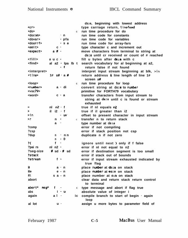
National Instruments 0 IBCL Command Summary
<cr><do><docon><dovar><doarrf><emit><expect>
< f i l l ><find>
C
- n- pfa- sa
c -a#-
auc-al a2 - lpa lb t
- f‘<interpret><line> 1# s# - a #
<loop><number><voc79><word>
a - di
c - a
=>>in>r
?comp?csp?dup
?(?pai rs?seg-size?stack?stream
nl n2 - fil i2 - f
- uvn -a -
n - n nn - 0f -
nl n2 -# sd - # sd
f -
a a - n@e e - n31 s a - nabort
abort” msg” f -abs i - uagain a l -
al lot u -
C
C
C
ic
ds:e, beginning with lowest addresstype carriage return, linefeedrun time procedure for dorun time code for constantsrun time code for variablesrun time code for array-farstype character c and increment outmove characters from terminal to string at
ds:a until cr received or count of # reachedfill u bytes after ds:a with csearch vocabulary for al beginning at a2,
return false if not foundinterpret input stream beginning at blk, >inreturn address & line length of line 1#
screen s#run time procedure for loopconvert string at ds:a to nunberprimitive for FORTH79 vocabularytransfer characters from input stream to
string at ds:a until c is found or streamexhausted
true if nl equals n2true if il greater than i2offset to present character in input streamtransfer n to return stacktype number at ds:aerror if not compilingerror if stack position not cspduplicate n if not zero
ignore until next ) only if f falseerror if nl not equal to n2error if destination segment is too smallerror if stack out of boundserror if input stream exhausted indicated by
true flagplace mmber at ds:a on stackplace nusber at es:e on stackplace number at s:a on stackclear data and return stack return control
to terminaltype message and abort if flag trueabsolute value of integer icompile branch to start of begin - again
loopassign u more bytes to parameter field of
February 1987 C-5 MacBus User Manual
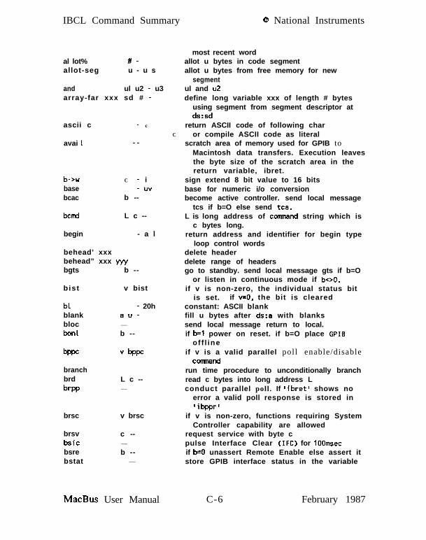
IBCL Command Summary 0 National Instruments
al lot% #-allot-seg u - u s
and ul u2 - u3array-far xxx sd # -
ascii c
avai 1
- c
C__
b->wbasebcac
C - i- uv
b --
bcmd L c --
begin - a l
behead’ xxxbehead” xxx yyybgts b --
b ist v bist
blblankblocbon1
- 20hau-__
b --
Vbppc
branchbrd
brpp
L c --__
brsc v brsc
brsvbsicbsrebstat
c --__
b --__
MacBus User Manual
most recent wordallot u bytes in code segmentallot u bytes from free memory for new
segmentul and u2define long variable xxx of length # bytes
using segment from segment descriptor atds:sd
return ASCII code of following charor compile ASCII code as literal
scratch area of memory used for GPIB toMacintosh data transfers. Execution leavesthe byte size of the scratch area in thereturn variable, ibret.
sign extend 8 bit value to 16 bitsbase for numeric i/o conversionbecome active controller. send local message
tcs if b=O else send tea.L is long address of consand string which is
c bytes long.return address and identifier for begin type
loop control wordsdelete headerdelete range of headersgo to standby. send local message gts if b=O
or listen in continuous mode if boo.if v is non-zero, the individual status bit
is set. if v=O, the bit is clearedconstant: ASCII blankfill u bytes after ds:a with blankssend local message return to local.if b=l power on reset. if b=O place GPIB
of f l ineif v is a valid parallel poll enable/disable
COllllMnd
run time procedure to unconditionally branchread c bytes into long address Lconduct parallel poll. If ‘ibret’ shows no
error a valid poll response is stored in‘ibpprl
if v is non-zero, functions requiring SystemController capability are allowed
request service with byte cpulse Interface Clear (IFC) for IOOmsecif b=O unassert Remote Enable else assert itstore GPIB interface status in the variable
C-6 February 1987
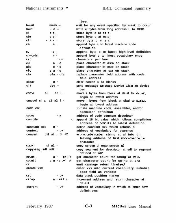
National Instruments 0 IBCL Command Summary
bwait mask --bwrt L c --c! ca-c!e ce-c! 1 csa-c% c -
c,c, wordsC/l
C@
cgeC@l
cfa
c -c -
- lJv
a - ce - c
s a - cpfa - cfa
clearc l r
u -dev --
move al a2 i -
cmovel sl al s2 a2 i -
code xxx
codescompile
- aC
constant xxx n -context - uvconvert di l a l - di a2
copy ul u2 -copy-seg sdl sd2 -
count a - a+1 #count 1 s u - s u+l #crcreate xxx
cspcstep
- uva - a+1 c
current - uv
ibretwait for any event specified by mask to occurwrite c bytes from long address L to GPIBstore byte c at ds:astore byte c at es:estore byte c at s:aappend byte c to latest machine code
definitionappend byte c to latest high-level definitionappend byte c to latest vocabulary entrycharacters per lineplace character at ds:a on stackplace character at es:e on stackplace character at s:a on stackreplace parameter field address with code
field addressclear screen u to blankssend message Selected Device Clear to device
devmove i bytes from block at ds:al to ds:a2,
begin at lowest addressmove i bytes from block at sl:al to s2:a2,
begin at lowest addressinitiate machine code, assembler, and/or
optimizer definitionaddress of code segment descriptorappend 16 bit value which follows compilation
address of conpile to latest definitiondefine constant xxx which returns naddress of vocabulary for searchesaccunulate number string at al into di,
leaving address of first nonconvertablecharacter
copy screen ul onto screen u2copy segment for descriptor at sdl to segment
defined at sd2get character count for string at ds:aget character count for string at s:uemit carriage return linefeedenter xxx into current vocabulary initialize
code field as variabledata stack position markerincrement address and return character at
ds:a+laddress of vocabulary in which to enter new
definitions
February 1987 MacBus User Manual

IBCL Command Summary 0 National Instruments
d!d! 1d+d+-d-d.
d.rdO=d<d=d>dBdB1d_eosd_eo t
dpadd-sadd_tmo
d a -dsa-
dl d2 - ~43d i l i - di2
dl d2 - d3di -
di u-d - f
dil di2 - fdl d2 - f
dil di2 - fa - d
s a - dn -- dn/a
n -- dn -- dn -- ddi - du
dconstant x x x d -ddrop d -ddup d -d ddecimaldefinitions -depth - udigi t c n - u t
fd l i tera l d- icCilMX dil di2 - d i3&sin dil di2 - d i3dnegate di - -dido il i2 - C
does> ic
dover
dpdpl
dl d2 - dl d2 dl- n- a
dropdrop- seg
n -sd - sd
store double word d at address ds:astore double word d at address s:asun double nunbers dl and d2return dil, negated if i was negativesubtract double number dl from d2type double integer di according to base with
one trailing blanktype di right aligned in field of u characterstrue if double word d is zerotrue if dil less than di2true if dl equals d2true if dil greater than di2return double nudoer at ds:areturn double nurber at s:aarg for ‘get’. End of String character.a field in the device configuration table.
if non-zero, the END message is sentautomatically with the last byte of eachwrite operation. if the value is zero,END is not sent
erg for ‘get’. primary GPIB address.erg for ‘get’. secondary GPIB address.erg for ‘get’. time limit.absolute value of double integer didefine double constant xxx which will return ddrop top two words from stackduplicate double numberset base to decimalchange current vocabulary to contextreturn count of words on data stackreturn binary digit corresponding to ASCII
c using base n or false flag if invalidcompile double nunber d on stack as a literalkeep larger of two double numberskeep smaller of two double nunberstwo’s complement of double nunberbegin do loop with index limit ii index
starting at i2define run time action of defining word
(high-level)copy second double nunber on stackshort for dpl @user variable, number of digits after decimal
for last nusberdrop top number from stackextract segment from chain, enlarging one
MacBus User Manual C-8 February 1987
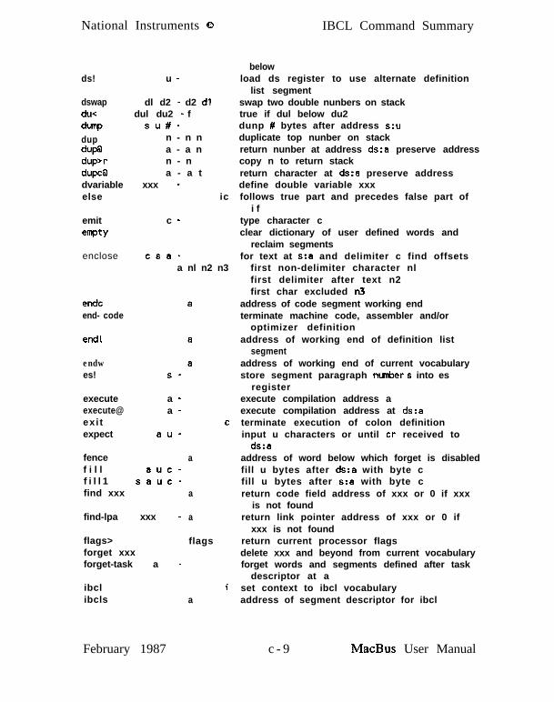
National Instruments 0 IBCL Command Summary
ds! u -
dswap dl d2 - d2 dldu< dul du2 - f
dunp su#-
dup n - n n
dup@ a - a ndup>r n - ndupcg a - a tdvariable xxx -else ic
emit
emptyc -
enclose csa-a nl n2 n3
endcend- code
end1
endwes! s -
execute a -execute@ a -exi texpect au-
fencef i l l auc-f i l l 1 sauc-find xxx
find-lpa xxx -
flags>forget xxxforget-task a -
ibclibcls
February 1987
a
a
a
flags
a
belowload ds register to use alternate definition
list segmentswap two double nunbers on stacktrue if dul below du2dunp # bytes after address s:uduplicate top nunber on stackreturn nunber at address ds:a preserve addresscopy n to return stackreturn character at ds:a preserve addressdefine double variable xxxfollows true part and precedes false part of
i ftype character cclear dictionary of user defined words and
reclaim segmentsfor text at s:a and delimiter c find offsets
first non-delimiter character nlfirst delimiter after text n2first char excluded n3
address of code segment working endterminate machine code, assembler and/or
optimizer definitionaddress of working end of definition list
segmentaddress of working end of current vocabularystore segment paragraph tnnnber s into es
registerexecute compilation address aexecute compilation address at ds:aterminate execution of colon definitioninput u characters or until cr received to
ds:aaddress of word below which forget is disabledfill u bytes after ds:a with byte cfill u bytes after s:a with byte creturn code field address of xxx or 0 if xxx
is not foundreturn link pointer address of xxx or 0 if
xxx is not foundreturn current processor flagsdelete xxx and beyond from current vocabularyforget words and segments defined after task
descriptor at aset context to ibcl vocabularyaddress of segment descriptor for ibcl
c - 9 MacBus User Manual

IBCL Command Summary @ National Instruments
herehere-chere-whexhld
holdhop.ii’
i !i ! ei!li+!i+!ei+! 1igigeiglic!ic!eic! 1ic@i cgeicglid!id!eid! 1id@id@eid@1i f
- a- a- a
- uv
c -pfa -
- n- n
nau-neu-
nsau-nau-neu-
nsau-a u - ne u - n
s a u - ncau-ceu-
cseu-a u -eu-
sau-dau-deu-
dsau-a u - de u - d
s a u - df -
C
C
ic
inzaediateins - padin# - dintcallf a b c d #i - a’ t
finterpret
is name n - i
j - n C
label-far xxx sa-
MacBus User Manual
vocabulary segmentworking end of definition listsworking end of code segmentworking end of current vocabularyset base to hexadecimaladdress of latest character of text for numeric
outputinsert c in pictured nuneric stringmacro, execute high-level wordreturn loop indexreturn loop index buried one deep
store word n at ds:a+ustore word n at es:e+ustore word n at s:a+uadd word n to word at ds:a+uadd word n to word at es:e+uadd word n to word at s:a+uplace word at ds:a+u on stackplace word at es:e+u on stackplace word at s:a+u on stackstore char c at ds:a+ustore char c at es:e+ustore char c at s:a+uplace char at ds:a+u on stackplace char at es:e+u on stackplace char at s:a+u on stackstore dword d at ds:a+ustore dword d at es:e+ustore dword d at s:a+uplace dword at ds:a+u on stackplace dword at es:e+u on stackplace dword at s:a+u on stackif flag true, execute following words until
else or thenmake last word defined imnediateprompted string inputprompted double nusber inputlike intcall, for interrupts that indicate
success by setting carry flag to zerointerpret input stream at offset Sin
characters into blkset parameter field to nreturn index of next to innermost
do loopdefine label xxx to return
c - 1 0 February 1987

National Instruments @ IBCL Command Summary
last-seg - a
latest - e
leave
l imitl is ts
- a- a
l i t - nl i t e r a l n -110 dev - -load n -lot dev - -locate-word cfa - lpa t
f1 oop
lpa al - a2
m* il i2 - di
m*/ dil il i2 - di2 triple precision product of dil & il divided by
m+ d l n - d 2m/ di nl - n2 n3
m/mod dul ul - u2 du2make-list xxx #matchmax il i2 - i3
mry - amin il i2 - i3mod il i2 - i3move al a2 n -
move- seg # sd - # s
negatenew- listnew - voc
i _ _i# -# -
nextnextw -sa
nfa lpa - nfa
long address s:apointer to first word of segment
descriptor most recently definedpointer to name field address of
last word in current vocabularyc set do loop limit and index equal
forcing exithighest address in ds segmentaddress of descriptor
for definition list segmentC return contents of next list addressi compile n as 16 bit literal
send the message Local Lockout (LLO).interpret screen nsend the message Go To Local (GTL).find word in context vocabulary with lpa
pointing to this cfa else return falseic terminate do Loop index has positive unit step
convert name field address to list pointeraddress
double signed integer product of signed singleintegers
i2, rounded toward 0mixed precision sumdi/nl signed remainder n2
signed quotient n3dul/ul remainder u2, quotient du2create alternate list segment with # bytesskip next higher level list nestingreturn greater of il or i2address of memory descriptorreturn lesser of il or i2remainder of nl/n2 with sign of nlmove n words from block at ds:al to block
at ds:a2create new segment with # bytes for segment
defined at sd and relinktwo’s complement of iredefine list segment with # bytesredefine context vocabulary segment with #
bytes availablenoopreturn segment and address of first free
word in current vocabularyconvert list pointer address to name field
February 1987 c-11 MacBus User Manual

IBCL Command Summary 0 National Instruments
wnotnumberoffset
in - fa - di
- uv
okcoklwoldcold1oldwon1
- a- a- a
dev b - -
onldev b -- if b=O take dev offline else reset software
option name -or nl n2 - n3out - uvover nl n2 - nl n2 nl
S
cu-u - c
pad - a
pet dev --
pfa nfa - pfe
pick u - npp xxxxxxxx u -PPC dev n --prev - a
prev- seg sdl - sd2
2
nu-u - n
queryquitr> - n
rg - n C
rd dev L c --repeat icrol l u -rot nl n2 n3 - n2 n3 nlrp!rp@ - u
MacBus User Manual
addressnooptrue only if n is zeroconvert string at ds:a to dibase to add to block number to get physical
block numberaccept code allocationaccept list and vocab allocationverified end of code segmentverified end of definition listsverified end of current vocabulary segmentif b=O take dev offline else reset software
associated with device dev to its originalonline state
associated with device dev to its originalonline state
create conditional comnentnl or n2value incremented by emitcopy second element to top of stackoutput byte c to port uinput byte c from port uaddress of scratch areapass control to device dev.convert name field addr to parameter field
addrreturn u’th stack element to topput text on line u of latest screen listedsend parallel poll configure message n to devreturn address of disk buffer most recently
usedlink back to previous segment descriptoroutput word n to port uinput word n from port utransfer line from terminal to input bufferclear return stack, set execution modetransfer top of return stack to top of data
stackcopy top of return stack to data stackread c bytes from dev into long address Lterminates begin -- while -- repeattransfer u’th word in stack to toptransfer 3’rd word in stack to topclear return stackreturn the return stack pointer
c-12 February 1987
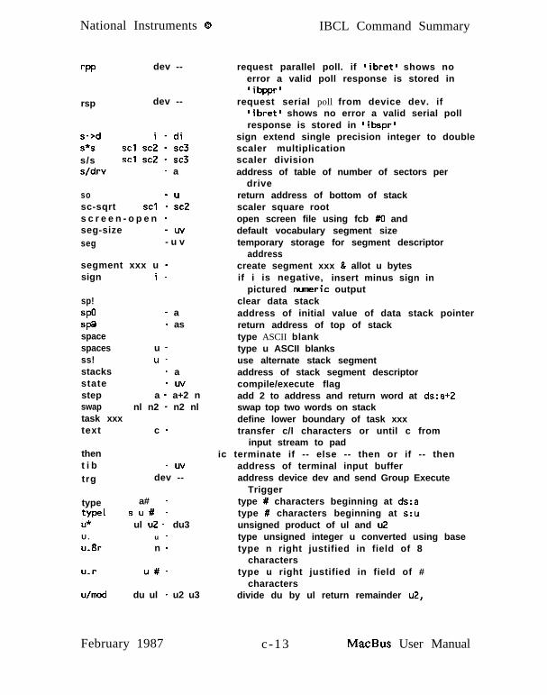
National Instruments 0 IBCL Command Summary
dev -- request parallel poll. if ‘ibret’ shows noerror a valid poll response is stored in‘ibppr’
rsp dev -- request serial poll from device dev. if‘ibret’ shows no error a valid serial pollresponse is stored in ‘ibspr’
s->ds*s SC1 sc5 1 ::3s/s SC1 SC2 - SC3s/drv - a
so - usc-sqrt SC1 - SC2s c r e e n - o p e n -seg-size -uvseg - u v
segment xxx u -
sign extend single precision integer to doublescaler multiplicationscaler divisionaddress of table of number of sectors per
drivereturn address of bottom of stackscaler square rootopen screen file using fcb #O anddefault vocabulary segment sizetemporary storage for segment descriptor
addresscreate segment xxx & allot u bytesif i is negative, insert minus sign in
pictured nuaeric outputsign
sp!
spasp@spacespacesss!stacksstatestepswaptask xxxtext
thent i b
trg
type
i -
- a- as
u -u -
- a-uv
a - a+2 nnl n2 - n2 nl
c -
-LNdev --
a# -type1 su# -U* ul u2 - du3U. u -u.Br n -
u.r u#-
U/mod du ul - u2 u3
February 1987
clear data stackaddress of initial value of data stack pointerreturn address of top of stacktype ASCII blanktype u ASCII blanksuse alternate stack segmentaddress of stack segment descriptorcompile/execute flagadd 2 to address and return word at ds:a+2swap top two words on stackdefine lower boundary of task xxxtransfer c/l characters or until c from
input stream to padic terminate if -- else -- then or if -- then
address of terminal input bufferaddress device dev and send Group Execute
Triggertype # characters beginning at ds:atype # characters beginning at s:uunsigned product of ul and u2type unsigned integer u converted using basetype n right justified in field of 8
characterstype u right justified in field of #
charactersdivide du by ul return remainder u2,
c-13 MacBus User Manual

IBCL Command Summary 0 National Instruments
u< ul LIZ - funtil f -
user-base - a
update
use- list sd -user xxx u -v a r i a b l e x x x -vectors name n -voc- link - uv
vocabulary xxx -
W%
waitwaitwarningwhile
widthword
word- seg
wrqs
wrt
xor
E
n -
dev maskmask ---uv
f -
- uvc - a
al - a2
dev mask n
dev L c --
ul u2 - u3
Ccompi l e l x x x -
1
MacBus User Manual
quotient u3true if ul is below u2
ic terminate begin -- until loop repeat untilflag is true
constant: address of base of user variablearea
mark most recently referenced blockaltered
use alternate list segmentdefine new user variable xxx at offset udefine variable xxxcreate execution vector tableaddress of voc-link field in most
recently defined vocabularycreate vocabulary xxx and allot
segment xxx-seg of size seg-sizeto contain it
append word n to latest machine codedefinition
wait for selected GPIB events to occurwait for selected GPIB events to occurflag to suppress non-fatal errorscontinue begin -- while -- repeat
loop until f becomes falsethen continue after repeat
nunber of valid characters for nameaccept characters from input stream until c
or end of line transfer to ds:areturn segment descriptor address for
vocabulary with vocabulary descriptor atds:al
- wait for device dev to request service witha positive response such that the logicalAND of the response and masked = nbd.if ‘ibret’ shows no error a valid poll isstored in ‘ibspr’
write c bytes from long address L to devicedev
exclusive or of ul and u2
i end compilation mode, begin execution modeic force compilation of following word
remainder of line (to cr) is comnentset compi tat ion mode
c - 1 4 February 1987

APPENDIX D - IBCL TUTOlXICAL
INTRODUCTION
IBCL is the programming language that programs the NEC-V50 inthe MacBus expansion box. The IBCL interpreter resides in theMacBus and serves as both the native language and the operatingsystem of the box. The users of IBCL include OEMs who havecustom applications for MacBus, and experienced users who wishto access the full power of the onboard NEC-V50. Most userswill use the language interface libraries for their programming.
THE LANGUAGE
Tutorial, is a brief tutorial which takes you through most of thehighlights of the language. It uses the MacBus utility, IBCLWindow.
IBCL opens up all the resources of the MacBus interface to asingle user. For this reason it is recommended that whendeveloping applications with IBCL, no other GPIB processesshould be active.
February 1987 D - l MacBus User Manual

IBCL Tutorial 8 National Instruments
TUTORIAL
Starting the IBCL Window
In the following examples, what you type is in boldface, what thecomputer displays is in italics. The character ‘ q ’ means press thespacebar. The symbol ‘ <CR> ’ means press the carriage-return.
Start the IBCL Window by double-clicking the IBCL Windowicon.
IBCL Window
Refer to SECTION TEN - IBCL WINDOW for more informationon the IBCL Window utility.
The IBCL operating system responds with ok after a successfuloperation. Type <CR> a few times to make sure IBCL is there.IBCL should respond:
okokokok
IBCL uses a push-down stack to store the numbers entered. Tryentering the following. Be sure to put a space after everycharacter, including the dots (.).
MacBus User Manual D-2 February 1987
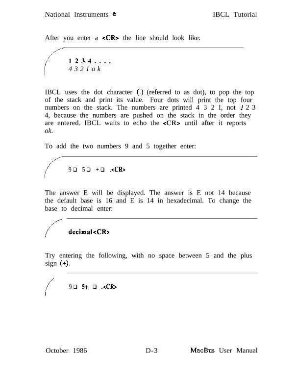
National Instruments @ IBCL Tutorial
After you enter a <CR> the line should look like:
1234....4 3 2 1 o k
IBCL uses the dot character (.) (referred to as dot), to pop the topof the stack and print its value. Four dots will print the top fournumbers on the stack. The numbers are printed 4 3 2 I, not I 2 34, because the numbers are pushed on the stack in the order theyare entered. IBCL waits to echo the <CR> until after it reportsok.
To add the two numbers 9 and 5 together enter:
/;/9 q 5 q + q .<CR>
The answer E will be displayed. The answer is E not 14 becausethe default base is 16 and E is 14 in hexadecimal. To change thebase to decimal enter:
f/decimal<CR>
Try entering the following, with no space between 5 and the plussign (+).
/9 q 5+ q .<CR>
October 1986 D-3 MacBus User Manual

IBCL Tutorial
IBCL will respond:
0 National Instruments
//5+ : Not recognized
IBCL thinks in terms of words, where a word is any sequence ofcharacters separated by a space or a <CR>. Since there is nospace between the 5 and the +, IBCL thinks 5+ is one word. Notethat since there was an error, IBCL did not report ok.
If you type . (dot) you will get the message:
* Short stack. .
Short stack means that there are no numbers on the stack. Thereason is that IBCL clears the stack after an error.
Defining New Words
The real power of IBCL is its ability to quickly add new words toits dictionary. The dictionary is the list of IBCL functions.
Define a new word called 3add, which will add together the topthree numbers on the stack together. Enter:
f: q 3add q + q + q ;<CR>
Now, you try it:
5 q 6 q 7 q 3add q .<CR>18 ok
MacBus User Manual D-4 October 1986

National Instruments 0 IBCL Tutorial
IBCL returns the answer 18 (decimal).
A new word is defined with a sequence starting with a colon (:).The first word after the colon is the name of the new word. Theremaining WONTS, up to the semicolon (;) are the body of the newword.
Now make a new word, 3addshow, which adds the top threenumbers on the stack and prints out the result. Enter:
T : @3addshowo.“oThe@answeroiso”o3addn.q~CR~
Now, you try it:
i
3 q 4 q 5 q 3addshow<CR>The answer is 12 ok
Notice that 3addshow uses 3add, which is now part of thedictionary. The word .‘I will print out the characters up to thenext ” exactly as they are entered.
Loops and Conditionals
Make a new word doline which will loop 5 times and print out themessage line i, where i is the loop count. Enter:
/: q dolineo5o0cdoocro.“oline”oio.oloopo;<CR~
October 1986 D-5 MacBus User Manual
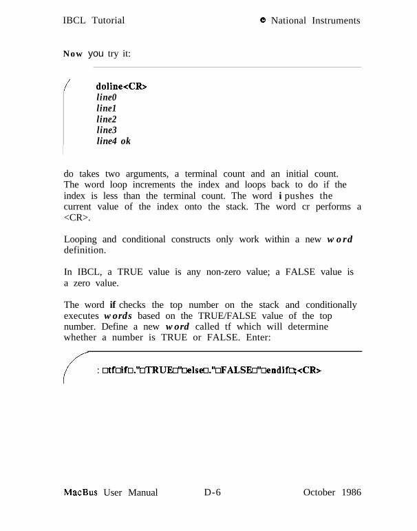
IBCL Tutorial 8 National Instruments
Now you try it:
/ doline<CR>line0line1line2line3line4 ok
do takes two arguments, a terminal count and an initial count.The word loop increments the index and loops back to do if theindex is less than the terminal count. The word i pushes thecurrent value of the index onto the stack. The word cr performs a<CR>.
Looping and conditional constructs only work within a new worddefinition.
In IBCL, a TRUE value is any non-zero value; a FALSE value isa zero value.
The word if checks the top number on the stack and conditionallyexecutes words based on the TRUE/FALSE value of the topnumber. Define a new word called tf which will determinewhether a number is TRUE or FALSE. Enter:
I : Mfoifo.“~RUEo”oeIseo.“oFALSEo”wndifo;<CR>
MacBus User Manual D-6 October 1986

National Instruments 0
Now you try it a few times:
IBCL Tutorial
/-1 q tf<CR>TRUE ok0 q tf<CR>FALSE ok-1 •I tf<CR>TRUE ok9 q 9 q + q tf<CR>TRUE ok9 q 9 q - q tf<CR>FALSE ok7 q 4 q = q tf<CR>FALSE ok7 q 4 q > ci tf-&R>TRUE ok
In the second to last example, the equal sign (=) tests the equalityof the top two numbers on the stack. In the last example, thegreater than sign (>), tests whether the second number on thestack is greater than the top number on the stack.
Stack Words
Sometimes the order of numbers on the stack is not what youwant, or sometimes you need to check a value on the stackwithout losing it. There are several stack words that fix theseproblems.
Enter:
;’ 1 q 2 q 3 q 4 q swap q . q . q . q .<CR>
October 1986 D-7 MacBus User Manual

IBCL Tutorial 0 National Instruments
The result will be 3 4 2 I because swap swappedthe top two numbers on the stack. Enter:
2 •I dup •I . q *<CR>
The result will be 2 2 because dup duplicated the top number onthe stack.
Another stack word, drop, drops (pops) the top number from thestack.
More Looping
With the words encountered so far, we can explore some of themore complicated looping structures.
Enter the following three lines:
: wq4urlupc4o=n;<CR>: q ndeco.“ogoingo”olo-oeq4@<CR>: q beg1dlobeginondecountilo.“ogoneo”odropo;~CR>
Now you try it:
( beg1 <CR>going going going gone ok
MacBus User Manual D-8 October 1986

National Instruments e IBCL Tutorial
The word begin marks the start of a non-iterated loop. untilchecks the first number on the stack, which is the result fromndec, and if it is FALSE loops back to the begin statement-thatis, it loops until ndec returns TRUE.
ndec prints out the string “going ” then subtracts one from the topnumber on the stack. It then calls eq4 which will return aTRUE/FALSE value indicating whether the top number of thestack is equal to 4.
eq4 duplicates the top number on the stack and compares it to 4.The number must be duplicated because the compare with 4 willpop the top two numbers off the stack when it does the compare.
After the begin . . . until the number 4 was still on the stack; thedrop gets rid of it.
October 1986 D-9 MacBus User Manual

IBCL Tutorial @ National Instruments
Forgetting
If you have tried reentering a word definition, you have seen themessage:
xxxx : Isn’t unique
IBCL does not replace a previous word with the new one, itremembers both, but uses the most recently defined. To revertback to the previous version use forget. Try entering thefollowing sequence:
/ : 0 ver 0 .‘I q version q 1 q ” q ;<CR>ok: 0 ver 0 .‘I q version •I 2 q ” q ;<CR>ver : Isn’t unique okver<CR>version 2 okforget ver<CR>okver<CR>version I okforget vertCR>okver<CR>ver : Not recognized
The last forget removed the original definition. forget removesthe requested word and all words that were defined since thatword.
MacBus User Manual D-10 October 1986

National Instruments Q IBCL Tutorial
GPIB Functions
If you do not have GPIB devices handy omit this section. To usea GPIB, device you must have previously configured one using theutility IBCONF. For this example, assume there is a digitizernamed dig already configured. Before you can use dig you mustopen it:
f ibfind q dig<CR>
If no error was reported dig is now ready for use. To clear devicedig, enter:
//dig q clr<CR>
All device functions require the name of a device as their firstargument. To write a command to device dig enter:
T dig q ” q cap13;25” q wrt<CR>
The double quote character (‘I) creates a buffer with the text‘cap13;25’ in it. It leaves on the stack the long address of thebuffer and its count. These arguments are in the correct order forthe wrt function.
Exiting the IBCL Window
To exit the IBCL Window, type “stop”. This returns you to theMacintosh Plus Finder.
October 1986 D-11 MacBus User Manual

APPENDD( E - SCALED IY-UMB-
The NEC 72191 floating point processor is an optional feature onMacBus, so every user will not have one. IBCL provides asoftware floating point capability for the user who does not have acoprocessor. This section documents this capability.
To use the software floating point facility, the utility file SCALERmust be downloaded to MacBus. Do this using the IBCLloadutility provided on your distribution disk or using the IBCLloadfunction in the Megamax C MacBus Support Library (purchasedseparately). The file contains the definitions of words to supportsoftware floating point. This section describes these words.
An IBCL software floating point number is stored on the stack inan easy-to-manage format. The mantissa is stored as a doubleprecision (i.e., 32 bit) number and the exponent is stored as asingle precision (16 bit) number. When such a number is on topof the stack, the exponent is on top and the mantissa is beneath it.For example, if you give IBCL the following input:
32. 5
a floating point number representing 32.0E+5 will be on the stack.Note that the decimal point forces this to be a double precisionnumber.
Addition and subtraction using floating point is significantlyslower than integer double word addition. If the magnitude ofnumbers is limited, a fixed scaling factor and normal double wordarithmetic will be much faster. For instance, financial calculationsmight need to be done in tenths of a cent. If the maximum dollarvalue computed at any one time can be kept below $2,147,483.64there is no need for floating point of any kind. This range can bedoubled for unsigned numbers.
We call this data type scaled because it is not a true binaryfloating point. True binary would require a base two exponent.
February 1987 E - l MacBus User Manual

Scaled Numbers 63 National Instruments
Addition and subtraction using base 10 floating point instead oftrue binary is slower. However, converting numbers to truebinary and back to display format is even slower. Using scaleddecimal is a good compromise if the average number of additionsand subtractions per number is not large.
A scaler is entered onto the stack from the keyboard by firstentering a double word number and then retrieving the exponentfrom dpl. dp can be used to retrieve the exponent. If used in acolon definition, it also normalizes the number.
12345.678 dp . d.
: test 12345.678 dp ; test . d.
The number entered must fit on one line but may have anynumber of digits and the decimal point may be located anywhere.The number stored in dpl is the power of ten by which the doubleword integer must be multiplied to produce the original value.Therefore, if the number is too large or too small to be easilyentered, it can be entered in “scientific” notation. Suppose wewant to enter 5.76 * 10 ** 339 :
5.76 dp 339 +
This produces the same number that would have been produced ifwe could have typed 576 followed by 337 zeroes. Similarly, 5.76 *10 ** -339 can be entered as:
5.76 dp 339 -
Very large and very small numbers can be displayed in a similarnotation:
rot rot d. . ” *,o**,, .
This displays 576 * lo** 337 or 576 * lo** -341. Usually wewould use .‘I e” instead of .I’ * 10 ** ” to be consistent withconventional computer abbreviations.
MacBus User Manual E-2 February 1987

National Instruments 0 Scaled Numbers
The usual variable, constant, store, and at words are provided, andassume the stack items covered above.
nnn.nnn dp x-constant namescaler nameSC!SC@
Given two scaled values (6 words) on the stack, we can performaddition and subtraction.
sc+ ( scaler1 scaler2 -- scaler3 )sc- ( scaler1 scaler2 -- scaler3 )
Multiplication and division require a scaled value on the stackwith a simple signed integer on top of the stack. This provides anefficient multiplication and division for cases such as some dollaramount being multiplied by the total number of units, or anaverage of a sum of entries.
sc* ( scaler1 integer -- scaler2 )SC/ ( scaler1 integer -- scaler2 )
A pair of scaled values on the stack can also be multiplied ordivided.
s*s ( scaler1 scaler2 -- scaler3 )s/s ( scaler1 scaler2 -- scaler3 )
The square root of a scaled value can also be calculated. Onlyfour decimal digits will be significant. If the scaled value isnegative, the square root of its absolute value will be returned.
sc-sqrt ( scaler1 -- scaler2 )
MEMORY
ccc@ At and Store are prefixed by the desired in memoryccc! data format. The address is on the IBCL data stack
October 1986 E-3 MacBus User Manual

Scaled Numbers @ National Instruments
as usual, and is dropped after the command. The sourceor destination of the data is the IBCL stack. Validforms are:
i16&l i32@ i64@ r32@ r64@ r80@ bed@ ( addr - :: -x)i16! i32! i64! r32! f-64! r80! bed! ( addr - :: x - )
Be certain that the memory allotted for the variable names usedis sufficient. bed@ bed! r80@ and r80! all require five wordsfor each memory location. (10 bytes)
variable r80-var 8 allot (2 allotted automatically)
STACK
fdup ( *-. . r80 -- r80 r80 )fdrop ( :: r80 -- )fswap ( :: y x -- x y )f o v e r (:: yx -- yxy)frot ( :: 2 Y x -- y x 2)
COMPAReISON
Comparisons follow the usual IBCL convention of comparing thesecond number on the stack to the one on top, popping both, andreturning a flag on the data stack. The numbers being comparedare both on the NEC 72191 stack.
f< f= f> ( -- flag :: y x -- )fO< fO= fO> ( -- flag :: x -- )
fmax ( :: y x -- maximum )fmin ( :: y x -- minimum 1
fxam ( -- status :: x -- x 1
Refer to assembler for definition of Status word.
MacBus User Manual E-4 October 1986

National Instruments 8 Scaled Numbers
CONSTANTS
The following words place the value of a constant on the fstack.
f=Of=lf=pif=l2(10)f=lZ(e)f=log(2)f=ln(Z)
( : : - - 0 1( : : - - 1 )( :: - - pi 1( :: - - log of 10 base 2 )( :: - - logof e b a s e 2 )( : : - - log of 2 base 10 )( :: - - logof 2 b a s e e )
MATH
Math functions follow the usual IBCL conventions where the topnumber on the stack is subtracted from or divided into the second,both arguments are dropped and the result is returned. For unaryfunctions, the result replaces the argument.
Note: Stack order of arguments is determined by standard IBCLconventions, not NEC 72 19 1 conventions.
Unary_----fsqrt ( :: x -- square root of x )
-0 <= x <= +infinityf**2 ( :: x - -fabs ( :: x - -fnegate( :: x - -
x*x )absolute value of x )-x )
frndint ( :: x - - x rounded to integer toward 0 )This word can be used to convert very small (unnormal)numbers to 0. The high level transcendental functionsincluded in IBCL perform this function whenevernecessary.
Binary__-_-_
f+ ( :: y x -- y+x )
October 1986 E-5 MacBus User Manual

Scaled Numbers Q National Instruments
f- X -- y-x )
f* ii; ; x -- y*x )f/ ( :: y x -- y/x )fmod ( :: y x -- remainder(y/x) )
fmod is a floating point modulo operation wherex is divided into y an integral number of times.The remainder is returned on the fstack, whilethe lowest order 3 bits of the quotient arereturned in the NEC 72191 Status word.( see fprem. )
TRANSCENDENTAL
The acceptable range for arguments for transcendental functionshas generally been extended to the full number line with fourexceptions:
1. Never use infinity as an argument.
2. The absolute value of an effective power must be less than2**15.
3. Do not use zero as the argument of a log
4. Do not use an unnormal as an argument.
Exponentials- - - - - - - - - - - -fscale ( :: y sf -- y*2**sf )
function.
Scale y by scale factor sf, which is rounded to an integertoward 0. If sf is between plus and minus 1, it must beexactly 0.-32768 <= sf < 32768
f2** . .( x--flo** ( II x
2**x ) abs(x) < 2** 15- - lO**x ) abs(x) < 2**15/log2(10)
f** ( :: y x -- y**x ) abs(x) < 2**15/log2(y)0 < y c infinity
MacBus User Manual E-6 October 1986

National Instruments 0 Scaled Numbers
f*12t ( :: x -- x * log2(10) )f*12x ( :: y z -- y * log2(z) )
0 < z < infinity -infinity < y < infinity
Logarithms_---------f2log ( :: x -- log2 (x) ) 0 < x < infinityflnflog ii; ;
-- 1n.e (x) ) 0 < x < infinity-- loglO ) 0 < x < i n f i n i t y
Trigonometric_____________The trigonometric functions expect or return an angle in radians.The magnitude of the angle should be a normal number less thaninfinity but is not otherwise restricted.
ftriangle ( :: x -- adjacent opposite )
ftanfsinfcos
This is the root word from which tangents, sines, andcosines are calculated. It returns the signed lengthsof the opposite and adjacent sides of a right trianglewith radius approximately 1.5 generated by the angle.The remaining forward trigonometric functions canbe easily determined from these sides.
;;; ;-- tan(x) )-- sin(x) )
( :: x -- cos(x) )
cosec x = 1 / sin xset x = 1 / cos xcot x = 1 / tan x
farctan ( :: x -- angle with tangent equal to x )
CONVERSIONS
These words move either double word integers or scaled decimalnumbers between the IBCL data stack and the NEC 72191 floating
October 1986 E-7 MacBus User Manual

Scaled Numbers 0 National Instruments
point stack. If the top of the NEC 72191 stack does not contain anormalized number or zero for conversion to a scaler, ameaningless number will be produced. You can check for a validnumber with ftype if presence of a valid number cannot beguaranteed.
>>f ( double-nmber -- :: -- treal )f>> ( -- double-nunber :: treal -- )sc>>fI ( double-number scale - - : : - - t real )f>>scI ( - - d o u b l e - n m b e r s c a l e : : t r e a l - - )
TYPE CHECKING
ftype ( -- type :: x -- x )Places a word on the IBCL data stack summarizing thecharacteristics of the top word on the 72191 stack.A bit is set in this word for every applicablecharacteristic.
bit mask(hex) characteristic7 80 negative (sign bit set)6 40 empty5 20 not a number4 10 infinity3 08 normal, nonzero2 04 zero1 02 unnormal0 01 normal or zero
INPUT/OUTPUT
Numbers are input in scaled decimal format. Enter an integercontaining an appropriately placed decimal point, and follow withdpl @ to give the base 10 scale factor. This will enter the scaleddecimal number onto the IBCL data stack. It may then be movedto the fstack with f>>sc or stored in a scaler variable.
MacBus User Manual E-8 October 1986

National Instruments 0 Scaled Numbers
Integers can also be entered as either single or double integers andthen be moved to the fstack with f>>. Single integers must firstbe converted to double with s-Rd.
Four output words are included for scaled numbers. They expecta signed double integer on the IBCL data stack, with a decimalscale factor above it. The S C. version prints the number with thedecimal point in position. The se. version always places thedecimal point to the right of the first significant digit and followsthe number with e and the appropriate power of 10.
The SW and se.r version print a maximum number of digits rightjustified in a field of some minimum width. The number givenfor digits should be large enough to include the decimal point andthe sign. It does not include the e or the exponent for the se.rversion. The number is truncated to the maximum number ofdigits. If the field width is insufficient for the number, it isexpanded to hold the complete number.
double-number scale SC.double-number scale se.double-number scale max#digits min-field-width sc.rdouble-n&r scale max#digits min-field-width se.r
examples: .000123456 dpl @ SC. 0.000123456.000123456 dpl @ se. 1.23456E-4.000123456 dpl @ 7 14 sc.r 0.00012.000123456 dpl @ 5 14 se.r 1.234e-4
f=pi f>>sc SC. 3.14159265
NEC 72191 CONTROL
finit Initialize NEC 72191. (see finit.)
fldcw ( control-word -- )Load control word from data stack into NEC 72191.
fstcw ( -- control-word )Push current NEC 72191 control word onto data stack.
October 1986 E-9 MacBus User Manual

Scaled Numbers 0 National Instruments
fstsw ( - - s ta tus-word )Push current NEC 72191 status word onto data stack.
NEC 72191 Notes
If you overflow the NEC 72191 stack, you will lose more than justthe bottom elements of the stack. The NEC 72191 will mark thetop conflicting words of the stack empty as well. You cannot dropwords from the bottom of the stack by writing over them as thestack wraps around.
1. >>f 2. >>f 3. >>f 4. >>f 5. >>f 6. >>f7. >>f 8. >>f 9. >>f
f>> d. f>> d. f>> d. f>> d. f>> d. ) (empty) 8 7 6 5f>> d. f>> d. f>> d. f>> d. ) 4 3 2 (empty)
Several high level words need NEC 72191 registers as scratchregisters, reducing the total available for temporary storage.
f>>sc uses 4 NEC 72191 registers. The stack must contain nomore than five numbers when invoking f>>sc.
sc>>f f2** flo** f**f t r iangle ftan fs in fcos farctan use 3
f2log fin f l o g dgmrd rdmdg use 2
HIGH PRECISION I/O
If you are performing a significant amount of floating point I/Oor if you need more than nine decimal digits of precision, thescaled decimal I/O package will not meet your needs. The binarycoded decimal package, however, provides efficient I/O forfloating point numbers through 18 decimal digits. Significantfloating point functionality demands a NEC 72191, and the binarycoded decimal package works using the NEC 72191. It is meantto be used in conjunction with the 72191ibcl high level supportpackage or the 72191asm assembler extensions.
MacBus User Manual E-10 October 1986

National Instruments 0 Scaled Numbers
Do not be confused into thinking that this package limits you touse of binary coded decimal numbers. Binary coded decimal issimply an intermediate format for efficiently translating ASCIInumber strings and loading them onto the NEC 72191, or movingnumbers from the NEC 72191 to ASCII string format for output.Our BCD format also includes provision for a base ten exponentover the full NEC 72191 range. All numbers on the NEC 7219 1itself are in temporary real format. They may be transferred toand from system memory in any convenient format that isappropriate to the given number.
This package includes words to read and write binary codeddecimal strings and move up to 18 digits with a base 10 exponentto and from the NEC 72191. It requires the NEC 72191 chip andsome words from the 72191ibcl high level support package. Havethe host download the files 72191ibcl and bed, respectively. Seeyour host software reference manual for details.
Note: If you are just moving numbers off the NEC 72191 forstorage, the most time efficient conversion is integer, followed byreal and temporary real. The packed BCD form takes significantlylonger to convert and should be used primarily for I/O. Evendata files can often be written in one of the internal integer orreal formats if they contain data for further processing and arenot meant for direct human reading.
The NEC 72191 is an efficient means for processing floating pointnumbers - but if a job can done with single and double integersand simple arithmetic, use of the NEC 72191 will result in adecrease in performance.
The format for numbers to be read by the BCD package is fairlytypical, except that it does allow for the optional use of commas.
The input string format is: sdd,ddd.ddd,ddesdddd
s signs, optionale and exponent are optional. optional, right of number assumed if absent, all commas are ignored
October 1986 E-11 MacBus User Manual

Scaled Numbers 0 National Instruments
d decimal digit, leading zeroes permittedsignificant digits can be far before or after decimal
Some acceptable numbers are:
0 +o -0 123 0123 12E5-12.3E6 .00012+123.456E-700000,000,123,456123456789123456789123456789.12300000000000000000OOOOOOOOOOOOO.ElOO.000000000000000000000000000001234E123.000,000,000,000,000,012,345,678,912,345,678,9-OOO,,,, 00,0,,0123.456,,,E+97
Numbers are written in a similar format, except that commas arenever written and the sign of the exponent is always includedexplicitly. For positive numbers, a space is written instead of theplus sign.
The following pages describe the words which read, translate, andwrite floating point numbers.
bed-in ( -- #digits )
Read numeric string from input stream.Return number of significant digits read.The string is initially read to the pad buffer and theNEC 72191 format packed BCD representation is built belowthe pad buffer. The base 10 exponent is stored at pad.The 10 bytes below pad and the two at pad may be storedin a variable, but are usually loaded directly onto theNEC 72191 by bcd>>f.
Execution example: bed-in - 123456789.12e7
First text reads the string to pad, then $->bcd converts it. Notethat the base 10 exponent stored at pad is -2, since the packedBCD representation is viewed as an 18 digit integer. Stack return#digits (number of significant digits) is 11.
MacBus User Manual E-12 October 1986

National Instruments 0 Scaled Numbers
text:padOf 31 32 33 34 35 36 37 38 39 2e 31 32 45 35
$->bcd:pad
00 00 00 20 91 78 56 34 12 80 fe ff
bcd>>f ( -- :: -- r80 )
Load the packed BCD number stored below padand the base 10 exponent stored at pad onto thetop of the NEC 72191 stack. This is usually doneimmediately after placing the packed BCD numberwith bed-in or moving it to the pad region from avariable. If you have loaded pad from a variablethat retained fewer than all 18 digits, be sure to setthe remainder of the pad transfer area to zeroes.
Note: Execution of bcd>>f uses five NEC 72191 stackregisters. Using more than eight stack registers willdestroy both top and bottom word of the NEC 72191stack.
f>>bcd ( -- :: r80 -- )
Convert the top number on the NEC 72191 stack topacked BCD representation below the pad buffer,and a base ten exponent stored at pad. Be sureto reformat and write the number, or move itelsewhere, before using the pad buffer foranything else.
Note: Execution of f>>BCD uses 5 NEC 72191 stackregisters. Using more than 8 stack registers willdestroy both top and bottom word of the NEC 7219 1stack.
October 1986 E-13 MacBus User Manual

Scaled Numbers 8 National Instruments
bed->$. ( #digits -- pad )bed->$e ( #digits -- pad )
Reformat the packed BCD representation below pad andthe base 10 exponent at pad to an ASCII string and leavethe address of the pad on the stack. Only #digits of thepacked string are used. Zeroes will be used if more digitsare required before the decimal appears usingbed->$
For bed->$e the decimal always follows the first digit,and an e followed by the exponent follows after #digitdigits.
The preceding words are most often used in pairs:
bed-in bcd>>f and f>>bcd bed->$. count typeor f>>bcd bed->$e count type
MacBus User Manual E-14 October 1986

APPENXX F - USING LABVIEW WITHMAcBus
This appendix provides examples that show you how to useMacBus with LabVIEW running on the Macintosh Plus. LabVIEWis a Laboratory Virtual Instrument Engineering Workbench for theMacintosh Plus. LabVIEW provides a complete integratedenvironment for scientific test and measurement applicationsinvolving instrument control, data acquisition, data analysis, datadisplay, data management, and report generation. BecauseLabVIEW is a complete programming environment, it is also wellsuited to stand-alone applications involving scientific computation,modeling, and experimentation. LabVIEW provides you withinteractive graphics, and a new graphical programming languageresulting in a visual environment that is intuitive and easy to use,yet powerful and flexible enough for scientific applications.LabVIEW is functionally complete. Any application possible in aconventional programming language is possible in LabVIEW.
WHY USE LABVIEW WITH MACBUS?
As a programming environment, LabVIEW is far more intuitive,and far easier to use than a program written in conventionalprograms built from lines of textual code. In addition, LabVIEWis an interactive programming environment that allows you tobuild applications “bottom-up” in testing each piece along the way.With LabVIEW, you can test and build MacBus IBCL applicationsthat can later be sent from a conventional type of program.
October 1986 F - l MacBus User Manual

Using LabVIEW with MacBus @ National Instruments
WHY USE MACBUS WITH LABVIEW?
MacBus provides the Macintosh Plus user with three key assets:
. A high-speed, intelligent IEEE-488 interface that can beprogrammed in a high-level language.
l Since MacBus is a complete, stand-alone computer, MacBusprovides an attached processor to the Macintosh Plus that canrun applications in IBCL concurently with the Macintosh Plus,and thus concurrently with LabVIEW. You can offloadcomputational tasks from LabVIEW to the MacBus.
l MacBus is PC-AT hardware compatible, and provides you withthree unused PC-AT slots in which PC/XT/AT compatiblehardware may be placed. This hardware can then be controlledby IBCL and LabVIEW.
All of this means that you may interface the scientificprogramming environment of LabVIEW, to PC/XT/AT compatiblehardware and operate the hardware concurrently with LabVIEW.For a given application, you have the flexibility to select thehardware, decide how much of the application will run on MacBusunder the IBCL interpreter, and how much of the application willbe run in LabVIEW. In addition, the MacBus processor is able tointerpret 80186 machine code and thus applications can bedeveloped on the IBM PC/XT/AT with the appropriate IBCLlanguage interface, downloaded into the MacBus from theMacintosh Plus and called by IBCL. This means that existingassembly language drivers and routines can be ported to MacBus.(See MacBus Technical Reference Manual for specifications).
MacBus User Manual F-2 October 1986

National Instruments Q Using LabVIEW with MacBus
THE LABVIEW MACBUS INTERFACE
LabVIEW provides a built in set of instruments (LabVIEWterminology for graphical programs or subroutines) that allow youto access MacBus from LabVIEW with the same low-level supportas supplied by the advanced function routines presented in theMacBus Software Reference Manual (SECTION SIX A - MicrosoftBASIC or SECTION SIX B - Megamax C). You are able to sendIBCL command strings to MacBus and receive IBCL responsesfrom MacBus. You can also upload and download memory buffersto MacBus and poll the status of MacBus. The icons of theinstruments provided by LabVIEW are shown below.
String to MACBUS Download Memory MACBUS Poll
Figure F-l - LabVIEW/MacBus Interface Instrument Icons
String To MACBUS, String From MACBUS, Download Memory,Upload Memory, and MACBUS Poll perform the same functionsas string out, fout, dlm, ulm, and poll in the MacBus SoftwareReference Manual. These instruments are explained in detail inthe LabVIEW User Manual.
October 1986 F-3 MacBus User Manual

Using LabVIEW with MacBus 0 National Instruments
LABVIEW/MACBUS EXAMPLES
The remainder of this appendix assumes that you are familiar withthe use of LabVIEW and its terminology. The remainder of thisappendix shows instruments that National Instruments hasdeveloped for in-house use to run MacBus/LabVIEW applications.After reviewing these instruments, you should be able to buildyour own LabVIEW/MacBus applications.
Key IBCL Words - allot, ulm, dlm
Key LabVIEW Instruments - String To MACBUSString From MACBUSDownload MemoryUpload MemoryMACBUS Poll
The following three instruments are the building blocks of theremaining LabVIEW/MacBus interface examples. Theseinstruments are called respectively: done poll, ulm poll, and dlmpoll. They are built on top of the MacBus Poll instrumentprovided by LabVIEW. MacBus protocol requires that prior toexecuting any of the instruments, String To MACBUS, StringFrom MACBUS, Download Memory, and Upload Memory, youmust poll MacBus using the Poll MACBUS instrument in order tosynchronize with MacBus. The instruments presented belowperform the necessary polls.
MacBus User Manual F-4 October 1986

National Instruments 0 Using LabVIEW with MacBus
Done Poll
Done poll repeatedly executes the MacBus Poll instrument andexamines the MacBus Status bit vector array (which corresponds tofstat in the MacBus Software Reference Manual), until bit 0(done) or bit 5 (error) is set, at which time the instrumentcompletes and returns the error value (0 or 1). Subsequent toexecuting this instrument, you may execute the String ToMACBUS or the String From MACBUS instrument. The donepoll icon, connector pane, and connector pane controls are shownin Figure F-2. The done poll panel is shown in Figure F-3 and adiagram of the done poll instrument is shown in Figure F-4.
October 1986 F-5 MacBus User Manual

Using LabVIEW with MacBus 0 National Instruments
DONEclPOLL
I CON
CONNECTOR PANE1
CONNECTOR PANE CONTROLS
Figure F-2 - Done Poll Icon, Connector Pane, and Connector PaneControls
BacBus address I bret
=(TJ Ia et-t-m DONE
i berrMacEus 5 tatus
‘“-‘oGPIB S t a t u s
(loi b c n t
Figure F-3 - Done Poll Panel
MacBus User Manual F-6 October 1986

National Instruments 0 Using LabVIEW with MacBus
i bent
October 1986
Figure F-4 - Done Poll Diagram
F-7 MacBus User Manual

Using LabVIEW with MacBus 8 National Instruments
Ulm Poll
Ulm poll repeatedly executes the MacBus poll instrument andexamines the MacBus Status bit vector array (which corresponds tofstat in the MacBus Software Reference Manual), until bit 2(MacBus waiting for ulm) or bit 5 (error) is set, at which time theinstrument completes and returns the error value (0 or 1).Subsequent to executing this instrument, you may execute theUpload Memory instrument. The ulm poll icon, connector pane,and connector pane controls are shown in Figure F-5. The ulmpoll panel is shown in Figure F-6 and a diagram of the ulm pollinstrument is shown in Figure F-7.
MacBus User Manual F-8 October 1986

National Instruments 8 Using LabVIEW with MacBus
CONNECTOR PANE CONTROLS
Figure F-5 - Ulm Poll Icon, Connector Pane, and Connector PaneControls
IIlacBus address
tlacBus s t a t u s
110
Do hGPIB s t a t u s i bret
E r r o r Readyf o r ULH
October 1986
Figure F-6 - Ulm Poll Panel
F-9 MacBus User Manual

Using LabVIEW with MacBus @ National Instruments
ibcnt
& !Uaiting:for ULH
%f o r ULH
Figure F-7 - Ulm Poll Diagram
MacBus User Manual F-10 October 1986

National Instruments 6 Using LabVIEW with MacBus
Dlm Poll
Dlm poll repeatedly executes the MacBus poll instrument andexamines the MacBus Status bit vector array (which corresponds tofstat in the MacBus Software Reference Manual), until bit 3(MacBus is waiting for dlm) or bit 5 (error) is set, at which timethe instrument completes and returns the error value (0 or 1).Subsequent to executing this instrument, you may execute theDownload Memory instrument. The dlm poll icon, connectorpane, and connector pane controls are shown in Figure F-8. Thedlm poll panel is shown in Figure F-9 and a diagram of the dlmpoll instrument is shown in Figure F-10.
October 1986 F-11 MacBus User Manual
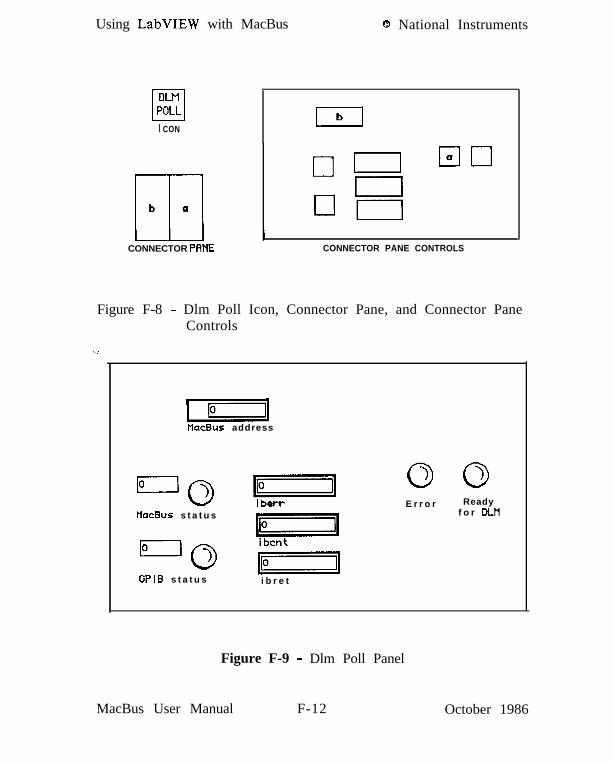
Using LabVIEW with MacBus 0 National Instruments
I CON
Elb a
CONNECTOR PRNEI
CONNECTOR PANE CONTROLS
Figure F-8 - Dlm Poll Icon, Connector Pane, and Connector PaneControls
.:
IVacBus address
tlacBus s t a t u s
- i65l
‘“‘0 hGPIB s t a t u s i b r e t
E r r o r Readyf o r DLH
Figure F-9 - Dlm Poll Panel
MacBus User Manual F-12 October 1986

National Instruments 8 Using LabVIEW with MacBus
i bent
p.clUaitinpffor LlLH
gfor DLH
October 1986
Figure F-10 - Dlm Poll Diagram
F-13 MacBus User Manual
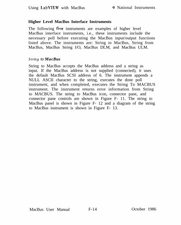
Using LabVIEW with MacBus 0 National Instruments
Higher Level MacBus Interface Instruments
The following five instruments are examples of higher levelMacBus interface instruments, i.e., these instruments include thenecessary poll before executing the MacBus input/output functionslisted above. The instruments are: String to MacBus, String fromMacBus, MacBus String I/O, MacBus DLM, and MacBus ULM.
String to MacBus
String to MacBus accepts the MacBus address and a string asinput. If the MacBus address is not supplied (connected), it usesthe default MacBus SCSI address of 6. The instrument appends aNULL ASCII character to the string, executes the done pollinstrument, and when completed, executes the String To MACBUSinstrument. The instrument returns error information from Stringto MACBUS. The string to MacBus icon, connector pane, andconnector pane controls are shown in Figure F- 11. The string toMacBus panel is shown in Figure F- 12 and a diagram of the stringto MacBus instrument is shown in Figure F- 13.
MacBus User Manual F-14 October 1986

National Instruments Q Using LabVIEW with MacBus
I CON
CAab
I ICONNECTOR PANE
b I
CONNECTOR PANE CONTROLS
Figure F-11 - String to MacBus Icon, Connector Pane, andConnector Pane Controls
MacBus Input String
Figure F-12 - String to MacBus Panel
October 1986 F-15 MacBus User Manual

Using LabVIEW with MacBus Q National Instruments
mMa&us address
HacBus I n p u t S t r i n g
III11234I npu t Error
Figure F-13 - String to MacBus Diagram
MacBus User Manual F-16 October 1986

National Instruments 8 Using LabVIEW with MacBus
String from MacBus
String from MacBus accepts the MacBus address as input. If theMacBus address is not supplied (connected), it uses the defaultMacBus address of 6. The instrument executes the done pollinstrument, and when completed, executes the String FromMACBUS instrument. The instrument returns the string and errorinformation from String to MACBUS. The string from MacBusicon, connector pane, and connector pane controls are shown inFigure F-14. The String From MACBUS panel is shown in FigureF-15 and a diagram of the String from MacBus instrument isshown in Figure F- 16.
Note: IBCL will not return a string unless the following IBCLcommand string is placed at the beginning of the first string sentto MacBus:
find iaemit ‘emit !
This string instructs IBCL to place its responses in the IBCLoutput buffer that is read by the String From MACBUSinstrument. It is only necessary to send this string once afterMacBus is powered on or reset. Strings returned from IBCL areterminated by the phrase “ok” and a carriage return, linefeed, andspace character.
October 1986 F-17 MacBus User Manual

Using LabVIEW with MacBus 0 National Instruments
I CON
CONNECTOR PANE CONNECTOR PANE CONTROLS
Figure F-14 - String From MacBus Icon, Connector Pane, andConnector Pane Controls
pqHacBus address
Ok
II 1 Output Error
MacEus Output String
Figure F-15 - String From MacBus Panel
MacBus User Manual F-18 October 1986

National Instruments @ Using LabVIEW with MacBus
tlacBus addressOutput String
Error
Figure F-16 - String From MacBus Diagram
October 1986 F-19 MacBus User Manual

Using LabVIEW with MacBus 8 National Instruments
MacBus String I/O
MacBus String I/O is a consolidation of the two aboveinstruments. It uses the same input and output variables as Stringto MacBus and String from MacBus and executes the sequence ofevents as if String to MacBus was executed followed by theexecution of String from MacBus. MacBus String I/O providesyou with a window to the IBCL interpreter in MacBus andthereby is useful for interactive programming in IBCL. You mayenter a string and when the Go icon is clicked, the string is sentto IBCL and any response returned.
Note: IBCL will not return a string unless the following IBCLcommand string is placed at the beginning of the first string sentto MacBus.
find iaemit ‘emit !
This string instructs IBCL to place its responses in the outputbuffer that is read by the String From MACBUS instrument. It isonly necessary to send this string once after MacBus is poweredon or reset. The MacBus string I/O icon, connector pane, andconnector pane controls are shown in Figure F-17. The MacBusstring I/O panel is shown in Figure F-19 and a diagram of theMacBus string I/O instrument is shown in Figure F-20.
MacBus User Manual F-20 October 1986

National Instruments 0 Using LabVIEW with MacBus
I CON
CONNECTOR PANEI I
CONNECTOR PFINE CONTROLS
Figure F- 17 - MacBus String I/O Icon, Connector Pane, andConnector Pane Controls
MacBus Input String
MacBus Output String
Figure F- 18 - MacBus String I/O Panel
October 1986 F-21 MacBus User Manual
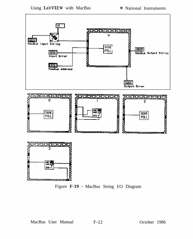
Using LabVIEW with MacBus 0 National Instruments
DONEPfl I
Output Strins
tlachs ad&err
liaJoutput Error
““rWE
~
11.
.I... . . . . _!!
Figure F-19 - MacBus String I/O Diagram
MacBus User Manual F-22 October 1986

National Instruments 8 Using LabVIEW with MacBus
MacBus DLM
MacBus DLM accepts the MacBus address, the information to bedownloaded, and a binary control as input. If the MacBus addressis not supplied (connected), it uses the default MacBus address of6. The information to be downloaded is handled in LabVIEW asif it were a string, however it is treated as binary information inMacBus. This “string” may contain any type of binary informationsuch as the contents of a file, or a previously uploaded buffer.The binary control controls whether or not the buffer is reversedas it is downloaded. Prior to downloading to MacBus, you mustallocate a buffer in MacBus to download to. This is done in IBCLby using the allot word or related words. The syntax of allot is:
n allot bufname
where II is the size of the buffer to be allocated, and bufname,when subsequently used, will cause the buffer segment (i.e.,paragraph number) to be pushed onto the stack. (See IBCL HeapManagement Words paragraph in Section Three of this manual).Before using MacBus DLM, a string must be sent to the MacBusthat executes the word dlm which instructs IBCL to prepare for adownload (See IBCL SCSI Interface Words paragraph in SectionThree of this manual). The word dlm requires that the segment,offset and length of the buffer be on the stack. For example:
20 allot MyownBuff MyownBuff 0 20 dlm
allocates a 20 byte buffer named MyownBuff and instructs IBCL todownload 20 bytes and store them at the address MyownButXOOOO.After this string is sent, the MacBus DLM instrument may beexecuted.
October 1986 F-23 MacBus User Manual

Using LabVIEW with MacBus 0 National Instruments
The MacBus DLM instrument executes the dlm poll instrument,and when completed, executes the Download Memory instrument.The instrument returns error information from Download Memory.The MacBus DLM icon, connector pane, and connector panecontrols are shown in Figure F-20. The MacBus DLM panel isshown in Figure F-21 and a diagram of the MacBus DLMinstrument is shown in Figure F-22.
MacBus User Manual F-24 October 1986

National Instruments 0
I CON
, ,
Id IC aHb
CONNECTOR PANE
Using LabVIEW with MacBus
CONNECTOR Pf3NE CONTROLS
Figure F-20 - MacBus DLM Icon, Connector Pane, and ConnectorPane Controls
~~tlacBus address
LoDownload Error
1Buffer to Download
.::.i;i;\
:::::iiiji;:>i:;::.:.:.:Reverse
October 1986
Figure F-21 - MacBus DLM Panel
F-25 MacBus User Manual

Using LabVIEW with MacBus Q National Instruments
pq . . .. . . . 1. . . . . . . . . .Reverse
_I=[Download Error
._
Figure F-22 - MacBus DLM Diagram
MacBus User Manual F-26 October 1986

National Instruments @ Using LabVIEW with MacBus
MacBus ULM
MacBus ULM accepts the MacBus address, the upload count and abinary control as input. If the MacBus address is not supplied(connected), it uses the default MacBus address of 6. The uploadcount specifies how may bytes will be uploaded from MacBusMemory. The binary control controls whether or not the buffer isreversed as it is uploaded.
Before using MacBus ULM, a string must be sent to the MacBusthat executes the word ulm which instructs IBCL to prepare for anupload (See IBCL SCSI Interface Words paragraph in SectionThree of this manual). The word ulm requires that the segment,offset, and length of the memory buffer to be uploaded be on thestack. For example:
MyownBuff 0 20 ulm
instructs IBCL to upload 20 bytes from MacBus memorybeginning at address MyownBufiOOOO. After this string is sent,the MacBus ULM instrument may be executed.
The MacBus ULM instrument executes the ulm poll instrument,and when completed, executes the Upload Memory instrument.The instrument returns the uploaded information from MacBus ina string and error information from Upload Memory. Theuploaded information is handled in LabVIEW as if it were anASCII string even though it is actually a sequence of binary bytes.The string may be subsequently parsed and converted to asequence of numbers by LabVIEW. The MacBus ULM icon,connector pane, and connector pane controls are shown in FigureF-23. The MacBus ULM panel is shown in Figure F-24 and adiagram of the MacBus ULM instrument is shown in Figure F-25.
October 1986 F-27 MacBus User Manual

Using LabVIEW with MacBus 8 National Instruments
Figure F-23 - MacBus ULM Icon, Connector Pane, andPane Controls
Connector
pzqflacBus address
Upload CountReverse
Uploaded Buffer
Figure F-24 - MacBus ULM Panel
MacBus User Manual F-28 October 1986

National Instruments 0 Using LabVIEW with MacBus
HacBus address
Upload Count
~~....................................................
Figure F-25 - MacBus ULM Diagram
October 1986 F-29 MacBus User Manual

Using LabVIEW with MacBus 6 National Instruments
Applications of These Example Instruments
The instruments described above have been used in-house atNational Instruments to run LabVIEW/MacBus applications. Someof our specific applications are presented below.
MacBus String I/O was frequently used to interactively test IBCLcommand string applications. The strings were then automaticallyconstructed and sent by LabVIEW using LabVIEW’s stringprocessing instruments and the String to MACBUS instrumentinside a higher level instrument.
The MacBus DLM instrument was used to download an 8086machine code binary executable file which had been executed andlinked on an IBM PC into MacBus memory. This file containedsubroutines and drivers to operate a PC compatible card. Thedrivers and subroutines had been developed previously for an IBMPC/XT/AT application. All that was added was an assemblylanguage interface to IBCL (See the MacBus Technical ReferenceManual). The binary file was copied from an IBM PC onto aMacintosh diskette by one of the PC to Macintosh file transferpackages available on the market. The binary file was opened andread into a string by the LabVIEW file I/O instruments and thenpassed to the MacBus DLM instrument. Once the machine codewas downloaded, the routines were called by executing IBCLwords that transferred execution to the beginning of the code’sbuffer.
The MacBus ULM instrument was used to upload the contents ofa buffer of data that had been generated by a card running inMacBus. Once the buffer was uploaded, the string was convertedinto an array by LabVIEW for subsequent scientific processing inLabVIEW.
The examples and applications presented in this appendix are onlya few of the possibilities provided by LabVIEW and MacBus.You should now be able to take these examples and applicationideas and develop applications that will suit your needs.
MacBus User Manual F-30 October 1986

Product User Comment Form
National Instruments encourages you to give us comments on thedocumentation supplied with its products. This information helpsus provide quality products to meet your needs.
Did you find deficiencies? Please comment on the completeness,clarity, and organization.
Did you find errors? If so, please give page number, and adescription of the error.
Thank you for your help.
Name Title
Company Name
Number & Street
City State & Zip
Phone ( )-
Mail to: Technical PublicationsNational Instruments12 109 Technology BoulevardAustin, TX 78727-6204 MacBus UM