february - apps.dtic.mil · at the midpoint of each segment. let q ( ') denote the complex...
TRANSCRIPT
UNLIMITED DISTRIBUTION
I * National Defence Defense nationaleResearch and Bureau de rechercheDevelopment Branch et developpement
TECHNICAL MEMORANDUM 89/204"February 1989
Ln
WADAl: FORTRAN PROGRAM FORWAVE DIFFRACTION ANALYSIS -
VERSION 1
Samon Ando
DTICELECTEAPR11
Defence Centre deResearch Recherches pour laEstablishment Defense
Atlantic Atlantique
Canad
.. c -d pu& ljc r1 g "-" r'. €-,'~'rOn

DEFENCE RESEARCH ESTABLISHMENT ATLANTIC CENTRE DE RECHERCHES POUR LA DfFENSE ATLANTIQUEt S TC F R 2 G E RE F T
I O-T-

UNLIMITED DISTRIBUTION
I 1* National Defence Defense nationaleResearch and Bureau de rechercheDevelopment Branch et developpement
WADAI: FORTRAN PROGRAM FORWAVE DIFFRACTION ANALYSIS -
VERSION 1
Samon Ando
February 1989
Aporoved by L.J. Leggat Director/Technology Division
DISTRIBUTION APPROVED BY
D/TO
TECHNICAL MEMORANDUM 89/204
Defence ' Centre deResearch ,- Recherches pour laEstablishment , DdfenseAtlantic , Atlantique
Canad'a
m • • m m1
ABSTRACT
This technical memorandum describes the FORTRAN computer program WADA1 (WAveDiffraction Analysis-version 1), which calculates the pressure induced by the diffraction ofregular incident waves on arbitrary-shaped two-dimensional cylinders fixed in the free surfaceof deep water. Based on the source-distribution method, WADA1 solves the integral equationfor the linear diffraction problem by Franks close-fit method.
RtSUM]t
Le pr6sent rapport technique d6crit le programme FORTRAN WADA1 (analyse de la diffrac-tion des vagues, premi6re version) qui permet de calculer la pression induite par la diffractionde vagues incidentes reguli~res sur des cylindres a deuz dimensions et de formes arbitrairesfizes a la surface libre d'eaux profondes. En faisant appel a la mithode de distribution des
sources, le programme WADA1 rgsout l'equation int6grale du problime de diffraction liniaireau moyen de la methode de l'ajustement fin de Frank.
ii

TABLE OF CONTENTS
Pages
AB STRACT ii
NOTATION iv
I. INTRODUCTION 1
2. STATEMENT OF THE MAThiEMATICAL PROBLEM I
3. SOLUTION TECHNIQUE 2
4. IRREGULAR FREQUENCIES 4
5 DESCRIPTION OF INPUT 5
6. DESCRIPTION OF OUTPUT 6
7. CONCLUDING REMARKS 7
ILLUSTRATIONS 8
APPENDIX A: SAMPLE INPUT 11
APPENDIX B: SAMPLE OUTPUT 13
REFERENCES 17
Accesion For
Lv , : '' =ed 0]*~ I.
I . an/o r
.- .,,1i and/or
iii

NOTATION
a amplitude of incident wave
B breadth of cylinder at waterline
G Green function
9 gravitational acceleration
Ili influence coefficients
Im imaginary part of a complex variable
Kj integral of aG/an along S3 for field point located at the th node
k dummy variable for integration
n normal unit vector to S pointing out of fluid
nj normal unit vector to Sj; n, = (ni1 ,ni 2)
nil, n, 2 z- and y-components of n,
P, time-dependent incident-wave pressure (= pie- i' t)
PD time-dependent diffracted-wave pressure (= pve - iwt )
Pw time-dependent total wave-induced pressure (= PI + PD)P.V. Cauchy principal value
P1 complex amplitude of incident-wave pressure
PD complex amplitude of diffracted-wave pressure
Q source strength
Qj source strength for the jth segment S,
Re real part of a complex variable
S cylinder contour below calm-water line
Si ith segment of S
S length variable along S
T draft of cylinder
t time
U, normal velocity of incident wave at S,
z, y coordinates of a field point
z complex variable (= z + iy), or a coordinate
0wave direction relative to the z-axis
bi Kronecker delta function
rij integral of G along S for field point located at the i~h node
complex variable (= + iy7)
iv
complex conjugate of
1, rcoordinates of a source point
CB frequency parameter (= vB/2)
v wave number (= w 2 /g)
p mass density of fluid
time-dependent incident-wave potential (= pje - i wt)
IDD time-dependent diffracted-wave potential (= PDe-iw)
4w time-dependent total potential (= 4 i + D)
0b phase angle between wave-induced pressure and incident wave
OJ complex amplitude of incident-wave potential
VOD complex amplitude of diffracted-wave potential
w wave frequency
V gradient operator
Superscript
(in) mode of pressure excitation
n = 1 horizontal excitation (asymmetric about the y axis)
rn = 2 vertical excitation (symmetric about the y axis)
Subscripts
i,j indices for contour segments
n indices for irregular frequencies
V

1. INTRODUCTION
This echnical memorandum describes the FORTRAN computer program WADA1 (WAveDiffraction Analysis-version 1) developed as part of DREA's on-going research to analyzethe interactions of ocean waves with marine vehicles. WADA1 calculates the hydrodynamicpressure induced by an incident sinusoidal wave and diffracted wave on arbitrary-shaped two-dimensional cylinders fixed in the free surface of deep water.
WADA1 solves the linear diffraction problem by the source-distribution method. It usesthe Green function that is a particular fundamental solution of the two-dimensional Laplaceequation and directly satisfies the boundary conditions on the free surface, on the sea bottom,and at infinity. The amount of required input data is minimal since only the boundary conditionon the body surface remains to be satisfied; however, the computation of the Green functionand its gradient is complicated. Also the method fails to give a unique solution at "irregularfrequencies," but these usually occur outside the range of frequency of practical interest.
The mathematical formulation of the linear diffraction problem is described in Section 2.The solution technique adopted in WADA1, a simple collocation method originally used byFrank', is outlined in Section 3. Comments on the "irregular frequencies" are made in Section4. Descriptions of the input and output are given in Sections 5 and 6, respectively. Concludingremarks are given Section 7. Sample input and output are included in Appendices.
2. STATEMENT OF THE MATHEMATICAL PROBLEM
The water is assumed to be deep and inviscid, and its motion irrotational. The waveamplitude is assumed to be small compared with a characteristic length of the body, say, thehalf-breadth of the cylinder, so that linearization is valid. In Fig. 1, the Cartesian coordinates(x, y, z) are fixed to the cylinder, which is assumed to be of infinite length in the z-directionwith a uniform cross section. The xz-plane lies in the calm-water surface. The y-axis pointsvertically upwards. The origin is located at the midpoint of the breadth B of the cylinder atthe calm-water line. The cylinder contour below the calm-water line in the xy-plane is denotedby S. The direction of propagation of the incident wave, the sinusoidal wave of frequency W,is at an angle 8 to the z-axis.
In the linear diffraction problem, which WADA1 solves, the total wave potential Pw isseparated into the incident-wave potential '1'j and the diffracted-wave potential ID:
w (X, Y, 0 = 'PI(X,Y, t) + D (X,Y, t).- (1)
The incident-wave potential is given by
ZV(x,y, t) = pi(x,y)etWt (2)
with ga _,- vx sinV1(X ,Y) =_--e e (3)
where i = V/-T, t is the time, a is the amplitude of the incident wave, g is the gravitationalacceleration, and v = w 2 /g is the wave number. Here and in the following, it is to be understoodthat only the real parts of complex expressions are to be taken.
I

The diffracted-wave potential is assumed to be of the form,
t) (,Y,0= iD(,y)est (4)
where PD is the solution of the Laplace equation:
+2 D(X) - 0 in the fluid domain, y < 0 (5)ax
2 ay 2
and satisfies the following boundary conditions:
aOD_9y YD = 0 on the free surface, y = 0 (6)
Jrn _ - 0 on the sea bottom (7)
8 'PDlim {-- T iVPD} = 0 at infinity (radiation condition) (8)aO2D _ aIan - - an on the body surface S(x, y) 0. (9)an an
In Equation (9), a/a. = n • V denotes the derivative in the direction of n, the vectornormal to the surface and pointing into the body. Except for the body-boundary condition(9), the above boundary-value problem is identical to the strip-theoretical radiation problemin which the right-hand side of Equation (9) is replaced by the prescribed velocity of the bodysurface.
In oblique waves, V0D should depend on the z-coordinate as well as on the x- and y-coordinates, but the dependence of V0D on the z-coordinate is neglected in the two-dimensionalmathematical model (5)-(9). As a result, the diffraction pressure predicted by WADA1 isexpected to become less reliable as the direction of propagation of the incident wave deviatesaway from that of the beam wave towards those of the head or following waves, that is,1 - -+ ?r/2.
3. SOLUTION TECHNIQUE
A common scheme of solving the radiation and diffraction problems is the source-distribu-tion method using the Green function G(x, y; , 7) that defines a velocity potential at a fieldpoint (x,y) owing to a source of unit strength located at a point ( , 17). If the strength ofthe source is Q(C,t), then by the assumption of linearity, the velocity potential at (x,y) isG(x,y; rj)Q( ,tj). Using a Green function, the diffracted-wave potential (D(x,y) can beexpressed in terms of a distribution of sources of strength Q( , r7) on the immersed surface Sof the body under the calm water line; that is,
PD(X, Y) = f G(x, y; , Y7)Q( , n1)ds(C, 17). (10)
Implicit in Equation (10) is the dependence of OD on v, and 3.
2
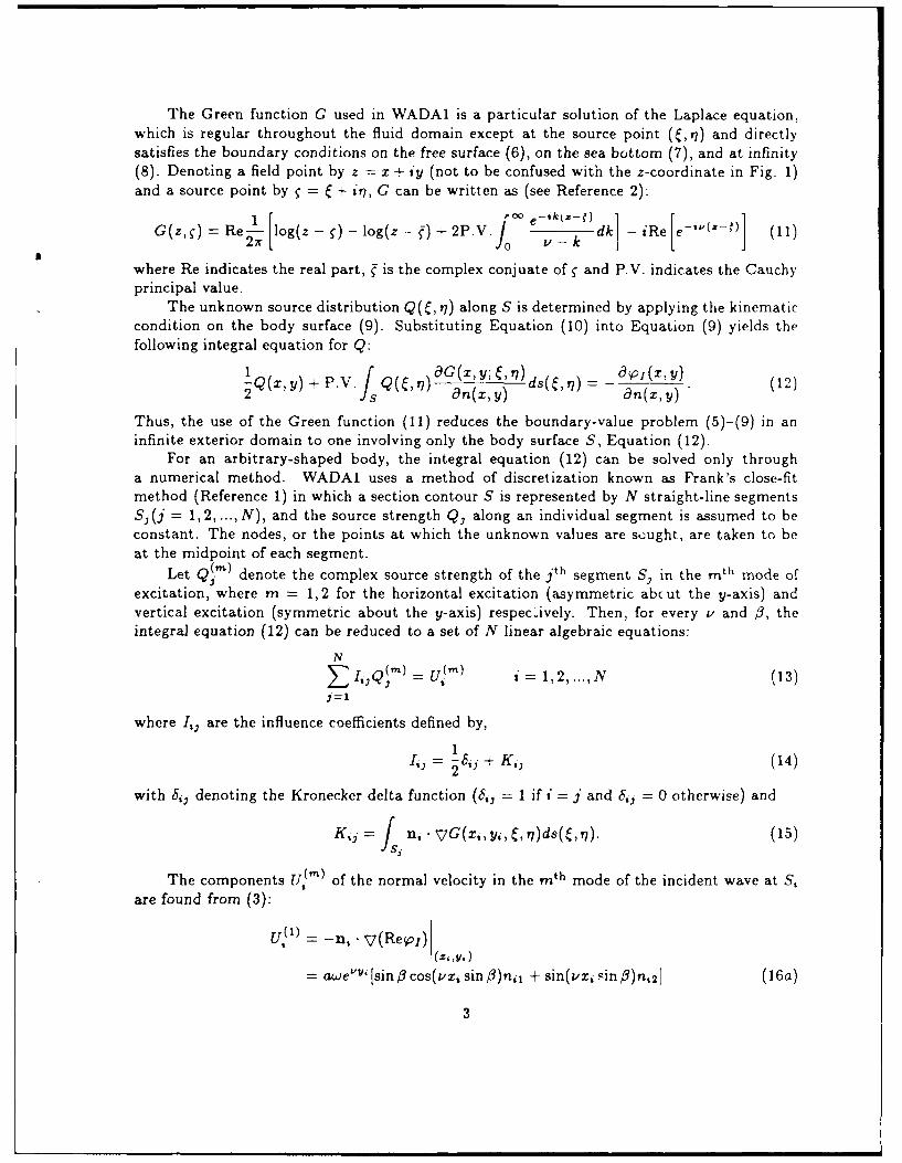
The Green function G used in WADA1 is a particular solution of the Laplace equation,
which is regular throughout the fluid domain except at the source point (C,tj) and directlysatisfies the boundary conditions on the free surface (6), on the sea bottom (7), and at infinity(8). Denoting a field point by z = x + iy (not to be confused with the z-coordinate in Fig. 1)and a source point by f = + st,, G can be written as (see Reference 2):
G(z,") = Re [log(z - -log(z- )+2P.V. -_ -dk iRe e (11)
where Re indicates the real part, is the complex conjuate of " and P.V. indicates the Cauchyprincipal value.
The unknown source distribution Q(C, Y7) along S is determined by applying the kinematiccondition on the body surface (9). Substituting Equation (10) into Equation (9) yields thefollowing integral equation for Q:
1Q(X, Y) + P. V.JQn) (9G(x, y; C v) ds ( t7) a aO I(X, Y) (22 fs an(X,y) a n(x,y) (12)
Thus, the use of the Green function (11) reduces the boundary-value problem (5)-(9) in aninfinite exterior domain to one involving only the body surface S, Equation (12).
For an arbitrary-shaped body, the integral equation (12) can be solved only througha numerical method. WADAl uses a method of discretization known as Frank's close-fitmethod (Reference 1) in which a section contour S is represented by N straight-line segmentsS,-(j = 1,2,...,N), and the source strength Qj along an individual segment is assumed to beconstant. The nodes, or the points at which the unknown values are scught, are taken to beat the midpoint of each segment.
Let Q( ') denote the complex source strength of the jth segment S. in the mth mode ofexcitation, where m = 1,2 for the horizontal excitation (asymmetric abcut the y-axis) andvertical excitation (symmetric about the y-axis) respecively. Then, for every v and 0, theintegral equation (12) can be reduced to a set of N linear algebraic equations:
Nj_.:.: ilm = ~ ) i 1, 2, ..., N 3
where Ij, are the influence coefficients defined by,
I = I i, + K,, (14)
with 8j, denoting the Kronecker delta function (6ij = 1 if I j and 6,, = 0 otherwise) and
K,3 = J i. VG(x,, y,, C, Y)ds( , j). (15)Ii
The components U, m) of the normal velocity in the mt h mode of the incident wave at S,
are found from (3):
UP( ) = - ,,. ( e j) ( i~
= awe ' [sin f cos(vxz sin O)n,, + sin(vzi sin /3)n,2] (16a)
3

UP2) = -in,. -v(Im 01)(,.)
= -iawe 'Y [sin .3 sin(vx, sin #)n 1l - cos(vz sin O)n,2]. (16b)
Here (z,, y,) are the coordinates of the node situated at the midpoint of the ith segment Si,and n, = (n. 1 , n, 2 ) is the normal unit vector to S, pointing out of the fluid. For the details ofevaluation of the influence coefficients Ij, see Reference 1.
By solving the algebraic equation system (13), the source density Q(i) can be deter-mined. Then the diffracted-wave potential WD(z,,y,) for S, is found by a direct quadraturevia Equation (10), so that
2
M= I
N 2Q,-r- (17)
=1 m=1
where
--- f^ G(xi,,yi, , P)ds , . (18)
The total periodic wave-induced pressure Pw is obtained from the linearized Bernoulli
equation, Pw --- for each node (x,,y,), with 4Dw given in Equation (1). Thus,
Pw (27, ,t) = PI (Xi,,,,t) + PDo(Xi,,,,t)
= [PI(Xi,y,) + PD(X,,y)]e= [Pw ]e'Oe - t (19)
where p, and PD-the complex amplitudes of the incident-wave and diffracted-wave pressures,respectively-are given by
= pgaevv, e-,1 'iz s (20)
PD,(X, Y) = ,WPPD(XiY) (21)
and IPwI and 4 are respectively the magnitude and argument, or the amplitude and phaseangle, of Pw.
4. IRREGULAR FREQUENCIES
Although physical problems always have unique solutions, the corresponding integral equa-tions do not have this property and break down at a discrete infinite set of wave frequenciescalled irregular frequencies. This phenomenon was first pointed out by John'. To determine
4

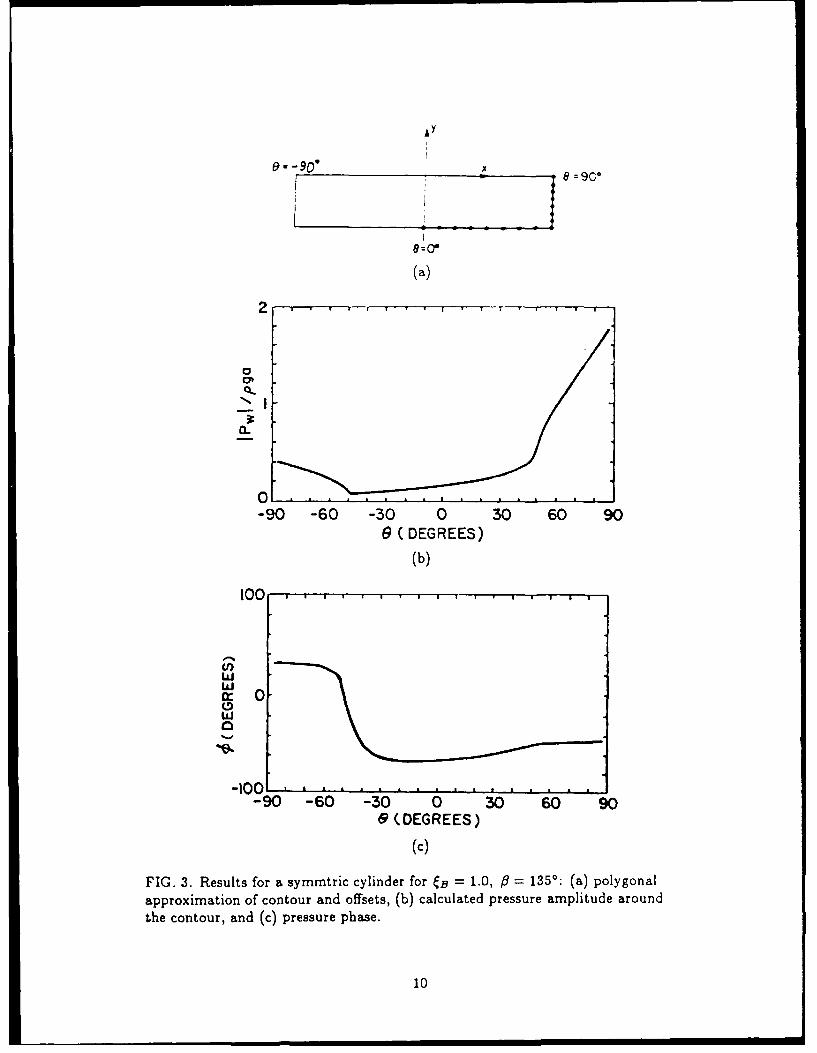
the irregular frequencies for an arbitrary-shaped body, it is necessary to solve the adjoint in-terior problem; see, for example, References 1, 3, and 4. (For a rectangular cylinder suchas shown in Fig. 3, the irregular frequencies can be expressed in a closed form as follows 1 :w, = /(n7rg/B) coth(nirT/B), where w, is the nth irregular frequency, n = 1,2,3,.... Here,B is the breadth and T is the draft of the cylinder.)
In practice, the influence-coefficient matrix (14), which approximates Equation (12) atdiscrete points, is often ill-conditioned even when w lies in the vicinity of the irregular fre-quencies. To guard against the occurrence of this phenomenon, the user should carry out thecomputation at a few extra frequencies in the neighborhood of the frequencies of interest tomake sure that no sudden discontinuities in the computed values occur when they are plottedagainst frequency. The user should disregard all results related to the discontinuities if theyshould occur.
5. DESCRIPTION OF INPUT
Data Set 1 (72 characters or less - FREE FORMAT)
TITLE - Brief description for identification purposes.
Data Set 2 (2 integers - FREE FORMAT)
ISYM - Control integer indicating whether the cross sectionpossesses a symmetry with respect to the yz-plane:
ISYM = 0 No left-right symmetry;ISYM = I Left-right symmetry exists.
NP - Number of offsets.
Note:
The number of segments should never be less than six ona half-section contour to ensure sufficient accuracy. (Thesize of a segment must be much less than the wavelengthand the local radius of curvature of the sectional contour.Also, because the source strengths are averaged over eachsegment, the segment sizes should be made smaller nearsharp corners.)
Data Set 3 (NP reals - FREE FORMAT)
(XA(I), I= 1,NP) - x-coordinates of the offsets.
(Note the remarks described in Data Set 4 below)
Data Set 4 (NP reals - FREE FORMAT)
(YA(I), I= 1,NP) - y-coordinates of the offsets.

Note:
(1) If ISYM = 0, then the first offset (XA(1),YA(1)) isthe intersection of the free surface and the body contourin the left half-section, and going along in a counter-clockwise direction, the last offset (XA(NP),YA(NP)) isthe intersection of the calm-water line and the bodycontour in the right half-section. The intersection of thecontour and the y-axis must be included as an offset.
(2) If ISYM = 1, then the first offset (XA(1),YA(1)) is theintersection of the y-axis and the body contour, and goingalong in a counter-clockwise direction, the last offset(XA(NP),YA(NP)) is the intersection of the calm-waterline and the body contour in the right half section.
(3) The computational algorithm in WADAI requires thatno two offsets in a half-section have identical vertical co-ordinates. For horizontal segments, this difficulty can beeasily overcome by giving insignificantly small "artificialslopes" to the segments; compare Fig. 3(a) and AppendixA(b).
Data Set 5 (1 integer - FREE FORMAT)
NOX - Number of wave frequencies.
Data Set 6 (NOX reals - FREE FORMAT)
(XIB(I), I= 1,NOX) - Values of the nondimensional frequency parameter:w2 B
, B- , where w is wave frequency, g the gravitation-2gal acceleration, and B the waterline breadth of the body.
Data Set 7 (1 integer - FREE FORMAT)
NOB - Number of wave directions.
Data Set 8 (NOB reals - FREE FORMAT)
(BETA(I), I= 1,NOB) - Directions f3 of wave propagation in degrees; see Fig. 1.
Sample input is included in Appendix A.
6. DESCRIPTION OF OUTPUT
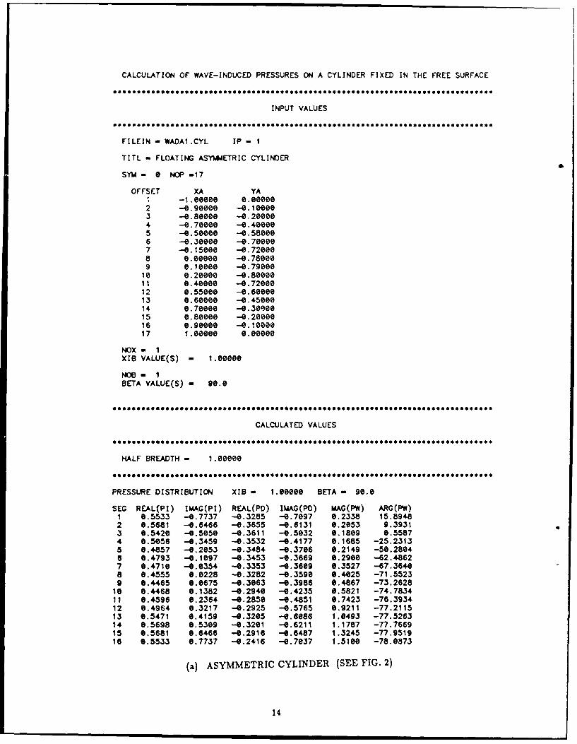
Appendix B shows an example of output corresponding to the sample input in AppendixA. The first part of the output is a printout of the input variables. They are followed by thevalues calculated by WADA1 for every combination of the wave frequency parameter CB (XIB)
6

and the wave direction 9 (BETA). The real and imaginary parts of the complex amplitudesof the incident-wave pressure pi (P1) and tine diffracted-wave pressure PD (PD) are printed,followed by the magnitude (MAG) IPw I and the argument (ARG) 0 of the total wave-inducedpressure Pw (PW) for each contour segment. Figures 2 and 3 show the plots of IPw I and 4.
7. CONCLUDING REMARKS
The FORTRAN program WADA1 was developed for use in fluid-structure interaction. prob-lems. Using the source-distribution method, WADA1 calculates the hydrodynamic pressureexerted by regular incident waves and diffracted waves on arbitrary-shaped two-dimensionalbodies fixed in the free suface of deep water. WADA1 requires a simple data input and in-volves a small number of unknowns. This is because the Green function used in WADAl isa particular fundamental solution that directly satisfies the boundary conditions on the freesurface, sea bottom, and at infinity, leaving only the body boundary "o be discretized.
Since the solution's dependence on the longitudinal coordinate is neglected in the two-dimensional mathematical model for WADA1, the reliability of WADAI's prediction is ex-pected to deteriorate as the direction of propagation of the incident wave deviates away fromthe direction of the x-axis.
7

, i"/ C'
,/ 'I
(a)
lY
/ B'
(b)
FIG. 1. Body geometry and definition of coordinates:(a) waterline plane and (b) cross section.
8

e~ a-0 - 90'x
8=0*
(a)
2
0N
0.
-90 -60 -30 0 30 60 90e (DEGREES)
(b)
5 0 . . ., - . . . . . . . .. .. .
50ww
w. -50
-1001-90 -60 -30 0 30 60 90
9(DEGREES)
(c)
FIG. 2. Results for an asymmtric c.linder for CB = 10, ft = 90': (a) polygonalapproximation of contour and offsets, (b) calculated pressure amplitude aroundthe contour, and (c) pressure phase.
9
lY
9:0"
(a)
2
0-
-90 -60 -30 0 30 60 90e (DEGREES)
(b)
100 . , ,
90 -60O 3 0 3 60 90& (DEGREES)
(c)
FIG. 3. Results for a symmtric cylinder for CB = 10, #9 1350: (a) polygonal
approximation of contour and offsets, (b) calculated pressure amplitude around
the contour, and (c) pressure phase.
10

APPENDIX A: SAMPLE INPUT
11

Data Set 1: FLOATING ASYIAETRIC CYLINDERData Set 2: e 17Data Set 3: -1. -0.9 -0.8 -0.7 -0.5 -0.3 -0.15 0.
0.1 0.2 8.4 0.55 6.6 8.7 8.8 e.9 i.eData Set 4: 8 -0.1 -0.2 -0.4 -0.58 -0.7 -0.72 -0.78
-0.79 -0.8 -0.72 -0.68 -0.45 -0.38 -0.28 -0.1e e.Data Set 5: 1Data Set 6: i.eData Set 7: 1Data Set 8: 98.
(a) AN ASYMMETRIC CYLINDER (SEE FIG. 2)
Data Set 1: FLOATING RECTANGULAR CYLINDERData Set 2: 1 16Data Set 3: 8. .156 .313 .469 .625 .781 .938 1.094 1.25 1.25 1.25 1.25
1.25 1.25 1.25 1.25Data Set 4: -1.ee -1.000875 -1.80075 -1.888625 -i.eee5 -1.e6375 -1.8025
-1.ee125 -1. -0.857 -0.714 -0.571 -0.429 -0.286 -0.143 0.Data Set 5: 1Data Set 6: 1.Data Set 7: 1Data Set 8: 135.
(b) A SYMMETRIC CYLINDER (SEE FIG. 3)
12
APPENDIX B: SAMPLE OUTPUT
13
CALCULATION OF WAVE-INDUCED PRESSURES ON A CYLINDER FIXED IN THE FREE SURFACE
INPUT VALUES
FILEIN - WADA1.CYL IP - I
TITL - FLOATING ASYMMETRIC CYLINDER
SYM- 0 NOP -17
OFFSET XA YA-1.eeeee 0.eoeee
2 -0.98088 -0.10eee3 --e.aeeee -0.2000e4 --0.70000 -0.400ee5 --e.500ee -0.580e86 -0.30000 -0.700007 -0.15000 -0.728e88 0.000 -0.7800e
9 e.ioeo -0.7900010 0.20000 -e.88eeo11 e.4e8ee -0.72eee12 0.55080 -e.6e86813 e.6000 --e.4500014 0.70000 -0.303ee15 8.B6e88 -0.20eOO16 o.9eee -e.1oo817 1.0eeoo e.eeee8
NOX - 1XIS VALUE(S) - i.eeee
NOS - IBETA VALUE(S) - 90.0
CALCULATED VALUES
HALF BREADTH - i.oeee
PRESSURE DISTRIBUTION XIs = 1.8000 BETA - 98.8
SEG REAL(PI) IMAG(PI) REAL(PD) IMAG(PD) MAG(PF) ARG(PW)1 8.5533 -. 7737 -0.3285 -e.7697 0.2338 15.89482 6.5681 -0.6466 -0.3655 -0.6131 0.2053 9.39313 8.5420 -0.505e -0.3611 -0.5e32 0.18e9 0.55874 8.5056 -0.3459 -0.3532 -0.4177 e.1685 -25.23135 0.4857 -4.2053 -0.3484 --. 3706 0.2149 -50.28046 0.4793 -0.1897 -0.3453 -0.3669 0.2908 -62.48627 8.4710 -0.0354 -0.3353 -6.3689 e.3527 -67.36488 8.4555 0.0228 -0.3282 -6.3598 0.4025 -71.55239 0.4465 e.0675 -0.3063 -6.3986 0.4867 -73.262810 0.4468 0.1382 -0.2940 -0.4235 0.5821 -74.783411 0.4596 e.2364 -0.2850 -0.4851 0.7423 -76.393412 8.4964 0.3217 -0.2925 -0.5765 0.9211 -77.211513 e.5471 0.4159 -0.3205 -0.6086 1.0493 -77.526314 e.5698 e.5309 -0.3281 -0.6211 1.1787 -77.766915 0.5681 0.6466 -0.2916 -6.6487 1.3245 -77.951916 0.5533 0.7737 -0.2416 -0.7037 1.5100 -78.0873
(a) ASYMMETRIC CYLINDER (SEE FIG. 2)
14

CALCULATION OF WAVE-INDUCED PRESSURES ON A CYLINDER FIXED IN THE FREE SURFACE
INPUT VALUES
FILEIN - WADAI.RAT IP - 1
TITL - FLOATING RECTANGULAR CYLINDER
SYM- 1 NOP -16
OFFSET XA YA1 o.e0ee -1.ee1002 e.15600 -1.000873 e.3130e -1.000754 e.46900 -1.000625 0.625ee -1.00e506 0.78100 -1.00387 0.938e0 -1.000258 1.09400 -1.000139 1.2500e -1.00000
le 1.25000 -a.8570011 1.25000 -0.7140012 1.25000 --0.5710013 1.25000 -0.4290014 1.25000 -0.2860015 1.25000 -0.1430016 1.25000 9.000e
NOX - 1XIB VALUE(S) - 1.00000
NOB - 1BETA VALUE(S) - 135.0
CALCULATED VALUES
HALF BREADTH - 1.25000
PRESSURE ISTRIBUTION XIS - 1.80000 BETA - 15.0
SEG REAL(PI) IMAG(PI) REAL(PD) IMAG(PD) MAG(PW) ARG(PW)1 0.4486 0.0198 -e.3853 -0.1336 6.1659 -67.59522 0.4451 0.0594 -0.3673 -0.1115 0.1877 -65.51823 0.4381 0.0985 -0.3415 -0.0922 0.2138 -63.12484 0.4278 0.1368 -0.3874 -0.0771 8.2454 -66.63045 0.4141 0.1740 -0.2640 -0.0679 0.2846 -58.17906 0.3972 0.2e99 -0.2093 -0.0672 0.3348 -55.86267 0.3771 6.2442 -0.1393 -0.0798 0.4019 -53.73368 0.3541 0.2765 -0.0406 -0.1207 8.5061 -51.71849 9.3617 0.3091 0.1194 -0.2582 0.7438 -49.7061le 0.4055 0.3465 e.1925 -e.3441 0.9136 -49.111211 0.4547 0.3885 0.2508 -6.4176 1.8712 -48.808512 0.5696 0.4355 0.3056 -0.4894 1.2324 -48.628613 0.5711 0.4880 0.3581 -e.5631 1.4030 -48.520614 0.6404 6.5472 0.4118 -0.6465 1.5867 -48.460715 0.7180 6.6135 6.4665 -0.7223 1.7854 -48.4367
(b) SYMMETRIC CYLINDER (SEE FIG. 3)
15

-1 6.4486 -0.0198 --e.3960 --0.1573 0.1472 -69.0807-2 0.4451 -0.0594 -0-3996 -. 1818 e.1306 -69.6301-3 0.4381 --0.0985 --0.3963 -0.2062 0.1155 -68.7536-4 0.4278 -'e.1368 -0.3861 --0.2293 0.1015 -65.7268-5 0.4141 --0.1740 -0.3689 -e.2503 0.0888 -59.3571-6 0.3972 -0.2099 -0.3443 --0.2680 0.0786 -47.7169-7 0.3771 -0.2442 -0.3114 ,-0.2805 0.e750 -28.8999-8 0.3541 -'0.2765 -.0.2663 --0.2826 0.0880 -3.95e9-9 e.3617 -e.3091 --0.2232 -0.2597 0.1471 19.6045-10 0.4055 '-0.3465 -. 2320 -e.2654 0.1916 25.0661-11 0.4547 --e.3885 --. 2493 -e.2810 0.2319 27.6386-12 0.5096 --0.4355 -0.2719 --0.3032 0.2720 29.0904-13 0.5711 -e.4880 -e.2997 -0.3318 0.3132 29.9311-14 0.6404 -0.5472 --0.3328 -0.3669 0.3566 30.3797-15 0.7180 -0.6135 -0.3715 -0.4092 0.4022 30.5362
(b) 5-MMETRIC CYLINDER - CONTINUED
16

REFERENCES
1. Frank, W.: "Oscillation of Cylinders in or below the Free Surface of DeepFluids", NSRDC Report 2375, October 1967.
2. Wehausen, J.V. and Laitone, E.V.: "Surface Waves", Handbuch der Physik,S. Fliigge (ed), Vol. 9, Fluid Dynamics 3, Springer-Verlag, Berlin, Germany,pp. 446-778, 1960.
£ 3. John, F.: "On the Motion of Floating Bodies II", Communications on Pureand Applied Mathematics., Vol. 3, pp.45-101, 1950.
4. Ohmatsu, Shigeo: "On the Irregular Frequencies in the Theory of OscillatingBodies in a Free Surface", Paper No. 48, Ship Research Institute, Tokyo,Japan, January 1975.
17

UNCLASSIFIED
SECLJR7Y CLASSIF1CATION OF FORM
(higneut class fcation of Title. Abstract. Keywords)
DOCUMENT CONTROL DATA(SecurrF class !riat on ol1 e. body of abstract arid index ing annotation mwsr be entered when the overaii dloc-rreni is cuass c
1OR G NA"OR (the name anid aocdess ol The organzatio'r preparing the document 2 SECURITY CLASSIFICATION (overal seri'*Criannza:ons fur whom the documnent was prepared. e g Establishment sponsoring a classification of The docume. ncidc q.
cor'racto-s report. or tas*sng agency, are entered .n section 8) special warring Terms ill applicable)
Defence Research Estlishment Atlantic UNCLASSIFIED
37--E (the compiete doc'ne@! !;le as ino caled on thne tile page Its ciassification should be indicated by the appropriare auoc'e ac
iS..R or 4) an parentheses alter the t. !ae
WADAl : FiCP?'FAN Pr,.Drarn for Wave Diffraction Analysis - Ve r Si
4 A, -ORS (Las! 'rae ''h! 'rans t!i e i-t a if m ;rta'y. show rank. e g Doe. Mail Jon, E
An-do, Sarn: :
TuA- r PE19t ICA- -)% c e apsao dcnnr6 NO OF PAGE -oa--t~rg6bN S . .
inor-ai~d inciJde Annexes, Oc-,,e-
Fe ru ry 59Apend ceS. etc: 24
6 ESCRt P-:VE NOTES r'le caago-y oi the oocme". e g Technrical report, technicai note o, memorand.- 1 rI mttOc a'P e--"A
'ec.e g ite" r" p'og'ess. S_-"tay. a-na o, i "al G ve the inclusive dates when) a Specrr~c repoO ng reot' -s ce
8S 0ONSOR NG AC7 v -V -,& a-e o' 'e oeoatnenr poect offce o, iaborato'ny sponsoring the reseac- a1Cc neuse
ald'ess)
D'efence Res-e ar c" EstabIi slhment Atl ant.ic
P.O. Box IC12, Dartmr~uth, N.S., B2Y 3Z7
9a ORO.,EC- OR GRANT NC I aporod' ale. ! a aprcar=e research and 9bCONTRACT NO ( 0aovopwae, 7te ap _at,develoomert protect or g'a~t nu~rbe' uncle, which tine document was which the document was writel
w-lre, Please spec y whe'le' p'oect or ' a*
C0a ORiGNATO R rS DOC.AVEN7 NuMBER4 (the official document 10b. OTHER DOCUMEN"' NOS (any other "a-be-s wi c'frxrner by which theS doca'rent s ider!tfied by the olighatng assigned this docurrment 9 the' by the 0' g '-aC' c'
ac'.v.!y This number mast be urp..6 to !1,i doc-nent ) sponisor)
DP7;EA Technical Xermo-ranJ',m 89/204
11 DOCUMENT AVA..,,AB ITV(any l'natons on Tunnel, dissemination of the document, other Than Those imposed by so--,'y
cia ss.f c at ion)
Disinbutron -rl.ed to defence depalments and defence contractors, further distribution oniy as agtpcboed
Dt[StrbUfion intled to delence departments and Canadian defence contractors, further dstrbu,o'n o, y as aor'ouectDistribution itmited To government departments and agencies, further distribution only as approved0wtllout,on lmired to defence depart ments, further distribution onfy as approvedOther (please soecify)
t2 DOCUMENT ANNOUNCEMENT (any limitations to the bibliographic announcement of this document This will normaiiy co'rospcc-d -e
Document Avaifabily (1 t) However, where luther distribution (beyond the audience specified in t11) is possible, a wider an'-o.nco---
audience may be selected
UNCLASSIFIED
SECURIFTY CLASSIFICATION OF FORM
19

UNCLASSIFIED
SECURITY CLASSIFICATION OF FORM
desirablethsat the astract Of C11tiaid documents be unclassified Each paragraph of the abstract shall begin with an indicationi of the hgl
security class ficatior of the information in the paragraph (unless the document itself is unclassified) represerrted as (S). (C) (R). or [Ui)it is not necessary to include here asiracts in both offical languages unless the teut is bilingual)
This technical memorandum describas the FORTRAN computer program NADAl(VAve Diffraction Analysis - Version 1), which calculates the pressureinduced by the diffraction of regular incident waves on arbitrary-shaped two-dimensional cylinders fixed in the free surface of deepwater. Based on the source-distribution method, WAIDAl solves theintegral equation for the linear diffraction problem by Frank's close-fit method.
4 '0CSaDESCRl0TORS 0' DE1NT 1ER lecn1 cli mean Ingfu; terms or short phrases that characte Ce a locurreni arc -ouc oePtf sr Cal oguing the document They should be selectedsto that no security ciassiicationis req~uired Ider!,fert sucr as et. o'rin
rrrode desghaton trade rsamre military Project code nam~e geograoen iocation may awoo be included If Posble keyworoS Shoi]C be selerefr~nr a pubi-Sted thesauriuo e g Thesaurus of Engineerng and Scentfi, Terms (TEST) ando that ttlesauruS-tijenirsed l i s noi 005SS e toselect ndexing terms wnlcr are Uniassof Cd, the classificat or o! each Should be indicated as with the !,tle
surface wavesregular wavesfloating bodylinear theorystrip theorydiffract ion pressurecomputer program
UNCLASSIFIED
SECURITY CLASSIFICATION OF FORM
20