feca presentation 2014 protection.pdf · ieee/ feca protection coordination june 2014 serge...
TRANSCRIPT

Protection Coordination
Serge BeauzileChair IEEE FWCS
Ch i P & E S i tChair Power & Energy [email protected]
June 10 2014June, 10, 20148:30 -12:30
Florida Electric Cooperatives AssociationFlorida Electric Cooperatives AssociationClearwater, Florida

Seminar Objective
• Distribution Circuit Protection– Fuse to Fuse Coordination– Recloser to Fuse Coordination– Breaker to Recloser Coordination
• Transmission Line ProtectionDistance Protection– Distance Protection
– Pilot Protection Schemes– Current Differential ProtectionCurrent Differential Protection
2IEEE/ FECA Protection Coordination June 2014 Serge Beauzile

Art & Science of System Protection
• Not an exact science, coordination schemes will vary based on:schemes will vary based on:
– Company PhilosophyCompany Philosophy– Protection engineer preference– System requirements
3IEEE/ FECA Protection Coordination June 2014 Serge Beauzile

C di ti D iCoordinating Devices
Basic concept: All protective devices are able to Basic concept: All protective devices are able to detect a fault do so at the same instant.
If h d i th t d f lt t d If each device that sensed a fault operated simultaneously, large portions of the system would be de-energized every time a fault needed g yto be cleared. This is unacceptable.
A properly designed scheme will incorporate time A properly designed scheme will incorporate time delays into the protection system, allowing certain devices to operate before others.
4IEEE/ FECA Protection Coordination June 2014 Serge Beauzile

C di ti D iCoordinating Devices
Timing of device operation is verified using timeTiming of device operation is verified using time-current characteristics or TCCs – device response curves plotted on log-log graph paper.
Devices have inverse TCCs. They operate quickly for large magnitude overcurrents, and more slowly g g , yfor lower-magnitude overcurrents.
Operating time is plotted on the vertical axis and Operating time is plotted on the vertical axis, and current magnitude is plotted on the horizontal scale.
5IEEE/ FECA Protection Coordination June 2014 Serge Beauzile

C di ti D iCoordinating Devices100 Four different TCCs
h th 10
are shown on the left. Device “D” is the fastest to
1
Tim
e in
Sec
onds operate, and device
“A” is the slowest.25
0.1
A
B
C
D
For a given current value, the operating ti b f d
.25 sec10
,000
100010 10
0
0.01
100,
000
D time can be found.
3 kACurrent in Amperes
6IEEE/ FECA Protection Coordination June 2014 Serge Beauzile

Coordinating Devicesg
In this example, A l l
100
Device A is clearly faster than Device B for low (400-700 A)
10
UncertainCoordination
( )fault currents.
Device B is clearly Tim
e in
Sec
onds
1
Device B is clearly faster for high (>1000 A) fault
t b t i th
0.1A
currents, but in the 700-1000 A region, timing is uncertain.10
010
0.01
100,
000
10,0
00
1000
B
g
1
Current in Amperes
7IEEE/ FECA Protection Coordination June 2014 Serge Beauzile

Coordinating DevicesExpulsion Fuse to Expulsion FuseExpulsion Fuse to Expulsion Fuse
100
Minimum Melt
10Average Melt + tolerance
1
Tim
e in
Sec
onds
Total Clear
0.1
Average Melt + tolerance+ arcing time
Curves are developed at 25ºC
10010
1000
00,0
00
0,00
0
0.01
Curves are developed at 25ºCWith no preloading
101
Current in Amperes
8IEEE/ FECA Protection Coordination June 2014 Serge Beauzile

Coordinating DevicesExpulsion Fuse to Expulsion FuseExpulsion Fuse to Expulsion Fuse
100
In this example, the red
10
TCCs represent the downstream (protecting) fuse, and the blue TCCs
1
Tim
e in
Sec
onds represent the upstream
(protected) fuse.
0.1
The protected fuse should not be damaged by a fault in the
10010
1000
,000
,000
0.01
yprotecting fuse’s zone of protection.
1
100,10
,
Current in Amperes
9IEEE/ FECA Protection Coordination June 2014 Serge Beauzile

Coordinating DevicesExpulsion Fuse to Expulsion FuseExpulsion Fuse to Expulsion Fuse
100
Four factors need to be
10
considered:
1. Tolerances.
1
Tim
e in
Sec
onds
2. Ambient temperature.
0.1
p
3. Preloading effects.
10010
1000
0,00
0
0,00
0
0.01
4. Predamage effects.
1
10010
Current in Amperes
10IEEE/ FECA Protection Coordination June 2014 Serge Beauzile

Coordinating DevicesExpulsion Fuse to Expulsion FuseExpulsion Fuse to Expulsion Fuse
100
Consideration of these
10
four factors can be quite involved.
1
Tim
e in
Sec
onds Practically, the “75%
Method” can be used: the maximum clearing
0.1
gtime of the protecting link shall be no more than 75% of the
10010
1000
,000
,000
0.01
minimum melting time of the protected link.
1
10010
Current in Amperes11IEEE/ FECA Protection Coordination June 2014 Serge Beauzile

Coordinating DevicesExpulsion Fuse to Expulsion FuseExpulsion Fuse to Expulsion Fuse
100
Minimum melting time of
10
protected link at 5 kA is 0.3 seconds.
1
Tim
e in
Sec
onds Total clearing time of the
protecting link at 5 kA is 0.22 seconds.
0.1 0.22 < 0.3 × 75% = 0.225, so coordination is
10010
1000
0,00
0
0,00
0
0.01
assured for current magnitudes ≤ 5 kA.
10010
Current in Amperes
12IEEE/ FECA Protection Coordination June 2014 Serge Beauzile

Utility Distribution FeedersyMultiple Feeder Segments
Segments are defined as sectionalizable pieces of a feeder that can be automatically or manually separated from the rest of the feederseparated from the rest of the feeder.
Segments are delineated by reclosers, fuses, sectionalizers or switchessectionalizers or switches.
Two primary concerns: number of customers per d l segment and time to isolate segment.
13IEEE/ FECA Protection Coordination June 2014 Serge Beauzile

Utility Distribution FeedersyNumber of Customers per Segment
The number of customers per segment has a major impact on reliability indices.
As the number of segments per feeder increases, reliability can also be adversely impacted, and y y pconstruction cost will increase.
A ti i t t b ht t d t i th An optimum point must be sought to determine the best segment size.
14IEEE/ FECA Protection Coordination June 2014 Serge Beauzile

Utility Distribution FeedersUtility Distribution FeedersPresent and Future Load Requirements
Even the best load forecasts are full of errors.
You must continuously monitor your fuse coordination due changes in the load.coordination due changes in the load.
It is impossible to predict everything, so versatility is the key.
15IEEE/ FECA Protection Coordination June 2014 Serge Beauzile

Coordination Goal
1. Maximum Sensitivity.
2. Maximum Speed.
3. Maximum Security.
4. Maximum Selectivity.
16IEEE/ FECA Protection Coordination June 2014 Serge Beauzile

Basic Coordination Strategygy1. Establish a coordination
pairs.
2. Determine maximum load of each segment and the pickup of all delayed overcurrent devices.
3. Determine the pickup current of all instantaneous current of all instantaneous overcurrent devices, based on short-circuit studies.
4 D t i i i 4. Determine remaining overcurrent device characteristics starting from the load and moving to gthe source.
17IEEE/ FECA Protection Coordination June 2014 Serge Beauzile

18IEEE/ FECA Protection Coordination June 2014 Serge Beauzile

19IEEE/ FECA Protection Coordination June 2014 Serge Beauzile

20IEEE/ FECA Protection Coordination June 2014 Serge Beauzile

21IEEE/ FECA Protection Coordination June 2014 Serge Beauzile

22IEEE/ FECA Protection Coordination June 2014 Serge Beauzile

Fuse Peak Load Capability
IEEE/ FECA Protection Coordination June 2014 Serge Beauzile 23

24IEEE/ FECA Protection Coordination June 2014 Serge Beauzile

25IEEE/ FECA Protection Coordination June 2014 Serge Beauzile

26IEEE/ FECA Protection Coordination June 2014 Serge Beauzile

27IEEE/ FECA Protection Coordination June 2014 Serge Beauzile

28IEEE/ FECA Protection Coordination June 2014 Serge Beauzile

Fuse Blow Vs. Fuse SaveFuse Blow Vs. Fuse Save• Fuse Blow
– Eliminates Instantaneous trip of the breaker or recloser Eliminates Instantaneous trip of the breaker or recloser (1st) by having the fuse blow for all permanent and temporary faults.
– Minimizes momentary interruptions and increases SAIDI Minimizes momentary interruptions and increases SAIDI. Improves power quality but decreases reliability.
• Fuse Save• Fuse Save– Minimizes customer interruption time by attempting to
open the breaker or recloser faster than it takes to melt the fuse fuse.
– This saves the fuse and allows a simple momentary
interruption.
29IEEE/ FECA Protection Coordination June 2014 Serge Beauzile

Fuse Blow
FUSE is BLOWN
Lateral experiencesLateral experiences
sustained interruption 30

Fuse BlowFuse Blow– Used primarily to minimize momentary
interruptions (reduces MAIFI)– Increases interruption duration (SAIDI)– Very successful in high short circuit areas – More suitable for industrial type
customers having very sensitive loads
31IEEE/ FECA Protection Coordination June 2014 Serge Beauzile

Fuse Save
Entire Feeder trips
Momentary occurs
FUSE is SAVEDFUSE is SAVED
32IEEE/ FECA Protection Coordination June 2014 Serge Beauzile

Fuse SaveFuse Save– Minimize customer interruption time
Reduce SAIDI– Reduce SAIDI– Increase MAIFI– May not work in high short circuit areas– May not work in high short circuit areas– Work well in most areas – Not suitable for certain industrial Not suitable for certain industrial
customers that cannot tolerate immediate reclosing
– Works best for residential and small commercial customers
33IEEE/ FECA Protection Coordination June 2014 Serge Beauzile

Both (Fuse Save & Fuse Blow)( )
• Many utilities use both schemes for a variety of reasons reasons – Fuse Blow for high short circuit current areas
and Fuse Save where it will work.– Fuse Save on overhead and Fuse Blow on
underground taps.– Fuse Save on rural and Fuse Blow on urbanFuse Save on rural and Fuse Blow on urban– Fuse Save on stormy days and Fuse Blow on nice
days.F S i it d F Bl – Fuse Save on some circuits and Fuse Blow on others depending on customer desires
34IEEE/ FECA Protection Coordination June 2014 Serge Beauzile

Fast Bus Trip
IEEE/ FECA Protection Coordination June 2014 Serge Beauzile 35

SEL-351SSEL 351SProtection and Breaker Control
RelayRelay
36IEEE/ FECA Protection Coordination June 2014 Serge Beauzile
Modern Microprocessor RelayProtection and Breaker Control Relay
Extremely versatile, many applications
Most commonly used on distribution feeders
Communicates with EMS system (DNP 3.0 Protocol)
Key element of “Substation Integration”
Provides many “traditional” features
Provides new capabilities
37IEEE/ FECA Protection Coordination June 2014 Serge Beauzile

SEL-351SProtection and Breaker Control Relay
Protection Features:
P f t l t 18 diff t t ti f tiPerforms at least 18 different protection functions.
=
38IEEE/ FECA Protection Coordination June 2014 Serge Beauzile

SEL-351SProtection and Breaker Control Relay
Protection Features:
B U d lt (27)Bus Undervoltage (27)
Phase Overvoltage (59P)
G d O lt (59G)Ground Overvoltage (59G)
Sequence Overvoltage (59Q)
O f (81O)Overfrequency (81O)
Underfrequency (81U)
39IEEE/ FECA Protection Coordination June 2014 Serge Beauzile
Modern Microprocessor RelayProtection and Breaker Control Relay
Protection Features (continued):
Ph Di ti l O t (67P)Phase Directional Overcurrent (67P)
Ground Directional Overcurrent (67G)
S Di ti l O t (67Q)Sequence Directional Overcurrent (67Q)
Instantaneous Phase Overcurrent (50P)
I t t G d O t (50G)Instantaneous Ground Overcurrent (50G)
Instantaneous Sequence Overcurrent (50Q)(50Q)
40IEEE/ FECA Protection Coordination June 2014 Serge Beauzile

SEL-351SProtection and Breaker Control Relay
Protection Features (continued):
Ti Ph O t (51P)Time Phase Overcurrent (51P)
Time Ground Overcurrent (51G)
Ti S O t (51Q)Time Sequence Overcurrent (51Q)
Directional Neutral Overcurrent (67N)
I t t N t l O t (50N)Instantaneous Neutral Overcurrent (50N)
Time Neutral Overcurrent (51N)
41IEEE/ FECA Protection Coordination June 2014 Serge Beauzile

SEL-351SProtection and Breaker Control Relay
Breaker Control Features:
S h i Ch k (25)Synchronism Check (25)
Automatic Circuit Reclosing (79)
TRIP/CLOSE Pushbuttons
Enable/Disable ReclosingEnable/Disable Reclosing
Enable/Disable Supervisory Control
42IEEE/ FECA Protection Coordination June 2014 Serge Beauzile

SEL-351SProtection and Breaker Control Relay
Other Features:
E t R ti d R diEvent Reporting and Recording
Breaker Wear Monitor
St ti B tt M itStation Battery Monitor
High-Accuracy Metering
F lt L tFault Locator
43IEEE/ FECA Protection Coordination June 2014 Serge Beauzile

SEL-351SProtection and Breaker Control Relay
44IEEE/ FECA Protection Coordination June 2014 Serge Beauzile

• Advantages of microprocessor relays • Advantages of microprocessor relays Extremely flexibleHave many different elements (UF, UV, Directionality, etc…)One relay can protect on zone of protectionOne relay can protect on zone of protectionInexpensive and require much less maintenanceAlarm if they fails and don’t need calibrationProvide fault informationProvide oscillography and SER dataCan provide analog data to SCADA
• Disadvantages of microprocessor relays Can be very complex to program due to given flexibilityR i t i i t R l T h i iRequire more training to Relay TechniciansRequire more training to Relay Engineers
45IEEE/ FECA Protection Coordination June 2014 Serge Beauzile

RelaysRelays• Basic relay settings:
Phase overcurrent elements must be set above maximum Phase overcurrent elements must be set above maximum possible loadsGround overcurrent elements must be set above maximum anticipated unbalanced loadspMust be coordinated with downstream protective devicesUnder Frequency elements must be set according to the predetermined set point
• TAGGINGNORMAL mode – 2 reclosing attemptsg pWORK mode – HOT LINE TAG COLD mode
46IEEE/ FECA Protection Coordination June 2014 Serge Beauzile

Relay CurvesRelay Curves100
10
1
Second
Moderately Inverse
Inverse
Very Inverse
0.1
ds
Very Inverse
Extremely Inverse
0.010.1 1 10 100
Multiple of Pick UpMultiple of Pick Up
47IEEE/ FECA Protection Coordination June 2014 Serge Beauzile

Very Inverse Curve Time DialVery Inverse Curve Time Dial1000.29s
In this example
10
p
Multiple of Pickup = 3.
TD = 0 5 Time = 0 3s
1
SEC
ON
DS
TD=0.5
TD=2
TD=6
TD = 0.5 Time = 0.3sTD = 2 Time = 1.1sTD = 6 Time = 3.4sTD = 15 Time = 7.0s
0.1
TD 6
TD=15
0.010.1 1 10 100
Multiples Of Pick UpMultiples Of Pick Up
48IEEE/ FECA Protection Coordination June 2014 Serge Beauzile

Very Inverse Curve Time DialVery Inverse Curve Time Dial1000.29s In this example,
Pi k 600 A
10
Pickup = 600 A.Fault Current = 1800 A.
TD = 0.5 Time = 0.29s
1
SEC
ON
DS
TD=0.5
TD=2
TD=6
T 0.5 Time 0. 9sTD = 2 Time = 1.16sTD = 6 Time = 3.48sTD = 15 Time = 8.72s
0.1
TD 6
TD=15Pickup = 900 A.
Fault Current = 1800 A.
0.010.1 1 10 100
Multiples Of Pick Up
TD = 0.5 Time = 0.69sTD = 2 Time = 2.78sTD = 6 Time = 8.33sTD = 15 Time = 20 8sMultiples Of Pick Up TD = 15 Time = 20.8s
49IEEE/ FECA Protection Coordination June 2014 Serge Beauzile

Pickup Current of Delayed Ground OC Devicesp y
Source Side Load Side
Single Phase to Ground Fault
PrimaryBackup
IMU<IPU<I MIN Fault
g
IMU = Maximum Unbalance
50IEEE/ FECA Protection Coordination June 2014 Serge Beauzile

Pickup Current of Delayed Phase OC Devicesp y
Source Side Load Side
IML<IPU<Imin Ø‐Ø Fault Phase to Phase Fault
IML = Maximum Load
51IEEE/ FECA Protection Coordination June 2014 Serge Beauzile

Typical Pickup Setting
TB > TR + CTI CTI = Coordination Time Interval (Typically 0.2-0.5sec)
Recloser Ct ratio 600:1 Breaker Ct ratio 240:1IPU = 1 A IPU = 3.75 A
IPU Primary= 600 A IPU Primary= 900 A
52IEEE/ FECA Protection Coordination June 2014 Serge Beauzile

53IEEE/ FECA Protection Coordination June 2014 Serge Beauzile

Trip LogicTR OC + PB9 + 51P1T + 51G1T * (LT6 + LT7) + (50P3 + 50G3) * LT7 + (50P2 + 50G2) * SH1TR = OC + PB9 + 51P1T + 51G1T * (LT6 + LT7) + (50P3 + 50G3) * LT7 + (50P2 + 50G2) * SH1
OC: OPEN COMMAND (SCADA TRIP)PB9: FRONT PUSH BUTTON51P1T: PHASE TIME OC ELEMENT51G1T: GROUND TIME OC ELEMENTLT6: TAGGING IS IN NORMAL MODELT7: TAGGING IS IN WORK MODE50P2/50P3: PHASE INSTANTANEOUS OC ELEMENT50G2/50G3: GROUND INSTANTANEOUS OC ELEMENTSH1: RECLOSING SHOT #1 (FIRST RECLOSE ATTEMPT)
CTR = 600.0 INSTANTANEOUS ENABLED ONLY AFTER FIRST RECLOSE ATTEMPT50P2P = 2.5 (1500 AMPS PRIMARY)50G2P = 1 6 (960 AMPS PRIMARY)50G2P 1.6 (960 AMPS PRIMARY)
INSTANTANEOUS ENABLED ONLY DURING WORK/HOT LINE TAG50P3P = 1.35 (810 AMPS PRIMARY)50G3P = 0 50 (300 AMPS PRIMARY) NORMAL UNBALANCE GROUND CURRENT ~20 TO 30 AMPS50G3P = 0.50 (300 AMPS PRIMARY) – NORMAL UNBALANCE GROUND CURRENT ~20 TO 30 AMPS
54IEEE/ FECA Protection Coordination June 2014 Serge Beauzile

55IEEE/ FECA Protection Coordination June 2014 Serge Beauzile

56IEEE/ FECA Protection Coordination June 2014 Serge Beauzile

57IEEE/ FECA Protection Coordination June 2014 Serge Beauzile
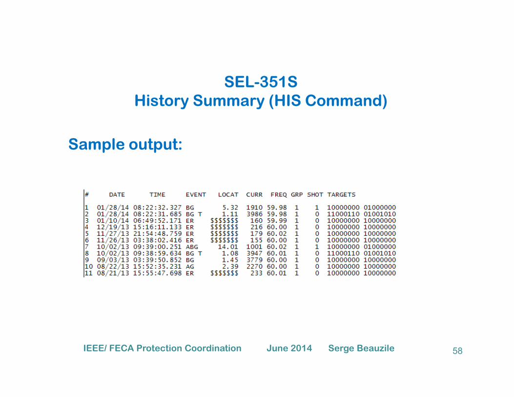
SEL-351SHistory Summary (HIS Command)
Sample output:
58IEEE/ FECA Protection Coordination June 2014 Serge Beauzile

SEL-351SSequence of Events Recording (SER)Sequence of Events Recording (SER)
59IEEE/ FECA Protection Coordination June 2014 Serge Beauzile

SEL-351SMetering Data (MET Command)
Sample output - Metering Data (MET):
60IEEE/ FECA Protection Coordination June 2014 Serge Beauzile

SEL-351SMetering Data (MET Command)
Sample output - Metering Demand (MET D):
61IEEE/ FECA Protection Coordination June 2014 Serge Beauzile

SEL-351SMetering Data (MET Command)
Sample output - Metering Energy (MET E):
62IEEE/ FECA Protection Coordination June 2014 Serge Beauzile

SEL-351SMetering Data (MET Command)
Sample output - Metering Max/Min (MET M):
63IEEE/ FECA Protection Coordination June 2014 Serge Beauzile

Differential RelaysProtection of a Delta‐Wye Transformer
II II IA
B
a
b
Ia
5252Ib
Ia‐Ib IaIa
Ia‐Ib
Ib‐Ic
Ia‐Ib
Ib‐Ic IaB
C
b
c
5252Ic
Ib‐Ic
Ic‐Ia
Ib
Ic
Ib
Ic
Ic‐IaIc‐IaIb
Ic
Ia‐Ib
Ia‐Ib R ROP
OP
Ia‐Ib
I I
Ic‐Ia
Ib‐Ic
R
R
R
ROP
OP Ic‐Ia
Ib‐Ic Ib‐Ic
Ic‐Ia
Power System Protection -64- Ralph Fehr, Ph.D., P.E. – October 28, 2013
R R

Distance RelaysyProtection Features
– Four zones of distance protection– Pilot schemes
– Phase/Neutral/Ground TOCs
Phase/Neutral/Ground IOCs
Power System Protection -65- Ralph Fehr, Ph.D., P.E. – October 28, 2013
– Phase/Neutral/Ground IOCs

Distance RelaysyProtection Features ‐ continued
– Negative sequence TOC
– Negative sequence IOC
– Phase directional OCs
– Neutral directional OC
– Negative sequence directional OC
– Phase under‐ and overvoltage
– Power swing blocking
– Out of step tripping
Power System Protection -66- Ralph Fehr, Ph.D., P.E. – October 28, 2013

Distance RelaysControl FeaturesControl Features
B k F il ( h / t l )– Breaker Failure (phase/neutral amps)
– Synchrocheck
– Autoreclosing
Power System Protection -67- Ralph Fehr, Ph.D., P.E. – October 28, 2013

Distance RelaysMetering FeaturesMetering Features
F lt L t− Fault Locator− Oscillography− Event Recorder− Data Logger− Phasors / true RMS / active, reactive and apparent power, power factorand apparent power, power factor
Power System Protection -68- Ralph Fehr, Ph.D., P.E. – October 28, 2013

Distance RelaysZones of Protection Zone 2
X
Line Impedance (Line A)Zone 1
Zone 2
123Line Impedance (Line A)
Zone 2
Z 3
12
31
Line AA1 A2
Zone 1
Zone 3 341
2
Bus 1 Bus 2
Normal Load
Distance Relayat Bus 1
R
Zone 1 – fastest (80% of line)
2 Normal Load
to protect Line A
Zone 3
Zone 2 – slower (120% of line)Zone 3 –(backwards Use in Pilot
Protection for current
4
Reversal logic)
Power System Protection -69- Ralph Fehr, Ph.D., P.E. – October 28, 2013

Zone 3Zone 2 Zone 2
Zone of Protection∆t
Zone 1 Zone 1
Zone 2
∆t∆t
∆t
1 2 43
Zone 1Zone 1 Zone 1
Zone 3
Zone 2Zone 2
Zone 3Zone 1: Under reaches the remote line end Typically 0.7 Z1L to 0.9 Z1L
With no intentional time delay.
Z 2 O h th t li d T i ll 1 2 ZZone 2: Over reaches the remote line end Typically 1.2 Z1L
with definite time delay.
Zone 3: Over reaches the longest adjacent linei h d fi i i d l h Z 2with definite time delay greater than Zone2.
70IEEE/ FECA Protection Coordination June 2014 Serge Beauzile

Unconventional Zone 2 & Zone 3 Settings
Zone 2
Zone 1
Zone 2∆t
Long Line Short Line
Be Mindful when Applying General Rules
71IEEE/ FECA Protection Coordination June 2014 Serge Beauzile

Step Distance Relay Coordination Exercise
Setting the relay at breaker 3 protecting Circuit 2.
Set the Zones of Protection.
The maximum expected load is about 600A.
CTR = 1200:5 or 240:1 PTR = 600:1CTR 1200:5 or 240:1 PTR 600:1
72IEEE/ FECA Protection Coordination June 2014 Serge Beauzile

Distance Relay Coordination Exercise
Circuit 2 & Circuit 5 Impedances Circuit 3 & Circuit 6 Impedances
Z1 = 35.11 83.97˚ Ω primary
Z0 = 111.58 81.46˚ Ω primary
Z1 = 17.56 83.72˚ Ω primary
Z0 = 53.89 81.56˚ Ω primary
Circuit 1& Circuit 4 Impedances
Z1 = 35.21 83.72˚ Ω primary
Z0 = 187.80 81.56˚ Ω primary
73IEEE/ FECA Protection Coordination June 2014 Serge Beauzile

Distance Relay Coordination Exercise
Zone 1 Reach = 0.8 * (35.11 83.97˚) Ω primary Zone 1 Reach = 28.09 83.97˚) Ω primary
Z 2 R h 1 2 * (35 11 83 97˚) Ω i Z 2 R h 42 13 83 97˚) Ω iZone 2 Reach = 1.2 * (35.11 83.97˚) Ω primary
Check Zone 2 reach does not overreach = Circuit 2 Impedance + (Zone 1 of Circuit 3) or (Zone 1of Circuit 6).
General rule = protected Circuit Impedance + Zone 1 of the Shortest Circuit past the protected circuit.
Zone 2 Reach = 42.13 83.97˚) Ω primary
p p p p
Check for Zone 2 Overreach = 35.11. + (0.8 * 17.56) = 49.16 Ω primary
Zone 2 Reach = 42.13 < 49.16 no overreach
Zone 4 Reach = 52.55 83.35˚) Ω primaryZone 4 Reach = (35.11 83.97˚) + (17.56 83.72˚) ( Ω primary)
74IEEE/ FECA Protection Coordination June 2014 Serge Beauzile

Primary / Secondary ImpedanceRelay Input
75

Relay Input
Zone 1 Reach = 28.09 Ω x 240 = 11.24 Ω secondary600
Zone 2 Reach = 42.43 Ω x 240 = 16.97 Ω secondary600
Zone 4 Reach = 28.09 Ω x 240 = 21.02 Ω secondary600
76IEEE/ FECA Protection Coordination June 2014 Serge Beauzile

Overcurrent Supervision Setting Criteria
1) Find the lowest Ø – Ø fault seen by relay 3for a remote end bus (4 10 5 11)
Set above (maximum load) and 60% of min fault.
Zone 1 Phase Fault detector:
for a remote end bus (4, 10, 5, 11).
Zone 2 Phase Fault detector:
Set above (maximum load) and 60% of min fault. 1) Find the lowest Ø – Ø fault seen by relay 3for a remote end bus (6, 12).( , )
Zone 4 Fault detector same as Zone 2
Repeat same process for Ground Fault detector.
77IEEE/ FECA Protection Coordination June 2014 Serge Beauzile

Current InfeedIL =0.5 AZL =2 Ω
IR =1 AZR =1 Ω
IT =0.5 AZT =1 Ω Actual Impedance from L to the Fault is 3Ω
Apparent Impedance = EL
I L
Apparent Impedance = ( IL x ZL) + (IR x ZR)IL
Apparent Impedance = 4Ω
78IEEE/ FECA Protection Coordination June 2014 Serge Beauzile

Thank YouThank You
79IEEE/ FECA Protection Coordination June 2014 Serge Beauzile